US5345722A - Adjustable plastic door frame - Google Patents
Adjustable plastic door frameDownload PDFInfo
- Publication number
- US5345722A US5345722AUS08/019,567US1956793AUS5345722AUS 5345722 AUS5345722 AUS 5345722AUS 1956793 AUS1956793 AUS 1956793AUS 5345722 AUS5345722 AUS 5345722A
- Authority
- US
- United States
- Prior art keywords
- section
- trim
- door frame
- frame according
- adjustable
- Prior art date
- Legal status (The legal status is an assumption and is not a legal conclusion. Google has not performed a legal analysis and makes no representation as to the accuracy of the status listed.)
- Expired - Fee Related
Links
- 239000004033plasticSubstances0.000titleclaimsdescription10
- 229920003023plasticPolymers0.000titleclaimsdescription10
- 238000001816coolingMethods0.000claimsdescription16
- 238000001125extrusionMethods0.000claimsdescription14
- 230000000712assemblyEffects0.000claimsdescription10
- 238000000429assemblyMethods0.000claimsdescription10
- 125000000391vinyl groupChemical group[H]C([*])=C([H])[H]0.000claimsdescription7
- 229920002554vinyl polymerPolymers0.000claimsdescription7
- 239000003000extruded plasticSubstances0.000claimsdescription6
- 229910052751metalInorganic materials0.000claimsdescription2
- 239000002184metalSubstances0.000claimsdescription2
- 238000002360preparation methodMethods0.000claimsdescription2
- 239000007787solidSubstances0.000claims2
- 230000003014reinforcing effectEffects0.000claims1
- 238000004519manufacturing processMethods0.000description8
- 230000006835compressionEffects0.000description4
- 238000007906compressionMethods0.000description4
- 238000009434installationMethods0.000description3
- 239000000463materialSubstances0.000description3
- 238000000465mouldingMethods0.000description3
- 238000000034methodMethods0.000description2
- 230000004048modificationEffects0.000description2
- 238000012986modificationMethods0.000description2
- 125000006850spacer groupChemical group0.000description2
- 239000002023woodSubstances0.000description2
- 239000004606Fillers/ExtendersSubstances0.000description1
- 229910052782aluminiumInorganic materials0.000description1
- XAGFODPZIPBFFR-UHFFFAOYSA-NaluminiumChemical compound[Al]XAGFODPZIPBFFR-UHFFFAOYSA-N0.000description1
- 230000015572biosynthetic processEffects0.000description1
- 238000010276constructionMethods0.000description1
- 239000000112cooling gasSubstances0.000description1
- 239000000110cooling liquidSubstances0.000description1
- 230000003247decreasing effectEffects0.000description1
- 230000013011matingEffects0.000description1
- 230000002787reinforcementEffects0.000description1
- 230000000717retained effectEffects0.000description1
- 239000010421standard materialSubstances0.000description1
Images


Classifications
- E—FIXED CONSTRUCTIONS
- E06—DOORS, WINDOWS, SHUTTERS, OR ROLLER BLINDS IN GENERAL; LADDERS
- E06B—FIXED OR MOVABLE CLOSURES FOR OPENINGS IN BUILDINGS, VEHICLES, FENCES OR LIKE ENCLOSURES IN GENERAL, e.g. DOORS, WINDOWS, BLINDS, GATES
- E06B1/00—Border constructions of openings in walls, floors, or ceilings; Frames to be rigidly mounted in such openings
- E06B1/04—Frames for doors, windows, or the like to be fixed in openings
- E06B1/12—Metal frames
- E06B1/18—Metal frames composed of several parts with respect to the cross-section of the frame itself
- E06B1/20—Metal frames composed of several parts with respect to the cross-section of the frame itself adjustable with respect to the thickness of walls
- E—FIXED CONSTRUCTIONS
- E06—DOORS, WINDOWS, SHUTTERS, OR ROLLER BLINDS IN GENERAL; LADDERS
- E06B—FIXED OR MOVABLE CLOSURES FOR OPENINGS IN BUILDINGS, VEHICLES, FENCES OR LIKE ENCLOSURES IN GENERAL, e.g. DOORS, WINDOWS, BLINDS, GATES
- E06B1/00—Border constructions of openings in walls, floors, or ceilings; Frames to be rigidly mounted in such openings
- E06B1/70—Sills; Thresholds
Definitions
- the present inventionrelates to an adjustable door frame formed of plastic.
- First and second membersform each side jamb assembly and header assembly, with the connection between the respective first and second members of each assembly being adjustable to compensate for varying wall thicknesses.
- This door frameincludes a header assembly for the top of the doorway opening and latch and hinge jamb assemblies for the sides of the doorway opening in the wall.
- the thickness of the wall in which the door is to be locatedoften varies. These variations result from variations in the standard materials used as well as in the assembly of those materials in forming the walls. To accommodate these thickness variations in the wall, the frame must be adjustable.
- the frameshould be adaptable to a wide variety of uses, including the addition of a screen or storm door and the addition or omission of exterior and interior trim.
- latch and hinge jamb assemblies and the header assemblyshould be of generally the same construction.
- plastic framesparticularly those of vinyl, have become viable for residential use, as well as for commercial use.
- plastic door framesis expanding.
- an object of the present inventionis to provide an adjustable door frame which can be easily, economically manufactured of plastic.
- Another object of the present inventionis to provide an adjustable door frame with the same structure for the latch jamb, hinge jamb and header assemblies.
- a further object of the present inventionis to provide an adjustable door frame which is adaptable to receive a screen or storm door, and can be used with or without exterior trim.
- Yet another object of the present inventionis to provide an adjustable door frame which is rugged, sturdy, and easy to install.
- an adjustable door framecomprising first and second members, each of which is unitarily formed.
- the first memberincludes a first trim section for overlying a wall surface adjacent the wall doorway opening, a first inside section extending substantially perpendicularly from the first trim section for extending into the doorway opening, a first door abutment section extending substantially perpendicularly from the first inside section at an end thereof remote from the first trim section in a direction parallel to and opposite to the first trim section, and a pair of parallel flanges extending substantially perpendicularly from the first abutment section at its end remote from the first inside section in a direction parallel to and opposite to the first inside section.
- the flangesdefine a slot therebetween.
- the second memberincludes a second trim section for overlying the opposite side of the wall, a second inside section extending substantially perpendicularly from the second trim section for extending into the doorway opening toward and adjacent to the first inside section, and a tongue section extending from the second inside section at its end remote from the second trim section as a coplanar extension thereof.
- the slotreceives and frictionally engages the tongue section.
- the engagement of the tongue section in the slotprovides an adjustable connection of the first and second members.
- This adjustable connectionwill compensate for varying wall thicknesses, while providing a structure which is sturdy, simple to install and manufacture, inexpensive to manufacture, and is highly adaptable to varied uses.
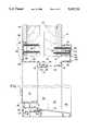
- FIG. 1is a partial, side elevational view in section of adjustable door frame according to a first embodiment of the present invention
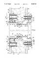
- FIG. 2is a partial, top plan view in section of a door frame according to the first embodiment of the present invention
- FIG. 3is a partial, top plan view in section of a door frame according to a second embodiment of the present invention.
- FIG. 4is a partial, top plan view in section of a door frame according to a third embodiment of the present invention.
- FIGS. 5 and 6are side elevational views of cooling roller systems for forming the door frame assembly members according to the present invention.
- the adjustable door frame of the first embodiment of the present inventionpivotally mounts a door 10 in a doorway 12 in a wall 14.
- the door frameincludes a latch jamb assembly 16, a hinge jamb assembly 18, and a header assembly 20.
- Each of these three assembliesis formed of two mating members.
- the cross-sectional shapes of the two members in each assemblyare essentially identical.
- the wall 14 having the doorway 12can be of any conventional form.
- the wallcan include wood studs 22 on which dry wall panels 24 are mounted.
- the dimensional variations in the studs and dry wall panels, as well as the assembly thereof,produce the variations in the thickness of the entire wall, that is, between the oppositely directed surfaces of the dry wall panels 24.
- latch jamb assembly 16comprises a latch jamb 26 and a closure jamb 28.
- Latch jamb 26 and closure jamb 28form the two members which are adjustable relative to each other to accommodate for the different wall thicknesses and are secured to the wall.
- Each of the latch jamb and closure jambis unitarily formed from a single piece of extruded plastic, particularly vinyl.
- Latch jamb 26comprises a trim section 30 which is planar and overlies a wall surface adjacent doorway 12 in wall 14.
- An inside section 32extends substantially perpendicularly from trim section 30 and into the doorway.
- the inside sectionis also essentially planar.
- the inside sectionterminates at a door abutment section 34.
- Door abutment section 34extends perpendicularly from the inside section at its end remote from trim section 30.
- the door abutment sectionextends in a direction parallel to and opposite to trim section 30, i.e., towards the center of the doorway and towards hinge jamb assembly 18.
- the surface of abutment section 34 facing door 10is uninterrupted and planar.
- a pair of parallel, spaced, generally planar flanges 36 and 38and extend substantially perpendicularly from door abutment section 34 at its end remote from inside section 32.
- the flangesextend in a direction parallel to and opposite to the inside section, i.e., towards closure jamb 28, and define a slot 40 therebetween.
- a door seal or weatherseal 42is mounted on the planar surface of abutment section 34 facing door 10.
- Trim section 30terminates at its end remote from inside section 32 in a planar lip 44.
- Lip 44extends substantially perpendicularly from trim section 30, and is parallel to and extends in the same direction as inside section 32.
- a second planar lip 46extends perpendicularly from trim section 30 between lip 44 and inside section 32, and extends in the same direction as inside section 32. Lips 44 and 46 have coplanar free end surfaces 48 and 50, respectively.
- Latch jamb 26is mounted to wall 14 with spacer wedges 56 located under inside section 32. Screws 58 and 60 extend through countersunk holes in trim section 30 and inside section 32, respectively, and into wall 14 to secure latch jamb 26 in place on the wall.
- a suitable latch mechanism(not illustrated) can be mounted on inside section 32 to mate with a locking and latching mechanism conventionally used on doors.
- the latch jambcan be reinforced in the area of the latch mechanism by a metal reinforcement plate 61 secured by screws to inside section 32 opposite strike plate 62.
- Closure jamb 28has a planar trim section 64 overlying a wall surface adjacent a side of doorway 12 opposite from trim section 30.
- An inside section 66extends substantially perpendicularly from trim section 64 for extending into the doorway toward and adjacent to inside section 32 of latch jamb 26.
- Inside section 66is joined to trim section 64 by two parts 68 and 70, which together define a door abutment section.
- Part 68extends directly from trim section 64 and is substantially perpendicular thereto.
- Part 70extends perpendicularly from part 68 at an end thereof remote from trim section 64, and is joined directly to and is perpendicular to inside section 66.
- the door abutment section defined by parts 68 and 70provides a recess for accommodating a screen or storm door 72.
- Tongue section 74is a coplanar extension of inside section 66, is received with slot 40 and frictionally engages flanges 36 and 38.
- a planar end lip 78extends perpendicularly from trim section 64 from its end remote from part 68.
- the lipextends in the same direction as part 68 and inside section 66, and extends toward wall 14.
- Planar inside lips 80extend perpendicularly trim section 64 between lip 78 and part 68 and parallel to and spaced from each other, and extend in the same direction as lip 78. Lips 78 and 80 have coplanar free end surfaces.
- screws 84extend through countersunk holes in trim section 64 and into the wall 14, as illustrated.
- Hinge jamb assembly 18comprises a hinge jamb 86 and a closure jamb 88, each of which like latch jamb 26 and closure jamb 28 are unitarily formed from single pieces of extruded plastic, particularly vinyl.
- Hinge jamb 86is constructed with a cross-sectional configuration which is substantially identical to latch jamb 26, except for the preparation for supporting the hinges.
- hinge jamb 86has lips 44 and 46, a trim section 30, an inside section 32, a door abutment section 34 and flanges 36 and 38 defining a slot 40.
- the hinge jambis mounted on wall 14, and is secured by screws 58 and 60 and spacer wedges 56.
- hinge jamb 86At appropriate locations along the length of hinge jamb 86, inside section 32 has holes for screws to attach each hinge 92.
- Hinge 92comprises a wall plate 94 coupled to the hinge Jamb and a door plate 98 is secured to the hinged edge of door 10 by screws.
- a compression weatherseal 42is mounted on and attached to door abutment section 34 of hinge jamb 86.
- Closure jamb 88is identical to closure jamb 28, and includes lips 78 and 80, a trim section 64, parts 68 and 70, inside section 66, tongue section 74 and tapered tip 76. Slot 40 of hinge jamb 86 receives and frictionally engages tongue section 74. Closure jamb 88 is secured to the wall by screws 84.
- Header assembly 20comprises a base header 108 and a closure header 110.
- the base header and the closure headerare unitarily formed from single pieces of extruded plastic, particularly vinyl, in the same manner as the previously described latch jamb 26 and closure jamb 28, respectively.
- base header 108The cross-sectional configuration of base header 108 is essentially identical to that of latch jamb 26. Specifically, base header 108 includes lips 44 and 46, a trim section 30, an inside section 32, a door abutment section 34 and flanges 36 and 38 defining a slot 40. A weatherseal 42 is supported on the door abutment section. Base header 108 is secured to wall 14 by screws 58.
- Closure header 110is essentially identical in cross-sectional configuration to closure jambs 28 and 88. Specifically, closure header 110 includes lips 78 and 80, a trim section 64, secondary door abutment parts 68 and 70, inside section 66 and a tongue section 78 with a tapered tip 76. The tongue section is received in slot 40 of base header 108. The closure header is secured to the wall by screws 84.
- Each of latch jamb 26, hinge jamb 86, closure jambs 28 and 88, base header 108 and closure header 110are separately formed in a suitable manufacturing facility.
- the base headercan be attached in a conventional manner to the latch and hinge jambs at the installation site or the manufacturing facility.
- the closure headercan be attached in a conventional manner to the closure jambs at the installation site or the manufacturing facility.
- a typical threshold assemblyis illustrated in FIG. 1, and comprises an aluminum extender threshold 112 and a vinyl base threshold 114.
- the base threshold 114engages and mates with a sweep 116 suitably mounted on the door to provide a seal at the lower edge of the door.
- Such threshold assemblyis typically used on an outside entrance door.
- An inside surface of a doorwaycan be decorated with moldings 118 mounted over trim sections 30.
- a second embodiment of the present inventioncomprises a modified latch jamb 120.
- the closure jambs 28 and 88are identical to those of the first embodiment, and thus are not described in detail.
- Features of the second embodiment that are similar to those of the first embodimentare identified with like reference numbers.
- Latch jamb 120differs from latch jamb 128 in the configuration of the abutment section.
- Abutment section 122 of latch jamb 120has a groove 124 adjacent the juncture of inside section 32 and abutment section 122. Groove 124 retains a door seal or weather seal 126.
- Weather seal 126includes a stem 128 located and retained in groove 124, a compressible part 130 attached to this stem and extending outside of the groove, and a magnetic part 132 attached to the compressible part.
- the magnetic partoverlies abutment section 122 for engaging the adjacent door edge and providing a seal therebetween.
- Groove 124is defined by portions 134 and 136, as well as a section of flange 38.
- Portion 134is generally parallel and is spaced from flange 138 and inside section 32.
- Portion 136joins portion 134 to flange 38 intermediate the opposite ends of flange 38.
- Hinge Jamb 138 of FIG. 3is modified to provide a groove 124 in abutment section 122.
- the grooveis defined by portions 134 and 136, as well as flange 38.
- a compression seal 140is mounted on abutment section 122 of latch jamb 138.
- the compression weatherseal 140includes a stem 142 secured in hinge jamb groove 124 and a compression part 144 overlying and engaging hinge jamb abutment section 122 and the adjacent surface of door 10.
- FIG. 4illustrates a modification of the embodiment of FIG. 3.
- latch jamb 150 and hinge jamb 152are modified from the latch and hinge jambs of FIG. 3 in the form of the trim sections.
- the remaining features of the door assembly illustrated in FIG. 4are similar to features of the previous embodiments, and are identified with like reference numbers.
- trim sections 154 of latch jamb 150 and hinge jamb 152do not have planar outer surfaces that can be arranged coplanar with the outer surfaces of dry wall panels 124, as illustrated in FIGS. 1-3. Rather, trim sections 154 are profiled to take the shape of a decorative molding, thereby eliminating the need for molding 118 as in FIGS. 1-3. Additionally, two lips 156 are provided intermediate end lip 44 and inside section 32. Closure jambs 28 and 88 are again identical to the first embodiment, and thus, are not described in detail.
- the headeris for use with the second and third embodiments is modified as shown for the hinge and latch jambs of FIGS. 3 and 4.
- the profiles for the plastic extrusions used to form latch jambs, hinge jambs, base headers, closure jambs and closure headers for frame assemblies according to the present inventionfacilitate formation by plastic extrusion and then contact of the extrusions by a set of cooling rolls, immediately downstream of the plastic extrusion head. Representative cooling rolls are illustrated in FIGS. 4 and 5.
- the cooling rolls 160, 161, 162 and 163are each rotatably mounted by the respective shaft 164.
- the adjacent faces of the rollsare suitably profiled to conform to the extruded plastic frame member 165 or 166.
- the cooling rollerssimultaneously establish and retain the extruded shape, while cooling the extrusion during passage between the rolls. Cooling liquid or gas can be passed through the cooling rolls to enhance the cooling operation.
- cooling rollsenables the extrusion process to operate at a significantly higher speed.
- the use of the cooling rolls to enhance manufactureis facilitated by the present invention by the use of such features as inwardly extending flanges and the lack of any under cut portions in the frame members.
Landscapes
- Engineering & Computer Science (AREA)
- Civil Engineering (AREA)
- Structural Engineering (AREA)
- Wing Frames And Configurations (AREA)
Abstract
Description
Claims (27)
Priority Applications (1)
| Application Number | Priority Date | Filing Date | Title |
|---|---|---|---|
| US08/019,567US5345722A (en) | 1992-03-27 | 1993-02-18 | Adjustable plastic door frame |
Applications Claiming Priority (2)
| Application Number | Priority Date | Filing Date | Title |
|---|---|---|---|
| US07/858,515US5187898A (en) | 1992-03-27 | 1992-03-27 | Adjustable door frame |
| US08/019,567US5345722A (en) | 1992-03-27 | 1993-02-18 | Adjustable plastic door frame |
Related Parent Applications (1)
| Application Number | Title | Priority Date | Filing Date |
|---|---|---|---|
| US07/858,515Continuation-In-PartUS5187898A (en) | 1992-03-27 | 1992-03-27 | Adjustable door frame |
Publications (1)
| Publication Number | Publication Date |
|---|---|
| US5345722Atrue US5345722A (en) | 1994-09-13 |
Family
ID=46247145
Family Applications (1)
| Application Number | Title | Priority Date | Filing Date |
|---|---|---|---|
| US08/019,567Expired - Fee RelatedUS5345722A (en) | 1992-03-27 | 1993-02-18 | Adjustable plastic door frame |
Country Status (1)
| Country | Link |
|---|---|
| US (1) | US5345722A (en) |
Cited By (42)
| Publication number | Priority date | Publication date | Assignee | Title |
|---|---|---|---|---|
| US5528869A (en)* | 1989-11-18 | 1996-06-25 | Boomer; Kenneth R. | Building product |
| USD374488S (en) | 1995-04-07 | 1996-10-08 | Yuan-Chi Wang | Adjustable frame |
| US5603191A (en)* | 1995-07-18 | 1997-02-18 | Wu; Ming-Hsin | Plastic door frame and method of mounting the same |
| US5619828A (en)* | 1994-12-19 | 1997-04-15 | Pella Corporation | Installation fin for windows and doors |
| USD381087S (en)* | 1995-11-13 | 1997-07-15 | Dominon Plastics Inc. | Door jamb |
| US5682715A (en)* | 1995-10-30 | 1997-11-04 | General Products Company, Inc. | Two piece center mull for multiple door assembly |
| US5791104A (en)* | 1995-12-01 | 1998-08-11 | Pella Corporation | Jamb extension assembly for doors and windows |
| US5845439A (en)* | 1996-10-30 | 1998-12-08 | Hendley; Darrell N. | Adjustable door and frame assembly |
| US5934030A (en)* | 1997-08-29 | 1999-08-10 | Composite Structures, Inc. | Door frame |
| US5974745A (en)* | 1996-04-25 | 1999-11-02 | Barr; Gerald L. | Self-aligning prefabricated door frame assembly |
| US6131340A (en)* | 1998-02-03 | 2000-10-17 | Tecla Company, Inc. | Sliding door for boat cabin companionway |
| US6138413A (en)* | 1996-12-12 | 2000-10-31 | Huron Window Corporation | Standardized framing section for closure wings |
| US6141922A (en)* | 1997-07-02 | 2000-11-07 | Tempco Products Company | Trim assembly and method of manufacture |
| US6298555B1 (en)* | 1995-09-20 | 2001-10-09 | Al International Srl | Method of making a duct utilizing a grip flange |
| US6393779B1 (en) | 2000-07-19 | 2002-05-28 | Ex Cell Cellular Pvc Building Components, Inc. | Door frame assembly and method of mounting the same |
| US6412227B1 (en)* | 1997-09-08 | 2002-07-02 | Royal Group Technologies Limited | Composite door frames |
| GB2384021A (en)* | 2002-01-14 | 2003-07-16 | Komfort Office Environments | Door frame profile |
| GB2385085A (en)* | 2002-02-11 | 2003-08-13 | Ian Douglas Law | Telescopic locating component for doorframe |
| RU2230868C2 (en)* | 2000-11-07 | 2004-06-20 | Мишель ИВ | Finishing section, method for finishing section manufacture, and method for finishing window and door apertures |
| US6922959B1 (en) | 2003-01-24 | 2005-08-02 | William Hileman | Apparatus and method for correcting a misaligned door and door frame |
| US20060107608A1 (en)* | 2004-11-22 | 2006-05-25 | Michael Mirau | Adaptable door frame apparatus |
| US20060107577A1 (en)* | 2004-10-15 | 2006-05-25 | Paul Root | Housing with a front frame covering the housing opening |
| RU2281367C1 (en)* | 2005-04-11 | 2006-08-10 | Сергей Евгеньевич Варламов | Method for door and window opening finishing and component set for above method realization |
| US20080036238A1 (en)* | 2006-08-11 | 2008-02-14 | Weeda Dewey J | Secondary door and temperature control system and method |
| US20080116707A1 (en)* | 2006-11-22 | 2008-05-22 | Mantaline Corporation | Sealing Assembly |
| RU2343263C2 (en)* | 2007-02-26 | 2009-01-10 | Дмитрий Георгиевич Федотов | System of decorative profiles of windows and doorways openings |
| US20090049780A1 (en)* | 2007-04-24 | 2009-02-26 | Pn Ii, Inc. | Edge cladding |
| US20100043321A1 (en)* | 2008-02-14 | 2010-02-25 | All-Terior Systems, Llc | Systems and methods for finishing a penetration in a concrete structure during construction |
| RU2397304C1 (en)* | 2008-12-16 | 2010-08-20 | Станислав Владимирович Тихонов | Universal system of finishing profiles for jambs of window and door openings |
| RU2430218C2 (en)* | 2008-12-30 | 2011-09-27 | Закрытое акционерное общество "Научно-исследовательский, проектно-конструкторский и технологический институт ВНИИжелезобетон" | Method to install fastening element of suspended equipment in outer wall of building |
| US8122653B2 (en)* | 2006-02-28 | 2012-02-28 | All-Terior Systems, Llc | Systems and methods for finishing an edge of an insulated concrete form (ICF) wall |
| US20140096472A1 (en)* | 2012-10-05 | 2014-04-10 | Fiber Cement Foam Systems Insulation, LLC | Method and A Device to Attach Building Trims |
| US8806819B1 (en)* | 2013-03-14 | 2014-08-19 | Logan R Teilborg | Removable wall opening frames |
| US8966823B1 (en)* | 2013-08-26 | 2015-03-03 | Endura Products, Inc. | Press-in sill extender for thresholds |
| US9290987B2 (en) | 2012-04-09 | 2016-03-22 | Jason Gray Yeomans | Window frame with jamb extender |
| IT201700119699A1 (en)* | 2017-10-23 | 2019-04-23 | Luca Geron | SYSTEM FOR LOCKING WATER INFILTRATIONS IN A WINDOW |
| US20210388664A1 (en)* | 2020-06-11 | 2021-12-16 | Climatecraft, Inc. | Adjustable door frame for hvac air handler |
| US20220228421A1 (en)* | 2021-01-20 | 2022-07-21 | Vinyl Window Designs | Adjustable jamb extension |
| US20220389749A1 (en)* | 2021-06-07 | 2022-12-08 | Aadg, Inc. | Adjustable frame with a thermal break seal |
| US11746587B1 (en)* | 2022-08-25 | 2023-09-05 | Chad Joseph Hildreth | Doorframe fastening device and method of use |
| GB2626171A (en)* | 2023-01-12 | 2024-07-17 | Kingsway Enterprises Uk Ltd | Door system |
| ES2993957A1 (en)* | 2023-07-07 | 2025-01-14 | Adinor S L U | Adjustable edge banding woodworking set |
Citations (33)
| Publication number | Priority date | Publication date | Assignee | Title |
|---|---|---|---|---|
| US1048988A (en)* | 1912-02-02 | 1912-12-31 | Robert D Mayo Sr | Metal casing. |
| US1715579A (en)* | 1929-06-04 | Metallic door ob | ||
| US2742117A (en)* | 1951-07-30 | 1956-04-17 | Andean Corp | Adjustable door jamb |
| US2860744A (en)* | 1955-03-07 | 1958-11-18 | Conjaur Corp | Adjustable door frames |
| US2893070A (en)* | 1957-11-15 | 1959-07-07 | Raymond V Gauthier | Adjustable weather-stripped door jamb |
| US3032837A (en)* | 1959-12-14 | 1962-05-08 | Ready Hung Door Mfg Company Of | Combination door-hung frame with split sill |
| US3324599A (en)* | 1965-05-06 | 1967-06-13 | John J Brost | Telescoping aluminum frame |
| US3364624A (en)* | 1966-12-12 | 1968-01-23 | Davis Simmie | All-purpose door frame |
| US3420003A (en)* | 1967-05-05 | 1969-01-07 | Robert S Cline | Adjustable door frame |
| US3520085A (en)* | 1968-12-04 | 1970-07-14 | American Air Filter Co | Adjustable door frame |
| US3545135A (en)* | 1969-04-10 | 1970-12-08 | Philip Ben Lieber | Door jamb |
| US3654734A (en)* | 1969-06-03 | 1972-04-11 | Stratford Ind Inc | Adjustable door or window frame |
| US3788019A (en)* | 1971-11-22 | 1974-01-29 | Binkley Co | Adjustable metal door frame construction |
| US3800488A (en)* | 1972-02-16 | 1974-04-02 | C Swanson | Door jamb with mitered joints and l-shaped brackets |
| US3826050A (en)* | 1973-03-14 | 1974-07-30 | Fruehauf Corp | Jamb construction |
| US3881279A (en)* | 1973-05-08 | 1975-05-06 | Charles S Kirton | Doorframes |
| US3906671A (en)* | 1974-03-20 | 1975-09-23 | Tex Steel Corp | Adjustable door frame |
| DE2422180A1 (en)* | 1974-05-08 | 1975-11-20 | Herbert Hess | Surrounding frame for window - has movable flange permanently pressed against window and held by parts in profile |
| US4395855A (en)* | 1980-04-03 | 1983-08-02 | Windor Sales Limited | Knock down expandable reversible door frame |
| US4467576A (en)* | 1982-11-10 | 1984-08-28 | Buergers Helmut | Outer frame for facing a wall opening |
| US4531337A (en)* | 1983-02-18 | 1985-07-30 | Holdiman Joseph W | Door casement |
| US4589229A (en)* | 1981-01-07 | 1986-05-20 | Warren Lawrence L | Adjustable door jamb assembly |
| US4782630A (en)* | 1986-08-25 | 1988-11-08 | Kleyn Robert J | Closure frame assemblies |
| US4787184A (en)* | 1986-04-04 | 1988-11-29 | Boidron Guy A D | Door and window frame |
| US4791758A (en)* | 1987-07-28 | 1988-12-20 | Windor Manufacturing Ltd. | Expandable prehangable split door frame |
| US4793109A (en)* | 1983-08-16 | 1988-12-27 | Eizen Noach | Method and apparatus for facing wooden door frames |
| US4813204A (en)* | 1988-01-11 | 1989-03-21 | Dunbarton Corporation | Adjustable door jamb assembly |
| US4878325A (en)* | 1987-02-25 | 1989-11-07 | Tuyl James E Van | Two piece adjustable, reusable metal door frame |
| US4912879A (en)* | 1987-10-05 | 1990-04-03 | Copco Door Company | Adjustable door frame assembly |
| US4986044A (en)* | 1989-07-17 | 1991-01-22 | Fenestra Corporation | Adjustable door frame |
| US4986034A (en)* | 1987-10-05 | 1991-01-22 | Copco Door Company | Adjustable door frame assembly |
| US5070651A (en)* | 1991-01-04 | 1991-12-10 | Jeter Gregory L | Door frame assembly |
| US5187898A (en)* | 1992-03-27 | 1993-02-23 | General Products Company, Inc. | Adjustable door frame |
- 1993
- 1993-02-18USUS08/019,567patent/US5345722A/ennot_activeExpired - Fee Related
Patent Citations (33)
| Publication number | Priority date | Publication date | Assignee | Title |
|---|---|---|---|---|
| US1715579A (en)* | 1929-06-04 | Metallic door ob | ||
| US1048988A (en)* | 1912-02-02 | 1912-12-31 | Robert D Mayo Sr | Metal casing. |
| US2742117A (en)* | 1951-07-30 | 1956-04-17 | Andean Corp | Adjustable door jamb |
| US2860744A (en)* | 1955-03-07 | 1958-11-18 | Conjaur Corp | Adjustable door frames |
| US2893070A (en)* | 1957-11-15 | 1959-07-07 | Raymond V Gauthier | Adjustable weather-stripped door jamb |
| US3032837A (en)* | 1959-12-14 | 1962-05-08 | Ready Hung Door Mfg Company Of | Combination door-hung frame with split sill |
| US3324599A (en)* | 1965-05-06 | 1967-06-13 | John J Brost | Telescoping aluminum frame |
| US3364624A (en)* | 1966-12-12 | 1968-01-23 | Davis Simmie | All-purpose door frame |
| US3420003A (en)* | 1967-05-05 | 1969-01-07 | Robert S Cline | Adjustable door frame |
| US3520085A (en)* | 1968-12-04 | 1970-07-14 | American Air Filter Co | Adjustable door frame |
| US3545135A (en)* | 1969-04-10 | 1970-12-08 | Philip Ben Lieber | Door jamb |
| US3654734A (en)* | 1969-06-03 | 1972-04-11 | Stratford Ind Inc | Adjustable door or window frame |
| US3788019A (en)* | 1971-11-22 | 1974-01-29 | Binkley Co | Adjustable metal door frame construction |
| US3800488A (en)* | 1972-02-16 | 1974-04-02 | C Swanson | Door jamb with mitered joints and l-shaped brackets |
| US3826050A (en)* | 1973-03-14 | 1974-07-30 | Fruehauf Corp | Jamb construction |
| US3881279A (en)* | 1973-05-08 | 1975-05-06 | Charles S Kirton | Doorframes |
| US3906671A (en)* | 1974-03-20 | 1975-09-23 | Tex Steel Corp | Adjustable door frame |
| DE2422180A1 (en)* | 1974-05-08 | 1975-11-20 | Herbert Hess | Surrounding frame for window - has movable flange permanently pressed against window and held by parts in profile |
| US4395855A (en)* | 1980-04-03 | 1983-08-02 | Windor Sales Limited | Knock down expandable reversible door frame |
| US4589229A (en)* | 1981-01-07 | 1986-05-20 | Warren Lawrence L | Adjustable door jamb assembly |
| US4467576A (en)* | 1982-11-10 | 1984-08-28 | Buergers Helmut | Outer frame for facing a wall opening |
| US4531337A (en)* | 1983-02-18 | 1985-07-30 | Holdiman Joseph W | Door casement |
| US4793109A (en)* | 1983-08-16 | 1988-12-27 | Eizen Noach | Method and apparatus for facing wooden door frames |
| US4787184A (en)* | 1986-04-04 | 1988-11-29 | Boidron Guy A D | Door and window frame |
| US4782630A (en)* | 1986-08-25 | 1988-11-08 | Kleyn Robert J | Closure frame assemblies |
| US4878325A (en)* | 1987-02-25 | 1989-11-07 | Tuyl James E Van | Two piece adjustable, reusable metal door frame |
| US4791758A (en)* | 1987-07-28 | 1988-12-20 | Windor Manufacturing Ltd. | Expandable prehangable split door frame |
| US4912879A (en)* | 1987-10-05 | 1990-04-03 | Copco Door Company | Adjustable door frame assembly |
| US4986034A (en)* | 1987-10-05 | 1991-01-22 | Copco Door Company | Adjustable door frame assembly |
| US4813204A (en)* | 1988-01-11 | 1989-03-21 | Dunbarton Corporation | Adjustable door jamb assembly |
| US4986044A (en)* | 1989-07-17 | 1991-01-22 | Fenestra Corporation | Adjustable door frame |
| US5070651A (en)* | 1991-01-04 | 1991-12-10 | Jeter Gregory L | Door frame assembly |
| US5187898A (en)* | 1992-03-27 | 1993-02-23 | General Products Company, Inc. | Adjustable door frame |
Cited By (57)
| Publication number | Priority date | Publication date | Assignee | Title |
|---|---|---|---|---|
| US5528869A (en)* | 1989-11-18 | 1996-06-25 | Boomer; Kenneth R. | Building product |
| US5619828A (en)* | 1994-12-19 | 1997-04-15 | Pella Corporation | Installation fin for windows and doors |
| USD374488S (en) | 1995-04-07 | 1996-10-08 | Yuan-Chi Wang | Adjustable frame |
| US5603191A (en)* | 1995-07-18 | 1997-02-18 | Wu; Ming-Hsin | Plastic door frame and method of mounting the same |
| US6298555B1 (en)* | 1995-09-20 | 2001-10-09 | Al International Srl | Method of making a duct utilizing a grip flange |
| US5682715A (en)* | 1995-10-30 | 1997-11-04 | General Products Company, Inc. | Two piece center mull for multiple door assembly |
| USD381087S (en)* | 1995-11-13 | 1997-07-15 | Dominon Plastics Inc. | Door jamb |
| US5791104A (en)* | 1995-12-01 | 1998-08-11 | Pella Corporation | Jamb extension assembly for doors and windows |
| US5974745A (en)* | 1996-04-25 | 1999-11-02 | Barr; Gerald L. | Self-aligning prefabricated door frame assembly |
| US5845439A (en)* | 1996-10-30 | 1998-12-08 | Hendley; Darrell N. | Adjustable door and frame assembly |
| US6138413A (en)* | 1996-12-12 | 2000-10-31 | Huron Window Corporation | Standardized framing section for closure wings |
| US6141922A (en)* | 1997-07-02 | 2000-11-07 | Tempco Products Company | Trim assembly and method of manufacture |
| US5934030A (en)* | 1997-08-29 | 1999-08-10 | Composite Structures, Inc. | Door frame |
| US6044605A (en)* | 1997-08-29 | 2000-04-04 | Composite Structures, Inc. | Door |
| US6412227B1 (en)* | 1997-09-08 | 2002-07-02 | Royal Group Technologies Limited | Composite door frames |
| US6131340A (en)* | 1998-02-03 | 2000-10-17 | Tecla Company, Inc. | Sliding door for boat cabin companionway |
| US6393779B1 (en) | 2000-07-19 | 2002-05-28 | Ex Cell Cellular Pvc Building Components, Inc. | Door frame assembly and method of mounting the same |
| RU2230868C2 (en)* | 2000-11-07 | 2004-06-20 | Мишель ИВ | Finishing section, method for finishing section manufacture, and method for finishing window and door apertures |
| GB2384021A (en)* | 2002-01-14 | 2003-07-16 | Komfort Office Environments | Door frame profile |
| GB2384021B (en)* | 2002-01-14 | 2005-09-14 | Komfort Office Environments | Partitioning system |
| GB2385085A (en)* | 2002-02-11 | 2003-08-13 | Ian Douglas Law | Telescopic locating component for doorframe |
| GB2385085B (en)* | 2002-02-11 | 2005-08-31 | Ian Douglas Law | Installing architectural finishing components in a building |
| US6922959B1 (en) | 2003-01-24 | 2005-08-02 | William Hileman | Apparatus and method for correcting a misaligned door and door frame |
| US7770351B2 (en)* | 2004-10-15 | 2010-08-10 | Rittal Gmbh & Co. Kg | Housing with a front frame covering the housing opening |
| US20060107577A1 (en)* | 2004-10-15 | 2006-05-25 | Paul Root | Housing with a front frame covering the housing opening |
| US20060107608A1 (en)* | 2004-11-22 | 2006-05-25 | Michael Mirau | Adaptable door frame apparatus |
| RU2281367C1 (en)* | 2005-04-11 | 2006-08-10 | Сергей Евгеньевич Варламов | Method for door and window opening finishing and component set for above method realization |
| US8122653B2 (en)* | 2006-02-28 | 2012-02-28 | All-Terior Systems, Llc | Systems and methods for finishing an edge of an insulated concrete form (ICF) wall |
| US20080036238A1 (en)* | 2006-08-11 | 2008-02-14 | Weeda Dewey J | Secondary door and temperature control system and method |
| US20100270826A1 (en)* | 2006-08-11 | 2010-10-28 | Weeda Dewey J | Secondary door and temperature control system and method |
| US7703835B2 (en) | 2006-08-11 | 2010-04-27 | Weeda Dewey J | Secondary door and temperature control system and method |
| US20080116707A1 (en)* | 2006-11-22 | 2008-05-22 | Mantaline Corporation | Sealing Assembly |
| RU2343263C2 (en)* | 2007-02-26 | 2009-01-10 | Дмитрий Георгиевич Федотов | System of decorative profiles of windows and doorways openings |
| US20090049780A1 (en)* | 2007-04-24 | 2009-02-26 | Pn Ii, Inc. | Edge cladding |
| US8281532B2 (en)* | 2007-04-24 | 2012-10-09 | Pn Ii, Inc. | Edge cladding |
| US9631416B2 (en) | 2007-04-24 | 2017-04-25 | Pn Ii, Inc. | Edge cladding |
| US20100043321A1 (en)* | 2008-02-14 | 2010-02-25 | All-Terior Systems, Llc | Systems and methods for finishing a penetration in a concrete structure during construction |
| US8069622B2 (en) | 2008-02-14 | 2011-12-06 | All-Terior Systems Llc | Systems and methods for finishing a penetration in a concrete structure during construction |
| RU2397304C1 (en)* | 2008-12-16 | 2010-08-20 | Станислав Владимирович Тихонов | Universal system of finishing profiles for jambs of window and door openings |
| RU2430218C2 (en)* | 2008-12-30 | 2011-09-27 | Закрытое акционерное общество "Научно-исследовательский, проектно-конструкторский и технологический институт ВНИИжелезобетон" | Method to install fastening element of suspended equipment in outer wall of building |
| US9290987B2 (en) | 2012-04-09 | 2016-03-22 | Jason Gray Yeomans | Window frame with jamb extender |
| US20140096472A1 (en)* | 2012-10-05 | 2014-04-10 | Fiber Cement Foam Systems Insulation, LLC | Method and A Device to Attach Building Trims |
| US9151061B2 (en)* | 2012-10-05 | 2015-10-06 | Fiber Cement Foam Systems Insulation, LLC | Method and a device to attach building trims |
| US9394703B2 (en) | 2012-10-05 | 2016-07-19 | Fiber Cement Foam Systems Insulation, LLC | Method and a device to attach building trims |
| US8806819B1 (en)* | 2013-03-14 | 2014-08-19 | Logan R Teilborg | Removable wall opening frames |
| US8966823B1 (en)* | 2013-08-26 | 2015-03-03 | Endura Products, Inc. | Press-in sill extender for thresholds |
| IT201700119699A1 (en)* | 2017-10-23 | 2019-04-23 | Luca Geron | SYSTEM FOR LOCKING WATER INFILTRATIONS IN A WINDOW |
| EP3473795A1 (en)* | 2017-10-23 | 2019-04-24 | Luca Geron | Anti-water seepage system for a door frame |
| US20210388664A1 (en)* | 2020-06-11 | 2021-12-16 | Climatecraft, Inc. | Adjustable door frame for hvac air handler |
| US20220228421A1 (en)* | 2021-01-20 | 2022-07-21 | Vinyl Window Designs | Adjustable jamb extension |
| US20220389749A1 (en)* | 2021-06-07 | 2022-12-08 | Aadg, Inc. | Adjustable frame with a thermal break seal |
| US11993977B2 (en)* | 2021-06-07 | 2024-05-28 | Aadg, Inc. | Adjustable frame with a thermal break seal |
| US12392193B2 (en) | 2021-06-07 | 2025-08-19 | Aadg, Inc. | Adjustable frame with a thermal break |
| US11746587B1 (en)* | 2022-08-25 | 2023-09-05 | Chad Joseph Hildreth | Doorframe fastening device and method of use |
| GB2626171A (en)* | 2023-01-12 | 2024-07-17 | Kingsway Enterprises Uk Ltd | Door system |
| ES2993957A1 (en)* | 2023-07-07 | 2025-01-14 | Adinor S L U | Adjustable edge banding woodworking set |
| WO2025012500A1 (en)* | 2023-07-07 | 2025-01-16 | Adinor, S.L.U. | Joinery assembly with an adjustable edge |
Similar Documents
| Publication | Publication Date | Title |
|---|---|---|
| US5345722A (en) | Adjustable plastic door frame | |
| US5187898A (en) | Adjustable door frame | |
| US4920718A (en) | Integral door light and related door construction | |
| US4573287A (en) | Double opening exterior french door and door improvements | |
| US5758458A (en) | Wood and vinyl hybrid residential door frame | |
| US4578903A (en) | Corner locking and associated pivot means for extruded plastic sash windows | |
| US4286716A (en) | Building kit for vertical or horizontal sliding windows | |
| CA2248120C (en) | Modular glazing system | |
| US3731430A (en) | Window unit | |
| US3676966A (en) | Door-frame assembly | |
| US4052819A (en) | Double door astragal | |
| US5038538A (en) | Door frame | |
| US6453631B1 (en) | Reinforced coextruded plastic jamb | |
| US4531337A (en) | Door casement | |
| US5634303A (en) | Door jamb assembly with extruded unitary brickmold and stop | |
| US4246731A (en) | Window frame assembly | |
| US3177924A (en) | Storm door assembly | |
| US4488387A (en) | Sliding door weather-sealing device and assembly | |
| US4370828A (en) | Window frame assembly | |
| US4154034A (en) | Door frame construction | |
| US5979129A (en) | Extruded carpentry framing | |
| US4631866A (en) | Composite non-handed door jamb construction | |
| US20050055908A1 (en) | Two part window and door assembly and coupling for interconnecting components thereof | |
| US3854245A (en) | Building structure | |
| US7472519B2 (en) | Door jamb |
Legal Events
| Date | Code | Title | Description |
|---|---|---|---|
| AS | Assignment | Owner name:GENERAL PRODUCTS COMPANY, INC., VIRGINIA Free format text:ASSIGNMENT OF ASSIGNORS INTEREST.;ASSIGNOR:MCKANN, H. SMITH;REEL/FRAME:006450/0412 Effective date:19930212 | |
| FEPP | Fee payment procedure | Free format text:PAT HOLDER CLAIMS SMALL ENTITY STATUS - SMALL BUSINESS (ORIGINAL EVENT CODE: SM02); ENTITY STATUS OF PATENT OWNER: LARGE ENTITY | |
| FPAY | Fee payment | Year of fee payment:4 | |
| AS | Assignment | Owner name:THERMA-TRU VIRGINIA LIMITED COMPANY, VIRGINIA Free format text:ASSIGNMENT OF ASSIGNORS INTEREST;ASSIGNOR:GENERAL PRODUCTS COMPANY, INC.;REEL/FRAME:010804/0093 Effective date:20000424 | |
| FEPP | Fee payment procedure | Free format text:PAT HOLDER NO LONGER CLAIMS SMALL ENTITY STATUS, ENTITY STATUS SET TO UNDISCOUNTED (ORIGINAL EVENT CODE: STOL); ENTITY STATUS OF PATENT OWNER: LARGE ENTITY | |
| AS | Assignment | Owner name:THERMA-TRU VIRGINIA LIMITED COMPANY, VIRGINIA Free format text:ASSET PURCHASE AGREEMENT;ASSIGNOR:GENERAL PRODUCTS COMPANY, INC.;REEL/FRAME:012145/0750 Effective date:20000404 | |
| FPAY | Fee payment | Year of fee payment:8 | |
| AS | Assignment | Owner name:GENERAL ELECTRIC CAPITAL CORPORATION, NEW YORK Free format text:SECURITY INTEREST;ASSIGNORS:THERMA-TRU CORP.;THERMA-TRU HOLDINGS, INC.;THERMA-TRU VIRGINIA LIMITED COMPANY;AND OTHERS;REEL/FRAME:013868/0055 Effective date:20030220 | |
| REMI | Maintenance fee reminder mailed | ||
| LAPS | Lapse for failure to pay maintenance fees | ||
| STCH | Information on status: patent discontinuation | Free format text:PATENT EXPIRED DUE TO NONPAYMENT OF MAINTENANCE FEES UNDER 37 CFR 1.362 | |
| FP | Lapsed due to failure to pay maintenance fee | Effective date:20060913 |