US5345426A - Delay interpolator for digital phased array ultrasound beamformers - Google Patents
Delay interpolator for digital phased array ultrasound beamformersDownload PDFInfo
- Publication number
- US5345426A US5345426AUS08/060,789US6078993AUS5345426AUS 5345426 AUS5345426 AUS 5345426AUS 6078993 AUS6078993 AUS 6078993AUS 5345426 AUS5345426 AUS 5345426A
- Authority
- US
- United States
- Prior art keywords
- delay
- samples
- digital
- digital samples
- fir
- Prior art date
- Legal status (The legal status is an assumption and is not a legal conclusion. Google has not performed a legal analysis and makes no representation as to the accuracy of the status listed.)
- Expired - Lifetime
Links
- 238000002604ultrasonographyMethods0.000titleclaimsabstractdescription38
- 238000005070samplingMethods0.000claimsabstractdescription58
- 230000001934delayEffects0.000claimsabstractdescription37
- 230000003111delayed effectEffects0.000claimsabstractdescription16
- 230000004044responseEffects0.000claimsdescription10
- 238000000034methodMethods0.000abstractdescription5
- 230000008569processEffects0.000abstractdescription3
- 239000000523sampleSubstances0.000description33
- 238000010586diagramMethods0.000description7
- 230000000694effectsEffects0.000description3
- 238000003384imaging methodMethods0.000description3
- 238000012285ultrasound imagingMethods0.000description3
- 238000006243chemical reactionMethods0.000description2
- 230000006870functionEffects0.000description2
- 238000013139quantizationMethods0.000description2
- 238000001228spectrumMethods0.000description2
- 230000015572biosynthetic processEffects0.000description1
- 238000012986modificationMethods0.000description1
- 230000004048modificationEffects0.000description1
- 238000005457optimizationMethods0.000description1
- 210000000056organAnatomy0.000description1
- 230000001012protectorEffects0.000description1
- 230000009467reductionEffects0.000description1
- 230000003362replicative effectEffects0.000description1
- 230000001360synchronised effectEffects0.000description1
Images


Classifications
- G—PHYSICS
- G01—MEASURING; TESTING
- G01S—RADIO DIRECTION-FINDING; RADIO NAVIGATION; DETERMINING DISTANCE OR VELOCITY BY USE OF RADIO WAVES; LOCATING OR PRESENCE-DETECTING BY USE OF THE REFLECTION OR RERADIATION OF RADIO WAVES; ANALOGOUS ARRANGEMENTS USING OTHER WAVES
- G01S7/00—Details of systems according to groups G01S13/00, G01S15/00, G01S17/00
- G01S7/52—Details of systems according to groups G01S13/00, G01S15/00, G01S17/00 of systems according to group G01S15/00
- G01S7/52017—Details of systems according to groups G01S13/00, G01S15/00, G01S17/00 of systems according to group G01S15/00 particularly adapted to short-range imaging
- G01S7/52023—Details of receivers
- G01S7/52025—Details of receivers for pulse systems
- G—PHYSICS
- G10—MUSICAL INSTRUMENTS; ACOUSTICS
- G10K—SOUND-PRODUCING DEVICES; METHODS OR DEVICES FOR PROTECTING AGAINST, OR FOR DAMPING, NOISE OR OTHER ACOUSTIC WAVES IN GENERAL; ACOUSTICS NOT OTHERWISE PROVIDED FOR
- G10K11/00—Methods or devices for transmitting, conducting or directing sound in general; Methods or devices for protecting against, or for damping, noise or other acoustic waves in general
- G10K11/18—Methods or devices for transmitting, conducting or directing sound
- G10K11/26—Sound-focusing or directing, e.g. scanning
- G10K11/34—Sound-focusing or directing, e.g. scanning using electrical steering of transducer arrays, e.g. beam steering
- G10K11/341—Circuits therefor
- G10K11/346—Circuits therefor using phase variation
Definitions
- This inventionrelates to ultrasound imaging systems which utilize phased array beam steering and focusing and, more particularly, to a delay interpolator for use in each channel of a digital phased array beamformer.
- an ultrasound transducercomprises an array of transducer elements.
- the systemincludes n parallel channels, each having a transmitter and a receiver connected to one of the transducer array elements.
- Each transmitteroutputs an ultrasound pulse into an object being imaged, typically the human body.
- the transmitted ultrasound energyis steered and focused by applying appropriate delays to the pulses transmitted from each array element so that the transmitted energy adds constructively at a desired point.
- the pulseis partially reflected back to the transducer array by various structures and tissues in the body.
- the reflected ultrasound energy from an objecttypically arrives at the array elements at different times.
- the received signalsare amplified, delayed and then summed in a receive beamformer.
- the delay for each elementis selected such that the received beam is focused at a desired point.
- the delaysmay be varied dynamically so as to effect focusing on objects at progressively increasing depths as the ultrasound energy is received.
- the signal from each array elementis digitized by an analog-to-digital converter.
- the minimum conversion rate, or sampling rate, which is dictated by the Nyquist theorem,is twice the frequency of the highest component frequency in the received signal.
- the conversion rateis somewhat greater than the Nyquist requirement in order to permit a practical antialiasing filter.
- a digital ultrasound beamformerit is straightforward to implement the delay function when the desired delay is an integer multiple of the sampling period. Such delay may be achieved by the use of a FIFO memory, a two port memory, a shift register or a similar memory device.
- delayswhich are quantized in units smaller than the sampling period in order to obtain highly accurate steering and focusing. For example, assume a 5 MHz phased array transducer having a 100% fractional bandwidth, that is, a spectrum from 2.5 to 7.5 MHz.
- a sampling rate of 20 MHzsatisfies the Nyquist requirement and provides a comfortable guard band for the antialiasing filter.
- a delay quantization of 50 nanoseconds(the sampling period) is easily achieved.
- a delay quantization of about 12 nanosecondsis desired. It would be very expensive to increase the sampling rate to 80 MHz.
- An alternative to increasing the sampling rateis to utilize a delay element that is capable of delays which are quantized in units smaller than the sampling period, thus providing delay interpolation between the sampling period.
- U.S. Pat. No. 4,170,766, issued Oct. 9, 1979 to Pridham et al.discloses a beamformer wherein signal samples are delayed relative to each other by fractional amounts of the sampling period using charge coupled device registers for storing analog samples.
- U.S. Pat. No. 4,787,392issued Nov. 29, 1988 to Saugeon, discloses a technique for delay interpolation in an ultrasound system using two successively received ultrasound signals applied to an interpolator.
- each channel of a beamformerincludes a delay line and a circuit for delay interpolation.
- the circuit for delay interpolationcomprises multiple digital filters, each having a different delay, connected in parallel. The output of one of the digital filters is selected to provide the desired delay.
- a delay interpolatorfor use in each channel of an ultrasound beamformer.
- Received signals from the transducer elements of an ultrasound transducer arrayare converted to digital samples at a sampling rate f.
- the digital samplesare delayed by selected delays, and the delayed digital samples are summed to form a focused received beam.
- the delay interpolatordelays the digital samples in each channel by selected delays that are quantized in increments less than the sampling period 1/f.
- the delay interpolatorcomprises an FIR digital filter including programmable means responsive to delay control information for delaying the digital samples by different delays that are quantized in increments less than the sampling period, and control means responsive to a subdelay control signal representative of a desired delay for supplying the delay control information to the FIR digital filter.
- the delay interpolationis typically used with a coarse delay unit that provides delays in multiples of the sampling period.
- the total delayis the sum of the delays from the coarse delay unit and the delay interpolation.
- control meansincludes means for supplying a set of filter coefficients corresponding to the desired delay.
- the FIR digital filterpreferably comprises multiplier means for multiplying a group of consecutive digital samples by the set of filter coefficients to provide intermediate samples and summing means for summing the intermediate samples to provide an output digital sample.
- all but one of the filter coefficientsare of the form 1/2 m , where m is an integer, and the multiplier means comprises means for shifting the bits of the data samples by m bit positions in response to the control information from the control means.
- the coefficientsare of this form, conventional digital multipliers are not required to multiply the digital samples by the filter coefficients.
- the FIR digital filterfurther includes gain correction means for correcting the gain of the output sample at each selected delay.
- the FIR digital filterhas selectable delays of 0, 1/4, 1/2 and 3/4 of the sampling period.
- the control information and the gain correction informationare preferably stored in a random access memory that is addressed by the subdelay control signal.
- the delay interpolatoris used in a beamformer that forms two or more time multiplexed beams.
- the delay interpolatorfurther includes first means for storing a group of first consecutive digital samples representative of a first beam, second means for storing a group of second consecutive digital samples representative of a second beam and selector means for sequentially supplying the first digital samples and the second digital samples to the FIR digital filter such that the FIR digital filter performs time multiplexed processing of digital samples of the first beam and the second beam.
- an ultrasound beamformer for processing received signals from an array of ultrasound transducer elementscomprises a plurality of processing channels, one coupled to each transducer element of the array.
- Each processing channelcomprises digitizing means for converting the received signal to digital samples at a predetermined sampling rate f, and delay means for delaying the digital samples by predetermined delays to provide delayed digital samples.
- the delay meanscomprises a delay interpolator including an FIR digital filter having programmable means responsive to delay control information for delaying the digital samples by different delays that are quantized in increments less than the sampling period.
- the ultrasound beamformerfurther includes summing means for summing the delayed digital samples to form output samples that are representative of a received beam, and control means for supplying the delay control information to the delay means in each of the processing channels.
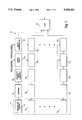
- FIG. 1is a block diagram of a digital phased array ultrasound beamformer in accordance with the present invention
- FIG. 2is a block diagram of a delay interpolator in accordance with the present invention.
- FIG. 3is a block diagram of a preferred embodiment of the delay interpolator in accordance with the present invention.
- FIG. 4is a block diagram of storage and multiplexing circuitry for operation of the delay interpolator in a time multiplexed beamformer.
- a simplified block diagram of an ultrasound transducer array and a digital phased array beamformeris shown in FIG. 1.
- a phased array ultrasound transducer 10includes transducer elements 10 1 , 10 2 , . . . 10 n .
- the transducer elementsare typically arranged in a linear or curvilinear array.
- the ultrasound transducer 10typically includes up to 128 transducer elements.
- the ultrasound transducer 10transmits ultrasound energy into an object being imaged and receives reflected ultrasound energy.
- a medical ultrasound imaging systemreflections are received from various structures and organs within the human body.
- the transmitter portion of the imaging systemis omitted from FIG. 1 for simplicity.
- a transmitteris connected to each transducer element through a receiver/protector switch, as known in the art.
- a focused ultrasound beamis transmitted into the patient.
- the transmitted beamis focused and steered by varying the delays associated with each transducer element.
- the reflected ultrasound energy from a given point within the patient's bodyis received by the transducer elements at different times.
- Each of the transducer elements 10 1 , 10 2 , . . . 10 nconverts the received ultrasound energy to an electrical signal which is supplied to a receive beamformer 12.
- the beamformer 12processes the electrical signals to effect focusing and steering of the received ultrasound energy.
- the beamformer 12converts the received ultrasound energy into a focused received beam.
- the depth and direction of the focal point relative to the ultrasound transducer 10can be varied dynamically with time by appropriately varying the delays applied to the received signals from each of the transducer elements.
- the beamformer 12includes a separate processing channel for each transducer element.
- the respective electrical signals from transducer elements 10 1 , 1- 2 , . . . 10 nare amplified by amplifiers 16 1 , 16 2 , . . . 16 n .
- the amplified signalsare digitized by analog-to-digital converters 20 1 , 20 2 , . . . 20 n to provide digital samples representative of the received analog signals from each transducer element.
- the analog signalsare sampled at a predetermined sampling rate f.
- the sampling ratedepends on the frequency content of the received signals and is selected to satisfy the Nyquist theorem. For example, for an ultrasound transducer 10 that operates at 5 MHz and has a 100% fractional bandwidth, the received signal has a spectrum from 2.5 MHz to 7.5 MHz.
- the Nyquist theoremrequires that the sampling rate be at least twice the highest frequency component (7.5 MHz). As noted above, the sampling rate is usually made higher than the Nyquist requirement to permit a practical antialiasing filter. In the present example, a sampling rate of 20 MHz meets these requirements. In this example, the sampling period 1/f, the time between sampling pulses, is 50 nanoseconds.
- the digital samples from analog to digital converters 20 1 , 20 2 , . . . 20 nare input to delay units which apply a desired time delay to each digital sample.
- the delay unitsinclude a coarse delay 22 1 , 22 2 , . . . 22 n and a delay interpolator 24 1 , 24 2 , . . . 24 n for each channel.
- the coarse delaydelays each digital sample by a selected delay that is an integer multiple of the sampling period 1/f.
- the delay interpolatordelays each digital sample by a selected delay that is quantized in units less than the sampling period 1/f. For example, the delay interpolator can provide a delay of 0, 1/4, 1/2, or 3/4 of the sampling period.
- each digital sampleis quantized in increments less than the sampling period without increasing the sampling rate beyond that which is required to meet the Nyquist requirement with a suitable guard band.
- Each of the coarse delays 22 1 , 22 2 , . . . 22 nis controlled by a delay control signal
- each delay interpolator 24 1 , 24 2 , . . . 24 nis controlled by a subdelay control signal.
- the delay control signal and the subdelay control signalare provided from focal delay generators (not shown) in response to a set of coefficients which represent a predetermined pattern of beam steering and focusing.
- the delayed digital samples from delay interpolators 24 1 , 24 2 , . . . 24 nare applied to a summing unit 30.
- the output of summing unit 30is a digital sample that is representative of the received signal strength from the point where the beamformer 12 is focused at that instant of time.
- the output samples of the beamformerare processed in the remainder of the ultrasound imaging system to produce an image of the region under examination in accordance with known techniques.
- circuitry associated with each transducer elementincluding amplifier 16, analog-to-digital converter 20, coarse delay 22 and delay interpolator 24, constitutes a processing channel that is repeated for each transducer element in the transducer array.
- the delay interpolator in each channelcomprises a finite impulse response (FIR) digital filter having different selectable delays that are quantized in delays less than the sampling period.
- FIRfinite impulse response
- a block diagram of a preferred embodiment of delay interpolator 24is shown in FIG. 2.
- One delay interpolator 24is required for each channel of the beamformer 12.
- the FIR digital filteris designed to have a flat amplitude response and a linear delay as a function of frequency. Different delays are obtained by applying different filter coefficients to the FIR digital filter.
- the FIR digital filter for delay interpolation in accordance with the inventionhas an even number of stages and is symmetrical.
- An example shown in FIG. 2has six stages. It has been found that a six stage filter provides satisfactory performance when the highest component frequency in the received signal is no more than about 3/8 of the sampling frequency.
- the delay interpolator 24includes registers 50, 52, 54, 56, 58, and 60 connected in series for storage of six consecutive digital data samples will be understood that the digital data samples each have N bits and each of the registers 50, 52, 54, 56, 58, and 60 has capacity for storage of N bits.
- the registersare clocked in synchronism with the sampling clock so that at any instant of time the registers contain six digital data samples A, B, C, D, E, and F.
- the outputs of registers 50, 52, 54, 56, 58, and 60are applied to one of the inputs of multipliers 70, 72, 74, 76, 78, and 80, respectively.
- Filter coefficients C F , C E , C D , C C , C B , and C Aare applied to the other inputs of multipliers 70, 72, 74, 76, 78, and respectively.
- the coefficients C A -C Fare stored in a coefficient storage unit 82 which can be a random access memory (RAM).
- a set of coefficients corresponding to a desired delayis addressed by a subdelay control signal. Each desired delay requires a different set of filter coefficients C A -C F .
- the outputs of multipliers 70, 72, 74, 76, 78 and 80are applied to the inputs of a summing unit 86. The outputs of the multipliers are summed to provide an output sample during each cycle of the sampling clock.
- the multipliersprovide outputs simultaneously so that the output sample contains a contribution from six input data samples.
- the data samples in registers 50, 52, 54, 56, 58 and 60are shifted by one position, and a new output sample is produced in the same manner.
- output samplesare not valid until input data samples have been shifted into all of the registers 50, 52, 54, 56, 58 and 60.
- the actual delay between the input data samples and the output data samplesis an integer multiple of the sampling period plus the desired subdelay of less than the sampling period.
- the total delay produced by the FIR digital filteris taken into account by reducing the delay of coarse delay 22 by a corresponding amount.
- Table IThe coefficients to produce delays of 0, 1/4, 1/2 and 3/4 of the sampling period are given in Table I below.
- Table Ialso includes a gain correction for each delay value.
- the gain correctionis used to correct for the fact that the FIR digital filter gain varies for the different sets of coefficients. As described below, the gain correction can be made by a gain correction multiplier at the output of the delay interpolator.
- the FIR digital filter of the delay interpolator 24can have a different number of stages than shown in FIG. 2 and can provide more or fewer selectable subdelays. In these cases, different filter coefficients are utilized.
- the configuration of the delay interpolator 24 shown in FIG. 2 and described aboveprovides satisfactory performance. However, a significant reduction in circuitry is obtained by observing that most of the coefficients C A -C F in Table I are of the form 1/2 m , where m is an integer. This permits the multipliers 70, 72, 74, 76, 78 and 80 shown in FIG. 2 to be replaced with much simpler circuitry. This simplification is particularly important in the beamformer 12 wherein the delay interpolator 24 is replicated in each of n channels.
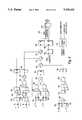
- FIG. 3A block diagram of a preferred embodiment of the simplified FIR filter for delay interpolation is shown in FIG. 3.
- the multipliers of FIG. 2are replaced by a series of multiplexers and bit shifters.
- the multiplexersare controlled by control bits rather than filter coefficients.
- the circuits of FIGS. 2 and 3produce the same result.
- the registers 50, 52, 54, 56, 58 and 60 shown in FIG. 2 for storing input data samplesare omitted from FIG. 3 for simplicity, but are required to provide input data samples to the FIR digital filter.
- the C and D data samplesare supplied to the respective inputs of a 2:1 multiplexer 102.
- Multiplexer 102 and the other multiplexers shown in FIG. 3 and described belowhave N bits per input and an N bit output, where N is the number of bits in the digital data sample.
- the multiplexer 102is controlled by a Q control bit.
- the output of multiplexer 102is supplied to a bit shifter 104.
- the bit shifter 104provides a times 1 output and a times 1/2 output to the respective inputs of a multiplexer 106.
- the multiplexer 106is controlled by an R control bit.
- the output of multiplexer 106is supplied to a register 108.
- bit shifter 104 and the other bit shifters shown in FIG. 3are implemented simply by appropriate connections to effect a right shift of the digital data sample.
- bit shifter 104the times 1 output is provided by connecting the bits of the data sample directly to the input of multiplexer 106 without shifting.
- the times 1/2 outputis provided by connecting the bits of the data sample to the inputs of multiplexer 106 with a one bit shift to the right.
- times 1/4is obtained by shifting the bits of the data sample two bits to the right
- times 1/8is obtained by shifting the bits of the data sample three bits to the right.
- multiplication by a filter coefficient of the form 1/2 mis implemented by shifting the bits of the data sample m bit positions to the right.
- Negative values, such as minus 1/4,are obtained by a logical inversion of the bits of the data sample and a shift to the right by the appropriate number of bits.
- the C and D data samplesare supplied to the respective inputs of a multiplexer 110 which is controlled by an X control bit.
- the output of multiplexer 110is supplied to a bit shifter 112 and to one input of a summing unit 114.
- the bit shifter 112supplies a times 0 output and a times 1/2 output to the respective inputs of a multiplexer 116.
- the multiplexer 116is controlled by an S control bit.
- the times 0 output of bit shifter 112indicates that all zero bit values are supplied to one of the inputs of multiplexer 116.
- the output of multiplexer 116is ANDed with a Y control bit in an AND gate 118.
- the AND gate 118comprises N gates for ANDing the N bits of the data sample with the Y control bit.
- the output of gate 118is supplied to the other input of summing unit 114.
- the output of summing unit 114is supplied to a register 120.
- the B data samplesare supplied to a bit shifter 126 which provides times minus 1/4 and times minus 1/8 outputs to the respective inputs of a multiplexer 128.
- the multiplexer 128is controlled by a T control bit.
- the output of multiplexer 128is ANDed with a U control bit in an N bit AND gate 130.
- the output of gate 130is supplied to one input of a summing unit 132.
- the E data samplesare supplied through a bit shifter 140 which provides times minus 1/4 and times minus 1/8 outputs to the respective inputs of a multiplexer 142.
- the multiplexer 142is controlled by a V control bit.
- the output of multiplexer 142is ANDed with the U control bit in an N bit AND gate 144.
- the output of AND gate 144is supplied to the other input of summing unit 132.
- the output of summing unit 132is supplied to a register 146.
- the A data samplesare supplied to a bit shifter 150 which provides a times 1/8 output to one input of a summing unit 152.
- the F data samplesare supplied to a bit shifter 152 which provides a times 1/8 output to the other output of the summing unit 152.
- the output of summing unit 152is supplied to a bit shifter 156 which provides times 1 and times 1/2 outputs to the respective inputs of a multiplexer 160.
- Multiplexer 160is controlled by a W control bit.
- the output of multiplexer 160is ANDed with the U control bit in an N bit AND gate 162.
- the output of AND gate 162is supplied to a register 164.
- the multiplexers 102, 106, 110, 116, 128, 142 and 160, the bit shifters 104, 112, 126, 140, 150, 154 and 156, the summing units 114,132 and 152 and the AND gates 118, 130, 144 and 162implement multiplication of the input data samples A, B, C, D, E and F by the coefficients C A , C B , C C , C E and C F , respectively, as shown in Table I, without the use of multipliers,
- control bits Q, R, S, T, U, V, W, X and Yare stored in a control RAM 170 which is addressed by the subdelay control signal.
- the control bits to implement delays of 0, 1/4, 1/2 and 3/4 of the sampling period with the circuit shown in FIG. 3are shown in Table II below.
- the outputs of registers 146 and 164are summed by a summing unit 172.
- the output of register 108 and the output of summing unit 172are summed by a summing unit 174.
- the output of register 120 and the output of summing unit 174are summed by a summing unit 176.
- the output of summing unit 176is supplied to a register 180.
- the FIR digital filterhas a different gain for each selected delay.
- the gainis corrected by a gain correction multiplier 184.
- the summing units 172, 174 and 176correspond to the summing unit 86 shown in FIG. 2.
- the gain correction multiplier 184receives the output data sample of the FIR filter from register 180.
- the gain correction value stored in control RAM 170is supplied to gain correction multiplier 184 through registers 186 and 188.
- the output of gain correction multiplier 184which is the gain corrected output data sample, is stored in a register 190.
- the required gain correction valuesare shown in Table I.
- Tables I and IIcontain different sets of coefficients and control bits, respectively, for a high band delay of 1/2 the sampling period. These values are used when the highest frequency components of the received signal are close to 1/2 the sampling rate. The different values are required because the FIR digital filter amplitude response rolls off at high frequencies.
- the high band coefficientsboost the high frequency response of the FIR digital filter at the expense of ripple in the pass band.
- the sampling rateis 40 MHz
- the standard coefficientscan be utilized for received signals having frequency components up to about 12 MHz.
- the high band coefficientsextend the usable range up to about 15 MHz.
- the FIR digital filter with six stagesprovides satisfactory operation when the highest component frequency of the received signal is no greater than about 3/8 of the sampling rate. For operation close to 1/2 of the sampling rate, an FIR digital filter with more than six stages is required.
- the delay interpolator shown in FIG. 3 and described abovehas a pipeline structure for high speed operation.
- the pipeline structurepermits operation at a typical clock frequency of 40 MHz.
- different stagesperform different operations simultaneously.
- the operations required to multiply the input data samples by the filter coefficients (without the use of multipliers in FIG. 3)are performed in a first pipeline stage, and the results are stored in pipeline registers 108, 120, 146 and 164.
- the summation of the multiplied valuesis performed in a second pipeline stage by summing units 172, 174 and 176, and the results are stored in pipeline register 180.
- the gain correctionis performed in a third pipeline stage by gain correction multiplier 184, and the results are stored in pipeline register 190.
- the registers 186 and 188synchronize the control bits supplied to the first pipeline stage with the gain correction values supplied to the third pipeline stage. For a given set of data values, multiplication is performed in the first pipeline stage during a first clock cycle, summation is performed in the second pipeline stage during a second clock cycle, and gain correction is performed in the third pipeline stage during a third clock cycle. Operations are performed simultaneously by each stage on different sets of data values to provide high speed operation. It will be understood that pipeline operation may not be necessary for operation at lower sampling rates.
- the delay interpolator shown in FIG. 3 and described aboveis preferably implemented in a large scale integrated circuit using commercially available logic optimization software. It will be understood that the actual circuit configuration after logic optimization may differ from that shown in FIG. 3, but will implement the set of filter coefficients listed in Table I. In general, many different circuits may be used to implement the set of filter coefficients listed in Table I, and the circuit shown in FIG. 3 is only one example. Furthermore, other sets of filter coefficients may be utilized within the scope of the present invention. The important point is that filter coefficients of the form 1/2 m can be implemented without the use of multipliers, thereby simplifying the required circuitry.
- the present inventionwhich comprises an FIR digital filter with selectable delays for delay interpolation, has been described in connection with formation of a single receive beam.
- the FIR digital filter delay interpolatoris used in a time multiplexed parallel beamformer.
- the time multiplexed parallel beamformeris used to form two or more receive beams simultaneously rather than replicating the beamformer circuitry for parallel operation.
- the single beamformeris operated in a time multiplexed manner to form multiple beams simultaneously.
- a sample of a first beamis processed during a first clock cycle
- a sample of a second beamis processed during a second clock cycle
- a sample of a third beamis processed during a third clock cycle
- a sample of a fourth beamis processed during a fourth clock cycle
- a second sample of the first beamis processed during a fifth clock cycle, etc.
- the FIR digital filter delay interpolatorcan be utilized in a time multiplexed beamformer for simultaneous processing of multiple beams because it does not contain internal feedback.
- An infinite impulse response (IIR) digital filterwould not be suitable for this application because it contains feedback.
- the FIR digital filter shown in FIG. 3 and described abovecan be used in a time multiplexed beamformer.
- the circuitry of the first pipeline stageperforms operations (multiplication of input samples by filter coefficients) for a first beam
- the second pipeline stageperforms summation operations for a second beam
- the third pipeline stageperforms gain correction operations for a third beam, all operations occurring simultaneously. Since there is no feedback in the FIR digital filter, the data for each beam is processed independently.
- FIG. 4A circuit for supplying groups of input data samples to the FIR filter for time multiplexed operation is shown in FIG. 4.
- the input data samplesare time multiplexed for four beams as a result of different delays applied by coarse delay 22 (FIG. 1) to data samples in different time slots.
- Each beamhas a separate set of delays for steering and focusing the beam to a desired point.
- the time multiplexed input data samplesare synchronized to an Interleave State signal, which may be two bits for a four beam system.
- the Interleave State signalis decoded by a two-to-four line decoder to provide enable signals EN1, EN2, EN3 and EN4.
- the enable signalsindicate which beam is being processed at any instant of time. Thus, for example, when enable signal EN1 is active, the input data sample represents the first beam.
- the data samplesare input in parallel to shift registers 204, 206, 208 and 210. Each of the shift registers includes six stages, each of N bits, where N is the number of bits in each data sample.
- the shifting of data samples into registers 204, 206, 208 and 210is controlled by enable signals EN1, EN2, EN3 and EN4.
- enable signal EN1is active, and a data sample representative of a first beam is loaded into register 204.
- enable signal EN2is active, and a data sample representative of a second beam is loaded into shift register 206.
- enable signal EN3is active, and a data sample representative of a third beam is loaded into shift register 208.
- enable signal EN4is active, and a data sample representative of a fourth beam is loaded into shift register 210. This process is repeated continuously so that each of the shift registers contains six consecutive samples of one of the four beams.
- register 204contains six consecutive samples of the first beam
- register 206contains six consecutive samples of the second beam, etc.
- the outputs of registers 204, 206, 208 and 210are supplied to four-to-one multiplexer 214.
- Each of the four inputs of multiplexer 214contains six data samples, each of N bits.
- the multiplexer 214is controlled by the Interleave State signal.
- the output of multiplexer 214is six data samples A-F, each of N bits, representative of one of the time multiplexed beams.
- the data samples A-F from multiplexer 214are supplied to the inputs of the FIR digital filter delay interpolator (FIG. 2 or FIG. 3). Thus, time multiplexed data is supplied to the inputs of the delay interpolator.
Landscapes
- Engineering & Computer Science (AREA)
- Physics & Mathematics (AREA)
- Acoustics & Sound (AREA)
- Multimedia (AREA)
- Computer Networks & Wireless Communication (AREA)
- General Physics & Mathematics (AREA)
- Radar, Positioning & Navigation (AREA)
- Remote Sensing (AREA)
- Ultra Sonic Daignosis Equipment (AREA)
Abstract
Description
TABLE I ______________________________________ GAIN COR- COEFFICIENTS DELAY RECTION C.sub.A C.sub.B C.sub.C C.sub.D C.sub.E C.sub.F ______________________________________ 0 0.5 0 0 2 0 0 0 1/4f 1/0.84 1/16 -1/4 3/2 1/2 -1/8 1/16 1/2f 1/0.79 1/16 -1/4 1 1 -1/4 1/16 3/4f 1/0.84 1/16 -1/8 1/2 3/2 -1/4 1/16 1/2f 1/8 -1/4 1 1 -1/4 1/8 (Hiband) ______________________________________
TABLE II ______________________________________ CONTROL BITS DELAY Q R S T U V W X Y ______________________________________ 0 0 0 0 0 0 0 0 0 0 1/4f 1 1 1 0 1 1 1 0 1 1/2f 0 0 0 0 1 0 1 1 0 3/4f 0 1 1 1 1 0 1 1 1 1/2f (Hiband) 0 0 0 0 1 0 0 1 0 ______________________________________
Claims (13)
Priority Applications (3)
| Application Number | Priority Date | Filing Date | Title |
|---|---|---|---|
| US08/060,789US5345426A (en) | 1993-05-12 | 1993-05-12 | Delay interpolator for digital phased array ultrasound beamformers |
| DE4402098ADE4402098C2 (en) | 1993-05-12 | 1994-01-25 | Ultrasonic beam former |
| JP09864194AJP3442471B2 (en) | 1993-05-12 | 1994-05-12 | Delay interpolator for digital phased array type ultrasonic beamformer |
Applications Claiming Priority (1)
| Application Number | Priority Date | Filing Date | Title |
|---|---|---|---|
| US08/060,789US5345426A (en) | 1993-05-12 | 1993-05-12 | Delay interpolator for digital phased array ultrasound beamformers |
Publications (1)
| Publication Number | Publication Date |
|---|---|
| US5345426Atrue US5345426A (en) | 1994-09-06 |
Family
ID=22031766
Family Applications (1)
| Application Number | Title | Priority Date | Filing Date |
|---|---|---|---|
| US08/060,789Expired - LifetimeUS5345426A (en) | 1993-05-12 | 1993-05-12 | Delay interpolator for digital phased array ultrasound beamformers |
Country Status (3)
| Country | Link |
|---|---|
| US (1) | US5345426A (en) |
| JP (1) | JP3442471B2 (en) |
| DE (1) | DE4402098C2 (en) |
Cited By (102)
| Publication number | Priority date | Publication date | Assignee | Title |
|---|---|---|---|---|
| US5469851A (en)* | 1994-08-09 | 1995-11-28 | Hewlett-Packard Company | Time multiplexed digital ultrasound beamformer |
| US5490511A (en)* | 1992-01-14 | 1996-02-13 | Ge Yokogawa Medical Systems, Ltd | Digital phase shifting apparatus |
| US5522391A (en)* | 1994-08-09 | 1996-06-04 | Hewlett-Packard Company | Delay generator for phased array ultrasound beamformer |
| US5544655A (en)* | 1994-09-16 | 1996-08-13 | Atlantis Diagnostics International, Llc | Ultrasonic multiline beamforming with interleaved sampling |
| US5573001A (en)* | 1995-09-08 | 1996-11-12 | Acuson Corporation | Ultrasonic receive beamformer with phased sub-arrays |
| US5589636A (en)* | 1994-04-22 | 1996-12-31 | Sonident Anstalt Liechtensteinischen Rechts | Method of and apparatus for the detection of an ultrasonic field |
| US5590658A (en)* | 1995-06-29 | 1997-01-07 | Teratech Corporation | Portable ultrasound imaging system |
| GB2307042A (en)* | 1995-11-10 | 1997-05-14 | Bae Sema Ltd | Sonar signal processing apparatus |
| US5685308A (en)* | 1994-08-05 | 1997-11-11 | Acuson Corporation | Method and apparatus for receive beamformer system |
| US5797847A (en)* | 1996-12-30 | 1998-08-25 | General Electric Company | Method and apparatus for complex bandpass filtering and decimation in ultrasound beamformer |
| US5844139A (en)* | 1996-12-30 | 1998-12-01 | General Electric Company | Method and apparatus for providing dynamically variable time delays for ultrasound beamformer |
| US5905692A (en)* | 1997-12-31 | 1999-05-18 | Analogic Corporation | Digital ultrasound beamformer |
| WO1999033400A1 (en)* | 1997-12-31 | 1999-07-08 | Analogic Corporation | Method and apparatus for delaying ultrasound signals |
| US5921932A (en)* | 1994-08-05 | 1999-07-13 | Acuson Corporation | Method and apparatus for a baseband processor of a receive beamformer system |
| US5940123A (en)* | 1997-02-13 | 1999-08-17 | Atl Ultrasound | High resolution ultrasonic imaging through interpolation of received scanline data |
| US5957846A (en)* | 1995-06-29 | 1999-09-28 | Teratech Corporation | Portable ultrasound imaging system |
| US5964709A (en)* | 1995-06-29 | 1999-10-12 | Teratech Corporation | Portable ultrasound imaging system |
| US5976089A (en)* | 1998-03-24 | 1999-11-02 | Hewlett-Packard Company | Increasing the frame rate of a phased array imaging system |
| US5997479A (en)* | 1998-05-28 | 1999-12-07 | Hewlett-Packard Company | Phased array acoustic systems with intra-group processors |
| US6016285A (en)* | 1994-08-05 | 2000-01-18 | Acuson Corporation | Method and apparatus for coherent image formation |
| US6029116A (en)* | 1994-08-05 | 2000-02-22 | Acuson Corporation | Method and apparatus for a baseband processor of a receive beamformer system |
| US6228030B1 (en) | 1998-06-24 | 2001-05-08 | Ecton, Inc. | Method of using ultrasound energy to locate the occurrence of predetermined event in the heart cycle or other physiologic cycle of the body |
| US6248073B1 (en) | 1995-06-29 | 2001-06-19 | Teratech Corporation | Ultrasound scan conversion with spatial dithering |
| USD445189S1 (en) | 1999-09-14 | 2001-07-17 | Ecton, Inc. | Medical diagnostic ultrasound system |
| US6312381B1 (en) | 1999-09-14 | 2001-11-06 | Acuson Corporation | Medical diagnostic ultrasound system and method |
| US6436039B1 (en) | 1999-09-14 | 2002-08-20 | Ecton, Inc. | Medicial diagnostic ultrasound system and method |
| US6468213B1 (en) | 1999-09-14 | 2002-10-22 | Ecton, Inc. | Medical diagnostic ultrasound system and method |
| US6488625B1 (en) | 1999-09-14 | 2002-12-03 | Ecton, Inc. | Medical diagnostic ultrasound system and method |
| US6491634B1 (en) | 2000-10-13 | 2002-12-10 | Koninklijke Philips Electronics N.V. | Sub-beamforming apparatus and method for a portable ultrasound imaging system |
| US6497664B1 (en) | 1999-09-14 | 2002-12-24 | Ecton, Inc. | Medical diagnostic ultrasound system and method |
| US6500120B1 (en) | 2001-07-31 | 2002-12-31 | Koninklijke Philips Electronics N.V. | Beamforming system using analog random access memory |
| US6508763B1 (en) | 1999-09-14 | 2003-01-21 | Ecton, Inc. | Medical diagnostic ultrasound system and method |
| WO2003011139A1 (en) | 2001-07-31 | 2003-02-13 | Koninklijke Philips Electronics N.V. | Transesophageal and transnasal, transesophageal ultrasound imaging systems |
| US6524244B1 (en) | 1999-09-14 | 2003-02-25 | Ecton Inc. | Medical diagnostic ultrasound system and method |
| US6561979B1 (en) | 1999-09-14 | 2003-05-13 | Acuson Corporation | Medical diagnostic ultrasound system and method |
| US6572547B2 (en) | 2001-07-31 | 2003-06-03 | Koninklijke Philips Electronics N.V. | Transesophageal and transnasal, transesophageal ultrasound imaging systems |
| US20040019277A1 (en)* | 2002-07-23 | 2004-01-29 | Medison Co., Ltd. | Digital receive-focusing apparatus using analogue multiplexers |
| US6695783B2 (en) | 2000-12-22 | 2004-02-24 | Koninklijke Philips Electronics N.V. | Multiline ultrasound beamformers |
| WO2004031802A1 (en)* | 2002-10-04 | 2004-04-15 | Koninklijke Philips Electronics N.V. | Method and apparatus for 1d array ultrasound probe |
| US20040104839A1 (en)* | 1996-10-10 | 2004-06-03 | Teratech Corporation | Communication system using geographic position data |
| EP1027771A4 (en)* | 1997-10-06 | 2004-07-14 | Q Dot Inc | Beamformed ultrasonic imager with delta-sigma feedback control |
| US20040170223A1 (en)* | 2003-03-02 | 2004-09-02 | Tzi-Dar Chiueh | Reconfigurable fir filter |
| US20050072227A1 (en)* | 2003-10-01 | 2005-04-07 | Flowline Inc. | Depth determining system |
| US20050113694A1 (en)* | 2003-11-21 | 2005-05-26 | Haugen Geir U. | Ultrasound probe distributed beamformer |
| US20050113698A1 (en)* | 2003-11-21 | 2005-05-26 | Kjell Kristoffersen | Ultrasound probe transceiver circuitry |
| US20050113699A1 (en)* | 2003-11-21 | 2005-05-26 | Haugen Geir U. | Ultrasound probe sub-aperture processing |
| US20060064015A1 (en)* | 2004-09-20 | 2006-03-23 | Davies Timothy J | Systems and methods for improved imaging |
| US7065052B1 (en)* | 1998-07-22 | 2006-06-20 | Alcatel Canada Inc. | Cell stream replicating device |
| CN1307427C (en)* | 2002-08-28 | 2007-03-28 | 深圳迈瑞生物医疗电子股份有限公司 | Beam synthesizer and synthetic method based on linear interpolation |
| CN100337595C (en)* | 2004-06-18 | 2007-09-19 | 深圳迈瑞生物医疗电子股份有限公司 | Beam composition method and device based on null aim interpolation |
| US20070239001A1 (en)* | 2005-11-02 | 2007-10-11 | James Mehi | High frequency array ultrasound system |
| US20080255451A1 (en)* | 2007-04-10 | 2008-10-16 | C.R. Bard, Inc. | Low power ultrasound system |
| US20090018443A1 (en)* | 2007-07-12 | 2009-01-15 | Colby Brian V | System for generating multiple beams from a single receive event |
| US7500952B1 (en) | 1995-06-29 | 2009-03-10 | Teratech Corporation | Portable ultrasound imaging system |
| US20090303838A1 (en)* | 2005-06-29 | 2009-12-10 | Oceanscan Limited | Acoustic Sensor and Method |
| US7678048B1 (en) | 1999-09-14 | 2010-03-16 | Siemens Medical Solutions Usa, Inc. | Medical diagnostic ultrasound system and method |
| US20100121196A1 (en)* | 1996-06-28 | 2010-05-13 | Sonosite, Inc. | Ultrasonic Signal Processor for a Hand Held Ultrasonic Diagnostic Instrument |
| WO2010097710A1 (en)* | 2009-02-27 | 2010-09-02 | Dalhousie University | High-frequency ultrasound imaging system |
| US20100228130A1 (en)* | 2009-03-09 | 2010-09-09 | Teratech Corporation | Portable ultrasound imaging system |
| US20100251046A1 (en)* | 2006-08-24 | 2010-09-30 | Masayuki Mizuno | Failure prediction circuit and method, and semiconductor integrated circuit |
| US7819805B2 (en) | 2004-09-20 | 2010-10-26 | Mgb Investments Limited Partnership | Sub-nyquist sampling of acoustic signals in ultrasound imaging |
| US7830069B2 (en) | 2004-04-20 | 2010-11-09 | Sunnybrook Health Sciences Centre | Arrayed ultrasonic transducer |
| US20110071395A1 (en)* | 2001-07-31 | 2011-03-24 | Koninklijke Philips Electronics N.V. | Transesophageal and transnasal, transesophageal ultrasound imaging systems |
| US20110125017A1 (en)* | 2004-09-20 | 2011-05-26 | Innervision Medical Technologies Inc. | Systems and Methods for Ultrasound Imaging |
| US8052606B2 (en) | 1996-06-28 | 2011-11-08 | Sonosite, Inc. | Balance body ultrasound system |
| US8241217B2 (en) | 1995-06-29 | 2012-08-14 | Teratech Corporation | Portable ultrasound imaging data |
| US8316518B2 (en) | 2008-09-18 | 2012-11-27 | Visualsonics Inc. | Methods for manufacturing ultrasound transducers and other components |
| US9072495B2 (en) | 2006-10-25 | 2015-07-07 | Maui Imaging, Inc. | Method and apparatus to produce ultrasonic images using multiple apertures |
| US9146313B2 (en) | 2006-09-14 | 2015-09-29 | Maui Imaging, Inc. | Point source transmission and speed-of-sound correction using multi-aperature ultrasound imaging |
| US9173047B2 (en) | 2008-09-18 | 2015-10-27 | Fujifilm Sonosite, Inc. | Methods for manufacturing ultrasound transducers and other components |
| US9184369B2 (en) | 2008-09-18 | 2015-11-10 | Fujifilm Sonosite, Inc. | Methods for manufacturing ultrasound transducers and other components |
| US9192355B2 (en) | 2006-02-06 | 2015-11-24 | Maui Imaging, Inc. | Multiple aperture ultrasound array alignment fixture |
| US9220478B2 (en) | 2010-04-14 | 2015-12-29 | Maui Imaging, Inc. | Concave ultrasound transducers and 3D arrays |
| US9265484B2 (en) | 2011-12-29 | 2016-02-23 | Maui Imaging, Inc. | M-mode ultrasound imaging of arbitrary paths |
| US9282945B2 (en) | 2009-04-14 | 2016-03-15 | Maui Imaging, Inc. | Calibration of ultrasound probes |
| US9339256B2 (en) | 2007-10-01 | 2016-05-17 | Maui Imaging, Inc. | Determining material stiffness using multiple aperture ultrasound |
| US9510806B2 (en) | 2013-03-13 | 2016-12-06 | Maui Imaging, Inc. | Alignment of ultrasound transducer arrays and multiple aperture probe assembly |
| US9572549B2 (en) | 2012-08-10 | 2017-02-21 | Maui Imaging, Inc. | Calibration of multiple aperture ultrasound probes |
| US9582876B2 (en) | 2006-02-06 | 2017-02-28 | Maui Imaging, Inc. | Method and apparatus to visualize the coronary arteries using ultrasound |
| US9645121B2 (en) | 2013-05-07 | 2017-05-09 | Industrial Technology Research Institute | Nonlinear dynamic focusing control method |
| US9668714B2 (en) | 2010-04-14 | 2017-06-06 | Maui Imaging, Inc. | Systems and methods for improving ultrasound image quality by applying weighting factors |
| US9788813B2 (en) | 2010-10-13 | 2017-10-17 | Maui Imaging, Inc. | Multiple aperture probe internal apparatus and cable assemblies |
| US9883848B2 (en) | 2013-09-13 | 2018-02-06 | Maui Imaging, Inc. | Ultrasound imaging using apparent point-source transmit transducer |
| WO2018041644A1 (en)* | 2016-09-02 | 2018-03-08 | Koninklijke Philips N.V. | Ultrasound probe with digital microbeamformer using fir filters with no multipliers |
| WO2018060820A1 (en) | 2016-09-29 | 2018-04-05 | Koninklijke Philips N.V. | Ultrasonic shear wave imaging with background motion compensation |
| US9986969B2 (en) | 2012-09-06 | 2018-06-05 | Maui Imaging, Inc. | Ultrasound imaging system memory architecture |
| US10226234B2 (en) | 2011-12-01 | 2019-03-12 | Maui Imaging, Inc. | Motion detection using ping-based and multiple aperture doppler ultrasound |
| WO2019072552A1 (en) | 2017-10-12 | 2019-04-18 | Koninklijke Philips N.V. | Ultrasonic shearwave imaging with patient-adaptive shearwave generation |
| CN109804268A (en)* | 2016-09-02 | 2019-05-24 | 皇家飞利浦有限公司 | Ultrasonic probe with multi-thread digital microwave beamformer |
| US10368843B2 (en) | 2009-11-25 | 2019-08-06 | Koninklijke Philips N.V. | Ultrasonic shear wave imaging with focused scanline beamforming |
| US10401493B2 (en) | 2014-08-18 | 2019-09-03 | Maui Imaging, Inc. | Network-based ultrasound imaging system |
| US10405829B2 (en) | 2014-12-01 | 2019-09-10 | Clarius Mobile Health Corp. | Ultrasound machine having scalable receive beamformer architecture comprising multiple beamformers with common coefficient generator and related methods |
| WO2019179758A1 (en) | 2018-03-21 | 2019-09-26 | Koninklijke Philips N.V. | Ultrasound system for shear wave imaging in three dimensions |
| WO2019192970A1 (en) | 2018-04-02 | 2019-10-10 | Koninklijke Philips N.V. | Ultrasonic shear wave imaging with improved accuracy and reliability |
| US10613205B2 (en) | 2014-10-06 | 2020-04-07 | Analog Devices, Inc. | Systems and methods for ultrasound beamforming |
| US10856846B2 (en) | 2016-01-27 | 2020-12-08 | Maui Imaging, Inc. | Ultrasound imaging with sparse array probes |
| US11129595B2 (en)* | 2014-10-31 | 2021-09-28 | Canon Medical Systems Corporation | Ultrasonic diagnostic apparatus, interpolation processing unit, and interpolation processing method |
| US11249188B2 (en) | 2015-12-30 | 2022-02-15 | Koninklijke Philips N.V. | System and method for dynamic filtering |
| US12023201B2 (en) | 2020-04-22 | 2024-07-02 | Bfly Operations, Inc. | Methods and apparatuses for beamforming in ultrasound systems using unbuffered data samples |
| US20240322431A1 (en)* | 2021-02-24 | 2024-09-26 | Bluehalo, Llc | System and method for a digitally beamformed phased array feed |
| US12167209B2 (en) | 2012-09-06 | 2024-12-10 | Maui Imaging, Inc. | Ultrasound imaging system memory architecture |
| US12190627B2 (en) | 2015-03-30 | 2025-01-07 | Maui Imaging, Inc. | Ultrasound imaging systems and methods for detecting object motion |
Families Citing this family (5)
| Publication number | Priority date | Publication date | Assignee | Title |
|---|---|---|---|---|
| KR100350026B1 (en) | 2000-06-17 | 2002-08-24 | 주식회사 메디슨 | Ultrasound imaging method and apparatus based on pulse compression technique using a spread spectrum signal |
| KR100901787B1 (en)* | 2006-12-15 | 2009-06-11 | 서강대학교기술지주 주식회사 | Fractional Delay Filter-Based Beam Focusing Device and Method Using Post Filtering |
| US9007872B2 (en)* | 2009-02-06 | 2015-04-14 | Hitachi Medical Corporation | Ultrasonic diagnostic apparatus and method thereof |
| DE102011088346B4 (en)* | 2011-12-13 | 2022-01-05 | Robert Bosch Gmbh | Device for detecting acoustic signals and the associated method |
| KR102591262B1 (en)* | 2021-12-27 | 2023-10-19 | 강원대학교산학협력단 | Apparatus and mehod for making ultrasound imaging |
Citations (12)
| Publication number | Priority date | Publication date | Assignee | Title |
|---|---|---|---|---|
| US4170766A (en)* | 1978-01-27 | 1979-10-09 | Raytheon Company | Beamformer |
| US4213195A (en)* | 1976-04-12 | 1980-07-15 | Raytheon Company | Sonic direction system |
| US4290127A (en)* | 1979-12-03 | 1981-09-15 | Raytheon Company | Beamformer with reduced sampling rate |
| US4336607A (en)* | 1980-12-10 | 1982-06-22 | The United States Of America As Represented By The Secretary Of The Navy | Beamformer having random access memory delay |
| US4626217A (en)* | 1983-05-02 | 1986-12-02 | Raytheon Company | Broadband doppler simulator |
| US4688045A (en)* | 1985-03-21 | 1987-08-18 | Knudsen Donald C | Digital delay generator for sonar and radar beam formers |
| US4779622A (en)* | 1986-07-07 | 1988-10-25 | Matsushita Electric Industrial Co., Ltd. | Ultrasonic wave diagnostic apparatus employing interpolated values of weighting data |
| US4787392A (en)* | 1986-05-16 | 1988-11-29 | Siemens Aktiengesellschaft | Method and apparatus for digital delay of ultrasound signals upon reception thereof |
| US4920521A (en)* | 1987-02-24 | 1990-04-24 | Kabushiki Kaisha Toshiba | Method and system for interpolation-processing delay time data |
| US4969132A (en)* | 1987-05-21 | 1990-11-06 | Hughes Aircarft Company | Delay quantization technique to reduce steering errors in digital beamformers |
| US5088496A (en)* | 1989-09-29 | 1992-02-18 | U.S. Philips Corporation | Ultrasonic echography apparatus utilizing a digital device for forming channels, in the receiving mode |
| US5191546A (en)* | 1991-01-22 | 1993-03-02 | The United States Of America As Represented By The Secretary Of The Navy | Time-interpolation method for digital beamformers |
Family Cites Families (13)
| Publication number | Priority date | Publication date | Assignee | Title |
|---|---|---|---|---|
| NL168669C (en) | 1974-09-16 | 1982-04-16 | Philips Nv | INTERPOLING DIGITAL FILTER WITH INPUT BUFFER. |
| US3997772A (en) | 1975-09-05 | 1976-12-14 | Bell Telephone Laboratories, Incorporated | Digital phase shifter |
| US4116229A (en)* | 1976-08-30 | 1978-09-26 | Hewlett-Packard Company | Acoustic imaging apparatus |
| JPS6222632A (en)* | 1985-07-22 | 1987-01-30 | 株式会社東芝 | electronic focus device |
| JPS63222745A (en)* | 1987-03-13 | 1988-09-16 | 松下電器産業株式会社 | Ultrasound diagnostic equipment |
| JPH02206445A (en)* | 1989-02-03 | 1990-08-16 | Toshiba Corp | Ultrasonic diagnostic apparatus |
| JP2775312B2 (en)* | 1989-09-18 | 1998-07-16 | ジーイー横河メディカルシステム株式会社 | Receiving digital beamformer for phased array type ultrasonic equipment. |
| JP2856858B2 (en)* | 1990-07-30 | 1999-02-10 | 株式会社東芝 | Ultrasound diagnostic equipment |
| JPH084588B2 (en)* | 1991-07-02 | 1996-01-24 | 富士通株式会社 | Ultrasonic receiver |
| JP3283053B2 (en)* | 1992-01-14 | 2002-05-20 | ジーイー横河メディカルシステム株式会社 | Digital phase shifter and ultrasonic diagnostic equipment |
| JPH05243907A (en)* | 1992-02-28 | 1993-09-21 | Victor Co Of Japan Ltd | Sampling rate converting device |
| JP3089104B2 (en)* | 1992-06-19 | 2000-09-18 | 株式会社日立製作所 | Moving average filter and A / D converter using the same |
| US5388079A (en) | 1993-03-26 | 1995-02-07 | Siemens Medical Systems, Inc. | Partial beamforming |
- 1993
- 1993-05-12USUS08/060,789patent/US5345426A/ennot_activeExpired - Lifetime
- 1994
- 1994-01-25DEDE4402098Apatent/DE4402098C2/ennot_activeExpired - Lifetime
- 1994-05-12JPJP09864194Apatent/JP3442471B2/ennot_activeExpired - Lifetime
Patent Citations (12)
| Publication number | Priority date | Publication date | Assignee | Title |
|---|---|---|---|---|
| US4213195A (en)* | 1976-04-12 | 1980-07-15 | Raytheon Company | Sonic direction system |
| US4170766A (en)* | 1978-01-27 | 1979-10-09 | Raytheon Company | Beamformer |
| US4290127A (en)* | 1979-12-03 | 1981-09-15 | Raytheon Company | Beamformer with reduced sampling rate |
| US4336607A (en)* | 1980-12-10 | 1982-06-22 | The United States Of America As Represented By The Secretary Of The Navy | Beamformer having random access memory delay |
| US4626217A (en)* | 1983-05-02 | 1986-12-02 | Raytheon Company | Broadband doppler simulator |
| US4688045A (en)* | 1985-03-21 | 1987-08-18 | Knudsen Donald C | Digital delay generator for sonar and radar beam formers |
| US4787392A (en)* | 1986-05-16 | 1988-11-29 | Siemens Aktiengesellschaft | Method and apparatus for digital delay of ultrasound signals upon reception thereof |
| US4779622A (en)* | 1986-07-07 | 1988-10-25 | Matsushita Electric Industrial Co., Ltd. | Ultrasonic wave diagnostic apparatus employing interpolated values of weighting data |
| US4920521A (en)* | 1987-02-24 | 1990-04-24 | Kabushiki Kaisha Toshiba | Method and system for interpolation-processing delay time data |
| US4969132A (en)* | 1987-05-21 | 1990-11-06 | Hughes Aircarft Company | Delay quantization technique to reduce steering errors in digital beamformers |
| US5088496A (en)* | 1989-09-29 | 1992-02-18 | U.S. Philips Corporation | Ultrasonic echography apparatus utilizing a digital device for forming channels, in the receiving mode |
| US5191546A (en)* | 1991-01-22 | 1993-03-02 | The United States Of America As Represented By The Secretary Of The Navy | Time-interpolation method for digital beamformers |
Non-Patent Citations (6)
| Title |
|---|
| R. G. Pridham et al, "A Novel Approach to Digital Beamforming", J. Acoust. Soc. Am. 63(2), Feb. 1978, pp. 425-434. |
| R. G. Pridham et al, "Digital Interpolation Beamforming for Low-Pass & Bandpass Signals", IEEE Proceedings, vol. 67, No. 6, Jun. 1979, pp. 904-919. |
| R. G. Pridham et al, A Novel Approach to Digital Beamforming , J. Acoust. Soc. Am. 63(2), Feb. 1978, pp. 425 434.* |
| R. G. Pridham et al, Digital Interpolation Beamforming for Low Pass & Bandpass Signals , IEEE Proceedings, vol. 67, No. 6, Jun. 1979, pp. 904 919.* |
| T. K. Song et al, "A New Digital Phased Array System for Dynamic Focusing and Steering with Reduced Sampling Rate", Ultrasonic Imaging 12, 1-16, 1990. |
| T. K. Song et al, A New Digital Phased Array System for Dynamic Focusing and Steering with Reduced Sampling Rate , Ultrasonic Imaging 12, 1 16, 1990.* |
Cited By (180)
| Publication number | Priority date | Publication date | Assignee | Title |
|---|---|---|---|---|
| US5490511A (en)* | 1992-01-14 | 1996-02-13 | Ge Yokogawa Medical Systems, Ltd | Digital phase shifting apparatus |
| US5589636A (en)* | 1994-04-22 | 1996-12-31 | Sonident Anstalt Liechtensteinischen Rechts | Method of and apparatus for the detection of an ultrasonic field |
| US5685308A (en)* | 1994-08-05 | 1997-11-11 | Acuson Corporation | Method and apparatus for receive beamformer system |
| US6110116A (en)* | 1994-08-05 | 2000-08-29 | Acuson Corporation | Method and apparatus for receive beamformer system |
| US6042547A (en)* | 1994-08-05 | 2000-03-28 | Acuson Corporation | Method and apparatus for receive beamformer system |
| US6029116A (en)* | 1994-08-05 | 2000-02-22 | Acuson Corporation | Method and apparatus for a baseband processor of a receive beamformer system |
| US5882307A (en)* | 1994-08-05 | 1999-03-16 | Acuson Corporation | Method and apparatus for receive beamformer system |
| US6016285A (en)* | 1994-08-05 | 2000-01-18 | Acuson Corporation | Method and apparatus for coherent image formation |
| US5928152A (en)* | 1994-08-05 | 1999-07-27 | Acuson Corporation | Method and apparatus for a baseband processor of a receive beamformer system |
| US5827188A (en)* | 1994-08-05 | 1998-10-27 | Acuson Corporation | Method and apparatus for receive beamformer system |
| US5921932A (en)* | 1994-08-05 | 1999-07-13 | Acuson Corporation | Method and apparatus for a baseband processor of a receive beamformer system |
| US5469851A (en)* | 1994-08-09 | 1995-11-28 | Hewlett-Packard Company | Time multiplexed digital ultrasound beamformer |
| US5522391A (en)* | 1994-08-09 | 1996-06-04 | Hewlett-Packard Company | Delay generator for phased array ultrasound beamformer |
| EP0696792A3 (en)* | 1994-08-09 | 1998-06-17 | Hewlett-Packard Company | Time multiplexed digital ultrasound beamformer |
| US5544655A (en)* | 1994-09-16 | 1996-08-13 | Atlantis Diagnostics International, Llc | Ultrasonic multiline beamforming with interleaved sampling |
| US8628474B2 (en) | 1995-06-29 | 2014-01-14 | Teratech Corporation | Portable ultrasound imaging system |
| US6106472A (en)* | 1995-06-29 | 2000-08-22 | Teratech Corporation | Portable ultrasound imaging system |
| US20030028113A1 (en)* | 1995-06-29 | 2003-02-06 | Teratech Corporation | Ultrasound scan conversion with spatial dithering |
| US6379304B1 (en) | 1995-06-29 | 2002-04-30 | Teratech Corporation | Ultrasound scan conversion with spatial dithering |
| US6248073B1 (en) | 1995-06-29 | 2001-06-19 | Teratech Corporation | Ultrasound scan conversion with spatial dithering |
| US7500952B1 (en) | 1995-06-29 | 2009-03-10 | Teratech Corporation | Portable ultrasound imaging system |
| US8469893B2 (en) | 1995-06-29 | 2013-06-25 | Teratech Corp. | Portable ultrasound imaging system |
| US5590658A (en)* | 1995-06-29 | 1997-01-07 | Teratech Corporation | Portable ultrasound imaging system |
| US5957846A (en)* | 1995-06-29 | 1999-09-28 | Teratech Corporation | Portable ultrasound imaging system |
| US5964709A (en)* | 1995-06-29 | 1999-10-12 | Teratech Corporation | Portable ultrasound imaging system |
| US8241217B2 (en) | 1995-06-29 | 2012-08-14 | Teratech Corporation | Portable ultrasound imaging data |
| US5690114A (en)* | 1995-06-29 | 1997-11-25 | Teratech Corporation | Portable ultrasound imaging system |
| US5676147A (en)* | 1995-09-08 | 1997-10-14 | Acuson Corporation | Ultrasonic receive beamformer with phased sub-arrays |
| US5573001A (en)* | 1995-09-08 | 1996-11-12 | Acuson Corporation | Ultrasonic receive beamformer with phased sub-arrays |
| GB2307042B (en)* | 1995-11-10 | 1999-12-01 | Bae Sema Ltd | Improvements in sonar data processing |
| GB2307042A (en)* | 1995-11-10 | 1997-05-14 | Bae Sema Ltd | Sonar signal processing apparatus |
| US5864515A (en)* | 1995-11-10 | 1999-01-26 | Bae Sema Limited | Sonar data processing |
| US8216146B2 (en) | 1996-06-28 | 2012-07-10 | Sonosite, Inc. | Ultrasonic signal processor for a hand held ultrasonic diagnostic instrument |
| US20100121196A1 (en)* | 1996-06-28 | 2010-05-13 | Sonosite, Inc. | Ultrasonic Signal Processor for a Hand Held Ultrasonic Diagnostic Instrument |
| US8052606B2 (en) | 1996-06-28 | 2011-11-08 | Sonosite, Inc. | Balance body ultrasound system |
| US20040104839A1 (en)* | 1996-10-10 | 2004-06-03 | Teratech Corporation | Communication system using geographic position data |
| US5797847A (en)* | 1996-12-30 | 1998-08-25 | General Electric Company | Method and apparatus for complex bandpass filtering and decimation in ultrasound beamformer |
| US5844139A (en)* | 1996-12-30 | 1998-12-01 | General Electric Company | Method and apparatus for providing dynamically variable time delays for ultrasound beamformer |
| US5940123A (en)* | 1997-02-13 | 1999-08-17 | Atl Ultrasound | High resolution ultrasonic imaging through interpolation of received scanline data |
| EP1027771A4 (en)* | 1997-10-06 | 2004-07-14 | Q Dot Inc | Beamformed ultrasonic imager with delta-sigma feedback control |
| US5935070A (en)* | 1997-12-31 | 1999-08-10 | Analogic Corporation | Method and apparatus for delaying ultrasound signals |
| WO1999033400A1 (en)* | 1997-12-31 | 1999-07-08 | Analogic Corporation | Method and apparatus for delaying ultrasound signals |
| US5905692A (en)* | 1997-12-31 | 1999-05-18 | Analogic Corporation | Digital ultrasound beamformer |
| US5976089A (en)* | 1998-03-24 | 1999-11-02 | Hewlett-Packard Company | Increasing the frame rate of a phased array imaging system |
| US5997479A (en)* | 1998-05-28 | 1999-12-07 | Hewlett-Packard Company | Phased array acoustic systems with intra-group processors |
| US6228030B1 (en) | 1998-06-24 | 2001-05-08 | Ecton, Inc. | Method of using ultrasound energy to locate the occurrence of predetermined event in the heart cycle or other physiologic cycle of the body |
| US7065052B1 (en)* | 1998-07-22 | 2006-06-20 | Alcatel Canada Inc. | Cell stream replicating device |
| US6497664B1 (en) | 1999-09-14 | 2002-12-24 | Ecton, Inc. | Medical diagnostic ultrasound system and method |
| US6312381B1 (en) | 1999-09-14 | 2001-11-06 | Acuson Corporation | Medical diagnostic ultrasound system and method |
| US6561979B1 (en) | 1999-09-14 | 2003-05-13 | Acuson Corporation | Medical diagnostic ultrasound system and method |
| US6488625B1 (en) | 1999-09-14 | 2002-12-03 | Ecton, Inc. | Medical diagnostic ultrasound system and method |
| US6468213B1 (en) | 1999-09-14 | 2002-10-22 | Ecton, Inc. | Medical diagnostic ultrasound system and method |
| US6436039B1 (en) | 1999-09-14 | 2002-08-20 | Ecton, Inc. | Medicial diagnostic ultrasound system and method |
| USD454954S1 (en) | 1999-09-14 | 2002-03-26 | Ecton, Inc. | Medical diagnostic ultrasound system |
| US7678048B1 (en) | 1999-09-14 | 2010-03-16 | Siemens Medical Solutions Usa, Inc. | Medical diagnostic ultrasound system and method |
| US6508763B1 (en) | 1999-09-14 | 2003-01-21 | Ecton, Inc. | Medical diagnostic ultrasound system and method |
| US6524244B1 (en) | 1999-09-14 | 2003-02-25 | Ecton Inc. | Medical diagnostic ultrasound system and method |
| USD445189S1 (en) | 1999-09-14 | 2001-07-17 | Ecton, Inc. | Medical diagnostic ultrasound system |
| US6491634B1 (en) | 2000-10-13 | 2002-12-10 | Koninklijke Philips Electronics N.V. | Sub-beamforming apparatus and method for a portable ultrasound imaging system |
| US6695783B2 (en) | 2000-12-22 | 2004-02-24 | Koninklijke Philips Electronics N.V. | Multiline ultrasound beamformers |
| US20110071395A1 (en)* | 2001-07-31 | 2011-03-24 | Koninklijke Philips Electronics N.V. | Transesophageal and transnasal, transesophageal ultrasound imaging systems |
| WO2003011139A1 (en) | 2001-07-31 | 2003-02-13 | Koninklijke Philips Electronics N.V. | Transesophageal and transnasal, transesophageal ultrasound imaging systems |
| USRE45759E1 (en) | 2001-07-31 | 2015-10-20 | Koninklijke Philips N.V. | Transesophageal and transnasal, transesophageal ultrasound imaging systems |
| US6500120B1 (en) | 2001-07-31 | 2002-12-31 | Koninklijke Philips Electronics N.V. | Beamforming system using analog random access memory |
| US6679849B2 (en) | 2001-07-31 | 2004-01-20 | Koninklijke Philips Electronics N.V. | Ultrasonic tee probe with two dimensional array transducer |
| US6572547B2 (en) | 2001-07-31 | 2003-06-03 | Koninklijke Philips Electronics N.V. | Transesophageal and transnasal, transesophageal ultrasound imaging systems |
| US7993270B2 (en)* | 2002-07-23 | 2011-08-09 | Medison Co., Ltd. | Digital receive-focusing apparatus using analogue multiplexers |
| US20040019277A1 (en)* | 2002-07-23 | 2004-01-29 | Medison Co., Ltd. | Digital receive-focusing apparatus using analogue multiplexers |
| CN1307427C (en)* | 2002-08-28 | 2007-03-28 | 深圳迈瑞生物医疗电子股份有限公司 | Beam synthesizer and synthetic method based on linear interpolation |
| WO2004031802A1 (en)* | 2002-10-04 | 2004-04-15 | Koninklijke Philips Electronics N.V. | Method and apparatus for 1d array ultrasound probe |
| US20040170223A1 (en)* | 2003-03-02 | 2004-09-02 | Tzi-Dar Chiueh | Reconfigurable fir filter |
| CN100336300C (en)* | 2003-03-02 | 2007-09-05 | 联发科技股份有限公司 | Reconfigurable Finite Impulse Response Filter |
| US7277479B2 (en)* | 2003-03-02 | 2007-10-02 | Mediatek Inc. | Reconfigurable fir filter |
| WO2005036105A3 (en)* | 2003-10-01 | 2005-06-16 | Flowline Inc | Depth determining system |
| US20060192567A1 (en)* | 2003-10-01 | 2006-08-31 | Flowline Inc. | Finite impulse response filter |
| US7098669B2 (en) | 2003-10-01 | 2006-08-29 | Flowline, Inc. | Depth determining system |
| CN100565131C (en)* | 2003-10-01 | 2009-12-02 | 流线公司 | depth determination system |
| US20050072227A1 (en)* | 2003-10-01 | 2005-04-07 | Flowline Inc. | Depth determining system |
| US7527591B2 (en) | 2003-11-21 | 2009-05-05 | General Electric Company | Ultrasound probe distributed beamformer |
| US7527592B2 (en) | 2003-11-21 | 2009-05-05 | General Electric Company | Ultrasound probe sub-aperture processing |
| US20050113699A1 (en)* | 2003-11-21 | 2005-05-26 | Haugen Geir U. | Ultrasound probe sub-aperture processing |
| US20050113698A1 (en)* | 2003-11-21 | 2005-05-26 | Kjell Kristoffersen | Ultrasound probe transceiver circuitry |
| US20050113694A1 (en)* | 2003-11-21 | 2005-05-26 | Haugen Geir U. | Ultrasound probe distributed beamformer |
| US7830069B2 (en) | 2004-04-20 | 2010-11-09 | Sunnybrook Health Sciences Centre | Arrayed ultrasonic transducer |
| CN100337595C (en)* | 2004-06-18 | 2007-09-19 | 深圳迈瑞生物医疗电子股份有限公司 | Beam composition method and device based on null aim interpolation |
| US20110125017A1 (en)* | 2004-09-20 | 2011-05-26 | Innervision Medical Technologies Inc. | Systems and Methods for Ultrasound Imaging |
| US7850611B2 (en)* | 2004-09-20 | 2010-12-14 | Innervision Medical Technologies Inc. | System and methods for improved ultrasound imaging |
| US7819805B2 (en) | 2004-09-20 | 2010-10-26 | Mgb Investments Limited Partnership | Sub-nyquist sampling of acoustic signals in ultrasound imaging |
| US9188673B2 (en) | 2004-09-20 | 2015-11-17 | Innervision Medical Technologies Inc. | Systems and methods for ultrasound imaging |
| US20060064015A1 (en)* | 2004-09-20 | 2006-03-23 | Davies Timothy J | Systems and methods for improved imaging |
| WO2006033017A1 (en)* | 2004-09-20 | 2006-03-30 | Inner Vision Medical Technologies Inc. | Systems and methods for improved imaging |
| US8234923B2 (en) | 2004-09-20 | 2012-08-07 | Innervision Medical Technologies Inc. | Systems and methods for ultrasound imaging |
| US20090303838A1 (en)* | 2005-06-29 | 2009-12-10 | Oceanscan Limited | Acoustic Sensor and Method |
| US20070239001A1 (en)* | 2005-11-02 | 2007-10-11 | James Mehi | High frequency array ultrasound system |
| USRE46185E1 (en) | 2005-11-02 | 2016-10-25 | Fujifilm Sonosite, Inc. | High frequency array ultrasound system |
| US7901358B2 (en) | 2005-11-02 | 2011-03-08 | Visualsonics Inc. | High frequency array ultrasound system |
| US9192355B2 (en) | 2006-02-06 | 2015-11-24 | Maui Imaging, Inc. | Multiple aperture ultrasound array alignment fixture |
| US9582876B2 (en) | 2006-02-06 | 2017-02-28 | Maui Imaging, Inc. | Method and apparatus to visualize the coronary arteries using ultrasound |
| US7908538B2 (en)* | 2006-08-24 | 2011-03-15 | Nec Corporation | Failure prediction circuit and method, and semiconductor integrated circuit |
| US20100251046A1 (en)* | 2006-08-24 | 2010-09-30 | Masayuki Mizuno | Failure prediction circuit and method, and semiconductor integrated circuit |
| US9146313B2 (en) | 2006-09-14 | 2015-09-29 | Maui Imaging, Inc. | Point source transmission and speed-of-sound correction using multi-aperature ultrasound imaging |
| US9526475B2 (en) | 2006-09-14 | 2016-12-27 | Maui Imaging, Inc. | Point source transmission and speed-of-sound correction using multi-aperture ultrasound imaging |
| US9986975B2 (en) | 2006-09-14 | 2018-06-05 | Maui Imaging, Inc. | Point source transmission and speed-of-sound correction using multi-aperture ultrasound imaging |
| US9072495B2 (en) | 2006-10-25 | 2015-07-07 | Maui Imaging, Inc. | Method and apparatus to produce ultrasonic images using multiple apertures |
| US10130333B2 (en) | 2006-10-25 | 2018-11-20 | Maui Imaging, Inc. | Method and apparatus to produce ultrasonic images using multiple apertures |
| US9420994B2 (en) | 2006-10-25 | 2016-08-23 | Maui Imaging, Inc. | Method and apparatus to produce ultrasonic images using multiple apertures |
| US8500645B2 (en) | 2007-04-10 | 2013-08-06 | C. R. Bard, Inc. | Low power ultrasound system |
| US20080255451A1 (en)* | 2007-04-10 | 2008-10-16 | C.R. Bard, Inc. | Low power ultrasound system |
| US9826960B2 (en) | 2007-04-10 | 2017-11-28 | C. R. Bard, Inc. | Low power ultrasound system |
| US20090018443A1 (en)* | 2007-07-12 | 2009-01-15 | Colby Brian V | System for generating multiple beams from a single receive event |
| US8690782B2 (en)* | 2007-07-12 | 2014-04-08 | Siemens Medical Solutions Usa, Inc. | System for generating multiple beams from a single receive event |
| US10675000B2 (en) | 2007-10-01 | 2020-06-09 | Maui Imaging, Inc. | Determining material stiffness using multiple aperture ultrasound |
| US9339256B2 (en) | 2007-10-01 | 2016-05-17 | Maui Imaging, Inc. | Determining material stiffness using multiple aperture ultrasound |
| US8316518B2 (en) | 2008-09-18 | 2012-11-27 | Visualsonics Inc. | Methods for manufacturing ultrasound transducers and other components |
| US10596597B2 (en) | 2008-09-18 | 2020-03-24 | Fujifilm Sonosite, Inc. | Methods for manufacturing ultrasound transducers and other components |
| US11845108B2 (en) | 2008-09-18 | 2023-12-19 | Fujifilm Sonosite, Inc. | Methods for manufacturing ultrasound transducers and other components |
| US12029131B2 (en) | 2008-09-18 | 2024-07-02 | Fujifilm Sonosite, Inc. | Methods for patterning electrodes of ultrasound transducers and other components |
| US9555443B2 (en) | 2008-09-18 | 2017-01-31 | Fujifilm Sonosite, Inc. | Methods for manufacturing ultrasound transducers and other components |
| US9184369B2 (en) | 2008-09-18 | 2015-11-10 | Fujifilm Sonosite, Inc. | Methods for manufacturing ultrasound transducers and other components |
| US11094875B2 (en) | 2008-09-18 | 2021-08-17 | Fujifilm Sonosite, Inc. | Methods for manufacturing ultrasound transducers and other components |
| US9935254B2 (en) | 2008-09-18 | 2018-04-03 | Fujifilm Sonosite, Inc. | Methods for manufacturing ultrasound transducers and other components |
| US9173047B2 (en) | 2008-09-18 | 2015-10-27 | Fujifilm Sonosite, Inc. | Methods for manufacturing ultrasound transducers and other components |
| US10181317B2 (en) | 2009-02-27 | 2019-01-15 | Dalhousie University | High-frequency ultrasound imaging system |
| WO2010097710A1 (en)* | 2009-02-27 | 2010-09-02 | Dalhousie University | High-frequency ultrasound imaging system |
| US20100228130A1 (en)* | 2009-03-09 | 2010-09-09 | Teratech Corporation | Portable ultrasound imaging system |
| US11051791B2 (en)* | 2009-04-14 | 2021-07-06 | Maui Imaging, Inc. | Calibration of ultrasound probes |
| US9282945B2 (en) | 2009-04-14 | 2016-03-15 | Maui Imaging, Inc. | Calibration of ultrasound probes |
| US10206662B2 (en) | 2009-04-14 | 2019-02-19 | Maui Imaging, Inc. | Calibration of ultrasound probes |
| US10368843B2 (en) | 2009-11-25 | 2019-08-06 | Koninklijke Philips N.V. | Ultrasonic shear wave imaging with focused scanline beamforming |
| US11464489B2 (en) | 2009-11-25 | 2022-10-11 | Koninklijke Philips N.V. | Ultrasonic shear wave imaging with focused scanline beamforming |
| US11998395B2 (en) | 2010-02-18 | 2024-06-04 | Maui Imaging, Inc. | Point source transmission and speed-of-sound correction using multi-aperture ultrasound imaging |
| US9220478B2 (en) | 2010-04-14 | 2015-12-29 | Maui Imaging, Inc. | Concave ultrasound transducers and 3D arrays |
| US11172911B2 (en) | 2010-04-14 | 2021-11-16 | Maui Imaging, Inc. | Systems and methods for improving ultrasound image quality by applying weighting factors |
| US10835208B2 (en) | 2010-04-14 | 2020-11-17 | Maui Imaging, Inc. | Concave ultrasound transducers and 3D arrays |
| US9247926B2 (en) | 2010-04-14 | 2016-02-02 | Maui Imaging, Inc. | Concave ultrasound transducers and 3D arrays |
| US9668714B2 (en) | 2010-04-14 | 2017-06-06 | Maui Imaging, Inc. | Systems and methods for improving ultrasound image quality by applying weighting factors |
| US9788813B2 (en) | 2010-10-13 | 2017-10-17 | Maui Imaging, Inc. | Multiple aperture probe internal apparatus and cable assemblies |
| US12350101B2 (en) | 2010-10-13 | 2025-07-08 | Maui Imaging, Inc. | Concave ultrasound transducers and 3D arrays |
| US10226234B2 (en) | 2011-12-01 | 2019-03-12 | Maui Imaging, Inc. | Motion detection using ping-based and multiple aperture doppler ultrasound |
| US9265484B2 (en) | 2011-12-29 | 2016-02-23 | Maui Imaging, Inc. | M-mode ultrasound imaging of arbitrary paths |
| US10617384B2 (en) | 2011-12-29 | 2020-04-14 | Maui Imaging, Inc. | M-mode ultrasound imaging of arbitrary paths |
| US12343210B2 (en) | 2012-02-21 | 2025-07-01 | Maui Imaging, Inc. | Determining material stiffness using multiple aperture ultrasound |
| US12186133B2 (en) | 2012-03-26 | 2025-01-07 | Maui Imaging, Inc. | Systems and methods for improving ultrasound image quality by applying weighting factors |
| US10064605B2 (en) | 2012-08-10 | 2018-09-04 | Maui Imaging, Inc. | Calibration of multiple aperture ultrasound probes |
| US12171621B2 (en) | 2012-08-10 | 2024-12-24 | Maui Imaging, Inc. | Calibration of multiple aperture ultrasound probes |
| US11253233B2 (en) | 2012-08-10 | 2022-02-22 | Maui Imaging, Inc. | Calibration of multiple aperture ultrasound probes |
| US9572549B2 (en) | 2012-08-10 | 2017-02-21 | Maui Imaging, Inc. | Calibration of multiple aperture ultrasound probes |
| US9986969B2 (en) | 2012-09-06 | 2018-06-05 | Maui Imaging, Inc. | Ultrasound imaging system memory architecture |
| US12167209B2 (en) | 2012-09-06 | 2024-12-10 | Maui Imaging, Inc. | Ultrasound imaging system memory architecture |
| US10267913B2 (en) | 2013-03-13 | 2019-04-23 | Maui Imaging, Inc. | Alignment of ultrasound transducer arrays and multiple aperture probe assembly |
| US9510806B2 (en) | 2013-03-13 | 2016-12-06 | Maui Imaging, Inc. | Alignment of ultrasound transducer arrays and multiple aperture probe assembly |
| US9645121B2 (en) | 2013-05-07 | 2017-05-09 | Industrial Technology Research Institute | Nonlinear dynamic focusing control method |
| US10653392B2 (en) | 2013-09-13 | 2020-05-19 | Maui Imaging, Inc. | Ultrasound imaging using apparent point-source transmit transducer |
| US9883848B2 (en) | 2013-09-13 | 2018-02-06 | Maui Imaging, Inc. | Ultrasound imaging using apparent point-source transmit transducer |
| US12426855B2 (en) | 2013-09-13 | 2025-09-30 | Maui Imaging, Inc. | Ultrasound imaging using apparent point-source transmit transducer |
| US10401493B2 (en) | 2014-08-18 | 2019-09-03 | Maui Imaging, Inc. | Network-based ultrasound imaging system |
| US12204023B2 (en) | 2014-08-18 | 2025-01-21 | Maui Imaging, Inc. | Network-based ultrasound imaging system |
| US10613205B2 (en) | 2014-10-06 | 2020-04-07 | Analog Devices, Inc. | Systems and methods for ultrasound beamforming |
| US11129595B2 (en)* | 2014-10-31 | 2021-09-28 | Canon Medical Systems Corporation | Ultrasonic diagnostic apparatus, interpolation processing unit, and interpolation processing method |
| US11324481B2 (en) | 2014-12-01 | 2022-05-10 | Clarius Mobile Health Corp. | Ultrasound machine having scalable receive beamformer architecture comprising multiple beamformers with common coefficient generator and related methods |
| US10405829B2 (en) | 2014-12-01 | 2019-09-10 | Clarius Mobile Health Corp. | Ultrasound machine having scalable receive beamformer architecture comprising multiple beamformers with common coefficient generator and related methods |
| US12190627B2 (en) | 2015-03-30 | 2025-01-07 | Maui Imaging, Inc. | Ultrasound imaging systems and methods for detecting object motion |
| US11249188B2 (en) | 2015-12-30 | 2022-02-15 | Koninklijke Philips N.V. | System and method for dynamic filtering |
| US11846706B2 (en) | 2015-12-30 | 2023-12-19 | Koninklijke Philips N.V. | System and method for dynamic filtering |
| US12048587B2 (en) | 2016-01-27 | 2024-07-30 | Maui Imaging, Inc. | Ultrasound imaging with sparse array probes |
| US10856846B2 (en) | 2016-01-27 | 2020-12-08 | Maui Imaging, Inc. | Ultrasound imaging with sparse array probes |
| WO2018041644A1 (en)* | 2016-09-02 | 2018-03-08 | Koninklijke Philips N.V. | Ultrasound probe with digital microbeamformer using fir filters with no multipliers |
| CN109804268A (en)* | 2016-09-02 | 2019-05-24 | 皇家飞利浦有限公司 | Ultrasonic probe with multi-thread digital microwave beamformer |
| US11627940B2 (en)* | 2016-09-02 | 2023-04-18 | Koninklijke Philips N.V. | Ultrasound probe with digital microbeamformer using fir filters with no multipliers |
| CN109690343A (en)* | 2016-09-02 | 2019-04-26 | 皇家飞利浦有限公司 | Use the ultrasonic probe with digital microwave beamformer of the FIR filter of not multiplier |
| CN109690343B (en)* | 2016-09-02 | 2024-03-19 | 皇家飞利浦有限公司 | Ultrasound probe with digital microbeamformer using FIR filter without multiplier |
| US11364015B2 (en) | 2016-09-29 | 2022-06-21 | Koninklijke Philips N.V. | Ultrasonic shear wave imaging with background motion compensation |
| WO2018060820A1 (en) | 2016-09-29 | 2018-04-05 | Koninklijke Philips N.V. | Ultrasonic shear wave imaging with background motion compensation |
| US12102483B2 (en) | 2017-10-12 | 2024-10-01 | Koninklijke Philips N.V. | Ultrasonic shearwave imaging with patient-adaptive shearwave generation |
| WO2019072552A1 (en) | 2017-10-12 | 2019-04-18 | Koninklijke Philips N.V. | Ultrasonic shearwave imaging with patient-adaptive shearwave generation |
| WO2019179758A1 (en) | 2018-03-21 | 2019-09-26 | Koninklijke Philips N.V. | Ultrasound system for shear wave imaging in three dimensions |
| WO2019192970A1 (en) | 2018-04-02 | 2019-10-10 | Koninklijke Philips N.V. | Ultrasonic shear wave imaging with improved accuracy and reliability |
| US12023201B2 (en) | 2020-04-22 | 2024-07-02 | Bfly Operations, Inc. | Methods and apparatuses for beamforming in ultrasound systems using unbuffered data samples |
| US12278433B2 (en)* | 2021-02-24 | 2025-04-15 | Bluehalo, Llc | System and method for a digitally beamformed phased array feed |
| US20240322431A1 (en)* | 2021-02-24 | 2024-09-26 | Bluehalo, Llc | System and method for a digitally beamformed phased array feed |
Also Published As
| Publication number | Publication date |
|---|---|
| JPH0751266A (en) | 1995-02-28 |
| JP3442471B2 (en) | 2003-09-02 |
| DE4402098C2 (en) | 2000-11-23 |
| DE4402098A1 (en) | 1994-11-17 |
Similar Documents
| Publication | Publication Date | Title |
|---|---|---|
| US5345426A (en) | Delay interpolator for digital phased array ultrasound beamformers | |
| US7508737B1 (en) | Ultrasound receive beamformer | |
| US5469851A (en) | Time multiplexed digital ultrasound beamformer | |
| KR100355719B1 (en) | Ultrasound receive beamforming apparatus using multi-tier delay devices | |
| US4974211A (en) | Digital ultrasound system with dynamic focus | |
| US5844139A (en) | Method and apparatus for providing dynamically variable time delays for ultrasound beamformer | |
| US6695783B2 (en) | Multiline ultrasound beamformers | |
| US8416643B2 (en) | Receive beamformer for ultrasound having delay value sorting | |
| US6126602A (en) | Phased array acoustic systems with intra-group processors | |
| EP0696791A2 (en) | Delay generator for phased array ultrasound beamformer | |
| JPS6151560A (en) | Phase adjustment array device | |
| US5477859A (en) | Ultrasound imaging system having spatial filtering preprocessor | |
| US5088496A (en) | Ultrasonic echography apparatus utilizing a digital device for forming channels, in the receiving mode | |
| US5268877A (en) | Digital beamforming and filtering circuit | |
| JPH10293171A (en) | Ultrasonic beam forming device | |
| US7993270B2 (en) | Digital receive-focusing apparatus using analogue multiplexers | |
| US5591911A (en) | Ultrasound signal processor | |
| US5515727A (en) | Ultrasound signal processor | |
| JP3559774B2 (en) | Ultrasonic receiving beam forming apparatus using multi-stage delay elements | |
| JP2010082371A (en) | Ultrasonic receiving beam forming apparatus | |
| JPH07143982A (en) | Ultrasonic device | |
| JPH03103787A (en) | Wave receiving digital beam former of phased array type ultrasonic wave device | |
| KR0162735B1 (en) | Ultrasonic Signal Processing Equipment | |
| JPH09230043A (en) | Ultrasonic equipment and parts for ultrasonic equipment | |
| JPS63209630A (en) | Ultrasonic diagnostic apparatus |
Legal Events
| Date | Code | Title | Description |
|---|---|---|---|
| STPP | Information on status: patent application and granting procedure in general | Free format text:APPLICATION UNDERGOING PREEXAM PROCESSING | |
| AS | Assignment | Owner name:HEWLETT-PACKARD COMPANY Free format text:ASSIGNMENT OF ASSIGNORS INTEREST;ASSIGNOR:LIPSCHUTZ, DAVID;REEL/FRAME:006655/0597 Effective date:19930512 | |
| FPAY | Fee payment | Year of fee payment:4 | |
| AS | Assignment | Owner name:HEWLETT-PACKARD COMPANY, A DELAWARE CORPORATION, C Free format text:MERGER;ASSIGNOR:HEWLETT-PACKARD COMPANY, A CALIFORNIA CORPORATION;REEL/FRAME:010841/0649 Effective date:19980520 | |
| AS | Assignment | Owner name:AGILENT TECHNOLOGIES INC, CALIFORNIA Free format text:ASSIGNMENT OF ASSIGNORS INTEREST;ASSIGNOR:HEWLETT-PACKARD COMPANY;REEL/FRAME:010977/0540 Effective date:19991101 | |
| REMI | Maintenance fee reminder mailed | ||
| FPAY | Fee payment | Year of fee payment:8 | |
| SULP | Surcharge for late payment | Year of fee payment:7 | |
| AS | Assignment | Owner name:KONINKLIJKE PHILIPS ELECTRONICS N.V., NETHERLANDS Free format text:ASSIGNMENT OF ASSIGNORS INTEREST;ASSIGNOR:AGILENT TECHNOLOGIES, INC.;REEL/FRAME:014662/0179 Effective date:20010801 | |
| FPAY | Fee payment | Year of fee payment:12 | |
| AS | Assignment | Owner name:KONINKLIJKE PHILIPS ELECTRONICS N V, NETHERLANDS Free format text:ASSIGNMENT OF ASSIGNORS INTEREST;ASSIGNOR:AGILENT TECHNOLOGIES, INC.;REEL/FRAME:022835/0572 Effective date:20090610 |