US5345362A - Portable computer apparatus with articulating display panel - Google Patents
Portable computer apparatus with articulating display panelDownload PDFInfo
- Publication number
- US5345362A US5345362AUS08/055,072US5507293AUS5345362AUS 5345362 AUS5345362 AUS 5345362AUS 5507293 AUS5507293 AUS 5507293AUS 5345362 AUS5345362 AUS 5345362A
- Authority
- US
- United States
- Prior art keywords
- display screen
- main housing
- housing
- support member
- display
- Prior art date
- Legal status (The legal status is an assumption and is not a legal conclusion. Google has not performed a legal analysis and makes no representation as to the accuracy of the status listed.)
- Expired - Lifetime
Links
Images


Classifications
- G—PHYSICS
- G06—COMPUTING OR CALCULATING; COUNTING
- G06F—ELECTRIC DIGITAL DATA PROCESSING
- G06F1/00—Details not covered by groups G06F3/00 - G06F13/00 and G06F21/00
- G06F1/16—Constructional details or arrangements
- G06F1/1613—Constructional details or arrangements for portable computers
- G06F1/1615—Constructional details or arrangements for portable computers with several enclosures having relative motions, each enclosure supporting at least one I/O or computing function
- G06F1/1616—Constructional details or arrangements for portable computers with several enclosures having relative motions, each enclosure supporting at least one I/O or computing function with folding flat displays, e.g. laptop computers or notebooks having a clamshell configuration, with body parts pivoting to an open position around an axis parallel to the plane they define in closed position
- A—HUMAN NECESSITIES
- A61—MEDICAL OR VETERINARY SCIENCE; HYGIENE
- A61N—ELECTROTHERAPY; MAGNETOTHERAPY; RADIATION THERAPY; ULTRASOUND THERAPY
- A61N1/00—Electrotherapy; Circuits therefor
- A61N1/18—Applying electric currents by contact electrodes
- A61N1/32—Applying electric currents by contact electrodes alternating or intermittent currents
- A61N1/36—Applying electric currents by contact electrodes alternating or intermittent currents for stimulation
- A61N1/372—Arrangements in connection with the implantation of stimulators
- A61N1/37211—Means for communicating with stimulators
- A61N1/37235—Aspects of the external programmer
- G—PHYSICS
- G06—COMPUTING OR CALCULATING; COUNTING
- G06F—ELECTRIC DIGITAL DATA PROCESSING
- G06F1/00—Details not covered by groups G06F3/00 - G06F13/00 and G06F21/00
- G06F1/16—Constructional details or arrangements
- G06F1/1613—Constructional details or arrangements for portable computers
- G06F1/1633—Constructional details or arrangements of portable computers not specific to the type of enclosures covered by groups G06F1/1615 - G06F1/1626
- G06F1/1656—Details related to functional adaptations of the enclosure, e.g. to provide protection against EMI, shock, water, or to host detachable peripherals like a mouse or removable expansions units like PCMCIA cards, or to provide access to internal components for maintenance or to removable storage supports like CDs or DVDs, or to mechanically mount accessories
- G—PHYSICS
- G06—COMPUTING OR CALCULATING; COUNTING
- G06F—ELECTRIC DIGITAL DATA PROCESSING
- G06F1/00—Details not covered by groups G06F3/00 - G06F13/00 and G06F21/00
- G06F1/16—Constructional details or arrangements
- G06F1/1613—Constructional details or arrangements for portable computers
- G06F1/1633—Constructional details or arrangements of portable computers not specific to the type of enclosures covered by groups G06F1/1615 - G06F1/1626
- G06F1/1675—Miscellaneous details related to the relative movement between the different enclosures or enclosure parts
- G06F1/1679—Miscellaneous details related to the relative movement between the different enclosures or enclosure parts for locking or maintaining the movable parts of the enclosure in a fixed position, e.g. latching mechanism at the edge of the display in a laptop or for the screen protective cover of a PDA
- E—FIXED CONSTRUCTIONS
- E05—LOCKS; KEYS; WINDOW OR DOOR FITTINGS; SAFES
- E05D—HINGES OR SUSPENSION DEVICES FOR DOORS, WINDOWS OR WINGS
- E05D7/00—Hinges or pivots of special construction
- E05D7/10—Hinges or pivots of special construction to allow easy separation or connection of the parts at the hinge axis
- E05D7/1061—Hinges or pivots of special construction to allow easy separation or connection of the parts at the hinge axis in a radial direction
- E—FIXED CONSTRUCTIONS
- E05—LOCKS; KEYS; WINDOW OR DOOR FITTINGS; SAFES
- E05Y—INDEXING SCHEME ASSOCIATED WITH SUBCLASSES E05D AND E05F, RELATING TO CONSTRUCTION ELEMENTS, ELECTRIC CONTROL, POWER SUPPLY, POWER SIGNAL OR TRANSMISSION, USER INTERFACES, MOUNTING OR COUPLING, DETAILS, ACCESSORIES, AUXILIARY OPERATIONS NOT OTHERWISE PROVIDED FOR, APPLICATION THEREOF
- E05Y2999/00—Subject-matter not otherwise provided for in this subclass
- Y—GENERAL TAGGING OF NEW TECHNOLOGICAL DEVELOPMENTS; GENERAL TAGGING OF CROSS-SECTIONAL TECHNOLOGIES SPANNING OVER SEVERAL SECTIONS OF THE IPC; TECHNICAL SUBJECTS COVERED BY FORMER USPC CROSS-REFERENCE ART COLLECTIONS [XRACs] AND DIGESTS
- Y10—TECHNICAL SUBJECTS COVERED BY FORMER USPC
- Y10S—TECHNICAL SUBJECTS COVERED BY FORMER USPC CROSS-REFERENCE ART COLLECTIONS [XRACs] AND DIGESTS
- Y10S248/00—Supports
- Y10S248/917—Video display screen support
- Y10S248/919—Adjustably orientable video screen support
- Y10S248/922—Angular
- Y10S248/923—Tilting
Definitions
- This inventionrelates to the field of portable computer equipment, and more particularly relates to a portable computer apparatus having an articulating display panel.
- a portable computer apparatuswill typically have at least some subset of the following components: a housing for containing the computer circuitry and other electronic components; a power source (e.g., a battery) or at least a cable for connecting the apparatus to a source of power; at least one means for accepting user input (e.g., an alphanumeric keyboard, a "mouse", or the like); and output means (e.g., a text and/or graphic display, a printer, or the like) for communicating information to the user.
- portable computer equipmentwill frequently be equipped with data storage devices, such as a floppy disk drive or a hard disk drive. While some set of these components can be found in any portable computer equipment, there is a nearly endless variety of ways that they can be arranged.
- a portable computer apparatusit is preferable for a portable computer apparatus to be durable and ruggedly constructed, since it should be expected that a portable computer will be picked up, carried about, jostled, and even dropped occasionally.
- the size and weight of portable computer equipmentis preferably kept to a minimum, this is preferably not achieved at the expense of making components like the display, keyboard, or battery too small, or at the expense of making structural components weak and easily broken.
- Ergonomic factorsshould also be considered in the design of portable computer equipment.
- some portable computerssuch as the Compaq SLT, are provided with detachable keyboards so that a user can position the keyboard conveniently for typing without having to move the entire computer.
- portable computersoften are equipped with a display screen that can be manipulated into a variety of orientations so that it can be easily viewed by the user from different angles. This is particularly important with liquid-crystal displays (LCDs), which are typically more difficult to view at oblique angles.
- LCDsliquid-crystal displays
- hinged display screenthat can be folded down and secured onto the top of the computer housing, thereby protecting the screen and reducing the size of the apparatus when not in use.
- the hinged display screencan be adjusted over a range of viewing angles so that the user can select a convenient one.
- the closed hinged displaycan serve as a protective structure for other components, such as the keyboard.
- a portable computer having an hinged display screen which folds down over an alphanumeric keyboardis also disclosed in U.S. Pat. No. 5,090,913 to Kobayashi; in U.S. Pat. No. 5,016,849 to Wu; in U.S. Pat. No. 5,052,078 to Hosoi; in U.S. Pat. No. 4,976,007 to Lam; and in U.S. Pat. No. 4,960,256 to Chihara et al.
- special-purpose portable computer devicesIn addition to the various types of general-purpose portable computer equipment that are known and commercially available, there are also many different types of special-purpose, portable computer devices. Such devices may have many of the same components found in general-purpose computers, but may also have additional components, depending upon the specialized purpose for which they are intended.
- the class of special-purpose portable computer equipmentmay include such devices as service or test equipment carried by field service technicians; data storage and acquisition carried by delivery persons, meter-readers and the like; portable communications devices; and of particular relevance to the present invention, computerized programmers for implantable medical devices and the like.
- Implantable medical devicessuch as cardiac pacemakers, cardiac defibrillators, neural stimulators, and the like, are often programmable in their operation by means of a radio-frequency telemetry link established between the device and an external programmer unit.
- a clinicianmay, through the use of an external programmer, control such parameters as pacing rate, pacing mode, sensitivity, pacing output, and the like, in a pacemaker implanted in a patient.
- Pacemaker programmersare preferably portable, so that they may be conveniently transported from patient to patient in a hospital, or even taken to a patient's home or to another non-hospital setting. Portability is also desirable due to the possibility that the programmer may be needed in an emergency situation, e.g., when the patient is undergoing surgery in an operating room.
- a variety of different programmable pacemakers, and external programming units therefor,are known and commercially available.
- a programmer for non-invasively programming a cardiac pacemakeris described in its various aspects in the following U.S. Patents to Hartlaub et al., each commonly assigned to the assignee of the present invention and each incorporated by reference herein: U.S. Pat. No. 4,250,884 entitled "Apparatus For and Method Of Programming the Minimum Energy Threshold for Pacing Pulses to be Applied to a Patient's Heart”; U.S. Pat. No. 4,273,132 entitled “Digital Cardiac Pacemaker with Threshold Margin Check”; U.S. Pat. No. 4,273,133 entitled Programmable Digital Cardiac Pacemaker with Means to Override Effects of Reed Switch Closure"; U.S. Pat. No. 4,233,985 entitled “Multi-Mode Programmable Digital Cardiac Pacemaker”; and U.S. Pat. No. 4,253,466 entitled “Temporary and Permanent Programmable Digital Cardiac Pacemaker”.
- the Hartlaub programmerthat is the subject of the foregoing Hartlaub et al. patents (hereinafter "the Hartlaub programmer") are also described in U.S. Pat. No. 4,208,008 to Smith, entitled “Pacing Generator Programming Apparatus Including Error Detection Means” and in U.S. Pat. No. 4,236,524 to Powell et al., entitled “Program Testing Apparatus”.
- the Smith '008 and Powell et al. '524 patentsare also incorporated by reference herein in their entirety.
- a telemetry system for communicating information, either in analog or digital form, between an implanted device and an external programming apparatusis disclosed in U.S. Pat. No. 4,374,382 to Markowitz entitled "Marker Channel Telemetry System for a Medical Device", and in U.S. Pat. No. 4,556,063 to Thompson et al., entitled “Telemetry System for a Medical Device”.
- the Markowitz '382 and Thompson et al. '063 patentsare commonly assigned to the assignee of the present invention and are both hereby incorporated by reference in their entirety.
- Implanted devices in generalhave improved in their sophistication and functionality over the past years, and it has become increasingly more important for a physician or clinician to be able to interrogate the device to determine its operational status, and to be able to communicate numerous commands and parameters to the device in order to control various aspects of the device's operation. Improvements in the telemetry system, as reflected, for example, in the above-reference Thompson '063 patent, have enabled a great deal of information to be readily and quickly exchanged between the implanted device and the external programming unit. In some cases, a real-time electrocardiogram (ECG) signal may be transmitted from the implanted device to an external unit, so that the physician can monitor the patient's heart activity and the effects of pacing pulses thereon.
- ECGelectrocardiogram
- a pacemaker system having such capabilityis described, for example, in U.S. Pat. No. Re. 32,361 to Duggan, entitled “Implantable Telemetry Transmission System for Analog and Digital Data", assigned to the assignee of the present invention and incorporated into the present disclosure by reference in its entirety.
- pacemakerswhich are known which are capable of transmitting real-time ECG signals to an external unit, it would naturally be desirable for the external unit to be able to visually display the ECG signal, without the need for additional wiring or equipment.
- a medical device programming unitshould be simple to operate, highly reliable, and well adapted for use in an operating room or other clinical setting.
- the present inventionrelates to a portable computer apparatus, and in particular relates to a portable, computer-based external programming unit for implantable medical devices.
- a portable computer apparatuswhich has a dual-pivot articulating display screen which can be readily adjusted into a plurality of viewing angles, and which folds down to a closed, latched position on top of the computer apparatus when the apparatus is not being used or is being transported.
- the apparatusis especially designed to function as a programming unit for implantable medical devices, such as pacemakers, defibrillators, and the like.
- implantable medical devicessuch as pacemakers, defibrillators, and the like.
- itis equipped with an internal ECG strip-chart printer, as well as a magnetic programming head used in establishing a telemetry link with implanted devices.
- the disclosed computer apparatusis further provided with a touch-sensitive screen actuable by means of a stylus.
- the touch-sensitive screenserves as the principal means of user interaction with the apparatus, so that the need for a separate keyboard or other user-input means is generally obviated.
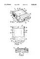
- FIG. 1is a front perspective view of a portable computer apparatus in accordance with one embodiment of the present invention
- FIG. 2is a top view of the apparatus from FIG. 1;
- FIG. 3is a front view of the apparatus from FIG. 1;
- FIG. 4is a left side view of the apparatus from FIG. 1;
- FIG. 5is a right side view of the apparatus of FIG. 1;
- FIG. 6is a bottom view of the apparatus of FIG. 1;
- FIG. 7is a rear view of the apparatus of FIG. 1;
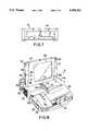
- FIG. 8is a front perspective view of the apparatus of FIG. 1 with the display screen opened into one of its viewing positions;
- FIG. 9is a front perspective view of the apparatus of FIG. 1 showing the contents of a storage compartment therein;
- FIG. 10is a rear view of the apparatus of FIG. 1 showing a power cable compartment therein;
- FIG. 11is a side view of the apparatus of FIG. 1 with the display screen in a first angular viewing position
- FIG. 12is a side view of the apparatus of FIG. 1 with the display screen in a second angular viewing position;
- FIG. 13is a side view of the apparatus of FIG. 1 showing the range of possible viewing positions of the display screen;
- FIGS. 14a, 14b, and 14care side views of the display screen of the apparatus from FIG. 1 in various open viewing positions;
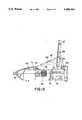
- FIG. 15is an exploded perspective view of the display screen of the apparatus of FIG. 1;
- FIGS. 16a through 16rare illustrations of icons applied to components of the apparatus of FIG. 1.
- FIGS. 1, 8, and 9are front perspective views of apparatus 10.
- FIG. 2is a top view of apparatus 10.
- FIG. 3is a front view
- FIGS. 4, 5, 11, 12, and 13are side views
- FIG. 6is a bottom view
- FIGS. 7 and 10are rear views.
- apparatus 10is a computer device for programing implantable medical devices such as pacemakers, defibrillators, and the like; as such, there are several specialized components incorporated into the apparatus, as will be hereinafter described in greater detail.
- programmer 10includes a processing unit (not shown in the Figures) which in accordance with the presently disclosed embodiment of the invention is a personal computer type motherboard, e.g., a computer motherboard including an Intel 80386 microprocessor and related circuitry such as digital memory.
- a processing unitnot shown in the Figures
- a personal computer type motherboarde.g., a computer motherboard including an Intel 80386 microprocessor and related circuitry such as digital memory.
- the details of design and operation of the computer systemwill not be set forth in detail in the present disclosure, as it is believed that such details are not necessary for an appreciation of the present invention.
- programmer 10is capable of performing at least the types of operations described in the above-referenced Hartlaub et al. programmer patents.
- Programmer 10comprises an outer housing 12, which is preferably made of thermal plastics or another suitably rugged yet relatively light-weight material.
- a carrying handle, designated generally as 14 in the Figures,is integrally formed into the front of housing 12. With handle 14, programmer 10 can be carried like a briefcase.
- an articulating display screen 16is disposed on the upper surface of housing 12. As shall hereinafter be described in greater detail, display screen 16 folds down into a closed position (shown, for example, in FIG. 1), when programmer 10 is not in use, thereby reducing the size of programmer 10 and protecting the display surface of display 16 during transportation and storage thereof.
- Programmer 10has dimensions of approximately 46-cm ⁇ 36-cm ⁇ 13-cm, and weighs approximately 8.4-kg.
- a floppy disk driveis disposed within housing 12 and is accessible via a disk insertion slot designated as 18 in the Figures.
- a hard disk driveis also disposed within housing 12, and it is contemplated that a hard disk drive activity indicator, (e.g., an LED, not shown in the Figures) could be provided to give a visible indication of hard disk activation.
- a hinged expansion slot cover 19is provided on the right side of programmer 10. Cover 19 opens to allow insertion of such an expansion cartridge or the like (not shown).
- a compartment 22 having a hinged cover 24is provided for storing a power cord 26 when programmer 10 is not in use.
- Air vents 32are provided at various points in housing 12, so that an internal fan (not shown) can circulate air within housing 12 and prevent overheating of components therein.
- a printer output slot 34is disposed on the left side of housing 12.
- programmer 10is equipped with an internal strip-chart printer (not shown) so that a hard-copy of a patient's ECG can be generated when the ECG signal is telemetered to the programmer 10 over the above-described telemetry channel.
- ECG printerssuch as the AR-100 printer available from General Scanning Co., are known and commercially available.
- a printer control button 36 and printer speed control buttons 37are disposed on the upper surface of housing 12 so that the printer can be activated and the speed of strip-chart output selected. Buttons 36 and 37 are preferably of the well-known membrane type or are otherwise sealed such that external moisture and dirt are repelled.
- a hinged cover 35can be opened to provide access to the internal printer mechanism, e.g., to supply the printer with paper.
- a power switch 20which is preferably inset slightly with respect to housing 12, such that the likelihood of accidentally turning programmer 10 off is minimized.
- articulating display screen 16is shown with articulating display screen 16 having been lifted up into one of a plurality of possible open positions such that the display area thereof is visible to a user situated in front of programmer 10.
- Articulating display screenis preferably of the LCD or electroluminescent type, characterized by being relatively thin as compared, for example, a cathode ray tube (CRT) or the like.
- CRTcathode ray tube
- display screen 16is one manufactured by and commercially available from Planar Systems, Inc.
- display screen 16is operatively coupled to the computer circuitry disposed within housing 12 and is adapted to provide a visual display of graphics and/or data under control of the internal computer.
- display screen 16is provided with touch-sensitive capability, such that a user can interact with the internal computer by touching the display area of display screen 16 with a stylus, or even the user's finger. It is believed that those of ordinary skill in the computer art will be familiar with touch-sensitive display technology, and the details of implementation of such a display will not be described further herein.
- Touch-sensitive display screen 16is the primary input medium for programmer 10, and therefore preferably has sufficient resolution to support stylus operations including selection, gestures, annotation, and character recognition.
- Compartment 38is used for storage of a programming head 42 which, as would be appreciated by those of ordinary skill in the art, is placed over a patient's body near the implant site of an implanted device, in order to establish a telemetry link between the implanted device and the programmer.
- a programming headis disclosed, for example, in the above-reference Hartlaub programmer patents.
- Programming head 42is coupled to internal circuitry of programmer 10 via a cable 43.
- Compartment 38is also used for storage of a stylus 44 used to interact with touch screen 16.
- Stylus 44is coupled to circuitry within housing 12 via a cable 45 that is coupled to programmer 10 by means of a coaxial connector 46.
- Clips 48are preferably provided on the underside of hinged cover 40 for holding stylus 44 when not in use.
- Compartment 38is also used for storage of a plurality patient cables 50 for obtaining a patient's surface ECG.
- Patient cables 50convey a patient's surface ECG to internal circuitry of programmer 10, so that the surface ECG can be displayed on display screen 16 or printed out on the internal ECG printer, previously described.
- Latching mechanisms 60When display screen 16 is folded into its closed position (see, for example, FIG. 1), it is secured in place by means of latching mechanisms 60 disposed on the left and right sides of housing 12. Latching mechanisms 60 are adapted to be engaged in corresponding recesses 62 disposed on the front surface of display screen 16, and are spring-biased to remain engaged therein until they are simultaneously actuated by pressing inward from the respective right and left sides of programmer 10. To open display screen 16, latching mechanisms 60 are depressed inwardly, thereby becoming disengaged from recesses 62. Latching mechanisms 60 prevent display screen 16 from opening during transportation and storage of programmer 10. Latching mechanisms 60 are further adapted to automatically re-engage recesses 62 when screen 16 is folded down to its closed position, so that no manual actuation of latches 60 is necessary to close screen 16.
- link arms 64are each pivotally secured at one end onto the upper surface of housing 12, at stationary pivot points designated 66.
- link arms 64are each pivotally secured at another end to the respective sides of display screen 16, at the moving pivot points designated 68.
- the dual-pivot articulating configuration of display screen 16 and link arms 64affords a large degree of adjustability of display screen 16, as shall be hereinafter described in further detail.
- a screen support member 70is rigidly disposed on the bottom edge of display screen 16. Display screen 16 rests upon support member 70 when display screen 16 is in any of its possible open positions. When display screen 16 is in the closed position, support member 70 is received in a recess 72 integrally formed into the upper surface of housing 12.
- support member 70When display screen 16 is lifted up into on of its open positions, support member 70 rests at some point within a graduated support channel 74, as shown in FIG. 8.
- Support channel 74extends from substantially proximal to the front of the upper surface of housing 12 towards the back, and in the presently preferred embodiment of the invention is integrally formed into the upper surface of housing 12.
- a plurality of spaced-apart indentations 76are defined in the sides of channel 74. Indentations 76 are provided so that the distal end of support member 70 can be received in channel 74, preventing support member 70 from sliding back and forth therein. Indentations 76 are disposed at points of varying distance from the front of programmer 10. The viewing angle of display screen 16 when in the open position depends upon which of the indentations 76 engage support member 70. Of course, the number of possible viewing angles is determined by the number and spacing of indentations 76 defined in channel 74.
- Viewing angle adjustment of display screen 16is accomplished by lifting screen 16 up slightly so that support member 70 is disengaged from support channel 74. Then, screen 16 can be freely pivoted to a desired position and lowered down such that support member 70 is engaged by a corresponding pair of indentations 76.
- FIG. 11is a side view of programmer 10 with display screen 16 adjusted to the same viewing angle as in FIG. 8.
- FIG. 12is a side view of programmer 10 where support member 70 has been brought forward as compared with FIG. 11, such that display screen 16 is adjusted to a less vertical viewing angle.
- FIG. 13depicts display screen 16 in its two most extreme viewing angles.
- display screen 16is capable of being adjusted from the nearly vertical viewing angle designated 16' in FIG. 13 to the less vertical viewing angle 16" shown in phantom in FIG. 13.
- support member 70is received within a conforming recess 71 formed in the upper surface of housing 12 near the forward end of channel 74.
- indentations 76 in support channel 74are arranged to provide for viewing angles of 19° (the angle designated as 16" in FIG. 13), 36°, 45°, 53°, 60°, 66°, 73°, 81° and 90° (the angle designated as 16' in FIG. 13), ⁇ 1°, from horizontal.
- At least one of the two link arms 64is preferably hollow, such that it can serve as a conduit for wiring necessary to couple display screen 16 to the computer circuitry disposed within housing 12.
- FIGS. 14a, 14b, and 14cthere is shown an illustration of a portion of programmer 10 including one of the link arms 64, display screen 16, and the upper surface of housing 12.
- screen 16is shown in the closed position as in FIG. 1.
- a cable 56is coupled at one end, designated 56' in FIG. 14a, to computer circuitry (not shown) disposed within housing 12. Cable 56 is coupled at another end 56" to display screen 16, such that display screen 16 is capable of displaying graphics and text under control of the internal computer circuitry.
- cable 56extends through hollow link arm 64. With screen 16 in the closed position of FIG. 14a, cable 56 is subjected to a 90° turn at stationary pivot point 44, and to less than a 90° turn at non-stationary pivot point 46.
- FIG. 14bscreen 16 is shown having been lifted up into one of its operational positions, with an approximately 45° viewing angle. It is to be noted that in all of the positions between the closed position of FIG. 5 and the 45° position of FIG. 14b, cable 56 is subjected to turns of less than 90° at stationary pivot point 44. In fact, with the screen in a 90° viewing angle (i.e., when screen 16 is completely vertical), cable 56 is substantially straight as it passes pivot point 44. In the 45° viewing angle of FIG. 14b, cable 56 is subjected to approximately a 90° turn at pivot point 46.
- screen 16is shown having been positioned in its most extreme open position, which is the viewing angle designated as 16" in FIG. 13.
- cable 56is subjected to less than a 90° turn at pivot point 44 and less than a 180° turn at pivot point 46.
- cable 56is subjected to at most a 90° turn at pivot point 44, and at most a 180° turn at pivot point 46.
- This arrangementis believed to be advantageous, as it prevents undue fatigue of cable 56 that could result from subjecting cable 56 to more extreme turns.
- FIG. 15there is shown an exploded perspective view of display screen 16 and link arms 64.
- display screen 16comprises a front housing 80 and a rear housing 82 configured to house a display unit (not shown in FIG. 15), which as previously noted is preferably of the LCD or electroluminescent type.
- Link arms 64are provided with flared projections 88 at each end. Projections 88 are received in an opening in rear housing 82 and pivotally secured therein by means of a securing member 92 adapted to engage flared projection 88 on the end of link arm 64.
- FIGS. 16a through 16ra number of icons and symbols used to identify features of programmer 10 are shown.
- Table 1the meaning of each of the symbols in FIGS. 16a through 16r is set forth:
- FIGS. 16a through 16rare applied at various appropriate locations on programmer 10 so that the features or components to which they refer can be quickly identified and located.
- the icon of FIG. 16nis a solid red square that is applied to an emergency button, designated as 94 in FIG. 8.
- Emergency button 94is prominently located near the front of programmer 10, and it is believed that the solid red color renders button 94 easily identifiable and readily locatable.
- the "deliver stimulating pulse" icon in FIG. 16ois applied to a button, designated 96 in FIG. 8, which when actuated initiates delivery of a stimulating pulse by an implanted device in telemetric communication with programmer 10.
- LED 97functions to provide an indication that programming head 42 is properly positioned above the implant site to allow telemetric communication between programmer 10 and the implanted device.
- LED 97is actually disposed within the front and rear housings (80 and 82) of screen 16 and is visible through a semi-transparent light-tunnel or bezel disposed in an small hole opening in front housing 80.
- the programming head icon of FIG. 16amay be associated with LED 97 to identify this position indicating function of LED 97; in addition, it is contemplated that the bezel itself may be in the shape of the programming head to identify the function of LED 97. It is contemplated that LED 97 may be of the well-known two-color type, in order to distinguish between marginally suitable programming head positioning and more optimal positioning.
- an "ink-well” type indentation 99formed near the lower right-hand comer of display screen 16 to provide a resting place for stylus 44.
Landscapes
- Engineering & Computer Science (AREA)
- Computer Hardware Design (AREA)
- Theoretical Computer Science (AREA)
- Physics & Mathematics (AREA)
- General Engineering & Computer Science (AREA)
- Human Computer Interaction (AREA)
- General Physics & Mathematics (AREA)
- Health & Medical Sciences (AREA)
- Mathematical Physics (AREA)
- Biomedical Technology (AREA)
- Nuclear Medicine, Radiotherapy & Molecular Imaging (AREA)
- Radiology & Medical Imaging (AREA)
- Life Sciences & Earth Sciences (AREA)
- Animal Behavior & Ethology (AREA)
- General Health & Medical Sciences (AREA)
- Public Health (AREA)
- Veterinary Medicine (AREA)
- Measurement And Recording Of Electrical Phenomena And Electrical Characteristics Of The Living Body (AREA)
Abstract
Description
This invention relates to the field of portable computer equipment, and more particularly relates to a portable computer apparatus having an articulating display panel.
Substantial technological improvement in the field of electronics over past years has enabled computer equipment manufacturers to provide powerful, fully-featured computers that are compact and portable. So-called "laptop" or "notebook" type computers have proven to be extremely popular in recent years, and a wide variety of such computers are known and commercially available.
A portable computer apparatus will typically have at least some subset of the following components: a housing for containing the computer circuitry and other electronic components; a power source (e.g., a battery) or at least a cable for connecting the apparatus to a source of power; at least one means for accepting user input (e.g., an alphanumeric keyboard, a "mouse", or the like); and output means (e.g., a text and/or graphic display, a printer, or the like) for communicating information to the user. In addition, portable computer equipment will frequently be equipped with data storage devices, such as a floppy disk drive or a hard disk drive. While some set of these components can be found in any portable computer equipment, there is a nearly endless variety of ways that they can be arranged.
There are a number of design considerations that are of particular concern in the context of portable computer equipment. In general, it is preferable for a portable computer apparatus to be durable and ruggedly constructed, since it should be expected that a portable computer will be picked up, carried about, jostled, and even dropped occasionally. Moreover, while the size and weight of portable computer equipment is preferably kept to a minimum, this is preferably not achieved at the expense of making components like the display, keyboard, or battery too small, or at the expense of making structural components weak and easily broken.
Ergonomic factors should also be considered in the design of portable computer equipment. For example, some portable computers, such as the Compaq SLT, are provided with detachable keyboards so that a user can position the keyboard conveniently for typing without having to move the entire computer. Also, portable computers often are equipped with a display screen that can be manipulated into a variety of orientations so that it can be easily viewed by the user from different angles. This is particularly important with liquid-crystal displays (LCDs), which are typically more difficult to view at oblique angles.
One common way in which portable computer manufacturers satisfy the requirements of portability, ruggedness, and ergonomic convenience is by providing a hinged display screen that can be folded down and secured onto the top of the computer housing, thereby protecting the screen and reducing the size of the apparatus when not in use. When opened, the hinged display screen can be adjusted over a range of viewing angles so that the user can select a convenient one. As a further expedient, the closed hinged display can serve as a protective structure for other components, such as the keyboard. Such a configuration is described in U.S. Pat. No. 4,903,222 to Carter et al. entitled "Arrangement of Components in a Laptop Computer System", which patent is incorporated herein by reference in its entirety.
A portable computer having an hinged display screen which folds down over an alphanumeric keyboard is also disclosed in U.S. Pat. No. 5,090,913 to Kobayashi; in U.S. Pat. No. 5,016,849 to Wu; in U.S. Pat. No. 5,052,078 to Hosoi; in U.S. Pat. No. 4,976,007 to Lam; and in U.S. Pat. No. 4,960,256 to Chihara et al.
In addition to the various types of general-purpose portable computer equipment that are known and commercially available, there are also many different types of special-purpose, portable computer devices. Such devices may have many of the same components found in general-purpose computers, but may also have additional components, depending upon the specialized purpose for which they are intended. The class of special-purpose portable computer equipment may include such devices as service or test equipment carried by field service technicians; data storage and acquisition carried by delivery persons, meter-readers and the like; portable communications devices; and of particular relevance to the present invention, computerized programmers for implantable medical devices and the like.
Implantable medical devices, such as cardiac pacemakers, cardiac defibrillators, neural stimulators, and the like, are often programmable in their operation by means of a radio-frequency telemetry link established between the device and an external programmer unit. In the case of cardiac pacemakers, for example, a clinician may, through the use of an external programmer, control such parameters as pacing rate, pacing mode, sensitivity, pacing output, and the like, in a pacemaker implanted in a patient. Pacemaker programmers are preferably portable, so that they may be conveniently transported from patient to patient in a hospital, or even taken to a patient's home or to another non-hospital setting. Portability is also desirable due to the possibility that the programmer may be needed in an emergency situation, e.g., when the patient is undergoing surgery in an operating room. A variety of different programmable pacemakers, and external programming units therefor, are known and commercially available.
A programmer for non-invasively programming a cardiac pacemaker is described in its various aspects in the following U.S. Patents to Hartlaub et al., each commonly assigned to the assignee of the present invention and each incorporated by reference herein: U.S. Pat. No. 4,250,884 entitled "Apparatus For and Method Of Programming the Minimum Energy Threshold for Pacing Pulses to be Applied to a Patient's Heart"; U.S. Pat. No. 4,273,132 entitled "Digital Cardiac Pacemaker with Threshold Margin Check"; U.S. Pat. No. 4,273,133 entitled Programmable Digital Cardiac Pacemaker with Means to Override Effects of Reed Switch Closure"; U.S. Pat. No. 4,233,985 entitled "Multi-Mode Programmable Digital Cardiac Pacemaker"; and U.S. Pat. No. 4,253,466 entitled "Temporary and Permanent Programmable Digital Cardiac Pacemaker".
Aspects of the programmer that is the subject of the foregoing Hartlaub et al. patents (hereinafter "the Hartlaub programmer") are also described in U.S. Pat. No. 4,208,008 to Smith, entitled "Pacing Generator Programming Apparatus Including Error Detection Means" and in U.S. Pat. No. 4,236,524 to Powell et al., entitled "Program Testing Apparatus". The Smith '008 and Powell et al. '524 patents are also incorporated by reference herein in their entirety.
A telemetry system for communicating information, either in analog or digital form, between an implanted device and an external programming apparatus is disclosed in U.S. Pat. No. 4,374,382 to Markowitz entitled "Marker Channel Telemetry System for a Medical Device", and in U.S. Pat. No. 4,556,063 to Thompson et al., entitled "Telemetry System for a Medical Device". The Markowitz '382 and Thompson et al. '063 patents are commonly assigned to the assignee of the present invention and are both hereby incorporated by reference in their entirety.
Implanted devices in general have improved in their sophistication and functionality over the past years, and it has become increasingly more important for a physician or clinician to be able to interrogate the device to determine its operational status, and to be able to communicate numerous commands and parameters to the device in order to control various aspects of the device's operation. Improvements in the telemetry system, as reflected, for example, in the above-reference Thompson '063 patent, have enabled a great deal of information to be readily and quickly exchanged between the implanted device and the external programming unit. In some cases, a real-time electrocardiogram (ECG) signal may be transmitted from the implanted device to an external unit, so that the physician can monitor the patient's heart activity and the effects of pacing pulses thereon. A pacemaker system having such capability is described, for example, in U.S. Pat. No. Re. 32,361 to Duggan, entitled "Implantable Telemetry Transmission System for Analog and Digital Data", assigned to the assignee of the present invention and incorporated into the present disclosure by reference in its entirety.
Given the level of sophistication and functionality of state-of-the-art pacemakers, it has become necessary for the operational capability of external programming units for such pacemakers to be similarly improved. For example, since pacemakers are known which are capable of transmitting real-time ECG signals to an external unit, it would naturally be desirable for the external unit to be able to visually display the ECG signal, without the need for additional wiring or equipment.
In addition to the above-discussed considerations that should be taken into account in designing a portable, general-purpose computer, there are certain factors that are of particular importance in the context of medical device programming units. A medical device programming unit should be simple to operate, highly reliable, and well adapted for use in an operating room or other clinical setting.
The present invention relates to a portable computer apparatus, and in particular relates to a portable, computer-based external programming unit for implantable medical devices.
In accordance with one embodiment of the invention, a portable computer apparatus is provided which has a dual-pivot articulating display screen which can be readily adjusted into a plurality of viewing angles, and which folds down to a closed, latched position on top of the computer apparatus when the apparatus is not being used or is being transported.
In the preferred embodiment, the apparatus is especially designed to function as a programming unit for implantable medical devices, such as pacemakers, defibrillators, and the like. As such, it is equipped with an internal ECG strip-chart printer, as well as a magnetic programming head used in establishing a telemetry link with implanted devices.
In accordance with the present invention, the disclosed computer apparatus is further provided with a touch-sensitive screen actuable by means of a stylus. The touch-sensitive screen serves as the principal means of user interaction with the apparatus, so that the need for a separate keyboard or other user-input means is generally obviated.
The foregoing and other aspects of the present invention will be best appreciated with reference to the detailed description of a specific embodiment of the invention, which follows, when read in conjunction with the accompanying drawings, wherein:
FIG. 1 is a front perspective view of a portable computer apparatus in accordance with one embodiment of the present invention;
FIG. 2 is a top view of the apparatus from FIG. 1;
FIG. 3 is a front view of the apparatus from FIG. 1;
FIG. 4 is a left side view of the apparatus from FIG. 1;
FIG. 5 is a right side view of the apparatus of FIG. 1;
FIG. 6 is a bottom view of the apparatus of FIG. 1;
FIG. 7 is a rear view of the apparatus of FIG. 1;
FIG. 8 is a front perspective view of the apparatus of FIG. 1 with the display screen opened into one of its viewing positions;
FIG. 9 is a front perspective view of the apparatus of FIG. 1 showing the contents of a storage compartment therein;
FIG. 10 is a rear view of the apparatus of FIG. 1 showing a power cable compartment therein;
FIG. 11 is a side view of the apparatus of FIG. 1 with the display screen in a first angular viewing position;
FIG. 12 is a side view of the apparatus of FIG. 1 with the display screen in a second angular viewing position;
FIG. 13 is a side view of the apparatus of FIG. 1 showing the range of possible viewing positions of the display screen; FIGS. 14a, 14b, and 14c are side views of the display screen of the apparatus from FIG. 1 in various open viewing positions;
FIG. 15 is an exploded perspective view of the display screen of the apparatus of FIG. 1; and
FIGS. 16a through 16r are illustrations of icons applied to components of the apparatus of FIG. 1.
A presently preferred embodiment of the invention is illustrated from various perspectives in FIGS. 1 through 13, in order that various features of the invention can be shown. FIGS. 1, 8, and 9 are front perspective views ofapparatus 10. FIG. 2 is a top view ofapparatus 10. FIG. 3 is a front view, FIGS. 4, 5, 11, 12, and 13 are side views, FIG. 6 is a bottom view, and FIGS. 7 and 10 are rear views.
In the presently preferred embodiment of the invention,apparatus 10 is a computer device for programing implantable medical devices such as pacemakers, defibrillators, and the like; as such, there are several specialized components incorporated into the apparatus, as will be hereinafter described in greater detail. Internally,programmer 10 includes a processing unit (not shown in the Figures) which in accordance with the presently disclosed embodiment of the invention is a personal computer type motherboard, e.g., a computer motherboard including an Intel 80386 microprocessor and related circuitry such as digital memory. The details of design and operation of the computer system will not be set forth in detail in the present disclosure, as it is believed that such details are not necessary for an appreciation of the present invention. For the purposes of the present disclosure, it suffices to state thatprogrammer 10 is capable of performing at least the types of operations described in the above-referenced Hartlaub et al. programmer patents.
In accordance with one aspect of the present invention, an articulatingdisplay screen 16 is disposed on the upper surface ofhousing 12. As shall hereinafter be described in greater detail,display screen 16 folds down into a closed position (shown, for example, in FIG. 1), whenprogrammer 10 is not in use, thereby reducing the size ofprogrammer 10 and protecting the display surface ofdisplay 16 during transportation and storage thereof.
Referring to FIG. 5, a floppy disk drive is disposed withinhousing 12 and is accessible via a disk insertion slot designated as 18 in the Figures. A hard disk drive is also disposed withinhousing 12, and it is contemplated that a hard disk drive activity indicator, (e.g., an LED, not shown in the Figures) could be provided to give a visible indication of hard disk activation.
As would be appreciated by those of ordinary skill in the art, it is often desirable to provide a means forprogrammer 10 to adapt its mode of operation depending upon the type of implanted device to be programmed. Accordingly, it may be desirable to have an expansion cartridge containing EPROMs or the like for storing program information to controlprogrammer 10 to operate in a particular manner corresponding to a given type of implantable device. As shown in FIG. 5, a hingedexpansion slot cover 19 is provided on the right side ofprogrammer 10.Cover 19 opens to allow insertion of such an expansion cartridge or the like (not shown).
Referring to FIG. 10, acompartment 22 having a hingedcover 24 is provided for storing apower cord 26 whenprogrammer 10 is not in use.
Air vents 32 (shown in FIGS. 1, 3, 4, 5, and 8, for example) are provided at various points inhousing 12, so that an internal fan (not shown) can circulate air withinhousing 12 and prevent overheating of components therein. In addition, a printer output slot 34 (see FIGS. 1 and 4, for example) is disposed on the left side ofhousing 12. In accordance with the presently preferred embodiment of the invention,programmer 10 is equipped with an internal strip-chart printer (not shown) so that a hard-copy of a patient's ECG can be generated when the ECG signal is telemetered to theprogrammer 10 over the above-described telemetry channel. Several types of ECG printers, such as the AR-100 printer available from General Scanning Co., are known and commercially available. Aprinter control button 36 and printerspeed control buttons 37 are disposed on the upper surface ofhousing 12 so that the printer can be activated and the speed of strip-chart output selected.Buttons
A hingedcover 35 can be opened to provide access to the internal printer mechanism, e.g., to supply the printer with paper. Also shown in FIGS. 1 and 4 is apower switch 20 which is preferably inset slightly with respect tohousing 12, such that the likelihood of accidentally turningprogrammer 10 off is minimized.
In the perspective view of FIG. 8,programmer 10 is shown with articulatingdisplay screen 16 having been lifted up into one of a plurality of possible open positions such that the display area thereof is visible to a user situated in front ofprogrammer 10. Articulating display screen is preferably of the LCD or electroluminescent type, characterized by being relatively thin as compared, for example, a cathode ray tube (CRT) or the like. In the presently preferred embodiment of the invention,display screen 16 is one manufactured by and commercially available from Planar Systems, Inc.
As would be appreciated by those of ordinary skill in the computer art,display screen 16 is operatively coupled to the computer circuitry disposed withinhousing 12 and is adapted to provide a visual display of graphics and/or data under control of the internal computer.
In accordance with one aspect of the present invention,display screen 16 is provided with touch-sensitive capability, such that a user can interact with the internal computer by touching the display area ofdisplay screen 16 with a stylus, or even the user's finger. It is believed that those of ordinary skill in the computer art will be familiar with touch-sensitive display technology, and the details of implementation of such a display will not be described further herein. Touch-sensitive display screen 16 is the primary input medium forprogrammer 10, and therefore preferably has sufficient resolution to support stylus operations including selection, gestures, annotation, and character recognition.
Referring to FIG. 9, acompartment 38 with a hingedcover 40 is provided generally near the front ofprogrammer 10.Compartment 38 is used for storage of aprogramming head 42 which, as would be appreciated by those of ordinary skill in the art, is placed over a patient's body near the implant site of an implanted device, in order to establish a telemetry link between the implanted device and the programmer. Such a programming head is disclosed, for example, in the above-reference Hartlaub programmer patents.Programming head 42 is coupled to internal circuitry ofprogrammer 10 via acable 43.
Whendisplay screen 16 is folded into its closed position (see, for example, FIG. 1), it is secured in place by means of latchingmechanisms 60 disposed on the left and right sides ofhousing 12. Latchingmechanisms 60 are adapted to be engaged incorresponding recesses 62 disposed on the front surface ofdisplay screen 16, and are spring-biased to remain engaged therein until they are simultaneously actuated by pressing inward from the respective right and left sides ofprogrammer 10. Toopen display screen 16, latchingmechanisms 60 are depressed inwardly, thereby becoming disengaged fromrecesses 62. Latchingmechanisms 60 preventdisplay screen 16 from opening during transportation and storage ofprogrammer 10. Latchingmechanisms 60 are further adapted to automatically re-engagerecesses 62 whenscreen 16 is folded down to its closed position, so that no manual actuation oflatches 60 is necessary to closescreen 16.
Referring to FIGS. 1 and 8, it can be seen thatdisplay screen 16 is supported by left andright link arms 64.Link arms 64 are each pivotally secured at one end onto the upper surface ofhousing 12, at stationary pivot points designated 66. In addition, and in accordance with another aspect of the present invention, linkarms 64 are each pivotally secured at another end to the respective sides ofdisplay screen 16, at the moving pivot points designated 68. The dual-pivot articulating configuration ofdisplay screen 16 and linkarms 64 affords a large degree of adjustability ofdisplay screen 16, as shall be hereinafter described in further detail.
Ascreen support member 70 is rigidly disposed on the bottom edge ofdisplay screen 16.Display screen 16 rests uponsupport member 70 whendisplay screen 16 is in any of its possible open positions. Whendisplay screen 16 is in the closed position,support member 70 is received in arecess 72 integrally formed into the upper surface ofhousing 12.
Whendisplay screen 16 is lifted up into on of its open positions,support member 70 rests at some point within a graduatedsupport channel 74, as shown in FIG. 8.Support channel 74 extends from substantially proximal to the front of the upper surface ofhousing 12 towards the back, and in the presently preferred embodiment of the invention is integrally formed into the upper surface ofhousing 12. A plurality of spaced-apartindentations 76 are defined in the sides ofchannel 74.Indentations 76 are provided so that the distal end ofsupport member 70 can be received inchannel 74, preventingsupport member 70 from sliding back and forth therein.Indentations 76 are disposed at points of varying distance from the front ofprogrammer 10. The viewing angle ofdisplay screen 16 when in the open position depends upon which of theindentations 76 engagesupport member 70. Of course, the number of possible viewing angles is determined by the number and spacing ofindentations 76 defined inchannel 74.
Viewing angle adjustment ofdisplay screen 16 is accomplished by liftingscreen 16 up slightly so thatsupport member 70 is disengaged fromsupport channel 74. Then,screen 16 can be freely pivoted to a desired position and lowered down such thatsupport member 70 is engaged by a corresponding pair ofindentations 76.
FIG. 11 is a side view ofprogrammer 10 withdisplay screen 16 adjusted to the same viewing angle as in FIG. 8. FIG. 12 is a side view ofprogrammer 10 wheresupport member 70 has been brought forward as compared with FIG. 11, such thatdisplay screen 16 is adjusted to a less vertical viewing angle.
FIG. 13 depictsdisplay screen 16 in its two most extreme viewing angles. In particular,display screen 16 is capable of being adjusted from the nearly vertical viewing angle designated 16' in FIG. 13 to the lessvertical viewing angle 16" shown in phantom in FIG. 13. In the viewing angle designated as 16" in FIG. 13,support member 70 is received within a conformingrecess 71 formed in the upper surface ofhousing 12 near the forward end ofchannel 74. It is to be understood, of course, that a plurality of viewing angles between the two extremes depicted in FIG. 13 are also available. In the presently preferred embodiment of the invention,indentations 76 insupport channel 74 are arranged to provide for viewing angles of 19° (the angle designated as 16" in FIG. 13), 36°, 45°, 53°, 60°, 66°, 73°, 81° and 90° (the angle designated as 16' in FIG. 13), ±1°, from horizontal.
At least one of the twolink arms 64 is preferably hollow, such that it can serve as a conduit for wiring necessary to coupledisplay screen 16 to the computer circuitry disposed withinhousing 12. Referring to FIGS. 14a, 14b, and 14c, there is shown an illustration of a portion ofprogrammer 10 including one of thelink arms 64,display screen 16, and the upper surface ofhousing 12. In FIG. 14a,screen 16 is shown in the closed position as in FIG. 1. Acable 56 is coupled at one end, designated 56' in FIG. 14a, to computer circuitry (not shown) disposed withinhousing 12.Cable 56 is coupled at anotherend 56" to displayscreen 16, such thatdisplay screen 16 is capable of displaying graphics and text under control of the internal computer circuitry. As shown in FIG. 14a,cable 56 extends throughhollow link arm 64. Withscreen 16 in the closed position of FIG. 14a,cable 56 is subjected to a 90° turn atstationary pivot point 44, and to less than a 90° turn atnon-stationary pivot point 46.
In FIG. 14b,screen 16 is shown having been lifted up into one of its operational positions, with an approximately 45° viewing angle. It is to be noted that in all of the positions between the closed position of FIG. 5 and the 45° position of FIG. 14b,cable 56 is subjected to turns of less than 90° atstationary pivot point 44. In fact, with the screen in a 90° viewing angle (i.e., whenscreen 16 is completely vertical),cable 56 is substantially straight as it passespivot point 44. In the 45° viewing angle of FIG. 14b,cable 56 is subjected to approximately a 90° turn atpivot point 46.
In FIG. 14c,screen 16 is shown having been positioned in its most extreme open position, which is the viewing angle designated as 16" in FIG. 13. In the viewing position of FIG. 14c,cable 56 is subjected to less than a 90° turn atpivot point 44 and less than a 180° turn atpivot point 46.
Thus,cable 56 is subjected to at most a 90° turn atpivot point 44, and at most a 180° turn atpivot point 46. This arrangement is believed to be advantageous, as it prevents undue fatigue ofcable 56 that could result from subjectingcable 56 to more extreme turns.
In FIG. 15, there is shown an exploded perspective view ofdisplay screen 16 and linkarms 64. As shown in FIG. 15,display screen 16 comprises afront housing 80 and arear housing 82 configured to house a display unit (not shown in FIG. 15), which as previously noted is preferably of the LCD or electroluminescent type.Link arms 64 are provided with flaredprojections 88 at each end.Projections 88 are received in an opening inrear housing 82 and pivotally secured therein by means of a securingmember 92 adapted to engage flaredprojection 88 on the end oflink arm 64.
As previously discussed, there are certain overall design considerations that are particularly relevant in the context of implantable device programming apparatuses. During implantable device programming, it is important that the operator be able to concentrate on the patient and the patient's well-being, rather than being distracted with the details of programmer operation. In order to ensure that operation ofprogrammer 10 is intuitive and efficient, several components ofprogrammer 10 are identified by simple pictorial representations or icons with readily apparent meaning. It is believed that the use of symbols in this manner is well known in the art. See, for example, U.S. Pat. Des. No. 295,631 to Wells-Papanek et al. entitled "Icon for Dividers or the Like"; and U.S. Pat. Des. No. 295,632 to Wells-Papanek et al. entitled "Icon for Wastebasket or the Like".
Referring to FIGS. 16a through 16r, a number of icons and symbols used to identify features ofprogrammer 10 are shown. In the following Table 1, the meaning of each of the symbols in FIGS. 16a through 16r is set forth:
______________________________________ FIG. Meaning ______________________________________ 16a programming head 16b calibrate 16c analog output 16d keyboard output 16e AC cable location 16f electrocardiogram (ECG) 16g printer 16h 25-mm/sec paper speed 16i 12.5-mm/sec paper speed 16j paper advance 16k interrogate / program 16l stylus connector 16m warning -- see reference manual for information 16n emergency switch 16o deliver stimulating pulse 16p serial data port 16q parallel data port 16r VGA graphics port ______________________________________
The icons of FIGS. 16a through 16r are applied at various appropriate locations onprogrammer 10 so that the features or components to which they refer can be quickly identified and located. For example, the icon of FIG. 16n is a solid red square that is applied to an emergency button, designated as 94 in FIG. 8.Emergency button 94 is prominently located near the front ofprogrammer 10, and it is believed that the solid red color rendersbutton 94 easily identifiable and readily locatable. Whenemergency button 94 is pressed,programmer 10 enters into an emergency mode of operation, a mode commonly provided for in prior art programmers. Similarly, the "deliver stimulating pulse" icon in FIG. 16o is applied to a button, designated 96 in FIG. 8, which when actuated initiates delivery of a stimulating pulse by an implanted device in telemetric communication withprogrammer 10.
Referring to FIGS. 8 and 9, anLED 97 or similar visual indicator is visible near the upper left-hand corner ofdisplay screen 16.LED 97 functions to provide an indication thatprogramming head 42 is properly positioned above the implant site to allow telemetric communication betweenprogrammer 10 and the implanted device. In one embodiment of the invention,LED 97 is actually disposed within the front and rear housings (80 and 82) ofscreen 16 and is visible through a semi-transparent light-tunnel or bezel disposed in an small hole opening infront housing 80. The programming head icon of FIG. 16a may be associated withLED 97 to identify this position indicating function ofLED 97; in addition, it is contemplated that the bezel itself may be in the shape of the programming head to identify the function ofLED 97. It is contemplated thatLED 97 may be of the well-known two-color type, in order to distinguish between marginally suitable programming head positioning and more optimal positioning.
Also with reference to FIGS. 8 and 9, an "ink-well"type indentation 99 formed near the lower right-hand comer ofdisplay screen 16 to provide a resting place forstylus 44.
From the foregoing detailed description of a specific embodiment of the invention, it should be apparent that a portable computer apparatus having an articulating display screen adjustable to a plurality of viewing angles has been disclosed. Although a specific embodiment of the invention has been disclosed in some detail, it is to be understood that this has been done for the purposes of illustration only, and is not intended to limit the scope of the present invention as defined in the accompanying claims. It is contemplated that various alterations, substitutions, and modifications can be made to the embodiment of the invention described herein without departing from the spirit and scope of the invention as defined in the claims. For example, although the present invention has been described herein in the context of a programming apparatus for use in conjunction with implanted medical devices and the like, it is believed that the present invention may be equally advantageously practiced in conjunction with many other types of portable computer equipment.
Claims (8)
1. A portable computer apparatus, comprising:
a main housing having an upper surface and containing computer circuitry;
a display screen having side edges and upper and lower edges;
a link arm coupled between said main housing and said display screen, said link arm pivotally coupled at one end thereof to said main housing and pivotally coupled at a second end thereof to said display screen, at a location spaced from said lower edge to enable said screen assembly to articulate relative to said housing;
an engagement mechanism disposed between said display screen and said housing cooperating to stably maintain said screen at any of a plurality of viewing angles, said housing provided with a support channel located centrally on said upper surface of said housing, said engagement mechanism comprising a support member extending from a central location on said lower edge of said display screen, engageable with said support channel.
2. An apparatus in accordance with claim 1, wherein said link arm is coupled to said display screen along a side edge thereof.
3. An apparatus in accordance with claim 1, wherein said support channel defines a plurality of detents therein for engaging said support member.
4. An apparatus in accordance with claim 1, wherein said engagement mechanism comprises a support member adapted to be frictionally engaged in said support channel.
5. A portable computer apparatus, comprising:
a main housing, having an upper surface, said main housing containing
computer circuitry;
a display screen having a substantially flat display surface and having top, bottom, left and right edges;
left and right link arms coupled between said main housing and said display screen, said left link arm pivotally coupled at one end thereof to said main housing upper surface and pivotally coupled at a second end thereof to said left side of said display screen, said right link arm pivotally coupled at one end thereof to said main housing upper surface and at a second end thereof to said right side of said display screen;
a support member, extending from a central portion of said bottom edge of said display screen;
a support channel disposed on a central portion of said main housing upper surface, extending from a forward location to a rear location thereon, said support channel adapted to engage said support member at a plurality of locations therein;
said display screen movable from a closed position wherein said display surface faces and is substantially parallel to said main housing upper surface, to any of a plurality of different viewing angles, said support member being engaged at a different location in said support channel for each of said different viewing angles.
6. The apparatus of claim 5, further comprising:
left and right latch mechanisms, disposed on said main housing upper surface and adapted to secure said display screen in said closed position.
7. The apparatus of claim 5, further comprising:
a carrying handle, disposed on a forward end of said apparatus;
a storage compartment having a hinged cover which defines a portion of said upper surface;
a power cable compartment having a hinged cover, disposed on a rear end of said apparatus.
8. The apparatus of claim 5, wherein at least one of said link arms is hollow, and wherein a wire for conducting an electrical signal from said computer circuitry to said display screen passes through said at least one hollow link arm.
Priority Applications (1)
| Application Number | Priority Date | Filing Date | Title |
|---|---|---|---|
| US08/055,072US5345362A (en) | 1993-04-29 | 1993-04-29 | Portable computer apparatus with articulating display panel |
Applications Claiming Priority (1)
| Application Number | Priority Date | Filing Date | Title |
|---|---|---|---|
| US08/055,072US5345362A (en) | 1993-04-29 | 1993-04-29 | Portable computer apparatus with articulating display panel |
Publications (1)
| Publication Number | Publication Date |
|---|---|
| US5345362Atrue US5345362A (en) | 1994-09-06 |
Family
ID=21995399
Family Applications (1)
| Application Number | Title | Priority Date | Filing Date |
|---|---|---|---|
| US08/055,072Expired - LifetimeUS5345362A (en) | 1993-04-29 | 1993-04-29 | Portable computer apparatus with articulating display panel |
Country Status (1)
| Country | Link |
|---|---|
| US (1) | US5345362A (en) |
Cited By (195)
| Publication number | Priority date | Publication date | Assignee | Title |
|---|---|---|---|---|
| USD358583S (en) | 1993-04-29 | 1995-05-23 | Medtronic, Inc. | Portable computer with an articulating display panel |
| US5527348A (en)* | 1995-02-03 | 1996-06-18 | Medtronic, Inc. | Magnetically permeable E-shield and method of connection thereto |
| US5549654A (en)* | 1994-04-15 | 1996-08-27 | Medtronic, Inc. | Interactive interpretation of event markers in body-implantable medical device |
| FR2739470A1 (en)* | 1995-09-29 | 1997-04-04 | Pettmann Marc | Data processing console for medical electrical pulse stimulation |
| US5694289A (en)* | 1994-08-10 | 1997-12-02 | Ricoh Company, Ltd. | Information processing apparatus with operation panel which is changeable in direction of operation |
| US5693076A (en)* | 1996-01-16 | 1997-12-02 | Medtronic, Inc. | Compressed patient narrative storage in and full text reconstruction from implantable medical devices |
| WO1998029160A1 (en) | 1996-12-26 | 1998-07-09 | Medtronic, Inc. | Method and apparatus for controlling an implanted medical device in a time-dependent manner |
| US5842672A (en)* | 1996-06-07 | 1998-12-01 | Ergotron, Inc. | Mounting system for flat panel display, keyboard and stand |
| US5870280A (en)* | 1997-06-25 | 1999-02-09 | Compal Electronics, Inc. | Base for liquid crystal display having receptacle for accessories |
| US5869919A (en)* | 1994-06-09 | 1999-02-09 | Canon Kabushiki Kaisha | Air cooling for flat panel displays |
| US5871508A (en)* | 1997-08-06 | 1999-02-16 | Medtronic, Inc. | Apparatus for cardiac pacing in transplant |
| US5900848A (en)* | 1996-05-17 | 1999-05-04 | Sharp Kabushiki Kaisha | Information processing apparatus |
| US5899421A (en)* | 1996-03-15 | 1999-05-04 | Fujitsu Limited | Stand for a portable computer |
| US5915661A (en)* | 1997-08-01 | 1999-06-29 | Fujitsu Limited | Collapsible desk stand for portable computer |
| EP0927922A1 (en)* | 1998-01-05 | 1999-07-07 | Siemens Aktiengesellschaft | Apparatus comprising a computer and an integrated telecommunication device |
| US5926364A (en)* | 1997-05-30 | 1999-07-20 | International Business Machines Corporation | Tri-fold personal computer with touchpad and keyboard |
| WO1999037361A1 (en)* | 1998-01-23 | 1999-07-29 | Intermedics Inc. | Training unit for the pacemaker emergency intervention system |
| US5944745A (en)* | 1996-09-25 | 1999-08-31 | Medtronic, Inc. | Implantable medical device capable of prioritizing diagnostic data and allocating memory for same |
| US6006243A (en)* | 1997-05-30 | 1999-12-21 | International Business Machines Corporation | Foldable personal computer with detachable cover section |
| FR2780224A1 (en) | 1998-06-19 | 1999-12-24 | Medtronic Inc | Communication system for linking medical implant circuit to external control |
| US6044473A (en)* | 1997-03-25 | 2000-03-28 | Samsung Electronics Co., Ltd. | Portable computer having a switch for changing a power-controlling mode |
| WO2000034848A1 (en)* | 1998-12-11 | 2000-06-15 | Inclose Design, Inc. | Computer system having thin-profile display with removeable connector assembly |
| US6125028A (en)* | 1996-04-25 | 2000-09-26 | Canon Kabushiki Kaisha | Information processing system |
| US6144549A (en)* | 1998-03-12 | 2000-11-07 | Dell Usa, L.P. | Peripheral bay flat panel display module for computer |
| US6151012A (en)* | 1995-11-16 | 2000-11-21 | Bullister; Edward | Multifunctional portable computing device with special housing |
| US6161039A (en)* | 1998-05-07 | 2000-12-12 | Medtronic, Inc. | Trigger enhanced electrogram display for positioning an implantable medical device |
| US6175488B1 (en)* | 1997-05-07 | 2001-01-16 | Kabushiki Kaisha Toshiba | Electronic apparatus with cover for covering detachable functional component |
| US6219230B1 (en) | 1998-12-01 | 2001-04-17 | Samsung Electronics Co., Ltd. | Portable computer with improved assembly design |
| US6233138B1 (en)* | 1999-07-16 | 2001-05-15 | Evergreen Innovations, L.L.C. | Telescoping pivot hinge for computer display |
| US6262569B1 (en)* | 1994-11-30 | 2001-07-17 | Utility Test Equipment Company | Computerized solid state energy meter test system and method of testing |
| US6266566B1 (en) | 1999-05-21 | 2001-07-24 | Medtronic, Inc. | Waveform normalization in a medical device |
| US6266555B1 (en) | 1998-05-07 | 2001-07-24 | Medtronic, Inc. | Single complex electrogram display having a sensing threshold for an implantable medical device |
| WO2001056467A1 (en) | 2000-02-04 | 2001-08-09 | Medtronic, Inc. | Information remote monitor (irm) medical device |
| US6275376B1 (en) | 1998-10-16 | 2001-08-14 | Samsung Electronics Co., Ltd. | Portable computer display tilt/swivel mechanism and method |
| WO2001087413A1 (en)* | 2000-04-25 | 2001-11-22 | Medtronic, Inc. | Interface devices for instruments in communication with implantable medical devices |
| WO2002001387A2 (en) | 2000-06-23 | 2002-01-03 | Medtronic, Inc. | Human language translation of patient session information from implantable medical devices |
| US6363282B1 (en) | 1999-10-29 | 2002-03-26 | Medtronic, Inc. | Apparatus and method to automatic remote software updates of medical device systems |
| US20020045920A1 (en)* | 2000-08-26 | 2002-04-18 | Medtronic, Inc. | Implanted medical device telemetry using integrated thin film bulk acoustic resonator filtering |
| US6381128B1 (en) | 2000-07-17 | 2002-04-30 | Russel G. Kramer | Ergonomic portable computer |
| US6392657B1 (en)* | 1998-11-13 | 2002-05-21 | E-Color, Inc. | Method and apparatus for characterizing an optimal viewing angle of flat display |
| US20020072785A1 (en)* | 1999-12-14 | 2002-06-13 | Medtronic, Inc. | Apparatus and method for remote therapy and diagnosis in medical devices via interface systems |
| WO2002047761A2 (en) | 2000-12-14 | 2002-06-20 | Medtronic, Inc. | Atrial aware vvi: a method for atrial synchronous ventricular (vdd/r) pacing using the subcutaneous electrode array and a standard pacing lead |
| US6411851B1 (en)* | 1999-11-04 | 2002-06-25 | Medtronic, Inc. | Implantable medical device programming apparatus having an auxiliary component storage compartment |
| US6430038B1 (en) | 2000-04-18 | 2002-08-06 | Hewlett-Packard Company | Computer with articulated mechanism |
| US6437973B1 (en) | 2000-04-18 | 2002-08-20 | Hewlett-Packard Company | Modular mechanism for movable display |
| US6442433B1 (en) | 1999-10-26 | 2002-08-27 | Medtronic, Inc. | Apparatus and method for remote troubleshooting, maintenance and upgrade of implantable device systems |
| US6453195B1 (en) | 2001-03-19 | 2002-09-17 | Medtronic, Inc. | Closed loop drug delivery system and remote management thereof |
| US6463329B1 (en) | 2000-08-01 | 2002-10-08 | Medtronic, Inc. | Null-free antenna array for use in communication with implantable medical devices |
| US6462941B1 (en)* | 2000-06-30 | 2002-10-08 | Palm, Inc. | Method and apparatus for backlighting a handwriting input area for a portable computing device |
| WO2002047546A3 (en)* | 2000-12-13 | 2002-10-17 | Medtronic Inc | Thin electrodes for sensing cardiac depolarization signals |
| US6469802B1 (en)* | 1998-02-06 | 2002-10-22 | Matsushita Electric Industrial Co., Ltd. | Tilt adjusting mechanism for display |
| US6480374B1 (en)* | 2000-11-14 | 2002-11-12 | Inventec Appliances Corp. | Vertically disposed notebook computer |
| US20020180692A1 (en)* | 2001-05-31 | 2002-12-05 | Rhoads Monte J. | Rack mount server with tiltable display |
| US6496715B1 (en) | 1996-07-11 | 2002-12-17 | Medtronic, Inc. | System and method for non-invasive determination of optimal orientation of an implantable sensing device |
| US6505067B1 (en) | 2000-11-22 | 2003-01-07 | Medtronic, Inc. | System and method for deriving a virtual ECG or EGM signal |
| US6504707B2 (en)* | 2000-06-14 | 2003-01-07 | International Business Machines Corporation | Portable computer |
| US6512940B1 (en) | 2000-10-31 | 2003-01-28 | Medtronic, Inc. | Subcutaneous spiral electrode for sensing electrical signals of the heart |
| US6522915B1 (en) | 2000-10-26 | 2003-02-18 | Medtronic, Inc. | Surround shroud connector and electrode housings for a subcutaneous electrode array and leadless ECGS |
| US20030041866A1 (en)* | 1999-12-17 | 2003-03-06 | Medtronic, Inc. | Virtual remote monitor, alert, diagnostics and programming for implantable medical device systems |
| US6532147B1 (en) | 1999-09-24 | 2003-03-11 | International Business Machines Corporation | Flexible monitor/display on mobile device |
| US20030061123A1 (en)* | 2000-02-04 | 2003-03-27 | Mcmenimen James L. | Responsive manufacturing and inventory control |
| US20030078627A1 (en)* | 2000-12-21 | 2003-04-24 | Medtronic, Inc. | Preferred ADI/R: a permanent pacing mode to eliminate ventricular pacing while maintaining backup support |
| US20030083570A1 (en)* | 2001-10-31 | 2003-05-01 | Cho Yong Kyun | Alternative sensing method for implantable medical device in magnetic resonance imaging device |
| US20030101156A1 (en)* | 2001-11-26 | 2003-05-29 | Newman Kenneth R. | Database systems and methods |
| US6574503B2 (en) | 2000-04-26 | 2003-06-03 | Medtronic, Inc. | GUI coding for identification of displayable data quality from medical devices |
| US6575904B2 (en)* | 2000-05-09 | 2003-06-10 | Matsushita Electric Industrial Co., Ltd. | Biodata interfacing system |
| US20030109230A1 (en)* | 2001-08-29 | 2003-06-12 | Matias Duarte | Sliding display apparatus |
| US6584356B2 (en) | 2001-01-05 | 2003-06-24 | Medtronic, Inc. | Downloadable software support in a pacemaker |
| US20030117442A1 (en)* | 2001-12-26 | 2003-06-26 | Yuemean Chen | Dynamic indication for capacitor charging status |
| US20030125776A1 (en)* | 2001-12-28 | 2003-07-03 | Turney Jerry L. | Mechanical metaphor for representing paramater constraints graphically for medical devices |
| US6594526B2 (en) | 2000-12-28 | 2003-07-15 | Medtronic, Inc. | Pacing therapy architecture flow |
| US6622046B2 (en) | 2001-05-07 | 2003-09-16 | Medtronic, Inc. | Subcutaneous sensing feedthrough/electrode assembly |
| WO2003077822A2 (en) | 2001-12-31 | 2003-09-25 | Medtronic,Inc. | Imd lead status monitor method and system |
| US6631290B1 (en) | 2000-10-25 | 2003-10-07 | Medtronic, Inc. | Multilayer ceramic electrodes for sensing cardiac depolarization signals |
| WO2003084606A2 (en) | 2002-04-02 | 2003-10-16 | Medtronic, Inc. | Apparatus and method to discriminate between telemetry downlink signals and noise in an implanted device |
| US20030204146A1 (en)* | 2002-04-29 | 2003-10-30 | Carlson Dan B. | Apparatus and methods for analysis of cardiac device stored episodes containing sensed signals and waveforms |
| US20030204413A1 (en)* | 2002-04-29 | 2003-10-30 | Riff Kenneth M. | Personalization software for implanted medical device patients |
| US6644322B2 (en) | 2000-06-14 | 2003-11-11 | Medtronic, Inc. | Human language translation of patient session information from implantable medical devices |
| US6648823B2 (en) | 2001-07-31 | 2003-11-18 | Medtronic, Inc. | Method and system of follow-up support for a medical device |
| US6675044B2 (en)* | 2001-05-07 | 2004-01-06 | Medtronic, Inc. | Software-based record management system with access to time-line ordered clinical data acquired by an implanted device |
| US6690959B2 (en) | 2000-09-01 | 2004-02-10 | Medtronic, Inc. | Skin-mounted electrodes with nano spikes |
| US20040030358A1 (en)* | 1994-08-16 | 2004-02-12 | Rueter John C. | Capture management improvements |
| US6697055B1 (en) | 1995-11-16 | 2004-02-24 | Edward Bullister | Multifunctional portable computing device with special housing |
| US20040064166A1 (en)* | 2002-09-30 | 2004-04-01 | Thompson David L. | Multi-mode programmer for medical device communication |
| US20040064059A1 (en)* | 2002-09-30 | 2004-04-01 | Kent Samuelson | EGM signal acquisition and processing system |
| US6728576B2 (en) | 2001-10-31 | 2004-04-27 | Medtronic, Inc. | Non-contact EKG |
| US6748260B2 (en) | 2000-03-29 | 2004-06-08 | Medtronic, Inc. | Hand-held surface ECG and RF apparatus incorporated with a medical device |
| US6754538B2 (en) | 1999-10-29 | 2004-06-22 | Medtronic, Inc. | Apparatus and method for remote self-identification of components in medical device systems |
| US20040122476A1 (en)* | 2002-12-24 | 2004-06-24 | Peter Wung | Emergency medical devices with multiple displays |
| US6772005B2 (en) | 2000-12-21 | 2004-08-03 | Medtronic, Inc. | Preferred ADI/R: a permanent pacing mode to eliminate ventricular pacing while maintaining backup support |
| US6781077B2 (en) | 2000-12-14 | 2004-08-24 | Think Outside, Inc. | Keyswitch and actuator structure |
| US20040167587A1 (en)* | 2002-09-30 | 2004-08-26 | Medtronic, Inc. | Multi-mode programmer for medical device communication |
| US6785128B1 (en) | 1999-06-11 | 2004-08-31 | Samsung Electronics Co., Ltd | Portable computer having cover support means |
| US20040225337A1 (en)* | 2000-12-20 | 2004-11-11 | Medtronic, Inc. | Implantable medical device programmer module for use with existing clinical instrumentation |
| US6829139B1 (en)* | 2002-10-01 | 2004-12-07 | Danger, Inc. | Adjustable data processing display |
| US6830456B2 (en) | 2002-10-28 | 2004-12-14 | Hewlett-Packard Development Company, L.P. | Connector and apparatus including the same |
| US6836404B2 (en) | 2001-08-09 | 2004-12-28 | Danger, Inc. | Handheld display and keyboard |
| US20050025551A1 (en)* | 2000-07-19 | 2005-02-03 | Pocketop Computers Corp. | Folding keyboard for a personal digital assistant |
| US20050055059A1 (en)* | 2000-12-21 | 2005-03-10 | Betzold Robert A. | Ventricular event filtering for an implantable medical device |
| US6870730B2 (en) | 1995-09-26 | 2005-03-22 | Psion-Computers Plc | Computer with a pen or touch sensitive display |
| US20050090871A1 (en)* | 2003-10-24 | 2005-04-28 | Cho Yong K. | Implantable medical device and method for delivering therapy for sleep-disordered breathing |
| US20050105264A1 (en)* | 2003-11-14 | 2005-05-19 | Tatung Co., Ltd. | Notebook computer with a hanging type display screen |
| US20050103351A1 (en)* | 2003-11-13 | 2005-05-19 | Stomberg Charles R. | Time syncrhonization of data |
| US6915167B2 (en) | 2001-01-05 | 2005-07-05 | Medtronic, Inc. | Method and apparatus for hardware/firmware trap |
| US20050177197A1 (en)* | 2000-12-21 | 2005-08-11 | Medtronic, Inc. | System and method for ventricular pacing with progressive conduction check interval |
| US20050225934A1 (en)* | 2004-04-07 | 2005-10-13 | Homer Steven S | Hinge for electronic device |
| US6961448B2 (en) | 1999-12-30 | 2005-11-01 | Medtronic, Inc. | User authentication in medical device systems |
| US20050267539A1 (en)* | 2000-12-21 | 2005-12-01 | Medtronic, Inc. | System and method for ventricular pacing with AV interval modulation |
| US20050283198A1 (en)* | 2004-06-18 | 2005-12-22 | Haubrich Gregory J | Conditional requirements for remote medical device programming |
| US20050280401A1 (en)* | 2004-06-22 | 2005-12-22 | Dialog Semiconductor Gmbh | Efficiency improvement of DC-DC converter |
| US6979038B1 (en) | 2003-09-15 | 2005-12-27 | Ktv Usa, Inc. | Video monitor hinge assembly |
| US20060020300A1 (en)* | 2004-06-09 | 2006-01-26 | David Nghiem | Implantable medical device package antenna |
| US20060055833A1 (en)* | 2004-09-13 | 2006-03-16 | Ktv Usa, Inc. | Overhead vehicle entertainment unit |
| US20060064027A1 (en)* | 2004-09-21 | 2006-03-23 | Borowitz Lynn A | Implantable medical device with his-purkinje activity detection |
| US20060064020A1 (en)* | 2004-09-20 | 2006-03-23 | Medtronic, Inc. | Clinic dashboard monitor |
| US7027868B2 (en) | 2001-10-30 | 2006-04-11 | Medtronic, Inc. | Capture management improvements |
| US20060085040A1 (en)* | 2004-06-18 | 2006-04-20 | Vandanacker John P | Remote scheduling for management of an implantable medical device |
| US20060089677A1 (en)* | 2004-10-25 | 2006-04-27 | Casavant David A | Self limited rate response |
| US7039810B1 (en) | 1999-11-02 | 2006-05-02 | Medtronic, Inc. | Method and apparatus to secure data transfer from medical device systems |
| US7060031B2 (en) | 1999-12-17 | 2006-06-13 | Medtronic, Inc. | Method and apparatus for remotely programming implantable medical devices |
| US20060167506A1 (en)* | 2005-01-21 | 2006-07-27 | Stoop Gustaaf A | Implantable medical device with ventricular pacing protocol |
| US20060167508A1 (en)* | 2005-01-21 | 2006-07-27 | Willem Boute | Implantable medical device with ventricular pacing protocol including progressive conduction search |
| US20060189854A1 (en)* | 1999-12-17 | 2006-08-24 | Medtronic, Inc. | Method and apparatus for remotely programming implantable medical devices |
| US20060247539A1 (en)* | 2005-04-28 | 2006-11-02 | Schugt Michael A | Implantable capacitive pressure sensor system and method |
| US20060247706A1 (en)* | 2005-04-29 | 2006-11-02 | Germanson Nancy M | Method and apparatus for dynamically monitoring, detecting and diagnosing lead conditions |
| US20060247713A1 (en)* | 2005-04-28 | 2006-11-02 | Nicholson John E | Electrical contact for a feedthrough/electrode assembly |
| US20060264832A1 (en)* | 2005-05-20 | 2006-11-23 | Medtronic, Inc. | User interface for a portable therapy delivery device |
| US20070078497A1 (en)* | 2005-10-03 | 2007-04-05 | Vandanacker John P | Remote programming of implantable medical devices |
| US20070077827A1 (en)* | 2005-09-30 | 2007-04-05 | Medtronic, Inc. | Sliding lock device |
| US7224373B1 (en) | 2000-04-07 | 2007-05-29 | Danger, Inc. | Adjustable data processing display |
| US20070123946A1 (en)* | 2005-11-30 | 2007-05-31 | Javaid Masoud | Protocol implementation for telemetry communications involving implantable medical devices |
| US20070164997A1 (en)* | 2003-10-21 | 2007-07-19 | Richard Gruber | Device for vitality diagnostics |
| US7254441B2 (en) | 2000-12-21 | 2007-08-07 | Medtronic, Inc. | Fully inhibited dual chamber pacing mode |
| US20070203523A1 (en)* | 2006-02-28 | 2007-08-30 | Betzold Robert A | Implantable medical device with adaptive operation |
| US20070219589A1 (en)* | 2006-01-20 | 2007-09-20 | Condie Catherine R | System and method of using AV conduction timing |
| US20070228232A1 (en)* | 2006-03-31 | 2007-10-04 | Brother Kogyo Kabushiki Kaisha | Display Supports And Electronic Devices Including Such Display Supports |
| US20070239229A1 (en)* | 2006-03-31 | 2007-10-11 | Javaid Masoud | Multichannel Communication for Implantable Medical Device Applications |
| US20070255318A1 (en)* | 2006-04-27 | 2007-11-01 | Dudding Charles H | Variable Implantable Medical Device Power Characteristics Based Upon Implant Depth |
| US7305631B1 (en) | 2002-09-30 | 2007-12-04 | Danger, Inc. | Integrated motion sensor for a data processing device |
| US20070285886A1 (en)* | 2006-06-07 | 2007-12-13 | Rong-Huei Huang | Desktop computer setup |
| US20070293897A1 (en)* | 2006-06-15 | 2007-12-20 | Sheldon Todd J | System and Method for Promoting Instrinsic Conduction Through Atrial Timing Modification and Calculation of Timing Parameters |
| US20070293898A1 (en)* | 2006-06-15 | 2007-12-20 | Sheldon Todd J | System and Method for Determining Intrinsic AV Interval Timing |
| US20070293900A1 (en)* | 2006-06-15 | 2007-12-20 | Sheldon Todd J | System and Method for Promoting Intrinsic Conduction Through Atrial Timing |
| US20070293899A1 (en)* | 2006-06-15 | 2007-12-20 | Sheldon Todd J | System and Method for Ventricular Interval Smoothing Following a Premature Ventricular Contraction |
| US20080004535A1 (en)* | 2006-06-29 | 2008-01-03 | Smits Karel F A A | Implantable medical device with sensing electrodes |
| US20080027493A1 (en)* | 2006-07-31 | 2008-01-31 | Sheldon Todd J | System and Method for Improving Ventricular Sensing |
| US20080027490A1 (en)* | 2006-07-31 | 2008-01-31 | Sheldon Todd J | Pacing Mode Event Classification with Rate Smoothing and Increased Ventricular Sensing |
| AU2004231253B2 (en)* | 1999-03-18 | 2008-03-13 | Xentex Technologies, Inc. | Multipurpose, folding, portable computer keyboard |
| US20080082145A1 (en)* | 2006-09-29 | 2008-04-03 | Medtronic, Inc. | User interface for ablation therapy |
| US20080269737A1 (en)* | 2007-04-26 | 2008-10-30 | Medtronic, Inc. | Fluid sensor for ablation therapy |
| US7502647B2 (en) | 2006-07-31 | 2009-03-10 | Medtronic, Inc. | Rate smoothing pacing modality with increased ventricular sensing |
| US7515958B2 (en) | 2006-07-31 | 2009-04-07 | Medtronic, Inc. | System and method for altering pacing modality |
| US20090168112A1 (en)* | 2007-12-27 | 2009-07-02 | Brother Kogyo Kabushiki Kaisha | Display device and electrical apparatus having such display device |
| US7561915B1 (en) | 2004-12-17 | 2009-07-14 | Cardiac Pacemakers, Inc. | MRI system having implantable device safety features |
| US20090267912A1 (en)* | 2008-04-23 | 2009-10-29 | Sony Ericsson Mobile Communications Japan, Inc. | Display and operation device, operation device, and program |
| WO2010031033A1 (en)* | 2008-09-15 | 2010-03-18 | Cardiac Pacemakers, Inc. | Systems and methods for highly safe adjustment of device parameters |
| US7689281B2 (en) | 2006-07-31 | 2010-03-30 | Medtronic, Inc. | Pacing mode event classification with increased ventricular sensing |
| EP1548545A3 (en)* | 2003-11-18 | 2010-04-28 | Kabushiki Kaisha Toshiba | Notebook computer with rotating display |
| US7720537B2 (en) | 2006-07-31 | 2010-05-18 | Medtronic, Inc. | System and method for providing improved atrial pacing based on physiological need |
| US20100222834A1 (en)* | 2009-02-27 | 2010-09-02 | Sweeney Michael O | System and method for conditional biventricular pacing |
| US20100222837A1 (en)* | 2009-02-27 | 2010-09-02 | Sweeney Michael O | System and method for conditional biventricular pacing |
| US20100222838A1 (en)* | 2009-02-27 | 2010-09-02 | Sweeney Michael O | System and method for conditional biventricular pacing |
| US7818059B2 (en) | 2005-04-27 | 2010-10-19 | Medtronic, Inc. | Atrial capture management in minimal ventricular pacing system and method |
| US20100270447A1 (en)* | 2009-04-22 | 2010-10-28 | Sunman Engineering, Inc. | Retractable Monitor with Adjustable Pitch and Yaw |
| US7856269B2 (en) | 2006-07-31 | 2010-12-21 | Medtronic, Inc. | System and method for determining phsyiologic events during pacing mode operation |
| US20110137359A1 (en)* | 2009-12-08 | 2011-06-09 | Stubbs Scott R | Implantable medical device with automatic tachycardia detection and control in mri environments |
| US7969732B1 (en)* | 2010-07-19 | 2011-06-28 | Kevin Noble | Support device for supporting a tablet computer device |
| EP1262145B2 (en)† | 2001-05-28 | 2011-07-06 | Esaote S.p.A. | Apparatus for imaging the inner part of a body |
| US8014867B2 (en) | 2004-12-17 | 2011-09-06 | Cardiac Pacemakers, Inc. | MRI operation modes for implantable medical devices |
| US8032228B2 (en) | 2007-12-06 | 2011-10-04 | Cardiac Pacemakers, Inc. | Method and apparatus for disconnecting the tip electrode during MRI |
| US8086321B2 (en) | 2007-12-06 | 2011-12-27 | Cardiac Pacemakers, Inc. | Selectively connecting the tip electrode during therapy for MRI shielding |
| US8160717B2 (en) | 2008-02-19 | 2012-04-17 | Cardiac Pacemakers, Inc. | Model reference identification and cancellation of magnetically-induced voltages in a gradient magnetic field |
| US8311637B2 (en) | 2008-02-11 | 2012-11-13 | Cardiac Pacemakers, Inc. | Magnetic core flux canceling of ferrites in MRI |
| US20130128442A1 (en)* | 2011-11-18 | 2013-05-23 | Wistron Corporation | Portable Computer |
| US8571661B2 (en) | 2008-10-02 | 2013-10-29 | Cardiac Pacemakers, Inc. | Implantable medical device responsive to MRI induced capture threshold changes |
| US20130294022A1 (en)* | 2012-05-04 | 2013-11-07 | Wistron Corporation | Fixing mechanism for fixing a slidable display module relative to a host module and portable electronic device therewith |
| US20130329351A1 (en)* | 2012-06-06 | 2013-12-12 | Wistron Corporation | Portable electronic device and slide rail device |
| US8639331B2 (en) | 2009-02-19 | 2014-01-28 | Cardiac Pacemakers, Inc. | Systems and methods for providing arrhythmia therapy in MRI environments |
| US20140063712A1 (en)* | 2012-08-28 | 2014-03-06 | Samsung Electronics Co., Ltd. | Portable device |
| US8770538B2 (en)* | 2012-01-31 | 2014-07-08 | First Dome Corporation | Supporting structure for electronic device |
| US20140218854A1 (en)* | 2013-02-01 | 2014-08-07 | Fujitsu Limited | Tilt mechanism for information device |
| TWI489250B (en)* | 2012-10-18 | 2015-06-21 | Wistron Corp | Assembly mechanism with easy assembly and electronic device therewith |
| USD732523S1 (en) | 2012-07-13 | 2015-06-23 | Google Inc. | Portable computer |
| US9261878B2 (en) | 2011-12-29 | 2016-02-16 | Intel Corporation | Electronic device having a motion detector |
| US9308376B2 (en) | 2014-02-24 | 2016-04-12 | Medtronic, Inc. | Method and apparatus for detecting loss of capture |
| US9452292B2 (en) | 2014-02-24 | 2016-09-27 | Medtronic, Inc. | Method and apparatus for detecting loss of capture |
| US9724518B2 (en) | 2014-11-25 | 2017-08-08 | Medtronic, Inc. | Dynamic patient-specific filtering of an activity signal within a beating heart |
| US9814887B2 (en) | 2014-02-06 | 2017-11-14 | Medtronic, Inc. | Selection of optimal accelerometer sensing axis for rate response in leadless pacemaker |
| US20180032112A1 (en)* | 2016-07-27 | 2018-02-01 | Ncr Corporation | Computer with cable access door |
| US9931509B2 (en) | 2000-12-21 | 2018-04-03 | Medtronic, Inc. | Fully inhibited dual chamber pacing mode |
| US9937352B2 (en) | 2015-10-22 | 2018-04-10 | Medtronic, Inc. | Rate responsive cardiac pacing control using posture |
| US10303207B2 (en)* | 2017-06-14 | 2019-05-28 | Asustek Computer Inc. | Interlocking assembly and electronic device having the same |
| US10512424B2 (en) | 2013-12-23 | 2019-12-24 | Medtronic, Inc. | Method and apparatus for selecting activity response vector |
| US20200042041A1 (en)* | 2018-08-03 | 2020-02-06 | Inventec (Pudong) Technology Corporation | Notebook computer |
| US20210216152A1 (en)* | 2018-10-04 | 2021-07-15 | Panasonic Intellectual Property Corporation Of America | Device control apparatus and device control method |
Citations (25)
| Publication number | Priority date | Publication date | Assignee | Title |
|---|---|---|---|---|
| US4208008A (en)* | 1978-11-06 | 1980-06-17 | Medtronic, Inc. | Pacing generator programming apparatus including error detecting means |
| US4233985A (en)* | 1978-11-06 | 1980-11-18 | Medtronic Inc. | Multi-mode programmable digital cardiac pacemaker |
| US4236524A (en)* | 1978-11-06 | 1980-12-02 | Medtronic, Inc. | Program testing apparatus |
| US4250884A (en)* | 1978-11-06 | 1981-02-17 | Medtronic, Inc. | Apparatus for and method of programming the minimum energy threshold for pacing pulses to be applied to a patient's heart |
| US4253466A (en)* | 1978-11-06 | 1981-03-03 | Medtronic, Inc. | Temporary and permanent programmable digital cardiac pacemaker |
| US4273132A (en)* | 1978-11-06 | 1981-06-16 | Medtronic, Inc. | Digital cardiac pacemaker with threshold margin check |
| US4273133A (en)* | 1978-11-06 | 1981-06-16 | Medtronic, Inc. | Programmable digital cardiac pacemaker with means to override effects of reed switch closure |
| US4374382A (en)* | 1981-01-16 | 1983-02-15 | Medtronic, Inc. | Marker channel telemetry system for a medical device |
| US4556063A (en)* | 1980-10-07 | 1985-12-03 | Medtronic, Inc. | Telemetry system for a medical device |
| USRE32361E (en)* | 1979-05-14 | 1987-02-24 | Medtronic, Inc. | Implantable telemetry transmission system for analog and digital data |
| US4739316A (en)* | 1983-04-26 | 1988-04-19 | Sharp Kabushiki Kaisha | Structure of portable electronic apparatus |
| USD295632S (en) | 1985-10-28 | 1988-05-10 | Xerox Corporation | Icon for wastebasket or the like |
| USD295631S (en) | 1985-10-28 | 1988-05-10 | Xerox Corporation | Icon for dividers or the like |
| US4903222A (en)* | 1988-10-14 | 1990-02-20 | Compag Computer Corporation | Arrangement of components in a laptop computer system |
| US4960256A (en)* | 1988-08-08 | 1990-10-02 | Sony Corporation | Holding structure for displaying apparatus |
| US4976007A (en)* | 1989-06-22 | 1990-12-11 | Quanta Computer Inc. | Connecting device for portable computers |
| US5016849A (en)* | 1989-11-17 | 1991-05-21 | Datatech Enterprises Co., Ltd. | Swivel mechanism for a monitor of a laptop computer |
| US5052078A (en)* | 1986-08-29 | 1991-10-01 | Kabushiki Kaisha Toshiba | Hinge mechanism for portable electronic apparatus |
| US5090913A (en)* | 1989-06-23 | 1992-02-25 | Kabushiki Kaisha Toshiba | Portable apparatus having cable electrically connecting display unit and base unit |
| JPH04218820A (en)* | 1990-12-19 | 1992-08-10 | Fujitsu Ltd | Display device support mechanism |
| US5168426A (en)* | 1991-08-16 | 1992-12-01 | Beaver Computer Corporation | Hinge mechanism for cover panel of portable computer including slide mechanism |
| US5200913A (en)* | 1990-05-04 | 1993-04-06 | Grid Systems, Inc. | Combination laptop and pad computer |
| US5249103A (en)* | 1992-07-02 | 1993-09-28 | Ncr Corporation | Modular transaction terminal having a docking surface with a plurality of parallel grooves |
| US5257164A (en)* | 1992-10-13 | 1993-10-26 | Compuadd Corporation | Counter-top touch-screen interface terminal chassis having a plurality of positions |
| US5267123A (en)* | 1989-11-10 | 1993-11-30 | Eo Europe Limited | Case for portable computer having display accessible when lid is closed over the keyboard |
- 1993
- 1993-04-29USUS08/055,072patent/US5345362A/ennot_activeExpired - Lifetime
Patent Citations (25)
| Publication number | Priority date | Publication date | Assignee | Title |
|---|---|---|---|---|
| US4208008A (en)* | 1978-11-06 | 1980-06-17 | Medtronic, Inc. | Pacing generator programming apparatus including error detecting means |
| US4233985A (en)* | 1978-11-06 | 1980-11-18 | Medtronic Inc. | Multi-mode programmable digital cardiac pacemaker |
| US4236524A (en)* | 1978-11-06 | 1980-12-02 | Medtronic, Inc. | Program testing apparatus |
| US4250884A (en)* | 1978-11-06 | 1981-02-17 | Medtronic, Inc. | Apparatus for and method of programming the minimum energy threshold for pacing pulses to be applied to a patient's heart |
| US4253466A (en)* | 1978-11-06 | 1981-03-03 | Medtronic, Inc. | Temporary and permanent programmable digital cardiac pacemaker |
| US4273132A (en)* | 1978-11-06 | 1981-06-16 | Medtronic, Inc. | Digital cardiac pacemaker with threshold margin check |
| US4273133A (en)* | 1978-11-06 | 1981-06-16 | Medtronic, Inc. | Programmable digital cardiac pacemaker with means to override effects of reed switch closure |
| USRE32361E (en)* | 1979-05-14 | 1987-02-24 | Medtronic, Inc. | Implantable telemetry transmission system for analog and digital data |
| US4556063A (en)* | 1980-10-07 | 1985-12-03 | Medtronic, Inc. | Telemetry system for a medical device |
| US4374382A (en)* | 1981-01-16 | 1983-02-15 | Medtronic, Inc. | Marker channel telemetry system for a medical device |
| US4739316A (en)* | 1983-04-26 | 1988-04-19 | Sharp Kabushiki Kaisha | Structure of portable electronic apparatus |
| USD295631S (en) | 1985-10-28 | 1988-05-10 | Xerox Corporation | Icon for dividers or the like |
| USD295632S (en) | 1985-10-28 | 1988-05-10 | Xerox Corporation | Icon for wastebasket or the like |
| US5052078A (en)* | 1986-08-29 | 1991-10-01 | Kabushiki Kaisha Toshiba | Hinge mechanism for portable electronic apparatus |
| US4960256A (en)* | 1988-08-08 | 1990-10-02 | Sony Corporation | Holding structure for displaying apparatus |
| US4903222A (en)* | 1988-10-14 | 1990-02-20 | Compag Computer Corporation | Arrangement of components in a laptop computer system |
| US4976007A (en)* | 1989-06-22 | 1990-12-11 | Quanta Computer Inc. | Connecting device for portable computers |
| US5090913A (en)* | 1989-06-23 | 1992-02-25 | Kabushiki Kaisha Toshiba | Portable apparatus having cable electrically connecting display unit and base unit |
| US5267123A (en)* | 1989-11-10 | 1993-11-30 | Eo Europe Limited | Case for portable computer having display accessible when lid is closed over the keyboard |
| US5016849A (en)* | 1989-11-17 | 1991-05-21 | Datatech Enterprises Co., Ltd. | Swivel mechanism for a monitor of a laptop computer |
| US5200913A (en)* | 1990-05-04 | 1993-04-06 | Grid Systems, Inc. | Combination laptop and pad computer |
| JPH04218820A (en)* | 1990-12-19 | 1992-08-10 | Fujitsu Ltd | Display device support mechanism |
| US5168426A (en)* | 1991-08-16 | 1992-12-01 | Beaver Computer Corporation | Hinge mechanism for cover panel of portable computer including slide mechanism |
| US5249103A (en)* | 1992-07-02 | 1993-09-28 | Ncr Corporation | Modular transaction terminal having a docking surface with a plurality of parallel grooves |
| US5257164A (en)* | 1992-10-13 | 1993-10-26 | Compuadd Corporation | Counter-top touch-screen interface terminal chassis having a plurality of positions |
Non-Patent Citations (2)
| Title |
|---|
| PC World Magazine, p. 51, Dec. 1992.* |
| Sales Brochure for GVO Inc., 2470 Embardacero Way, Palo Alto, Calif. 94303, 415.858.2525, No Date Given.* |
Cited By (328)
| Publication number | Priority date | Publication date | Assignee | Title |
|---|---|---|---|---|
| USD358583S (en) | 1993-04-29 | 1995-05-23 | Medtronic, Inc. | Portable computer with an articulating display panel |
| US5549654A (en)* | 1994-04-15 | 1996-08-27 | Medtronic, Inc. | Interactive interpretation of event markers in body-implantable medical device |
| US5869919A (en)* | 1994-06-09 | 1999-02-09 | Canon Kabushiki Kaisha | Air cooling for flat panel displays |
| US5694289A (en)* | 1994-08-10 | 1997-12-02 | Ricoh Company, Ltd. | Information processing apparatus with operation panel which is changeable in direction of operation |
| US20040030358A1 (en)* | 1994-08-16 | 2004-02-12 | Rueter John C. | Capture management improvements |
| US7280868B2 (en) | 1994-08-16 | 2007-10-09 | Medtronic, Inc. | Capture management improvements |
| US6262569B1 (en)* | 1994-11-30 | 2001-07-17 | Utility Test Equipment Company | Computerized solid state energy meter test system and method of testing |
| US5527348A (en)* | 1995-02-03 | 1996-06-18 | Medtronic, Inc. | Magnetically permeable E-shield and method of connection thereto |
| US7355843B2 (en) | 1995-09-26 | 2008-04-08 | Psion Digital Limited | Computer with a pen or touch sensitive display |
| US8050017B2 (en) | 1995-09-26 | 2011-11-01 | Psion Digital Limited | Computer with a pen or touch sensitive display |
| US6870730B2 (en) | 1995-09-26 | 2005-03-22 | Psion-Computers Plc | Computer with a pen or touch sensitive display |
| FR2739470A1 (en)* | 1995-09-29 | 1997-04-04 | Pettmann Marc | Data processing console for medical electrical pulse stimulation |
| US20040164965A1 (en)* | 1995-11-16 | 2004-08-26 | Edward Bullister | Multifunctional portable computing device with special housing |
| US7193614B2 (en) | 1995-11-16 | 2007-03-20 | Edward Bullister | Multifunctional portable computing device with special housing |
| US6697055B1 (en) | 1995-11-16 | 2004-02-24 | Edward Bullister | Multifunctional portable computing device with special housing |
| US6151012A (en)* | 1995-11-16 | 2000-11-21 | Bullister; Edward | Multifunctional portable computing device with special housing |
| US5693076A (en)* | 1996-01-16 | 1997-12-02 | Medtronic, Inc. | Compressed patient narrative storage in and full text reconstruction from implantable medical devices |
| US5899421A (en)* | 1996-03-15 | 1999-05-04 | Fujitsu Limited | Stand for a portable computer |
| US6125028A (en)* | 1996-04-25 | 2000-09-26 | Canon Kabushiki Kaisha | Information processing system |
| US5900848A (en)* | 1996-05-17 | 1999-05-04 | Sharp Kabushiki Kaisha | Information processing apparatus |
| US6015120A (en)* | 1996-06-07 | 2000-01-18 | Ergotron, Inc. | Desktop flat panel display support system |
| US5967479A (en)* | 1996-06-07 | 1999-10-19 | Ergotron, Inc. | Keyboard tray on support arm with pivoting brake |
| US5992809A (en)* | 1996-06-07 | 1999-11-30 | Ergotron, Inc. | Mounting system for flat panel display, keyboard, and stand |
| US6019332A (en)* | 1996-06-07 | 2000-02-01 | Ergotron, Inc. | Pivot/ratchet assembly and support system |
| US5842672A (en)* | 1996-06-07 | 1998-12-01 | Ergotron, Inc. | Mounting system for flat panel display, keyboard and stand |
| US5924665A (en)* | 1996-06-07 | 1999-07-20 | Ergotron, Inc. | Ceiling system for a flat panel display |
| US5947429A (en)* | 1996-06-07 | 1999-09-07 | Ergotron, Inc. | Table mount system for flat panel display |
| US6496715B1 (en) | 1996-07-11 | 2002-12-17 | Medtronic, Inc. | System and method for non-invasive determination of optimal orientation of an implantable sensing device |
| US5944745A (en)* | 1996-09-25 | 1999-08-31 | Medtronic, Inc. | Implantable medical device capable of prioritizing diagnostic data and allocating memory for same |
| WO1998029160A1 (en) | 1996-12-26 | 1998-07-09 | Medtronic, Inc. | Method and apparatus for controlling an implanted medical device in a time-dependent manner |
| US5836989A (en)* | 1996-12-26 | 1998-11-17 | Medtronic, Inc. | Method and apparatus for controlling an implanted medical device in a time-dependent manner |
| US6044473A (en)* | 1997-03-25 | 2000-03-28 | Samsung Electronics Co., Ltd. | Portable computer having a switch for changing a power-controlling mode |
| US6175488B1 (en)* | 1997-05-07 | 2001-01-16 | Kabushiki Kaisha Toshiba | Electronic apparatus with cover for covering detachable functional component |
| US5926364A (en)* | 1997-05-30 | 1999-07-20 | International Business Machines Corporation | Tri-fold personal computer with touchpad and keyboard |
| US6006243A (en)* | 1997-05-30 | 1999-12-21 | International Business Machines Corporation | Foldable personal computer with detachable cover section |
| US5870280A (en)* | 1997-06-25 | 1999-02-09 | Compal Electronics, Inc. | Base for liquid crystal display having receptacle for accessories |
| US5915661A (en)* | 1997-08-01 | 1999-06-29 | Fujitsu Limited | Collapsible desk stand for portable computer |
| US5871508A (en)* | 1997-08-06 | 1999-02-16 | Medtronic, Inc. | Apparatus for cardiac pacing in transplant |
| EP0927922A1 (en)* | 1998-01-05 | 1999-07-07 | Siemens Aktiengesellschaft | Apparatus comprising a computer and an integrated telecommunication device |
| WO1999037361A1 (en)* | 1998-01-23 | 1999-07-29 | Intermedics Inc. | Training unit for the pacemaker emergency intervention system |
| US6469802B1 (en)* | 1998-02-06 | 2002-10-22 | Matsushita Electric Industrial Co., Ltd. | Tilt adjusting mechanism for display |
| US6144549A (en)* | 1998-03-12 | 2000-11-07 | Dell Usa, L.P. | Peripheral bay flat panel display module for computer |
| US6577896B2 (en) | 1998-05-07 | 2003-06-10 | Medtronic, Inc. | Single complex electrogram display having a sensing threshold for an implantable medical device |
| US6266555B1 (en) | 1998-05-07 | 2001-07-24 | Medtronic, Inc. | Single complex electrogram display having a sensing threshold for an implantable medical device |
| US6161039A (en)* | 1998-05-07 | 2000-12-12 | Medtronic, Inc. | Trigger enhanced electrogram display for positioning an implantable medical device |
| US6477424B1 (en) | 1998-06-19 | 2002-11-05 | Medtronic, Inc. | Medical management system integrated programming apparatus for communication with an implantable medical device |
| US20030028226A1 (en)* | 1998-06-19 | 2003-02-06 | Medtronic, Inc. | Medical management system integrated programming apparatus for communication with an implantable medical device |
| FR2780224A1 (en) | 1998-06-19 | 1999-12-24 | Medtronic Inc | Communication system for linking medical implant circuit to external control |
| US6275376B1 (en) | 1998-10-16 | 2001-08-14 | Samsung Electronics Co., Ltd. | Portable computer display tilt/swivel mechanism and method |
| US6392657B1 (en)* | 1998-11-13 | 2002-05-21 | E-Color, Inc. | Method and apparatus for characterizing an optimal viewing angle of flat display |
| US6219230B1 (en) | 1998-12-01 | 2001-04-17 | Samsung Electronics Co., Ltd. | Portable computer with improved assembly design |
| WO2000034848A1 (en)* | 1998-12-11 | 2000-06-15 | Inclose Design, Inc. | Computer system having thin-profile display with removeable connector assembly |
| US6108195A (en)* | 1998-12-11 | 2000-08-22 | Inclose Design, Inc. | Computer system having thin-profile display with removable connector assembly |
| AU2004231253B2 (en)* | 1999-03-18 | 2008-03-13 | Xentex Technologies, Inc. | Multipurpose, folding, portable computer keyboard |
| US6266566B1 (en) | 1999-05-21 | 2001-07-24 | Medtronic, Inc. | Waveform normalization in a medical device |
| US6785128B1 (en) | 1999-06-11 | 2004-08-31 | Samsung Electronics Co., Ltd | Portable computer having cover support means |
| US6233138B1 (en)* | 1999-07-16 | 2001-05-15 | Evergreen Innovations, L.L.C. | Telescoping pivot hinge for computer display |
| US6532147B1 (en) | 1999-09-24 | 2003-03-11 | International Business Machines Corporation | Flexible monitor/display on mobile device |
| US6442433B1 (en) | 1999-10-26 | 2002-08-27 | Medtronic, Inc. | Apparatus and method for remote troubleshooting, maintenance and upgrade of implantable device systems |
| US7096067B2 (en) | 1999-10-26 | 2006-08-22 | Medtronic, Inc. | Apparatus and method for remote troubleshooting, maintenance and upgrade of implantable device systems |
| US6754538B2 (en) | 1999-10-29 | 2004-06-22 | Medtronic, Inc. | Apparatus and method for remote self-identification of components in medical device systems |
| US6363282B1 (en) | 1999-10-29 | 2002-03-26 | Medtronic, Inc. | Apparatus and method to automatic remote software updates of medical device systems |
| US7039810B1 (en) | 1999-11-02 | 2006-05-02 | Medtronic, Inc. | Method and apparatus to secure data transfer from medical device systems |
| US6411851B1 (en)* | 1999-11-04 | 2002-06-25 | Medtronic, Inc. | Implantable medical device programming apparatus having an auxiliary component storage compartment |
| US7058453B2 (en) | 1999-12-14 | 2006-06-06 | Medtronic, Inc. | Apparatus and method for remote therapy and diagnosis in medical devices via interface systems |
| US6418346B1 (en) | 1999-12-14 | 2002-07-09 | Medtronic, Inc. | Apparatus and method for remote therapy and diagnosis in medical devices via interface systems |
| US20020072785A1 (en)* | 1999-12-14 | 2002-06-13 | Medtronic, Inc. | Apparatus and method for remote therapy and diagnosis in medical devices via interface systems |
| US20030041866A1 (en)* | 1999-12-17 | 2003-03-06 | Medtronic, Inc. | Virtual remote monitor, alert, diagnostics and programming for implantable medical device systems |
| US7060031B2 (en) | 1999-12-17 | 2006-06-13 | Medtronic, Inc. | Method and apparatus for remotely programming implantable medical devices |
| US6878112B2 (en) | 1999-12-17 | 2005-04-12 | Medtronic, Inc. | Virtual remote monitor, alert, diagnostics and programming for implantable medical device systems |
| US20060189854A1 (en)* | 1999-12-17 | 2006-08-24 | Medtronic, Inc. | Method and apparatus for remotely programming implantable medical devices |
| US6961448B2 (en) | 1999-12-30 | 2005-11-01 | Medtronic, Inc. | User authentication in medical device systems |
| US6721600B2 (en) | 2000-01-19 | 2004-04-13 | Medtronic, Inc. | Implantable lead functional status monitor and method |
| US20030061123A1 (en)* | 2000-02-04 | 2003-03-27 | Mcmenimen James L. | Responsive manufacturing and inventory control |
| US6805667B2 (en) | 2000-02-04 | 2004-10-19 | Medtronic, Inc. | Information remote monitor (IRM) medical device |
| US6882982B2 (en) | 2000-02-04 | 2005-04-19 | Medtronic, Inc. | Responsive manufacturing and inventory control |
| WO2001056467A1 (en) | 2000-02-04 | 2001-08-09 | Medtronic, Inc. | Information remote monitor (irm) medical device |
| US6925447B2 (en) | 2000-02-04 | 2005-08-02 | Medtronic, Inc. | Responsive manufacturing and inventory control |
| US6748260B2 (en) | 2000-03-29 | 2004-06-08 | Medtronic, Inc. | Hand-held surface ECG and RF apparatus incorporated with a medical device |
| US7224373B1 (en) | 2000-04-07 | 2007-05-29 | Danger, Inc. | Adjustable data processing display |
| US6437973B1 (en) | 2000-04-18 | 2002-08-20 | Hewlett-Packard Company | Modular mechanism for movable display |
| US6430038B1 (en) | 2000-04-18 | 2002-08-06 | Hewlett-Packard Company | Computer with articulated mechanism |
| US6882529B2 (en) | 2000-04-18 | 2005-04-19 | Hewlett-Packard Development Company, L.P. | Modular mechanism for movable display |
| US20020145846A1 (en)* | 2000-04-18 | 2002-10-10 | Helot Jacques H. | Modular mechanism for movable display |
| WO2001087413A1 (en)* | 2000-04-25 | 2001-11-22 | Medtronic, Inc. | Interface devices for instruments in communication with implantable medical devices |
| US6580948B2 (en) | 2000-04-25 | 2003-06-17 | Medtronic, Inc. | Interface devices for instruments in communication with implantable medical devices |
| US6574503B2 (en) | 2000-04-26 | 2003-06-03 | Medtronic, Inc. | GUI coding for identification of displayable data quality from medical devices |
| US6575904B2 (en)* | 2000-05-09 | 2003-06-10 | Matsushita Electric Industrial Co., Ltd. | Biodata interfacing system |
| US6669631B2 (en) | 2000-06-14 | 2003-12-30 | Medtronic, Inc. | Deep computing applications in medical device systems |
| US6644322B2 (en) | 2000-06-14 | 2003-11-11 | Medtronic, Inc. | Human language translation of patient session information from implantable medical devices |
| US6504707B2 (en)* | 2000-06-14 | 2003-01-07 | International Business Machines Corporation | Portable computer |
| WO2002001387A2 (en) | 2000-06-23 | 2002-01-03 | Medtronic, Inc. | Human language translation of patient session information from implantable medical devices |
| US6462941B1 (en)* | 2000-06-30 | 2002-10-08 | Palm, Inc. | Method and apparatus for backlighting a handwriting input area for a portable computing device |
| US6381128B1 (en) | 2000-07-17 | 2002-04-30 | Russel G. Kramer | Ergonomic portable computer |
| US20050025551A1 (en)* | 2000-07-19 | 2005-02-03 | Pocketop Computers Corp. | Folding keyboard for a personal digital assistant |
| US6463329B1 (en) | 2000-08-01 | 2002-10-08 | Medtronic, Inc. | Null-free antenna array for use in communication with implantable medical devices |
| US20020045920A1 (en)* | 2000-08-26 | 2002-04-18 | Medtronic, Inc. | Implanted medical device telemetry using integrated thin film bulk acoustic resonator filtering |
| US6868288B2 (en) | 2000-08-26 | 2005-03-15 | Medtronic, Inc. | Implanted medical device telemetry using integrated thin film bulk acoustic resonator filtering |
| US6690959B2 (en) | 2000-09-01 | 2004-02-10 | Medtronic, Inc. | Skin-mounted electrodes with nano spikes |
| US6631290B1 (en) | 2000-10-25 | 2003-10-07 | Medtronic, Inc. | Multilayer ceramic electrodes for sensing cardiac depolarization signals |
| US6522915B1 (en) | 2000-10-26 | 2003-02-18 | Medtronic, Inc. | Surround shroud connector and electrode housings for a subcutaneous electrode array and leadless ECGS |
| US6512940B1 (en) | 2000-10-31 | 2003-01-28 | Medtronic, Inc. | Subcutaneous spiral electrode for sensing electrical signals of the heart |
| US6480374B1 (en)* | 2000-11-14 | 2002-11-12 | Inventec Appliances Corp. | Vertically disposed notebook computer |
| US6505067B1 (en) | 2000-11-22 | 2003-01-07 | Medtronic, Inc. | System and method for deriving a virtual ECG or EGM signal |
| WO2002047546A3 (en)* | 2000-12-13 | 2002-10-17 | Medtronic Inc | Thin electrodes for sensing cardiac depolarization signals |
| US6564106B2 (en) | 2000-12-13 | 2003-05-13 | Medtronic, Inc. | Thin film electrodes for sensing cardiac depolarization signals |
| US6904315B2 (en) | 2000-12-14 | 2005-06-07 | Medtronic, Inc. | Atrial aware VVI: a method for atrial synchronous ventricular (VDD/R) pacing using the subcutaneous electrode array and a standard pacing lead |
| WO2002047761A2 (en) | 2000-12-14 | 2002-06-20 | Medtronic, Inc. | Atrial aware vvi: a method for atrial synchronous ventricular (vdd/r) pacing using the subcutaneous electrode array and a standard pacing lead |
| US6781077B2 (en) | 2000-12-14 | 2004-08-24 | Think Outside, Inc. | Keyswitch and actuator structure |
| US7463930B2 (en) | 2000-12-20 | 2008-12-09 | Medtronic, Inc. | Implantable medical device programmer module for use with existing clinical instrumentation |
| US20040225337A1 (en)* | 2000-12-20 | 2004-11-11 | Medtronic, Inc. | Implantable medical device programmer module for use with existing clinical instrumentation |
| US9931509B2 (en) | 2000-12-21 | 2018-04-03 | Medtronic, Inc. | Fully inhibited dual chamber pacing mode |
| EP2098265A2 (en) | 2000-12-21 | 2009-09-09 | Medtronic, Inc. | Preferred ADI/R: a permanent pacing mode to eliminate ventricular pacing while maintaining backup support |
| US20030078627A1 (en)* | 2000-12-21 | 2003-04-24 | Medtronic, Inc. | Preferred ADI/R: a permanent pacing mode to eliminate ventricular pacing while maintaining backup support |
| US6772005B2 (en) | 2000-12-21 | 2004-08-03 | Medtronic, Inc. | Preferred ADI/R: a permanent pacing mode to eliminate ventricular pacing while maintaining backup support |
| US20040143299A1 (en)* | 2000-12-21 | 2004-07-22 | Medtronic, Inc. | Preferred ADI/R: a permanent pacing mode to eliminate ventricular pacing while maintaining backup support |
| US7881793B2 (en) | 2000-12-21 | 2011-02-01 | Medtronic, Inc. | System and method for ventricular pacing with progressive conduction check interval |
| US8060202B2 (en) | 2000-12-21 | 2011-11-15 | Medtronic, Inc. | Ventricular event filtering for an implantable medical device |
| US7218965B2 (en) | 2000-12-21 | 2007-05-15 | Medtronic, Inc. | Preferred ADI/R: a permanent pacing mode to eliminate ventricular pacing while maintaining backup support |
| US20050267539A1 (en)* | 2000-12-21 | 2005-12-01 | Medtronic, Inc. | System and method for ventricular pacing with AV interval modulation |
| US20050177197A1 (en)* | 2000-12-21 | 2005-08-11 | Medtronic, Inc. | System and method for ventricular pacing with progressive conduction check interval |
| US7599740B2 (en) | 2000-12-21 | 2009-10-06 | Medtronic, Inc. | Ventricular event filtering for an implantable medical device |
| US20050055059A1 (en)* | 2000-12-21 | 2005-03-10 | Betzold Robert A. | Ventricular event filtering for an implantable medical device |
| US7245966B2 (en) | 2000-12-21 | 2007-07-17 | Medtronic, Inc. | Ventricular event filtering for an implantable medical device |
| US7130683B2 (en) | 2000-12-21 | 2006-10-31 | Medtronic, Inc. | Preferred ADI/R: a permanent pacing mode to eliminate ventricular pacing while maintaining back support |
| US7254441B2 (en) | 2000-12-21 | 2007-08-07 | Medtronic, Inc. | Fully inhibited dual chamber pacing mode |
| US7738955B2 (en) | 2000-12-21 | 2010-06-15 | Medtronic, Inc. | System and method for ventricular pacing with AV interval modulation |
| US6594526B2 (en) | 2000-12-28 | 2003-07-15 | Medtronic, Inc. | Pacing therapy architecture flow |
| US6584356B2 (en) | 2001-01-05 | 2003-06-24 | Medtronic, Inc. | Downloadable software support in a pacemaker |
| US6915167B2 (en) | 2001-01-05 | 2005-07-05 | Medtronic, Inc. | Method and apparatus for hardware/firmware trap |
| US6453195B1 (en) | 2001-03-19 | 2002-09-17 | Medtronic, Inc. | Closed loop drug delivery system and remote management thereof |
| US6622046B2 (en) | 2001-05-07 | 2003-09-16 | Medtronic, Inc. | Subcutaneous sensing feedthrough/electrode assembly |
| US6675044B2 (en)* | 2001-05-07 | 2004-01-06 | Medtronic, Inc. | Software-based record management system with access to time-line ordered clinical data acquired by an implanted device |
| EP1262145B2 (en)† | 2001-05-28 | 2011-07-06 | Esaote S.p.A. | Apparatus for imaging the inner part of a body |
| US7248246B2 (en)* | 2001-05-31 | 2007-07-24 | Intel Corporation | Rack mount server with tiltable display |
| US20020180692A1 (en)* | 2001-05-31 | 2002-12-05 | Rhoads Monte J. | Rack mount server with tiltable display |
| US6648823B2 (en) | 2001-07-31 | 2003-11-18 | Medtronic, Inc. | Method and system of follow-up support for a medical device |
| US6836404B2 (en) | 2001-08-09 | 2004-12-28 | Danger, Inc. | Handheld display and keyboard |
| US7107084B2 (en) | 2001-08-29 | 2006-09-12 | Danger, Inc. | Sliding display apparatus |
| US20030109230A1 (en)* | 2001-08-29 | 2003-06-12 | Matias Duarte | Sliding display apparatus |
| US7027868B2 (en) | 2001-10-30 | 2006-04-11 | Medtronic, Inc. | Capture management improvements |
| US6728576B2 (en) | 2001-10-31 | 2004-04-27 | Medtronic, Inc. | Non-contact EKG |
| US20030083570A1 (en)* | 2001-10-31 | 2003-05-01 | Cho Yong Kyun | Alternative sensing method for implantable medical device in magnetic resonance imaging device |
| US7076283B2 (en) | 2001-10-31 | 2006-07-11 | Medtronic, Inc. | Device for sensing cardiac activity in an implantable medical device in the presence of magnetic resonance imaging interference |
| US20030101156A1 (en)* | 2001-11-26 | 2003-05-29 | Newman Kenneth R. | Database systems and methods |
| US20030117442A1 (en)* | 2001-12-26 | 2003-06-26 | Yuemean Chen | Dynamic indication for capacitor charging status |
| US20030125776A1 (en)* | 2001-12-28 | 2003-07-03 | Turney Jerry L. | Mechanical metaphor for representing paramater constraints graphically for medical devices |
| US7085604B2 (en)* | 2001-12-28 | 2006-08-01 | Medtronic, Inc. | Mechanical metaphor for representing parameter constraints graphically for medical devices |
| WO2003077822A2 (en) | 2001-12-31 | 2003-09-25 | Medtronic,Inc. | Imd lead status monitor method and system |
| US6788973B2 (en) | 2002-04-02 | 2004-09-07 | Medtronic, Inc. | Apparatus and method to discriminate between telemetry downlink signals and noise in an implanted device |
| WO2003084606A2 (en) | 2002-04-02 | 2003-10-16 | Medtronic, Inc. | Apparatus and method to discriminate between telemetry downlink signals and noise in an implanted device |
| US7818180B2 (en) | 2002-04-29 | 2010-10-19 | Medtronic, Inc. | Personalization software for implanted medical device patients |
| US20030204413A1 (en)* | 2002-04-29 | 2003-10-30 | Riff Kenneth M. | Personalization software for implanted medical device patients |
| US7263399B2 (en) | 2002-04-29 | 2007-08-28 | Medtronic, Inc. | Apparatus and methods for analysis of cardiac device stored episodes containing sensed signals and waveforms |
| WO2003092494A1 (en) | 2002-04-29 | 2003-11-13 | Medtronic, Inc. | Analysis of cardiac device stored signals |
| US20030204146A1 (en)* | 2002-04-29 | 2003-10-30 | Carlson Dan B. | Apparatus and methods for analysis of cardiac device stored episodes containing sensed signals and waveforms |
| US9375579B2 (en) | 2002-09-17 | 2016-06-28 | Medtronic, Inc. | Preferred ADI/R: a permanent pacing mode to eliminate ventricular pacing while maintaining backup support |
| US7305631B1 (en) | 2002-09-30 | 2007-12-04 | Danger, Inc. | Integrated motion sensor for a data processing device |
| US7209790B2 (en) | 2002-09-30 | 2007-04-24 | Medtronic, Inc. | Multi-mode programmer for medical device communication |
| US20040167587A1 (en)* | 2002-09-30 | 2004-08-26 | Medtronic, Inc. | Multi-mode programmer for medical device communication |
| US20040064059A1 (en)* | 2002-09-30 | 2004-04-01 | Kent Samuelson | EGM signal acquisition and processing system |
| US20040064166A1 (en)* | 2002-09-30 | 2004-04-01 | Thompson David L. | Multi-mode programmer for medical device communication |
| US6925331B2 (en) | 2002-09-30 | 2005-08-02 | Medtronic, Ind. | EGM signal acquisition and processing system |
| US6829139B1 (en)* | 2002-10-01 | 2004-12-07 | Danger, Inc. | Adjustable data processing display |
| US6830456B2 (en) | 2002-10-28 | 2004-12-14 | Hewlett-Packard Development Company, L.P. | Connector and apparatus including the same |
| US20040253841A1 (en)* | 2002-10-28 | 2004-12-16 | Obermeyer John R. | Connector and apparatus including the same |
| US7094059B2 (en) | 2002-10-28 | 2006-08-22 | Hewlett-Packard Development Company, L.P. | Connector and apparatus including the same |
| WO2004058060A3 (en)* | 2002-12-24 | 2005-02-17 | Medtronic Physio Control Corp | Emergency medical devices with multiple displays |
| US20040122476A1 (en)* | 2002-12-24 | 2004-06-24 | Peter Wung | Emergency medical devices with multiple displays |
| US6979038B1 (en) | 2003-09-15 | 2005-12-27 | Ktv Usa, Inc. | Video monitor hinge assembly |
| US20070164997A1 (en)* | 2003-10-21 | 2007-07-19 | Richard Gruber | Device for vitality diagnostics |
| US7130687B2 (en) | 2003-10-24 | 2006-10-31 | Medtronic, Inc | Implantable medical device and method for delivering therapy for sleep-disordered breathing |
| US20050090871A1 (en)* | 2003-10-24 | 2005-04-28 | Cho Yong K. | Implantable medical device and method for delivering therapy for sleep-disordered breathing |
| US20050103351A1 (en)* | 2003-11-13 | 2005-05-19 | Stomberg Charles R. | Time syncrhonization of data |
| US7317941B2 (en) | 2003-11-13 | 2008-01-08 | Medtronic, Inc. | Time syncrhonization of data |
| US20050105264A1 (en)* | 2003-11-14 | 2005-05-19 | Tatung Co., Ltd. | Notebook computer with a hanging type display screen |
| EP1548545A3 (en)* | 2003-11-18 | 2010-04-28 | Kabushiki Kaisha Toshiba | Notebook computer with rotating display |
| US7187538B2 (en)* | 2004-04-07 | 2007-03-06 | Hewlett-Packard Development Company, L.P. | Hinge for electronic device |
| US20050225934A1 (en)* | 2004-04-07 | 2005-10-13 | Homer Steven S | Hinge for electronic device |
| US20060020300A1 (en)* | 2004-06-09 | 2006-01-26 | David Nghiem | Implantable medical device package antenna |
| US7289855B2 (en) | 2004-06-09 | 2007-10-30 | Medtronic, Inc. | Implantable medical device package antenna |
| US20050283198A1 (en)* | 2004-06-18 | 2005-12-22 | Haubrich Gregory J | Conditional requirements for remote medical device programming |
| US20090281598A1 (en)* | 2004-06-18 | 2009-11-12 | Haubrich Gregory J | Conditional requirements for remote medical device programming |
| US20060085040A1 (en)* | 2004-06-18 | 2006-04-20 | Vandanacker John P | Remote scheduling for management of an implantable medical device |
| US7697994B2 (en) | 2004-06-18 | 2010-04-13 | Medtronic, Inc. | Remote scheduling for management of an implantable medical device |
| US20100152815A1 (en)* | 2004-06-18 | 2010-06-17 | Medtronic, Inc. | Remote Scheduling for Management of an Implantable Medical Device |
| US7565197B2 (en) | 2004-06-18 | 2009-07-21 | Medtronic, Inc. | Conditional requirements for remote medical device programming |
| US20050280401A1 (en)* | 2004-06-22 | 2005-12-22 | Dialog Semiconductor Gmbh | Efficiency improvement of DC-DC converter |
| US20060055833A1 (en)* | 2004-09-13 | 2006-03-16 | Ktv Usa, Inc. | Overhead vehicle entertainment unit |
| US20060064020A1 (en)* | 2004-09-20 | 2006-03-23 | Medtronic, Inc. | Clinic dashboard monitor |
| US20060064027A1 (en)* | 2004-09-21 | 2006-03-23 | Borowitz Lynn A | Implantable medical device with his-purkinje activity detection |
| US7792580B2 (en) | 2004-09-21 | 2010-09-07 | Medtronic, Inc. | Implantable medical device with his-purkinje activity detection |
| US20070299478A1 (en)* | 2004-10-25 | 2007-12-27 | Casavant David A | Self Limited Rate Response |
| US7248924B2 (en) | 2004-10-25 | 2007-07-24 | Medtronic, Inc. | Self limited rate response |
| US7904157B2 (en) | 2004-10-25 | 2011-03-08 | Medtronic, Inc. | Self limited rate response |
| US20060089677A1 (en)* | 2004-10-25 | 2006-04-27 | Casavant David A | Self limited rate response |
| US8886317B2 (en) | 2004-12-17 | 2014-11-11 | Cardiac Pacemakers, Inc. | MRI operation modes for implantable medical devices |
| US7561915B1 (en) | 2004-12-17 | 2009-07-14 | Cardiac Pacemakers, Inc. | MRI system having implantable device safety features |
| US8543207B2 (en) | 2004-12-17 | 2013-09-24 | Cardiac Pacemakers, Inc. | MRI operation modes for implantable medical devices |
| US8014867B2 (en) | 2004-12-17 | 2011-09-06 | Cardiac Pacemakers, Inc. | MRI operation modes for implantable medical devices |
| US7593773B2 (en) | 2005-01-21 | 2009-09-22 | Medtronic, Inc. | Implantable medical device with ventricular pacing protocol including progressive conduction search |
| US20060167506A1 (en)* | 2005-01-21 | 2006-07-27 | Stoop Gustaaf A | Implantable medical device with ventricular pacing protocol |
| US20060167508A1 (en)* | 2005-01-21 | 2006-07-27 | Willem Boute | Implantable medical device with ventricular pacing protocol including progressive conduction search |
| US7542799B2 (en) | 2005-01-21 | 2009-06-02 | Medtronic, Inc. | Implantable medical device with ventricular pacing protocol |
| US7818059B2 (en) | 2005-04-27 | 2010-10-19 | Medtronic, Inc. | Atrial capture management in minimal ventricular pacing system and method |
| US20060247713A1 (en)* | 2005-04-28 | 2006-11-02 | Nicholson John E | Electrical contact for a feedthrough/electrode assembly |
| US20060247539A1 (en)* | 2005-04-28 | 2006-11-02 | Schugt Michael A | Implantable capacitive pressure sensor system and method |
| US7493166B2 (en) | 2005-04-28 | 2009-02-17 | Medtronic, Inc. | Electrical contact for a feedthrough/electrode assembly |
| WO2006115889A1 (en) | 2005-04-28 | 2006-11-02 | Medtronic, Inc. | Implantable capacitive pressure sensor system and method |
| US8118748B2 (en) | 2005-04-28 | 2012-02-21 | Medtronic, Inc. | Implantable capacitive pressure sensor system and method |
| US7515961B2 (en) | 2005-04-29 | 2009-04-07 | Medtronic, Inc. | Method and apparatus for dynamically monitoring, detecting and diagnosing lead conditions |
| WO2006118762A1 (en) | 2005-04-29 | 2006-11-09 | Medtronic. Inc. | Method and apparatus for dynamically monitoring, detecting and diagnosing lead conditions |
| US20060247706A1 (en)* | 2005-04-29 | 2006-11-02 | Germanson Nancy M | Method and apparatus for dynamically monitoring, detecting and diagnosing lead conditions |
| US20110060328A1 (en)* | 2005-05-20 | 2011-03-10 | Medtronic, Inc. | Portable therapy delivery device with fluid delivery |
| US20060270916A1 (en)* | 2005-05-20 | 2006-11-30 | Medtronic, Inc. | Portable therapy delivery device with a removable connector board |
| US20060264832A1 (en)* | 2005-05-20 | 2006-11-23 | Medtronic, Inc. | User interface for a portable therapy delivery device |
| US20060265031A1 (en)* | 2005-05-20 | 2006-11-23 | Medtronic, Inc. | Operation indicator for a portable therapy delivery device |
| US20060264831A1 (en)* | 2005-05-20 | 2006-11-23 | Medtronic, Inc. | Portable therapy delivery device with fluid delivery |
| WO2006127629A3 (en)* | 2005-05-20 | 2007-06-07 | Medtronic Inc | User interface for a portable therapy delivery device |
| US20070077827A1 (en)* | 2005-09-30 | 2007-04-05 | Medtronic, Inc. | Sliding lock device |
| US8550743B2 (en) | 2005-09-30 | 2013-10-08 | Medtronic, Inc. | Sliding lock device |
| US20070078497A1 (en)* | 2005-10-03 | 2007-04-05 | Vandanacker John P | Remote programming of implantable medical devices |
| US8108048B2 (en) | 2005-11-30 | 2012-01-31 | Medtronic, Inc. | Protocol implementation for telemetry communications involving implantable medical devices |
| US20070123946A1 (en)* | 2005-11-30 | 2007-05-31 | Javaid Masoud | Protocol implementation for telemetry communications involving implantable medical devices |
| US7925344B2 (en) | 2006-01-20 | 2011-04-12 | Medtronic, Inc. | System and method of using AV conduction timing |
| US20070219589A1 (en)* | 2006-01-20 | 2007-09-20 | Condie Catherine R | System and method of using AV conduction timing |
| US8229560B2 (en) | 2006-01-20 | 2012-07-24 | Medtronic, Inc. | System and method of using AV conduction timing |
| US20110184299A1 (en)* | 2006-01-20 | 2011-07-28 | Medtronic, Inc. | System and method of using av conduction timing |
| US8046063B2 (en) | 2006-02-28 | 2011-10-25 | Medtronic, Inc. | Implantable medical device with adaptive operation |
| US9415227B2 (en) | 2006-02-28 | 2016-08-16 | Medtronic, Inc. | Implantable medical device with adaptive operation |
| US20070203523A1 (en)* | 2006-02-28 | 2007-08-30 | Betzold Robert A | Implantable medical device with adaptive operation |
| US7742816B2 (en) | 2006-03-31 | 2010-06-22 | Medtronic, Inc. | Multichannel communication for implantable medical device applications |
| US8262048B2 (en)* | 2006-03-31 | 2012-09-11 | Brother Kogyo Kabushiki Kaisha | Display supports and electronic devices including such display supports |
| US20070228232A1 (en)* | 2006-03-31 | 2007-10-04 | Brother Kogyo Kabushiki Kaisha | Display Supports And Electronic Devices Including Such Display Supports |
| US20070239229A1 (en)* | 2006-03-31 | 2007-10-11 | Javaid Masoud | Multichannel Communication for Implantable Medical Device Applications |
| US20070255318A1 (en)* | 2006-04-27 | 2007-11-01 | Dudding Charles H | Variable Implantable Medical Device Power Characteristics Based Upon Implant Depth |
| US7660630B2 (en) | 2006-04-27 | 2010-02-09 | Medtronic, Inc. | Variable implantable medical device power characteristics based upon implant depth |
| US20070285886A1 (en)* | 2006-06-07 | 2007-12-13 | Rong-Huei Huang | Desktop computer setup |
| US20110112596A1 (en)* | 2006-06-15 | 2011-05-12 | Medtronic, Inc. | System and method for determining intrinsic av interval timing |
| US8032216B2 (en) | 2006-06-15 | 2011-10-04 | Medtronic, Inc. | System and method for determining intrinsic AV interval timing |
| US20070293900A1 (en)* | 2006-06-15 | 2007-12-20 | Sheldon Todd J | System and Method for Promoting Intrinsic Conduction Through Atrial Timing |
| US7565196B2 (en) | 2006-06-15 | 2009-07-21 | Medtronic, Inc. | System and method for promoting intrinsic conduction through atrial timing |
| US20070293899A1 (en)* | 2006-06-15 | 2007-12-20 | Sheldon Todd J | System and Method for Ventricular Interval Smoothing Following a Premature Ventricular Contraction |
| US7783350B2 (en) | 2006-06-15 | 2010-08-24 | Medtronic, Inc. | System and method for promoting intrinsic conduction through atrial timing modification and calculation of timing parameters |
| US7869872B2 (en) | 2006-06-15 | 2011-01-11 | Medtronic, Inc. | System and method for determining intrinsic AV interval timing |
| US20070293897A1 (en)* | 2006-06-15 | 2007-12-20 | Sheldon Todd J | System and Method for Promoting Instrinsic Conduction Through Atrial Timing Modification and Calculation of Timing Parameters |
| US7894898B2 (en) | 2006-06-15 | 2011-02-22 | Medtronic, Inc. | System and method for ventricular interval smoothing following a premature ventricular contraction |
| US20070293898A1 (en)* | 2006-06-15 | 2007-12-20 | Sheldon Todd J | System and Method for Determining Intrinsic AV Interval Timing |
| US20080004535A1 (en)* | 2006-06-29 | 2008-01-03 | Smits Karel F A A | Implantable medical device with sensing electrodes |
| US7689281B2 (en) | 2006-07-31 | 2010-03-30 | Medtronic, Inc. | Pacing mode event classification with increased ventricular sensing |
| US7502647B2 (en) | 2006-07-31 | 2009-03-10 | Medtronic, Inc. | Rate smoothing pacing modality with increased ventricular sensing |
| US7856269B2 (en) | 2006-07-31 | 2010-12-21 | Medtronic, Inc. | System and method for determining phsyiologic events during pacing mode operation |
| US7502646B2 (en) | 2006-07-31 | 2009-03-10 | Medtronic, Inc. | Pacing mode event classification with rate smoothing and increased ventricular sensing |
| US20080027490A1 (en)* | 2006-07-31 | 2008-01-31 | Sheldon Todd J | Pacing Mode Event Classification with Rate Smoothing and Increased Ventricular Sensing |
| US8565873B2 (en) | 2006-07-31 | 2013-10-22 | Medtronic, Inc. | System and method for providing improved atrial pacing based on physiological need |
| US20080027493A1 (en)* | 2006-07-31 | 2008-01-31 | Sheldon Todd J | System and Method for Improving Ventricular Sensing |
| US7720537B2 (en) | 2006-07-31 | 2010-05-18 | Medtronic, Inc. | System and method for providing improved atrial pacing based on physiological need |
| US7515958B2 (en) | 2006-07-31 | 2009-04-07 | Medtronic, Inc. | System and method for altering pacing modality |
| US7715914B2 (en) | 2006-07-31 | 2010-05-11 | Medtronic, Inc. | System and method for improving ventricular sensing |
| US8758337B2 (en) | 2006-09-29 | 2014-06-24 | Medtronic, Inc. | User interface for ablation therapy |
| US20080082145A1 (en)* | 2006-09-29 | 2008-04-03 | Medtronic, Inc. | User interface for ablation therapy |
| US8048069B2 (en) | 2006-09-29 | 2011-11-01 | Medtronic, Inc. | User interface for ablation therapy |
| US8945114B2 (en) | 2007-04-26 | 2015-02-03 | Medtronic, Inc. | Fluid sensor for ablation therapy |
| US20080269737A1 (en)* | 2007-04-26 | 2008-10-30 | Medtronic, Inc. | Fluid sensor for ablation therapy |
| US8032228B2 (en) | 2007-12-06 | 2011-10-04 | Cardiac Pacemakers, Inc. | Method and apparatus for disconnecting the tip electrode during MRI |
| US8554335B2 (en) | 2007-12-06 | 2013-10-08 | Cardiac Pacemakers, Inc. | Method and apparatus for disconnecting the tip electrode during MRI |
| US8897875B2 (en) | 2007-12-06 | 2014-11-25 | Cardiac Pacemakers, Inc. | Selectively connecting the tip electrode during therapy for MRI shielding |
| US8086321B2 (en) | 2007-12-06 | 2011-12-27 | Cardiac Pacemakers, Inc. | Selectively connecting the tip electrode during therapy for MRI shielding |
| US20090168112A1 (en)* | 2007-12-27 | 2009-07-02 | Brother Kogyo Kabushiki Kaisha | Display device and electrical apparatus having such display device |
| US8154768B2 (en)* | 2007-12-27 | 2012-04-10 | Brother Kogyo Kabushiki Kaisha | Display device and electrical apparatus having such display device |
| US8311637B2 (en) | 2008-02-11 | 2012-11-13 | Cardiac Pacemakers, Inc. | Magnetic core flux canceling of ferrites in MRI |
| US8160717B2 (en) | 2008-02-19 | 2012-04-17 | Cardiac Pacemakers, Inc. | Model reference identification and cancellation of magnetically-induced voltages in a gradient magnetic field |
| US20090267912A1 (en)* | 2008-04-23 | 2009-10-29 | Sony Ericsson Mobile Communications Japan, Inc. | Display and operation device, operation device, and program |
| US8294679B2 (en)* | 2008-04-23 | 2012-10-23 | Sony Mobile Communications Ab | Display and operation device, operation device, and program |
| US9259586B2 (en) | 2008-09-15 | 2016-02-16 | Cardiac Pacemakers, Inc. | Systems and methods for highly safe adjustment of device parameters |
| WO2010031033A1 (en)* | 2008-09-15 | 2010-03-18 | Cardiac Pacemakers, Inc. | Systems and methods for highly safe adjustment of device parameters |
| US20100069991A1 (en)* | 2008-09-15 | 2010-03-18 | Cardiac Pacemakers, Inc. | Systems and methods for highly safe adjustment of device parameters |
| US8571661B2 (en) | 2008-10-02 | 2013-10-29 | Cardiac Pacemakers, Inc. | Implantable medical device responsive to MRI induced capture threshold changes |
| US9561378B2 (en) | 2008-10-02 | 2017-02-07 | Cardiac Pacemakers, Inc. | Implantable medical device responsive to MRI induced capture threshold changes |
| US8639331B2 (en) | 2009-02-19 | 2014-01-28 | Cardiac Pacemakers, Inc. | Systems and methods for providing arrhythmia therapy in MRI environments |
| US8977356B2 (en) | 2009-02-19 | 2015-03-10 | Cardiac Pacemakers, Inc. | Systems and methods for providing arrhythmia therapy in MRI environments |
| US20100222834A1 (en)* | 2009-02-27 | 2010-09-02 | Sweeney Michael O | System and method for conditional biventricular pacing |
| US20100222837A1 (en)* | 2009-02-27 | 2010-09-02 | Sweeney Michael O | System and method for conditional biventricular pacing |
| US8396553B2 (en) | 2009-02-27 | 2013-03-12 | Medtronic, Inc. | System and method for conditional biventricular pacing |
| US20100222838A1 (en)* | 2009-02-27 | 2010-09-02 | Sweeney Michael O | System and method for conditional biventricular pacing |
| US8265750B2 (en) | 2009-02-27 | 2012-09-11 | Medtronic, Inc. | System and method for conditional biventricular pacing |
| US8244354B2 (en) | 2009-02-27 | 2012-08-14 | Medtronic, Inc. | System and method for conditional biventricular pacing |
| US8229558B2 (en) | 2009-02-27 | 2012-07-24 | Medtronic, Inc. | System and method for conditional biventricular pacing |
| US20100222839A1 (en)* | 2009-02-27 | 2010-09-02 | Medtronic, Inc. | System and method for conditional biventricular pacing |
| US20100270447A1 (en)* | 2009-04-22 | 2010-10-28 | Sunman Engineering, Inc. | Retractable Monitor with Adjustable Pitch and Yaw |
| US9381371B2 (en) | 2009-12-08 | 2016-07-05 | Cardiac Pacemakers, Inc. | Implantable medical device with automatic tachycardia detection and control in MRI environments |
| US8565874B2 (en) | 2009-12-08 | 2013-10-22 | Cardiac Pacemakers, Inc. | Implantable medical device with automatic tachycardia detection and control in MRI environments |
| US20110137359A1 (en)* | 2009-12-08 | 2011-06-09 | Stubbs Scott R | Implantable medical device with automatic tachycardia detection and control in mri environments |
| US7969732B1 (en)* | 2010-07-19 | 2011-06-28 | Kevin Noble | Support device for supporting a tablet computer device |
| US20150331457A1 (en)* | 2011-11-18 | 2015-11-19 | Wistron Corporation | Portable Computer |
| US9632529B2 (en)* | 2011-11-18 | 2017-04-25 | Wistron Corporation | Portable computer |
| US20150331450A1 (en)* | 2011-11-18 | 2015-11-19 | Wistron Corporation | Portable Computer |
| US9218022B2 (en)* | 2011-11-18 | 2015-12-22 | Wistron Corporation | Portable computer |
| US20130128442A1 (en)* | 2011-11-18 | 2013-05-23 | Wistron Corporation | Portable Computer |
| US9785143B2 (en) | 2011-12-29 | 2017-10-10 | Intel Corporation | Electronic device having a motion detector |
| US9261878B2 (en) | 2011-12-29 | 2016-02-16 | Intel Corporation | Electronic device having a motion detector |
| US8770538B2 (en)* | 2012-01-31 | 2014-07-08 | First Dome Corporation | Supporting structure for electronic device |
| US9155211B2 (en)* | 2012-05-04 | 2015-10-06 | Wistron Corporation | Fixing mechanism for fixing a slidable display module relative to a host module and portable electronic device therewith |
| US20130294022A1 (en)* | 2012-05-04 | 2013-11-07 | Wistron Corporation | Fixing mechanism for fixing a slidable display module relative to a host module and portable electronic device therewith |
| US8947871B2 (en)* | 2012-06-06 | 2015-02-03 | Wistron Corporation | Portable electronic device and slide rail device |
| US20130329351A1 (en)* | 2012-06-06 | 2013-12-12 | Wistron Corporation | Portable electronic device and slide rail device |
| USD752575S1 (en) | 2012-07-13 | 2016-03-29 | Google Inc. | Portable computer |
| USD732523S1 (en) | 2012-07-13 | 2015-06-23 | Google Inc. | Portable computer |
| US20140063712A1 (en)* | 2012-08-28 | 2014-03-06 | Samsung Electronics Co., Ltd. | Portable device |
| US9715251B2 (en)* | 2012-08-28 | 2017-07-25 | Samsung Electronics Co., Ltd. | Portable device |
| TWI489250B (en)* | 2012-10-18 | 2015-06-21 | Wistron Corp | Assembly mechanism with easy assembly and electronic device therewith |
| US9134755B2 (en)* | 2013-02-01 | 2015-09-15 | Fujitsu Limited | Tilt mechanism for information device |
| US20140218854A1 (en)* | 2013-02-01 | 2014-08-07 | Fujitsu Limited | Tilt mechanism for information device |
| US10512424B2 (en) | 2013-12-23 | 2019-12-24 | Medtronic, Inc. | Method and apparatus for selecting activity response vector |
| US9814887B2 (en) | 2014-02-06 | 2017-11-14 | Medtronic, Inc. | Selection of optimal accelerometer sensing axis for rate response in leadless pacemaker |
| US9452292B2 (en) | 2014-02-24 | 2016-09-27 | Medtronic, Inc. | Method and apparatus for detecting loss of capture |
| US9308376B2 (en) | 2014-02-24 | 2016-04-12 | Medtronic, Inc. | Method and apparatus for detecting loss of capture |
| US9724518B2 (en) | 2014-11-25 | 2017-08-08 | Medtronic, Inc. | Dynamic patient-specific filtering of an activity signal within a beating heart |
| US10518094B2 (en) | 2014-11-25 | 2019-12-31 | Medtronic, Inc. | Dynamic patient-specific filtering of an activity signal within a beating heart |
| US11684785B2 (en) | 2014-11-25 | 2023-06-27 | Medtronic, Inc. | Dynamic patient-specific filtering of an activity signal within a beating heart |
| US9937352B2 (en) | 2015-10-22 | 2018-04-10 | Medtronic, Inc. | Rate responsive cardiac pacing control using posture |
| US20180032112A1 (en)* | 2016-07-27 | 2018-02-01 | Ncr Corporation | Computer with cable access door |
| US10001818B2 (en)* | 2016-07-27 | 2018-06-19 | Ncr Corporation | Computer with cable access door |
| US10303207B2 (en)* | 2017-06-14 | 2019-05-28 | Asustek Computer Inc. | Interlocking assembly and electronic device having the same |
| US20200042041A1 (en)* | 2018-08-03 | 2020-02-06 | Inventec (Pudong) Technology Corporation | Notebook computer |
| US10606309B2 (en)* | 2018-08-03 | 2020-03-31 | Inventec (Pudong) Technology Corporation | Notebook computer |
| US20210216152A1 (en)* | 2018-10-04 | 2021-07-15 | Panasonic Intellectual Property Corporation Of America | Device control apparatus and device control method |
| US11644910B2 (en)* | 2018-10-04 | 2023-05-09 | Panasonic Intellectual Property Corporation Of America | Device control apparatus and device control method |
Similar Documents
| Publication | Publication Date | Title |
|---|---|---|
| US5345362A (en) | Portable computer apparatus with articulating display panel | |
| US5716384A (en) | Method and system for organizing, viewing and manipulating information in implantable device programmer | |
| US5128829A (en) | Hinge and stand for hand-held computer unit | |
| US20080249591A1 (en) | Controllers for implantable medical devices, and associated methods | |
| JP4072343B2 (en) | Patient nursing base computer system | |
| US5549654A (en) | Interactive interpretation of event markers in body-implantable medical device | |
| US6583796B2 (en) | Method and apparatus for displaying information retrieved from an implanted medical device | |
| US4809697A (en) | Interactive programming and diagnostic system for use with implantable pacemaker | |
| US20160228717A1 (en) | Touch screen finger position indicator for a spinal cord stimulation programming device | |
| US7800914B2 (en) | Apparatus and method for storing and regulating access to portable electronic devices | |
| CA2834772C (en) | Dispensing cabinet with articulating arm | |
| EP1901672B1 (en) | User interface for a portable therapy delivery device | |
| US6477424B1 (en) | Medical management system integrated programming apparatus for communication with an implantable medical device | |
| EP1194184B1 (en) | Interface devices for instruments in communication with implantable medical devices | |
| US6200264B1 (en) | Ambulatory recorder having wireless data transfer with a multi-plane lens | |
| US9649089B2 (en) | Portable ultrasound scanner and docking system | |
| US5640301A (en) | System for adapting a personal computer for radio communication | |
| US20120127103A1 (en) | Configurable patient monitoring system | |
| US6842644B2 (en) | User navigation and guidance during configuration and storage of parameters for medical device | |
| US20040225337A1 (en) | Implantable medical device programmer module for use with existing clinical instrumentation | |
| WO2003099127A1 (en) | Examination ultrasound system cart with integral cable supports | |
| US20030052787A1 (en) | Patient point-of-care computer system | |
| CA2131589A1 (en) | Combined notepad and notebook computer | |
| BR112013012329B1 (en) | SCREEN DEVICE FOR USE IN A PATIENT MONITORING SYSTEM AND PATIENT MONITORING SYSTEM | |
| RU2547959C1 (en) | Portable medical ultrasonic scanner |
Legal Events
| Date | Code | Title | Description |
|---|---|---|---|
| AS | Assignment | Owner name:HOLMBO, DWIGHT N., MINNESOTA Free format text:ASSIGNMENT OF ASSIGNORS INTEREST.;ASSIGNOR:WINKLER, THOMAS J.;REEL/FRAME:006524/0907 Effective date:19920428 | |
| STPP | Information on status: patent application and granting procedure in general | Free format text:APPLICATION UNDERGOING PREEXAM PROCESSING | |
| FEPP | Fee payment procedure | Free format text:PAYOR NUMBER ASSIGNED (ORIGINAL EVENT CODE: ASPN); ENTITY STATUS OF PATENT OWNER: LARGE ENTITY | |
| AS | Assignment | Owner name:BULGARI, S.P.A., ITALY Free format text:ASSIGNMENT OF ASSIGNORS INTEREST;ASSIGNOR:BULGARI, PAOLO;REEL/FRAME:008235/0402 Effective date:19960521 | |
| FPAY | Fee payment | Year of fee payment:4 | |
| FPAY | Fee payment | Year of fee payment:8 | |
| FPAY | Fee payment | Year of fee payment:12 |