US5344680A - Sign making web with tack killing overcoat removable by washing and related method - Google Patents
Sign making web with tack killing overcoat removable by washing and related methodDownload PDFInfo
- Publication number
- US5344680A US5344680AUS07/773,710US77371091AUS5344680AUS 5344680 AUS5344680 AUS 5344680AUS 77371091 AUS77371091 AUS 77371091AUS 5344680 AUS5344680 AUS 5344680A
- Authority
- US
- United States
- Prior art keywords
- layer
- adhesive
- web
- face
- sign
- Prior art date
- Legal status (The legal status is an assumption and is not a legal conclusion. Google has not performed a legal analysis and makes no representation as to the accuracy of the status listed.)
- Expired - Fee Related
Links
Images


Classifications
- G—PHYSICS
- G09—EDUCATION; CRYPTOGRAPHY; DISPLAY; ADVERTISING; SEALS
- G09F—DISPLAYING; ADVERTISING; SIGNS; LABELS OR NAME-PLATES; SEALS
- G09F7/00—Signs, name or number plates, letters, numerals, or symbols; Panels or boards
- G09F7/16—Letters, numerals, or other symbols adapted for permanent fixing to a support
- G09F7/165—Letters, numerals, or other symbols adapted for permanent fixing to a support obtained by a treatment of the support
- B—PERFORMING OPERATIONS; TRANSPORTING
- B44—DECORATIVE ARTS
- B44C—PRODUCING DECORATIVE EFFECTS; MOSAICS; TARSIA WORK; PAPERHANGING
- B44C1/00—Processes, not specifically provided for elsewhere, for producing decorative surface effects
- B44C1/16—Processes, not specifically provided for elsewhere, for producing decorative surface effects for applying transfer pictures or the like
- B44C1/162—Decalcomanias with a transfer layer comprising indicia with definite outlines such as letters and with means facilitating the desired fitting to the permanent base
- G—PHYSICS
- G09—EDUCATION; CRYPTOGRAPHY; DISPLAY; ADVERTISING; SEALS
- G09F—DISPLAYING; ADVERTISING; SIGNS; LABELS OR NAME-PLATES; SEALS
- G09F7/00—Signs, name or number plates, letters, numerals, or symbols; Panels or boards
- G09F7/02—Signs, plates, panels or boards using readily-detachable elements bearing or forming symbols
- G09F7/12—Signs, plates, panels or boards using readily-detachable elements bearing or forming symbols the elements being secured or adapted to be secured by self-adhesion, moisture, suction, slow-drying adhesive or the like
- G09F2007/127—Signs, plates, panels or boards using readily-detachable elements bearing or forming symbols the elements being secured or adapted to be secured by self-adhesion, moisture, suction, slow-drying adhesive or the like by adhesive
- Y—GENERAL TAGGING OF NEW TECHNOLOGICAL DEVELOPMENTS; GENERAL TAGGING OF CROSS-SECTIONAL TECHNOLOGIES SPANNING OVER SEVERAL SECTIONS OF THE IPC; TECHNICAL SUBJECTS COVERED BY FORMER USPC CROSS-REFERENCE ART COLLECTIONS [XRACs] AND DIGESTS
- Y10—TECHNICAL SUBJECTS COVERED BY FORMER USPC
- Y10T—TECHNICAL SUBJECTS COVERED BY FORMER US CLASSIFICATION
- Y10T428/00—Stock material or miscellaneous articles
- Y10T428/14—Layer or component removable to expose adhesive
- Y10T428/1424—Halogen containing compound
- Y10T428/1433—Coloring agent containing
- Y—GENERAL TAGGING OF NEW TECHNOLOGICAL DEVELOPMENTS; GENERAL TAGGING OF CROSS-SECTIONAL TECHNOLOGIES SPANNING OVER SEVERAL SECTIONS OF THE IPC; TECHNICAL SUBJECTS COVERED BY FORMER USPC CROSS-REFERENCE ART COLLECTIONS [XRACs] AND DIGESTS
- Y10—TECHNICAL SUBJECTS COVERED BY FORMER USPC
- Y10T—TECHNICAL SUBJECTS COVERED BY FORMER US CLASSIFICATION
- Y10T428/00—Stock material or miscellaneous articles
- Y10T428/14—Layer or component removable to expose adhesive
- Y10T428/1481—Dissimilar adhesives
- Y—GENERAL TAGGING OF NEW TECHNOLOGICAL DEVELOPMENTS; GENERAL TAGGING OF CROSS-SECTIONAL TECHNOLOGIES SPANNING OVER SEVERAL SECTIONS OF THE IPC; TECHNICAL SUBJECTS COVERED BY FORMER USPC CROSS-REFERENCE ART COLLECTIONS [XRACs] AND DIGESTS
- Y10—TECHNICAL SUBJECTS COVERED BY FORMER USPC
- Y10T—TECHNICAL SUBJECTS COVERED BY FORMER US CLASSIFICATION
- Y10T428/00—Stock material or miscellaneous articles
- Y10T428/24—Structurally defined web or sheet [e.g., overall dimension, etc.]
- Y10T428/24273—Structurally defined web or sheet [e.g., overall dimension, etc.] including aperture
- Y10T428/24322—Composite web or sheet
- Y10T428/24331—Composite web or sheet including nonapertured component
- Y—GENERAL TAGGING OF NEW TECHNOLOGICAL DEVELOPMENTS; GENERAL TAGGING OF CROSS-SECTIONAL TECHNOLOGIES SPANNING OVER SEVERAL SECTIONS OF THE IPC; TECHNICAL SUBJECTS COVERED BY FORMER USPC CROSS-REFERENCE ART COLLECTIONS [XRACs] AND DIGESTS
- Y10—TECHNICAL SUBJECTS COVERED BY FORMER USPC
- Y10T—TECHNICAL SUBJECTS COVERED BY FORMER US CLASSIFICATION
- Y10T428/00—Stock material or miscellaneous articles
- Y10T428/24—Structurally defined web or sheet [e.g., overall dimension, etc.]
- Y10T428/24355—Continuous and nonuniform or irregular surface on layer or component [e.g., roofing, etc.]
- Y—GENERAL TAGGING OF NEW TECHNOLOGICAL DEVELOPMENTS; GENERAL TAGGING OF CROSS-SECTIONAL TECHNOLOGIES SPANNING OVER SEVERAL SECTIONS OF THE IPC; TECHNICAL SUBJECTS COVERED BY FORMER USPC CROSS-REFERENCE ART COLLECTIONS [XRACs] AND DIGESTS
- Y10—TECHNICAL SUBJECTS COVERED BY FORMER USPC
- Y10T—TECHNICAL SUBJECTS COVERED BY FORMER US CLASSIFICATION
- Y10T428/00—Stock material or miscellaneous articles
- Y10T428/24—Structurally defined web or sheet [e.g., overall dimension, etc.]
- Y10T428/24942—Structurally defined web or sheet [e.g., overall dimension, etc.] including components having same physical characteristic in differing degree
- Y10T428/2495—Thickness [relative or absolute]
- Y—GENERAL TAGGING OF NEW TECHNOLOGICAL DEVELOPMENTS; GENERAL TAGGING OF CROSS-SECTIONAL TECHNOLOGIES SPANNING OVER SEVERAL SECTIONS OF THE IPC; TECHNICAL SUBJECTS COVERED BY FORMER USPC CROSS-REFERENCE ART COLLECTIONS [XRACs] AND DIGESTS
- Y10—TECHNICAL SUBJECTS COVERED BY FORMER USPC
- Y10T—TECHNICAL SUBJECTS COVERED BY FORMER US CLASSIFICATION
- Y10T428/00—Stock material or miscellaneous articles
- Y10T428/28—Web or sheet containing structurally defined element or component and having an adhesive outermost layer
- Y10T428/2813—Heat or solvent activated or sealable
- Y10T428/283—Water activated
- Y—GENERAL TAGGING OF NEW TECHNOLOGICAL DEVELOPMENTS; GENERAL TAGGING OF CROSS-SECTIONAL TECHNOLOGIES SPANNING OVER SEVERAL SECTIONS OF THE IPC; TECHNICAL SUBJECTS COVERED BY FORMER USPC CROSS-REFERENCE ART COLLECTIONS [XRACs] AND DIGESTS
- Y10—TECHNICAL SUBJECTS COVERED BY FORMER USPC
- Y10T—TECHNICAL SUBJECTS COVERED BY FORMER US CLASSIFICATION
- Y10T428/00—Stock material or miscellaneous articles
- Y10T428/28—Web or sheet containing structurally defined element or component and having an adhesive outermost layer
- Y10T428/2848—Three or more layers
- Y—GENERAL TAGGING OF NEW TECHNOLOGICAL DEVELOPMENTS; GENERAL TAGGING OF CROSS-SECTIONAL TECHNOLOGIES SPANNING OVER SEVERAL SECTIONS OF THE IPC; TECHNICAL SUBJECTS COVERED BY FORMER USPC CROSS-REFERENCE ART COLLECTIONS [XRACs] AND DIGESTS
- Y10—TECHNICAL SUBJECTS COVERED BY FORMER USPC
- Y10T—TECHNICAL SUBJECTS COVERED BY FORMER US CLASSIFICATION
- Y10T428/00—Stock material or miscellaneous articles
- Y10T428/31504—Composite [nonstructural laminate]
- Y10T428/31855—Of addition polymer from unsaturated monomers
- Y10T428/3188—Next to cellulosic
- Y10T428/31884—Regenerated or modified cellulose
- Y10T428/31891—Where addition polymer is an ester or halide
- Y—GENERAL TAGGING OF NEW TECHNOLOGICAL DEVELOPMENTS; GENERAL TAGGING OF CROSS-SECTIONAL TECHNOLOGIES SPANNING OVER SEVERAL SECTIONS OF THE IPC; TECHNICAL SUBJECTS COVERED BY FORMER USPC CROSS-REFERENCE ART COLLECTIONS [XRACs] AND DIGESTS
- Y10—TECHNICAL SUBJECTS COVERED BY FORMER USPC
- Y10T—TECHNICAL SUBJECTS COVERED BY FORMER US CLASSIFICATION
- Y10T428/00—Stock material or miscellaneous articles
- Y10T428/31504—Composite [nonstructural laminate]
- Y10T428/31855—Of addition polymer from unsaturated monomers
- Y10T428/3188—Next to cellulosic
- Y10T428/31895—Paper or wood
- Y—GENERAL TAGGING OF NEW TECHNOLOGICAL DEVELOPMENTS; GENERAL TAGGING OF CROSS-SECTIONAL TECHNOLOGIES SPANNING OVER SEVERAL SECTIONS OF THE IPC; TECHNICAL SUBJECTS COVERED BY FORMER USPC CROSS-REFERENCE ART COLLECTIONS [XRACs] AND DIGESTS
- Y10—TECHNICAL SUBJECTS COVERED BY FORMER USPC
- Y10T—TECHNICAL SUBJECTS COVERED BY FORMER US CLASSIFICATION
- Y10T428/00—Stock material or miscellaneous articles
- Y10T428/31504—Composite [nonstructural laminate]
- Y10T428/31855—Of addition polymer from unsaturated monomers
- Y10T428/31909—Next to second addition polymer from unsaturated monomers
- Y10T428/31913—Monoolefin polymer
- Y10T428/3192—Next to vinyl or vinylidene chloride polymer
- Y—GENERAL TAGGING OF NEW TECHNOLOGICAL DEVELOPMENTS; GENERAL TAGGING OF CROSS-SECTIONAL TECHNOLOGIES SPANNING OVER SEVERAL SECTIONS OF THE IPC; TECHNICAL SUBJECTS COVERED BY FORMER USPC CROSS-REFERENCE ART COLLECTIONS [XRACs] AND DIGESTS
- Y10—TECHNICAL SUBJECTS COVERED BY FORMER USPC
- Y10T—TECHNICAL SUBJECTS COVERED BY FORMER US CLASSIFICATION
- Y10T428/00—Stock material or miscellaneous articles
- Y10T428/31504—Composite [nonstructural laminate]
- Y10T428/31855—Of addition polymer from unsaturated monomers
- Y10T428/31909—Next to second addition polymer from unsaturated monomers
- Y10T428/31928—Ester, halide or nitrile of addition polymer
- Y—GENERAL TAGGING OF NEW TECHNOLOGICAL DEVELOPMENTS; GENERAL TAGGING OF CROSS-SECTIONAL TECHNOLOGIES SPANNING OVER SEVERAL SECTIONS OF THE IPC; TECHNICAL SUBJECTS COVERED BY FORMER USPC CROSS-REFERENCE ART COLLECTIONS [XRACs] AND DIGESTS
- Y10—TECHNICAL SUBJECTS COVERED BY FORMER USPC
- Y10T—TECHNICAL SUBJECTS COVERED BY FORMER US CLASSIFICATION
- Y10T428/00—Stock material or miscellaneous articles
- Y10T428/31504—Composite [nonstructural laminate]
- Y10T428/31855—Of addition polymer from unsaturated monomers
- Y10T428/31935—Ester, halide or nitrile of addition polymer
Definitions
- the present inventionrelates to U.S. Pat. No. 5,026,584 issued to Logan on Jun. 25, 1991 and entitled SIGN MAKING WEB WITH DRY ADHESIVE LAYER and to the divisional application thereof now copending U.S. application Ser. No. 07/674,075 filed on Mar. 21, 1991 and further relates to copending U.S. application Ser. No. 07/566,123, filed on Aug. 10, 1990 in the name of David Logan and entitled AUTOMATIC WEEDING SYSTEM AND METHOD OF USE, which patents being commonly assigned with the assignee of the present invention.
- This inventionrelates to a laminated web used for making signs having characters, symbols and the like, adhesively attached to a supporting surface, and deals more particularly with an improvement in such webs wherein characters and other shapes cut from one layer of a laminated web are readily transferred onto a support surface without need of a separate transfer tape to accomplish transfer and securement of the cut shapes to the substrate or support surface.
- U.S. Pat. No. 4,467,525 issued to Logan et al. entitled AUTOMATED SIGN GENERATORdiscloses an automated cutting machine in which a laminated web is fed lengthwise of itself across a cutting surface and a closed shape is cut into the web by a cutting tool carried on ways above it. The coordinated movement of the cutting tool taken in conjunction with the advancement of the web through the machine results in the cutting of a closed shape into the laminated web in accordance with encoded instructions issued by a computer that makes up part of the machine.
- the laminated webtypically employs a carrier sheet or other like material which holds the sign material on it through the intermediary of an adhesive layer for advancement through the machine.
- the upwardly facing side of the sign material sheetis required to carry the adhesive which will bond the cut shape to the underlying substrate surface if the cut shape is to be applied directly to the substrate surface from the carrier as disclosed in U.S. Pat. No. 5,026,584.
- a normally dry adhesivewhich is capable of being activated to a tacky condition is provided on the upwardly facing surface of the sign material sheet in accordance with the invention disclosed therein.
- a permanently tacky adhesiverather than one which is one-time activated between a dry and a tacky condition as the means for attaching the cut shapes to the substrate surface.
- cutting through an exposed tacky surfaceis not desirable because, among other things, during the resulting weeding operation, manipulating the web with the tacky surface exposed may inadvertently result in foreign material adhering to the cut shapes or result in portions of the web itself becoming bonded with one another. Also, since the web is often fed through the sign making machine from a feed roll, an exposed tacky surface would inhibit unwinding of the web, if not totally make it impossible.
- a laminated web for use in making signs having cut shapes adhesively attached to a supporting surfacecomprises a web having a base layer of sheet material having a first face and an oppositely disposed second face and includes a layer of sign material in sheet form superimposed on the base layer and having a third face facing the base layer and a fourth face facing away from the base layer with the third face of the sign material being the good face of the sign material.
- a first layer of permanently tacky adhesiveis interposed between the base and the layer of sign material with the adhesive of the first layer of permanently tacky adhesive adhering more strongly to the second face of the base layer than to the third face of the layer of sign material allowing the layer of sign material to be peeled from the first layer of permanently tacky adhesive with the adhesive of the first layer permanently tacky adhesive in the course of such peeling remaining on the base layer and coming completely free of the third face of the sign material.
- the webfurther includes a second layer of permanently tacky adhesive superimposed on the fourth face of the sign material with the second layer of permanently tacky adhesive defining an outwardly directed tacky surface facing away from the layer of sign material.
- the adhesive of the second layer of permanently tacky adhesivehaving a more aggressive tack than the adhesive of the first layer of permanently tacky adhesive.
- a meansis formed on the outwardly facing tacky surface of the second layer of permanently tacky adhesive for temporarily deadening the tack of the outwardly disposed tacky surface of the second adhesive layer yet allowing the tacky characteristic of the outwardly disposed surface to be regenerated by the application of a suitable solvent capable of dissolving the adhesive deadening means.
- the inventionfurther resides in a method for making a sign from a web of the aforementioned type by cutting a closed shape through the deadening means, the second adhesive layer and through the layer of sign material and no more than partially into the base layer; separating the portion of the layer of sign material containing the closed shape from the remainder of the sign material; removing that part of the portion of the sign material not included in the closed shape to leave the closed shape on the base layer in a free standing form; washing off the deadening means overlapping the closed shape by applying a solvent to it to expose the underlying tacky outwardly disposed surface of the second permanently tacky layer of adhesive; attaching the closed shape to a supporting surface by placing the web against a supporting surface with the outwardly disposed surface of the second permanently tacky layer of adhesive facing the supporting surface; and pressing the closed shape toward the supporting surface by a force applied to the first face of the base layer in the area overlapping the closed shape then peeling the web from the supporting surface to remove the closed shape from the remainder of the web and to leave it attached to the
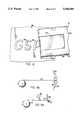
- FIG. 1is a perspective view showing a laminated web embodying this invention in the process of being cut on an automated sign making machine.
- FIG. 2is a perspective view of a portion of the web of FIG. 1 with parts of the various layer being broken away to reveal underlying layers.
- FIG. 3is a fragmentary vertical sectional view taken through the web of FIG. 1 wherein the thickness of the various layers have been exaggerated for clarity, the view showing the degree of penetration of the knife during the cutting of the web.
- FIGS. 4 through 8are views showing a portion of the web of FIG. 1 and illustrating in sequence the steps followed in using the web to create a sign.
- FIGS. 9a and 9billustrate schematically different embodiments of ways of applying the tack deadening means to form the web of FIG. 2.
- FIG. 1a web embodying the invention is illustrated at 10 and is shown in the process of being cut by an automated sign generating machine, such as that shown in U.S. Pat. No. 4,467,525, to which reference may be made for further details of its construction.
- the machine 12includes a knife 14 for cutting the web 10 mounted on a carriage 16 transversely of the web's length by sliding on two guide rails 18,18 and being driven transversely by a drive motor through an intermediary of a cable drive 20. Movement in the longitudinal or lengthwise extent of the web is effected by a pair of drive sprockets (not shown) which engage with feed holes 22,22 located on opposite sides of the web along marginal edge portions therealong for positively moving the web through the machine 12.
- the area of the web existing between the two marginal edge portionsis the work area off the web where the characters 24,24 are created. Therefore, by combined movement of the web in the longitudinal coordinate direction and the carrier in the transverse coordinate direction, the knife 14 is caused to cut any desired line on the work area of the web to produce cut characters, symbols or other shapes, such as shown at 24 in FIG. 1.
- the knifeis responsible for cutting such characters and the machine 12 includes a counter weight 26 which controls the pressure of the knife on the web. This enables the depth of penetration of the blade to be adjusted and held at a substantially consistent value as will be further explained in greater detail with reference to FIG. 3 wherein it is shown that the web is cut through less than the full extent of its thickness.
- FIGS. 2 and 3illustrate the construction of the web of FIG. 1.
- the web 10is comprised of a base layer or carrier sheet 28 and a superimposed sheet of sign material 30 carried by it.
- the web 10has a first layer of permanently tacky adhesive 32 interposed between the base layer 28 and the layer of sign material 30.
- the web 10is provided in accordance with the invention with a second permanently tacky adhesive layer 34 on the top of the layer of sign material 30 and the outwardly disposed surface 33 of this adhesive layer is provided with a means 35 removably covering the otherwise exposed tacky surface 33 effectively killing or deadening the tack of the second adhesive layer until such time as it is needed.
- the material selected for the sheets 28 and 30 and for the adhesive layers 32 and 34may vary, but in the preferred embodiment are those set out in table A-1 below.
- the base layer 28has a first face 36 and a second face 38 and the layer of sign material 30 has a first face 40 and a second face 42.
- the first faces 36 and 40face downwards and the second faces 38 and 40 face upwards taken relative to the manner in which the web is fed through the machine 12.
- the first face 40is the better appearing or "good" face of the sheet material as it will be the face seen on the finished sign.
- the good face 40in the case where the sign material is formed from a commonly available polyvinylchloride sheet of material, has a relatively smoother glossy finish which also serves as a release surface as will be appreciated hereinafter in accordance with one aspect of the invention. For the moment, it is only necessary to appreciate that the sign or good face being disposed downwards in contact with the permanently tacky adhesive 32 is protected from scratching or marring during the cutting operation.
- each of the carrier sheet 28 and the sign material sheet 30is adapted to strongly bond and thus remain attached to the one of the first and second adhesive layers associated with it. That is, the carrier sheet 28 is formed from a fibrous material, such as paper, which readily nonreleasably bonds to the first adhesive layer 32 while the back or second face 42 of the sign material sheet 30 is roughened or has a nonglossy face which readily lends itself to being nonreleasably bonded to the second permanently tacky adhesive layer 34.
- the first adhesive layer 32is sandwiched between the carrier layer 28 and the sign material 30 layer and releasably attaches to the sign material layer through the intermediary of the glossy face 40 serving as the release surface therebetween.
- the first adhesive layer 32 and the associated adherent faces 38 and 40are so related that this adhesive bonds more strongly to the face 38 than to the face 40. Further, the interface between the first adhesive layer 32 and the face 40 is such that the sign material of the layer 30 may be peeled from the adhesive layer 32 with the adhesive in the course of this peeling coming entirely free from the sign surface 40 and the remaining on the surface 38 of the base layer 28.
- the relative pull strengths of the adhesive layers 32 and 34are so selected relative to one another that the bonding force between the second adhesive layer 34 and both the face 42 of the sign material and the supporting surface will be greater than the bonding force between the face 40 and the first adhesive layer 32.
- This relationship of bonding strengthsmay be achieved by using an adhesive of greater tackiness for the layer 34 than that of the layer 32, and alternatively by making the first layer a relatively thin layer of adhesive sparsely distributed on the surface 38 while making the second layer 34 a relatively thick layer using more adhesive per unit area than that provided on the surface 38.
- the desired relationship of bonding strengthsmay also be obtained or enhanced by providing the face 40 of the layer of sign material with a film of release agent or otherwise conditioning it so as to yield a very low bonding strength between it and the adhesive layer 32 thus making the layer of sign material easily peeled from the confronting adhesive layer.
- the means 35may be applied to it in one of the two ways shown in FIGS. 9a and 9b depending on the form of material used.
- FIG. 9ait should be seen that the unconditioned web referred to as 10' is advanced with its tacky surface 33 outwardly exposed so as to be engaged by and bond with the adhesive deadening means 35.
- the means 35 in this exampleis comprised of a thin film of material 50 in sheet form which is caused to be superimposed on and held in place by the tacky exposed surface 33 of the web 10' as the two lengths are joined.
- FIG. 9ait should be seen that the unconditioned
- the means 35may be a coating of material 54 applied in liquid form in an evaporative solution by a sprayer 52 to the exposed tacky surface 33 of the unconditioned web 10' on which surface it thereafter becomes bonded.
- the coating 54may be air cured by a dryer blower 56 provided downstream of its application for this purpose.
- the material making up the means 35is capable of being substantially dissolved by the application of a given solvent applied to it, but which solvent being selected such that it does not adversely affect the tacky characteristic of the underlying surface 33 of the second adhesive layer 34 when applied.
- the solvent selected for reacting with the tack deadening means 35is preferably water.
- the material making up either the film 50 or the coating 54may take many forms, but in the preferred embodiment it is one of the materials listed below in TABLE A-2.
- the first step shown in FIG. 4is to cut one or more shapes 44,44 into the web using the blade 14.
- the shapesare cut in the reverse or mirror images of the desired shapes so that upon application to a substrate surface, the proper orientation is effected.
- the blade 14, as previously mentioned,is suspended above the web 10 in the sign machine 12 and is applied to the web with a downward force selected by the appropriate adjustment of the counterweight 26 such that the blade extends entirely through the coating or film of the means 35, through the second adhesive layer 34 and through the layer of sign material 30 during the cutting process, but penetrates at its tip only slightly, if at all, into the base layer 28.
- the cut characters 44,44being closed shapes, are completely separated from the remainder or the weed of the layer of sign material. These characters are nevertheless 32 interposed therebetween.
- a portion 46 of the layer of the sign material which contains the characters 44,44may be cut along the boundary lines 41,43 to separate it from the remainder of the layer 30.
- the web itselfcould be cut along such lines as 41 and 43 such that a portion of the web bounded by these margins is completely separated from remaining web material.
- waste material 45constituting the material of the layer 30 falling within the boundary lines 41,43 but not forming part of the characters, is weeded from the laminate 10 leaving behind on the base 28 the characters 44,44 in free standing form.
- Tweezers or other pointed pick-type toolsmay conveniently be used to efficiently preform the weeding process. It should be appreciated here that the tack deadening means 35 having conditioned the otherwise exposed tacky surface 33 in a manner heretofore discussed, permits weeding without interference from an otherwise tacky exposed surface.
- the cut closed shapes 44remain as free standing shapes separated from one another by the spacing dictated by the software employed for cutting the characters. It is important here to realize that the web of the present invention allows the characters after being cut in a mirrored image to be applied directly to the substrate surface in exactly the same spacing generated by the cutting machine 12 using the base layer 28. Where the material selected for the means 35 is one such as set forth in TABLE A-2 a brush 47 or other suitable solvent applying tool, such as a sponge, may be used to apply water enough to wash off the coating or film of the means 35.
- each boundary lineis spaced sufficiently far enough away from the characters or shapes that the solvent applied to the exposed surfaces of the characters may be activated without inadvertently contaminating the coating or film of the means 35 disposed on the material outside the boundary lines 41,43.
- the web 10is then transferred to and laid against a supporting surface 48 as shown in FIG. 7.
- the characters 44 cut from the layer 30 of the sign materialare then firmly adhered to the supporting surface by pressing the web 10 against that surface by means of a force applied to the base layer 28 in the area overlying the characters 44,44.
- Such forcemay be accomplished by pressing the base layer 28 with the thumb or index finger of the user or by burnishing it with a tool 51 as shown in FIG. 7.
- the base layer 28is peeled from the support surface 48 leaving behind the characters 44,44 now adhered to that surface. This is made possible by the bonding forces between the adhesive layer 32 and the involved adherent surfaces. As needed, the characters after being transferred to the supporting surface 48 may again be pressed downward using a roller or other pressing means to obtain a still stronger bond.
- the marginal edge portions of the webcould be formed without the openings 22 such that it is adapted to be gripped along these marginal edge portions in a suitable drive mechanism.
Landscapes
- Physics & Mathematics (AREA)
- General Physics & Mathematics (AREA)
- Engineering & Computer Science (AREA)
- Theoretical Computer Science (AREA)
- Adhesive Tapes (AREA)
- Laminated Bodies (AREA)
- Adhesives Or Adhesive Processes (AREA)
- Illuminated Signs And Luminous Advertising (AREA)
Abstract
Description
TABLE A-1 ______________________________________ Material Name Material Type Thickness ______________________________________base layer 28 heavy paper 8-10 mils 80 poundstock sign layer 30 colored flexible 2-4 mils plastic i.e. polyvinylchloride first adhesive rubber or acrylic 1-2mils layer 32 permanently tacky or pressure sensitive second adhesive rubber or acrylic 2-4mils layer 34 permanently tacky or pressure sensitive ______________________________________
TABLE A-2 ______________________________________ Applied Thickness Applied Material Type (Approximation) Solvent Form ______________________________________ Polyvinyl 1.5 mils or less Water Spray or Alcohol (PVA) Film Polyvinyl 1.5 mils or less Water Spray or Pyrrolidone Film (PVP) ______________________________________
Claims (13)
Priority Applications (8)
| Application Number | Priority Date | Filing Date | Title |
|---|---|---|---|
| US07/773,710US5344680A (en) | 1991-10-09 | 1991-10-09 | Sign making web with tack killing overcoat removable by washing and related method |
| DE69218332TDE69218332T2 (en) | 1991-10-09 | 1992-09-23 | Process for the production of signs using a washable anti-adhesive layer and device therefor |
| ES92203152TES2099791T3 (en) | 1991-10-09 | 1992-09-23 | CONTINUOUS SHEET TO PRODUCE SIGNS WITH WEAK-REMOVABLE STICK COATING REMOVABLE BY WASHING AND RELATED METHOD. |
| EP19920203152EP0536852B1 (en) | 1991-10-09 | 1992-09-23 | Sign making web with tack killing overcoat removable by washing and related method |
| CA 2079967CA2079967C (en) | 1991-10-09 | 1992-10-06 | Sign making web with tack killing overcoat removable by washing and related method |
| AU26314/92AAU646979B2 (en) | 1991-10-09 | 1992-10-08 | Sign making web with tack killing overcoat removable by washing and related method |
| JP27191492AJPH0643818A (en) | 1991-10-09 | 1992-10-09 | Sign preparation web and related method having tacky inhibiting coating removable by washing |
| US08/223,156US5466501A (en) | 1991-10-09 | 1994-04-05 | Sign making web with tack killing overcoat removable by washing and related method |
Applications Claiming Priority (1)
| Application Number | Priority Date | Filing Date | Title |
|---|---|---|---|
| US07/773,710US5344680A (en) | 1991-10-09 | 1991-10-09 | Sign making web with tack killing overcoat removable by washing and related method |
Related Child Applications (1)
| Application Number | Title | Priority Date | Filing Date |
|---|---|---|---|
| US08/223,156ContinuationUS5466501A (en) | 1991-10-09 | 1994-04-05 | Sign making web with tack killing overcoat removable by washing and related method |
Publications (1)
| Publication Number | Publication Date |
|---|---|
| US5344680Atrue US5344680A (en) | 1994-09-06 |
Family
ID=25099081
Family Applications (2)
| Application Number | Title | Priority Date | Filing Date |
|---|---|---|---|
| US07/773,710Expired - Fee RelatedUS5344680A (en) | 1991-10-09 | 1991-10-09 | Sign making web with tack killing overcoat removable by washing and related method |
| US08/223,156Expired - Fee RelatedUS5466501A (en) | 1991-10-09 | 1994-04-05 | Sign making web with tack killing overcoat removable by washing and related method |
Family Applications After (1)
| Application Number | Title | Priority Date | Filing Date |
|---|---|---|---|
| US08/223,156Expired - Fee RelatedUS5466501A (en) | 1991-10-09 | 1994-04-05 | Sign making web with tack killing overcoat removable by washing and related method |
Country Status (7)
| Country | Link |
|---|---|
| US (2) | US5344680A (en) |
| EP (1) | EP0536852B1 (en) |
| JP (1) | JPH0643818A (en) |
| AU (1) | AU646979B2 (en) |
| CA (1) | CA2079967C (en) |
| DE (1) | DE69218332T2 (en) |
| ES (1) | ES2099791T3 (en) |
Cited By (11)
| Publication number | Priority date | Publication date | Assignee | Title |
|---|---|---|---|---|
| US5466501A (en)* | 1991-10-09 | 1995-11-14 | Gerber Scientific Products, Inc. | Sign making web with tack killing overcoat removable by washing and related method |
| US5672408A (en)* | 1994-08-17 | 1997-09-30 | Elonex I.P. Holdings, Ltd. | Duplicate copies from a printer or copier |
| USD453179S1 (en) | 2000-07-27 | 2002-01-29 | Iimak | Printer cassette |
| USD458295S1 (en) | 2000-07-27 | 2002-06-04 | Iimak | Printer cassette |
| US6770360B2 (en) | 1998-06-12 | 2004-08-03 | Avery Dennison Corporation | Multilayered thermoplastic film and sign cutting method using the same |
| US6797103B2 (en) | 2001-03-12 | 2004-09-28 | Mikkelsen Graphic Engineering Inc. | Automatic waste-area removal method and apparatus |
| US6824639B1 (en)* | 1999-02-03 | 2004-11-30 | Contra Vision Ltd. | Partial imaging of a substrate with superimposed layers |
| US20040251902A1 (en)* | 2003-06-10 | 2004-12-16 | Kazumasa Takagi | Nuclear magnetic resonance equipment |
| US20050247173A1 (en)* | 2004-05-05 | 2005-11-10 | Peter Alsten | Automated method and apparatus for vision registration of graphics areas operating from the unprinted side |
| USD527761S1 (en) | 2005-02-17 | 2006-09-05 | International Imaging Materials, Inc. | Printer cassette |
| US8206523B1 (en) | 2008-05-14 | 2012-06-26 | Schillaci Sam P | Method of applying design to a substrate |
Families Citing this family (21)
| Publication number | Priority date | Publication date | Assignee | Title |
|---|---|---|---|---|
| GB2301693B (en)* | 1995-05-31 | 1999-09-15 | Projectgroen B V | Transferable signs |
| DE19531590C2 (en)* | 1995-08-28 | 1999-03-18 | Borsi Kg F | Use of a protective film made of plastic on a transparent carrier plate as a cover film |
| US6291044B1 (en) | 1995-12-05 | 2001-09-18 | John M. Chayka | Packaging tape |
| DE19612889A1 (en)* | 1996-03-30 | 1997-10-16 | Ko Jong Taik | Children's learning set |
| FR2755783B1 (en) | 1996-11-13 | 1998-12-24 | Chenel Guy G | PAINTED, FLEXIBLE, TEMPORARY DECORATIVE SURFACE, ESPECIALLY INTENDED TO BE EXPOSED TENTED OUTSIDE, SUCH AS DECORATIONS IN FRONT OF BUILDINGS, SIGNS |
| JP3885111B2 (en)* | 1997-06-03 | 2007-02-21 | スリーエム カンパニー | Multi-layer electronic cutting film for graphic images |
| US6585437B1 (en)* | 1999-09-27 | 2003-07-01 | Intermec Ip Corp. | Method and apparatus for reliable printing on linerless label stock |
| US6401616B1 (en)* | 2000-05-08 | 2002-06-11 | Gerber Scientific Products, Inc. | Method and material for making a coating blanket for use in printing presses |
| DE10114104B4 (en)* | 2001-03-23 | 2005-03-10 | Meto International Gmbh | Method and device for producing double labels and double labels |
| US7054708B1 (en)* | 2003-11-05 | 2006-05-30 | Xyron, Inc. | Sheet material cutting system and methods regarding same |
| US20070227332A1 (en)* | 2004-11-15 | 2007-10-04 | Xyron, Inc. | Automatic pattern making apparatus |
| WO2006055408A2 (en)* | 2004-11-15 | 2006-05-26 | Xyron, Inc. | Automatic pattern making apparatus |
| US7930958B2 (en) | 2005-07-14 | 2011-04-26 | Provo Craft And Novelty, Inc. | Blade housing for electronic cutting apparatus |
| US7893813B2 (en)* | 2005-07-28 | 2011-02-22 | Intermec Ip Corp. | Automatic data collection device, method and article |
| WO2007035863A2 (en) | 2005-09-21 | 2007-03-29 | Intermec Ip Corp. | Radio frequency identification tags based on coalition formation |
| US8120461B2 (en) | 2006-04-03 | 2012-02-21 | Intermec Ip Corp. | Automatic data collection device, method and article |
| US8002173B2 (en) | 2006-07-11 | 2011-08-23 | Intermec Ip Corp. | Automatic data collection device, method and article |
| US7579955B2 (en) | 2006-08-11 | 2009-08-25 | Intermec Ip Corp. | Device and method for selective backscattering of wireless communications signals |
| GB2455317B (en)* | 2007-12-05 | 2011-02-02 | Marshalls Mono Ltd | Garages |
| US20110280999A1 (en) | 2009-12-23 | 2011-11-17 | Provo Craft And Novelty, Inc. | Foodstuff Crafting Apparatus, Components, Assembly, and Method for Utilizing the Same |
| CN103999195B (en)* | 2011-12-15 | 2016-03-30 | 汉高知识产权控股有限责任公司 | Method for preparing adhesive film into pre-cut semiconductor wafer shape on dicing tape |
Citations (29)
| Publication number | Priority date | Publication date | Assignee | Title |
|---|---|---|---|---|
| US2578150A (en)* | 1947-12-12 | 1951-12-11 | Meyercord Co | Decalcomania and method of applying same |
| US2596179A (en)* | 1951-01-04 | 1952-05-13 | B B Chem Co | Supported adhesive sheet material unit and method of making the same |
| US2641562A (en)* | 1950-11-02 | 1953-06-09 | Victor E Chartrand | Decalcomania |
| US2907682A (en)* | 1958-05-28 | 1959-10-06 | Ncr Co | Adhesive tape containing pressurerupturable capsules |
| US3287192A (en)* | 1963-07-25 | 1966-11-22 | Pohlenz Armin | Method of producing self-adhesive labels, letters, characters and symbols |
| US3432376A (en)* | 1963-02-26 | 1969-03-11 | Letraset International Ltd | Dry transfer sheets and processes for using the same |
| US3532574A (en)* | 1966-06-22 | 1970-10-06 | Compac Corp | Method for the application of friable,pressure sensitive adhesive coated laminates |
| US3681179A (en)* | 1967-10-25 | 1972-08-01 | Minnesota Mining & Mfg | Moisture-resistant solar control film |
| US3728210A (en)* | 1969-06-27 | 1973-04-17 | J Piron | Dry transfer |
| GB1356426A (en)* | 1970-07-31 | 1974-06-12 | Burmetal Sa | Method of making marked surfaces |
| US3959555A (en)* | 1969-09-19 | 1976-05-25 | Polymark Corporation | Heat-sealable marking labels |
| GB2005596A (en)* | 1977-10-04 | 1979-04-25 | Letraset International Ltd | The manufacture of signs |
| US4182789A (en)* | 1978-08-03 | 1980-01-08 | T.M. Invention Associates | Multi-layer graphic arts tape system |
| US4248918A (en)* | 1978-06-07 | 1981-02-03 | Stauffer Chemical Company | Pressure sensitive products and adhesive formulations |
| JPS5628626A (en)* | 1979-08-15 | 1981-03-20 | Ngk Insulators Ltd | Treating method of extinguishment exhaust gas in room provided with electric power system |
| US4342614A (en)* | 1981-03-03 | 1982-08-03 | Minnesota Mining And Manufacturing Company | Pressure applicator for graphic transfer |
| US4355074A (en)* | 1979-06-30 | 1982-10-19 | Hoechst Aktiengesellschaft | Bonding sheet-like material to a substrate from which it can be dry-stripped |
| US4372070A (en)* | 1981-05-26 | 1983-02-08 | Egon Erlich | Adhesive sign and method of making |
| JPS5826987A (en)* | 1981-08-08 | 1983-02-17 | 富士電機株式会社 | metal melting furnace |
| US4467525A (en)* | 1982-07-26 | 1984-08-28 | Gerber Scientific Products, Inc. | Automated sign generator |
| US4495232A (en)* | 1981-04-22 | 1985-01-22 | Irion & Vosseler Gmbh & Co. & Zahlerfabrik | Stamping foils and methods |
| US4550683A (en)* | 1984-01-23 | 1985-11-05 | Jones Wallace R | Sheet construction and method |
| US4559732A (en)* | 1982-06-09 | 1985-12-24 | Klingshield South Africa (Proprietary) Limited | Method of applying signs |
| US4604153A (en)* | 1982-01-15 | 1986-08-05 | Kroy Inc. | Method of manufacturing figures from a laminated tape and applying the same to a desired medium |
| GB2187023A (en)* | 1986-02-24 | 1987-08-26 | Gerber Scient Products Inc | Laminated sign making web and method of using same |
| US4692198A (en)* | 1983-05-17 | 1987-09-08 | A/S Modulex | Method of printing a pattern on a surface receptive to sublimation printing |
| GB2189433A (en)* | 1986-04-25 | 1987-10-28 | Esselte Letraset Ltd | Dry transfer film materials for sign making |
| US4919994A (en)* | 1986-04-01 | 1990-04-24 | Minnesota Mining And Manufacturing Company | Dry transfer graphics article and methods of preparation and use thereof |
| US5026584A (en)* | 1987-05-29 | 1991-06-25 | Gerber Scientific Products, Inc. | Sign making web with dry adhesive layer |
Family Cites Families (2)
| Publication number | Priority date | Publication date | Assignee | Title |
|---|---|---|---|---|
| US5236751A (en)* | 1991-03-28 | 1993-08-17 | Reflexite Corporation | Cone collars with temporary release coating and method for making and assembling same |
| US5344680A (en)* | 1991-10-09 | 1994-09-06 | Gerber Scientific Products, Inc. | Sign making web with tack killing overcoat removable by washing and related method |
- 1991
- 1991-10-09USUS07/773,710patent/US5344680A/ennot_activeExpired - Fee Related
- 1992
- 1992-09-23DEDE69218332Tpatent/DE69218332T2/ennot_activeExpired - Fee Related
- 1992-09-23EPEP19920203152patent/EP0536852B1/ennot_activeExpired - Lifetime
- 1992-09-23ESES92203152Tpatent/ES2099791T3/ennot_activeExpired - Lifetime
- 1992-10-06CACA 2079967patent/CA2079967C/ennot_activeExpired - Fee Related
- 1992-10-08AUAU26314/92Apatent/AU646979B2/ennot_activeCeased
- 1992-10-09JPJP27191492Apatent/JPH0643818A/enactivePending
- 1994
- 1994-04-05USUS08/223,156patent/US5466501A/ennot_activeExpired - Fee Related
Patent Citations (29)
| Publication number | Priority date | Publication date | Assignee | Title |
|---|---|---|---|---|
| US2578150A (en)* | 1947-12-12 | 1951-12-11 | Meyercord Co | Decalcomania and method of applying same |
| US2641562A (en)* | 1950-11-02 | 1953-06-09 | Victor E Chartrand | Decalcomania |
| US2596179A (en)* | 1951-01-04 | 1952-05-13 | B B Chem Co | Supported adhesive sheet material unit and method of making the same |
| US2907682A (en)* | 1958-05-28 | 1959-10-06 | Ncr Co | Adhesive tape containing pressurerupturable capsules |
| US3432376A (en)* | 1963-02-26 | 1969-03-11 | Letraset International Ltd | Dry transfer sheets and processes for using the same |
| US3287192A (en)* | 1963-07-25 | 1966-11-22 | Pohlenz Armin | Method of producing self-adhesive labels, letters, characters and symbols |
| US3532574A (en)* | 1966-06-22 | 1970-10-06 | Compac Corp | Method for the application of friable,pressure sensitive adhesive coated laminates |
| US3681179A (en)* | 1967-10-25 | 1972-08-01 | Minnesota Mining & Mfg | Moisture-resistant solar control film |
| US3728210A (en)* | 1969-06-27 | 1973-04-17 | J Piron | Dry transfer |
| US3959555A (en)* | 1969-09-19 | 1976-05-25 | Polymark Corporation | Heat-sealable marking labels |
| GB1356426A (en)* | 1970-07-31 | 1974-06-12 | Burmetal Sa | Method of making marked surfaces |
| GB2005596A (en)* | 1977-10-04 | 1979-04-25 | Letraset International Ltd | The manufacture of signs |
| US4248918A (en)* | 1978-06-07 | 1981-02-03 | Stauffer Chemical Company | Pressure sensitive products and adhesive formulations |
| US4182789A (en)* | 1978-08-03 | 1980-01-08 | T.M. Invention Associates | Multi-layer graphic arts tape system |
| US4355074A (en)* | 1979-06-30 | 1982-10-19 | Hoechst Aktiengesellschaft | Bonding sheet-like material to a substrate from which it can be dry-stripped |
| JPS5628626A (en)* | 1979-08-15 | 1981-03-20 | Ngk Insulators Ltd | Treating method of extinguishment exhaust gas in room provided with electric power system |
| US4342614A (en)* | 1981-03-03 | 1982-08-03 | Minnesota Mining And Manufacturing Company | Pressure applicator for graphic transfer |
| US4495232A (en)* | 1981-04-22 | 1985-01-22 | Irion & Vosseler Gmbh & Co. & Zahlerfabrik | Stamping foils and methods |
| US4372070A (en)* | 1981-05-26 | 1983-02-08 | Egon Erlich | Adhesive sign and method of making |
| JPS5826987A (en)* | 1981-08-08 | 1983-02-17 | 富士電機株式会社 | metal melting furnace |
| US4604153A (en)* | 1982-01-15 | 1986-08-05 | Kroy Inc. | Method of manufacturing figures from a laminated tape and applying the same to a desired medium |
| US4559732A (en)* | 1982-06-09 | 1985-12-24 | Klingshield South Africa (Proprietary) Limited | Method of applying signs |
| US4467525A (en)* | 1982-07-26 | 1984-08-28 | Gerber Scientific Products, Inc. | Automated sign generator |
| US4692198A (en)* | 1983-05-17 | 1987-09-08 | A/S Modulex | Method of printing a pattern on a surface receptive to sublimation printing |
| US4550683A (en)* | 1984-01-23 | 1985-11-05 | Jones Wallace R | Sheet construction and method |
| GB2187023A (en)* | 1986-02-24 | 1987-08-26 | Gerber Scient Products Inc | Laminated sign making web and method of using same |
| US4919994A (en)* | 1986-04-01 | 1990-04-24 | Minnesota Mining And Manufacturing Company | Dry transfer graphics article and methods of preparation and use thereof |
| GB2189433A (en)* | 1986-04-25 | 1987-10-28 | Esselte Letraset Ltd | Dry transfer film materials for sign making |
| US5026584A (en)* | 1987-05-29 | 1991-06-25 | Gerber Scientific Products, Inc. | Sign making web with dry adhesive layer |
Cited By (12)
| Publication number | Priority date | Publication date | Assignee | Title |
|---|---|---|---|---|
| US5466501A (en)* | 1991-10-09 | 1995-11-14 | Gerber Scientific Products, Inc. | Sign making web with tack killing overcoat removable by washing and related method |
| US5672408A (en)* | 1994-08-17 | 1997-09-30 | Elonex I.P. Holdings, Ltd. | Duplicate copies from a printer or copier |
| US6770360B2 (en) | 1998-06-12 | 2004-08-03 | Avery Dennison Corporation | Multilayered thermoplastic film and sign cutting method using the same |
| US6824639B1 (en)* | 1999-02-03 | 2004-11-30 | Contra Vision Ltd. | Partial imaging of a substrate with superimposed layers |
| USD453179S1 (en) | 2000-07-27 | 2002-01-29 | Iimak | Printer cassette |
| USD458295S1 (en) | 2000-07-27 | 2002-06-04 | Iimak | Printer cassette |
| US6797103B2 (en) | 2001-03-12 | 2004-09-28 | Mikkelsen Graphic Engineering Inc. | Automatic waste-area removal method and apparatus |
| US20040251902A1 (en)* | 2003-06-10 | 2004-12-16 | Kazumasa Takagi | Nuclear magnetic resonance equipment |
| US20050247173A1 (en)* | 2004-05-05 | 2005-11-10 | Peter Alsten | Automated method and apparatus for vision registration of graphics areas operating from the unprinted side |
| US7140283B2 (en) | 2004-05-05 | 2006-11-28 | Mikkelsen Graphic Engineering | Automated method and apparatus for vision registration of graphics areas operating from the unprinted side |
| USD527761S1 (en) | 2005-02-17 | 2006-09-05 | International Imaging Materials, Inc. | Printer cassette |
| US8206523B1 (en) | 2008-05-14 | 2012-06-26 | Schillaci Sam P | Method of applying design to a substrate |
Also Published As
| Publication number | Publication date |
|---|---|
| AU646979B2 (en) | 1994-03-10 |
| CA2079967A1 (en) | 1993-04-10 |
| AU2631492A (en) | 1993-04-29 |
| DE69218332D1 (en) | 1997-04-24 |
| DE69218332T2 (en) | 1997-07-03 |
| CA2079967C (en) | 1999-07-20 |
| EP0536852B1 (en) | 1997-03-19 |
| US5466501A (en) | 1995-11-14 |
| JPH0643818A (en) | 1994-02-18 |
| EP0536852A2 (en) | 1993-04-14 |
| ES2099791T3 (en) | 1997-06-01 |
| EP0536852A3 (en) | 1994-11-23 |
Similar Documents
| Publication | Publication Date | Title |
|---|---|---|
| US5344680A (en) | Sign making web with tack killing overcoat removable by washing and related method | |
| US5026584A (en) | Sign making web with dry adhesive layer | |
| US4405401A (en) | Thermoplastic labeling and method of making same | |
| EP0650154B1 (en) | Labels and manufacture thereof | |
| US5288358A (en) | Sign making web with dry adhesive layer and method of using the same | |
| US5106450A (en) | Dry film resist transport and lamination system for semiconductor wafers | |
| US5124187A (en) | Adhesive sheet materials for signmaking machines | |
| JPS62198890A (en) | Multilayer web for preparation mark and use thereof | |
| US3145514A (en) | Method for packaging appliques | |
| US4986573A (en) | Layout sheet | |
| GB2218682A (en) | Peel-off self adhesive stickers and labels | |
| JPH1173109A (en) | Sticking label for cylindrical body | |
| DE69112646D1 (en) | METHOD AND DEVICE FOR PRODUCING LABELS. | |
| JPH0679812A (en) | Continuous printing machine of seal and label | |
| JP2002011452A (en) | Method for releasing marking adhesive sheet and releasing method | |
| JP2000160111A (en) | Tattoo sticker | |
| JPH0118597Y2 (en) | ||
| EP0100658A2 (en) | Labelling tapes | |
| JPS6224027B2 (en) | ||
| JPH06172724A (en) | Pressure-sensitive decorative sheet | |
| JPH02123394A (en) | Cutting method for surface base material leaving backing mount | |
| JP2838093B2 (en) | Method for producing laminated paper having slits | |
| JPH02210386A (en) | Partial peeling method for sheet-like object | |
| JPH0616726Y2 (en) | Label making device | |
| JPH086555Y2 (en) | Application sheet for separate marking |
Legal Events
| Date | Code | Title | Description |
|---|---|---|---|
| AS | Assignment | Owner name:GERBER SCIENTIFIC PRODUCTS, INC. A CORP. OF CON Free format text:ASSIGNMENT OF ASSIGNORS INTEREST.;ASSIGNORS:LOGAN, DAVID J.;RICH, LEONARD G.;REEL/FRAME:005878/0125 Effective date:19911009 | |
| CC | Certificate of correction | ||
| FPAY | Fee payment | Year of fee payment:4 | |
| FPAY | Fee payment | Year of fee payment:8 | |
| AS | Assignment | Owner name:ABLECO FINANCE LLC, AS COLLATERAL AGENT, NEW YORK Free format text:ASSIGNMENT FOR SECURITY;ASSIGNORS:GERBER SCIENTIFIC, INC.;GERBER SCIENTIFIC INTERNATIONAL, INC. (AS SUCCESSOR IN INTEREST TO GERBER TECHNOLOGY, INC.;GERBER SCIENTIFIC PRODUCTS, INC., A CONNECTICUT CORPORATION;AND OTHERS;REEL/FRAME:014344/0767 Effective date:20030509 | |
| AS | Assignment | Owner name:FLEET CAPITAL CORPORATION, AS AGENT, CONNECTICUT Free format text:SECURITY AGREEMENT;ASSIGNORS:GERBER SCIENTIFIC, INC.;GERBER SCIENTIFIC INTERNATIONAL, INC.;GERBER COBURN OPTICAL, INC.;AND OTHERS;REEL/FRAME:014624/0770 Effective date:20030509 | |
| FEPP | Fee payment procedure | Free format text:PAYOR NUMBER ASSIGNED (ORIGINAL EVENT CODE: ASPN); ENTITY STATUS OF PATENT OWNER: LARGE ENTITY | |
| AS | Assignment | Owner name:CITIZENS BANK OF MASSACHUSETTS, MASSACHUSETTS Free format text:INTELLECTUAL PROPERTY SECURITY AGREEMENT;ASSIGNOR:GERBER SCIENTIFIC, INC.;REEL/FRAME:017097/0668 Effective date:20051031 | |
| REMI | Maintenance fee reminder mailed | ||
| LAPS | Lapse for failure to pay maintenance fees | ||
| STCH | Information on status: patent discontinuation | Free format text:PATENT EXPIRED DUE TO NONPAYMENT OF MAINTENANCE FEES UNDER 37 CFR 1.362 | |
| FP | Lapsed due to failure to pay maintenance fee | Effective date:20060906 | |
| AS | Assignment | Owner name:GERBER SCIENTIFIC INC., CONNECTICUT Free format text:TERMINATION AND RELEASE OF SECURITY INTEREST IN INTELLECTUAL PROPERTY;ASSIGNOR:RBS CITIZENS, N.A. A NATIONAL BANKING ASSOCIATION AND SUCCESSOR TO CITIZENS BANK OF MASSACHUSETTS, A MASSACHUSETTS BANK;REEL/FRAME:026795/0056 Effective date:20110822 Owner name:GERBER SCIENTIFIC INTERNATIONAL INC., CONNECTICUT Free format text:TERMINATION AND RELEASE OF SECURITY INTEREST IN INTELLECTUAL PROPERTY;ASSIGNOR:RBS CITIZENS, N.A. A NATIONAL BANKING ASSOCIATION AND SUCCESSOR TO CITIZENS BANK OF MASSACHUSETTS, A MASSACHUSETTS BANK;REEL/FRAME:026795/0056 Effective date:20110822 | |
| AS | Assignment | Owner name:GERBER COBURN OPTICAL, INC., CONNECTICUT Free format text:RELEASE OF ASSIGNMENT OF SECURITY - PATENTS;ASSIGNOR:ABLECO FINANCE LLC;REEL/FRAME:026962/0037 Effective date:20110922 Owner name:GERBER SCIENTIFIC INTERNATIONAL INC., CONNECTICUT Free format text:RELEASE OF ASSIGNMENT OF SECURITY - PATENTS;ASSIGNOR:ABLECO FINANCE LLC;REEL/FRAME:026962/0037 Effective date:20110922 Owner name:GERBER SCIENTIFIC, INC., CONNECTICUT Free format text:RELEASE OF ASSIGNMENT OF SECURITY - PATENTS;ASSIGNOR:ABLECO FINANCE LLC;REEL/FRAME:026962/0037 Effective date:20110922 |