US5344458A - Arthroplasty component - Google Patents
Arthroplasty componentDownload PDFInfo
- Publication number
- US5344458A US5344458AUS07/926,481US92648192AUS5344458AUS 5344458 AUS5344458 AUS 5344458AUS 92648192 AUS92648192 AUS 92648192AUS 5344458 AUS5344458 AUS 5344458A
- Authority
- US
- United States
- Prior art keywords
- bone
- tab
- tray
- cortical
- engaging
- Prior art date
- Legal status (The legal status is an assumption and is not a legal conclusion. Google has not performed a legal analysis and makes no representation as to the accuracy of the status listed.)
- Expired - Lifetime
Links
Images


Classifications
- A—HUMAN NECESSITIES
- A61—MEDICAL OR VETERINARY SCIENCE; HYGIENE
- A61L—METHODS OR APPARATUS FOR STERILISING MATERIALS OR OBJECTS IN GENERAL; DISINFECTION, STERILISATION OR DEODORISATION OF AIR; CHEMICAL ASPECTS OF BANDAGES, DRESSINGS, ABSORBENT PADS OR SURGICAL ARTICLES; MATERIALS FOR BANDAGES, DRESSINGS, ABSORBENT PADS OR SURGICAL ARTICLES
- A61L27/00—Materials for grafts or prostheses or for coating grafts or prostheses
- A61L27/40—Composite materials, i.e. containing one material dispersed in a matrix of the same or different material
- A61L27/44—Composite materials, i.e. containing one material dispersed in a matrix of the same or different material having a macromolecular matrix
- A61L27/443—Composite materials, i.e. containing one material dispersed in a matrix of the same or different material having a macromolecular matrix with carbon fillers
- A—HUMAN NECESSITIES
- A61—MEDICAL OR VETERINARY SCIENCE; HYGIENE
- A61B—DIAGNOSIS; SURGERY; IDENTIFICATION
- A61B17/00—Surgical instruments, devices or methods
- A61B17/56—Surgical instruments or methods for treatment of bones or joints; Devices specially adapted therefor
- A61B17/58—Surgical instruments or methods for treatment of bones or joints; Devices specially adapted therefor for osteosynthesis, e.g. bone plates, screws or setting implements
- A61B17/68—Internal fixation devices, including fasteners and spinal fixators, even if a part thereof projects from the skin
- A61B17/84—Fasteners therefor or fasteners being internal fixation devices
- A61B17/86—Pins or screws or threaded wires; nuts therefor
- A61B17/8625—Shanks, i.e. parts contacting bone tissue
- A61B17/863—Shanks, i.e. parts contacting bone tissue with thread interrupted or changing its form along shank, other than constant taper
- A—HUMAN NECESSITIES
- A61—MEDICAL OR VETERINARY SCIENCE; HYGIENE
- A61F—FILTERS IMPLANTABLE INTO BLOOD VESSELS; PROSTHESES; DEVICES PROVIDING PATENCY TO, OR PREVENTING COLLAPSING OF, TUBULAR STRUCTURES OF THE BODY, e.g. STENTS; ORTHOPAEDIC, NURSING OR CONTRACEPTIVE DEVICES; FOMENTATION; TREATMENT OR PROTECTION OF EYES OR EARS; BANDAGES, DRESSINGS OR ABSORBENT PADS; FIRST-AID KITS
- A61F2/00—Filters implantable into blood vessels; Prostheses, i.e. artificial substitutes or replacements for parts of the body; Appliances for connecting them with the body; Devices providing patency to, or preventing collapsing of, tubular structures of the body, e.g. stents
- A61F2/02—Prostheses implantable into the body
- A61F2/30—Joints
- A61F2/3094—Designing or manufacturing processes
- A61F2/30965—Reinforcing the prosthesis by embedding particles or fibres during moulding or dipping
- A—HUMAN NECESSITIES
- A61—MEDICAL OR VETERINARY SCIENCE; HYGIENE
- A61F—FILTERS IMPLANTABLE INTO BLOOD VESSELS; PROSTHESES; DEVICES PROVIDING PATENCY TO, OR PREVENTING COLLAPSING OF, TUBULAR STRUCTURES OF THE BODY, e.g. STENTS; ORTHOPAEDIC, NURSING OR CONTRACEPTIVE DEVICES; FOMENTATION; TREATMENT OR PROTECTION OF EYES OR EARS; BANDAGES, DRESSINGS OR ABSORBENT PADS; FIRST-AID KITS
- A61F2/00—Filters implantable into blood vessels; Prostheses, i.e. artificial substitutes or replacements for parts of the body; Appliances for connecting them with the body; Devices providing patency to, or preventing collapsing of, tubular structures of the body, e.g. stents
- A61F2/02—Prostheses implantable into the body
- A61F2/30—Joints
- A61F2/38—Joints for elbows or knees
- A61F2/3877—Patellae or trochleae
- A—HUMAN NECESSITIES
- A61—MEDICAL OR VETERINARY SCIENCE; HYGIENE
- A61F—FILTERS IMPLANTABLE INTO BLOOD VESSELS; PROSTHESES; DEVICES PROVIDING PATENCY TO, OR PREVENTING COLLAPSING OF, TUBULAR STRUCTURES OF THE BODY, e.g. STENTS; ORTHOPAEDIC, NURSING OR CONTRACEPTIVE DEVICES; FOMENTATION; TREATMENT OR PROTECTION OF EYES OR EARS; BANDAGES, DRESSINGS OR ABSORBENT PADS; FIRST-AID KITS
- A61F2/00—Filters implantable into blood vessels; Prostheses, i.e. artificial substitutes or replacements for parts of the body; Appliances for connecting them with the body; Devices providing patency to, or preventing collapsing of, tubular structures of the body, e.g. stents
- A61F2/02—Prostheses implantable into the body
- A61F2/30—Joints
- A61F2/38—Joints for elbows or knees
- A61F2/389—Tibial components
- A—HUMAN NECESSITIES
- A61—MEDICAL OR VETERINARY SCIENCE; HYGIENE
- A61F—FILTERS IMPLANTABLE INTO BLOOD VESSELS; PROSTHESES; DEVICES PROVIDING PATENCY TO, OR PREVENTING COLLAPSING OF, TUBULAR STRUCTURES OF THE BODY, e.g. STENTS; ORTHOPAEDIC, NURSING OR CONTRACEPTIVE DEVICES; FOMENTATION; TREATMENT OR PROTECTION OF EYES OR EARS; BANDAGES, DRESSINGS OR ABSORBENT PADS; FIRST-AID KITS
- A61F2/00—Filters implantable into blood vessels; Prostheses, i.e. artificial substitutes or replacements for parts of the body; Appliances for connecting them with the body; Devices providing patency to, or preventing collapsing of, tubular structures of the body, e.g. stents
- A61F2/02—Prostheses implantable into the body
- A61F2/30—Joints
- A61F2/40—Joints for shoulders
- A61F2/4081—Glenoid components, e.g. cups
- A—HUMAN NECESSITIES
- A61—MEDICAL OR VETERINARY SCIENCE; HYGIENE
- A61L—METHODS OR APPARATUS FOR STERILISING MATERIALS OR OBJECTS IN GENERAL; DISINFECTION, STERILISATION OR DEODORISATION OF AIR; CHEMICAL ASPECTS OF BANDAGES, DRESSINGS, ABSORBENT PADS OR SURGICAL ARTICLES; MATERIALS FOR BANDAGES, DRESSINGS, ABSORBENT PADS OR SURGICAL ARTICLES
- A61L27/00—Materials for grafts or prostheses or for coating grafts or prostheses
- A61L27/40—Composite materials, i.e. containing one material dispersed in a matrix of the same or different material
- A61L27/44—Composite materials, i.e. containing one material dispersed in a matrix of the same or different material having a macromolecular matrix
- A61L27/48—Composite materials, i.e. containing one material dispersed in a matrix of the same or different material having a macromolecular matrix with macromolecular fillers
- A—HUMAN NECESSITIES
- A61—MEDICAL OR VETERINARY SCIENCE; HYGIENE
- A61B—DIAGNOSIS; SURGERY; IDENTIFICATION
- A61B17/00—Surgical instruments, devices or methods
- A61B17/56—Surgical instruments or methods for treatment of bones or joints; Devices specially adapted therefor
- A61B17/58—Surgical instruments or methods for treatment of bones or joints; Devices specially adapted therefor for osteosynthesis, e.g. bone plates, screws or setting implements
- A61B17/68—Internal fixation devices, including fasteners and spinal fixators, even if a part thereof projects from the skin
- A61B17/84—Fasteners therefor or fasteners being internal fixation devices
- A61B17/86—Pins or screws or threaded wires; nuts therefor
- A—HUMAN NECESSITIES
- A61—MEDICAL OR VETERINARY SCIENCE; HYGIENE
- A61F—FILTERS IMPLANTABLE INTO BLOOD VESSELS; PROSTHESES; DEVICES PROVIDING PATENCY TO, OR PREVENTING COLLAPSING OF, TUBULAR STRUCTURES OF THE BODY, e.g. STENTS; ORTHOPAEDIC, NURSING OR CONTRACEPTIVE DEVICES; FOMENTATION; TREATMENT OR PROTECTION OF EYES OR EARS; BANDAGES, DRESSINGS OR ABSORBENT PADS; FIRST-AID KITS
- A61F2/00—Filters implantable into blood vessels; Prostheses, i.e. artificial substitutes or replacements for parts of the body; Appliances for connecting them with the body; Devices providing patency to, or preventing collapsing of, tubular structures of the body, e.g. stents
- A61F2/02—Prostheses implantable into the body
- A61F2/30—Joints
- A61F2002/30001—Additional features of subject-matter classified in A61F2/28, A61F2/30 and subgroups thereof
- A61F2002/30108—Shapes
- A61F2002/3011—Cross-sections or two-dimensional shapes
- A61F2002/30112—Rounded shapes, e.g. with rounded corners
- A—HUMAN NECESSITIES
- A61—MEDICAL OR VETERINARY SCIENCE; HYGIENE
- A61F—FILTERS IMPLANTABLE INTO BLOOD VESSELS; PROSTHESES; DEVICES PROVIDING PATENCY TO, OR PREVENTING COLLAPSING OF, TUBULAR STRUCTURES OF THE BODY, e.g. STENTS; ORTHOPAEDIC, NURSING OR CONTRACEPTIVE DEVICES; FOMENTATION; TREATMENT OR PROTECTION OF EYES OR EARS; BANDAGES, DRESSINGS OR ABSORBENT PADS; FIRST-AID KITS
- A61F2/00—Filters implantable into blood vessels; Prostheses, i.e. artificial substitutes or replacements for parts of the body; Appliances for connecting them with the body; Devices providing patency to, or preventing collapsing of, tubular structures of the body, e.g. stents
- A61F2/02—Prostheses implantable into the body
- A61F2/30—Joints
- A61F2002/30001—Additional features of subject-matter classified in A61F2/28, A61F2/30 and subgroups thereof
- A61F2002/30108—Shapes
- A61F2002/3011—Cross-sections or two-dimensional shapes
- A61F2002/30138—Convex polygonal shapes
- A61F2002/30156—Convex polygonal shapes triangular
- A—HUMAN NECESSITIES
- A61—MEDICAL OR VETERINARY SCIENCE; HYGIENE
- A61F—FILTERS IMPLANTABLE INTO BLOOD VESSELS; PROSTHESES; DEVICES PROVIDING PATENCY TO, OR PREVENTING COLLAPSING OF, TUBULAR STRUCTURES OF THE BODY, e.g. STENTS; ORTHOPAEDIC, NURSING OR CONTRACEPTIVE DEVICES; FOMENTATION; TREATMENT OR PROTECTION OF EYES OR EARS; BANDAGES, DRESSINGS OR ABSORBENT PADS; FIRST-AID KITS
- A61F2/00—Filters implantable into blood vessels; Prostheses, i.e. artificial substitutes or replacements for parts of the body; Appliances for connecting them with the body; Devices providing patency to, or preventing collapsing of, tubular structures of the body, e.g. stents
- A61F2/02—Prostheses implantable into the body
- A61F2/30—Joints
- A61F2002/30001—Additional features of subject-matter classified in A61F2/28, A61F2/30 and subgroups thereof
- A61F2002/30316—The prosthesis having different structural features at different locations within the same prosthesis; Connections between prosthetic parts; Special structural features of bone or joint prostheses not otherwise provided for
- A61F2002/30329—Connections or couplings between prosthetic parts, e.g. between modular parts; Connecting elements
- A61F2002/30331—Connections or couplings between prosthetic parts, e.g. between modular parts; Connecting elements made by longitudinally pushing a protrusion into a complementarily-shaped recess, e.g. held by friction fit
- A61F2002/30332—Conically- or frustoconically-shaped protrusion and recess
- A—HUMAN NECESSITIES
- A61—MEDICAL OR VETERINARY SCIENCE; HYGIENE
- A61F—FILTERS IMPLANTABLE INTO BLOOD VESSELS; PROSTHESES; DEVICES PROVIDING PATENCY TO, OR PREVENTING COLLAPSING OF, TUBULAR STRUCTURES OF THE BODY, e.g. STENTS; ORTHOPAEDIC, NURSING OR CONTRACEPTIVE DEVICES; FOMENTATION; TREATMENT OR PROTECTION OF EYES OR EARS; BANDAGES, DRESSINGS OR ABSORBENT PADS; FIRST-AID KITS
- A61F2/00—Filters implantable into blood vessels; Prostheses, i.e. artificial substitutes or replacements for parts of the body; Appliances for connecting them with the body; Devices providing patency to, or preventing collapsing of, tubular structures of the body, e.g. stents
- A61F2/02—Prostheses implantable into the body
- A61F2/30—Joints
- A61F2002/30001—Additional features of subject-matter classified in A61F2/28, A61F2/30 and subgroups thereof
- A61F2002/30316—The prosthesis having different structural features at different locations within the same prosthesis; Connections between prosthetic parts; Special structural features of bone or joint prostheses not otherwise provided for
- A61F2002/30535—Special structural features of bone or joint prostheses not otherwise provided for
- A61F2002/30576—Special structural features of bone or joint prostheses not otherwise provided for with extending fixation tabs
- A61F2002/30578—Special structural features of bone or joint prostheses not otherwise provided for with extending fixation tabs having apertures, e.g. for receiving fixation screws
- A—HUMAN NECESSITIES
- A61—MEDICAL OR VETERINARY SCIENCE; HYGIENE
- A61F—FILTERS IMPLANTABLE INTO BLOOD VESSELS; PROSTHESES; DEVICES PROVIDING PATENCY TO, OR PREVENTING COLLAPSING OF, TUBULAR STRUCTURES OF THE BODY, e.g. STENTS; ORTHOPAEDIC, NURSING OR CONTRACEPTIVE DEVICES; FOMENTATION; TREATMENT OR PROTECTION OF EYES OR EARS; BANDAGES, DRESSINGS OR ABSORBENT PADS; FIRST-AID KITS
- A61F2/00—Filters implantable into blood vessels; Prostheses, i.e. artificial substitutes or replacements for parts of the body; Appliances for connecting them with the body; Devices providing patency to, or preventing collapsing of, tubular structures of the body, e.g. stents
- A61F2/02—Prostheses implantable into the body
- A61F2/30—Joints
- A61F2/30767—Special external or bone-contacting surface, e.g. coating for improving bone ingrowth
- A61F2/30771—Special external or bone-contacting surface, e.g. coating for improving bone ingrowth applied in original prostheses, e.g. holes or grooves
- A61F2002/30772—Apertures or holes, e.g. of circular cross section
- A61F2002/30782—Apertures or holes, e.g. of circular cross section inclined obliquely
- A—HUMAN NECESSITIES
- A61—MEDICAL OR VETERINARY SCIENCE; HYGIENE
- A61F—FILTERS IMPLANTABLE INTO BLOOD VESSELS; PROSTHESES; DEVICES PROVIDING PATENCY TO, OR PREVENTING COLLAPSING OF, TUBULAR STRUCTURES OF THE BODY, e.g. STENTS; ORTHOPAEDIC, NURSING OR CONTRACEPTIVE DEVICES; FOMENTATION; TREATMENT OR PROTECTION OF EYES OR EARS; BANDAGES, DRESSINGS OR ABSORBENT PADS; FIRST-AID KITS
- A61F2/00—Filters implantable into blood vessels; Prostheses, i.e. artificial substitutes or replacements for parts of the body; Appliances for connecting them with the body; Devices providing patency to, or preventing collapsing of, tubular structures of the body, e.g. stents
- A61F2/02—Prostheses implantable into the body
- A61F2/30—Joints
- A61F2/30767—Special external or bone-contacting surface, e.g. coating for improving bone ingrowth
- A61F2/30771—Special external or bone-contacting surface, e.g. coating for improving bone ingrowth applied in original prostheses, e.g. holes or grooves
- A61F2002/30772—Apertures or holes, e.g. of circular cross section
- A61F2002/3079—Stepped or enlarged apertures, e.g. having discrete diameter changes
- A—HUMAN NECESSITIES
- A61—MEDICAL OR VETERINARY SCIENCE; HYGIENE
- A61F—FILTERS IMPLANTABLE INTO BLOOD VESSELS; PROSTHESES; DEVICES PROVIDING PATENCY TO, OR PREVENTING COLLAPSING OF, TUBULAR STRUCTURES OF THE BODY, e.g. STENTS; ORTHOPAEDIC, NURSING OR CONTRACEPTIVE DEVICES; FOMENTATION; TREATMENT OR PROTECTION OF EYES OR EARS; BANDAGES, DRESSINGS OR ABSORBENT PADS; FIRST-AID KITS
- A61F2/00—Filters implantable into blood vessels; Prostheses, i.e. artificial substitutes or replacements for parts of the body; Appliances for connecting them with the body; Devices providing patency to, or preventing collapsing of, tubular structures of the body, e.g. stents
- A61F2/02—Prostheses implantable into the body
- A61F2/30—Joints
- A61F2/30767—Special external or bone-contacting surface, e.g. coating for improving bone ingrowth
- A61F2/30771—Special external or bone-contacting surface, e.g. coating for improving bone ingrowth applied in original prostheses, e.g. holes or grooves
- A61F2002/30795—Blind bores, e.g. of circular cross-section
- A61F2002/30807—Plurality of blind bores
- A61F2002/30808—Plurality of blind bores parallel
- A—HUMAN NECESSITIES
- A61—MEDICAL OR VETERINARY SCIENCE; HYGIENE
- A61F—FILTERS IMPLANTABLE INTO BLOOD VESSELS; PROSTHESES; DEVICES PROVIDING PATENCY TO, OR PREVENTING COLLAPSING OF, TUBULAR STRUCTURES OF THE BODY, e.g. STENTS; ORTHOPAEDIC, NURSING OR CONTRACEPTIVE DEVICES; FOMENTATION; TREATMENT OR PROTECTION OF EYES OR EARS; BANDAGES, DRESSINGS OR ABSORBENT PADS; FIRST-AID KITS
- A61F2/00—Filters implantable into blood vessels; Prostheses, i.e. artificial substitutes or replacements for parts of the body; Appliances for connecting them with the body; Devices providing patency to, or preventing collapsing of, tubular structures of the body, e.g. stents
- A61F2/02—Prostheses implantable into the body
- A61F2/30—Joints
- A61F2/30767—Special external or bone-contacting surface, e.g. coating for improving bone ingrowth
- A61F2/30771—Special external or bone-contacting surface, e.g. coating for improving bone ingrowth applied in original prostheses, e.g. holes or grooves
- A61F2002/30841—Sharp anchoring protrusions for impaction into the bone, e.g. sharp pins, spikes
- A—HUMAN NECESSITIES
- A61—MEDICAL OR VETERINARY SCIENCE; HYGIENE
- A61F—FILTERS IMPLANTABLE INTO BLOOD VESSELS; PROSTHESES; DEVICES PROVIDING PATENCY TO, OR PREVENTING COLLAPSING OF, TUBULAR STRUCTURES OF THE BODY, e.g. STENTS; ORTHOPAEDIC, NURSING OR CONTRACEPTIVE DEVICES; FOMENTATION; TREATMENT OR PROTECTION OF EYES OR EARS; BANDAGES, DRESSINGS OR ABSORBENT PADS; FIRST-AID KITS
- A61F2/00—Filters implantable into blood vessels; Prostheses, i.e. artificial substitutes or replacements for parts of the body; Appliances for connecting them with the body; Devices providing patency to, or preventing collapsing of, tubular structures of the body, e.g. stents
- A61F2/02—Prostheses implantable into the body
- A61F2/30—Joints
- A61F2/30767—Special external or bone-contacting surface, e.g. coating for improving bone ingrowth
- A61F2/30771—Special external or bone-contacting surface, e.g. coating for improving bone ingrowth applied in original prostheses, e.g. holes or grooves
- A61F2002/30878—Special external or bone-contacting surface, e.g. coating for improving bone ingrowth applied in original prostheses, e.g. holes or grooves with non-sharp protrusions, for instance contacting the bone for anchoring, e.g. keels, pegs, pins, posts, shanks, stems, struts
- A61F2002/30884—Fins or wings, e.g. longitudinal wings for preventing rotation within the bone cavity
- A—HUMAN NECESSITIES
- A61—MEDICAL OR VETERINARY SCIENCE; HYGIENE
- A61F—FILTERS IMPLANTABLE INTO BLOOD VESSELS; PROSTHESES; DEVICES PROVIDING PATENCY TO, OR PREVENTING COLLAPSING OF, TUBULAR STRUCTURES OF THE BODY, e.g. STENTS; ORTHOPAEDIC, NURSING OR CONTRACEPTIVE DEVICES; FOMENTATION; TREATMENT OR PROTECTION OF EYES OR EARS; BANDAGES, DRESSINGS OR ABSORBENT PADS; FIRST-AID KITS
- A61F2/00—Filters implantable into blood vessels; Prostheses, i.e. artificial substitutes or replacements for parts of the body; Appliances for connecting them with the body; Devices providing patency to, or preventing collapsing of, tubular structures of the body, e.g. stents
- A61F2/02—Prostheses implantable into the body
- A61F2/30—Joints
- A61F2/30767—Special external or bone-contacting surface, e.g. coating for improving bone ingrowth
- A61F2/30771—Special external or bone-contacting surface, e.g. coating for improving bone ingrowth applied in original prostheses, e.g. holes or grooves
- A61F2002/30878—Special external or bone-contacting surface, e.g. coating for improving bone ingrowth applied in original prostheses, e.g. holes or grooves with non-sharp protrusions, for instance contacting the bone for anchoring, e.g. keels, pegs, pins, posts, shanks, stems, struts
- A61F2002/30891—Plurality of protrusions
- A61F2002/30892—Plurality of protrusions parallel
- A—HUMAN NECESSITIES
- A61—MEDICAL OR VETERINARY SCIENCE; HYGIENE
- A61F—FILTERS IMPLANTABLE INTO BLOOD VESSELS; PROSTHESES; DEVICES PROVIDING PATENCY TO, OR PREVENTING COLLAPSING OF, TUBULAR STRUCTURES OF THE BODY, e.g. STENTS; ORTHOPAEDIC, NURSING OR CONTRACEPTIVE DEVICES; FOMENTATION; TREATMENT OR PROTECTION OF EYES OR EARS; BANDAGES, DRESSINGS OR ABSORBENT PADS; FIRST-AID KITS
- A61F2/00—Filters implantable into blood vessels; Prostheses, i.e. artificial substitutes or replacements for parts of the body; Appliances for connecting them with the body; Devices providing patency to, or preventing collapsing of, tubular structures of the body, e.g. stents
- A61F2/02—Prostheses implantable into the body
- A61F2/30—Joints
- A61F2/30767—Special external or bone-contacting surface, e.g. coating for improving bone ingrowth
- A61F2/30771—Special external or bone-contacting surface, e.g. coating for improving bone ingrowth applied in original prostheses, e.g. holes or grooves
- A61F2002/30878—Special external or bone-contacting surface, e.g. coating for improving bone ingrowth applied in original prostheses, e.g. holes or grooves with non-sharp protrusions, for instance contacting the bone for anchoring, e.g. keels, pegs, pins, posts, shanks, stems, struts
- A61F2002/30899—Protrusions pierced with apertures
- A61F2002/30902—Protrusions pierced with apertures laterally or radially
- A—HUMAN NECESSITIES
- A61—MEDICAL OR VETERINARY SCIENCE; HYGIENE
- A61F—FILTERS IMPLANTABLE INTO BLOOD VESSELS; PROSTHESES; DEVICES PROVIDING PATENCY TO, OR PREVENTING COLLAPSING OF, TUBULAR STRUCTURES OF THE BODY, e.g. STENTS; ORTHOPAEDIC, NURSING OR CONTRACEPTIVE DEVICES; FOMENTATION; TREATMENT OR PROTECTION OF EYES OR EARS; BANDAGES, DRESSINGS OR ABSORBENT PADS; FIRST-AID KITS
- A61F2/00—Filters implantable into blood vessels; Prostheses, i.e. artificial substitutes or replacements for parts of the body; Appliances for connecting them with the body; Devices providing patency to, or preventing collapsing of, tubular structures of the body, e.g. stents
- A61F2/02—Prostheses implantable into the body
- A61F2/30—Joints
- A61F2/38—Joints for elbows or knees
- A61F2002/3895—Joints for elbows or knees unicompartimental
- A—HUMAN NECESSITIES
- A61—MEDICAL OR VETERINARY SCIENCE; HYGIENE
- A61F—FILTERS IMPLANTABLE INTO BLOOD VESSELS; PROSTHESES; DEVICES PROVIDING PATENCY TO, OR PREVENTING COLLAPSING OF, TUBULAR STRUCTURES OF THE BODY, e.g. STENTS; ORTHOPAEDIC, NURSING OR CONTRACEPTIVE DEVICES; FOMENTATION; TREATMENT OR PROTECTION OF EYES OR EARS; BANDAGES, DRESSINGS OR ABSORBENT PADS; FIRST-AID KITS
- A61F2220/00—Fixations or connections for prostheses classified in groups A61F2/00 - A61F2/26 or A61F2/82 or A61F9/00 or A61F11/00 or subgroups thereof
- A61F2220/0025—Connections or couplings between prosthetic parts, e.g. between modular parts; Connecting elements
- A61F2220/0033—Connections or couplings between prosthetic parts, e.g. between modular parts; Connecting elements made by longitudinally pushing a protrusion into a complementary-shaped recess, e.g. held by friction fit
- A—HUMAN NECESSITIES
- A61—MEDICAL OR VETERINARY SCIENCE; HYGIENE
- A61F—FILTERS IMPLANTABLE INTO BLOOD VESSELS; PROSTHESES; DEVICES PROVIDING PATENCY TO, OR PREVENTING COLLAPSING OF, TUBULAR STRUCTURES OF THE BODY, e.g. STENTS; ORTHOPAEDIC, NURSING OR CONTRACEPTIVE DEVICES; FOMENTATION; TREATMENT OR PROTECTION OF EYES OR EARS; BANDAGES, DRESSINGS OR ABSORBENT PADS; FIRST-AID KITS
- A61F2230/00—Geometry of prostheses classified in groups A61F2/00 - A61F2/26 or A61F2/82 or A61F9/00 or A61F11/00 or subgroups thereof
- A61F2230/0002—Two-dimensional shapes, e.g. cross-sections
- A61F2230/0004—Rounded shapes, e.g. with rounded corners
- A—HUMAN NECESSITIES
- A61—MEDICAL OR VETERINARY SCIENCE; HYGIENE
- A61F—FILTERS IMPLANTABLE INTO BLOOD VESSELS; PROSTHESES; DEVICES PROVIDING PATENCY TO, OR PREVENTING COLLAPSING OF, TUBULAR STRUCTURES OF THE BODY, e.g. STENTS; ORTHOPAEDIC, NURSING OR CONTRACEPTIVE DEVICES; FOMENTATION; TREATMENT OR PROTECTION OF EYES OR EARS; BANDAGES, DRESSINGS OR ABSORBENT PADS; FIRST-AID KITS
- A61F2230/00—Geometry of prostheses classified in groups A61F2/00 - A61F2/26 or A61F2/82 or A61F9/00 or A61F11/00 or subgroups thereof
- A61F2230/0002—Two-dimensional shapes, e.g. cross-sections
- A61F2230/0017—Angular shapes
- A61F2230/0023—Angular shapes triangular
- A—HUMAN NECESSITIES
- A61—MEDICAL OR VETERINARY SCIENCE; HYGIENE
- A61F—FILTERS IMPLANTABLE INTO BLOOD VESSELS; PROSTHESES; DEVICES PROVIDING PATENCY TO, OR PREVENTING COLLAPSING OF, TUBULAR STRUCTURES OF THE BODY, e.g. STENTS; ORTHOPAEDIC, NURSING OR CONTRACEPTIVE DEVICES; FOMENTATION; TREATMENT OR PROTECTION OF EYES OR EARS; BANDAGES, DRESSINGS OR ABSORBENT PADS; FIRST-AID KITS
- A61F2310/00—Prostheses classified in A61F2/28 or A61F2/30 - A61F2/44 being constructed from or coated with a particular material
- A61F2310/00005—The prosthesis being constructed from a particular material
- A61F2310/00011—Metals or alloys
Definitions
- the present inventionrelates to an arthroplasty component. More particularly, the present invention relates to an arthroplasty component for capping a bone, such as a glenoid component for use in shoulder arthroplasty.
- Arthroplastyis the reshaping or reconstructing of a diseased or damaged Joint.
- the proceduremay require use of artificial joint components to replace natural joint portions.
- Some natural Joint portionsare replaced with components having a tray portion with an articulating surface for engagement with a head portion of a long bone (or its replacement).
- Such joint portionsinclude the tibia and the glenoid process of the scapula (or the "glenoid bone").
- the glenoid boneis funnel-shaped, having an outer (distal) end surface which is the articulating surface, and an outer side surface extending proximally from the outer end surface.
- a typical glenoid componentis fixed to the glenoid bone using bone cement and an intramedullary keel. This type of fixation often fails, because the intramedullary keel is located in soft cancellous bone rather than hard cortical bone. This type of fixation is also difficult and traumatic, because of the need to drill an opening for the intramedullary keel in a direction generally normal to the articulating surface of the glenoid bone. Such drilling requires a large exposure of the Joint, and complex and difficult to use tools.
- a glenoid componentwhich can be fixed to the glenoid bone in a different manner, and preferably without the need for bone cement. It is desirable to avoid bone cement because the body may react to the cement. There is a higher incidence of infection when bone cement is used. Also, bone cement can fatigue and break. Particles of bone cement can break off and cause further destruction in the Joint. Further, fractures can propagate easily in bone cement, so that a small area of damage to a layer of bone cement will result in total failure of the layer of bone cement.
- the present inventionis an arthroplasty component for affixation to a bone having an outer end surface and an outer side surface.
- the componenthas a tray portion for overlying an end surface of the bone.
- the tray portionhas portions extending from the tray portion for engaging the outer side surface of the bone to block movement of the tray portion in a first direction on the bone.
- the present inventionis a glenoid component for affixation to a glenoid bone having an outer end surface and an outer side surface, the glenoid component being engageable by a humeral part.
- the glenoid componentincludes a tray portion for overlying the axial end surface or articulating surface of the glenoid bone.
- the tray portionhas an outer major side surface for engagement with the humeral part, an inner major side surface for engagement with the outer end surface of the glenoid bone, and an outer periphery.
- a first tabextends axially from the outer periphery of the tray portion for engagement with the outer side surface of the glenoid bone.
- a second tabextends axially from the outer periphery of the tray portion for engagement with the outer side surface of the glenoid bone. The tabs hold the glenoid component in place on the glenoid bone.
- the glenoid componentmay also include fastener means such as a screw engageable with one of the first and second tabs and extensible transversely through the outer side surface of the glenoid bone for securing the glenoid component to the glenoid bone.
- fastener meanssuch as a screw engageable with one of the first and second tabs and extensible transversely through the outer side surface of the glenoid bone for securing the glenoid component to the glenoid bone.
- the glenoid component of the present inventionis highly advantageous as compared to typical glenoid components which use cement and an intramedullary keel.
- the present glenoid componentis easier to implant because it uses an anterior fastener in place of the standard intramedullary keel. Less soft tissue damage occurs because of the simpler exposure required. Minimal bone resection is required, as no intramedullary opening must be formed.
- the componenthas improved stability in shear, torsion, and anterior-posterior lift off.
- FIG. 1is a sectional view, taken along line 1--1 of FIG. 3, of a glenoid component for capping a glenoid bone in shoulder arthroplasty;
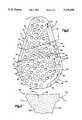
- FIG. 2is a top plan view of the glenoid component of FIG. 1;
- FIG. 3is a bottom plan view of the glenoid component of FIG. 1;
- FIG. 4is a schematic illustration of a glenoid bone prior to capping
- FIG. 5is a schematic illustration of the glenoid bone of FIG. 4 with the glenoid component of FIG. 1 in a partially inserted position;
- FIG. 6is a schematic illustration of the glenoid bone of FIG. 4 after capping with the glenoid component of FIG. 1;
- FIG. 7is a fragmentary view of a glenoid component having a modified anterior tab
- FIG. 8illustrates a glenoid component modified by the addition of a solid central keel
- FIG. 9illustrates a glenoid component modified by the addition of a central keel having a tapered opening therein;
- FIG. 10is an elevational view of a screw for use with the glenoid component of FIG. 9;
- FIG. 11is an assembly view of the parts of FIGS. 9 and 10;
- FIG. 12is a bottom plan view of a tibial component for capping a tibia in knee arthroplasty
- FIG. 13is an elevational view of the tibial component of FIG. 12;
- FIG. 14is a bottom plan view of a patellar implant in accordance with the present invention.
- FIG. 15is an elevational view of the patellar implant of FIG. 14;
- FIG. 16is an elevational view of a reinforced implant
- FIG. 17is a sectional view taken along line 17--17 of FIG. 16;
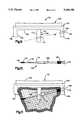
- FIG. 18is a side elevational view of another tibial tray in accordance with the present invention.
- FIG. 19is a front elevational view of the tibial tray of FIG. 18;
- FIG. 20is an end view of another bone screw in accordance with the present invention.
- FIG. 21is an elevational view of the bone screw of FIG. 20;
- FIG. 22is an end view of a third bone screw in accordance with the present invention.
- FIG. 23is an elevational view of the bone screw of FIG. 22.
- FIG. 1illustrates a glenoid component 10.
- the glenoid component 10includes a metal base 12 and a plastic insert 14.
- the metal base 12has a lower major side surface 16 for placement adjacent to the articulating surface of a glenoid bone (not shown).
- the plastic insert 14has a concave upper major side surface 18 for articulation with a humeral part of the glenohumeral joint when the glenoid component 10 caps the glenoid bone.
- the metal base 12includes a tray portion 20 with an outer periphery 30 (FIG. 2) which is the outer periphery of the glenoid component 10.
- the metal base 12has an upper peripheral portion 32, an anterior peripheral portion 34, a lower peripheral portion 36, and a posterior peripheral portion 38.
- the tray portion 20 of the glenoid component 10has an upper major side surface 40.
- the plastic insert 14is received in a cut-out 42 in the upper surface of the base tray portion 20.
- the cut-out 42is sized to snugly receive the plastic insert 14, in a known manner.
- the cut-out 42is defined by an edge surface 70 and a major side surface 72.
- the plastic insert 14has a lower side surface 74 in engagement with the surface 72 of the metal base 12, and an outer side surface 76 in engagement with the edge surface 70 of the cut-out 42 in the metal base 12.
- the metal base 12has three integral tabs projecting proximally (down as viewed in FIG. 1) from the tray portion 20. These include an anterior tab 22, an upper posterior tab 24, and a lower posterior tab 26.
- the anterior tab 22projects downwardly as viewed in FIG. 1 from the anterior peripheral portion 34 of the tray portion 20 of the metal base 12.
- the anterior tab 22extends generally normal to the tray portion 20 of the metal base 12, in a direction parallel to an axis 50 of the 10 glenoid component 10.
- the anterior tab 22has an outer side surface 44, an inner side surface 46, and a lower side surface 48 connecting the inner side surface and the outer side surface.
- a screw hole 52extends at an angle through the anterior tab 22.
- the lower posterior tab 26(FIG. 3) is generally similar to the anterior tab 22.
- the lower posterior tab 26projects downwardly as viewed in FIG. 1 from the lower peripheral portion 36 of the tray 20.
- the lower posterior tab 26has an outer surface 54, an inner surface 56, and a lower side surface 58 Joining them.
- the upper posterior tab 24has a support portion 60 (FIG. 1) having an inner side surface 62 and an outer side surface 64.
- a hook portion 66extends transversely from the support portion 60 inwardly toward the anterior tab 22 in a direction transverse to the axis 50 of the glenoid component 10.
- the hook portion 66has a relatively sharp distal end portion 68 joined by a lower side surface 70 to the outer side surface 64 of the support portion 60.
- anterior tab 22 and the posterior tabs 24 and 26can be located elsewhere on the periphery 30 of the glenoid component 10. Further, the tabs 22, 24 and 26 may have different lengths and/or configurations, so long as they serve the function of blocking lateral movement of the tray portion 20 by engagement with the outer side surface of the glenoid bone. 10 The length of the anterior tab 22 along the periphery of the glenoid component 10 is selected so as to substantially block movement of the tray portion 20 in a first direction relative to the glenoid bone, when the anterior tab 22 engages an outer side surface of the glenoid bone.
- the upper posterior tab 24 and the lower posterior tab 26are located and dimensioned so as to substantially block movement of the tray portion 20 of the glenoid component 10 relative to the glenoid bone in a second direction.
- tabsmay also be a different number of tabs provided, or even one tab extending partially or completely around the periphery 30 of the glenoid component 10.
- the lower major side surface 16 of the tray portion 20includes an axially outward web surface 80 (FIG. 3).
- the lower major side surface 16also includes a plurality of spherical surfaces 82 defining a plurality of dimples 84 in the tray portion 20.
- the dimples 84are two to three millimeters in diameter.
- the glenoid component 10is usable in capping a glenoid bone, such as the glenoid bone 100 illustrated schematically in FIGS. 4-6.
- the glenoid bone 100is funnel-shaped and has a neck portion 102 extending inwardly from the end portion 104.
- the end portion 104has an articulating surface 106 which may be cut back if desired to accommodate the thickness of the glenoid component 10.
- the glenoid bonehas an anterior outer side surface 108 and a posterior outer side surface 110.
- FIGS. 5 and 6illustrate the securing of the glenoid component 10 to the glenoid bone 100.
- the glenoid component 10is slid between the parts of the joint, from anterior to posterior, in a direction as indicated by the arrow 120.
- the posterior tabs 24 and 26 of the glenoid component 10are posterior to the glenoid bone 100, the posterior tabs are slid proximally relative to the glenoid bone 100 in a direction as indicated by the arrows 122.
- the hook portion 66 of the upper posterior tab 24, with its end portion 68,is engaged with the posterior outer side surface 110 of the glenoid bone 100 as shown in FIG. 5.
- the glenoid component 10is then pivoted about the hook portion 66, in the direction indicated by the arrow 124, from the position shown in FIG. 5 to the position shown in FIG. 6.
- the lower major side surface 16 of the glenoid component 10is adjacent to or in engagement with the articulating surface 106 of the glenoid bone 100.
- the anterior tab 22is in engagement with the anterior outer side surface 108 of the glenoid bone 100.
- the lower posterior tab 26(not shown in FIGS. 4-6) is also in engagement with the posterior outer side surface 110 of the glenoid bone 100.
- a fastenersuch as a screw 120
- the screw 120engages in the hard cortical bone on the anterior portion of the glenoid bone 100.
- the fastenermay extend across the glenoid bone 100 and terminate in the cortical bone on the posterior side of the glenoid bone. Suitable holes may be drilled in the glenoid bone 100 to receive the fastener, as necessary. It is contemplated that a glenoid component in accordance with the present invention will likely be fixed to the glenoid bone with a screw such as the screw 120. However, this may not in all cases be necessary, and so the present invention also contemplates capping with the tabs only, without a separate fastener.
- the tabs 22, 24 and 26block both lateral and axial movement of the tray portion 20 of the glenoid component 10 relative to the glenoid bone 100.
- the anterior to posterior dimension of the glenoid bone 100may be shortened, prior to capping, by resecting an anterior edge portion 112 (FIG. 4) of the glenoid bone 100, so that the glenoid component 10 snaps into position on the glenoid bone 100 and is retained snugly in position thereon. It should be understood that the steps recited above for positioning the glenoid component 10 or the glenoid bone 100 may and likely will be varied, as the surgeon moves and works the glenoid component into place on the glenoid bone, to the position shown in FIG. 5 and then the position shown in FIG. 6.
- the hook 66 on the posterior lip 24provides a pivot point for mounting of the glenoid component 10 on the glenoid bone 100.
- the hook 66also blocks axial outward movement of the glenoid component 10 from the bone 100.
- the tabs 22, 24 and 26 on the glenoid component 10engage hard cortical bone material at the outer surface of the bone 100.
- the cortical boneis less likely to wear away and loosen the grip of the tabs on the bone, than is cancellous bone.
- the fixation obtained by the present inventionis superior to that obtained by a central (intramedullary) keel which is in soft cancellous bone.
- the anterior and posterior tabs 22, 24 and 26engage the glenoid bone 100 at locations spaced from the center of the bone.
- the tabsare thus working through a longer lever arm to resist rotation of the glenoid component 10 on the bone. For this reason also, the stability obtained by the present invention is superior to that obtained by a central keel.
- component fixationis obtained at the outer edges of the bone with the present invention, no intramedullary screws are needed to affix the component. This eliminates the possibility of metal screw heads wearing on the under surface of a plastic insert, which is a known cause of component failure. It also eliminates the need for a thicker metal component to accommodate the screw fixation. Any screw fixation in the present invention is obtained laterally through the outer side surface of the glenoid bone into hard cortical bone, which is clearly superior.
- the metal base 12 of the glenoid component 10is preferably titanium or cobalt chrome two to three millimeters thick.
- the plastic insert 14is preferably polyethylene or polyetheretherketone about three millimeters thick.
- the total thickness of the glenoid componentis about five to six millimeters. This is in contrast to the normal glenoid component which is eleven millimeters thick.
- the glenoid component of the present inventioncan be made thinner because no fixation need be obtained along the tray portion, fixation rather being obtained at the side of the bone.
- FIG. 7illustrates alternative configurations for an anterior tab 22a of a glenoid component 10a.
- the anterior tab 22amay include a hook portion 126 similar to the hook portion 66 (FIG. 1) of the posterior tab 24.
- the anterior tab 22amay include a post 128 formed integrally with the anterior tab 22a, and extending inwardly from an inner side surface 130 of the tab 22a to a pointed end portion 132.
- the post 128could replace the screw 120.
- FIG. 8illustrates another alternative configuration for a glenoid component in accordance with the present invention.
- the glenoid component 134includes a metal base 136 with a plastic insert 138.
- the metal base 136has an anterior tab 140 and one or more posterior tabs 142, which may have a hook portion 144.
- a small intramedullary keel 146is provided with a pointed distal end portion 148 extending along the axis 150 of the glenoid component 134.
- the keel 146Upon movement of the glenoid component 134 into position on a glenoid bone, as illustrated in FIGS. 5 and 6, the keel 146 embeds in the intramedullary bone to further assist in stabilizing the glenoid component 134 on the glenoid bone.
- FIGS. 9-11illustrate another embodiment of the present invention in which a transcortical screw 150 assists in securing a glenoid component 152 to a glenoid bone.
- the glenoid component 152has a metal base 154 and a plastic insert 156.
- the base 154has an anterior tab 156 with a screw hole 158 extending therethrough.
- the screw hole 158is countersunk at 160.
- the base 154also has a posterior tab 162 with a hook portion 164.
- a central keel 166extends axially from a tray portion 168 of the base 154.
- the keel 166has an anterior side surface 170 and a posterior side surface 172.
- a tapered opening 174extends transversely through the keel 166 from the anterior side surface 170 to the posterior side surface 172.
- the opening 174has a standard Morse taper.
- the screw 150(FIG. 10) has a head portion 175 for engagement with the countersunk portion 160 of the screw hole 158.
- a tapered shank portion 176 of the screw 150is disposed intermediate a distal shank portion 178 and a proximal shank portion 180 of the screw 150.
- the shank portion 176has a Morse taper matching that of the opening 174 in the keel 166 of the component 152.
- the screw 150has a distal threaded portion 182 adjacent the distal end 184 of the screw 150.
- a proximal threaded portion 186is disposed on the proximal shank portion 180 adjacent the screw head 154.
- the glenoid component 152is first placed over the glenoid bone (shown schematically in FIG. 11) as described above. A through hole is drilled for the screw 150. The screw 150 is inserted through the screw hole 158 in the anterior tab 156 of the glenoid component 152. The various portions of the screw 150 are dimensioned so that, as the distal and proximal threaded portions 182 and 186 draw the screw head 175 snugly into engagement with the anterior tab 156, the tapered screw portion 176 engages in the tapered opening 174 in the keel 166. The interlocking between the screw 150 and the keel 166 further aids in stability, especially rotational stability, of the glenoid component 152 on the glenoid bone.
- proximal threaded portion 186 or the distal threaded portion 186may be omitted, and that they may have different thread pitches as desired.
- the thread portion 182is illustrated as having a finer pitch than the threaded portion 186.
- the screw 150extends at an angle ⁇ relative to the plane of the glenoid component 152.
- the angleis selected so as to provide the minimum amount of lift off and the maximum amount of rotational stability, while still maintaining anterior exposure only and cortical rather than medullary fixation. This same angle is used with the screw 120 (FIG. 6) for holding the glenoid component 10 in place on the glenoid bone 100.
- the angle ⁇is preferably about 10°.
- FIGS. 12 and 13illustrate a tibial tray 200 having an articulating surface 202 and a lower major side surface 204.
- the lower major side surface 204has a plurality of two millimeter diameter dimples or depressions 206.
- a plurality of tabs 208extend downwardly from the lower major side surface 204 of the tibial tray 200. The tabs 208 are engageable with an outer side surface of the tibia bone (not shown) to block movement of the tibial component 200 relative to the tibia.
- Fastener openings 210may be provided in the tabs 208 for optional screw fixation laterally through cortical bone of the tibia.
- the number, dimensions, and placement of the tabs 208may be selected to give best securing of the tibial tray 200 to the tibia.
- bone cementmay be used if desired by the surgeon.
- the texturing of the lower side surfaces of the illustrated componentsis useful in this regard.
- Bone cementis applied between the end surface of the bone to be capped and the lower major side surface of the component.
- the bone cementflows mainly into the dimples or impressions on the lower side surface of the component, and also may form a thin layer on the web surface of the component.
- the bone cementwhen applied between the articulating surface 106 (FIG. 6) of the glenoid bone 100 and the lower major side surface 16 of the glenoid component 10, would flow into the dimples 84, and possibly lie on the web surface 80.
- any cracks which would form in the bone cementwould tend to propagate only to or through one dimple 84, and then stop. This can potentially avoid cracks spreading through the entire extent of the layer of bone cement and thus destroying the efficacy of the cement.
- a further example of an arthroplasty component in accordance with the present inventionis the patellar implant 300 illustrated in FIGS. 14 and 15.
- the implant 300has a tray portion 302 with a web surface 304 surrounding a plurality of dimples 306. Three posts 308 project from the tray portion 306.
- the implant 300is affixed to a patella, the majority of the bone cement applied between the surface of the patella and the tray portion 302 flows into the dimples 306 rather than lying on the web surface 304.
- any cracks which might develop in the bone cementare limited to the individual packets of bone cement within the dimples 306.
- the present inventionalso relates to a method of capping a bone in arthroplasty such as shoulder arthroplasty.
- the jointis first exposed anteriorly so that there is two to three centimeters of space at the anterior side of the joint, between the glenoid bone 100 and the humeral head (not shown).
- the glenoid component 10(FIGS. 5 and 6) is then inserted between the glenoid bone 100 and the humeral head in a posterior direction, as indicated by the arrow 120, with the posterior lips 24 and 26 of the glenoid component 10 being inserted first.
- the glenoid component 10is inserted until the posterior lips 24 and 26 of the glenoid component are posterior to the glenoid bone 100.
- the posterior lips 24 and 26 of the glenoid component 10are slid proximally down onto the outer side surface 110 of the glenoid bone 100.
- the hook 66 on the posterior lip 24engages the outer side surface 110 of the glenoid bone 100 and may make a small impression therein.
- the glenoid component 10is then pivoted, in the direction indicated by the arrow 124, into the capped position shown in FIG. 6.
- the anterior lip 22snaps around the glenoid bone 100 to engage the anterior outer side surface 108 of the glenoid bone 100 at a location spaced from the posterior lips 24 and 26.
- the lower major side surface 16 of the tray portion 20is adjacent to or engaged with the articulating surface 106 of the glenoid bone 100.
- glenoid bone 100is too large in diameter to fit between the anterior and posterior lips of the glenoid component 10, a small anterior portion of the glenoid bone may be removed as shown at 144, prior to capping with the anterior lip 22.
- a very snug fit between the glenoid component 10 and the glenoid bone 100This can be achieved by sizing the glenoid bone 100 and the glenoid component 10 so that the surgeon must exert some force to affix the glenoid component to the glenoid bone.
- a fastenersuch as a screw 120 through the screw opening 52 in the anterior lip 22.
- the screw 120seats in the hard cortical bone material at the side of the glenoid bone.
- the anterior and posterior tabs and the screwblock movement of the tray portion 20 and the entire glenoid component 10 relative to the bone 100. Because of the secure fixation of the glenoid component 10, a central keel is not needed.
- a low coefficient of frictionis needed at the joint (articulating) surface, because it is bearing on metal.
- plasticis chosen for the upper portion or insert of the implant.
- Strength and rigidityare needed for the base, in contact with and securing the articulating surface to the bone.
- metalis chosen for the base.
- the tibial tray 200(FIGS. 12 and 13), unlike the glenoid component 10 illustrated in FIGS. 1-5, is made of only one piece rather than a metal base and a plastic insert.
- plastics which are best suited to function as an articulating surfaceare not well suited to function as a base.
- Polyethylenefor example, which is suitable as an articulating surface, is too soft and flexible and is not rigid enough over time to present a stable surface for bone to bond to. Also, such plastics can fail when screwed into bone.
- all-plastic insertsare always cemented to the bone.
- bone cementdoes not provide a stable long-term method of fixation.
- bone ingrowth materialcan not be used. Bone ingrowth material such as hydroxyapatite (HA) or tricalcium phosphate (TCP) will not stick to known bone implant polymers such as polyethylene. Thus, it is not possible to augment the body's natural bone growth function at the junction between the implant and the bone. Accordingly, the all-plastic (one-material) implants available today are deficient in all these regards.
- PEEKpolyetheretherketone
- Unreinforced PEEKhas a coefficient of friction which is acceptably low for a joint surface, that is, a coefficient of friction about twice that of polyethylene. Thus, unreinforced PEEK is suitable for articulation.
- bone ingrowth materialcan be bonded to PEEK and will stick.
- an implant of plasticspecifically, PEEK
- bond a bone ingrowth surfaceto the lower major side surface (and outer side surfaces also) of the implant. This will make the implant cementless, as the bone ingrowth material promotes rapid bone ingrowth and thus substitutes for the cement.
- the implantcan be made entirely of PEEK reinforced as desired.
- the implantcan be made of another polymer such as polysulfone or PAEK (polyaryletherketone), reinforced with fibers to form a composite. Suitable fibers include carbon fibers and aramid (Kevlar®) fibers.
- the implantcan also be a base made from PEEK preferably reinforced with an insert made from another material such as polyethylene.
- the bone ingrowth materialcan be bonded on as a layer 50-100 microns thick, or in the form of a mesh or beaded surface with 150-400 micron bead porosity.
- Known techniques for bonding bone ingrowth materialsuch as plasma spraying, can be used, perhaps at a low temperature.
- FIGS. 16 and 17illustrate an arthroplasty component 350 for capping a bone such as a glenoid bone or a tibia.
- the component 350can be implanted in the manner described above.
- the component 350has a tray portion 352 with an articulating surface 354 and has two tab portions 356 and 358 for fixation to cortical bone material.
- the component 350is made of a body 360 of PEEK reinforced with fibers 362.
- the fibers 362are densest at the proximal portion 364 of the component 350.
- the fibers 362are less dense at a central portion 366 of the component 350.
- the portion 368 of the component 350is suitable to provide the articulating surface 354.
- the component 350has a layer of bone ingrowth material 370 bonded to it, in the manner and for the purposes discussed above.
- FIGS. 18 and 19illustrate another tibial tray in accordance with the present invention.
- the tibial tray 372includes a plastic insert 374 fixed to a metal base 376.
- the insert 374has a hollowed out articulating surface 378.
- the basehas a projecting tab 380 which extends along the outer side surface of a tibia (shown in phantom).
- a screw hole 382may be formed in the tab 380 to receive therethrough a screw (not show) for fixation to the tibia.
- Additional tabs like the tab 380may be provided, having a fixed pin attached thereto (or formed therewith), a screw hole, or no additional attachment features.
- FIGS. 20-23illustrate other fixation screws for use in implant fixation in accordance with the present invention.
- the screw 384(FIGS. 20-21) has a head 386 with a driver slot 388.
- a large diameter shank portion 390extends from the head 386.
- a thread convolution 392is formed on the large diameter shank portion 390.
- a tapered portion 394 having a truncated conical outer surface 396extends from the large diameter shank portion 390.
- the tapered portion 394is smaller in diameter than the thread convolution 392.
- a small diameter shank portion 398extends from the tapered portion 394.
- a thread convolution 400is formed on the small diameter shank portion 398.
- the tapered portion 394is engageable with an opening in a keel in an implant (not shown) as in FIGS. 9-11.
- the screw 402(FIGS. 22-23) does not have a radially enlarged head but instead has a hex driver opening slot 404 in the proximal end surface 406 of a constant diameter shank portion 408.
- a thread convolution 410is formed on the constant diameter shank portion 408.
- a tapered portion 412extends from the large diameter shank portion 390 and terminates in a pointed distal end 412. The tapered portion 412 is smaller in diameter than the thread convolution 410.
- the tapered portion 412is engageable with an opening in a keel in an implant (not shown) as in FIGS. 9-11.
Landscapes
- Health & Medical Sciences (AREA)
- Orthopedic Medicine & Surgery (AREA)
- Engineering & Computer Science (AREA)
- Life Sciences & Earth Sciences (AREA)
- Public Health (AREA)
- Veterinary Medicine (AREA)
- Animal Behavior & Ethology (AREA)
- General Health & Medical Sciences (AREA)
- Oral & Maxillofacial Surgery (AREA)
- Transplantation (AREA)
- Biomedical Technology (AREA)
- Heart & Thoracic Surgery (AREA)
- Chemical & Material Sciences (AREA)
- Vascular Medicine (AREA)
- Cardiology (AREA)
- Epidemiology (AREA)
- Materials Engineering (AREA)
- Dermatology (AREA)
- Medicinal Chemistry (AREA)
- Composite Materials (AREA)
- Surgery (AREA)
- Physical Education & Sports Medicine (AREA)
- Neurology (AREA)
- Nuclear Medicine, Radiotherapy & Molecular Imaging (AREA)
- Medical Informatics (AREA)
- Molecular Biology (AREA)
- Manufacturing & Machinery (AREA)
- Prostheses (AREA)
Abstract
Description
Claims (43)
Priority Applications (2)
| Application Number | Priority Date | Filing Date | Title |
|---|---|---|---|
| US07/926,481US5344458A (en) | 1992-08-06 | 1992-08-06 | Arthroplasty component |
| US08/234,974US5549683A (en) | 1992-08-06 | 1994-04-28 | Anthroplasty component |
Applications Claiming Priority (1)
| Application Number | Priority Date | Filing Date | Title |
|---|---|---|---|
| US07/926,481US5344458A (en) | 1992-08-06 | 1992-08-06 | Arthroplasty component |
Related Parent Applications (1)
| Application Number | Title | Priority Date | Filing Date |
|---|---|---|---|
| US07/799,560Continuation-In-PartUS5514143A (en) | 1991-11-27 | 1991-11-27 | Apparatus and method for use during surgery |
Related Child Applications (1)
| Application Number | Title | Priority Date | Filing Date |
|---|---|---|---|
| US08/234,974DivisionUS5549683A (en) | 1992-08-06 | 1994-04-28 | Anthroplasty component |
Publications (1)
| Publication Number | Publication Date |
|---|---|
| US5344458Atrue US5344458A (en) | 1994-09-06 |
Family
ID=25453266
Family Applications (2)
| Application Number | Title | Priority Date | Filing Date |
|---|---|---|---|
| US07/926,481Expired - LifetimeUS5344458A (en) | 1992-08-06 | 1992-08-06 | Arthroplasty component |
| US08/234,974Expired - LifetimeUS5549683A (en) | 1992-08-06 | 1994-04-28 | Anthroplasty component |
Family Applications After (1)
| Application Number | Title | Priority Date | Filing Date |
|---|---|---|---|
| US08/234,974Expired - LifetimeUS5549683A (en) | 1992-08-06 | 1994-04-28 | Anthroplasty component |
Country Status (1)
| Country | Link |
|---|---|
| US (2) | US5344458A (en) |
Cited By (90)
| Publication number | Priority date | Publication date | Assignee | Title |
|---|---|---|---|---|
| US5507827A (en)* | 1993-06-08 | 1996-04-16 | Eska Medical Gmbh & Co. | Pelvis part endoprosthesis |
| EP0800802A3 (en)* | 1996-04-10 | 1997-12-17 | Sulzer Orthopädie AG | Metallic implant having a surface and method of producing the surface |
| FR2776506A1 (en)* | 1998-03-25 | 1999-10-01 | Depuy France | Shoulder prosthesis glenoid member and ancillary components |
| US5965006A (en)* | 1996-04-10 | 1999-10-12 | Sulzer Orthopaedie Ag | Method for producing a metal surface |
| WO1999056673A1 (en)* | 1998-05-06 | 1999-11-11 | Malawer Martin M | Acetabulum spacing device |
| ES2138910A1 (en)* | 1997-09-18 | 2000-01-16 | Ayala Andrade Juan De Dios | Locked tibial component for total knee prosthesis and guide for the positioning thereof. |
| EP1043001A3 (en)* | 1999-04-07 | 2000-10-18 | Depuy Orthopaedics, Inc. | Collarless shoulder arthroplasty prosthesis |
| US6312470B1 (en) | 1998-05-06 | 2001-11-06 | Martin M. Malawer | Acetabulum spacing device |
| US6620199B2 (en) | 2001-07-13 | 2003-09-16 | Ronald P. Grelsamer | Device for reinforcing bone in partial knee replacement surgery |
| US6702821B2 (en) | 2000-01-14 | 2004-03-09 | The Bonutti 2003 Trust A | Instrumentation for minimally invasive joint replacement and methods for using same |
| US20040083005A1 (en)* | 1998-12-22 | 2004-04-29 | Magnus Jacobsson | Method of anchoring a prosthesis structure |
| US20040107000A1 (en)* | 2000-08-28 | 2004-06-03 | Felt Jeffrey C. | Method and system for mammalian joint resurfacing |
| US20040220670A1 (en)* | 2003-02-12 | 2004-11-04 | Sdgi Holdings, Inc. | Articular disc prosthesis and method for treating spondylolisthesis |
| US20050085917A1 (en)* | 1999-07-02 | 2005-04-21 | Thierry Marnay | Intervertebral implant |
| EP1323395A3 (en)* | 2001-12-31 | 2005-08-17 | Depuy Orthopaedics, Inc. | Augmented glenoid component having an interrupted surface |
| US20050251261A1 (en)* | 2004-05-05 | 2005-11-10 | Sdgi Holdings, Inc. | Artificial intervertebral disc for lateral insertion |
| US20060058809A1 (en)* | 2004-06-03 | 2006-03-16 | Zink Robert W | Method and apparatus for preparing a glenoid surface |
| US20060195194A1 (en)* | 2005-02-25 | 2006-08-31 | Gunther Stephen B | Shoulder implant for glenoid replacement and methods of use thereof |
| US7104996B2 (en) | 2000-01-14 | 2006-09-12 | Marctec. Llc | Method of performing surgery |
| US20060282169A1 (en)* | 2004-12-17 | 2006-12-14 | Felt Jeffrey C | System and method for upper extremity joint arthroplasty |
| US20070239276A1 (en)* | 2006-04-07 | 2007-10-11 | Sdgi Holdings, Inc. | Artificial disc implants and associated methods and instrumentation |
| US7297163B2 (en) | 1998-03-17 | 2007-11-20 | Acumed Llc | Shoulder prosthesis |
| US20080021564A1 (en)* | 2006-07-20 | 2008-01-24 | Gunther Stephen B | Humeral head resurfacing implant and methods of use thereof |
| US20080215059A1 (en)* | 2000-03-17 | 2008-09-04 | Kinamed, Inc. | Marking template for installing a custom replacement device for resurfacing a femur and associated installation method |
| US20080228276A1 (en)* | 2007-03-14 | 2008-09-18 | Warsaw Orthopedic, Inc. | Intervertebral Prosthesis, Instruments, and Methods of Implanting |
| US7488324B1 (en) | 2003-12-08 | 2009-02-10 | Biomet Manufacturing Corporation | Femoral guide for implanting a femoral knee prosthesis |
| US7510557B1 (en) | 2000-01-14 | 2009-03-31 | Bonutti Research Inc. | Cutting guide |
| US20090182432A1 (en)* | 1999-06-04 | 2009-07-16 | Warsaw Orthopedic, Inc. | Artificial disc implant |
| US7575600B2 (en) | 2004-09-29 | 2009-08-18 | Kyphon Sarl | Artificial vertebral disk replacement implant with translating articulation contact surface and method |
| US7670377B2 (en) | 2003-11-21 | 2010-03-02 | Kyphon Sarl | Laterally insertable artifical vertebral disk replacement implant with curved spacer |
| US7695520B2 (en) | 2006-05-31 | 2010-04-13 | Biomet Manufacturing Corp. | Prosthesis and implementation system |
| US7695479B1 (en) | 2005-04-12 | 2010-04-13 | Biomet Manufacturing Corp. | Femoral sizer |
| US7708741B1 (en) | 2001-08-28 | 2010-05-04 | Marctec, Llc | Method of preparing bones for knee replacement surgery |
| US7780672B2 (en) | 2006-02-27 | 2010-08-24 | Biomet Manufacturing Corp. | Femoral adjustment device and associated method |
| US7789885B2 (en) | 2003-01-15 | 2010-09-07 | Biomet Manufacturing Corp. | Instrumentation for knee resection |
| US7799084B2 (en) | 2002-10-23 | 2010-09-21 | Mako Surgical Corp. | Modular femoral component for a total knee joint replacement for minimally invasive implantation |
| US7803162B2 (en) | 2003-07-21 | 2010-09-28 | Spine Solutions, Inc. | Instruments and method for inserting an intervertebral implant |
| US20100249938A1 (en)* | 2005-02-25 | 2010-09-30 | Gunther Stephen B | Methods and devices for less invasive glenoid replacement |
| US7837690B2 (en) | 2003-01-15 | 2010-11-23 | Biomet Manufacturing Corp. | Method and apparatus for less invasive knee resection |
| EP1703867A4 (en)* | 2004-01-12 | 2011-01-19 | Depuy Products Inc | Systems and methods for compartmental replacement in a knee |
| US7887542B2 (en) | 2003-01-15 | 2011-02-15 | Biomet Manufacturing Corp. | Method and apparatus for less invasive knee resection |
| US8038718B2 (en) | 2005-03-09 | 2011-10-18 | Vertebral Technologies, Inc. | Multi-composite disc prosthesis |
| US8070752B2 (en) | 2006-02-27 | 2011-12-06 | Biomet Manufacturing Corp. | Patient specific alignment guide and inter-operative adjustment |
| US8265949B2 (en) | 2007-09-27 | 2012-09-11 | Depuy Products, Inc. | Customized patient surgical plan |
| US20120259312A1 (en)* | 2011-04-10 | 2012-10-11 | The Cleveland Clinic Foundation | Methods and devices for bone preparation |
| US8337500B2 (en) | 2006-07-31 | 2012-12-25 | Synthes Usa, Llc | Drilling/milling guide and keel cut preparation system |
| US8343159B2 (en) | 2007-09-30 | 2013-01-01 | Depuy Products, Inc. | Orthopaedic bone saw and method of use thereof |
| US8357111B2 (en) | 2007-09-30 | 2013-01-22 | Depuy Products, Inc. | Method and system for designing patient-specific orthopaedic surgical instruments |
| US8425603B2 (en) | 2008-12-22 | 2013-04-23 | Synthes Usa, Llc | Orthopedic implant with flexible keel |
| US20130103160A1 (en)* | 2010-04-22 | 2013-04-25 | Depuy (Ireland) | Composite trial prosthesis |
| US8551100B2 (en) | 2003-01-15 | 2013-10-08 | Biomet Manufacturing, Llc | Instrumentation for knee resection |
| US20140257504A1 (en)* | 2013-03-11 | 2014-09-11 | Howmedica Osteonics Corp. | Implant system with pe insert and two tray options |
| US8968412B2 (en) | 2011-06-30 | 2015-03-03 | Depuy (Ireland) | Trialing system for a knee prosthesis and method of use |
| US8998990B2 (en) | 2006-07-24 | 2015-04-07 | DePuy Synthes Products, LLC | Intervertebral implant with keel |
| US9510953B2 (en) | 2012-03-16 | 2016-12-06 | Vertebral Technologies, Inc. | Modular segmented disc nucleus implant |
| US9700329B2 (en) | 2006-02-27 | 2017-07-11 | Biomet Manufacturing, Llc | Patient-specific orthopedic instruments |
| US9737414B2 (en) | 2006-11-21 | 2017-08-22 | Vertebral Technologies, Inc. | Methods and apparatus for minimally invasive modular interbody fusion devices |
| US9743935B2 (en) | 2011-03-07 | 2017-08-29 | Biomet Manufacturing, Llc | Patient-specific femoral version guide |
| US9757244B2 (en)* | 2015-01-12 | 2017-09-12 | Wright Medical Technology, Inc. | Targeted screw for talar dome fixation |
| US9795399B2 (en) | 2006-06-09 | 2017-10-24 | Biomet Manufacturing, Llc | Patient-specific knee alignment guide and associated method |
| US9861491B2 (en) | 2014-04-30 | 2018-01-09 | Depuy Ireland Unlimited Company | Tibial trial system for a knee prosthesis |
| US9913734B2 (en) | 2006-02-27 | 2018-03-13 | Biomet Manufacturing, Llc | Patient-specific acetabular alignment guides |
| US9968376B2 (en) | 2010-11-29 | 2018-05-15 | Biomet Manufacturing, Llc | Patient-specific orthopedic instruments |
| US10159498B2 (en) | 2008-04-16 | 2018-12-25 | Biomet Manufacturing, Llc | Method and apparatus for manufacturing an implant |
| US10182831B2 (en) | 2003-04-28 | 2019-01-22 | Centinel Spine Llc | Instruments and method for preparing an intervertebral space for receiving an artificial disc implant |
| US10195056B2 (en) | 2015-10-19 | 2019-02-05 | Depuy Ireland Unlimited Company | Method for preparing a patient's tibia to receive an implant |
| US10206695B2 (en) | 2006-02-27 | 2019-02-19 | Biomet Manufacturing, Llc | Femoral acetabular impingement guide |
| EP3334384A4 (en)* | 2015-08-14 | 2019-04-10 | Gerhard E. Maale | PROSTHESIS OF GLENOID PIT |
| US10278711B2 (en) | 2006-02-27 | 2019-05-07 | Biomet Manufacturing, Llc | Patient-specific femoral guide |
| US10390845B2 (en) | 2006-02-27 | 2019-08-27 | Biomet Manufacturing, Llc | Patient-specific shoulder guide |
| US10426492B2 (en) | 2006-02-27 | 2019-10-01 | Biomet Manufacturing, Llc | Patient specific alignment guide with cutting surface and laser indicator |
| US10492926B1 (en) | 2014-09-04 | 2019-12-03 | Shoulder Innovations, Inc. | Alignment guide for humeral or femoral stem replacement prostheses |
| US10507029B2 (en) | 2006-02-27 | 2019-12-17 | Biomet Manufacturing, Llc | Patient-specific acetabular guides and associated instruments |
| US10537445B2 (en) | 2015-10-19 | 2020-01-21 | Depuy Ireland Unlimited Company | Surgical instruments for preparing a patient's tibia to receive an implant |
| US10603179B2 (en) | 2006-02-27 | 2020-03-31 | Biomet Manufacturing, Llc | Patient-specific augments |
| US10722310B2 (en) | 2017-03-13 | 2020-07-28 | Zimmer Biomet CMF and Thoracic, LLC | Virtual surgery planning system and method |
| US10743937B2 (en) | 2006-02-27 | 2020-08-18 | Biomet Manufacturing, Llc | Backup surgical instrument system and method |
| US11051829B2 (en) | 2018-06-26 | 2021-07-06 | DePuy Synthes Products, Inc. | Customized patient-specific orthopaedic surgical instrument |
| US11065125B2 (en) | 2017-04-14 | 2021-07-20 | Shoulder Innovations, Inc. | Total shoulder prosthesis having inset glenoid implant convertible from anatomic to reverse |
| CN114449981A (en)* | 2019-10-10 | 2022-05-06 | 国立大学法人爱媛大学 | Artificial knee joint, beam member, insert member, and base plate used for the artificial knee joint |
| US11344423B1 (en) | 2009-03-05 | 2022-05-31 | Howmedica Osteonics Corp. | Glenoid implant anchor post |
| US11534313B2 (en) | 2006-02-27 | 2022-12-27 | Biomet Manufacturing, Llc | Patient-specific pre-operative planning |
| US11554019B2 (en) | 2007-04-17 | 2023-01-17 | Biomet Manufacturing, Llc | Method and apparatus for manufacturing an implant |
| USD977643S1 (en) | 2019-03-12 | 2023-02-07 | Shoulder Innovations, Inc. | Humeral stem implant |
| US20230090753A1 (en) | 2019-03-11 | 2023-03-23 | Shoulder Innovations, Inc. | Total reverse shoulder systems and methods |
| US11890202B2 (en) | 2007-06-20 | 2024-02-06 | 3Spine, Inc. | Spinal osteotomy |
| US11957595B2 (en) | 2005-02-25 | 2024-04-16 | Shoulder Innovations, Inc. | Methods and devices for less invasive glenoid replacement |
| US11992414B2 (en)* | 2018-10-29 | 2024-05-28 | Arthrosurface Incorporated | Articular surface implants with dimples |
| US12138172B2 (en) | 2018-04-30 | 2024-11-12 | Shoulder Innovations, Inc. | Inset/onlay glenoid, porous coated convertible glenoid, and humeral heads with textured undersides |
| US12409046B2 (en) | 2022-04-12 | 2025-09-09 | 3Spine, Inc. | Total spinal joint systems with motion moderators |
Families Citing this family (32)
| Publication number | Priority date | Publication date | Assignee | Title |
|---|---|---|---|---|
| US6695848B2 (en) | 1994-09-02 | 2004-02-24 | Hudson Surgical Design, Inc. | Methods for femoral and tibial resection |
| US8603095B2 (en) | 1994-09-02 | 2013-12-10 | Puget Bio Ventures LLC | Apparatuses for femoral and tibial resection |
| US6007538A (en) | 1997-07-25 | 1999-12-28 | Duke University | Sternal closure device |
| US6827742B2 (en)* | 1998-05-14 | 2004-12-07 | Daniel E. E. Hayes, Jr. | Bimetal acetabular component construct for hip joint prosthesis |
| US6261322B1 (en) | 1998-05-14 | 2001-07-17 | Hayes Medical, Inc. | Implant with composite coating |
| US6080196A (en)* | 1999-03-04 | 2000-06-27 | Bertin; Kim C. | Patella height gauge and method of locating a patella using same |
| US6423067B1 (en) | 1999-04-29 | 2002-07-23 | Theken Surgical Llc | Nonlinear lag screw with captive driving device |
| US6770078B2 (en) | 2000-01-14 | 2004-08-03 | Peter M. Bonutti | Movable knee implant and methods therefor |
| EP1331904B1 (en)* | 2000-07-20 | 2005-06-01 | Hayes Medical Inc. | Bimetal tibial component construct for knee joint prosthesis |
| US8062377B2 (en) | 2001-03-05 | 2011-11-22 | Hudson Surgical Design, Inc. | Methods and apparatus for knee arthroplasty |
| GB0122779D0 (en)* | 2001-09-21 | 2001-11-14 | Ryd Leif | An osteoprosthesis component |
| US7922772B2 (en)* | 2002-05-24 | 2011-04-12 | Zimmer, Inc. | Implants and related methods and apparatus for securing an implant on an articulating surface of an orthopedic joint |
| US7771483B2 (en)* | 2003-12-30 | 2010-08-10 | Zimmer, Inc. | Tibial condylar hemiplasty implants, anchor assemblies, and related methods |
| US20040006393A1 (en)* | 2002-07-03 | 2004-01-08 | Brian Burkinshaw | Implantable prosthetic knee for lateral compartment |
| US7001389B1 (en) | 2002-07-05 | 2006-02-21 | Navarro Richard R | Fixed and variable locking fixation assembly |
| US7867236B2 (en)* | 2003-12-30 | 2011-01-11 | Zimmer, Inc. | Instruments and methods for preparing a joint articulation surface for an implant |
| US9814539B2 (en) | 2004-01-14 | 2017-11-14 | Puget Bioventures Llc | Methods and apparatus for conformable prosthetic implants |
| US8114083B2 (en) | 2004-01-14 | 2012-02-14 | Hudson Surgical Design, Inc. | Methods and apparatus for improved drilling and milling tools for resection |
| US20060030854A1 (en) | 2004-02-02 | 2006-02-09 | Haines Timothy G | Methods and apparatus for wireplasty bone resection |
| US8852195B2 (en) | 2004-07-09 | 2014-10-07 | Zimmer, Inc. | Guide templates for surgical implants and related methods |
| DK1848473T3 (en)* | 2005-02-07 | 2013-09-02 | Hanuman Llc | Plasma concentrations device |
| US7694828B2 (en) | 2005-04-27 | 2010-04-13 | Biomet Manufacturing Corp. | Method and apparatus for producing autologous clotting components |
| US7572293B2 (en)* | 2005-06-30 | 2009-08-11 | Depuy Products, Inc. | Tibial insert and associated surgical method |
| GB2431354A (en)* | 2005-10-24 | 2007-04-25 | Benoist Girard Sas | A prosthetic glenoid component with soft bearing surface |
| US8540778B2 (en)* | 2006-06-22 | 2013-09-24 | DePuy Synthes Products, LLC | Tibial insert having multiple keels |
| US8114165B2 (en)* | 2006-06-22 | 2012-02-14 | Depuy Products, Inc. | Tibial insert and method for implanting the same |
| US8764839B2 (en)* | 2006-06-22 | 2014-07-01 | DePuy Synthes Products, LLC | Tibial insert having a keel including a bore formed therein |
| US8163027B2 (en)* | 2006-06-22 | 2012-04-24 | Depuy Products, Inc. | Tibial insert having a reinforced keel |
| US7896923B2 (en)* | 2006-11-30 | 2011-03-01 | Biomet Manufacturing Corp. | Arthroscopic unicompartmental knee implantation system and related method |
| US9095444B2 (en) | 2009-07-24 | 2015-08-04 | Warsaw Orthopedic, Inc. | Implant with an interference fit fastener |
| WO2011112710A1 (en)* | 2010-03-09 | 2011-09-15 | Rolston Lindsey R | Device for unicompartmental knee arthroplasty |
| US9550028B2 (en) | 2014-05-06 | 2017-01-24 | Biomet Biologics, LLC. | Single step desiccating bead-in-syringe concentrating device |
Citations (16)
| Publication number | Priority date | Publication date | Assignee | Title |
|---|---|---|---|---|
| FR2266492A1 (en)* | 1974-04-08 | 1975-10-31 | Garonne Ets Auriol & Cie | Artificial knee joint - has plates removable from tibia base sections and supporting femoral assembly |
| US4038704A (en)* | 1975-06-11 | 1977-08-02 | Downs Surgical Limited | Elbow prosthesis |
| SU719625A1 (en)* | 1978-04-26 | 1980-03-05 | Центральный Ордена Трудового Красного Знамени Научно-Исследовательский Институт Травматологии И Ортопедии Им. Н.Н.Приорова | Artificial knee joint |
| SU757159A1 (en)* | 1978-05-11 | 1980-08-23 | Bori A Asin | Knee-joint endoprosthesis |
| US4355429A (en)* | 1979-01-26 | 1982-10-26 | Osteo Ag | Slide prosthesis for the knee joint |
| DE3429157A1 (en)* | 1984-08-08 | 1986-02-20 | Harry Prof. Dr.med. 1000 Berlin Buse | Tibial plateau implant for cementless implantation |
| US4662887A (en)* | 1984-06-15 | 1987-05-05 | Imperial Chemical Industries | Prosthetic devices |
| US4769040A (en)* | 1986-11-18 | 1988-09-06 | Queen's University At Kingston | Tibial prosthesis |
| US4778469A (en)* | 1986-11-04 | 1988-10-18 | Pfizer Hospital Products Group Inc. | Method of forming tissue ingrowth surface on surgical implants |
| FR2625096A1 (en)* | 1987-12-29 | 1989-06-30 | Hummer Jacques | Cementless total knee prosthesis |
| US4865607A (en)* | 1985-10-02 | 1989-09-12 | Ulrich Witzel | Tibial plate for a knee-joint endoprosthesis |
| US4892552A (en)* | 1984-03-30 | 1990-01-09 | Ainsworth Robert D | Orthopedic device |
| US4919671A (en)* | 1987-05-15 | 1990-04-24 | Sulzer Brothers Limited | Metal anchoring part for a knee joint endoprosthesis |
| US4963153A (en)* | 1987-06-30 | 1990-10-16 | Sulzer Brothers Limited | Metal tibial anchoring part for a partial knee joint prosthesis |
| US4963152A (en)* | 1986-10-27 | 1990-10-16 | Intermedics Orthopedics, Inc. | Asymmetric prosthetic tibial component |
| US5064439A (en)* | 1987-01-20 | 1991-11-12 | Richards Medical Company | Orthopedic device of biocompatible polymer with oriented fiber reinforcement |
Family Cites Families (9)
| Publication number | Priority date | Publication date | Assignee | Title |
|---|---|---|---|---|
| FR2416683A1 (en)* | 1978-02-10 | 1979-09-07 | Judet Robert | IMPROVEMENTS TO OSTEO-SYNTHESIS DEVICES |
| ZA80327B (en)* | 1979-08-23 | 1981-09-30 | U Mennen | Internal fixation device for bone fractures |
| US4463753A (en)* | 1980-01-04 | 1984-08-07 | Gustilo Ramon B | Compression bone screw |
| CH663893A5 (en)* | 1984-07-05 | 1988-01-29 | Sulzer Ag | Cement-less hip socket prosthesis - has horizontal knife edges protruding from polar area and extending downwards |
| US4640271A (en)* | 1985-11-07 | 1987-02-03 | Zimmer, Inc. | Bone screw |
| FR2595241B1 (en)* | 1986-03-07 | 1992-08-21 | Erato | HIP PROSTHESIS |
| IT1237496B (en)* | 1989-10-26 | 1993-06-08 | Giuseppe Vrespa | SCREW DEVICE FOR ANCHORING BONE PROSTHESES, METHOD FOR THE APPLICATION OF SUCH DEVICE AND RELATED EQUIPMENT |
| FR2660546B1 (en)* | 1990-04-06 | 1994-06-03 | Setiey Louis | COTYLOUIDIAN RECONSTRUCTION MODULE. |
| US5180383A (en)* | 1991-10-09 | 1993-01-19 | Haydon Frank A | Method and device for attaching artificial joint implants to the ends of bones |
- 1992
- 1992-08-06USUS07/926,481patent/US5344458A/ennot_activeExpired - Lifetime
- 1994
- 1994-04-28USUS08/234,974patent/US5549683A/ennot_activeExpired - Lifetime
Patent Citations (16)
| Publication number | Priority date | Publication date | Assignee | Title |
|---|---|---|---|---|
| FR2266492A1 (en)* | 1974-04-08 | 1975-10-31 | Garonne Ets Auriol & Cie | Artificial knee joint - has plates removable from tibia base sections and supporting femoral assembly |
| US4038704A (en)* | 1975-06-11 | 1977-08-02 | Downs Surgical Limited | Elbow prosthesis |
| SU719625A1 (en)* | 1978-04-26 | 1980-03-05 | Центральный Ордена Трудового Красного Знамени Научно-Исследовательский Институт Травматологии И Ортопедии Им. Н.Н.Приорова | Artificial knee joint |
| SU757159A1 (en)* | 1978-05-11 | 1980-08-23 | Bori A Asin | Knee-joint endoprosthesis |
| US4355429A (en)* | 1979-01-26 | 1982-10-26 | Osteo Ag | Slide prosthesis for the knee joint |
| US4892552A (en)* | 1984-03-30 | 1990-01-09 | Ainsworth Robert D | Orthopedic device |
| US4662887A (en)* | 1984-06-15 | 1987-05-05 | Imperial Chemical Industries | Prosthetic devices |
| DE3429157A1 (en)* | 1984-08-08 | 1986-02-20 | Harry Prof. Dr.med. 1000 Berlin Buse | Tibial plateau implant for cementless implantation |
| US4865607A (en)* | 1985-10-02 | 1989-09-12 | Ulrich Witzel | Tibial plate for a knee-joint endoprosthesis |
| US4963152A (en)* | 1986-10-27 | 1990-10-16 | Intermedics Orthopedics, Inc. | Asymmetric prosthetic tibial component |
| US4778469A (en)* | 1986-11-04 | 1988-10-18 | Pfizer Hospital Products Group Inc. | Method of forming tissue ingrowth surface on surgical implants |
| US4769040A (en)* | 1986-11-18 | 1988-09-06 | Queen's University At Kingston | Tibial prosthesis |
| US5064439A (en)* | 1987-01-20 | 1991-11-12 | Richards Medical Company | Orthopedic device of biocompatible polymer with oriented fiber reinforcement |
| US4919671A (en)* | 1987-05-15 | 1990-04-24 | Sulzer Brothers Limited | Metal anchoring part for a knee joint endoprosthesis |
| US4963153A (en)* | 1987-06-30 | 1990-10-16 | Sulzer Brothers Limited | Metal tibial anchoring part for a partial knee joint prosthesis |
| FR2625096A1 (en)* | 1987-12-29 | 1989-06-30 | Hummer Jacques | Cementless total knee prosthesis |
Non-Patent Citations (2)
| Title |
|---|
| Article entitled "Ketone-based Resins", author unknown, Modern Plastics, pp. 21-11, Mid-Oct., 1991. |
| Article entitled Ketone based Resins , author unknown, Modern Plastics, pp. 21 11, Mid Oct., 1991.* |
Cited By (218)
| Publication number | Priority date | Publication date | Assignee | Title |
|---|---|---|---|---|
| US5507827A (en)* | 1993-06-08 | 1996-04-16 | Eska Medical Gmbh & Co. | Pelvis part endoprosthesis |
| EP0800802A3 (en)* | 1996-04-10 | 1997-12-17 | Sulzer Orthopädie AG | Metallic implant having a surface and method of producing the surface |
| US5965006A (en)* | 1996-04-10 | 1999-10-12 | Sulzer Orthopaedie Ag | Method for producing a metal surface |
| US6200346B1 (en) | 1996-04-10 | 2001-03-13 | Sulzer Orthopaedie Ag | Metal implant with anchoring surface |
| ES2138910A1 (en)* | 1997-09-18 | 2000-01-16 | Ayala Andrade Juan De Dios | Locked tibial component for total knee prosthesis and guide for the positioning thereof. |
| US7297163B2 (en) | 1998-03-17 | 2007-11-20 | Acumed Llc | Shoulder prosthesis |
| US7918892B2 (en) | 1998-03-17 | 2011-04-05 | Acumed Llc | Shoulder prosthesis |
| FR2776506A1 (en)* | 1998-03-25 | 1999-10-01 | Depuy France | Shoulder prosthesis glenoid member and ancillary components |
| WO1999056673A1 (en)* | 1998-05-06 | 1999-11-11 | Malawer Martin M | Acetabulum spacing device |
| US6312470B1 (en) | 1998-05-06 | 2001-11-06 | Martin M. Malawer | Acetabulum spacing device |
| US6641615B2 (en) | 1998-05-06 | 2003-11-04 | Martin M. Malawer | Acetabulum spacing device |
| US7250061B2 (en)* | 1998-12-22 | 2007-07-31 | Astra Tech Ab | Method of anchoring a prosthesis structure |
| US20040083005A1 (en)* | 1998-12-22 | 2004-04-29 | Magnus Jacobsson | Method of anchoring a prosthesis structure |
| EP1043001A3 (en)* | 1999-04-07 | 2000-10-18 | Depuy Orthopaedics, Inc. | Collarless shoulder arthroplasty prosthesis |
| US20030100952A1 (en)* | 1999-04-07 | 2003-05-29 | Rockwood Charles A. | Collarless shoulder arthroplasty prosthesis |
| US6508840B1 (en) | 1999-04-07 | 2003-01-21 | Depuy Orthopaedis, Inc. | Collarless shoulder arthroplasty prosthesis |
| US7044973B2 (en) | 1999-04-07 | 2006-05-16 | Depuy Orthopaedics, Inc. | Collarless shoulder arthroplasty prosthesis |
| US20090182432A1 (en)* | 1999-06-04 | 2009-07-16 | Warsaw Orthopedic, Inc. | Artificial disc implant |
| US8506634B2 (en) | 1999-07-02 | 2013-08-13 | DePuy Synthes Products, LLC | Intervertebral implant |
| US8795371B2 (en) | 1999-07-02 | 2014-08-05 | DePuy Synthes Products, LLC | Intervertebral implant |
| US8882839B2 (en) | 1999-07-02 | 2014-11-11 | DePuy Synthes Products, LLC | Intervertebral implant |
| US20050085917A1 (en)* | 1999-07-02 | 2005-04-21 | Thierry Marnay | Intervertebral implant |
| US8974530B2 (en) | 1999-07-02 | 2015-03-10 | DePuy Synthes Products, LLC | Intervertebral implant |
| US20070265707A1 (en)* | 1999-07-02 | 2007-11-15 | Thierry Marnay | Intervertebral implant |
| US9526624B2 (en) | 1999-07-02 | 2016-12-27 | DePuy Synthes Products, Inc. | Intervertebral implant |
| US7806897B1 (en) | 2000-01-14 | 2010-10-05 | Marctec, Llc | Knee arthroplasty and preservation of the quadriceps mechanism |
| US7708740B1 (en) | 2000-01-14 | 2010-05-04 | Marctec, Llc | Method for total knee arthroplasty and resecting bone in situ |
| US8133229B1 (en) | 2000-01-14 | 2012-03-13 | Marctec, Llc. | Knee arthroplasty method |
| US9192459B2 (en) | 2000-01-14 | 2015-11-24 | Bonutti Skeletal Innovations Llc | Method of performing total knee arthroplasty |
| US7959635B1 (en) | 2000-01-14 | 2011-06-14 | Marctec, Llc. | Limited incision total joint replacement methods |
| US9795394B2 (en) | 2000-01-14 | 2017-10-24 | Bonutti Skeletal Innovations Llc | Method for placing implant using robotic system |
| US8425522B2 (en) | 2000-01-14 | 2013-04-23 | Bonutti Skeletal Innovations Llc | Joint replacement method |
| US9101443B2 (en) | 2000-01-14 | 2015-08-11 | Bonutti Skeletal Innovations Llc | Methods for robotic arthroplasty |
| US7931690B1 (en) | 2000-01-14 | 2011-04-26 | Marctec, Llc | Method of resurfacing an articular surface of a bone |
| US7892236B1 (en) | 2000-01-14 | 2011-02-22 | Marctec, Llc | System and method for total joint replacement |
| US6702821B2 (en) | 2000-01-14 | 2004-03-09 | The Bonutti 2003 Trust A | Instrumentation for minimally invasive joint replacement and methods for using same |
| US8632552B2 (en) | 2000-01-14 | 2014-01-21 | Bonutti Skeletal Innovations Llc | Method of preparing a femur and tibia in knee arthroplasty |
| US7104996B2 (en) | 2000-01-14 | 2006-09-12 | Marctec. Llc | Method of performing surgery |
| US7510557B1 (en) | 2000-01-14 | 2009-03-31 | Bonutti Research Inc. | Cutting guide |
| US7837736B2 (en) | 2000-01-14 | 2010-11-23 | Marctec, Llc | Minimally invasive surgical systems and methods |
| US7828852B2 (en) | 2000-01-14 | 2010-11-09 | Marctec, Llc. | Inlaid articular implant |
| US7615054B1 (en) | 2000-01-14 | 2009-11-10 | Martec, LLC | Bicompartmental knee implant and method |
| US7635390B1 (en) | 2000-01-14 | 2009-12-22 | Marctec, Llc | Joint replacement component having a modular articulating surface |
| US7806896B1 (en) | 2000-01-14 | 2010-10-05 | Marctec, Llc | Knee arthroplasty method |
| US8784495B2 (en) | 2000-01-14 | 2014-07-22 | Bonutti Skeletal Innovations Llc | Segmental knee arthroplasty |
| US7749229B1 (en) | 2000-01-14 | 2010-07-06 | Marctec, Llc | Total knee arthroplasty through shortened incision |
| US8961529B2 (en) | 2000-03-17 | 2015-02-24 | Kinamed, Inc. | Marking template for installing a custom replacement device for resurfacing a femur and associated installation method |
| US20140194997A1 (en)* | 2000-03-17 | 2014-07-10 | Kinamed, Inc. | Marking template for installing a custom replacement device for resurfacing a femur and associated installation method |
| US7935150B2 (en) | 2000-03-17 | 2011-05-03 | Kinamed, Inc. | Marking template for installing a custom replacement device for resurfacing a femur and associated installation method |
| US20080215059A1 (en)* | 2000-03-17 | 2008-09-04 | Kinamed, Inc. | Marking template for installing a custom replacement device for resurfacing a femur and associated installation method |
| US8771281B2 (en) | 2000-03-17 | 2014-07-08 | Kinamed, Inc. | Marking template for installing a custom replacement device for resurfacing a femur and associated installation method |
| US8936602B2 (en)* | 2000-03-17 | 2015-01-20 | Kinamed, Inc. | Marking template for installing a custom replacement device for resurfacing a femur and associated installation method |
| US20140194998A1 (en)* | 2000-03-17 | 2014-07-10 | Kinamed, Inc. | Marking template for installing a custom replacement device for resurfacing a femur and associated installation method |
| US8936601B2 (en)* | 2000-03-17 | 2015-01-20 | Kinamed, Inc. | Marking template for installing a custom replacement device for resurfacing a femur and associated installation method |
| US9393032B2 (en)* | 2000-03-17 | 2016-07-19 | Kinamed, Inc. | Marking template for installing a custom replacement device for resurfacing a femur and associated installation method |
| US8419741B2 (en) | 2000-03-17 | 2013-04-16 | Kinamed, Inc. | Marking template for installing a custom replacement device for resurfacing a femur and associated installation method |
| US20040107000A1 (en)* | 2000-08-28 | 2004-06-03 | Felt Jeffrey C. | Method and system for mammalian joint resurfacing |
| US20080234820A1 (en)* | 2000-08-28 | 2008-09-25 | Felt Jeffrey C | Method and system for mammalian joint resurfacing |
| US8100979B2 (en) | 2000-08-28 | 2012-01-24 | Vertebral Technologies, Inc. | Method and system for mammalian joint resurfacing |
| US7320709B2 (en)* | 2000-08-28 | 2008-01-22 | Advanced Bio Surfaces, Inc. | Method and system for mammalian joint resurfacing |
| US7914582B2 (en)* | 2000-08-28 | 2011-03-29 | Vertebral Technologies, Inc. | Method and system for mammalian joint resurfacing |
| US6620199B2 (en) | 2001-07-13 | 2003-09-16 | Ronald P. Grelsamer | Device for reinforcing bone in partial knee replacement surgery |
| US8834490B2 (en) | 2001-08-28 | 2014-09-16 | Bonutti Skeletal Innovations Llc | Method for robotic arthroplasty using navigation |
| US8641726B2 (en) | 2001-08-28 | 2014-02-04 | Bonutti Skeletal Innovations Llc | Method for robotic arthroplasty using navigation |
| US7708741B1 (en) | 2001-08-28 | 2010-05-04 | Marctec, Llc | Method of preparing bones for knee replacement surgery |
| US8623030B2 (en) | 2001-08-28 | 2014-01-07 | Bonutti Skeletal Innovations Llc | Robotic arthroplasty system including navigation |
| US10231739B1 (en) | 2001-08-28 | 2019-03-19 | Bonutti Skeletal Innovations Llc | System and method for robotic surgery |
| US8840629B2 (en) | 2001-08-28 | 2014-09-23 | Bonutti Skeletal Innovations Llc | Robotic arthroplasty system including navigation |
| US9763683B2 (en) | 2001-08-28 | 2017-09-19 | Bonutti Skeletal Innovations Llc | Method for performing surgical procedures using optical cutting guides |
| US8858557B2 (en) | 2001-08-28 | 2014-10-14 | Bonutti Skeletal Innovations Llc | Method of preparing a femur and tibia in knee arthroplasty |
| US9060797B2 (en) | 2001-08-28 | 2015-06-23 | Bonutti Skeletal Innovations Llc | Method of preparing a femur and tibia in knee arthroplasty |
| US10470780B2 (en) | 2001-08-28 | 2019-11-12 | Bonutti Skeletal Innovations Llc | Systems and methods for ligament balancing in robotic surgery |
| US10321918B2 (en) | 2001-08-28 | 2019-06-18 | Bonutti Skeletal Innovations Llc | Methods for robotic surgery using a cannula |
| EP1323395A3 (en)* | 2001-12-31 | 2005-08-17 | Depuy Orthopaedics, Inc. | Augmented glenoid component having an interrupted surface |
| EP2754422A1 (en)* | 2001-12-31 | 2014-07-16 | Depuy Orthopaedics, Inc. | Augmented glenoid component |
| US7799084B2 (en) | 2002-10-23 | 2010-09-21 | Mako Surgical Corp. | Modular femoral component for a total knee joint replacement for minimally invasive implantation |
| US7789885B2 (en) | 2003-01-15 | 2010-09-07 | Biomet Manufacturing Corp. | Instrumentation for knee resection |
| US7837690B2 (en) | 2003-01-15 | 2010-11-23 | Biomet Manufacturing Corp. | Method and apparatus for less invasive knee resection |
| US8870883B2 (en) | 2003-01-15 | 2014-10-28 | Biomet Manufacturing, Llc | Method for less invasive knee resection |
| US9693788B2 (en) | 2003-01-15 | 2017-07-04 | Biomet Manufacturing, Llc | Instrumentation for knee resection |
| US9023053B2 (en) | 2003-01-15 | 2015-05-05 | Biomet Manufacturing, Llc | Instrumentation for knee resection |
| US8551100B2 (en) | 2003-01-15 | 2013-10-08 | Biomet Manufacturing, Llc | Instrumentation for knee resection |
| US7887542B2 (en) | 2003-01-15 | 2011-02-15 | Biomet Manufacturing Corp. | Method and apparatus for less invasive knee resection |
| US8518047B2 (en) | 2003-01-15 | 2013-08-27 | Biomet Manufacturing, Llc | Method and apparatus for less invasive knee resection |
| US20100324684A1 (en)* | 2003-02-12 | 2010-12-23 | Warsaw Orthopedic, Inc. | Spinal Prosthetic Joints |
| US20040220668A1 (en)* | 2003-02-12 | 2004-11-04 | Sdgi Holdings, Inc. | Method and device for correcting spondylolisthesis from the lateral approach |
| US20040220670A1 (en)* | 2003-02-12 | 2004-11-04 | Sdgi Holdings, Inc. | Articular disc prosthesis and method for treating spondylolisthesis |
| US7850735B2 (en) | 2003-02-12 | 2010-12-14 | Warsaw Orthopedic, Inc. | Articular disc prosthesis and method for treating spondylolisthesis |
| US10182831B2 (en) | 2003-04-28 | 2019-01-22 | Centinel Spine Llc | Instruments and method for preparing an intervertebral space for receiving an artificial disc implant |
| US7803162B2 (en) | 2003-07-21 | 2010-09-28 | Spine Solutions, Inc. | Instruments and method for inserting an intervertebral implant |
| US8349017B2 (en) | 2003-07-21 | 2013-01-08 | Spine Solutions, Inc. | Instruments and method for inserting an intervertebral implant |
| US7691146B2 (en) | 2003-11-21 | 2010-04-06 | Kyphon Sarl | Method of laterally inserting an artificial vertebral disk replacement implant with curved spacer |
| US7670377B2 (en) | 2003-11-21 | 2010-03-02 | Kyphon Sarl | Laterally insertable artifical vertebral disk replacement implant with curved spacer |
| US8834486B2 (en) | 2003-12-08 | 2014-09-16 | Biomet Manufacturing, Llc | Femoral guide for implanting a femoral knee prosthesis |
| US7488324B1 (en) | 2003-12-08 | 2009-02-10 | Biomet Manufacturing Corporation | Femoral guide for implanting a femoral knee prosthesis |
| US8123758B2 (en) | 2003-12-08 | 2012-02-28 | Biomet Manufacturing Corp. | Femoral guide for implanting a femoral knee prosthesis |
| EP1703867A4 (en)* | 2004-01-12 | 2011-01-19 | Depuy Products Inc | Systems and methods for compartmental replacement in a knee |
| US20050251261A1 (en)* | 2004-05-05 | 2005-11-10 | Sdgi Holdings, Inc. | Artificial intervertebral disc for lateral insertion |
| US20080027451A1 (en)* | 2004-06-03 | 2008-01-31 | Zimmer Technology, Inc. | Method and apparatus for preparing a glenoid surface |
| US7294133B2 (en) | 2004-06-03 | 2007-11-13 | Zimmer Technology, Inc. | Method and apparatus for preparing a glenoid surface |
| US20060058809A1 (en)* | 2004-06-03 | 2006-03-16 | Zink Robert W | Method and apparatus for preparing a glenoid surface |
| US7575600B2 (en) | 2004-09-29 | 2009-08-18 | Kyphon Sarl | Artificial vertebral disk replacement implant with translating articulation contact surface and method |
| US20060282169A1 (en)* | 2004-12-17 | 2006-12-14 | Felt Jeffrey C | System and method for upper extremity joint arthroplasty |
| US8007538B2 (en) | 2005-02-25 | 2011-08-30 | Shoulder Innovations, Llc | Shoulder implant for glenoid replacement |
| US20110112648A1 (en)* | 2005-02-25 | 2011-05-12 | Shoulder Innovations, LLC. | Methods for less invasive glenoid replacement |
| US20100249938A1 (en)* | 2005-02-25 | 2010-09-30 | Gunther Stephen B | Methods and devices for less invasive glenoid replacement |
| US8778028B2 (en) | 2005-02-25 | 2014-07-15 | Shoulder Innovations, Inc. | Methods and devices for less invasive glenoid replacement |
| US9693784B2 (en) | 2005-02-25 | 2017-07-04 | Shoulder Innovations, Llc | Methods for less invasive glenoid replacement |
| US8038719B2 (en) | 2005-02-25 | 2011-10-18 | Shoulder Innovations, Llc | Methods for less invasive glenoid replacement |
| US11957595B2 (en) | 2005-02-25 | 2024-04-16 | Shoulder Innovations, Inc. | Methods and devices for less invasive glenoid replacement |
| US9610166B2 (en) | 2005-02-25 | 2017-04-04 | Shoulder Innovations, Llc | Methods and devices for less invasive glenoid replacement |
| US11992415B2 (en) | 2005-02-25 | 2024-05-28 | Shoulder Innovations, Inc. | Methods and devices for less invasive glenoid replacement |
| US11696772B2 (en) | 2005-02-25 | 2023-07-11 | Shoulder Innovations, Inc. | Methods for less invasive glenoid replacement |
| US20100087877A1 (en)* | 2005-02-25 | 2010-04-08 | Shoulder Innovations, Llc | Methods of implanting glenoid inlay |
| US20100087876A1 (en)* | 2005-02-25 | 2010-04-08 | Shoulder Innovations, Llc | Methods for less invasive glenoid replacement |
| US12089859B2 (en) | 2005-02-25 | 2024-09-17 | Shoulder Innovations, Inc. | Methods for less invasive glenoid replacement |
| US20060195194A1 (en)* | 2005-02-25 | 2006-08-31 | Gunther Stephen B | Shoulder implant for glenoid replacement and methods of use thereof |
| US10779952B2 (en) | 2005-02-25 | 2020-09-22 | Shoulder Innovations, Inc. | Methods and devices for less invasive glenoid replacement |
| US10786265B2 (en) | 2005-02-25 | 2020-09-29 | Shoulder Innovations, Inc. | Methods for less invasive glenoid replacement |
| US8038718B2 (en) | 2005-03-09 | 2011-10-18 | Vertebral Technologies, Inc. | Multi-composite disc prosthesis |
| US8100977B2 (en) | 2005-03-09 | 2012-01-24 | Vertebral Technologies, Inc. | Interlocked modular disc nucleus prosthesis |
| US7695479B1 (en) | 2005-04-12 | 2010-04-13 | Biomet Manufacturing Corp. | Femoral sizer |
| US10390845B2 (en) | 2006-02-27 | 2019-08-27 | Biomet Manufacturing, Llc | Patient-specific shoulder guide |
| US10743937B2 (en) | 2006-02-27 | 2020-08-18 | Biomet Manufacturing, Llc | Backup surgical instrument system and method |
| US8070752B2 (en) | 2006-02-27 | 2011-12-06 | Biomet Manufacturing Corp. | Patient specific alignment guide and inter-operative adjustment |
| US10426492B2 (en) | 2006-02-27 | 2019-10-01 | Biomet Manufacturing, Llc | Patient specific alignment guide with cutting surface and laser indicator |
| US9913734B2 (en) | 2006-02-27 | 2018-03-13 | Biomet Manufacturing, Llc | Patient-specific acetabular alignment guides |
| US11534313B2 (en) | 2006-02-27 | 2022-12-27 | Biomet Manufacturing, Llc | Patient-specific pre-operative planning |
| US10278711B2 (en) | 2006-02-27 | 2019-05-07 | Biomet Manufacturing, Llc | Patient-specific femoral guide |
| US9700329B2 (en) | 2006-02-27 | 2017-07-11 | Biomet Manufacturing, Llc | Patient-specific orthopedic instruments |
| US10206695B2 (en) | 2006-02-27 | 2019-02-19 | Biomet Manufacturing, Llc | Femoral acetabular impingement guide |
| US10603179B2 (en) | 2006-02-27 | 2020-03-31 | Biomet Manufacturing, Llc | Patient-specific augments |
| US7780672B2 (en) | 2006-02-27 | 2010-08-24 | Biomet Manufacturing Corp. | Femoral adjustment device and associated method |
| US10507029B2 (en) | 2006-02-27 | 2019-12-17 | Biomet Manufacturing, Llc | Patient-specific acetabular guides and associated instruments |
| US20070239276A1 (en)* | 2006-04-07 | 2007-10-11 | Sdgi Holdings, Inc. | Artificial disc implants and associated methods and instrumentation |
| US8066774B2 (en) | 2006-04-07 | 2011-11-29 | Warsaw Orthopedic, Inc. | Artificial disc implants and associated methods and instrumentation |
| US7695520B2 (en) | 2006-05-31 | 2010-04-13 | Biomet Manufacturing Corp. | Prosthesis and implementation system |
| US11576689B2 (en) | 2006-06-09 | 2023-02-14 | Biomet Manufacturing, Llc | Patient-specific knee alignment guide and associated method |
| US10206697B2 (en) | 2006-06-09 | 2019-02-19 | Biomet Manufacturing, Llc | Patient-specific knee alignment guide and associated method |
| US10893879B2 (en) | 2006-06-09 | 2021-01-19 | Biomet Manufacturing, Llc | Patient-specific knee alignment guide and associated method |
| US9795399B2 (en) | 2006-06-09 | 2017-10-24 | Biomet Manufacturing, Llc | Patient-specific knee alignment guide and associated method |
| US20080021564A1 (en)* | 2006-07-20 | 2008-01-24 | Gunther Stephen B | Humeral head resurfacing implant and methods of use thereof |
| US20100274360A1 (en)* | 2006-07-20 | 2010-10-28 | Gunther Stephen B | Humeral head resurfacing implant and methods of use thereof |
| US9883950B2 (en) | 2006-07-24 | 2018-02-06 | Centinel Spine Llc | Intervertebral implant with keel |
| US11690728B2 (en) | 2006-07-24 | 2023-07-04 | Centinel Spine, Llc | Intervertebral implant with keel |
| US8998990B2 (en) | 2006-07-24 | 2015-04-07 | DePuy Synthes Products, LLC | Intervertebral implant with keel |
| US9387086B2 (en) | 2006-07-24 | 2016-07-12 | DePuy Synthes Products, Inc. | Intervertebral implant with keel |
| US10583014B2 (en) | 2006-07-24 | 2020-03-10 | Centinel Spine, Llc | Intervertebral implant with keel |
| US8337500B2 (en) | 2006-07-31 | 2012-12-25 | Synthes Usa, Llc | Drilling/milling guide and keel cut preparation system |
| US9254139B2 (en) | 2006-07-31 | 2016-02-09 | DePuy Synthes Products, Inc. | Drilling/milling guide and keel cut preparation system |
| US9717511B2 (en) | 2006-07-31 | 2017-08-01 | DePuy Synthes Products, Inc. | Drilling/milling guide and keel cut preparation system |
| US9949746B2 (en) | 2006-07-31 | 2018-04-24 | Centinel Spine Llc | Drilling/milling guide and keel cut preparation system |
| US10195048B2 (en) | 2006-11-21 | 2019-02-05 | Vertebral Technologies, Inc. | Methods and apparatus for minimally invasive modular interbody fusion devices |
| US11491023B2 (en) | 2006-11-21 | 2022-11-08 | Next Orthosurgical, Inc. | Methods and apparatus for minimally invasive modular interbody fusion devices |
| US9737414B2 (en) | 2006-11-21 | 2017-08-22 | Vertebral Technologies, Inc. | Methods and apparatus for minimally invasive modular interbody fusion devices |
| US20080228276A1 (en)* | 2007-03-14 | 2008-09-18 | Warsaw Orthopedic, Inc. | Intervertebral Prosthesis, Instruments, and Methods of Implanting |
| US11554019B2 (en) | 2007-04-17 | 2023-01-17 | Biomet Manufacturing, Llc | Method and apparatus for manufacturing an implant |
| US11890202B2 (en) | 2007-06-20 | 2024-02-06 | 3Spine, Inc. | Spinal osteotomy |
| US12070231B2 (en) | 2007-09-27 | 2024-08-27 | DePuy Synthes Products, Inc. | Customized patient surgical plan |
| US8265949B2 (en) | 2007-09-27 | 2012-09-11 | Depuy Products, Inc. | Customized patient surgical plan |
| US8398645B2 (en) | 2007-09-30 | 2013-03-19 | DePuy Synthes Products, LLC | Femoral tibial customized patient-specific orthopaedic surgical instrumentation |
| US8377068B2 (en) | 2007-09-30 | 2013-02-19 | DePuy Synthes Products, LLC. | Customized patient-specific instrumentation for use in orthopaedic surgical procedures |
| US8343159B2 (en) | 2007-09-30 | 2013-01-01 | Depuy Products, Inc. | Orthopaedic bone saw and method of use thereof |
| US8361076B2 (en) | 2007-09-30 | 2013-01-29 | Depuy Products, Inc. | Patient-customizable device and system for performing an orthopaedic surgical procedure |
| US11931049B2 (en) | 2007-09-30 | 2024-03-19 | DePuy Synthes Products, Inc. | Apparatus and method for fabricating a customized patient-specific orthopaedic instrument |
| US11696768B2 (en) | 2007-09-30 | 2023-07-11 | DePuy Synthes Products, Inc. | Apparatus and method for fabricating a customized patient-specific orthopaedic instrument |
| US8357166B2 (en) | 2007-09-30 | 2013-01-22 | Depuy Products, Inc. | Customized patient-specific instrumentation and method for performing a bone re-cut |
| US10828046B2 (en) | 2007-09-30 | 2020-11-10 | DePuy Synthes Products, Inc. | Apparatus and method for fabricating a customized patient-specific orthopaedic instrument |
| US8357111B2 (en) | 2007-09-30 | 2013-01-22 | Depuy Products, Inc. | Method and system for designing patient-specific orthopaedic surgical instruments |
| US10028750B2 (en) | 2007-09-30 | 2018-07-24 | DePuy Synthes Products, Inc. | Apparatus and method for fabricating a customized patient-specific orthopaedic instrument |
| US10159498B2 (en) | 2008-04-16 | 2018-12-25 | Biomet Manufacturing, Llc | Method and apparatus for manufacturing an implant |
| US8425603B2 (en) | 2008-12-22 | 2013-04-23 | Synthes Usa, Llc | Orthopedic implant with flexible keel |
| US11865012B2 (en) | 2009-03-05 | 2024-01-09 | Howmedica Osteonics Corp. | Glenoid implant anchor post |
| US12245947B2 (en) | 2009-03-05 | 2025-03-11 | Howmedica Osteonics Corp. | Glenoid implant anchor post |
| US11344423B1 (en) | 2009-03-05 | 2022-05-31 | Howmedica Osteonics Corp. | Glenoid implant anchor post |
| US11324522B2 (en) | 2009-10-01 | 2022-05-10 | Biomet Manufacturing, Llc | Patient specific alignment guide with cutting surface and laser indicator |
| US10893876B2 (en) | 2010-03-05 | 2021-01-19 | Biomet Manufacturing, Llc | Method and apparatus for manufacturing an implant |
| US20130103160A1 (en)* | 2010-04-22 | 2013-04-25 | Depuy (Ireland) | Composite trial prosthesis |
| US8945231B2 (en)* | 2010-04-22 | 2015-02-03 | Depuy (Ireland) | Composite trial prosthesis |
| US11234719B2 (en) | 2010-11-03 | 2022-02-01 | Biomet Manufacturing, Llc | Patient-specific shoulder guide |
| US9968376B2 (en) | 2010-11-29 | 2018-05-15 | Biomet Manufacturing, Llc | Patient-specific orthopedic instruments |
| US9743935B2 (en) | 2011-03-07 | 2017-08-29 | Biomet Manufacturing, Llc | Patient-specific femoral version guide |
| US9216046B2 (en)* | 2011-04-10 | 2015-12-22 | Joseph P. Iannotti | Methods and devices for bone preparation |
| US20120259312A1 (en)* | 2011-04-10 | 2012-10-11 | The Cleveland Clinic Foundation | Methods and devices for bone preparation |
| US9439704B2 (en)* | 2011-04-10 | 2016-09-13 | The Cleveland Clinic Foundation | Methods and devices for bone preparation |
| US8968412B2 (en) | 2011-06-30 | 2015-03-03 | Depuy (Ireland) | Trialing system for a knee prosthesis and method of use |
| US11246714B2 (en) | 2012-03-16 | 2022-02-15 | Sag, Llc | Surgical instrument for implanting a semi-rigid medical implant |
| US9510953B2 (en) | 2012-03-16 | 2016-12-06 | Vertebral Technologies, Inc. | Modular segmented disc nucleus implant |
| US20140257504A1 (en)* | 2013-03-11 | 2014-09-11 | Howmedica Osteonics Corp. | Implant system with pe insert and two tray options |
| US9757242B2 (en)* | 2013-03-11 | 2017-09-12 | Howmedica Osteonics Corp. | Implant system with polymeric insert and two tray options |
| US10265183B2 (en) | 2014-04-30 | 2019-04-23 | Depuy Ireland Unlimited Company | Tibial trial system for a knee prosthesis and method |
| US9861491B2 (en) | 2014-04-30 | 2018-01-09 | Depuy Ireland Unlimited Company | Tibial trial system for a knee prosthesis |
| US11684479B2 (en) | 2014-04-30 | 2023-06-27 | Depuy Ireland Unlimited Company | Tibial trial system for a knee prosthesis and method |
| US10952863B2 (en) | 2014-04-30 | 2021-03-23 | Depuy Ireland Unlimited Company | Tibial trial system for a knee prosthesis and method |
| US12109126B1 (en) | 2014-09-04 | 2024-10-08 | Shoulder Innovations, Inc. | Alignment guide for humeral or femoral stem replacement prostheses |
| US10492926B1 (en) | 2014-09-04 | 2019-12-03 | Shoulder Innovations, Inc. | Alignment guide for humeral or femoral stem replacement prostheses |
| US9757244B2 (en)* | 2015-01-12 | 2017-09-12 | Wright Medical Technology, Inc. | Targeted screw for talar dome fixation |
| EP3334384A4 (en)* | 2015-08-14 | 2019-04-10 | Gerhard E. Maale | PROSTHESIS OF GLENOID PIT |
| US10195056B2 (en) | 2015-10-19 | 2019-02-05 | Depuy Ireland Unlimited Company | Method for preparing a patient's tibia to receive an implant |
| US10537445B2 (en) | 2015-10-19 | 2020-01-21 | Depuy Ireland Unlimited Company | Surgical instruments for preparing a patient's tibia to receive an implant |
| US11806252B2 (en) | 2015-10-19 | 2023-11-07 | Depuy Ireland Unlimited Company | Surgical instruments for preparing a patient's tibia to receive an implant |
| US10952874B2 (en) | 2015-10-19 | 2021-03-23 | Depuy Ireland Unlimited Company | Method for preparing a patient's tibia to receive an implant |
| US10722310B2 (en) | 2017-03-13 | 2020-07-28 | Zimmer Biomet CMF and Thoracic, LLC | Virtual surgery planning system and method |
| US11065125B2 (en) | 2017-04-14 | 2021-07-20 | Shoulder Innovations, Inc. | Total shoulder prosthesis having inset glenoid implant convertible from anatomic to reverse |
| US12310857B2 (en) | 2017-04-14 | 2025-05-27 | Shoulder Innovations, Inc. | Total shoulder prosthesis having inset glenoid implant convertible from anatomic to reverse |
| US12138172B2 (en) | 2018-04-30 | 2024-11-12 | Shoulder Innovations, Inc. | Inset/onlay glenoid, porous coated convertible glenoid, and humeral heads with textured undersides |
| US11950786B2 (en) | 2018-06-26 | 2024-04-09 | DePuy Synthes Products, Inc. | Customized patient-specific orthopaedic surgical instrument |
| US11051829B2 (en) | 2018-06-26 | 2021-07-06 | DePuy Synthes Products, Inc. | Customized patient-specific orthopaedic surgical instrument |
| US11992414B2 (en)* | 2018-10-29 | 2024-05-28 | Arthrosurface Incorporated | Articular surface implants with dimples |
| US11771561B2 (en) | 2019-03-11 | 2023-10-03 | Shoulder Innovations, Inc. | Total reverse shoulder systems and methods |
| US12023254B1 (en) | 2019-03-11 | 2024-07-02 | Shoulder Innovations, Inc. | Total reverse shoulder systems and methods |
| US20230090753A1 (en) | 2019-03-11 | 2023-03-23 | Shoulder Innovations, Inc. | Total reverse shoulder systems and methods |
| US12268611B2 (en) | 2019-03-11 | 2025-04-08 | Shoulder Innovations, Inc. | Total reverse shoulder systems and methods |
| US12390334B2 (en) | 2019-03-11 | 2025-08-19 | Shoulder Innovations, Inc. | Total reverse shoulder systems and methods |
| USD977643S1 (en) | 2019-03-12 | 2023-02-07 | Shoulder Innovations, Inc. | Humeral stem implant |
| EP4042979A4 (en)* | 2019-10-10 | 2023-02-22 | National University Corporation Ehime University | Artificial knee, and bridge member, insert member and base plate used therein |
| CN114449981A (en)* | 2019-10-10 | 2022-05-06 | 国立大学法人爱媛大学 | Artificial knee joint, beam member, insert member, and base plate used for the artificial knee joint |
| US12409046B2 (en) | 2022-04-12 | 2025-09-09 | 3Spine, Inc. | Total spinal joint systems with motion moderators |
Also Published As
| Publication number | Publication date |
|---|---|
| US5549683A (en) | 1996-08-27 |
Similar Documents
| Publication | Publication Date | Title |
|---|---|---|
| US5344458A (en) | Arthroplasty component | |
| EP1480582B1 (en) | Patello-femoral joint replacement | |
| US8821581B2 (en) | Method and apparatus for wrist arthroplasty | |
| US8066777B2 (en) | Method and apparatus for wrist arthroplasty | |
| US8118868B2 (en) | Method and apparatus for attaching soft tissue to an implant | |
| US8105389B2 (en) | Method and apparatus for wrist arthroplasty | |
| US6797006B2 (en) | Porous unicondylar knee | |
| US5019103A (en) | Tibial wedge system | |
| US9233004B2 (en) | Prosthetic wrist implant | |
| US8105388B2 (en) | Method and apparatus for wrist arthroplasty | |
| US7160331B2 (en) | Sigmoid notch implant | |
| US8372154B2 (en) | Method and apparatus for wrist arthroplasty | |
| US8052756B2 (en) | Method and apparatus for wrist arthroplasty | |
| US10085842B2 (en) | Method and apparatus for wrist arthroplasty | |
| US20040143336A1 (en) | Two-piece modular patellar prosthetic system | |
| US20050197712A1 (en) | Prosthesis | |
| JP7595034B2 (en) | Distal radioulnar joint prosthesis system | |
| Rosenberg et al. | Harris-Galante porous hip system |
Legal Events
| Date | Code | Title | Description |
|---|---|---|---|
| STCF | Information on status: patent grant | Free format text:PATENTED CASE | |
| CC | Certificate of correction | ||
| FEPP | Fee payment procedure | Free format text:PAT HLDR NO LONGER CLAIMS SMALL ENT STAT AS INDIV INVENTOR (ORIGINAL EVENT CODE: LSM1); ENTITY STATUS OF PATENT OWNER: SMALL ENTITY | |
| FPAY | Fee payment | Year of fee payment:4 | |
| FEPP | Fee payment procedure | Free format text:PAT HOLDER CLAIMS SMALL ENTITY STATUS, ENTITY STATUS SET TO SMALL (ORIGINAL EVENT CODE: LTOS); ENTITY STATUS OF PATENT OWNER: SMALL ENTITY | |
| REMI | Maintenance fee reminder mailed | ||
| FPAY | Fee payment | Year of fee payment:8 | |
| SULP | Surcharge for late payment | Year of fee payment:7 | |
| AS | Assignment | Owner name:BONUTTI 2003 TRUST-A, THE, ILLINOIS Free format text:ASSIGNMENT OF ASSIGNORS INTEREST;ASSIGNOR:BONUTTI, PETER M.;REEL/FRAME:013974/0352 Effective date:20030321 | |
| AS | Assignment | Owner name:BONUTTI IP, LLC, ILLINOIS Free format text:ASSIGNMENT OF ASSIGNORS INTEREST;ASSIGNOR:THE BONUTTI 2003 TRUST-A AND THE BONUTTI 2003 TRUST-B;REEL/FRAME:015552/0342 Effective date:20050110 Owner name:BONUTTI IP, LLC,ILLINOIS Free format text:ASSIGNMENT OF ASSIGNORS INTEREST;ASSIGNOR:THE BONUTTI 2003 TRUST-A AND THE BONUTTI 2003 TRUST-B;REEL/FRAME:015552/0342 Effective date:20050110 | |
| FPAY | Fee payment | Year of fee payment:12 | |
| AS | Assignment | Owner name:MARCTEC, LLC,ILLINOIS Free format text:CHANGE OF NAME;ASSIGNOR:BONUTTI IP, LLC;REEL/FRAME:017603/0207 Effective date:20060418 Owner name:MARCTEC, LLC, ILLINOIS Free format text:CHANGE OF NAME;ASSIGNOR:BONUTTI IP, LLC;REEL/FRAME:017603/0207 Effective date:20060418 | |
| AS | Assignment | Owner name:P TECH, LLC., ILLINOIS Free format text:ASSIGNMENT OF ASSIGNORS INTEREST;ASSIGNOR:MARCTEC, LLC;REEL/FRAME:022859/0060 Effective date:20090505 Owner name:P TECH, LLC.,ILLINOIS Free format text:ASSIGNMENT OF ASSIGNORS INTEREST;ASSIGNOR:MARCTEC, LLC;REEL/FRAME:022859/0060 Effective date:20090505 | |
| AS | Assignment | Owner name:ACACIA RESEARCH GROUP LLC, TEXAS Free format text:ASSIGNMENT OF ASSIGNORS INTEREST;ASSIGNOR:P TECH LLC;REEL/FRAME:028930/0557 Effective date:20120608 | |
| AS | Assignment | Owner name:ADVANCED SKELETAL INNOVATIONS LLC, TEXAS Free format text:ASSIGNMENT OF ASSIGNORS INTEREST;ASSIGNOR:ACACIA RESEARCH GROUP LLC;REEL/FRAME:028948/0803 Effective date:20120830 | |
| AS | Assignment | Owner name:BONUTTI SKELETAL INNOVATIONS LLC, TEXAS Free format text:ASSIGNMENT OF ASSIGNORS INTEREST;ASSIGNOR:ADVANCED SKELETAL INNOVATIONS LLC;REEL/FRAME:028959/0109 Effective date:20120831 |