US5344422A - Pedicular screw clamp - Google Patents
Pedicular screw clampDownload PDFInfo
- Publication number
- US5344422A US5344422AUS07/989,872US98987292AUS5344422AUS 5344422 AUS5344422 AUS 5344422AUS 98987292 AUS98987292 AUS 98987292AUS 5344422 AUS5344422 AUS 5344422A
- Authority
- US
- United States
- Prior art keywords
- support rod
- hook
- pedicle screw
- screw
- clamp
- Prior art date
- Legal status (The legal status is an assumption and is not a legal conclusion. Google has not performed a legal analysis and makes no representation as to the accuracy of the status listed.)
- Expired - Lifetime
Links
- 230000006835compressionEffects0.000claimsdescription13
- 238000007906compressionMethods0.000claimsdescription13
- 239000007943implantSubstances0.000abstractdescription6
- 210000000988bone and boneAnatomy0.000description6
- 230000001097osteosynthetic effectEffects0.000description3
- 238000004873anchoringMethods0.000description2
- 238000010276constructionMethods0.000description2
- 206010058907Spinal deformityDiseases0.000description1
- 208000020339Spinal injuryDiseases0.000description1
- 230000000712assemblyEffects0.000description1
- 238000000429assemblyMethods0.000description1
- 238000003780insertionMethods0.000description1
- 230000037431insertionEffects0.000description1
- 230000000717retained effectEffects0.000description1
Images


Classifications
- A—HUMAN NECESSITIES
- A61—MEDICAL OR VETERINARY SCIENCE; HYGIENE
- A61B—DIAGNOSIS; SURGERY; IDENTIFICATION
- A61B17/00—Surgical instruments, devices or methods
- A61B17/56—Surgical instruments or methods for treatment of bones or joints; Devices specially adapted therefor
- A61B17/58—Surgical instruments or methods for treatment of bones or joints; Devices specially adapted therefor for osteosynthesis, e.g. bone plates, screws or setting implements
- A61B17/68—Internal fixation devices, including fasteners and spinal fixators, even if a part thereof projects from the skin
- A61B17/70—Spinal positioners or stabilisers, e.g. stabilisers comprising fluid filler in an implant
- A61B17/7001—Screws or hooks combined with longitudinal elements which do not contact vertebrae
- A61B17/7035—Screws or hooks, wherein a rod-clamping part and a bone-anchoring part can pivot relative to each other
- A61B17/7037—Screws or hooks, wherein a rod-clamping part and a bone-anchoring part can pivot relative to each other wherein pivoting is blocked when the rod is clamped
- A—HUMAN NECESSITIES
- A61—MEDICAL OR VETERINARY SCIENCE; HYGIENE
- A61B—DIAGNOSIS; SURGERY; IDENTIFICATION
- A61B17/00—Surgical instruments, devices or methods
- A61B17/56—Surgical instruments or methods for treatment of bones or joints; Devices specially adapted therefor
- A61B17/58—Surgical instruments or methods for treatment of bones or joints; Devices specially adapted therefor for osteosynthesis, e.g. bone plates, screws or setting implements
- A61B17/68—Internal fixation devices, including fasteners and spinal fixators, even if a part thereof projects from the skin
- A61B17/70—Spinal positioners or stabilisers, e.g. stabilisers comprising fluid filler in an implant
- A61B17/7001—Screws or hooks combined with longitudinal elements which do not contact vertebrae
- A61B17/7035—Screws or hooks, wherein a rod-clamping part and a bone-anchoring part can pivot relative to each other
- A61B17/7038—Screws or hooks, wherein a rod-clamping part and a bone-anchoring part can pivot relative to each other to a different extent in different directions, e.g. within one plane only
- A—HUMAN NECESSITIES
- A61—MEDICAL OR VETERINARY SCIENCE; HYGIENE
- A61B—DIAGNOSIS; SURGERY; IDENTIFICATION
- A61B17/00—Surgical instruments, devices or methods
- A61B17/56—Surgical instruments or methods for treatment of bones or joints; Devices specially adapted therefor
- A61B17/58—Surgical instruments or methods for treatment of bones or joints; Devices specially adapted therefor for osteosynthesis, e.g. bone plates, screws or setting implements
- A61B17/68—Internal fixation devices, including fasteners and spinal fixators, even if a part thereof projects from the skin
- A61B17/70—Spinal positioners or stabilisers, e.g. stabilisers comprising fluid filler in an implant
- A61B17/7001—Screws or hooks combined with longitudinal elements which do not contact vertebrae
- A61B17/7041—Screws or hooks combined with longitudinal elements which do not contact vertebrae with single longitudinal rod offset laterally from single row of screws or hooks
- A—HUMAN NECESSITIES
- A61—MEDICAL OR VETERINARY SCIENCE; HYGIENE
- A61B—DIAGNOSIS; SURGERY; IDENTIFICATION
- A61B17/00—Surgical instruments, devices or methods
- A61B17/56—Surgical instruments or methods for treatment of bones or joints; Devices specially adapted therefor
- A61B17/58—Surgical instruments or methods for treatment of bones or joints; Devices specially adapted therefor for osteosynthesis, e.g. bone plates, screws or setting implements
- A61B17/68—Internal fixation devices, including fasteners and spinal fixators, even if a part thereof projects from the skin
- A61B17/70—Spinal positioners or stabilisers, e.g. stabilisers comprising fluid filler in an implant
- A61B17/7001—Screws or hooks combined with longitudinal elements which do not contact vertebrae
- A61B17/7002—Longitudinal elements, e.g. rods
Definitions
- This inventionrelates to an osteosynthetic clamp for attaching a pedicle screw to a spinal support rod and a fixation assembly comprising a clamp, support rod and a pedicle screw.
- Pedicle screws held by clamps in osteosynthetic assembliesare one type of implant used for treating spinal injuries and deformities.
- the pedicle screwsare driven into the pedicles of vertebrae above and below the injured vertebra or vertebrae.
- a supporting rodis attached to the pedicle screws, for example, by clamps or by threading it through slots in the pedicle screws.
- the supporting rodholds the spinal column approximately in its desired alignment, thereby relieving pressure on the injured vertebra or vertebrae and permitting it to heal and regain its natural conformation.
- clampsmay be used to connect rigidly the part of the pedicle screw protruding from the vertebra to a spinal support rod.
- the pedicle screw and the supporting rodare arranged in the same plane allowing no adjustment to anatomical requirements.
- the invention as claimedis intended to remedy these drawbacks. It solves the problem of how to design an osteosynthetic clamp for attaching a pedicle screw or spinal hook to a spinal support rod with an adjustable distance between the central axis of the pedicle screw and the central axis of the support rod, and at the same time permitting angular adjustment of the central axis of the pedicle screw relative to the central axis of the support rod.
- the inventioncomprises a clamp for attaching a spinal implant such as a pedicle screw or spinal hook to a support rod.
- the clampcomprises a first holding means for holding the implant and a second holding means for holding the rod, the holding means permitting adjustment of the longitudinal axes of the implant and the rod relative to one another.
- the inventionalso comprises a fixation assembly comprising the clamp, support rod and pedicle screw.
- the clampmay comprise two sections adapted to receive the head of a pedicle screw, a hook which holds the support rod at an adjustable distance from the pedicle screw and compression means which holds the two sections together so that they tightly clamp the head of the pedicle screw.
- the inventioncomprises a clamp having a jaw with upper and lower sections, hinged at one end, said sections being bifurcated to form a slot extending through the sections, a socket formed in the jaw for receiving the head of a pedicle screw and compression means movable relative to said socket for forcing the jaws together, said compression means being adapted to receive a support rod and being operable to urge said rod against the jaw as the jaw sections are forced together.
- the inventioncomprises a clamp having a jaw with an upper section and a shorter lower section, hinged at one end, said upper section being bifurcated to form a slot extending through it, a socket formed in the jaw for receiving the head of a pedicle screw, receiving means which receives a support rod and holds the support rod against the lower surface of the upper section, and compression means, such as a screw extending through the upper and lower sections, which forces them together so as to grasp the head of the pedicle screw.
- the inventioncomprises a clamp having front and back sections which form a socket for the pedicle screw head, the front section having a bifurcated extension.
- the clampfurther comprises receiving means which receives a support rod and compression means, such as a screw which holds the front and back sections together, grasping the head of the pedicle screw.
- the inventionin another aspect includes a fixation assembly comprising a clamp as described, a pedicle screw having a head shaped to engage the socket and a support rod.
- the inventioncomprises a clamp having a front and a back section forming one single block, the front section having a cylindrical bore for receiving the support rod and the back section having a slot for adjustably receiving the head of a pedicle screw.
- the inventioncomprises a clamp having a front and a back section forming a single element, the front section being bifurcated to form a slot extending through it, the back section forming a spherical head for rotatable fixation into the head region of a pedicle screw.
- each pedicle screwmay be placed at a different distance from the support rod
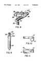
- FIG. 1is a side elevational view of a fixation assembly comprising a clamp according to the invention showing the support rod in cross-section;
- FIG. 2is a plan view of the fixation assembly of FIG. 1;
- FIG. 3is a side view of the fixation assembly of FIGS. 1 and 2, partially cut away to show the entire head of the pedicle screw;
- FIG. 4is a side view of another embodiment of a fixation assembly comprising a clamp according to the invention.
- FIG. 5is a plan view of the clamp and pedicle screw of FIG. 4;
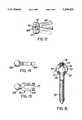
- FIG. 6is a perspective view of another embodiment of a fixation assembly comprising a clamp according to the invention.
- FIG. 7is a top view of the clamp of FIG. 6.
- FIG. 8is a perspective view of another embodiment of a fixation assembly comprising a clamp according to the invention.
- FIG. 9is a vertical view of the pedicle screw of the assembly of FIG. 8;
- FIG. 10is a vertical view of the clamp of the assembly of FIG. 8;
- FIG. 11is a horizontal view of the clamp of the assembly of FIG. 8;
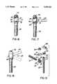
- FIG. 12is a top view of another embodiment of part of a fixation assembly comprising a clamp according to the invention.
- FIG. 13is plan view of the clamp of the assembly of FIG. 12;
- FIG. 14is a side view of the clamp of the assembly of FIG. 12;
- FIG. 15is a frontal view, partly in section, of the pedicle screw of the assembly of FIG. 12;
- FIG. 16is a lateral view, partly in section, of the pedicle screw of the clamp of the assembly of FIG. 12;
- FIG. 17is a schematic view showing the fixation of the clamp of the assembly of FIG. 12 in the head region of the pedicle screw of FIG. 16;
- FIG. 18is a lateral view of the partial assembly of FIG. 17;
- FIG. 19is an exploded view of a preferred embodiment of a fixation assembly according to the invention.
- FIG. 20is a plan view of the clamp of the assembly of FIG. 19;
- FIG. 21is a side view of the clamp of the assembly of FIG. 19;
- FIG. 22is a side view of the hook of the assembly of FIG. 19;
- FIG. 23is a top view of the hook of the assembly of FIG. 19.
- FIG. 24is a perspective view of the assembly of FIG. 19.
- a clamp 9holds a support rod 10, which is preferably threaded, and a pedicle screw 12 in a fixed position, more or less perpendicular to each other.
- the clamp 9comprises a jaw 9a having an upper section 14 and a lower section 16, connected to each other by a C-shaped extension 14a of the upper section 14 which engages a flange 16a of the lower section 16 to form a hinge 18.
- upper and lower sections 14 and 16are shaped to form a socket 8 (as represented in FIG. 3) adapted to accommodate the head 7 of the pedicle screw 12.
- the pedicle screw 12has an essentially spherical head 7.
- the upper section 14 of jaw 9ahas an aperture 14b providing access to the screw head 7.
- Lower section 16has an aperture 16b to accommodate the shaft of the pedicle screw 12.
- the surface of the head 7 of pedicle screw 12may be roughened to provide better grip by the clamp 9.
- the inner surfaces of the socket 8 which holds the head 7may also be roughened.
- Compression meansare provided to press the upper and lower sections 14 and 16 of the jaw 9a together.
- the compression meansmay be a hook 20.
- the upper and lower sections 14 and 16are bifurcated to provide a through slot 26.
- the shaft 20a of hook 20passes through this slot 26.
- the bight 20b of hook 20forms a space under lower section 16 adapted to receive a support rod 10.
- the inner surface of bight 20bmay be threaded or otherwise roughened to engage threads or a roughened surface on support rod 10.
- the lower surface of lower section 16may be threaded, knurled or otherwise roughened in the area where it contacts support rod 10, in order to engage threads or the like on support rod 10.
- the textured surfacesprovide for a better grip on the support rod 10, which must be held firmly in place.
- the upper surface of upper section 14has toothed areas 24 along the sides of through slot 26.
- a small retaining plate 28 with teeth 28a on one surfacerests on top of and bridges the toothed areas 24, with the two sets of teeth interlocking.
- the distance between the axis of shaft 20a of hook 20 and the central axis of pedicle screw 12can be varied by moving the small toothed plate 28 along the length of through slot 26.
- Nut 22is threaded on the hook shaft 20a on top of plate 28. Tightening nut 22 locks plate 28 and hook 20 into the desired place along through slot 26.
- the pedicle screw 12is first run through the aperture 16b in the lower jaw section 16 and inserted into the bone, using the hexagonal socket 30 in the head 7 of the pedicle screw 12 to receive a suitable tool.
- the upper section 14is then engaged with lower section 16 to form a jaw 9a.
- Hook 20is loosely inserted in through slot 26 and the support rod 10 inserted in the bight 20b of the hook 20, the hook 20 being moved along the through slot 26 to the desired position.
- FIGS. 4 and 5Another embodiment of the invention is shown in FIGS. 4 and 5.
- Clamp 35comprises a bifurcated upper section 36 and a lower section 37, connected to each other by a hinge 38 with a pin 39.
- On one side of pedicle screw 12 opposite the hinge 38are two threaded screws 40. These screws hold upper section 36 and lower section 37 together, thus locking the head 7 of pedicle screw 12 in place.
- FIG. 5shows two screws 40, but in an alternative embodiment, a single screw 40 may be used.
- Lower section 37is shorter than upper section 36, as shown in FIG. 4.
- a hook 20 as described in connection with FIGS. 1-3passes through the slot 26 formed by the bifurcation of upper section 36 and holds a support rod 10 against the lower surface of upper section 36. It should be evident that the configuration of the toothed upper surface 24, small retaining plate 28 and nut 22 described in connection with FIGS. 1-3 is applicable to this embodiment as well.
- FIGS. 4 and 5Use of the embodiment of FIGS. 4 and 5 is parallel to that of FIGS. 1-3.
- FIGS. 6 and 7Another embodiment of the invention is shown in FIGS. 6 and 7.
- the head 7 of the pedicle screw 12instead of being clamped by two hinged elements is held between two sections of a block which are joined by screws or bolts.
- the clamp in this embodimentcomprises a block 50 having a front section 44 and a back section 46.
- Front section 44has a bifurcated extension 45 which forms a slot 26.
- a hook 20As shown in FIG. 6 a hook 20, support rod 10, toothed upper surface 24, small toothed plate 28 and nut 22 are provided as described above in connection with FIGS. 1-5.
- Front section 44has two screw holes 49 through it. As shown in FIG. 6, these screw holes 49 are at an angle of about 45° to the top surface of the clamp or the axis of the pedicle screw 12 to be retained in the clamp. These screw holes 49 continue into back section 46 at the same angle. In a preferred embodiment, only the parts of screw holes 49 which are in the back section 46 are threaded, while screws 47 may be partially or wholly threaded.
- Front and back sections 44 and 46are shaped to form a socket 48 which accommodates the head 7 of a pedicle screw 12. Engagement of screws 47 into the threaded holes in back section 46 forces the back section 46 against front section 44 and secures pedicle screw 12 in its desired position.
- the pedicle screw 12is first inserted into the bone.
- Front section 44is placed on the front of the screw head 7, with a hook 20 inserted in slot 26 and the support rod 10 held in the bight of the hook 20.
- back section 46is placed on the back of the pedicle screw head 7.
- Screws 47are inserted into screw holes 49 and tightened. In the embodiment shown in FIG. 6, screws 47 have hexagonal holes in their heads to receive a tool for tightening them.
- the screws 47are put in straight from back section 46 to front section 44, with the axis of the screw holes 49 parallel to the bifurcated extension 45 or generally perpendicular to the axis of the pedicle screw 12.
- extension 45may be flanged as shown in FIG. 6, or they may have a simple rectangular cross-section, on any of the embodiments of the invention,
- FIGS. 8 to 11Another embodiment of the invention is shown in FIGS. 8 to 11.
- the clamp 60has a front section 54 and a back section 56 forming a single block, the front section 54 having a cylindrical bore 53 for receiving the support rod 10 and the back section 56 having a slot 51 for adjustably receiving the head region 57 of a pedicle screw 52.
- a screw hole 61is formed in front section 54, extending into the bore 53.
- the bore 53can either have a smooth surface or preferably a roughened surface (threads or longitudinal grooves), at least on the side opposite screw hole 61, said roughened surface being similar to a corresponding texture on the surface of support rod 10.
- the head region 57 of the pedicle screw 52is designed as a threaded cylinder insertable into the longitudinal slot 51 of the back section 56. Head region 57 can be adjustably secured against back section 56 of the clamp 60 by means of the nut 58 which when tightened presses back section 56 against the shoulder 55A of the screw. For the ease of insertion of the pedicle screw 52 into the bone, the head region 57 is provided with a central hexagonal bore 62.
- Fixation of the support rod 10occurs by means of the screw 59 in the screw hole 61 of the front section 54 of the clamp 60, allowing the releasable fixation--against longitudinal and rotational movement--of the support rod 10 with respect to the clamp 60.
- pedicle screw 52is inserted into the bone.
- Support rod 10is inserted through bore 53 and clamp 60 is placed over the head region 57 at pedicle screw 52.
- head region 57is located in the optimal position in slot 51, nut 58 is tightened over head region 57 and screw 59 is tightened against support rod 10.
- FIGS. 12 to 18Another embodiment of the invention is shown in FIGS. 12 to 18.
- the clamp 70is similar to clamp 35 of FIG. 5; the difference being that the head of the pedicle screw is not clamped by a socket formed by the upper and lower sections of the clamp, but the head provides means for clamp 70 itself to be fixed into the head of the pedicle screw.
- Clamp 70therefore has a front section 64 and a back section 66 forming a single element, the front section 64 being bifurcated, in the same way as clamp 35 of FIG. 5, to form a slot 71 extending through it, the back section 66 forming a spherical head for rotatable fixation into the head region 77 of a pedicle screw 72.
- the head region 77 of the pedicle screw 72has a frontally accessible socket 73 into which the spherical head of the back section 66 of the clamp 70 can be inserted and secured by means of the central set screw 74.
- Central set screw 74can be tightened by means of the central hexagonal socket 75 into a corresponding screw hole 76 in the head region 77.
- Fixation of the spherical head 66 in the socket 73occurs by means of two anchoring points 78 incorporated in the lower half of the head region 77 and third anchoring point 79 incorporated in the lower surface of the central screw 74.
- Socket 73has a circular back opening 81 and a circular front opening 82, said back opening 81 having a diameter smaller than the diameter of spherical head 66 and said front opening 82 having a diameter larger than the diameter of spherical head 66.
- the spherical head 66can be securely fixed in the socket 73, as shown in FIG. 17, by means of the points 78, 79 against the annular rim 83 of back opening 81.
- this embodiment of the inventionallows the angular adjustment of the clamp 70 relative to the pedicle screw 72.
- Fixation of the support rod 10is achieved in the same way as for clamp 35 of FIG. 4 by means of a suitable hook 20, as described in connection with FIGS. 1-3, which passes through the slot 71 formed by the bifurcation of front section 64 and holds a support rod 10 against its lower surface. It should be evident that the configuration of the toothed upper surface 24, small retaining plate 28 and nut 22 described in connection with FIGS. 1-3 is applicable to this embodiment as well.
- pedicle screw 72is first inserted into the bone.
- Back section 66 of clamp 70is inserted into the head region 77 of pedicle screw 72.
- back section 66is secured by tightening central screw 74.
- Hook 20, carrying support rod 10is inserted and secured in slot 71 as in the manner of use of the embodiment according to FIGS. 1-3.
- FIGS. 19 to 24Still another embodiment of the invention is shown in FIGS. 19 to 24.
- clamp 90is somewhat similar to clamp 70 of FIG. 13, the difference being that the bifurcated front section 84 is not connected to a spherical head but to a threaded longitudinal cylindrical section.
- Clamp 90therefore has a front section 84 and a back section 86 forming a single element, the front section 84 being bifurcated in the same way as clamp 70 of FIG. 13 to form a slot 91 extending through it, the back section 86 forming a longitudinal cylindrical section 86 which is threaded for fixation in the head region 97 of a pedicle screw 92.
- the head region 97 of pedicle screw 92is also bifurcated forming a slot 85 for receiving the back section 86 of clamp 90, which can be secured by means of the screw cap 93.
- Screw cap 93has a coaxial inner cylindrical portion (not-represented) with reduced diameter which is threaded on its surface for engagement with the inner thread 87 of the bifurcated head region 97 of the pedicle screw 92.
- Screw cap 93may be fastened to the head region 97 by means of a hexagonal screw driver engaging the hexagonal socket 88 of screw cap 93.
- Fixation of the support rod 10is achieved in a similar way as for clamp 35 of FIG. 4 by means of a suitable hook 94 as described in connection with FIGS. 1-3.
- the hook 94has a threaded portion 95 in the inner concavity of its curved portion 99 and an outer threaded portion 98 on its straight portion 100.
- the straight portion 100 of the hook 94passes through the slot 91 formed by the bifurcation of front section 84 and upon fixation with the nut 96 on the threaded portion 98 holds a support rod 10 against its lower threaded surface 95.
- the configuration of the toothed upper surface 24, small retaining plate 28 and nut 22 described in connection with FIGS. 1-3is applicable to this embodiment as well.
- pedicle screw 92is inserted into the bone.
- Back section 86is placed in the slot 85 of bifurcated head region 97.
- the shaft of hook 94is placed in slot 91 and support rod 10 is threaded through its bight.
- the distance between pedicle screw 92 and rod 10is adjusted and the nut 22 is fastened over small retaining plate 28 (as described in connection with FIGS. 1-3) to secure the hook and screw cap 93 is fastened in head region 97 by means of hexagonal socket 88 to secure the pedicle screw.
- a clamp according to the inventionpermits movement of the support rod relative to the pedicle screw.
- the surgeoncan therefore regulate the horizontal distance between the pedicle screw and the support rod. Because the spherical head of the pedicle screw may be tilted in its socket, the angle between the pedicle screw and the support rod may also be adjusted.
- the clamp according to the inventionpermits the surgeon to adjust each pedicle screw to the specific configuration required by a particular patient.
Landscapes
- Health & Medical Sciences (AREA)
- Orthopedic Medicine & Surgery (AREA)
- Life Sciences & Earth Sciences (AREA)
- Neurology (AREA)
- Surgery (AREA)
- Heart & Thoracic Surgery (AREA)
- Engineering & Computer Science (AREA)
- Biomedical Technology (AREA)
- Nuclear Medicine, Radiotherapy & Molecular Imaging (AREA)
- Medical Informatics (AREA)
- Molecular Biology (AREA)
- Animal Behavior & Ethology (AREA)
- General Health & Medical Sciences (AREA)
- Public Health (AREA)
- Veterinary Medicine (AREA)
- Surgical Instruments (AREA)
Abstract
Description
This is a continuation of copending application Ser. No. 07/614,155 filed Nov. 16, 1990 now abandoned which is a continuation-in-part of application Ser. No. 07/428,907, filed Oct. 30, 1989, now U.S. Pat. No. 5,002,542.
This invention relates to an osteosynthetic clamp for attaching a pedicle screw to a spinal support rod and a fixation assembly comprising a clamp, support rod and a pedicle screw.
Pedicle screws held by clamps in osteosynthetic assemblies are one type of implant used for treating spinal injuries and deformities. In one common treatment the pedicle screws are driven into the pedicles of vertebrae above and below the injured vertebra or vertebrae. A supporting rod is attached to the pedicle screws, for example, by clamps or by threading it through slots in the pedicle screws. The supporting rod holds the spinal column approximately in its desired alignment, thereby relieving pressure on the injured vertebra or vertebrae and permitting it to heal and regain its natural conformation.
One type of pedicle screw is disclosed in U.S. Pat. No. 4,887,596, filed Mar. 2, 1988, commonly owned herewith.
As noted, clamps may be used to connect rigidly the part of the pedicle screw protruding from the vertebra to a spinal support rod. In most of these known clamps the pedicle screw and the supporting rod are arranged in the same plane allowing no adjustment to anatomical requirements.
In another known type of pedicle screw clamp (according to AT-B 387,710 to Sulzer) the central axis of the pedicle screw and the central axis of the support rod are located in different planes but are still maintained at a fixed, non-adjustable distance, again preventing the surgeon from adapting the clamp to anatomical needs. Furthermore, these known pedicle screw clamps do not permit relative angular adjustment of the pedicle screw and the support rod. Thus, current clamps do not allow sufficient adjustment to the specific alignment required by each patient's needs.
The invention as claimed is intended to remedy these drawbacks. It solves the problem of how to design an osteosynthetic clamp for attaching a pedicle screw or spinal hook to a spinal support rod with an adjustable distance between the central axis of the pedicle screw and the central axis of the support rod, and at the same time permitting angular adjustment of the central axis of the pedicle screw relative to the central axis of the support rod.
The invention comprises a clamp for attaching a spinal implant such as a pedicle screw or spinal hook to a support rod. The clamp comprises a first holding means for holding the implant and a second holding means for holding the rod, the holding means permitting adjustment of the longitudinal axes of the implant and the rod relative to one another. The invention also comprises a fixation assembly comprising the clamp, support rod and pedicle screw.
In a preferred embodiment the clamp may comprise two sections adapted to receive the head of a pedicle screw, a hook which holds the support rod at an adjustable distance from the pedicle screw and compression means which holds the two sections together so that they tightly clamp the head of the pedicle screw.
In one aspect the invention comprises a clamp having a jaw with upper and lower sections, hinged at one end, said sections being bifurcated to form a slot extending through the sections, a socket formed in the jaw for receiving the head of a pedicle screw and compression means movable relative to said socket for forcing the jaws together, said compression means being adapted to receive a support rod and being operable to urge said rod against the jaw as the jaw sections are forced together.
In another aspect the invention comprises a clamp having a jaw with an upper section and a shorter lower section, hinged at one end, said upper section being bifurcated to form a slot extending through it, a socket formed in the jaw for receiving the head of a pedicle screw, receiving means which receives a support rod and holds the support rod against the lower surface of the upper section, and compression means, such as a screw extending through the upper and lower sections, which forces them together so as to grasp the head of the pedicle screw.
In another aspect the invention comprises a clamp having front and back sections which form a socket for the pedicle screw head, the front section having a bifurcated extension. The clamp further comprises receiving means which receives a support rod and compression means, such as a screw which holds the front and back sections together, grasping the head of the pedicle screw.
In another aspect the invention includes a fixation assembly comprising a clamp as described, a pedicle screw having a head shaped to engage the socket and a support rod.
In a further aspect the invention comprises a clamp having a front and a back section forming one single block, the front section having a cylindrical bore for receiving the support rod and the back section having a slot for adjustably receiving the head of a pedicle screw.
In still another aspect the invention comprises a clamp having a front and a back section forming a single element, the front section being bifurcated to form a slot extending through it, the back section forming a spherical head for rotatable fixation into the head region of a pedicle screw.
The main advantages offered by the invention are:
ease of manipulation by the surgeon;
adaptability of the system, because each pedicle screw may be placed at a different distance from the support rod; and
the possibility of using not only deformable support rods, but also rigid support rods which offer increased mechanical strength.
For better understanding of the invention, its operating advantages and the specific objects attained by its use, reference should be had to the accompanying drawings and descriptive matter in which are illustrated and described preferred embodiments of the invention.
In the drawings:
FIG. 1 is a side elevational view of a fixation assembly comprising a clamp according to the invention showing the support rod in cross-section;
FIG. 2 is a plan view of the fixation assembly of FIG. 1;
FIG. 3 is a side view of the fixation assembly of FIGS. 1 and 2, partially cut away to show the entire head of the pedicle screw;
FIG. 4 is a side view of another embodiment of a fixation assembly comprising a clamp according to the invention;
FIG. 5 is a plan view of the clamp and pedicle screw of FIG. 4;
FIG. 6 is a perspective view of another embodiment of a fixation assembly comprising a clamp according to the invention;
FIG. 7 is a top view of the clamp of FIG. 6.
FIG. 8 is a perspective view of another embodiment of a fixation assembly comprising a clamp according to the invention;
FIG. 9 is a vertical view of the pedicle screw of the assembly of FIG. 8;
FIG. 10 is a vertical view of the clamp of the assembly of FIG. 8;
FIG. 11 is a horizontal view of the clamp of the assembly of FIG. 8;
FIG. 12 is a top view of another embodiment of part of a fixation assembly comprising a clamp according to the invention;
FIG. 13 is plan view of the clamp of the assembly of FIG. 12;
FIG. 14 is a side view of the clamp of the assembly of FIG. 12;
FIG. 15 is a frontal view, partly in section, of the pedicle screw of the assembly of FIG. 12;
FIG. 16 is a lateral view, partly in section, of the pedicle screw of the clamp of the assembly of FIG. 12;
FIG. 17 is a schematic view showing the fixation of the clamp of the assembly of FIG. 12 in the head region of the pedicle screw of FIG. 16;
FIG. 18 is a lateral view of the partial assembly of FIG. 17;
FIG. 19 is an exploded view of a preferred embodiment of a fixation assembly according to the invention;
FIG. 20 is a plan view of the clamp of the assembly of FIG. 19;
FIG. 21 is a side view of the clamp of the assembly of FIG. 19;
FIG. 22 is a side view of the hook of the assembly of FIG. 19;
FIG. 23 is a top view of the hook of the assembly of FIG. 19; and
FIG. 24 is a perspective view of the assembly of FIG. 19.
As shown in FIG. 1, a clamp 9 according to the invention holds asupport rod 10, which is preferably threaded, and apedicle screw 12 in a fixed position, more or less perpendicular to each other. The clamp 9 comprises a jaw 9a having anupper section 14 and a lower section 16, connected to each other by a C-shaped extension 14a of theupper section 14 which engages aflange 16a of the lower section 16 to form ahinge 18. Towards their ends nearhinge 18, upper andlower sections 14 and 16 are shaped to form a socket 8 (as represented in FIG. 3) adapted to accommodate thehead 7 of thepedicle screw 12. In a preferred embodiment of the assembly comprising a clamp according to the invention as shown in FIG. 3, thepedicle screw 12 has an essentiallyspherical head 7. Theupper section 14 of jaw 9a has anaperture 14b providing access to thescrew head 7. Lower section 16 has an aperture 16b to accommodate the shaft of thepedicle screw 12.
The surface of thehead 7 ofpedicle screw 12 may be roughened to provide better grip by the clamp 9. The inner surfaces of thesocket 8 which holds thehead 7 may also be roughened.
Compression means are provided to press the upper andlower sections 14 and 16 of the jaw 9a together. As shown in FIGS. 1 to 3 the compression means may be ahook 20. As shown in FIGS. 2 and 3, the upper andlower sections 14 and 16 are bifurcated to provide a throughslot 26. The shaft 20a ofhook 20 passes through thisslot 26. The bight 20b ofhook 20 forms a space under lower section 16 adapted to receive asupport rod 10. The inner surface ofbight 20b may be threaded or otherwise roughened to engage threads or a roughened surface onsupport rod 10. The lower surface of lower section 16 may be threaded, knurled or otherwise roughened in the area where it contacts supportrod 10, in order to engage threads or the like onsupport rod 10. The textured surfaces provide for a better grip on thesupport rod 10, which must be held firmly in place.
The upper surface ofupper section 14 has toothedareas 24 along the sides of throughslot 26. Asmall retaining plate 28 withteeth 28a on one surface rests on top of and bridges thetoothed areas 24, with the two sets of teeth interlocking. The distance between the axis of shaft 20a ofhook 20 and the central axis ofpedicle screw 12 can be varied by moving the smalltoothed plate 28 along the length of throughslot 26.Nut 22 is threaded on the hook shaft 20a on top ofplate 28. Tighteningnut 22locks plate 28 andhook 20 into the desired place along throughslot 26.
In using the device according to the invention, thepedicle screw 12 is first run through the aperture 16b in the lower jaw section 16 and inserted into the bone, using thehexagonal socket 30 in thehead 7 of thepedicle screw 12 to receive a suitable tool. Theupper section 14 is then engaged with lower section 16 to form a jaw 9a.Hook 20 is loosely inserted in throughslot 26 and thesupport rod 10 inserted in the bight 20b of thehook 20, thehook 20 being moved along the throughslot 26 to the desired position. When pedicle screw 12 andsupport rod 10 are at the optimum distance from one another and at the proper angle,nut 22 is turned down on the shaft 20a of thehook 20, forcing thejaw sections 14 and 16 together to clamp thehead 7 of thepedicle screw 12 in itssocket 8 and presssupport rod 10 firmly against lower section 16. The leverage provided by the jaw construction 9a enables thepedicle screw 12 to be tightly fixed in its selected position relative to thesupport rod 10.
Another embodiment of the invention is shown in FIGS. 4 and 5.Clamp 35 comprises a bifurcatedupper section 36 and alower section 37, connected to each other by ahinge 38 with a pin 39. On one side ofpedicle screw 12 opposite thehinge 38 are two threadedscrews 40. These screws holdupper section 36 andlower section 37 together, thus locking thehead 7 ofpedicle screw 12 in place. FIG. 5 shows twoscrews 40, but in an alternative embodiment, asingle screw 40 may be used.
Use of the embodiment of FIGS. 4 and 5 is parallel to that of FIGS. 1-3.
Another embodiment of the invention is shown in FIGS. 6 and 7. In this embodiment thehead 7 of thepedicle screw 12 instead of being clamped by two hinged elements is held between two sections of a block which are joined by screws or bolts.
Referring to FIG. 6, the clamp in this embodiment comprises ablock 50 having afront section 44 and aback section 46.Front section 44 has a bifurcatedextension 45 which forms aslot 26. As shown in FIG. 6 ahook 20,support rod 10, toothedupper surface 24, smalltoothed plate 28 andnut 22 are provided as described above in connection with FIGS. 1-5.Front section 44 has twoscrew holes 49 through it. As shown in FIG. 6, these screw holes 49 are at an angle of about 45° to the top surface of the clamp or the axis of thepedicle screw 12 to be retained in the clamp. These screw holes 49 continue intoback section 46 at the same angle. In a preferred embodiment, only the parts of screw holes 49 which are in theback section 46 are threaded, whilescrews 47 may be partially or wholly threaded.
Front andback sections socket 48 which accommodates thehead 7 of apedicle screw 12. Engagement ofscrews 47 into the threaded holes inback section 46 forces theback section 46 againstfront section 44 and securespedicle screw 12 in its desired position.
When using this embodiment of the invention, thepedicle screw 12 is first inserted into the bone.Front section 44 is placed on the front of thescrew head 7, with ahook 20 inserted inslot 26 and thesupport rod 10 held in the bight of thehook 20. When thepedicle screw 12 and thesupport rod 10 are adjusted to the optimum distance and angle, backsection 46 is placed on the back of thepedicle screw head 7.Screws 47 are inserted into screw holes 49 and tightened. In the embodiment shown in FIG. 6, screws 47 have hexagonal holes in their heads to receive a tool for tightening them.
The 45° degree angles make it easier for the surgeon to reach thescrews 47. In an alternative configuration (not shown) thescrews 47 are put in straight fromback section 46 tofront section 44, with the axis of the screw holes 49 parallel to thebifurcated extension 45 or generally perpendicular to the axis of thepedicle screw 12.
The ends ofextension 45 may be flanged as shown in FIG. 6, or they may have a simple rectangular cross-section, on any of the embodiments of the invention,
Another embodiment of the invention is shown in FIGS. 8 to 11. In this embodiment theclamp 60 has afront section 54 and aback section 56 forming a single block, thefront section 54 having acylindrical bore 53 for receiving thesupport rod 10 and theback section 56 having aslot 51 for adjustably receiving thehead region 57 of apedicle screw 52. Ascrew hole 61 is formed infront section 54, extending into thebore 53.
Thebore 53 can either have a smooth surface or preferably a roughened surface (threads or longitudinal grooves), at least on the side oppositescrew hole 61, said roughened surface being similar to a corresponding texture on the surface ofsupport rod 10. Upon fastening of ascrew 59 inscrew hole 61,support rod 10 is pressed against the roughened surface ofbore 53 thereby producing a firm fixation.
Thehead region 57 of thepedicle screw 52 is designed as a threaded cylinder insertable into thelongitudinal slot 51 of theback section 56.Head region 57 can be adjustably secured againstback section 56 of theclamp 60 by means of thenut 58 which when tightened presses backsection 56 against theshoulder 55A of the screw. For the ease of insertion of thepedicle screw 52 into the bone, thehead region 57 is provided with a central hexagonal bore 62.
Fixation of thesupport rod 10 occurs by means of thescrew 59 in thescrew hole 61 of thefront section 54 of theclamp 60, allowing the releasable fixation--against longitudinal and rotational movement--of thesupport rod 10 with respect to theclamp 60.
When using the embodiment of the invention shown in FIGS. 8 to 11,pedicle screw 52 is inserted into the bone.Support rod 10 is inserted throughbore 53 andclamp 60 is placed over thehead region 57 atpedicle screw 52. Whenhead region 57 is located in the optimal position inslot 51,nut 58 is tightened overhead region 57 andscrew 59 is tightened againstsupport rod 10.
Another embodiment of the invention is shown in FIGS. 12 to 18. In this embodiment theclamp 70 is similar to clamp 35 of FIG. 5; the difference being that the head of the pedicle screw is not clamped by a socket formed by the upper and lower sections of the clamp, but the head provides means forclamp 70 itself to be fixed into the head of the pedicle screw.
Thehead region 77 of thepedicle screw 72 has a frontallyaccessible socket 73 into which the spherical head of theback section 66 of theclamp 70 can be inserted and secured by means of thecentral set screw 74.Central set screw 74 can be tightened by means of the centralhexagonal socket 75 into acorresponding screw hole 76 in thehead region 77. Fixation of thespherical head 66 in thesocket 73 occurs by means of twoanchoring points 78 incorporated in the lower half of thehead region 77 andthird anchoring point 79 incorporated in the lower surface of thecentral screw 74.Socket 73 has a circular back opening 81 and acircular front opening 82, said back opening 81 having a diameter smaller than the diameter ofspherical head 66 and saidfront opening 82 having a diameter larger than the diameter ofspherical head 66. By this construction thespherical head 66 can be securely fixed in thesocket 73, as shown in FIG. 17, by means of thepoints annular rim 83 ofback opening 81.
As shown in FIG. 18, this embodiment of the invention allows the angular adjustment of theclamp 70 relative to thepedicle screw 72.
Fixation of thesupport rod 10 is achieved in the same way as forclamp 35 of FIG. 4 by means of asuitable hook 20, as described in connection with FIGS. 1-3, which passes through theslot 71 formed by the bifurcation offront section 64 and holds asupport rod 10 against its lower surface. It should be evident that the configuration of the toothedupper surface 24, small retainingplate 28 andnut 22 described in connection with FIGS. 1-3 is applicable to this embodiment as well.
In the use of the embodiment shown in FIGS. 12-18,pedicle screw 72 is first inserted into the bone.Back section 66 ofclamp 70 is inserted into thehead region 77 ofpedicle screw 72. After adjusting the clamp to the correct angle with respect to the pedicle screw, backsection 66 is secured by tighteningcentral screw 74.Hook 20, carryingsupport rod 10, is inserted and secured inslot 71 as in the manner of use of the embodiment according to FIGS. 1-3.
Still another embodiment of the invention is shown in FIGS. 19 to 24. In thisembodiment clamp 90 is somewhat similar to clamp 70 of FIG. 13, the difference being that thebifurcated front section 84 is not connected to a spherical head but to a threaded longitudinal cylindrical section.Clamp 90 therefore has afront section 84 and aback section 86 forming a single element, thefront section 84 being bifurcated in the same way asclamp 70 of FIG. 13 to form aslot 91 extending through it, theback section 86 forming a longitudinalcylindrical section 86 which is threaded for fixation in thehead region 97 of apedicle screw 92.
Thehead region 97 ofpedicle screw 92 is also bifurcated forming aslot 85 for receiving theback section 86 ofclamp 90, which can be secured by means of thescrew cap 93.Screw cap 93 has a coaxial inner cylindrical portion (not-represented) with reduced diameter which is threaded on its surface for engagement with theinner thread 87 of thebifurcated head region 97 of thepedicle screw 92.Screw cap 93 may be fastened to thehead region 97 by means of a hexagonal screw driver engaging thehexagonal socket 88 ofscrew cap 93.
Fixation of thesupport rod 10 is achieved in a similar way as forclamp 35 of FIG. 4 by means of asuitable hook 94 as described in connection with FIGS. 1-3. Thehook 94 has a threadedportion 95 in the inner concavity of itscurved portion 99 and an outer threadedportion 98 on itsstraight portion 100. Thestraight portion 100 of thehook 94 passes through theslot 91 formed by the bifurcation offront section 84 and upon fixation with the nut 96 on the threadedportion 98 holds asupport rod 10 against its lower threadedsurface 95. It should be evident that the configuration of the toothedupper surface 24, small retainingplate 28 andnut 22 described in connection with FIGS. 1-3 is applicable to this embodiment as well.
In using the device according to FIGS. 19-24,pedicle screw 92 is inserted into the bone.Back section 86 is placed in theslot 85 ofbifurcated head region 97. The shaft ofhook 94 is placed inslot 91 andsupport rod 10 is threaded through its bight. The distance betweenpedicle screw 92 androd 10 is adjusted and thenut 22 is fastened over small retaining plate 28 (as described in connection with FIGS. 1-3) to secure the hook andscrew cap 93 is fastened inhead region 97 by means ofhexagonal socket 88 to secure the pedicle screw.
The various surfaces described in connection with FIGS. 1-3, as being roughened to provide better grip may of course be employed in the other embodiments too.
From a consideration of the foregoing description it will be evident that a clamp according to the invention permits movement of the support rod relative to the pedicle screw. The surgeon can therefore regulate the horizontal distance between the pedicle screw and the support rod. Because the spherical head of the pedicle screw may be tilted in its socket, the angle between the pedicle screw and the support rod may also be adjusted. Thus the clamp according to the invention permits the surgeon to adjust each pedicle screw to the specific configuration required by a particular patient.
Although the invention has been described as applied to a pedicle screw, it is clearly also applicable to other spinal implant devices such as spinal hooks.
Claims (6)
1. A unitary consisting of a device for attaching a single pedicle screw or spinal hook to a single support rod, said pedicle screw or spinal hook and said support rod having longitudinal axes and being positioned in different planes relative to one another so that there is no plane totally encompassing both axes, said screw or hook having an enlarged head, said device having first holding means comprising a socket, adjustable in size, adapted to receive the head of said screw or hook, and said device further having second holding means adapted for holding said support rod, said two holding means being adjustable to vary the inclination of said axes relative to one another and the distance of said axes from one another.
2. A fixation assembly comprising a support rod and a pedicle screw or hook, said support rod and said screw or hook being held by the clamp of claim 1.
3. The clamp as claimed in claim 1, wherein said second holding means comprises a bifurcated front section and receiving means for receiving the support rod, said receiving means being movable relative to said front section, and wherein said first holding means includes compression means for fixing the enlarged screw head within said socket.
4. The clamp claimed in claim 1, wherein said second holding means comprises a front section having a hook for receiving the support rod and first compression means for fixing the support rod in said hook and wherein the first holding means comprises second compression means for fixing the head of a pedicle screw or hook inserted in said socket.
5. The clamp claimed in claim 1, wherein the second holding means comprises a front section having a through slot, receiving means in said slot for receiving the support rod, and first compression means for fixing the support rod in said receiving means, and wherein the first holding means comprises a second compression means for fixing the head region of a pedicle screw in said socket.
6. A clamp for attaching a pedicle screw or spinal hook to a spinal support rod comprising:
a first section and a second section, at least one of said sections being bifurcated to form a slot;
a socket formed in said first and second sections to receive the head of a pedicle screw or spinal hook, said screw or hook having a longitudinal axis;
receiving means for receiving and holding a support rod having a longitudinal axis in a position such that the axis of said support rod is in a different plane from the axis of a screw or hook whose head is seated in said socket, there being no plane encompassing both axes;
said receiving means being movable relative to said socket to permit adjustment of the distance between said axes; and
compression means for forcing said two sections together to secure the head of the screw or hook in said socket.
Priority Applications (1)
| Application Number | Priority Date | Filing Date | Title |
|---|---|---|---|
| US07/989,872US5344422A (en) | 1989-10-30 | 1992-12-10 | Pedicular screw clamp |
Applications Claiming Priority (5)
| Application Number | Priority Date | Filing Date | Title |
|---|---|---|---|
| US07/428,907US5002542A (en) | 1989-10-30 | 1989-10-30 | Pedicle screw clamp |
| EP90116070AEP0425783B1 (en) | 1989-10-30 | 1990-08-22 | Pedicle screw clamp |
| EP90116070.5 | 1990-08-22 | ||
| US61415590A | 1990-11-16 | 1990-11-16 | |
| US07/989,872US5344422A (en) | 1989-10-30 | 1992-12-10 | Pedicular screw clamp |
Related Parent Applications (1)
| Application Number | Title | Priority Date | Filing Date |
|---|---|---|---|
| US61415590AContinuation | 1989-10-30 | 1990-11-16 |
Publications (1)
| Publication Number | Publication Date |
|---|---|
| US5344422Atrue US5344422A (en) | 1994-09-06 |
Family
ID=27233330
Family Applications (1)
| Application Number | Title | Priority Date | Filing Date |
|---|---|---|---|
| US07/989,872Expired - LifetimeUS5344422A (en) | 1989-10-30 | 1992-12-10 | Pedicular screw clamp |
Country Status (1)
| Country | Link |
|---|---|
| US (1) | US5344422A (en) |
Cited By (158)
| Publication number | Priority date | Publication date | Assignee | Title |
|---|---|---|---|---|
| US5474551A (en)* | 1994-11-18 | 1995-12-12 | Smith & Nephew Richards, Inc. | Universal coupler for spinal fixation |
| US5498263A (en)* | 1994-06-28 | 1996-03-12 | Acromed Corporation | Transverse connector for spinal column corrective devices |
| US5545228A (en)* | 1991-08-15 | 1996-08-13 | Smith & Nephew Richards Inc. | Offset bone bolt |
| US5643263A (en)* | 1995-08-14 | 1997-07-01 | Simonson; Peter Melott | Spinal implant connection assembly |
| US5651789A (en)* | 1990-03-08 | 1997-07-29 | Sofamor Danek Group | Transverse fixation device for ensuring a rigid transverse connection between two rods of a spinal osteosynthesis system |
| US5662651A (en)* | 1994-09-15 | 1997-09-02 | Tornier S.A. | External or internal fixator for repairing fractures or arthroplasties of the skeleton |
| US5725528A (en)* | 1997-02-12 | 1998-03-10 | Third Millennium Engineering, Llc | Modular polyaxial locking pedicle screw |
| US5735851A (en)* | 1996-10-09 | 1998-04-07 | Third Millennium Engineering, Llc | Modular polyaxial locking pedicle screw |
| WO1998015233A1 (en)* | 1996-10-09 | 1998-04-16 | Third Millennium Engineering, L.L.C. | A modular polyaxial locking pedicle screw |
| US5743907A (en)* | 1990-07-24 | 1998-04-28 | Acromed Corporation | Spinal column retaining method and apparatus |
| US5782833A (en)* | 1996-12-20 | 1998-07-21 | Haider; Thomas T. | Pedicle screw system for osteosynthesis |
| US5785711A (en)* | 1997-05-15 | 1998-07-28 | Third Millennium Engineering, Llc | Polyaxial pedicle screw having a through bar clamp locking mechanism |
| US5788711A (en)* | 1996-05-10 | 1998-08-04 | Implex Gmgh Spezialhorgerate | Implantable positioning and fixing system for actuator and sensor implants |
| US5810819A (en)* | 1997-05-15 | 1998-09-22 | Spinal Concepts, Inc. | Polyaxial pedicle screw having a compression locking rod gripping mechanism |
| US5928243A (en)* | 1997-07-16 | 1999-07-27 | Spinal Concepts, Inc. | Pedicle probe and depth gage |
| US5935133A (en)* | 1997-08-26 | 1999-08-10 | Spinal Concepts, Inc. | Surgical cable system and method |
| US5947965A (en)* | 1992-12-31 | 1999-09-07 | Bryan; Donald W. | Spinal fixation apparatus and method |
| US5951557A (en)* | 1997-12-30 | 1999-09-14 | Luter; Dennis W. | Bone plate |
| US5976135A (en)* | 1997-12-18 | 1999-11-02 | Sdgi Holdings, Inc. | Lateral connector assembly |
| US5989250A (en)* | 1996-10-24 | 1999-11-23 | Spinal Concepts, Inc. | Method and apparatus for spinal fixation |
| US6001129A (en)* | 1996-08-07 | 1999-12-14 | St. Croix Medical, Inc. | Hearing aid transducer support |
| US6004322A (en)* | 1994-10-25 | 1999-12-21 | Sdgi Holdings, Inc. | Modular pedicle screw system |
| US6030389A (en)* | 1997-08-04 | 2000-02-29 | Spinal Concepts, Inc. | System and method for stabilizing the human spine with a bone plate |
| US6053921A (en)* | 1997-08-26 | 2000-04-25 | Spinal Concepts, Inc. | Surgical cable system and method |
| US6080193A (en)* | 1997-05-01 | 2000-06-27 | Spinal Concepts, Inc. | Adjustable height fusion device |
| US6083226A (en)* | 1998-04-22 | 2000-07-04 | Fiz; Daniel | Bone fixation device and transverse linking bridge |
| US6132430A (en)* | 1996-10-24 | 2000-10-17 | Spinal Concepts, Inc. | Spinal fixation system |
| US6132434A (en)* | 1996-11-07 | 2000-10-17 | Sdgi Holdings, Inc. | Multi-angle bone screw assembly using shape-memory technology |
| US6171311B1 (en)* | 1996-10-18 | 2001-01-09 | Marc Richelsoph | Transverse connector |
| US6176861B1 (en) | 1994-10-25 | 2001-01-23 | Sdgi Holdings, Inc. | Modular spinal system |
| US6179838B1 (en) | 1998-02-24 | 2001-01-30 | Daniel Fiz | Bone fixation arrangements and method |
| EP1090595A2 (en) | 1999-10-07 | 2001-04-11 | Stryker Spine SA | Slotted head pedicle screw assembly |
| US6352537B1 (en) | 1998-09-17 | 2002-03-05 | Electro-Biology, Inc. | Method and apparatus for spinal fixation |
| US6364825B1 (en) | 1998-09-24 | 2002-04-02 | St. Croix Medical, Inc. | Method and apparatus for improving signal quality in implantable hearing systems |
| US20020045898A1 (en)* | 2000-01-06 | 2002-04-18 | Spinal Concepts, Inc. | System and method for stabilizing the human spine with a bone plate |
| WO2002045607A1 (en)* | 2000-12-07 | 2002-06-13 | Spine Next | Device for fixing a rod and a spherical symmetry screw head |
| FR2817928A1 (en)* | 2000-12-07 | 2002-06-14 | Spine Next Sa | Fixing for rod and spherical screw head e.g. for spinal stabilisation implant has lower and upper members shaped to grip screw head and rod |
| US6413257B1 (en)* | 1997-05-15 | 2002-07-02 | Surgical Dynamics, Inc. | Clamping connector for spinal fixation systems |
| US6413258B1 (en) | 1999-08-12 | 2002-07-02 | Osteotech, Inc. | Rod-to-rod coupler |
| US6454769B2 (en) | 1997-08-04 | 2002-09-24 | Spinal Concepts, Inc. | System and method for stabilizing the human spine with a bone plate |
| US6488616B1 (en) | 1996-08-07 | 2002-12-03 | St. Croix Medical, Inc. | Hearing aid transducer support |
| US20030045878A1 (en)* | 1999-12-03 | 2003-03-06 | Dominique Petit | Connecting assembly for spinal osteosynthesis |
| US20030055426A1 (en)* | 2001-09-14 | 2003-03-20 | John Carbone | Biased angulation bone fixation assembly |
| US20030060823A1 (en)* | 2001-09-24 | 2003-03-27 | Bryan Donald W. | Pedicle screw spinal fixation device |
| US6551318B1 (en) | 2000-07-26 | 2003-04-22 | Stahurski Consulting Inc. | Spinal column retaining apparatus |
| US6562038B1 (en) | 2000-03-15 | 2003-05-13 | Sdgi Holdings, Inc. | Spinal implant connection assembly |
| US6572618B1 (en)* | 2000-03-15 | 2003-06-03 | Sdgi Holdings, Inc. | Spinal implant connection assembly |
| US6610063B2 (en) | 2000-07-28 | 2003-08-26 | Synthes (Usa) | Spinal fixation system |
| FR2836368A1 (en)* | 2002-02-25 | 2003-08-29 | Spine Next Sa | Device for connection between rod and spherical screw head comprises longitudinal pieces which cooperate together, first end having upper piece and bent away lower piece having support points for screw head |
| US20030176862A1 (en)* | 2000-10-23 | 2003-09-18 | Taylor Harold Sparr | Taper-locked adjustable connector |
| US6656179B1 (en)* | 1999-10-18 | 2003-12-02 | Bernd Schaefer | Bone plate |
| EP1371338A1 (en)* | 2002-06-11 | 2003-12-17 | Signus Medizintechnik GmbH | Bone screw |
| FR2840798A1 (en)* | 2002-06-14 | 2003-12-19 | Kiscomedica | Bar type spinal osteosynthesis device for maintaining two consecutive spinal vertebrae w.r.t each other has two convex hemispherical parts enclosed by corresponding hemispherical cavities in legs through which threaded bone screw passes |
| US20040002758A1 (en)* | 2002-03-11 | 2004-01-01 | Landry Michael E. | Spinal implant including a compressible connector |
| US20040010253A1 (en)* | 2000-03-15 | 2004-01-15 | Morrison Matthew M. | Spinal implant connection assembly |
| US6685705B1 (en) | 2000-10-23 | 2004-02-03 | Sdgi Holdings, Inc. | Six-axis and seven-axis adjustable connector |
| US6730015B2 (en) | 2001-06-01 | 2004-05-04 | Mike Schugt | Flexible transducer supports |
| US20040087949A1 (en)* | 2002-10-31 | 2004-05-06 | Bono Frank S. | Snap-in washers and assemblies thereof |
| EP1430841A1 (en)* | 2002-12-20 | 2004-06-23 | Zimmer Technology, Inc. | Surgical instrument and method for positioning same |
| US6755830B2 (en) | 2001-07-04 | 2004-06-29 | Sofamor S.N.C. | Connector for a spinal fixation member |
| US20040153077A1 (en)* | 2000-11-10 | 2004-08-05 | Lutz Biedermann | Bone screw |
| US20050049593A1 (en)* | 2003-09-03 | 2005-03-03 | Duong Lan Anh Nguyen | Bone plate with captive clips |
| US6872208B1 (en) | 2000-10-06 | 2005-03-29 | Spinal Concepts, Inc. | Adjustable transverse connector |
| US6887241B1 (en) | 2000-10-06 | 2005-05-03 | Spinal Concepts, Inc. | Adjustable transverse connector with cam activated engagers |
| US20050113830A1 (en)* | 2003-11-24 | 2005-05-26 | Alan Rezach | Grommet assembly |
| US20050143737A1 (en)* | 2003-12-31 | 2005-06-30 | John Pafford | Dynamic spinal stabilization system |
| US20050143823A1 (en)* | 2003-12-31 | 2005-06-30 | Boyd Lawrence M. | Dynamic spinal stabilization system |
| US20050154393A1 (en)* | 2003-12-30 | 2005-07-14 | Thomas Doherty | Bone anchor assemblies and methods of manufacturing bone anchor assemblies |
| US20050154391A1 (en)* | 2003-12-30 | 2005-07-14 | Thomas Doherty | Bone anchor assemblies |
| US20050187548A1 (en)* | 2004-01-13 | 2005-08-25 | Butler Michael S. | Pedicle screw constructs for spine fixation systems |
| US20050194758A1 (en)* | 2004-03-02 | 2005-09-08 | Access Technologies Limited | Pivotable suspension element |
| US20050240181A1 (en)* | 2004-04-23 | 2005-10-27 | Boomer Mark C | Spinal implant connectors |
| US20050240185A1 (en)* | 2004-04-23 | 2005-10-27 | Depuy Spine Sarl | Spinal fixation plates and plate extensions |
| US20050277919A1 (en)* | 2004-05-28 | 2005-12-15 | Depuy Spine, Inc. | Anchoring systems and methods for correcting spinal deformities |
| US20060036252A1 (en)* | 2004-08-12 | 2006-02-16 | Baynham Bret O | Polyaxial screw |
| US20060064088A1 (en)* | 2002-04-04 | 2006-03-23 | Stephane Ramare | Spinal ostesynthesis system |
| US20060149231A1 (en)* | 2004-12-13 | 2006-07-06 | Rsb Spine Llc | Bone fastener assembly for bone retention apparatus |
| US20060229616A1 (en)* | 2005-03-03 | 2006-10-12 | Accin Corporation | Spinal stabilization using bone anchor seat and cross coupling with improved locking feature |
| US7141051B2 (en) | 2003-02-05 | 2006-11-28 | Pioneer Laboratories, Inc. | Low profile spinal fixation system |
| US20070072459A1 (en)* | 2005-09-23 | 2007-03-29 | Stahurski Consulting Inc. | Apparatus for retaining vertebrae |
| US20070191843A1 (en)* | 2006-01-30 | 2007-08-16 | Sdgi Holdings, Inc. | Devices and methods for attaching a rod to a vertebral member |
| US20070270805A1 (en)* | 2006-04-07 | 2007-11-22 | Sdgi Holdings, Inc. | Spinal rod connector system and method for a bone anchor |
| US20070270839A1 (en)* | 2006-04-05 | 2007-11-22 | Dong Myung Jeon | Multi-axial double locking bone screw assembly |
| US20080161863A1 (en)* | 2006-12-28 | 2008-07-03 | Depuy Spine, Inc. | Spinal anchoring screw |
| US20090005817A1 (en)* | 2007-04-30 | 2009-01-01 | Adam Friedrich | Flexible Spine Stabilization System |
| US7485132B1 (en) | 2000-10-06 | 2009-02-03 | Abbott Spine Inc. | Transverse connector with cam activated engagers |
| US20090062822A1 (en)* | 2007-08-31 | 2009-03-05 | Frasier William J | Adaptable clamping mechanism for coupling a spinal fixation element to a bone anchor |
| US20090254125A1 (en)* | 2008-04-03 | 2009-10-08 | Daniel Predick | Top Loading Polyaxial Spine Screw Assembly With One Step Lockup |
| US7635380B2 (en) | 2007-06-05 | 2009-12-22 | Spartek Medical, Inc. | Bone anchor with a compressor element for receiving a rod for a dynamic stabilization and motion preservation spinal implantation system and method |
| US7666185B2 (en) | 2003-09-03 | 2010-02-23 | Synthes Usa, Llc | Translatable carriage fixation system |
| US20100049253A1 (en)* | 2008-08-20 | 2010-02-25 | Warsaw Orthopedic, Inc. | Bottom loading connector for attaching a spinal rod to a vertebral member |
| US20100100136A1 (en)* | 2008-10-17 | 2010-04-22 | Omni Surgical, D/B/A Spine 360 | Poly-axial pedicle scre implements and lock screw therefor |
| US7736380B2 (en) | 2004-12-21 | 2010-06-15 | Rhausler, Inc. | Cervical plate system |
| US7766911B1 (en) | 2002-07-05 | 2010-08-03 | Theken Spine, Llc | Fixed and variable locking fixation assembly |
| US7766947B2 (en) | 2001-10-31 | 2010-08-03 | Ortho Development Corporation | Cervical plate for stabilizing the human spine |
| US20100198260A1 (en)* | 2006-07-27 | 2010-08-05 | Josef Gabelberger | Outrigger |
| US20100268279A1 (en)* | 2007-07-19 | 2010-10-21 | Josef Gabelberger | Clamps used for interconnecting a bone anchor to a rod |
| US7909860B2 (en) | 2003-09-03 | 2011-03-22 | Synthes Usa, Llc | Bone plate with captive clips |
| US20110098753A1 (en)* | 2005-08-23 | 2011-04-28 | Lukas Giger | Osteosynthetic clamp for attaching a bone anchor to a support rod |
| US7963978B2 (en) | 2007-06-05 | 2011-06-21 | Spartek Medical, Inc. | Method for implanting a deflection rod system and customizing the deflection rod system for a particular patient need for dynamic stabilization and motion preservation spinal implantation system |
| US7993372B2 (en) | 2007-06-05 | 2011-08-09 | Spartek Medical, Inc. | Dynamic stabilization and motion preservation spinal implantation system with a shielded deflection rod system and method |
| US20110196425A1 (en)* | 2010-02-05 | 2011-08-11 | Warsaw Orthopedic, Inc. | Connector and Method |
| US8007518B2 (en) | 2008-02-26 | 2011-08-30 | Spartek Medical, Inc. | Load-sharing component having a deflectable post and method for dynamic stabilization of the spine |
| US8012181B2 (en) | 2008-02-26 | 2011-09-06 | Spartek Medical, Inc. | Modular in-line deflection rod and bone anchor system and method for dynamic stabilization of the spine |
| US8016861B2 (en) | 2008-02-26 | 2011-09-13 | Spartek Medical, Inc. | Versatile polyaxial connector assembly and method for dynamic stabilization of the spine |
| US8021396B2 (en) | 2007-06-05 | 2011-09-20 | Spartek Medical, Inc. | Configurable dynamic spinal rod and method for dynamic stabilization of the spine |
| US8043337B2 (en) | 2006-06-14 | 2011-10-25 | Spartek Medical, Inc. | Implant system and method to treat degenerative disorders of the spine |
| US8048115B2 (en) | 2007-06-05 | 2011-11-01 | Spartek Medical, Inc. | Surgical tool and method for implantation of a dynamic bone anchor |
| US8057517B2 (en) | 2008-02-26 | 2011-11-15 | Spartek Medical, Inc. | Load-sharing component having a deflectable post and centering spring and method for dynamic stabilization of the spine |
| US8083775B2 (en) | 2008-02-26 | 2011-12-27 | Spartek Medical, Inc. | Load-sharing bone anchor having a natural center of rotation and method for dynamic stabilization of the spine |
| US8083772B2 (en) | 2007-06-05 | 2011-12-27 | Spartek Medical, Inc. | Dynamic spinal rod assembly and method for dynamic stabilization of the spine |
| US8092501B2 (en) | 2007-06-05 | 2012-01-10 | Spartek Medical, Inc. | Dynamic spinal rod and method for dynamic stabilization of the spine |
| US8097024B2 (en) | 2008-02-26 | 2012-01-17 | Spartek Medical, Inc. | Load-sharing bone anchor having a deflectable post and method for stabilization of the spine |
| US8114134B2 (en) | 2007-06-05 | 2012-02-14 | Spartek Medical, Inc. | Spinal prosthesis having a three bar linkage for motion preservation and dynamic stabilization of the spine |
| US8211155B2 (en) | 2008-02-26 | 2012-07-03 | Spartek Medical, Inc. | Load-sharing bone anchor having a durable compliant member and method for dynamic stabilization of the spine |
| US20120221055A1 (en)* | 2009-03-26 | 2012-08-30 | Spontech Spine Intelligence Group Ag | Spine Fixation System |
| US8257397B2 (en) | 2009-12-02 | 2012-09-04 | Spartek Medical, Inc. | Low profile spinal prosthesis incorporating a bone anchor having a deflectable post and a compound spinal rod |
| US8267979B2 (en) | 2008-02-26 | 2012-09-18 | Spartek Medical, Inc. | Load-sharing bone anchor having a deflectable post and axial spring and method for dynamic stabilization of the spine |
| US8328807B2 (en) | 2008-07-09 | 2012-12-11 | Icon Orthopaedic Concepts, Llc | Ankle arthrodesis nail and outrigger assembly |
| US8333792B2 (en) | 2008-02-26 | 2012-12-18 | Spartek Medical, Inc. | Load-sharing bone anchor having a deflectable post and method for dynamic stabilization of the spine |
| US8337536B2 (en) | 2008-02-26 | 2012-12-25 | Spartek Medical, Inc. | Load-sharing bone anchor having a deflectable post with a compliant ring and method for stabilization of the spine |
| US8388660B1 (en) | 2006-08-01 | 2013-03-05 | Samy Abdou | Devices and methods for superior fixation of orthopedic devices onto the vertebral column |
| US8414584B2 (en) | 2008-07-09 | 2013-04-09 | Icon Orthopaedic Concepts, Llc | Ankle arthrodesis nail and outrigger assembly |
| US8430916B1 (en) | 2012-02-07 | 2013-04-30 | Spartek Medical, Inc. | Spinal rod connectors, methods of use, and spinal prosthesis incorporating spinal rod connectors |
| US8480715B2 (en) | 2007-05-22 | 2013-07-09 | Zimmer Spine, Inc. | Spinal implant system and method |
| US20130211457A1 (en)* | 2012-02-10 | 2013-08-15 | Warsaw Orthopedic, Inc. | Vertebral implant and connector |
| US20130211456A1 (en)* | 2012-02-10 | 2013-08-15 | Warsaw Orthopedic, Inc. | Connector and fastener system |
| US8518085B2 (en) | 2010-06-10 | 2013-08-27 | Spartek Medical, Inc. | Adaptive spinal rod and methods for stabilization of the spine |
| US20130231704A1 (en)* | 2010-11-10 | 2013-09-05 | Zimmer Spine | Bone anchor |
| US8641734B2 (en) | 2009-02-13 | 2014-02-04 | DePuy Synthes Products, LLC | Dual spring posterior dynamic stabilization device with elongation limiting elastomers |
| WO2012112453A3 (en)* | 2011-02-15 | 2014-04-17 | Buttermann Glenn R | Segmental orthopedic device for spinal elongation and for treatment of scoliosis |
| US8790380B2 (en) | 2007-07-26 | 2014-07-29 | Dynamic Spine, Llc | Segmental orthopaedic device for spinal elongation and for treatment of scoliosis |
| US20140249580A1 (en)* | 2005-03-28 | 2014-09-04 | Gmedelaware 2 Llc | Facet Joint Implant Crosslinking Apparatus and Method |
| US9179940B2 (en) | 2005-12-06 | 2015-11-10 | Globus Medical, Inc. | System and method for replacement of spinal motion segment |
| US9232968B2 (en) | 2007-12-19 | 2016-01-12 | DePuy Synthes Products, Inc. | Polymeric pedicle rods and methods of manufacturing |
| US9277950B2 (en) | 2010-06-10 | 2016-03-08 | Dynamic Spine, Llc | Low-profile, uniplanar bone screw |
| US9314274B2 (en) | 2011-05-27 | 2016-04-19 | DePuy Synthes Products, Inc. | Minimally invasive spinal fixation system including vertebral alignment features |
| US9320543B2 (en) | 2009-06-25 | 2016-04-26 | DePuy Synthes Products, Inc. | Posterior dynamic stabilization device having a mobile anchor |
| US9402663B2 (en) | 2010-04-23 | 2016-08-02 | DePuy Synthes Products, Inc. | Minimally invasive instrument set, devices and related methods |
| US9445844B2 (en) | 2010-03-24 | 2016-09-20 | DePuy Synthes Products, Inc. | Composite material posterior dynamic stabilization spring rod |
| US9498262B2 (en) | 2006-04-11 | 2016-11-22 | DePuy Synthes Products, Inc. | Minimally invasive fixation system |
| WO2016201292A1 (en)* | 2015-06-11 | 2016-12-15 | Larson Jeffrey John | Spine-anchored targeting systems and methods for posterior spinal surgery |
| US9743959B2 (en)* | 2013-03-14 | 2017-08-29 | Atlas Spine, Inc. | Low profile spinal fixation system |
| US9808281B2 (en) | 2009-05-20 | 2017-11-07 | DePuy Synthes Products, Inc. | Patient-mounted retraction |
| US9820780B2 (en) | 2015-09-30 | 2017-11-21 | Amendia, Inc. | Angled offset tulip assembly |
| US10543107B2 (en) | 2009-12-07 | 2020-01-28 | Samy Abdou | Devices and methods for minimally invasive spinal stabilization and instrumentation |
| US10548740B1 (en) | 2016-10-25 | 2020-02-04 | Samy Abdou | Devices and methods for vertebral bone realignment |
| US10575876B2 (en) | 2016-04-20 | 2020-03-03 | K2M, Inc. | Spinal stabilization assemblies with bone hooks |
| US10575961B1 (en) | 2011-09-23 | 2020-03-03 | Samy Abdou | Spinal fixation devices and methods of use |
| US10695105B2 (en) | 2012-08-28 | 2020-06-30 | Samy Abdou | Spinal fixation devices and methods of use |
| US10857003B1 (en) | 2015-10-14 | 2020-12-08 | Samy Abdou | Devices and methods for vertebral stabilization |
| US10918498B2 (en) | 2004-11-24 | 2021-02-16 | Samy Abdou | Devices and methods for inter-vertebral orthopedic device placement |
| US10973648B1 (en) | 2016-10-25 | 2021-04-13 | Samy Abdou | Devices and methods for vertebral bone realignment |
| US11006982B2 (en) | 2012-02-22 | 2021-05-18 | Samy Abdou | Spinous process fixation devices and methods of use |
| US11173040B2 (en) | 2012-10-22 | 2021-11-16 | Cogent Spine, LLC | Devices and methods for spinal stabilization and instrumentation |
| US11179248B2 (en) | 2018-10-02 | 2021-11-23 | Samy Abdou | Devices and methods for spinal implantation |
| US11548119B2 (en) | 2018-09-26 | 2023-01-10 | Gerardo Molina | Systems and methods for a dual sided clamp |
| US12440248B2 (en) | 2022-06-28 | 2025-10-14 | DePuy Synthes Products, Inc. | Minimally invasive instrument set, devices, and related methods |
Citations (19)
| Publication number | Priority date | Publication date | Assignee | Title |
|---|---|---|---|---|
| FR800285A (en)* | 1935-04-08 | 1936-07-01 | External fixator for long bone fractures | |
| US2372866A (en)* | 1943-07-26 | 1945-04-03 | Benjamin F Tofflemire | Fracture appliance |
| US2391693A (en)* | 1943-12-09 | 1945-12-25 | Zimmer Mfg Company | Surgical splint |
| US3199816A (en)* | 1962-02-22 | 1965-08-10 | Weisz Tibor | Pipe-mounting device |
| FR2499400A1 (en)* | 1981-02-06 | 1982-08-13 | Tornier Sa | Fixing device for compound fracture - comprises planar element with depressions receiving spherical joints to support bone fixing pins |
| US4483334A (en)* | 1983-04-11 | 1984-11-20 | Murray William M | External fixation device |
| US4611580A (en)* | 1983-11-23 | 1986-09-16 | Henry Ford Hospital | Intervertebral body stabilization |
| US4648388A (en)* | 1985-11-01 | 1987-03-10 | Acromed Corporation | Apparatus and method for maintaining vertebrae in a desired relationship |
| US4653481A (en)* | 1985-07-24 | 1987-03-31 | Howland Robert S | Advanced spine fixation system and method |
| US4794918A (en)* | 1985-05-06 | 1989-01-03 | Dietmar Wolter | Bone plate arrangement |
| US4836196A (en)* | 1988-01-11 | 1989-06-06 | Acromed Corporation | Surgically implantable spinal correction system |
| US4887596A (en)* | 1988-03-02 | 1989-12-19 | Synthes (U.S.A.) | Open backed pedicle screw |
| US4946458A (en)* | 1986-04-25 | 1990-08-07 | Harms Juergen | Pedicle screw |
| US4987892A (en)* | 1989-04-04 | 1991-01-29 | Krag Martin H | Spinal fixation device |
| US5000165A (en)* | 1989-05-15 | 1991-03-19 | Watanabe Robert S | Lumbar spine rod fixation system |
| US5002542A (en)* | 1989-10-30 | 1991-03-26 | Synthes U.S.A. | Pedicle screw clamp |
| US5005562A (en)* | 1988-06-24 | 1991-04-09 | Societe De Fabrication De Material Orthopedique | Implant for spinal osteosynthesis device, in particular in traumatology |
| US5024213A (en)* | 1989-02-08 | 1991-06-18 | Acromed Corporation | Connector for a corrective device |
| US5047029A (en)* | 1988-06-10 | 1991-09-10 | Synthes (U.S.A.) | Clamp and system for internal fixation |
- 1992
- 1992-12-10USUS07/989,872patent/US5344422A/ennot_activeExpired - Lifetime
Patent Citations (20)
| Publication number | Priority date | Publication date | Assignee | Title |
|---|---|---|---|---|
| FR800285A (en)* | 1935-04-08 | 1936-07-01 | External fixator for long bone fractures | |
| US2372866A (en)* | 1943-07-26 | 1945-04-03 | Benjamin F Tofflemire | Fracture appliance |
| US2391693A (en)* | 1943-12-09 | 1945-12-25 | Zimmer Mfg Company | Surgical splint |
| US3199816A (en)* | 1962-02-22 | 1965-08-10 | Weisz Tibor | Pipe-mounting device |
| FR2499400A1 (en)* | 1981-02-06 | 1982-08-13 | Tornier Sa | Fixing device for compound fracture - comprises planar element with depressions receiving spherical joints to support bone fixing pins |
| US4483334A (en)* | 1983-04-11 | 1984-11-20 | Murray William M | External fixation device |
| US4611580A (en)* | 1983-11-23 | 1986-09-16 | Henry Ford Hospital | Intervertebral body stabilization |
| US4794918A (en)* | 1985-05-06 | 1989-01-03 | Dietmar Wolter | Bone plate arrangement |
| US4653481A (en)* | 1985-07-24 | 1987-03-31 | Howland Robert S | Advanced spine fixation system and method |
| US4648388A (en)* | 1985-11-01 | 1987-03-10 | Acromed Corporation | Apparatus and method for maintaining vertebrae in a desired relationship |
| US4648388B1 (en)* | 1985-11-01 | 1995-10-31 | Acromed Corp | Apparatus and method for maintaining vertebrae in a desired relationship |
| US4946458A (en)* | 1986-04-25 | 1990-08-07 | Harms Juergen | Pedicle screw |
| US4836196A (en)* | 1988-01-11 | 1989-06-06 | Acromed Corporation | Surgically implantable spinal correction system |
| US4887596A (en)* | 1988-03-02 | 1989-12-19 | Synthes (U.S.A.) | Open backed pedicle screw |
| US5047029A (en)* | 1988-06-10 | 1991-09-10 | Synthes (U.S.A.) | Clamp and system for internal fixation |
| US5005562A (en)* | 1988-06-24 | 1991-04-09 | Societe De Fabrication De Material Orthopedique | Implant for spinal osteosynthesis device, in particular in traumatology |
| US5024213A (en)* | 1989-02-08 | 1991-06-18 | Acromed Corporation | Connector for a corrective device |
| US4987892A (en)* | 1989-04-04 | 1991-01-29 | Krag Martin H | Spinal fixation device |
| US5000165A (en)* | 1989-05-15 | 1991-03-19 | Watanabe Robert S | Lumbar spine rod fixation system |
| US5002542A (en)* | 1989-10-30 | 1991-03-26 | Synthes U.S.A. | Pedicle screw clamp |
Cited By (341)
| Publication number | Priority date | Publication date | Assignee | Title |
|---|---|---|---|---|
| US5651789A (en)* | 1990-03-08 | 1997-07-29 | Sofamor Danek Group | Transverse fixation device for ensuring a rigid transverse connection between two rods of a spinal osteosynthesis system |
| US5743907A (en)* | 1990-07-24 | 1998-04-28 | Acromed Corporation | Spinal column retaining method and apparatus |
| US6080156A (en)* | 1990-07-24 | 2000-06-27 | Depuy Acromed, Inc. | Spinal column retaining method and apparatus |
| US5545228A (en)* | 1991-08-15 | 1996-08-13 | Smith & Nephew Richards Inc. | Offset bone bolt |
| US5947965A (en)* | 1992-12-31 | 1999-09-07 | Bryan; Donald W. | Spinal fixation apparatus and method |
| USRE39325E1 (en)* | 1992-12-31 | 2006-10-03 | Bryan Donald W | Spinal fixation apparatus and method |
| US5498263A (en)* | 1994-06-28 | 1996-03-12 | Acromed Corporation | Transverse connector for spinal column corrective devices |
| US5662651A (en)* | 1994-09-15 | 1997-09-02 | Tornier S.A. | External or internal fixator for repairing fractures or arthroplasties of the skeleton |
| US6176861B1 (en) | 1994-10-25 | 2001-01-23 | Sdgi Holdings, Inc. | Modular spinal system |
| US6004322A (en)* | 1994-10-25 | 1999-12-21 | Sdgi Holdings, Inc. | Modular pedicle screw system |
| US6379357B1 (en) | 1994-10-25 | 2002-04-30 | Sdgi Holdings, Inc. | Modular spinal system |
| USRE39035E1 (en)* | 1994-11-18 | 2006-03-21 | Howmedica Osteonics Corp. | Universal coupler for spinal fixation |
| US5474551A (en)* | 1994-11-18 | 1995-12-12 | Smith & Nephew Richards, Inc. | Universal coupler for spinal fixation |
| US5885285A (en)* | 1995-08-14 | 1999-03-23 | Simonson; Peter Melott | Spinal implant connection assembly |
| US5643263A (en)* | 1995-08-14 | 1997-07-01 | Simonson; Peter Melott | Spinal implant connection assembly |
| US5788711A (en)* | 1996-05-10 | 1998-08-04 | Implex Gmgh Spezialhorgerate | Implantable positioning and fixing system for actuator and sensor implants |
| US6488616B1 (en) | 1996-08-07 | 2002-12-03 | St. Croix Medical, Inc. | Hearing aid transducer support |
| US6001129A (en)* | 1996-08-07 | 1999-12-14 | St. Croix Medical, Inc. | Hearing aid transducer support |
| WO1998015233A1 (en)* | 1996-10-09 | 1998-04-16 | Third Millennium Engineering, L.L.C. | A modular polyaxial locking pedicle screw |
| US5735851A (en)* | 1996-10-09 | 1998-04-07 | Third Millennium Engineering, Llc | Modular polyaxial locking pedicle screw |
| AU731811B2 (en)* | 1996-10-09 | 2001-04-05 | K2 Medical Llc | A modular polyaxial locking pedicle screw |
| US6171311B1 (en)* | 1996-10-18 | 2001-01-09 | Marc Richelsoph | Transverse connector |
| US6595992B1 (en) | 1996-10-24 | 2003-07-22 | Spinal Concepts, Inc. | Method and apparatus for spinal fixation |
| US6562040B1 (en) | 1996-10-24 | 2003-05-13 | Spinal Concepts, Inc. | Spinal fixation system |
| US5989250A (en)* | 1996-10-24 | 1999-11-23 | Spinal Concepts, Inc. | Method and apparatus for spinal fixation |
| US6613050B1 (en) | 1996-10-24 | 2003-09-02 | Spinal Concepts, Inc. | Method and apparatus for spinal fixation |
| US6132430A (en)* | 1996-10-24 | 2000-10-17 | Spinal Concepts, Inc. | Spinal fixation system |
| US6416515B1 (en)* | 1996-10-24 | 2002-07-09 | Spinal Concepts, Inc. | Spinal fixation system |
| US6454773B1 (en) | 1996-11-07 | 2002-09-24 | Sdgi Holdings, Inc. | Multi-angle bone screw assembly using shape-memory technology |
| US6287311B1 (en) | 1996-11-07 | 2001-09-11 | Sdgi Holdings, Inc. | Multi-angle bone screw assembly using shape-memory technology |
| US6132434A (en)* | 1996-11-07 | 2000-10-17 | Sdgi Holdings, Inc. | Multi-angle bone screw assembly using shape-memory technology |
| US5782833A (en)* | 1996-12-20 | 1998-07-21 | Haider; Thomas T. | Pedicle screw system for osteosynthesis |
| US5725528A (en)* | 1997-02-12 | 1998-03-10 | Third Millennium Engineering, Llc | Modular polyaxial locking pedicle screw |
| US6576016B1 (en) | 1997-05-01 | 2003-06-10 | Spinal Concepts, Inc. | Adjustable height fusion device |
| US6080193A (en)* | 1997-05-01 | 2000-06-27 | Spinal Concepts, Inc. | Adjustable height fusion device |
| US5810819A (en)* | 1997-05-15 | 1998-09-22 | Spinal Concepts, Inc. | Polyaxial pedicle screw having a compression locking rod gripping mechanism |
| US5997539A (en)* | 1997-05-15 | 1999-12-07 | Spinal Concepts, Inc. | Polyaxial pedicle screw having a compression locking rod gripping mechanism |
| US5785711A (en)* | 1997-05-15 | 1998-07-28 | Third Millennium Engineering, Llc | Polyaxial pedicle screw having a through bar clamp locking mechanism |
| US5961518A (en)* | 1997-05-15 | 1999-10-05 | Spinal Concepts, Inc. | Polyaxial pedicle screw having a through bar clamp locking mechanism |
| US6413257B1 (en)* | 1997-05-15 | 2002-07-02 | Surgical Dynamics, Inc. | Clamping connector for spinal fixation systems |
| US6706045B2 (en) | 1997-05-15 | 2004-03-16 | Howmedica Osteonics Corp. | Clamping connector for spinal fixation systems |
| US6017344A (en)* | 1997-05-15 | 2000-01-25 | Spinal Concepts, Inc. | Polyaxial pedicle screw having a through bar clamp locking mechanism |
| US5928243A (en)* | 1997-07-16 | 1999-07-27 | Spinal Concepts, Inc. | Pedicle probe and depth gage |
| US6454769B2 (en) | 1997-08-04 | 2002-09-24 | Spinal Concepts, Inc. | System and method for stabilizing the human spine with a bone plate |
| US6030389A (en)* | 1997-08-04 | 2000-02-29 | Spinal Concepts, Inc. | System and method for stabilizing the human spine with a bone plate |
| US6053921A (en)* | 1997-08-26 | 2000-04-25 | Spinal Concepts, Inc. | Surgical cable system and method |
| US5935133A (en)* | 1997-08-26 | 1999-08-10 | Spinal Concepts, Inc. | Surgical cable system and method |
| US6682533B1 (en) | 1997-08-26 | 2004-01-27 | Spinal Concepts, Inc. | Surgical cable system and method |
| US6391030B1 (en) | 1997-08-26 | 2002-05-21 | Spinal Concepts, Inc. | Surgical cable system and method |
| US5964769A (en)* | 1997-08-26 | 1999-10-12 | Spinal Concepts, Inc. | Surgical cable system and method |
| US5976135A (en)* | 1997-12-18 | 1999-11-02 | Sdgi Holdings, Inc. | Lateral connector assembly |
| US5951557A (en)* | 1997-12-30 | 1999-09-14 | Luter; Dennis W. | Bone plate |
| US6179838B1 (en) | 1998-02-24 | 2001-01-30 | Daniel Fiz | Bone fixation arrangements and method |
| US6083226A (en)* | 1998-04-22 | 2000-07-04 | Fiz; Daniel | Bone fixation device and transverse linking bridge |
| US6352537B1 (en) | 1998-09-17 | 2002-03-05 | Electro-Biology, Inc. | Method and apparatus for spinal fixation |
| US6689045B2 (en) | 1998-09-24 | 2004-02-10 | St. Croix Medical, Inc. | Method and apparatus for improving signal quality in implantable hearing systems |
| US6364825B1 (en) | 1998-09-24 | 2002-04-02 | St. Croix Medical, Inc. | Method and apparatus for improving signal quality in implantable hearing systems |
| US6413258B1 (en) | 1999-08-12 | 2002-07-02 | Osteotech, Inc. | Rod-to-rod coupler |
| US6554834B1 (en) | 1999-10-07 | 2003-04-29 | Stryker Spine | Slotted head pedicle screw assembly |
| EP1090595A2 (en) | 1999-10-07 | 2001-04-11 | Stryker Spine SA | Slotted head pedicle screw assembly |
| US6656179B1 (en)* | 1999-10-18 | 2003-12-02 | Bernd Schaefer | Bone plate |
| US20030045878A1 (en)* | 1999-12-03 | 2003-03-06 | Dominique Petit | Connecting assembly for spinal osteosynthesis |
| US6964664B2 (en) | 2000-01-06 | 2005-11-15 | Spinal Concepts Inc. | System and method for stabilizing the human spine with a bone plate |
| US8025677B2 (en) | 2000-01-06 | 2011-09-27 | Zimmer Spine, Inc. | System and method for stabilizing the human spine with a bone plate |
| US20020045898A1 (en)* | 2000-01-06 | 2002-04-18 | Spinal Concepts, Inc. | System and method for stabilizing the human spine with a bone plate |
| US6562038B1 (en) | 2000-03-15 | 2003-05-13 | Sdgi Holdings, Inc. | Spinal implant connection assembly |
| US6572618B1 (en)* | 2000-03-15 | 2003-06-03 | Sdgi Holdings, Inc. | Spinal implant connection assembly |
| US6872209B2 (en) | 2000-03-15 | 2005-03-29 | Sdgi Holdings, Inc. | Spinal implant connection assembly |
| US20040010253A1 (en)* | 2000-03-15 | 2004-01-15 | Morrison Matthew M. | Spinal implant connection assembly |
| US6551318B1 (en) | 2000-07-26 | 2003-04-22 | Stahurski Consulting Inc. | Spinal column retaining apparatus |
| US7118571B2 (en) | 2000-07-28 | 2006-10-10 | Synthes (U.S.A.) | Spinal fixation system |
| US20040039386A1 (en)* | 2000-07-28 | 2004-02-26 | Synthes (Usa) | Spinal fixation system |
| US8551146B2 (en) | 2000-07-28 | 2013-10-08 | DePuy Synthes Products, LLC | Spinal fixation system |
| US8221470B2 (en) | 2000-07-28 | 2012-07-17 | Synthes Usa, Llc | Spinal fixation system |
| US6610063B2 (en) | 2000-07-28 | 2003-08-26 | Synthes (Usa) | Spinal fixation system |
| US9504499B2 (en) | 2000-07-28 | 2016-11-29 | DePuy Synthes Products, Inc. | Spinal fixation system |
| US20070055243A1 (en)* | 2000-07-28 | 2007-03-08 | Synthes (Usa) | Spinal fixation system |
| US20100042166A1 (en)* | 2000-07-28 | 2010-02-18 | Kumar Kris G | Spinal fixation system |
| US8062338B2 (en) | 2000-10-06 | 2011-11-22 | Zimmer Spine, Inc. | Transverse connector with cam activated engagers |
| US20090138047A1 (en)* | 2000-10-06 | 2009-05-28 | Abbott Spine, Inc. | Transverse connector with cam activated engagers |
| US7485132B1 (en) | 2000-10-06 | 2009-02-03 | Abbott Spine Inc. | Transverse connector with cam activated engagers |
| US6887241B1 (en) | 2000-10-06 | 2005-05-03 | Spinal Concepts, Inc. | Adjustable transverse connector with cam activated engagers |
| US6872208B1 (en) | 2000-10-06 | 2005-03-29 | Spinal Concepts, Inc. | Adjustable transverse connector |
| US20110125195A1 (en)* | 2000-10-11 | 2011-05-26 | Lutz Biedermann | Bone Screw |
| US6685705B1 (en) | 2000-10-23 | 2004-02-03 | Sdgi Holdings, Inc. | Six-axis and seven-axis adjustable connector |
| US20030176862A1 (en)* | 2000-10-23 | 2003-09-18 | Taylor Harold Sparr | Taper-locked adjustable connector |
| US7927353B2 (en) | 2000-10-23 | 2011-04-19 | Warsaw Orthopedic, Inc. | Taper-locked adjustable connector |
| US20110066189A2 (en)* | 2000-11-10 | 2011-03-17 | Biedermann Motech Gmbh | Bone screw |
| US8864803B2 (en) | 2000-11-10 | 2014-10-21 | Biedermann Technologies Gmbh & Co. Kg | Bone screw |
| US20040153077A1 (en)* | 2000-11-10 | 2004-08-05 | Lutz Biedermann | Bone screw |
| US10058353B2 (en) | 2000-11-10 | 2018-08-28 | Biedermann Technologies Gmbh & Co. Kg | Bone screw |
| US20060084995A1 (en)* | 2000-11-10 | 2006-04-20 | Biedermann Motech Gmbh | Bone screw |
| US8945194B2 (en) | 2000-11-10 | 2015-02-03 | Biedermann Technologies Gmbh & Co. Kg | Bone screw |
| US8409260B2 (en) | 2000-11-10 | 2013-04-02 | Biedermann Technologies Gmbh & Co. Kg | Bone screw |
| US7785354B2 (en) | 2000-11-10 | 2010-08-31 | Biedermann Motech Gmbh | Bone screw |
| US11197694B2 (en) | 2000-11-10 | 2021-12-14 | Biedermann Technologies Gmbh & Co. Kg | Bone screw |
| US20060106383A1 (en)* | 2000-11-10 | 2006-05-18 | Biedermann Motech Gmbh | Bone screw |
| US9498256B2 (en) | 2000-11-10 | 2016-11-22 | Biedermann Technologies Gmbh & Co. Kg | Bone screw |
| US9566093B2 (en) | 2000-11-10 | 2017-02-14 | Biedermann Technologies Gmbh & Co. Kg | Bone screw |
| FR2817928A1 (en)* | 2000-12-07 | 2002-06-14 | Spine Next Sa | Fixing for rod and spherical screw head e.g. for spinal stabilisation implant has lower and upper members shaped to grip screw head and rod |
| WO2002045607A1 (en)* | 2000-12-07 | 2002-06-13 | Spine Next | Device for fixing a rod and a spherical symmetry screw head |
| US20040039385A1 (en)* | 2000-12-07 | 2004-02-26 | Keyvan Mazda | Device for fixing a rod and a spherical symmetry screw head |
| KR100848207B1 (en) | 2000-12-07 | 2008-07-24 | 아봇트 스파인 | Device for fixing rods and spherical symmetrical screw heads |
| FR2817929A1 (en)* | 2000-12-07 | 2002-06-14 | Spine Next Sa | DEVICE FOR FIXING A ROD AND A SPHERICAL SYMMETRY SCREW HEAD |
| US7166108B2 (en)* | 2000-12-07 | 2007-01-23 | Abbott Spine | Device for fixing a rod and a spherical symmetry screw head |
| AU2002217205B2 (en)* | 2000-12-07 | 2006-01-12 | Zimmer Spine | Device for fixing a rod and a spherical symmetry screw head |
| US6730015B2 (en) | 2001-06-01 | 2004-05-04 | Mike Schugt | Flexible transducer supports |
| US6755830B2 (en) | 2001-07-04 | 2004-06-29 | Sofamor S.N.C. | Connector for a spinal fixation member |
| US8506600B2 (en) | 2001-09-14 | 2013-08-13 | Stryker Spine | Methods for stabilizing bone using spinal fixation devices |
| US6974460B2 (en) | 2001-09-14 | 2005-12-13 | Stryker Spine | Biased angulation bone fixation assembly |
| US10517646B2 (en) | 2001-09-14 | 2019-12-31 | Stryker European Holdings I, Llc | Stabilizing bone using spinal fixation devices and systems |
| US9662144B2 (en) | 2001-09-14 | 2017-05-30 | Stryker European Holdings I, Llc | Stabilizing bone using spinal fixation devices and systems |
| US8870930B2 (en) | 2001-09-14 | 2014-10-28 | Stryker Spine | Methods for stabilizing bone using spinal fixation devices |
| US20030055426A1 (en)* | 2001-09-14 | 2003-03-20 | John Carbone | Biased angulation bone fixation assembly |
| US7722645B2 (en) | 2001-09-24 | 2010-05-25 | Bryan Donald W | Pedicle screw spinal fixation device |
| US20030060823A1 (en)* | 2001-09-24 | 2003-03-27 | Bryan Donald W. | Pedicle screw spinal fixation device |
| US7766947B2 (en) | 2001-10-31 | 2010-08-03 | Ortho Development Corporation | Cervical plate for stabilizing the human spine |
| US20050131404A1 (en)* | 2002-02-25 | 2005-06-16 | Keyvan Mazda | Device for the connection between a shaft and a screw head with spherical symmetry |
| FR2836368A1 (en)* | 2002-02-25 | 2003-08-29 | Spine Next Sa | Device for connection between rod and spherical screw head comprises longitudinal pieces which cooperate together, first end having upper piece and bent away lower piece having support points for screw head |
| WO2003071963A1 (en)* | 2002-02-25 | 2003-09-04 | Spine Next | Device for the connection between a shaft and a screw head with spherical symmetry |
| US7637952B2 (en) | 2002-03-11 | 2009-12-29 | Zimmer Spine, Inc. | Instrumentation and procedure for implanting spinal implant devices |
| US20040030387A1 (en)* | 2002-03-11 | 2004-02-12 | Landry Michael E. | Instrumentation and procedure for implanting spinal implant devices |
| US20040002758A1 (en)* | 2002-03-11 | 2004-01-01 | Landry Michael E. | Spinal implant including a compressible connector |
| US7569068B2 (en)* | 2002-04-04 | 2009-08-04 | Kiscomedica | Spinal osteosynthesis system |
| US20060064088A1 (en)* | 2002-04-04 | 2006-03-23 | Stephane Ramare | Spinal ostesynthesis system |
| US20040054371A1 (en)* | 2002-06-11 | 2004-03-18 | Michael Dierks | Bone screw |
| EP1371338A1 (en)* | 2002-06-11 | 2003-12-17 | Signus Medizintechnik GmbH | Bone screw |
| FR2840798A1 (en)* | 2002-06-14 | 2003-12-19 | Kiscomedica | Bar type spinal osteosynthesis device for maintaining two consecutive spinal vertebrae w.r.t each other has two convex hemispherical parts enclosed by corresponding hemispherical cavities in legs through which threaded bone screw passes |
| US7766911B1 (en) | 2002-07-05 | 2010-08-03 | Theken Spine, Llc | Fixed and variable locking fixation assembly |
| US7785327B1 (en) | 2002-07-05 | 2010-08-31 | Theken Spine, Llc | Fixed and variable locking fixation assembly |
| US7780666B1 (en) | 2002-07-05 | 2010-08-24 | Theken Spine, Llc | Fixed and variable locking fixation assembly |
| US7306602B2 (en) | 2002-10-31 | 2007-12-11 | Depuy Actomed, Inc. | Snap-in washers and assemblies thereof |
| US20040087949A1 (en)* | 2002-10-31 | 2004-05-06 | Bono Frank S. | Snap-in washers and assemblies thereof |
| EP1430841A1 (en)* | 2002-12-20 | 2004-06-23 | Zimmer Technology, Inc. | Surgical instrument and method for positioning same |
| US20040122305A1 (en)* | 2002-12-20 | 2004-06-24 | Grimm James E. | Surgical instrument and method of positioning same |
| US7141051B2 (en) | 2003-02-05 | 2006-11-28 | Pioneer Laboratories, Inc. | Low profile spinal fixation system |
| US9414870B2 (en) | 2003-09-03 | 2016-08-16 | DePuy Synthes Products, Inc. | Translatable carriage fixation system |
| US10368927B2 (en) | 2003-09-03 | 2019-08-06 | DePuy Synthes Products, Inc. | Bone plate with captive clips |
| US7909860B2 (en) | 2003-09-03 | 2011-03-22 | Synthes Usa, Llc | Bone plate with captive clips |
| US20050049593A1 (en)* | 2003-09-03 | 2005-03-03 | Duong Lan Anh Nguyen | Bone plate with captive clips |
| US20100121329A1 (en)* | 2003-09-03 | 2010-05-13 | Ryan Christopher J | Translatable carriage fixation system |
| US7857839B2 (en) | 2003-09-03 | 2010-12-28 | Synthes Usa, Llc | Bone plate with captive clips |
| US9220548B2 (en) | 2003-09-03 | 2015-12-29 | DePuy Synthes Products, Inc. | Bone plate with captive clips |
| US9408646B2 (en) | 2003-09-03 | 2016-08-09 | DePuy Synthes Products, Inc. | Bone plate with captive clips |
| US8262659B2 (en) | 2003-09-03 | 2012-09-11 | Synthes Usa, Llc | Translatable carriage fixation system |
| US7666185B2 (en) | 2003-09-03 | 2010-02-23 | Synthes Usa, Llc | Translatable carriage fixation system |
| US20070293861A1 (en)* | 2003-11-24 | 2007-12-20 | Alan Rezach | Grommet assembly |
| US7261715B2 (en) | 2003-11-24 | 2007-08-28 | Sdgi Holdings, Inc. | Grommet assembly |
| US8668724B2 (en) | 2003-11-24 | 2014-03-11 | Warsaw Orthopedic, Inc | Grommet assembly |
| US20050113830A1 (en)* | 2003-11-24 | 2005-05-26 | Alan Rezach | Grommet assembly |
| US20050154393A1 (en)* | 2003-12-30 | 2005-07-14 | Thomas Doherty | Bone anchor assemblies and methods of manufacturing bone anchor assemblies |
| US20050159750A1 (en)* | 2003-12-30 | 2005-07-21 | Thomas Doherty | Bone anchor assemblies and methods of manufacturing bone anchor assemblies |
| US20050154391A1 (en)* | 2003-12-30 | 2005-07-14 | Thomas Doherty | Bone anchor assemblies |
| US20050203515A1 (en)* | 2003-12-30 | 2005-09-15 | Thomas Doherty | Bone anchor assemblies |
| US7806914B2 (en) | 2003-12-31 | 2010-10-05 | Spine Wave, Inc. | Dynamic spinal stabilization system |
| US20050143737A1 (en)* | 2003-12-31 | 2005-06-30 | John Pafford | Dynamic spinal stabilization system |
| US20050143823A1 (en)* | 2003-12-31 | 2005-06-30 | Boyd Lawrence M. | Dynamic spinal stabilization system |
| US7678137B2 (en) | 2004-01-13 | 2010-03-16 | Life Spine, Inc. | Pedicle screw constructs for spine fixation systems |
| US20050187548A1 (en)* | 2004-01-13 | 2005-08-25 | Butler Michael S. | Pedicle screw constructs for spine fixation systems |
| US8092494B2 (en) | 2004-01-13 | 2012-01-10 | Life Spine, Inc. | Pedicle screw constructs for spine fixation systems |
| US20050194758A1 (en)* | 2004-03-02 | 2005-09-08 | Access Technologies Limited | Pivotable suspension element |
| US7281695B2 (en)* | 2004-03-02 | 2007-10-16 | Access Technologies Limited | Pivotable suspension element |
| US20100010541A1 (en)* | 2004-04-23 | 2010-01-14 | Depuy Spine Sarl | Spinal fixation plates and plate extensions |
| US20050240181A1 (en)* | 2004-04-23 | 2005-10-27 | Boomer Mark C | Spinal implant connectors |
| US8728080B2 (en) | 2004-04-23 | 2014-05-20 | Depuy Spine Sarl | Spinal fixation plates and plate extensions |
| US20050240185A1 (en)* | 2004-04-23 | 2005-10-27 | Depuy Spine Sarl | Spinal fixation plates and plate extensions |
| US7572282B2 (en) | 2004-04-23 | 2009-08-11 | Depuy Spine Sarl | Spinal fixation plates and plate extensions |
| US20110077688A1 (en)* | 2004-05-28 | 2011-03-31 | Depuy Spine, Inc. | Anchoring systems and methods for correcting spinal deformities |
| US7901435B2 (en) | 2004-05-28 | 2011-03-08 | Depuy Spine, Inc. | Anchoring systems and methods for correcting spinal deformities |
| US8992578B2 (en) | 2004-05-28 | 2015-03-31 | Depuy Synthes Products Llc | Anchoring systems and methods for correcting spinal deformities |
| US20050277919A1 (en)* | 2004-05-28 | 2005-12-15 | Depuy Spine, Inc. | Anchoring systems and methods for correcting spinal deformities |
| US8540754B2 (en) | 2004-05-28 | 2013-09-24 | DePuy Synthes Products, LLC | Anchoring systems and methods for correcting spinal deformities |
| US7186255B2 (en) | 2004-08-12 | 2007-03-06 | Atlas Spine, Inc. | Polyaxial screw |
| US20060036252A1 (en)* | 2004-08-12 | 2006-02-16 | Baynham Bret O | Polyaxial screw |
| US11096799B2 (en) | 2004-11-24 | 2021-08-24 | Samy Abdou | Devices and methods for inter-vertebral orthopedic device placement |
| US10918498B2 (en) | 2004-11-24 | 2021-02-16 | Samy Abdou | Devices and methods for inter-vertebral orthopedic device placement |
| US11992423B2 (en) | 2004-11-24 | 2024-05-28 | Samy Abdou | Devices and methods for inter-vertebral orthopedic device placement |
| US20060149231A1 (en)* | 2004-12-13 | 2006-07-06 | Rsb Spine Llc | Bone fastener assembly for bone retention apparatus |
| US7578833B2 (en) | 2004-12-13 | 2009-08-25 | Dr. Robert S. Bray, Jr. | Bone fastener assembly for bone retention apparatus |
| US7736380B2 (en) | 2004-12-21 | 2010-06-15 | Rhausler, Inc. | Cervical plate system |
| US7594924B2 (en)* | 2005-03-03 | 2009-09-29 | Accelerated Innovation, Llc | Spinal stabilization using bone anchor seat and cross coupling with improved locking feature |
| US20060229616A1 (en)* | 2005-03-03 | 2006-10-12 | Accin Corporation | Spinal stabilization using bone anchor seat and cross coupling with improved locking feature |
| US20140249580A1 (en)* | 2005-03-28 | 2014-09-04 | Gmedelaware 2 Llc | Facet Joint Implant Crosslinking Apparatus and Method |
| US9844399B2 (en)* | 2005-03-28 | 2017-12-19 | Globus Medical, Inc | Facet joint implant crosslinking apparatus and method |
| US20110098753A1 (en)* | 2005-08-23 | 2011-04-28 | Lukas Giger | Osteosynthetic clamp for attaching a bone anchor to a support rod |
| US8262702B2 (en) | 2005-08-23 | 2012-09-11 | Synthes Usa, Llc | Osteosynthetic clamp for attaching a bone anchor to a support rod |
| US20070072459A1 (en)* | 2005-09-23 | 2007-03-29 | Stahurski Consulting Inc. | Apparatus for retaining vertebrae |
| US8075597B2 (en)* | 2005-09-23 | 2011-12-13 | Applied Orthopaedics Llc | Apparatus for retaining vertebrae |
| US9179940B2 (en) | 2005-12-06 | 2015-11-10 | Globus Medical, Inc. | System and method for replacement of spinal motion segment |
| US7803175B2 (en)* | 2006-01-30 | 2010-09-28 | Warsaw Orthopedic, Inc. | Devices and methods for attaching a rod to a vertebral member |
| US20070191843A1 (en)* | 2006-01-30 | 2007-08-16 | Sdgi Holdings, Inc. | Devices and methods for attaching a rod to a vertebral member |
| US20070270839A1 (en)* | 2006-04-05 | 2007-11-22 | Dong Myung Jeon | Multi-axial double locking bone screw assembly |
| US7896902B2 (en) | 2006-04-05 | 2011-03-01 | Dong Myung Jeon | Multi-axial double locking bone screw assembly |
| US20070270805A1 (en)* | 2006-04-07 | 2007-11-22 | Sdgi Holdings, Inc. | Spinal rod connector system and method for a bone anchor |
| US7867255B2 (en)* | 2006-04-07 | 2011-01-11 | Warsaw Orthopedic, Inc. | Spinal rod connector system and method for a bone anchor |
| US10441325B2 (en) | 2006-04-11 | 2019-10-15 | DePuy Synthes Products, Inc. | Minimally invasive fixation system |
| US9498262B2 (en) | 2006-04-11 | 2016-11-22 | DePuy Synthes Products, Inc. | Minimally invasive fixation system |
| US8172882B2 (en) | 2006-06-14 | 2012-05-08 | Spartek Medical, Inc. | Implant system and method to treat degenerative disorders of the spine |
| US8043337B2 (en) | 2006-06-14 | 2011-10-25 | Spartek Medical, Inc. | Implant system and method to treat degenerative disorders of the spine |
| US8361120B2 (en) | 2006-07-27 | 2013-01-29 | Synthes Usa, Llc | Outrigger |
| US20100198260A1 (en)* | 2006-07-27 | 2010-08-05 | Josef Gabelberger | Outrigger |
| US8388660B1 (en) | 2006-08-01 | 2013-03-05 | Samy Abdou | Devices and methods for superior fixation of orthopedic devices onto the vertebral column |
| US8409256B2 (en) | 2006-12-28 | 2013-04-02 | Depuy Spine, Inc. | Spinal anchoring screw |
| US20080161853A1 (en)* | 2006-12-28 | 2008-07-03 | Depuy Spine, Inc. | Spine stabilization system with dynamic screw |
| US9629662B2 (en) | 2006-12-28 | 2017-04-25 | DePuy Synthes Products, Inc. | Spinal anchoring screw |
| US20080161863A1 (en)* | 2006-12-28 | 2008-07-03 | Depuy Spine, Inc. | Spinal anchoring screw |
| US20090005817A1 (en)* | 2007-04-30 | 2009-01-01 | Adam Friedrich | Flexible Spine Stabilization System |
| US8465526B2 (en) | 2007-04-30 | 2013-06-18 | Globus Medical, Inc. | Flexible spine stabilization system |
| US9211142B2 (en) | 2007-04-30 | 2015-12-15 | Globus Medical, Inc. | Flexible element for spine stabilization system |
| US9220538B2 (en) | 2007-04-30 | 2015-12-29 | Globus Medical, Inc. | Flexible element for spine stabilization system |
| US9339297B2 (en) | 2007-04-30 | 2016-05-17 | Globus Medical, Inc. | Flexible spine stabilization system |
| US8480715B2 (en) | 2007-05-22 | 2013-07-09 | Zimmer Spine, Inc. | Spinal implant system and method |
| US8192469B2 (en) | 2007-06-05 | 2012-06-05 | Spartek Medical, Inc. | Dynamic stabilization and motion preservation spinal implantation system and method with a deflection rod |
| US8002800B2 (en) | 2007-06-05 | 2011-08-23 | Spartek Medical, Inc. | Horizontal rod with a mounting platform for a dynamic stabilization and motion preservation spinal implantation system and method |
| US8114134B2 (en) | 2007-06-05 | 2012-02-14 | Spartek Medical, Inc. | Spinal prosthesis having a three bar linkage for motion preservation and dynamic stabilization of the spine |
| US8118842B2 (en) | 2007-06-05 | 2012-02-21 | Spartek Medical, Inc. | Multi-level dynamic stabilization and motion preservation spinal implantation system and method |
| US8142480B2 (en) | 2007-06-05 | 2012-03-27 | Spartek Medical, Inc. | Dynamic stabilization and motion preservation spinal implantation system with horizontal deflection rod and articulating vertical rods |
| US8147520B2 (en) | 2007-06-05 | 2012-04-03 | Spartek Medical, Inc. | Horizontally loaded dynamic stabilization and motion preservation spinal implantation system and method |
| US8162987B2 (en) | 2007-06-05 | 2012-04-24 | Spartek Medical, Inc. | Modular spine treatment kit for dynamic stabilization and motion preservation of the spine |
| US8172881B2 (en) | 2007-06-05 | 2012-05-08 | Spartek Medical, Inc. | Dynamic stabilization and motion preservation spinal implantation system and method with a deflection rod mounted in close proximity to a mounting rod |
| US8109970B2 (en) | 2007-06-05 | 2012-02-07 | Spartek Medical, Inc. | Deflection rod system with a deflection contouring shield for a spine implant and method |
| US8177815B2 (en) | 2007-06-05 | 2012-05-15 | Spartek Medical, Inc. | Super-elastic deflection rod for a dynamic stabilization and motion preservation spinal implantation system and method |
| US8182516B2 (en) | 2007-06-05 | 2012-05-22 | Spartek Medical, Inc. | Rod capture mechanism for dynamic stabilization and motion preservation spinal implantation system and method |
| US8182515B2 (en) | 2007-06-05 | 2012-05-22 | Spartek Medical, Inc. | Dynamic stabilization and motion preservation spinal implantation system and method |
| US8048121B2 (en) | 2007-06-05 | 2011-11-01 | Spartek Medical, Inc. | Spine implant with a defelction rod system anchored to a bone anchor and method |
| US8048128B2 (en) | 2007-06-05 | 2011-11-01 | Spartek Medical, Inc. | Revision system and method for a dynamic stabilization and motion preservation spinal implantation system and method |
| US8211150B2 (en) | 2007-06-05 | 2012-07-03 | Spartek Medical, Inc. | Dynamic stabilization and motion preservation spinal implantation system and method |
| US8048122B2 (en) | 2007-06-05 | 2011-11-01 | Spartek Medical, Inc. | Spine implant with a dual deflection rod system including a deflection limiting sheild associated with a bone screw and method |
| US8048123B2 (en) | 2007-06-05 | 2011-11-01 | Spartek Medical, Inc. | Spine implant with a deflection rod system and connecting linkages and method |
| US8048115B2 (en) | 2007-06-05 | 2011-11-01 | Spartek Medical, Inc. | Surgical tool and method for implantation of a dynamic bone anchor |
| US8048113B2 (en) | 2007-06-05 | 2011-11-01 | Spartek Medical, Inc. | Deflection rod system with a non-linear deflection to load characteristic for a dynamic stabilization and motion preservation spinal implantation system and method |
| US8052721B2 (en) | 2007-06-05 | 2011-11-08 | Spartek Medical, Inc. | Multi-dimensional horizontal rod for a dynamic stabilization and motion preservation spinal implantation system and method |
| US8105356B2 (en) | 2007-06-05 | 2012-01-31 | Spartek Medical, Inc. | Bone anchor with a curved mounting element for a dynamic stabilization and motion preservation spinal implantation system and method |
| US8052722B2 (en) | 2007-06-05 | 2011-11-08 | Spartek Medical, Inc. | Dual deflection rod system for a dynamic stabilization and motion preservation spinal implantation system and method |
| US8298267B2 (en) | 2007-06-05 | 2012-10-30 | Spartek Medical, Inc. | Spine implant with a deflection rod system including a deflection limiting shield associated with a bone screw and method |
| US7635380B2 (en) | 2007-06-05 | 2009-12-22 | Spartek Medical, Inc. | Bone anchor with a compressor element for receiving a rod for a dynamic stabilization and motion preservation spinal implantation system and method |
| US8317836B2 (en) | 2007-06-05 | 2012-11-27 | Spartek Medical, Inc. | Bone anchor for receiving a rod for stabilization and motion preservation spinal implantation system and method |
| US8057514B2 (en) | 2007-06-05 | 2011-11-15 | Spartek Medical, Inc. | Deflection rod system dimensioned for deflection to a load characteristic for dynamic stabilization and motion preservation spinal implantation system and method |
| US8066747B2 (en) | 2007-06-05 | 2011-11-29 | Spartek Medical, Inc. | Implantation method for a dynamic stabilization and motion preservation spinal implantation system and method |
| US8070774B2 (en) | 2007-06-05 | 2011-12-06 | Spartek Medical, Inc. | Reinforced bone anchor for a dynamic stabilization and motion preservation spinal implantation system and method |
| US8105359B2 (en) | 2007-06-05 | 2012-01-31 | Spartek Medical, Inc. | Deflection rod system for a dynamic stabilization and motion preservation spinal implantation system and method |
| US8114130B2 (en) | 2007-06-05 | 2012-02-14 | Spartek Medical, Inc. | Deflection rod system for spine implant with end connectors and method |
| US8070780B2 (en) | 2007-06-05 | 2011-12-06 | Spartek Medical, Inc. | Bone anchor with a yoke-shaped anchor head for a dynamic stabilization and motion preservation spinal implantation system and method |
| US8070776B2 (en) | 2007-06-05 | 2011-12-06 | Spartek Medical, Inc. | Deflection rod system for use with a vertebral fusion implant for dynamic stabilization and motion preservation spinal implantation system and method |
| US8070775B2 (en) | 2007-06-05 | 2011-12-06 | Spartek Medical, Inc. | Deflection rod system for a dynamic stabilization and motion preservation spinal implantation system and method |
| US8092501B2 (en) | 2007-06-05 | 2012-01-10 | Spartek Medical, Inc. | Dynamic spinal rod and method for dynamic stabilization of the spine |
| US8012175B2 (en) | 2007-06-05 | 2011-09-06 | Spartek Medical, Inc. | Multi-directional deflection profile for a dynamic stabilization and motion preservation spinal implantation system and method |
| US8080039B2 (en) | 2007-06-05 | 2011-12-20 | Spartek Medical, Inc. | Anchor system for a spine implantation system that can move about three axes |
| US7942900B2 (en) | 2007-06-05 | 2011-05-17 | Spartek Medical, Inc. | Shaped horizontal rod for dynamic stabilization and motion preservation spinal implantation system and method |
| US8021396B2 (en) | 2007-06-05 | 2011-09-20 | Spartek Medical, Inc. | Configurable dynamic spinal rod and method for dynamic stabilization of the spine |
| US8083772B2 (en) | 2007-06-05 | 2011-12-27 | Spartek Medical, Inc. | Dynamic spinal rod assembly and method for dynamic stabilization of the spine |
| US7963978B2 (en) | 2007-06-05 | 2011-06-21 | Spartek Medical, Inc. | Method for implanting a deflection rod system and customizing the deflection rod system for a particular patient need for dynamic stabilization and motion preservation spinal implantation system |
| US7985243B2 (en) | 2007-06-05 | 2011-07-26 | Spartek Medical, Inc. | Deflection rod system with mount for a dynamic stabilization and motion preservation spinal implantation system and method |
| US7993372B2 (en) | 2007-06-05 | 2011-08-09 | Spartek Medical, Inc. | Dynamic stabilization and motion preservation spinal implantation system with a shielded deflection rod system and method |
| US8568451B2 (en) | 2007-06-05 | 2013-10-29 | Spartek Medical, Inc. | Bone anchor for receiving a rod for stabilization and motion preservation spinal implantation system and method |
| US8002803B2 (en) | 2007-06-05 | 2011-08-23 | Spartek Medical, Inc. | Deflection rod system for a spine implant including an inner rod and an outer shell and method |
| US20100268279A1 (en)* | 2007-07-19 | 2010-10-21 | Josef Gabelberger | Clamps used for interconnecting a bone anchor to a rod |
| US8585741B2 (en) | 2007-07-19 | 2013-11-19 | DePuy Synthes Products, LLC | Clamps used for interconnecting a bone anchor to a rod |
| US8790380B2 (en) | 2007-07-26 | 2014-07-29 | Dynamic Spine, Llc | Segmental orthopaedic device for spinal elongation and for treatment of scoliosis |
| US9204908B2 (en) | 2007-07-26 | 2015-12-08 | Dynamic Spine, Llc | Segmental orthopedic device for spinal elongation and for treatment of scoliosis |
| US9204899B2 (en) | 2007-07-26 | 2015-12-08 | Dynamic Spine, Llc | Segmental orthopedic device for spinal elongation and for treatment of scoliosis |
| US20090062822A1 (en)* | 2007-08-31 | 2009-03-05 | Frasier William J | Adaptable clamping mechanism for coupling a spinal fixation element to a bone anchor |
| US9232968B2 (en) | 2007-12-19 | 2016-01-12 | DePuy Synthes Products, Inc. | Polymeric pedicle rods and methods of manufacturing |
| US8016861B2 (en) | 2008-02-26 | 2011-09-13 | Spartek Medical, Inc. | Versatile polyaxial connector assembly and method for dynamic stabilization of the spine |
| US8267979B2 (en) | 2008-02-26 | 2012-09-18 | Spartek Medical, Inc. | Load-sharing bone anchor having a deflectable post and axial spring and method for dynamic stabilization of the spine |
| US8012181B2 (en) | 2008-02-26 | 2011-09-06 | Spartek Medical, Inc. | Modular in-line deflection rod and bone anchor system and method for dynamic stabilization of the spine |
| US8007518B2 (en) | 2008-02-26 | 2011-08-30 | Spartek Medical, Inc. | Load-sharing component having a deflectable post and method for dynamic stabilization of the spine |
| US8083775B2 (en) | 2008-02-26 | 2011-12-27 | Spartek Medical, Inc. | Load-sharing bone anchor having a natural center of rotation and method for dynamic stabilization of the spine |
| US8057517B2 (en) | 2008-02-26 | 2011-11-15 | Spartek Medical, Inc. | Load-sharing component having a deflectable post and centering spring and method for dynamic stabilization of the spine |
| US8057515B2 (en) | 2008-02-26 | 2011-11-15 | Spartek Medical, Inc. | Load-sharing anchor having a deflectable post and centering spring and method for dynamic stabilization of the spine |
| US8333792B2 (en) | 2008-02-26 | 2012-12-18 | Spartek Medical, Inc. | Load-sharing bone anchor having a deflectable post and method for dynamic stabilization of the spine |
| US8337536B2 (en) | 2008-02-26 | 2012-12-25 | Spartek Medical, Inc. | Load-sharing bone anchor having a deflectable post with a compliant ring and method for stabilization of the spine |
| US8048125B2 (en) | 2008-02-26 | 2011-11-01 | Spartek Medical, Inc. | Versatile offset polyaxial connector and method for dynamic stabilization of the spine |
| US8211155B2 (en) | 2008-02-26 | 2012-07-03 | Spartek Medical, Inc. | Load-sharing bone anchor having a durable compliant member and method for dynamic stabilization of the spine |
| US8097024B2 (en) | 2008-02-26 | 2012-01-17 | Spartek Medical, Inc. | Load-sharing bone anchor having a deflectable post and method for stabilization of the spine |
| US20090254125A1 (en)* | 2008-04-03 | 2009-10-08 | Daniel Predick | Top Loading Polyaxial Spine Screw Assembly With One Step Lockup |
| US9226783B2 (en) | 2008-07-09 | 2016-01-05 | Icon Orthopaedic Concepts, Llc | Ankle arthrodesis nail and outrigger assembly |
| US8414584B2 (en) | 2008-07-09 | 2013-04-09 | Icon Orthopaedic Concepts, Llc | Ankle arthrodesis nail and outrigger assembly |
| US8328807B2 (en) | 2008-07-09 | 2012-12-11 | Icon Orthopaedic Concepts, Llc | Ankle arthrodesis nail and outrigger assembly |
| US20100049253A1 (en)* | 2008-08-20 | 2010-02-25 | Warsaw Orthopedic, Inc. | Bottom loading connector for attaching a spinal rod to a vertebral member |
| US8382809B2 (en) | 2008-10-17 | 2013-02-26 | Omni Surgical | Poly-axial pedicle screw implements and lock screw therefor |
| US20100100136A1 (en)* | 2008-10-17 | 2010-04-22 | Omni Surgical, D/B/A Spine 360 | Poly-axial pedicle scre implements and lock screw therefor |
| US8216281B2 (en) | 2008-12-03 | 2012-07-10 | Spartek Medical, Inc. | Low profile spinal prosthesis incorporating a bone anchor having a deflectable post and a compound spinal rod |
| US8641734B2 (en) | 2009-02-13 | 2014-02-04 | DePuy Synthes Products, LLC | Dual spring posterior dynamic stabilization device with elongation limiting elastomers |
| US20120221055A1 (en)* | 2009-03-26 | 2012-08-30 | Spontech Spine Intelligence Group Ag | Spine Fixation System |
| US10993739B2 (en) | 2009-05-20 | 2021-05-04 | DePuy Synthes Products, Inc. | Patient-mounted retraction |
| US9808281B2 (en) | 2009-05-20 | 2017-11-07 | DePuy Synthes Products, Inc. | Patient-mounted retraction |
| US12349936B2 (en) | 2009-05-20 | 2025-07-08 | DePuy Synthes Products, Inc. | Patient-mounted retraction |
| US9320543B2 (en) | 2009-06-25 | 2016-04-26 | DePuy Synthes Products, Inc. | Posterior dynamic stabilization device having a mobile anchor |
| US8372122B2 (en) | 2009-12-02 | 2013-02-12 | Spartek Medical, Inc. | Low profile spinal prosthesis incorporating a bone anchor having a deflectable post and a compound spinal rod |
| US8257397B2 (en) | 2009-12-02 | 2012-09-04 | Spartek Medical, Inc. | Low profile spinal prosthesis incorporating a bone anchor having a deflectable post and a compound spinal rod |
| US8394127B2 (en) | 2009-12-02 | 2013-03-12 | Spartek Medical, Inc. | Low profile spinal prosthesis incorporating a bone anchor having a deflectable post and a compound spinal rod |
| US10610380B2 (en) | 2009-12-07 | 2020-04-07 | Samy Abdou | Devices and methods for minimally invasive spinal stabilization and instrumentation |
| US11918486B2 (en) | 2009-12-07 | 2024-03-05 | Samy Abdou | Devices and methods for minimally invasive spinal stabilization and instrumentation |
| US10857004B2 (en) | 2009-12-07 | 2020-12-08 | Samy Abdou | Devices and methods for minimally invasive spinal stabilization and instrumentation |
| US10543107B2 (en) | 2009-12-07 | 2020-01-28 | Samy Abdou | Devices and methods for minimally invasive spinal stabilization and instrumentation |
| US10945861B2 (en) | 2009-12-07 | 2021-03-16 | Samy Abdou | Devices and methods for minimally invasive spinal stabilization and instrumentation |
| US8317837B2 (en) | 2010-02-05 | 2012-11-27 | Warsaw Orthopedic, Inc. | Connector and method |
| US20110196425A1 (en)* | 2010-02-05 | 2011-08-11 | Warsaw Orthopedic, Inc. | Connector and Method |
| US9445844B2 (en) | 2010-03-24 | 2016-09-20 | DePuy Synthes Products, Inc. | Composite material posterior dynamic stabilization spring rod |
| US10888360B2 (en) | 2010-04-23 | 2021-01-12 | DePuy Synthes Products, Inc. | Minimally invasive instrument set, devices, and related methods |
| US11389213B2 (en) | 2010-04-23 | 2022-07-19 | DePuy Synthes Products, Inc. | Minimally invasive instrument set, devices, and related methods |
| US9402663B2 (en) | 2010-04-23 | 2016-08-02 | DePuy Synthes Products, Inc. | Minimally invasive instrument set, devices and related methods |
| US8518085B2 (en) | 2010-06-10 | 2013-08-27 | Spartek Medical, Inc. | Adaptive spinal rod and methods for stabilization of the spine |
| US9277950B2 (en) | 2010-06-10 | 2016-03-08 | Dynamic Spine, Llc | Low-profile, uniplanar bone screw |
| US20130231704A1 (en)* | 2010-11-10 | 2013-09-05 | Zimmer Spine | Bone anchor |
| US9113961B2 (en)* | 2010-11-10 | 2015-08-25 | Zimmer Spine | Bone anchor |
| WO2012112453A3 (en)* | 2011-02-15 | 2014-04-17 | Buttermann Glenn R | Segmental orthopedic device for spinal elongation and for treatment of scoliosis |
| US10098666B2 (en) | 2011-05-27 | 2018-10-16 | DePuy Synthes Products, Inc. | Minimally invasive spinal fixation system including vertebral alignment features |
| US9314274B2 (en) | 2011-05-27 | 2016-04-19 | DePuy Synthes Products, Inc. | Minimally invasive spinal fixation system including vertebral alignment features |
| US11324608B2 (en) | 2011-09-23 | 2022-05-10 | Samy Abdou | Spinal fixation devices and methods of use |
| US10575961B1 (en) | 2011-09-23 | 2020-03-03 | Samy Abdou | Spinal fixation devices and methods of use |
| US11517449B2 (en) | 2011-09-23 | 2022-12-06 | Samy Abdou | Spinal fixation devices and methods of use |
| US12167973B2 (en) | 2011-09-23 | 2024-12-17 | Samy Abdou | Spinal fixation devices and methods of use |
| US8430916B1 (en) | 2012-02-07 | 2013-04-30 | Spartek Medical, Inc. | Spinal rod connectors, methods of use, and spinal prosthesis incorporating spinal rod connectors |
| US9101405B2 (en)* | 2012-02-10 | 2015-08-11 | Warsaw Orthopedic, Inc. | Vertebral implant and connector |
| US20130211457A1 (en)* | 2012-02-10 | 2013-08-15 | Warsaw Orthopedic, Inc. | Vertebral implant and connector |
| US20130211456A1 (en)* | 2012-02-10 | 2013-08-15 | Warsaw Orthopedic, Inc. | Connector and fastener system |
| US11839413B2 (en) | 2012-02-22 | 2023-12-12 | Samy Abdou | Spinous process fixation devices and methods of use |
| US11006982B2 (en) | 2012-02-22 | 2021-05-18 | Samy Abdou | Spinous process fixation devices and methods of use |
| US10695105B2 (en) | 2012-08-28 | 2020-06-30 | Samy Abdou | Spinal fixation devices and methods of use |
| US11559336B2 (en) | 2012-08-28 | 2023-01-24 | Samy Abdou | Spinal fixation devices and methods of use |
| US11173040B2 (en) | 2012-10-22 | 2021-11-16 | Cogent Spine, LLC | Devices and methods for spinal stabilization and instrumentation |
| US11918483B2 (en) | 2012-10-22 | 2024-03-05 | Cogent Spine Llc | Devices and methods for spinal stabilization and instrumentation |
| US9743959B2 (en)* | 2013-03-14 | 2017-08-29 | Atlas Spine, Inc. | Low profile spinal fixation system |
| WO2016201292A1 (en)* | 2015-06-11 | 2016-12-15 | Larson Jeffrey John | Spine-anchored targeting systems and methods for posterior spinal surgery |
| US10918423B2 (en) | 2015-06-11 | 2021-02-16 | Howmedica Osteonics Corp. | Spine-anchored targeting systems and methods for posterior spinal surgery |
| US11918260B2 (en) | 2015-06-11 | 2024-03-05 | Howmedica Osteonics Corp. | Spine-anchored targeting systems and methods for posterior spinal surgery |
| US9820780B2 (en) | 2015-09-30 | 2017-11-21 | Amendia, Inc. | Angled offset tulip assembly |
| US11246718B2 (en) | 2015-10-14 | 2022-02-15 | Samy Abdou | Devices and methods for vertebral stabilization |
| US10857003B1 (en) | 2015-10-14 | 2020-12-08 | Samy Abdou | Devices and methods for vertebral stabilization |
| US10575876B2 (en) | 2016-04-20 | 2020-03-03 | K2M, Inc. | Spinal stabilization assemblies with bone hooks |
| US11259935B1 (en) | 2016-10-25 | 2022-03-01 | Samy Abdou | Devices and methods for vertebral bone realignment |
| US11752008B1 (en) | 2016-10-25 | 2023-09-12 | Samy Abdou | Devices and methods for vertebral bone realignment |
| US10744000B1 (en) | 2016-10-25 | 2020-08-18 | Samy Abdou | Devices and methods for vertebral bone realignment |
| US10548740B1 (en) | 2016-10-25 | 2020-02-04 | Samy Abdou | Devices and methods for vertebral bone realignment |
| US11058548B1 (en) | 2016-10-25 | 2021-07-13 | Samy Abdou | Devices and methods for vertebral bone realignment |
| US10973648B1 (en) | 2016-10-25 | 2021-04-13 | Samy Abdou | Devices and methods for vertebral bone realignment |
| US11548119B2 (en) | 2018-09-26 | 2023-01-10 | Gerardo Molina | Systems and methods for a dual sided clamp |
| US11179248B2 (en) | 2018-10-02 | 2021-11-23 | Samy Abdou | Devices and methods for spinal implantation |
| US12440248B2 (en) | 2022-06-28 | 2025-10-14 | DePuy Synthes Products, Inc. | Minimally invasive instrument set, devices, and related methods |
Similar Documents
| Publication | Publication Date | Title |
|---|---|---|
| US5344422A (en) | Pedicular screw clamp | |
| EP0425783B1 (en) | Pedicle screw clamp | |
| JP3776456B2 (en) | Bone fixation device to fix the upper part | |
| CA2237307C (en) | Clamping connector for spinal fixation systems | |
| AU2001260001B2 (en) | Spinal fixation system | |
| US5928233A (en) | Spinal fixation device with laterally attachable connectors | |
| US5628740A (en) | Articulating toggle bolt bone screw | |
| JP4318421B2 (en) | Multiaxial bone screw assembly | |
| US5976135A (en) | Lateral connector assembly | |
| US5122131A (en) | Orthopaedic device for mechanical coupling to a surgical rod | |
| US5928232A (en) | Spinal fixation system | |
| EP1635722B1 (en) | Variable offset spinal fixation system | |
| US5007909A (en) | Apparatus for internally fixing the spine | |
| US5676665A (en) | Spinal fixation apparatus and method | |
| US5693053A (en) | Variable angle and transitional linking member | |
| US8262702B2 (en) | Osteosynthetic clamp for attaching a bone anchor to a support rod | |
| KR20040031108A (en) | Vertebral Fixing Device | |
| AU2001260001A1 (en) | Spinal fixation system | |
| IE911987A1 (en) | Device for bracing human vertebral columns vertebras | |
| KR20090068229A (en) | Orthopedic Plate System |
Legal Events
| Date | Code | Title | Description |
|---|---|---|---|
| AS | Assignment | Owner name:SYNTHES (U.S.A.), PENNSYLVANIA Free format text:ASSIGNMENT OF ASSIGNORS INTEREST;ASSIGNOR:FRIGG, ROBERT;REEL/FRAME:006757/0810 Effective date:19930922 Owner name:SYNTHES (U.S.A.), PENNSYLVANIA Free format text:ASSIGNMENT OF ASSIGNORS INTEREST;ASSIGNOR:FRIGG, ROBERT;REEL/FRAME:006753/0676 Effective date:19930922 | |
| STCF | Information on status: patent grant | Free format text:PATENTED CASE | |
| CC | Certificate of correction | ||
| FEPP | Fee payment procedure | Free format text:PAYOR NUMBER ASSIGNED (ORIGINAL EVENT CODE: ASPN); ENTITY STATUS OF PATENT OWNER: LARGE ENTITY | |
| FPAY | Fee payment | Year of fee payment:4 | |
| FPAY | Fee payment | Year of fee payment:8 | |
| FEPP | Fee payment procedure | Free format text:PAYER NUMBER DE-ASSIGNED (ORIGINAL EVENT CODE: RMPN); ENTITY STATUS OF PATENT OWNER: LARGE ENTITY Free format text:PAYOR NUMBER ASSIGNED (ORIGINAL EVENT CODE: ASPN); ENTITY STATUS OF PATENT OWNER: LARGE ENTITY | |
| FPAY | Fee payment | Year of fee payment:12 |