US5344395A - Apparatus for intravascular cavitation or delivery of low frequency mechanical energy - Google Patents
Apparatus for intravascular cavitation or delivery of low frequency mechanical energyDownload PDFInfo
- Publication number
- US5344395A US5344395AUS07/826,959US82695992AUS5344395AUS 5344395 AUS5344395 AUS 5344395AUS 82695992 AUS82695992 AUS 82695992AUS 5344395 AUS5344395 AUS 5344395A
- Authority
- US
- United States
- Prior art keywords
- tube
- wire
- distal
- support tube
- fluid
- Prior art date
- Legal status (The legal status is an assumption and is not a legal conclusion. Google has not performed a legal analysis and makes no representation as to the accuracy of the status listed.)
- Expired - Lifetime
Links
Images


Classifications
- A—HUMAN NECESSITIES
- A61—MEDICAL OR VETERINARY SCIENCE; HYGIENE
- A61B—DIAGNOSIS; SURGERY; IDENTIFICATION
- A61B17/00—Surgical instruments, devices or methods
- A61B17/32—Surgical cutting instruments
- A61B17/3205—Excision instruments
- A61B17/3207—Atherectomy devices working by cutting or abrading; Similar devices specially adapted for non-vascular obstructions
- A61B17/320783—Atherectomy devices working by cutting or abrading; Similar devices specially adapted for non-vascular obstructions through side-hole, e.g. sliding or rotating cutter inside catheter
- A—HUMAN NECESSITIES
- A61—MEDICAL OR VETERINARY SCIENCE; HYGIENE
- A61B—DIAGNOSIS; SURGERY; IDENTIFICATION
- A61B17/00—Surgical instruments, devices or methods
- A61B17/22—Implements for squeezing-off ulcers or the like on inner organs of the body; Implements for scraping-out cavities of body organs, e.g. bones; for invasive removal or destruction of calculus using mechanical vibrations; for removing obstructions in blood vessels, not otherwise provided for
- A61B17/22004—Implements for squeezing-off ulcers or the like on inner organs of the body; Implements for scraping-out cavities of body organs, e.g. bones; for invasive removal or destruction of calculus using mechanical vibrations; for removing obstructions in blood vessels, not otherwise provided for using mechanical vibrations, e.g. ultrasonic shock waves
- A61B17/22012—Implements for squeezing-off ulcers or the like on inner organs of the body; Implements for scraping-out cavities of body organs, e.g. bones; for invasive removal or destruction of calculus using mechanical vibrations; for removing obstructions in blood vessels, not otherwise provided for using mechanical vibrations, e.g. ultrasonic shock waves in direct contact with, or very close to, the obstruction or concrement
- A—HUMAN NECESSITIES
- A61—MEDICAL OR VETERINARY SCIENCE; HYGIENE
- A61B—DIAGNOSIS; SURGERY; IDENTIFICATION
- A61B17/00—Surgical instruments, devices or methods
- A61B17/22—Implements for squeezing-off ulcers or the like on inner organs of the body; Implements for scraping-out cavities of body organs, e.g. bones; for invasive removal or destruction of calculus using mechanical vibrations; for removing obstructions in blood vessels, not otherwise provided for
- A61B2017/22038—Implements for squeezing-off ulcers or the like on inner organs of the body; Implements for scraping-out cavities of body organs, e.g. bones; for invasive removal or destruction of calculus using mechanical vibrations; for removing obstructions in blood vessels, not otherwise provided for with a guide wire
- A—HUMAN NECESSITIES
- A61—MEDICAL OR VETERINARY SCIENCE; HYGIENE
- A61B—DIAGNOSIS; SURGERY; IDENTIFICATION
- A61B17/00—Surgical instruments, devices or methods
- A61B17/22—Implements for squeezing-off ulcers or the like on inner organs of the body; Implements for scraping-out cavities of body organs, e.g. bones; for invasive removal or destruction of calculus using mechanical vibrations; for removing obstructions in blood vessels, not otherwise provided for
- A61B2017/22051—Implements for squeezing-off ulcers or the like on inner organs of the body; Implements for scraping-out cavities of body organs, e.g. bones; for invasive removal or destruction of calculus using mechanical vibrations; for removing obstructions in blood vessels, not otherwise provided for with an inflatable part, e.g. balloon, for positioning, blocking, or immobilisation
- A61B2017/22052—Implements for squeezing-off ulcers or the like on inner organs of the body; Implements for scraping-out cavities of body organs, e.g. bones; for invasive removal or destruction of calculus using mechanical vibrations; for removing obstructions in blood vessels, not otherwise provided for with an inflatable part, e.g. balloon, for positioning, blocking, or immobilisation eccentric
- A—HUMAN NECESSITIES
- A61—MEDICAL OR VETERINARY SCIENCE; HYGIENE
- A61B—DIAGNOSIS; SURGERY; IDENTIFICATION
- A61B17/00—Surgical instruments, devices or methods
- A61B17/22—Implements for squeezing-off ulcers or the like on inner organs of the body; Implements for scraping-out cavities of body organs, e.g. bones; for invasive removal or destruction of calculus using mechanical vibrations; for removing obstructions in blood vessels, not otherwise provided for
- A61B2017/22072—Implements for squeezing-off ulcers or the like on inner organs of the body; Implements for scraping-out cavities of body organs, e.g. bones; for invasive removal or destruction of calculus using mechanical vibrations; for removing obstructions in blood vessels, not otherwise provided for with an instrument channel, e.g. for replacing one instrument by the other
- A61B2017/22074—Implements for squeezing-off ulcers or the like on inner organs of the body; Implements for scraping-out cavities of body organs, e.g. bones; for invasive removal or destruction of calculus using mechanical vibrations; for removing obstructions in blood vessels, not otherwise provided for with an instrument channel, e.g. for replacing one instrument by the other the instrument being only slidable in a channel, e.g. advancing optical fibre through a channel
- A61B2017/22075—Implements for squeezing-off ulcers or the like on inner organs of the body; Implements for scraping-out cavities of body organs, e.g. bones; for invasive removal or destruction of calculus using mechanical vibrations; for removing obstructions in blood vessels, not otherwise provided for with an instrument channel, e.g. for replacing one instrument by the other the instrument being only slidable in a channel, e.g. advancing optical fibre through a channel with motorized advancing or retracting means
- A—HUMAN NECESSITIES
- A61—MEDICAL OR VETERINARY SCIENCE; HYGIENE
- A61B—DIAGNOSIS; SURGERY; IDENTIFICATION
- A61B17/00—Surgical instruments, devices or methods
- A61B17/32—Surgical cutting instruments
- A61B17/320068—Surgical cutting instruments using mechanical vibrations, e.g. ultrasonic
- A61B2017/320088—Surgical cutting instruments using mechanical vibrations, e.g. ultrasonic with acoustic insulation, e.g. elements for damping vibrations between horn and surrounding sheath
- A—HUMAN NECESSITIES
- A61—MEDICAL OR VETERINARY SCIENCE; HYGIENE
- A61B—DIAGNOSIS; SURGERY; IDENTIFICATION
- A61B90/00—Instruments, implements or accessories specially adapted for surgery or diagnosis and not covered by any of the groups A61B1/00 - A61B50/00, e.g. for luxation treatment or for protecting wound edges
- A61B90/36—Image-producing devices or illumination devices not otherwise provided for
- A61B90/37—Surgical systems with images on a monitor during operation
- A61B2090/378—Surgical systems with images on a monitor during operation using ultrasound
- A61B2090/3782—Surgical systems with images on a monitor during operation using ultrasound transmitter or receiver in catheter or minimal invasive instrument
- A61B2090/3784—Surgical systems with images on a monitor during operation using ultrasound transmitter or receiver in catheter or minimal invasive instrument both receiver and transmitter being in the instrument or receiver being also transmitter
- A—HUMAN NECESSITIES
- A61—MEDICAL OR VETERINARY SCIENCE; HYGIENE
- A61B—DIAGNOSIS; SURGERY; IDENTIFICATION
- A61B2217/00—General characteristics of surgical instruments
- A61B2217/002—Auxiliary appliance
- A61B2217/005—Auxiliary appliance with suction drainage system
- A—HUMAN NECESSITIES
- A61—MEDICAL OR VETERINARY SCIENCE; HYGIENE
- A61B—DIAGNOSIS; SURGERY; IDENTIFICATION
- A61B2217/00—General characteristics of surgical instruments
- A61B2217/002—Auxiliary appliance
- A61B2217/007—Auxiliary appliance with irrigation system
Definitions
- the present inventionrelates to a new intravascular apparatus and method that can be used as a therapy for diseases of the vascular system that are characterized by an undesired obstruction or restriction of a vascular segment, or that can be used in conjunction with other intravascular therapeutic or diagnostic apparatuses or methods. More particularly, the present invention relates to a new intravascular apparatus and method for recanalization of an obstructed vessel or for removal and/or reduction of undesired material that obstructs or occludes a vessel by application of low frequency mechanical energy to a vessel site or by creation of cavitation at the vessel site.
- Obstructive arterial diseasecontinues to be serious health problem in our society today.
- Obstructive arterial diseasecan occur in coronary or peripheral arteries. This disease is the result of the deposit and accretion of fatty substances on the interior surface of the walls of the arteries. The build up of such deposits results in a narrowing of the diameter of the artery which restricts the blood flow through the artery. This condition wherein the artery is narrowed is known generally as stenosis.
- Intravascular catheterization therapiesinvolve the positioning of an elongate tubular catheter incorporating a therapeutic implement via a blood vessel to the site of the vascular obstruction to treat it.
- One such intravascular procedureis angioplasty.
- Angioplastyis a procedure in which an inflatable balloon is positioned on the inside of the artery at the site of the lesion and expanded in order to compress the materials at the lesion and thus open the restricted area in the artery.
- a balloonis attached to the distal end of a small diameter flexible catheter which includes a means for inflating the balloon from the proximal end of the catheter.
- the catheteris maneuvered through the patient's vessels to the site of the lesion with the balloon in uninflated form. When the uninflated balloon is properly positioned at the lesion, the balloon is then inflated to dilate the restricted area.
- angioplastyis presently the most well developed and widely used intravascular therapeutic procedure
- other intravascular catheterization therapiessuch as atherectomy and laser irradiation
- Other therapeutic approaches in addition to thesehave also been considered and/or developed.
- existing therapieshave proven to provide generally good results in many cases of obstructive vascular disease, no one therapy has yet proven to be successful for all cases of vascular disease.
- restenosisis observed in a significant percentage of cases following the intravascular procedure. Accordingly, there still is a need for a new therapy for treatment of obstructive vascular diseases.
- Ultrasonic therapeutic methodshave been considered for the break up and/or removal of undesired material or occlusions in blood vessels of the body.
- the use of ultrasonic energy to break up undesired material in the vascular systemis promising because of the apparent selectivity in breakdown of undesired obstructive material compared to surrounding healthy tissue upon delivery of energy.
- Directed ultrasonic mechanical energyappears to selectively break down undesired material in a vascular region, such as plaque or thrombus, while causing no apparent damage to surrounding healthy vessel segments.
- ultrasonic energyas a therapy for obstructive vascular diseases, it has so far not been successfully used for obstructive vascular diseases.
- One of the problems associated with the use of ultrasonic therapeutic techniques in the vascular systemhas been how to deliver the energy to blood vessel sites, especially vessel sites that are deep within the body.
- distal vessel sitessuch as the coronary arteries in which stenosis commonly occurs
- diagnostic and therapeutic proceduressuch as angiographies, balloon angioplasties, and atherectomies.
- physicians and clinicians who practice in this specialtyhave developed familiarity and skills as well as numerous accessories to assist in cardiovascular catheter and guide wire placement. Accordingly, it would be advantageous to utilize catheters and/or wires for ultrasonic energy delivery to a distal vessel location.
- catheters and/or guide wires for the delivery of ultrasonic energyhas several technical difficulties which have so far presented significant obstacles to the development of this therapy.
- Guide wires for use in positioning in the coronary tractmay have a diameter on the order of 0.010 to 0.018 inches and a length of at least approximately 175 cm.
- Catheters and guide wiresare designed to be flexible longitudinally in order to traverse tortuous vessel paths.
- catheters and wiresare usually designed to be flexible, they are not well suited to convey mechanical energy. Accordingly, the very properties desired and necessary in guide wires or catheters in order to position them are the same properties that have made them unsuitable for transmitting ultrasonic energy.
- a solid wiremade of titanium for example, can be vibrated at its natural frequency (which is a function of its length).
- a significant problem associated with conveying ultrasonic energy by such a methodis that it causes the entire wire to vibrate transversely as well. This transverse motion generates considerable friction which results in undesirable attenuation along the length of the wire thereby resulting in a substantial amount of heat in the vessel. This is an undesirable result that precludes operation for a sufficient period of time to be effective.
- the harmonic wave set up in the wireattenuates quickly if the wire is maintained in a curved configuration which is typical for access to remote vessel locations.
- Another concern associated with using ultrasonic techniques in a patient's blood vesselrelates to the break up of the undesired material.
- the break up of undesired materials in a person's body in other body locations, such as in the kidney or gall bladder, by ultrasonic techniquesmay not be of concern because the presence of smaller, broken-up particles of the undesired material in such locations present little or no serious problem.
- the break up of materialmay pose problems. Assuming that ultrasonic energy could be successfully applied to a blood vessel obstruction, it is a concern that particles of the broken up occlusion may be carried away to another blood vessel location and cause a restriction of blood flow there. Worse yet, particles of a broken up occlusion may become lodged in other locations causing clots.
- Prior methods for applying ultrasonic techniques to blood vesselshave not addressed capture or removal of particulate from the blood vessel following treatment.
- an apparatus and method for recanalization of a blood vessel obstruction by application of low frequency mechanical energy to a vessel site or by creation of cavitation at the vessel siteincludes a catheter assembly having a wire located within and extending through a wire support tube and adapted to move axially and/or longitudinally therewith.
- a driving apparatus positioned at a proximal portion of the catheter assemblyimparts energy to the wire to oscillate it axially.
- a tipis connected to a distal end of the wire and imparts low frequency mechanical energy or causes cavitation at the vessel site to recanalize it.
- the catheter assemblyalso includes a second tube located around the wire support tube to damp transverse movement of the catheter assembly during oscillation of the tip.
- a fluid particle transmission systemis incorporated within the catheter assembly to convey pressurized fluid via the wire support tube to the tip where the fluid is redirected in a proximal direction into the second tube of the catheter assembly. Particulate from the vessel obstruction being recanalized becomes attached viscously in the redirected pressurized fluid and is withdrawn from the vessel site.
- FIG. 1is a schematic representation of a system that incorporates aspects of a first embodiment of the present invention.
- FIG. 2is a sectional view of a proximal portion of the catheter assembly shown in FIG. 1.
- FIG. 3is a sectional view of a distal portion of the catheter assembly and distal tip shown in FIG. 1.
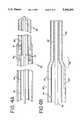
- FIG. 4ais a sectional view of an intermediate portion of the catheter assembly shown in FIG. 1.
- FIG. 4bis an alternative embodiment of the intermediate portion of the catheter assembly shown in FIG. 4a.
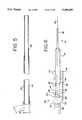
- FIG. 5is a cutaway view of the particle removal sheath portion of the catheter assembly shown in FIG. 1.
- FIG. 6is a cutaway view of the proximal end of the catheter assembly shown in FIG. 1.
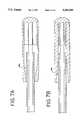
- FIGS. 7a and 7bdepict cutaway views of alternative embodiments of the proximal edge of the distal cap shown in FIG. 3.
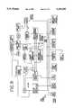
- FIG. 8is a flow chart of a preferred power control system (driving apparatus) for the system 10 of FIG. 1.
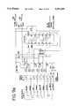
- FIGS. 9a to 9hare circuit diagrams for the power control system of FIG. 8.
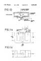
- FIG. 10is a axi-symetric cutaway view of a solenoid pole assembly (with an illustration of the flux path associated therewith) that forms part of the driving apparatus shown in FIG. 1.
- FIGS. 11a to 11dillustrate the steps associated with the construction of the pole shown in FIG. 10.
- FIG. 12is a graph illustrating the relationship between amplitude and frequency that establishes the operating threshold necessary to cause cavitation at the tip during intravascular operation.
- FIGS. 13a and 13bare graphs illustrating alternative driving waveforms which could be generated by the driving apparatus of FIG. 1 for operating the system.
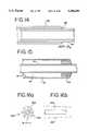
- FIG. 14is a sectional view of a distal portion of an exchange sheath that may be used in conjunction with the embodiment of FIG. 1.
- FIG. 15is a sectional view of an intermediate portion of the catheter assembly of an alternative embodiment of the present system that does not incorporate fluid particle removal.
- FIGS. 16a and 16bare cross sectional and longitudinal sectional views of an intermediate portion of the second tube of the catheter assembly of a further alternative embodiment of the present system that does not incorporate fluid particle removal.
- FIG. 17is a sectional view of a distal portion of the catheter assembly of FIG. 1 illustrating alternative embodiments of the profile of the end cap tip.
- FIGS. 18a and 18bdepict views of alternative embodiments of the distal cap.
- FIGS. 19a to 19cdepict alternative embodiments of the distal tip adapted for drug delivery.
- FIG. 20is a cross sectional view of an intermediate portion of the catheter assembly illustrating an alternative embodiment of the distal particle removal sheath support guide.
- FIG. 21is a cross sectional view of the proximal portion of the catheter assembly depicting an alternative embodiment of the mass-spring system.
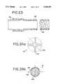
- FIG. 22is a cross sectional view of a distal portion of an alternative embodiment of the catheter assembly incorporating an inflatable dilation balloon.
- FIG. 23is a cross sectional view of an distal portion of an alternative embodiment of the second tube portion of the catheter assembly incorporating an expanding tip to facilitate exchange of intravascular devices.
- FIGS. 24a and 24bare cross sectional views depicting alternative embodiments of the core wire.
- FIG. 1there is illustrated a schematic representation of a system 10 according to a first embodiment of the present invention.
- the system 10provides for the intravascular delivery of mechanical energy as a therapy by itself or in conjunction with other intravascular therapeutic or diagnostic methods and systems.
- the quantity of energy delivered with this embodimentis preferably selectable by the user within a range extending from a quantity of energy sufficient to cause cavitation at a vessel site down to a quantity of energy less than the amount required to produce cavitation (e.g. a lower frequency and/or amplitude).
- the system 10includes a catheter assembly 14 with an energy delivery tip 16 and a driving apparatus 18.
- the system 10also includes a fluid particle removal system 20 including a pressurized fluid source 22 and a fluid discharge outlet 24.
- the catheter assembly 14has a working length of approximately 53.15 inches (135 cm) measured from the distal portion of a proximally-provided manifold to the distal tip 16.
- the catheter assembly 14will have a distal external profile in a range between 0.060 and 0.018 inches.
- the catheter assembly 14will have a distal external profile in a range between 0.04 and 0.010 inches. The following preferred embodiment will be described in terms of a catheter assembly 14 suitable for use in the peripheral vasculature.
- a catheter assembly for use in the coronary vasculaturemay be provided making corresponding adjustments to the dimensions provided in accordance with the ranges noted above.
- the catheter assembly 14has a distal portion 26 sized and adapted to be positioned intravascularly to a site in a patient's blood vessel at which treatment by application of low frequency mechanical energy or by creation of cavitation is to take place.
- the energy delivery tip 16is located at a distal end 28 of the catheter assembly distal portion 26.
- the vessel treatment sitemay be a location at which an obstruction by undesired material has been determined to be present. The presence and location of the undesired material may be diagnosed by angiographic methods (e.g. dyes) well known in the art.
- the undesired materialmay include plaque, stenosis, organized fibrotic, collagen, or atherosclerotic materials.
- a proximal portion 30 of the catheter assembly 14is adapted to be positioned outside of the body of the patient.
- the driving apparatus 18is associated with the proximal portion 30 of the catheter assembly 14 and is adapted to activate the delivery of low frequency mechanical energy from the tip 16 or for creation of cavitation at the tip 16.
- the catheter assembly 14is composed of a core wire 32 extending therethrough and connected to the tip 16 for the transmission of the energy from the proximal end of the catheter assembly to the distal end.
- the catheter assembly 14is also composed of a first tube 34 (also referred to herein as the wire support tube or the supply tube) and a second tube 36 (also referred to herein as the particle removal sheath or the damping sheath) which are coaxially disposed about the core wire 32.
- the core wire 32is adapted to move in oscillation axially within the first tube 34, as described in further detail below.
- the second tube 36is adapted to reduce or prevent transverse oscillation of the catheter assembly during oscillation of the core wire axially as well as provide additional functions as described further below.
- Support tubein general
- the support tube 34is adapted to support the core wire 32, maintain a pressure head through the catheter assembly, and reduce fluid flow losses while possessing a sufficiently low profile and flexibility for intravascular use.
- the support tube 34functions to provide a supporting path through which the core wire 32 can translate axially with minimal loss due to transverse vibration.
- the support tube 34provides for radial support for the axially translating core wire 32 from its proximal end to its distal connection to the tip 16.
- the support tube 34also provides an additional function.
- the support tube 34also provides an annular passage between the core wire 32 and the inner surface of the support tube 34 through which the pressurized fluid can flow distally to the tip.
- the annular clearance of the supply tube 34 around the core wire 32also determines the amount of flow loss through the system.
- the overall distal profile of the catheter assembly(including the supply tube) is constrained distally (i.e. corresponding approximately to the distal 35 cm) in order to provide intravascular access.
- the annular clearance between the core wire and the supply tubeis increased to its maximum allowable size to minimize flow losses through the proximal section of the catheter assembly while maintaining an overall low profile and support for the core wire.
- the maximum proximal profile of the catheter assemblyallows for an annular clearance outside of the catheter assembly for flushing of contrast fluid during a typical procedure when installed in a 7 or 8 French guide catheter.
- a manifold assembly 40associated with the proximal portion 30 of the catheter assembly 14 is a manifold assembly 40.
- the manifold assembly 40includes a first port 42 and a second port 44.
- the fluid source 22is adapted to provide fluid 41 (e.g. saline) under pressure to the first port 42 of the manifold assembly 40 via a supply line 43.
- the first tube 34is connected in a proximal portion thereof to the first port 42.
- the first tube 34extends distally from the first port 42 to the distal portion 26 of the catheter assembly 14 and proximally from the first port 42 to a proximal end 46 of the first tube 34. Hydraulic pressure is transmitted through the catheter assembly 14 via a first tube lumen 48 of the first tube 34 from the fluid source 22 to a distal end 50 of the first tube 34 and then to the tip 16.
- the first port 42is comprised of a T-block 52 placed in-line in the first tube 34 of the catheter assembly 14.
- the T-block 52may be a commercially available unit purchased from High Pressure Equipment Company, of Erie, Pa. Used in conjunction with the T-block 52 are nuts and glands 54 to form a fluid tight connection to the fluid supply line 43 from the fluid source 22.
- the T-block 52connects the fluid supply 22 to a first portion 58 of the supply tube 34 that extends proximally from the T-block and which is located within a spring bushing 60 and to a second portion 62 of the supply tube 34 that extends distally from the T-block and which is located within a wire support bushing 64. It is preferable that the T-block be readily connectable and disconnectable from the pressurized supply line 43 to facilitate use.
- the T-blockmay be manufactured as a custom unit.
- fluid pressureis directed both proximally and distally in the supply tube 34.
- the fluid 41moves distally in the lumen 48 of the supply tube 34 to the distal tip 16.
- the fluid 41enters the system under pressure (e.g. 1000 psi or less), as further explained below.
- the pressurized fluid 41is directed from a support tube distal opening 72 located at the distal end 50 of the supply tube 34 to the tip 16.
- the tip 16includes a tip channel 74 located internally thereto and open proximally to receive the pressurized fluid 41 and redirect it in a proximal direction.
- the support tube 34is comprised of sections along its length having different internal and external diameters.
- the support tube 34is provided with sections of different internal and external diameters to allow the flowing fluid medium 41 to retain more of its inherent pressure head by reducing flow losses due to resistance.
- the Darcy-Weisbach equationdemonstrates that as annular clearances are reduced, head loss is increased because the annular clearance is reduced and the fluid velocity is increased through the section to maintain flowrate.
- the diameter of the support tube 34is determined for operation at a given driving pressure.
- a step down in the diameter of the supply tube 34occurs at a location 76 approximately 100 cm distally from the distal end of the second port 44 of the catheter assembly.
- this step downis accomplished by forming the support tube of separate sections 78 and 80 fitted into each other and lap soldered together.
- the inner diameter of the support tube proximal section 78is 0.026 inches.
- the inner diameter of the support tube distal section 80is 0.013 inches.
- the outer diameter of the support tube proximal section 78is a constant 0.036 inches. In the distal section 80 of the wire support tube 34, the outer diameter varies.
- the distal wire support tube outer diameteris 0.025 inches for the first 3.9 inches distally from location 76. Then, the outer diameter of the distal support tube section 80 tapers linearly for 2 inches down to a finished outer diameter of 0.017 inches. In this most distal portion of the wire support tube 34, the wire support tube wall is 0.002 inches thick to provide a desired degree of flexibility and supply pressure.
- a bushing 81is positioned between the distal and proximal sections at the connection location 76.
- the proximal and distal sections 78 and 80 of the wire support tubeare formed of separate pieces soldered together, however alternatively, a necked tubing would be preferred.
- the preferred necked configurationis illustrated in FIG. 4b.
- the support tube 34would be formed of a single piece of tubing having dimensions corresponding to those of the proximal section 78' and processed, for example by necking, to form the distal section 80' distally of the tapering location 76'.
- a necked configurationwould provide a smoother flow path transition through the catheter assembly thereby reducing flow losses.
- the supply tube dimensionsare selected in part to provide a specific preferred annular clearance between the inner wall of the supply tube 34 and the core wire 32.
- the annular clearance between the core wire 32 and the first tube 34is selected in part to optimize effective performance through various bends that the catheter assembly 14 will undergo during intravascular use.
- the annular clearanceis 0.0025 inches in a distal portion and 0.005 inches in a proximal portion. Alternative clearances may be appropriate.
- the support tube 34is fabricated of 304 stainless steel although other materials including non-metals having similar properties may also be used.
- the support tubecould be fabricated using fiber composite technology, i.e. the tube could be formed of composite filaments captured in a resin or polymer. Such a construction could increase device pushability, hoop strength, and support to the core wire.
- particle removal ports 82 and 84are provided in both sections 78 and 80, respectively, of the wire support tube 34. These ports 82 and 84 route the fluid 41 back into the particle removal sheath 36. This redirection by the particle removal ports 82 and 84 allows the kinetic energy of the fluid 41 to become the driving pressure for pushing the fluid and any particulate broken away from the vessel obstruction back to the manifold exhaust port 44.
- two sets of portsare incorporated to provide a two stage drawing capability. Primary particle removal is provided by the proximal ports 82 and secondary routing or particle removal initiation is provided by the distal ports 84.
- the proximal ports 82each have a diameter of 0.010 ⁇ 0.005 inches and the distal ports 84 each have a diameter of 0.003 ⁇ 0.002 inches.
- distal fluid dispersion orifices 85may be provided.
- the dispersion orifices 85would be located proximal to the proximal end of the distal tip 16 at which the redirected fluid exits the distal tip.
- the dispersion orifices 85would be formed to direct fluid normal or slightly proximal to the distal tip axis.
- the orifices 85would be located around the periphery of the supply tube 34.
- the orifice or port sizeis determined so that a flow balance would be maintained in the artery, thereby preventing collapse of the artery due to a pressure vacuum.
- the dispersion orifices 85 portsare preferably situated around the periphery of the supply tube 34 so that the proximally directed fluid flow out of the distal tip 16 would be disrupted in select locations corresponding to the locations of the dispersion orifices, but would remain uninterrupted in the locations between adjacent dispersion orifices in order to maintain the particle removal flow path.
- the second port 44 of the manifold assembly 40provides the outlet for the discharge of fluid effluent and any particulate attached viscously therein.
- the second tube 36(also referred to as the particle removal or damping sheath) is connected at a proximal end 86 thereof to the second port 44.
- the particle removal sheath 36extends distally from the second port 44 to the distal portion 26 of the catheter assembly 14.
- the fluid 41is withdrawn from the catheter assembly 14 via a particle removal sheath lumen 88 of the particle removal sheath 36.
- the particle removal sheath 36extends from the second port 44 to a distal particle removal sheath opening 90 at the distal end 26 of the catheter assembly 14.
- the particle removal sheath distal opening 90is located adjacent to the channel 74 of the tip 16, and specifically the particle removal sheath distal opening 90 is located just immediately proximal of the tip channel 74.
- the particle removal sheath 36functions to receive and withdraw fluid 41 and any material attached viscously therein from the area at the particle removal sheath distal opening 90.
- the particle removal sheath 36withdraws the fluid 41 supplied via the supply tube 34 that is directed at and redirected by the tip 16.
- the particle removal sheath 36functions to draw particles or material, if any, that may become broken off from the undesired material of the vessel obstruction being treated by the application of energy from the distal tip to the vessel site.
- the supply tube 34is located in the particle removal sheath lumen 88 and is sized to occupy only a portion of the particle removal sheath lumen 88, thereby providing an annular region sufficient to accommodate withdrawal of fluid 41 via the particle removal sheath lumen 88.
- the particle removal sheath distal opening 90is formed by the annular region 92 at the distal end of the particle removal sheath 36 between the inside of the particle removal sheath 36 and the outside of the first (or supply) tube 34.
- the particle removal sheath 36terminates proximally at the second port 44.
- the second port 24is provided by a Y-manifold 96 connected to the proximal end of the particle removal sheath 36. Inside the Y-manifold 96, the particle removal sheath 36 terminates distal to an O-ring compression seal 98 on the wire support tube 34. The O-ring 98 is retained in the Y-manifold 96 by a compression nut 100.
- the second port 44exhausts the withdrawn effluent to a collection pump (not shown) which provides positive pressure or vacuum.
- the particle removal sheath 36is provided with dimensions to provide for fluid dynamics similar to those of the wire support tube 34 but with substantially lower flow losses through its length.
- the particle removal sheath 36is formed of a first section 102 connected to the Y-manifold 96.
- the particle removal sheath 36may be connected to the Y-manifold 96 by a urethane bond.
- the particle removal sheath first section 102is 39.8 inches (101 cm) long and has an inner diameter of 0.042 inches and an outer diameter of 0.052 inches.
- the particle removal sheath first section 102connects to a particle removal sheath second section 104.
- a second section 104fits into the first section 102 and extends 13.4 inches (33.9 cm) distally therefrom.
- the first and second sections 102 and 104may be connected by a urethane bond.
- the particle removal sheath 36can also be formed of one piece of tubing and necked or otherwise processed to produce the desired change in profile in a manner similar to that described above with respect to the supply tube and depicted in FIG. 4b).
- the overall length of the particle removal sheath 36 from the distal end of the Y-manifold 96 to the distal end thereofis 53.1 inches.
- the particle removal sheathis formed of a single piece of tubing necked to provide the first and second portions 102' and 104' as shown in FIG. 4b.
- the proximal portion 102'has a length of 101 cm with an outer diameter of 0.052 inches and an inner diameter of 0.042 inches.
- the particle removal sheath second section 104'has a length of 34 cm with an outer diameter of 0.035 inches and an inner diameter of 0.029 inches.
- the second tubemay be formed of more than one piece of material and connected together to provide the change in inner and outer diameters, as described above. Such a construction is illustrated in FIGS. 4a and 5.
- the piecescould be connected together by suitable means such as a urethane bond. Additional lengths of tubing may be provided for the purpose of forming an overlapping bond between such separate pieces. An additional length may be provided to connect the proximal end of the second tube into the Y-manifold. In addition, it may be desired to provide the second tube with additional changes in profile to contribute the fluid characteristics, damping, etc.
- the distal and proximal sections of the particle removal sheath 36provide essentially similar functions. Like the supply tube 34, the inner and outer diameters of the particle removal sheath 36 are sized based on fluid dynamic analysis for minimizing pressure drop through each section or portion of the particle removal sheath.
- the particle removal sheath 36is also provided with sufficient annular stiffness to prevent collapsing during particle removal flow. A necking process may be used in the construction of the particle removal sheath second section 104 to provide for reduction in diameter and wall thicknesses.
- the outer diameter of the distal portion 104 of the particle removal sheathis equal to or less than the outer diameter of the oscillating distal tip 16 to prevent catching of the distal end 90 of the particle removal sheath 36 on lesion material as the tip 16 advances therethrough.
- the particle removal sheath 36in a present embodiment, is constructed from a high density polyethylene (HDPE).
- HDPEpossesses properties considered to be desirable for use as a material for the particle removal sheath. These properties include relatively high stiffness and low coefficient of friction.
- Other materials for the damping sheathmay be used including other plastics or even metals, such as stainless steel or a combination of metal(s) and non-metals, e.g. a composite such as a braided configuration.
- the damping sheathcould be fabricated using fiber composite technology, i.e. the tube could be formed of composite filaments captured in a resin or polymer. Such a construction could increase device pushability, hoop strength, and support.
- the particle removal sheath 36be maintained concentrically disposed about the supply tube 34. Accordingly, a sheath guide 112 may be used.
- the sheath guide 112retains the concentricity of the particle removal sheath 36 around the distal supply tube 34. This has the advantage of preventing any side spray or diffusion of the operating fluid 41 when it is redirected proximally into the distal opening 92 due to the particle removal sheath 36 becoming eccentric.
- the sheath guide 112is fabricated from radially expanding leaf springs which provide a radial force in an axis-symmetric fashion to produce the proper centering effect.
- a deflector 114is provided to additionally support redirection of the fluid leaving the proximal exhaust port 82.
- the deflector 114reduces or prevents dispersal when the fluid impacts the inner wall of the particle removal sheath 36.
- the deflectoris formed of a tapered piece of stainless steel to reduce flow losses therearound.
- the particle removal sheath or second tube 36also acts as a damping sheath to reduce or prevent the generation of transverse waves when the core wire 32 is driven in translation.
- the second tube 36provides this damping function by providing a frequency dependent stiffness to the catheter assembly. Based on the damping coefficient of the material, the force exerted by the particle removal sheath 36 on the core wire 32 is increased as frequency goes up.
- the reaction forcefollows the following relationship:
- the velocity component in the above equationis determined by the operating frequency of the system. As the velocity is increased, the restraining force is increased linearly. The velocity is the relative velocity between the sheath 36 and the wire support tube 34.
- the return effluent occupying the region between the support tube 34 and the particle removal sheathserves the function of a damping layer.
- alternative materialsmay be used to provide for the damping function, as described further below.
- the catheter assembly 14also includes the core wire 32. extending therethrough.
- the core wire 32is connected at its distal end to the tip 16 and extends from the tip 16 proximally through the first tube lumen 48 of the catheter assembly 14 to the proximal end 30 thereof.
- the core wire 32is sized to occupy only a portion of the first tube lumen 48 thereby allowing an annular region sufficient to accommodate delivery of fluid 41 via the first tube lumen 48 in the annular region.
- the supply tube distal opening 72is formed by the annular region at the distal end 50 of the first tube lumen 48 between the inside of the first tube lumen 48 and the core wire 32.
- the core wire 32provides the function of transmitting physical displacement from the proximal end 30 of the catheter assembly 14 to the distal portion 26 and specifically to the tip 16.
- the transmittancemay be accomplished by translation and/or elongation of the core wire 32. In a preferred embodiment, the transmittance is accomplished primarily by translation and secondarily by elongation.
- the core wire 32is preferably of a biocompatible material possessing a high tensile strength and a high endurance limit. In a present embodiment, high tensile strength stainless steel 304 wire is used. In a present embodiment, the wire used possesses a tensile strength of approximately 300-400 kpsi.
- a commercially available wirehaving a trade name of HYTEN stainless steel wire and produced by Fort Wayne Metal Products, Fort Wayne, Ind.
- the preferred diameter of the core wireis approximately 0.008 inches, although a wire in the range between 0.005 and 0.010 inches is also considered acceptable.
- Alternate materials having similar propertiesmay be used for construction of the core wire such as titanium or titanium alloy.
- the core wiremay be provided with a larger profile in its proximal portion and a smaller profile in its distal portion. This may be accomplished by providing a core wire with a tapered profile or a profile that is stepped or a combination thereof.
- the core wirepreferably has a small profile distally for increased flexibility in the distal section. Since the catheter assembly is intended for both peripheral and coronary applications, distal flexibility is important.
- the profile of the proximal portion of the core wireis enhanced by the addition of a stainless steel hypotube positioned on the proximal portion of the core wire. The stainless steel hypotube extends over the proximal 39.4 inches of the core wire.
- the stainless steel hypotubehas an outer diameter of 0.015 inches and an inner diameter slightly larger than the diameter of the core wire 32 (i.e. 0.008 inches).
- the core wire and the hypotubeare soldered together so that the effective outer diameter of the core wire in the proximal portion (extending over the proximal 42 inches) is 0.015 inches.
- the core wire diameter distal of the hypotubeis the diameter of the core wire only, i.e. 0.008 inches.
- the core wiremay be formed of a single piece of wire that is necked down, ground, or otherwise processed to reduce the diameter thereof in a distal portion.
- stainless steel or high tensile strength composite fiber coilsmay be incorporated to the core wire to improve its pushability while retaining flexibility.
- the core wireis coated with a Teflon coating to reduce friction between the wire support tube 34 and the core wire 32.
- the Teflon coatingalso contributes to damping of the core wire during oscillation.
- Other coatings providing low frictionmay be substituted or used.
- meansmay be incorporated into the core wire or in the construction thereof, to enhance the resiliency of the core wire.
- the core wirecan be processed with a stress relieving heat treatment for this purpose.
- FIG. 6there is depicted a most proximal portion 120 of the catheter assembly 14 including the proximal end 46 of the supply tube 34.
- the driving apparatus 18(as shown in FIG. 1) imparts movement to the core wire 32 by means of generating an alternating magnetic field that operates on a mass 122 connected to a proximal end 124 of the core wire 32.
- the proximal end 46 of the supply tube 34 of the catheter assembly 14includes a pressure vessel housing 126 having therein a cylindrically shaped housing chamber 128.
- the mass 122is located in the chamber 128.
- a spring 130is adapted to cooperate with the mass 122 and the core wire 32 to form a mass-spring assembly 132, as explained in more detail below.
- the spring 130is also located in the housing chamber 128.
- the chamber 128is sized to accommodate the axial oscillation of the mass 122 therein. In this embodiment, the chamber 128 is approximately 1.5 inches in length.
- the driving apparatus 18generates a magnetic field through the housing 126 that operates on the mass-spring assembly 132.
- the housing 126includes an outer sleeve portion 134 and an outer sleeve bushing portion 136.
- the outer sleeve portion 134provides a bearing surface for the magnetic mass 122, isolation between the magnetic mass 122 and the magnetic poles of the driving apparatus 18, and field coupling of the mass (saturation switch), as explained below.
- the inside diameter of the outer sleeve portion 134is sized to closely fit to the dimensions of the mass 122. In the present embodiment, the internal diameter of the sleeve portion 134 is 0.210 inches and the external diameter of the mass 122 is 0.200 inches. Thus, in the present embodiment, the radial clearance between the sleeve portion 134 and the mass 122 is 0.005 inches. This clearance gap dimension is determined to provide for efficient transmission of the magnetic field across the gap to the mass 122.
- the outer sleeve portion 134is preferably fabricated from a magnetic material possessing a high permeability and saturation point. In a preferred embodiment, a mild steel is used. Alternatively, stainless steel 416 or other similar materials may be used.
- a magnetic materialallows the flux path from the poles of the driving apparatus 18 to be essentially shunted until the sleeve becomes saturated and the flux is forced through the mass 122. At the time of saturation, the flux is dumped into the mass causing a switch effect on the force level on the mass 122, essentially providing an almost square function forcing curve on the mass 122 which is a desirable result.
- the housing 126also includes a threaded stud 138.
- the threaded stud 138is included on an outside proximal end of the sleeve portion 134.
- the stud 138functions to provide for tuning of the catheter assembly 14.
- the sleeve portion 134is positioned and received into the driving assembly 18, as explained in more detail below.
- the threaded stud 138Through the use of the threaded stud 138, the position of the magnetic mass relative to the driving apparatus solenoid poles can be adjusted to provide the desired driving performance. It is preferred that the stud 138 be adjusted to provide maximum displacement of the magnetic mass 122 induced by the magnetic field. Adjustment of the driving apparatus 18 during operation will be further described below.
- the housing 126also includes the outer sleeve bushing portion 136.
- the outer sleeve bushing portion 136forms the distal portion of the housing 126 and defines the distal wall of the housing chamber 128.
- the outer sleeve bushing portion 136fits into an open distal side of the outer sleeve housing portion 134 and includes a shoulder 142 that rests thereupon.
- the sleeve bushing portion 136is cylindrically shaped and approximately 0.475 inches in length with the shoulder portion 142 being approximately 0.375 inches long.
- the outside diameteris sized and adapted to closely fit into the outer sleeve housing portion 134.
- the outer sleeve bushing portion 136also defines a cylindrically shaped opening therethrough to receive the spring bushing 60.
- the outer sleeve bushing portion 136provides annular spacing between the outer sleeve portion 134 and the spring bushing 60.
- the outer spring bushing portion 136provides for coaxial assembly of the outer sleeve portion 134 and the spring bushing 60.
- the sleeve bushing portion 136is fabricated from 302 stainless steel and is attached to the outer sleeve portion 134 by means of soldering. Alternative materials and alternative means of connection may be suitable.
- the spring bushing 60is mounted in the outer sleeve bushing portion 136.
- the spring bushing 60is cylindrically shaped and approximately 3 inches long and has an outside diameter of approximately 0.125 inches.
- the spring bushing 60defines a cylindrically shaped opening therethrough to receive the proximal portion of the first (or supply) tube 34.
- a proximal end 144 of the spring bushing 60provides a mounting surface for a distal end of the spring 130.
- the spring bushing 60also provides support to the proximal portion of the supply tube 34 that is received in the opening therein.
- the spring bushing 60is fabricated from 302 stainless steel. Alternatively, other similar materials may be used.
- the spring bushing 60is soldered to the outer sleeve bushing 136 and the proximal portion of the supply tube 34.
- the mass 122 and the spring 130are designed to operate together as the mass-spring assembly 132 in conjunction with the driving apparatus 18 to impart the desired oscillation to the wire 32. Therefore, the spring-mass assembly 132 provides for both magnetic circuit coupling of force inducement from the driving apparatus 18 and dynamic inertia for conversion of the spring's potential energy to kinetic energy.
- the mass 122is formed of a cylindrically shaped magnetic metal. In a present embodiment, the mass 122 is made of mild steel. This material possesses both desired properties of high magnetic permeability and a high magnetic saturation point material.
- the mass 122has a cylindrically shaped recess 146 located therein and oriented in a distal direction to receive the proximal portion of the spring 130.
- the mass 122has an outside diameter of 0.200 inches and an internal blind diameter of 0.180 inches.
- the mass 122includes a 0.025 inch center hole for core wire attachment and four peripheral holes (not shown) coaxial therethrough. These latter holes function to improve fluid dynamic flow (whether air or water) around the mass 122.
- the spring 130is connected to the mass 122 inside of the housing 126.
- the spring 130provides energy storage for the system 10.
- the magnetic field generated by the driving apparatus 18moves the mass 122 proximally. Movement of the mass 122 proximally continues until the dynamic and static forces on the mass 122 are offset by the spring's reaction force due to its attachment to the mass 122 and the spring bushing 60 (i.e. the "reference point" of the system).
- a "music" wirehigh tensile strength steel
- the wound springhas an outside diameter of 0.180 inches overall.
- the spring 130is preferably fabricated from a material having magnetic properties to contribute to the forcing function applied by the driving apparatus 18 to the magnetic mass.
- the spring 130is composed of wire having a diameter of 0.032 inches.
- the spring 130is soldered to both the mass 122 and the spring bushing 60.
- the mass 122includes the cylindrically shaped recess 146 located therein and oriented in a distal direction to receive the proximal portion of the spring 130.
- the mass recess 146is preferably partially filled with solder so that some of the proximal spring coils received in the mass recess 146 are fixed, i.e. not active.
- four spring coils between the mass 122 and the spring bushing 60are allowed to remain active, that is, allowed to move during mass oscillation.
- the distal tip 16is connected to the distal end of the core wire 32.
- the distal tip 16includes a distal cap 150 and a distal bushing 152.
- the cap 150 and bushing 152are soldered to the core wire 32 for transmission of the core wire movement.
- the end tip 16has a distal surface 154 which may possesses a spherical profile, or an other than spherical profile as discussed below.
- the end cap 150extends proximally from the distal bushing 152.
- the end cap 150has an inner diameter large enough to accommodate the distal portion and end 50 of the first tube 34 as well as to provide an annular region between the first tube 34 and an inside surface of the end cap 150.
- the end cap 150possesses a length such that a proximal end 158 of the end cap 150 is proximal of the distal end 50 of the first tube 34 and distal of the opening 90 of the particle removal sheath 36.
- the end cap 150has an outer diameter of 0.036 inches, an inner diameter of 0.018 inches, and has a length of approximately 0.200 inches.
- the proximal end 158 of the end cap 150is spaced from the opening 90 of the particle removal tube 36 by approximately 0.05 inches during operation. This distance will change of course when the tip is oscillating axially. This distance may also be changed to modify the flow pattern of particulate around the tip.
- the outside proximal region of the distal cap 150is tapered to reduce potential for catching of the proximal edge of the cap on the arterial obstructions during tip oscillation. This tapering 160 may be accomplished through grinding or chemical etching. A taper of approximately 10 degrees is presently used.
- the end cap 150is made of 304 stainless steel.
- solder joint 162Located inside the end cap 150 and extending proximally from the end cap tip 122 is a solder joint 162.
- the solder joint 162surrounds a most distal portion of the core wire 32 and bonds the core wire to the end cap 150.
- the core wire 32, a proximal end of the bushing 152 and the end cap 150define the channel 74 that receives the supply of fluid 41 from the first tube 34 and redirects it proximally.
- the redirected fluid 41 and viscously attached materialare withdrawn from the vascular site via the distal particle removal sheath opening 90.
- the end cap solder joint 162 and the bushing 152occupy approximately 0.05 inches of the end cap 150.
- the end cap solder joint 162is a silver solder compatible with 304 stainless steel and used following generally accepted soldering practices.
- the inside proximal surface 164 of the end cap 150can be modified to possess exit flow characteristics to improve particle removal performance.
- the present embodimentutilizes a straight taper for the proximal inside surface 164.
- the inside surface 164can have a reducing taper.
- an inside surface 166may possess an expanding taper, as illustrated in FIG. 7b. All the taper configurations can be fabricated into the tip using conventional machining processes and deburred with a chemical etch process.
- the driving apparatus 18is located at and associated with the proximal portion 30 of the catheter assembly 14.
- the driving apparatus 18is adapted to impart axial movement (i.e. transmittance) to the core wire 32 located in the catheter assembly 14.
- the driving apparatus 18is specifically adapted to impart a proximally directed force on the core wire 32 which causes oscillation of the core wire due to the action of the spring 130 at the proximal portion of the core wire 32.
- the driving apparatus 18can be operated to impart a proximally directed (tensioning) force on the core wire while the pressurized fluid 41 imparts a tensioning force upon the tip 16 to move it distally.
- the bushingreceives a fluid force that cooperates with the proximal mass-spring assembly 132 to provide for oscillation of the core wire 32.
- the core wire 32is connected at a proximal end 124 thereof to the mass 122.
- the driving apparatus 18is adapted to apply its force to the mass 122 of the core wire 32 at a frequency, thereby causing the entire core wire 32, and the tip 16 connected at the distal end thereof, to move in oscillation axially.
- the frequency and amplitude of the core wire movementis selected to deliver energy to the site at the distal end of the catheter assembly 14, and specifically proximate to the tip 16, for the break up and/or removal of undesired material.
- the driving apparatus 18is comprised of a power control system 168 connected to a driving solenoid 169.
- the power control systemis comprised of a Peavy CS-800 stereo power amplifier, a BK Precision Model No. 3011B 2 MHz function generator, a Fluke Model No. 77 multimeter, and miscellaneous coaxial cables to route the function generator signal to the amplifier then route the output of the amplifier to the driving solenoid through the multimeter for current monitoring.
- the driving solenoidis sized to receive the proximal end of the catheter assembly 14 and specifically, the housing 126 containing the spring mass system 132.
- FIG. 8Circuit diagrams for the power control system shown in FIG. 8 are shown in FIGS. 9a to 9h.
- the power control systemincludes an emergency power control circuit (FIG. 9b), a solenoid hook up circuit (FIG. 9c), a square wave generator circuit (FIG. 9d), a foot control switch circuit (FIG. 9e), a high frequency switch (FIG. 9f), a peak current display circuit (FIG. 9g), and a frequency display circuit (FIG. 9h).
- the power control systemincludes an emergency power control circuit (FIG. 9b), a solenoid hook up circuit (FIG. 9c), a square wave generator circuit (FIG. 9d), a foot control switch circuit (FIG. 9e), a high frequency switch (FIG. 9f), a peak current display circuit (FIG. 9g), and a frequency display circuit (FIG. 9h).
- the driving solenoidis comprised of a pair of solenoid poles. Referring to FIG. 10, there is depicted a solenoid pole 170 which can be used for the driving solenoid.
- the polesare symmetrical and constructed from four U-shaped transformer core assemblies.
- the core assemblyis commercially available from Electro-Core, Washington, Mo., Part Number EL-1005.
- the coresare constructed by laminating thin magnetic steel layers together to produce a highly permeable core which posses a high saturation point and low eddy current losses (due to lamination construction).
- FIGS. 11a to 11dThe processing steps for construction of the pole pieces and solenoid coil are represented in FIGS. 11a to 11d.
- the faces 172 of the pole piecesare tapered to channel the magnetic flux 174 through the proximal mass thereby improving magnetic coupling with the mass 122. Tapering the pole faces 172 also reduces flux losses across a gap area 176 between the pole faces 172.
- the gap 176 between the pole facesis 0.05 inches. This dimension influences the force transferred to the mass 122. Increasing the size of the gap 176 would reduce the force transferred to the mass 122 and thereby result in a decrease of tip displacement; reducing the gap 176 decreases the available mass travel, again resulting in a reduction in tip displacement.
- the solenoidhas a body and tuning knob and/or stop, an inner diameter of 0.25 inches to receive the housing 126, and a length of 2.00 inches.
- the driving solenoidrequires approximately 200 watts of power at 8 amps.
- control and operation of the catheter assembly 14is effected from the proximal portion 24 located outside of the patient's body.
- Operation of the system to treat an obstruction at a vessel siteinvolves positioning of the distal portion 26 of the catheter assembly 14 into the patient's vasculature. Positioning may be effected by means and methods which are known to those having skill in the art.
- the catheter assembly 14may be positioned percutaneously into the vascular system from an accessible location such as the femoral artery. The positioning of the catheter assembly can be accomplished conventionally through the use of a guide catheter which has been already prepositioned to the obstructed vessel site through the use of a guide wire.
- the distal portion of the wire support tube 34may be formed or bent by the physician-clinician into a slight curvature to allow steering of the tip 16 according to conventional methods known and used with conventional guide wires for intravascular positioning.
- a slight ⁇ J ⁇can be formed in any variety of radii and locations proximal from the end 16 provided that the bending or curve is at most one inch from the distal tip and that the bend radius is no less than 0.375 inches.
- the clinician-physiciancan operate the driving apparatus 18 to impart mechanical energy from the tip 16 by oscillating the core wire with the desired stroke, frequency and power.
- the driving apparatus 18is operated to impart axial movement to the proximal portion of the core wire 32.
- the operating frequency of the tip 16is determined by the operating frequency of the driving apparatus 18.
- the operating frequency of the systemis a function of the system's stiffness (proximal spring stiffness), system mass (proximal mass and core wire), and/or system damping (wire support tube annulus material and clearances).
- the most influential component defining the system operational frequencyis the system stiffness.
- materialsare selected and processed to provide the appropriate stiffness for the frequency of operation desired.
- the operating frequencycan be established at the desired level. In the present embodiment, the operating frequency can be established any point in a range of 100 to 5000 Hz or less.
- Tip displacementis a factor in determining a preferred operating frequency for the system.
- An operating frequency and tip displacement amplitudeare preferably selected to yield a tip velocity suitable to recanalize the vessel obstruction by reorganizing the obstructive material or at least temporarily displacing it.
- the frequency and amplitudeare selected to cause cavitation at the tip.
- Cavitationis favored as a method of disrupting the cellular structure of the obstructive material in the vessel. Studies indicate cavitation generates a tissue dependent disruption, i.e. hard calcified lesions break up readily under low power levels while more compliant healthy arterial tissue remain intact.
- a preferred operating frequency of the systemis 540 Hz with a tip a peak to peak displacement of 0.100 inches.
- the operating frequencyis proportional to stiffness and inversely proportional to system mass and damping, if a higher frequency is preferred, this can readily be provided by either increasing the stiffness of the spring or decreasing the system mass and damping.
- the peak-to-peak displacement of the tip 16 oscillationcan be adjusted down from approximately 0.100 to 0 inches.
- the driving system waveformIn addition to driving frequency and amplitude, another consideration in control system operation and performance relates to the driving system waveform.
- the mass 122In the operation of the driving apparatus 18 to oscillate the core wire 32, it is advantageous to minimize the magnetic resistance of the magnetic circuit. Accordingly, the mass 122 is drawn into the center of the magnetic pole gap 176 (of FIG. 10). As the mass 122 is moved from its rest position, a reaction force is generated on the mass by the spring 130. Upon reaching pole center, the magnetic field is removed or shut off and the spring 130 attempts to restore the mass 122 to the rest position.
- the magnetic fieldThrough the use of digital control in the power circuit of FIG. 8, the magnetic field is energized at a frequency at or below the system's mechanical natural frequency. The process of pulling the mass proximally is repeated at this operating frequency. In one embodiment of operation, this process repeats itself at a frequency of 540 times per second.
- the driving apparatus 18 and the power sinusoid excitation wave formallows the system to be driven with an electrical
- the driving signalincludes a series of pulses with each pulse having a relatively high initial spike to impart rapid current increase in the coil of the solenoid.
- the high initial spikeis followed by a flat pulse.
- each pulsemay also include a relatively sharp reverse spike at the end of the pulse to shut off the solenoid force.
- the waveform depicted in the graph of FIG. 13bis another alternative embodiment of the operating mode.
- the embodiment of FIG. 13bshows a driving circuit output signal with a square wave.
- a force on the proximal end of the core wire to move it distallyis provided by the recoil action of the spring in cooperation with the operation of the magnetic oscillation of the proximal mass.
- a sinusoidal wave formis preferred.
- the driving apparatuscould be operated to move the core wire in a distal direction by application of force on the proximal portion of the wire, instead of relying upon the reaction by the spring to move the core wire distally.
- the driving apparatus and the springcould combine to move the core wire distally.
- a distal forcemay be applied by a combination of both the spring 130 and the driving apparatus.
- the systemDuring normal operation of the driving apparatus 18 to impart axial oscillation to the core wire and tip, the system generates an audible sound that is loudest during maximum tip displacement. This coincides with maximum energy delivery to the site of the vessel obstruction. In a preferred mode of operation, the system 10 should be operated at maximum tip displacement to deliver the maximum quantity of energy to the vessel site. Because the system is relatively quiet during operation, the audible feedback from the system may be obscured by ambient noise levels in a typical catheter lab. As a means of providing tip displacement feedback, an audio output from the solenoid is preferably incorporated into the system. The physics of operation of the solenoid produce a variance in the solenoid current requirements as the proximal mass 122 moves through the magnetic gap. Using this current level fluctuation as a control to monitor the oscillation of the proximal mass in the gap and similarly the displacement of the distal tip, a tone signal can be generated whose tone or level would represent tip displacement levels.
- An alternate method of displacement monitoringwould be to mount a small vibration pickup, similar to a phonographic needle, on the wire support tube 34 and monitor the distal tip energy directly and calibrate its output to tip displacement. Again the pickup's output would be routed to an audio amplifier for generation of a tone which would indicate an acceptable tip displacement.
- a means for fluid particle removal from the site of the vessel obstruction proximate to the distal tip 16provides for the removal of particles, such as particles of the undesired material that break away upon application of low frequency mechanical energy or cavitation.
- This functionis provided in part by the flushing action of pressurized fluid 41 as it is applied to the distal tip from the first (or supply) tube 34 and withdrawn by the particle removal sheath 36.
- This fluid removal actionutilizes at least in part the Coanda effect.
- the fluidis supplied under pressure to the manifold assembly 42 by the hydraulic pressure source 22.
- the hydraulic pressure source 22is a supply pump that delivers saline fluid at an output rate of up to 200 mL/minute at a pressure that is variable at approximately 1 kpsi or less.
- the fluidfills the supply tube 34 including the pressure chamber 128 of the housing 126.
- pressurized fluid 41escapes the supply tube 34 at the distal opening 72 and is directed at the distal tip 16.
- the location of the particle removal sheath 36 relative to the distal tip 16is important for proper particle removal flow performance around the distal tip 16.
- the distal end of the particle removal sheath 36is 0.05 inches from the proximal edge 158 of the distal cap 150 during operation.
- the particle removal sheathmay be moved relative to the supply tube 34. Movement of the particle removal sheath 36 from the preferred position relative to the supply tube 34 reduces the particle removal effect.
- the system 10 with fluid particle removaloperates with a preferred inlet 42 pressure of 1000 psi or less.
- This operating pointhas been defined by using conventional fluid dynamic relations with preferred geometries in order to attain a mild particle removal effect at the device distal tip.
- the operating pressurecan be increased or decreased based upon the desired particle removal effect. Increasing the pressure results in higher particle removal and more turbulence around the distal tip 16. Conversely, decreasing the operating pressure reduces the amount and severity of particle removal.
- the operating pressureis also influenced by the core wire 32 and supply tube 34. If a core wire of a larger dimension is used with a supply tube 34 having the same internal diameter, the required supply pressure increases in order to obtain the same distal exit pressure. The opposite is also true, as the wire size is reduced supply pressure requirements drop.
- the operational pressurecan vary from 500 to 1 kpsi or less.
- a vacuumcould be applied to the second port 44 to reduce the proximal supply pressure requirements while maintaining the same pressure differential between the supply and particle removal ports.
- the proximal supply pressure requirementwould be reduced to less than 1 kpsi, for example.
- Application of a proximal vacuumcould require a change in the construction of the particulate transmission sheath 36.
- the sheath 36would be required to support a high hoop stress and therefore a construction of a hypotube or composite construction may be preferred.
- obstruction ablationwould be accomplished with the distal tip mechanical movement and a distal orifice.
- Particulate transmission proximallywould be accomplished through the combined efforts of the vacuum and distal return orifices.
- salineis the preferred fluid 41 of operation. Saline passes the low viscosity and bio-compatibility required for the system operation.
- a lower viscosity, bio-compatible fluidcould be used.
- a gassuch as CO 2 could be used. If CO 2 were used, it would be important to recover 100% of any CO 2 gas input to the system along with any additional fluid attached viscously.
- the gassuch as CO 2 , should be bio-diffusible (i.e., quickly absorbed into the blood stream).
- the gasmay be routed through a lubricating reservoir to promote a lubricated wire/support tube interface. Use of a gas may require a tightly controlled distal cap having a proximal annular edge to promote the Coanda effect for flow attachment to the distal wire support tube 34.
- the present embodimentutilizes two modes of energy transfer for particulate retrieval and removal.
- the first inherent form of energy into the systemis a relatively low velocity, static pressure head flow through the fluid from the hydraulic supply pump 22. As the fluid 41 moves through the system, this low velocity and static pressure is exchanged for a high velocity, low static pressure head energy at the proximal and distal particle removal ports.
- the portsact as a means of converting any potential head or static head to a kinetic head or velocity head. This conversion to velocity promotes viscous attachment of surrounding particles into the supply fluid and their movement distally with the operating fluid. This viscous attachment yields the distal particle removal zone around the distal tip of the device. As the operating fluid moves proximally, the kinetic head is converted back to a static head pushing the fluid proximally.
- the supply fluid 41is stopped during tip oscillation.
- the fluid 41can act as a hydraulic damper during supply flow thereby impeding tip oscillation.
- the fluid supplymay be modulated such that the fluid is supplied at times corresponding to when the driving apparatus is off.
- This modulation of fluid supplycan be accomplished using a manual valve activated either by hand, pneumatics, or electronics to turn the flow on and the magnetic circuit off.
- the modulationcould also be accomplished by an electronic controlling circuit which essentially controls the frequency at which the fluid is turned on and off in sequence with the driving apparatus. Present valved technology would limit the operating frequency of this fluid modulation.
- Frequencies attainable today at pressuresvary from low (less than 1 Hz) using a manual valve to very high (up to 1 Khz) using a bobbin type valve.
- the fluid supplycould be modulated by a solenoid.
- the fluid modulation solenoidcould be continually on and distal mass oscillation would begin when the fluid flow was halted.
- pressure to balloon during inflationcould be modulated to provide a low frequency (0-1000 Hz) balloon profile oscillation.
- the catheter assembly 14can be exchanged for another, if desired, or for a separate different intravascular device.
- an exchange sheath 180may be utilized, as illustrated in FIG. 14. The exchange sheath 180 would be positioned over the outside of the catheter assembly 14 before the catheter assembly 14 is positioned intravascularly. Then, the catheter assembly 14 is positioned at the site of the vascular obstruction. A conventional guide catheter may be used for this step.
- the distal tipis oscillated and the catheter assembly and tip are advanced through the obstruction.
- the exchange sheath 180is positioned past the distal tip and over the lesion site after the distal tip 16 has crossed the lesion.
- the catheter assemblyis withdrawn from the exchange sheath and the second intravascular device is positioned through the exchange sheath across the lesion.
- the exchange sheathmay be withdrawn at least partially.
- the second intravascular devicecould be a balloon dilation catheter, an atherectomy device, or other therapeutic or diagnostic device, including a second catheter assembly with an oscillating tip.
- the exchange sheath 180would preferably have a distal profile with tapered edges 182 to facilitate exchange.
- the exchange sheath 180may be formed of high density polyethylene (HDPE) and have an outer diameter of 0.041 inches at the tip and an inner diameter of 0.036 inches.
- the proximal portion of the exchange sheath 180may have an outer diameter of 0.059 inches and an inner diameter of 0.053 inches.
- the present embodimenthas been described in terms of its utility for the recanalization of an obstructed vessel by the application of low frequency mechanical energy or cavitation to the obstruction, along with removal of broken off particles by viscous attachment by fluid particle removal, there are other ways to use the present embodiment.
- the present embodimentmay be used in conjunction with other therapeutic devices to treat a vessel obstruction.
- the present embodimentmay be used to establish a passageway through a severely obstructed vessel. Some vessels are so severely obstructed that it is difficult or impossible to get a conventional balloon dilation catheter across the obstruction.
- the present embodimentcould be used to cross such a severely obstructed vessel because the present embodiment is capable of forming a passageway through the obstruction.
- the catheter assembly of the present embodimentcould be removed and a conventional balloon catheter could be installed through the passageway in the obstruction formed by the present embodiment.
- the balloon cathetercould be used to dilate the vessel at the site of the obstruction.
- the clinician-physiciancould be afforded the opportunity to use conventional balloon dilation techniques in locations previously inaccessible to balloon catheters and to choose several different therapies to provide the best treatment as indicated.
- the particle removal functionmay be eliminated.
- a "dry" systemin some circumstances, it may be considered unnecessary to provide for removal of particles that become broken off of the undesired material. This may be due to the type of material being treated, the location of the material being treated, concurrently administered treatments (i.e. medications) to reduce the likelihood of complications of such broken off particles, or optimization of energy delivery to reduce the likelihood of particulate generation. If such factors indicate that the particle removal function is not necessary, an alternative embodiment of the present invention may be provided in which the catheter assembly 14 does not provide a pressurized fluid via the tube 34 or a return via the second tube 36 for particle removal.
- non-particle removal embodimentthe operation of the system would be similar and treatment would proceed in a manner similar to that of the embodiment with particle removal described above except that there would be no provision for fluid and/or particle removal. Accordingly, in the non-particle removal system there would be no need to provide for the supply pump and fluid outlet.
- the annular region between the core wire 32 and the first tube 34is not used for conveyance of pressurized fluid, it is preferred that a smaller distance be provided between the core wire 32 and the supply tube 34 compared to the system with fluid particle removal. In a preferred embodiment of the non-particle removal system, this may be done by providing a supply tube with smaller dimensions compared to the supply tube in the embodiment with fluid particle removal.
- the first tube 34may be formed of first and second sections as in the particle removal embodiment described above. Referring to FIG. 4a, in the non-particle removal embodiment, the supply tube section 78 has an outer diameter of 0.036 and an inner diameter of 0.026.
- the supply tube distal section 80has an outer diameter of 0.014 inches and an inner diameter of 0.007 inches for the proximal 2 cm and an outer diameter of 0.011 inches thereafter.
- the proximal 1.3 cm of the distal section 80fits into and therefore overlaps with the proximal section 78.
- the bushing 81has dimensions to accommodate the difference in diameters between the proximal and distal sections 78 and 80.
- the core wire 32includes proximal and distal sections having different diameters.
- the proximal section of the core wirehas an outer diameter of 0.010 inches and a length of 108 cm.
- the distal section of the core wire 32has an outer diameter of 0.005 inches and a length of 35 cm.
- the core wire 32is formed by grinding down a solid wire in the distal portion to form the distal section of reduced diameter.
- the annular region between the core wire 32 and the supply tube 34is filled with saline. This is done to reduce friction between the core wire and the first tube 34, to dampen transverse movements of the core wire 32 and supply tube 34 due to core wire oscillations, and to reduce the presence of captivated air in the catheter assembly.
- Salineis preferred due to its low viscosity and biocompatibility. Other fluids could be used which posses biocompatibility, low viscosity, and good lubrication qualities.
- the salineis flushed into the area between the core wire 32 and the first tube 34 via the first port 42. Because this embodiment of the present invention without particle removal does not require a fluid pump source 22, the saline may be flushed into the support tube 34 from a syringe.
- a Teflon linermay be provided on the surface of the core wire 32 and/or a Teflon coating or liner may be applied to the inside surface of the wire support tube 34.
- the Teflon liner on the inner surface of the support tube 34provides for damping inside the wire support tube 34 for transverse wave attenuation.
- a vapor deposition processcould be used for adding a low friction bearing surfaces to the inner surface of the wire support tube 34.
- the ports 82 and 84 and orifices 85 on the first tubewould not be required and therefore would be omitted.
- the second tube 36is not required to provide for the particle removal of fluid, the second tube still provides a damping function for the catheter assembly during axial oscillation of the core wire 32 within the first tube 34.
- the return effluent occupying the volume between the first tube 34 and the second tube 36contributes to the damping effect.
- a suitable materialmay be provided between the first tube 34 and second tube 36 to provide for damping.
- the region between the first and the second tubesis filled with contrast fluid or saline. Contrast fluid is preferred because of its higher viscosity as well as its ability to be visible fluoroscopically.
- the volume between the first and the second tubesmay be occupied by a damping layer 190.
- the conventional constrained damping layer 190is positioned between the wire support tube 34 and the damping sheath 36.
- the damping layermay be formed of a viscous fluid or a viscoelastic solid.
- the viscosity of the constrained damping layercould vary from air with a viscosity of 0.018 cP up to very viscous silicones or other similar materials whose viscosities fall in the order of 70,000,0000 cP.
- the selected materialcould be selected with moduli of elasticity ranging from 15 to 15000 psi to provide adequate damping and energy adsorption/storage to prevent transverse wave generation.
- An adhesive seal 194may be provided for this purpose.
- the second tube 36 in the non-particle removal embodimentis not used for the withdrawal of effluent, it may be preferably provided with dimensions especially suitable for the function(s) it performs, e.g. damping.
- the second tube 36has an overall length of 132.7 cm.
- the second tube 36may be formed of sections 102 and 104. These sections may be separate pieces that are connected together or alternatively may be formed of a single piece of tubing necked, stretched, or otherwise processed to form sections of different inner and outer diameters.
- the proximal section 102 of the second tube 36has an outer diameter of 0.042 inches, an inner diameter of 0.037 inches, and a length of 98.3 cm.
- the distal section 104 of the second tube 36has an outer diameter of 0.024, an inner diameter of 0.014, and a length of 34.4 cm.
- dampingwas provided by the second tube 36 and a material between the second tube 36 and the first tube 34.
- dampingwas provided, in part, by the return effluent and in the non-particle removal system damping was provided, in part, by other materials.
- the wire support tube 34could be encapsulated or formed in a polymeric tube 200 that provides damping and stiffness through the use of longitudinal splines 202 running the length of the catheter assembly.
- the polymeric tube 200would replace and serve some of the same functions as the second tube 36 described in the embodiments above.
- the splines 202would be tapered in diameter as the distal portion of the shaft is reached to improve distal flexibility.
- splines 202would allow an increase in the proximal stiffness of the device while maintaining a substantial area 204 for contrast flow around the device during angiography operation.
- the outside diameter of the splines 202would be sized such that the device could be used in a conventional 8 Fr guide catheter.
- the splines 202may be incorporated into the inside wall of the second tube 36 or alternatively may be used as a substitute for the second tube 36 in a device that does not include a fluid particle removal system.
- the conventional guide catheter used for positioning the devicemay be used as well for additional structural support.
- the guide catheterwill provide a support against which the spline configuration of the polymeric tube can be disposed against during operation.
- the spline configuration of the polymeric tube 200provides an adequate room for contrast fluid to flow around the spline configuration to the lesion site when it is in the guide catheter during angiography.
- a rheological fluidcould be used as the damping layer material 190.
- This alternativewould provide for increasing device stiffness and maintaining flexibility during positioning.
- the rheological fluidwould be located in the annulus between the wire support tube 34 and the damping sheath 36.
- a rheological fluidposseses the feature of essentially changing phase, from fluid to solid, when exposed to an electrical field. When the electrical field is removed the material returns to its original fluid state.
- Alternative profilesinclude flat 210, slight curvature 212, slight linear taper 214, spherical 216 or large linear taper 218. Each of these profiles may be particularly suitable depending upon the selected operating speed, displacement, and type of material being recanalized.
- the spherical face 216 and the flat face 210are preferred due to their leading edges which provide a location for flow separation during the back stroke of the distal tip to induce cavitation.
- the linear taper 214 or conical face 218may be preferred in terms of greater penetration when operating below the cavitation frequency.
- FIGS. 18a and 18bthere are depicted alternative embodiments of the distal tip 16 having incorporated therein means for reducing the local pressure field around the distal tip 16.
- bleed ports 226extending through the distal surface 154 of the tip are incorporated through the distal tip 16.
- a permeable member 228is incorporated in addition to bleed ports 226.
- the permeable member 228extends over the bleed ports 226 through the distal tip 16. Bleed ports 226 or the permeable member 228 are incorporated into the distal tip 16 to promote a local low pressure field.
- bleed ports 226 and permeable member 228act as pressure taps from the relatively high pressure blood field outside the tip to the relatively low pressure field at the distal return orifice.
- These alternativeswould be most effective in an embodiment that did not possess any ports, e.g. 84, proximal to the distal end cap, i.e. in embodiments in which all the supply fluid 41 being pumped would be redirected by the distal cap.
- the annular region 92 between the wire support tube 34 and the damping sheath 36can be used as a path for introducing various drug or biological fluid therapies intravascularly to promote thrombus or fibrous material dissolution and dispersal.
- drug therapiesmay be applied to a stenosis site via the distal tip 16 of the catheter assembly 14.
- FIG. 19ais an alternative embodiment of the distal tip having drug delivery ports 230 extending therethrough to provide an immediate path to the lesion site. This path provided by ports 230 would be available during the procedure and lesion crossing.
- the drug therapywould be delivered via the annular region 232 between the core wire 32 and the supply tube 34.
- FIGS. 19b and 19cdepict alternative embodiments in which the relatively high frequency oscillations generated at the tip 16 are harnessed to inject drug therapies into the lesion site.
- a pumping actioncould be generated by the moving core wire 32 or distal tip 16.
- a pumping chamber 236is formed in the distal tip 16.
- the pumping chamber 236communicates with injection ports 238 oriented laterally from the end cap 150.
- Therapeutic drugscould be introduced into the pumping chamber 236 by way of the annular region between the core wire 32 and the supply tube 34 or by another lumen provided especially for this purpose, e.g. as shown in FIG. 19c. Referring to FIG.
- a proximal chamber seal 240is located on and connected to the distal end of the supply tube 34 inside the tip 16.
- the chamber seal 240forms the proximal side of the chamber 236.
- Drug therapies supplied to the chamber 236are injected in the vessel environment through the ports 238 by the pumping action of the tip relative to the core wire 32.
- the drug therapyis provided via a separately provided lumen 242 and delivered to the pumping chamber 236 via a port 244.
- the distal end of the core wire 32is connected to a piston 248 which moves independently of the cap 150.
- the distal sheath guides 112are formed of a plurality of radially extending leaf springs.
- the distal sheath guidemay be composed of a thin wall hypotube 250 formed into struts 252 from the support tube 34 to the particle removal sheath 36.
- the mass 122is connected to the spring 130 to form a mass-spring system 132 specifically constructed to cooperate with the driving apparatus to impart oscillation to the core wire.
- the mass-spring systemmay be composed of a mass associated with multiple springs.
- An alternative embodiment incorporating multiple springs in a mass-spring systemis shown in FIG. 21. The multiple springs can be attached to the moving mass in either series or parallel fashion. In the embodiment shown in FIG. 21, three springs are utilized.
- a first spring 260is connected to the proximal mass 122 and the spring bushing 60 in a location corresponding the that of the spring 130 of the embodiment described above.
- a nested spring 262is located interior of and coaxial to the first spring 260.
- This springmay have a different spring constant and/or stiffness.
- a third spring 264is located proximal of the mass 122 between the mass and a proximal wall 266 of chamber 128. All springs may have different spring constants and/or stiffnesses. These springs may be fabricated from various materials ranging from high strength stainless steels possessing high endurance limits to highly efficient polymers such as dense rubbers with storage efficiencies on the order of 90 percent or combinations thereof. These modifications to the spring and its mounting would affect the operating frequency of the system due to their impact on system stiffness.
- Attachment of the springs 130, 260, 262, and 264 to the mass 122 and/or spring mounting bushing 60can be accomplished by any biologically compatible method, including bonding, soldering, brazing, or welding.
- the present embodimentuses soldering.
- the proximal mass 122can be varied in size depending on the desired force performance required.
- the force available through the massis directly proportional to the mass diameter. Mass diameter can be increased while reliefs in the mass can be provided to maintain the inherent mass size.
- FIG. 22there is depicted a further embodiment 270 of the present invention in which a dilation balloon is incorporated onto the catheter assembly 14.
- a dilation balloonis incorporated onto the catheter assembly 14.
- the dilation balloonis already on the catheter assembly so that the physician can proceed with the dilation as soon as the obstruction is crossed by the tip 16.
- the balloon 272is bonded proximally at 274 to the second tube 36 and bonded distally at 276 to the first tube 34.
- the annular region between the first tube 34 and the second tube 36is used for conveyance of inflation fluid for the balloon 272.
- the damping sheath 36is provided with an expanding tip 290.
- the damping sheath 36is used with a supply tube and core wire (neither shown in FIGS. 23a and 23b) in a catheter assembly as in the embodiments described above.
- the expanding tip 290may be provided by means of incorporating a braid 292 into the material of the damping sheath construction.
- This embodiment of the present inventionprovides for facilitating exchange of intravascular devices for the treatment of a vessel obstruction.
- the first diameteris the diameter at which the second tube 36 is used for the recanalization of an obstructed artery by the application of low frequency mechanical energy or cavitation, in a manner according to the embodiments described above.
- the distal portion of the second tubeis large enough so that the supply tube and distal tip may be withdrawn proximally from the second tube 36.
- the second tubemay be used as an introducer sheath to allow the positioning of another intravascular device to the vessel site.
- the other intravascular devicemay be a balloon catheter, an atherectomy device, or even another supply tube with a distal tip.
- the catheter assembly 14 incorporating the second tube with the expanding tip 290 in the first or smaller diameteris advanced to the vessel site obstruction as in the previously described embodiments.
- the distal tipis oscillated to impart low frequency mechanical energy to the vessel obstruction or to cause cavitation at the vessel site obstruction.
- the distal tipis advanced through the obstruction thereby recanalizing that portion of the vessel.
- the expanding member 290is expanded from the first to the second diameter so that the first tube and distal tip can be withdrawn from the second tube.
- a balloon dilation catheteris advanced through the lumen of the second tube to the site of the recanalization.
- the second tubeis withdrawn proximally leaving the balloon portion of the dilation catheter exposed to the recanalization site. Then, the balloon can be inflated to further treat the vessel obstruction as in a conventional angioplasty.
- a first alternative core wire constructionis shown in FIG. 24a.
- the core wire 32could possess a profile in the form of a spline 300 such that the bending stiffness would be less in a given plane, e.g. plane 302.
- the constrained axial stiffnesswould not be compromised due to the addition of splines along the core wire shaft.
- the number of splinescould vary depending on the required stiffness for a given application. Four splines may be suitable although fewer or more may be desired. Also the use of splines would reduce overall system mass allowing an increase in frequency of operation for the system.
- the core wire cross sectioncould possess a profile other than round or splined.
- the core wire profilecould be triangular, square, rectangle, or other geometrically beneficial cross sections.
- FIG. 24bA second alternative core wire construction is shown in FIG. 24b.
- the core wire 32would have a composite construction with a multiple lumen polymer extrusion 304 into which prestressed (radially) members 306 are installed to yield a stiffening force on the polymer lumen.
- This embodimentwould allow reduction in the overall system mass due to the hybrid or composite construction of the core wire and variability in core wire stiffness based on prestressing of the internal member.
- This embodimentwould also provide for preferred bending planes, e.g. plane 302.
- a third alternative core wire embodimentincludes a composite shaft using filament members assembled in a resin or polymer.
- a fiber orientationcan substantially increase a component's stiffness in one direction while having a lesser impact on stiffness in other directions or axes. This attribute would be utilized to increase the constrained axial stiffness of the core wire shaft while continuing to afford a lesser bending stiffness for flexibility.
- a yet further alternative embodiment of the core wire 32would be to form the core wire of a wire rope construction with a low coefficient of friction jacket.
- the shear plane inherent to a rope constructionwould allow this alternative core wire embodiment to have good bending flexibility while maintaining a high constrained axial stiffness.
- Retrieval of the ablated particulatecould be accomplished by using a rotational retrieval means similar to an auger effect.
- a viscous pumpcould be established to transport debris proximally.
- the internal profile of the particulate transmission sheath 36could be modified to promote a viscous attachment and/or the profile of the support tube 34 could also be modified to improve viscous attachment effect during relative rotation.
- the ablation of the obstructionwould be accomplished through a combined effect of a distal orifice and the mechanical movement of the distal tip.
- Particulate transmissionwould be accomplished through the viscous pump and a proximal vacuum.
Landscapes
- Health & Medical Sciences (AREA)
- Life Sciences & Earth Sciences (AREA)
- Surgery (AREA)
- Engineering & Computer Science (AREA)
- Medical Informatics (AREA)
- Nuclear Medicine, Radiotherapy & Molecular Imaging (AREA)
- Biomedical Technology (AREA)
- Heart & Thoracic Surgery (AREA)
- Vascular Medicine (AREA)
- Molecular Biology (AREA)
- Animal Behavior & Ethology (AREA)
- General Health & Medical Sciences (AREA)
- Public Health (AREA)
- Veterinary Medicine (AREA)
- Mechanical Engineering (AREA)
- Orthopedic Medicine & Surgery (AREA)
- Surgical Instruments (AREA)
Abstract
Description
Damping Force=Damping Coefficient*Velocity
Claims (1)
Priority Applications (4)
| Application Number | Priority Date | Filing Date | Title |
|---|---|---|---|
| US07/826,959US5344395A (en) | 1989-11-13 | 1992-01-24 | Apparatus for intravascular cavitation or delivery of low frequency mechanical energy |
| CA002083525ACA2083525A1 (en) | 1992-01-24 | 1992-11-23 | Apparatus and method for intravascular cavitation or delivery of low frequency mechanical energy |
| EP92310700AEP0554616A2 (en) | 1992-01-24 | 1992-11-23 | Apparatus for intravascular cavitation or delivery of low frequency mechanical energy |
| JP5010146AJPH05261114A (en) | 1992-01-24 | 1993-01-25 | Device and method for performing intravascular cavitation or transmission of low frequency mechanical energy |
Applications Claiming Priority (2)
| Application Number | Priority Date | Filing Date | Title |
|---|---|---|---|
| US07/435,280US5085662A (en) | 1989-11-13 | 1989-11-13 | Atherectomy catheter and related components |
| US07/826,959US5344395A (en) | 1989-11-13 | 1992-01-24 | Apparatus for intravascular cavitation or delivery of low frequency mechanical energy |
Related Parent Applications (1)
| Application Number | Title | Priority Date | Filing Date |
|---|---|---|---|
| US07/435,280Continuation-In-PartUS5085662A (en) | 1989-11-13 | 1989-11-13 | Atherectomy catheter and related components |
Publications (1)
| Publication Number | Publication Date |
|---|---|
| US5344395Atrue US5344395A (en) | 1994-09-06 |
Family
ID=25247948
Family Applications (1)
| Application Number | Title | Priority Date | Filing Date |
|---|---|---|---|
| US07/826,959Expired - LifetimeUS5344395A (en) | 1989-11-13 | 1992-01-24 | Apparatus for intravascular cavitation or delivery of low frequency mechanical energy |
Country Status (4)
| Country | Link |
|---|---|
| US (1) | US5344395A (en) |
| EP (1) | EP0554616A2 (en) |
| JP (1) | JPH05261114A (en) |
| CA (1) | CA2083525A1 (en) |
Cited By (257)
| Publication number | Priority date | Publication date | Assignee | Title |
|---|---|---|---|---|
| US5419774A (en)* | 1993-07-13 | 1995-05-30 | Scimed Life Systems, Inc. | Thrombus extraction device |
| US5549601A (en)* | 1994-10-11 | 1996-08-27 | Devices For Vascular Intervention, Inc. | Delivery of intracorporeal probes |
| WO1996025883A1 (en)* | 1995-02-21 | 1996-08-29 | Colman Ross Kraff | Expansile surgical sleeve apparatus and method for using same |
| WO1997019644A1 (en) | 1995-11-30 | 1997-06-05 | Pharmasonics, Inc. | Apparatus and methods for ultrasonically enhanced intraluminal therapy |
| WO1997019645A1 (en) | 1995-11-30 | 1997-06-05 | Pharmasonics, Inc. | Apparatus and methods for ultrasonically enhanced fluid delivery |
| US5728062A (en)* | 1995-11-30 | 1998-03-17 | Pharmasonics, Inc. | Apparatus and methods for vibratory intraluminal therapy employing magnetostrictive transducers |
| US5778912A (en)* | 1996-07-30 | 1998-07-14 | Samsung Display Devices Co., Ltd. | Panel washing device for cathode ray tube |
| US5804067A (en)* | 1996-04-02 | 1998-09-08 | Hydroworld International (Canada), Ltd. | Apparatus for magnetic treatment of liquids |
| US5836896A (en)* | 1996-08-19 | 1998-11-17 | Angiosonics | Method of inhibiting restenosis by applying ultrasonic energy |
| US5846218A (en)* | 1996-09-05 | 1998-12-08 | Pharmasonics, Inc. | Balloon catheters having ultrasonically driven interface surfaces and methods for their use |
| WO1999015120A1 (en)* | 1997-09-23 | 1999-04-01 | Alcon Laboratories, Inc. | Surgical handpiece |
| US5928186A (en)* | 1996-02-07 | 1999-07-27 | Cordis Europa, N.V. | High-frequency thrombectomy catheter |
| US5931805A (en)* | 1997-06-02 | 1999-08-03 | Pharmasonics, Inc. | Catheters comprising bending transducers and methods for their use |
| US5971949A (en)* | 1996-08-19 | 1999-10-26 | Angiosonics Inc. | Ultrasound transmission apparatus and method of using same |
| US6090118A (en) | 1998-07-23 | 2000-07-18 | Mcguckin, Jr.; James F. | Rotational thrombectomy apparatus and method with standing wave |
| US6129698A (en)* | 1996-05-24 | 2000-10-10 | Beck; Robert C | Catheter |
| US6135976A (en)* | 1998-09-25 | 2000-10-24 | Ekos Corporation | Method, device and kit for performing gene therapy |
| US6210393B1 (en) | 1997-12-31 | 2001-04-03 | Pharmasonics, Inc. | Methods and systems for the inhibition of vascular hyperplasia |
| US6221038B1 (en) | 1996-11-27 | 2001-04-24 | Pharmasonics, Inc. | Apparatus and methods for vibratory intraluminal therapy employing magnetostrictive transducers |
| US6228046B1 (en) | 1997-06-02 | 2001-05-08 | Pharmasonics, Inc. | Catheters comprising a plurality of oscillators and methods for their use |
| US6264630B1 (en)* | 1998-12-23 | 2001-07-24 | Scimed Life Systems, Inc. | Balloon catheter having an oscillating tip configuration |
| WO2001076664A1 (en)* | 2000-04-07 | 2001-10-18 | Equidyne Systems, Inc. | Low cost disposable needleless injector system for variable and fixed dose applications |
| US6416540B1 (en) | 2000-11-01 | 2002-07-09 | Sandip V. Mathur | Magnetically actuated cleanable stent and method |
| US6464660B2 (en) | 1996-09-05 | 2002-10-15 | Pharmasonics, Inc. | Balloon catheters having ultrasonically driven interface surfaces and methods for their use |
| US20020177902A1 (en)* | 2001-05-22 | 2002-11-28 | Rioux Robert F. | Draining bodily fluids with a stent |
| US20030069523A1 (en)* | 2001-09-10 | 2003-04-10 | Williams John Vaughan | Catheter positioning device |
| US20030105382A1 (en)* | 1998-06-30 | 2003-06-05 | Brown Peter S. | Apparatus and method for inducing vibrations in a living body |
| US6577042B2 (en) | 1997-05-19 | 2003-06-10 | Angiosonics Inc. | Feedback control system for ultrasound probe |
| US20030167023A1 (en)* | 1997-05-01 | 2003-09-04 | Frederick J. Bennett | Ultrasound catheter for providing a therapeutic effect to a vessel of a body |
| US20030187368A1 (en)* | 2000-06-12 | 2003-10-02 | Masataka Sata | Medical guide wire doubling as a catheter |
| US20040015122A1 (en)* | 1998-06-29 | 2004-01-22 | John Zhang | Sheath for use with an ultrasound element |
| US20040158317A1 (en)* | 2000-07-18 | 2004-08-12 | Pharmasonics, Inc. | Coated stent with ultrasound therapy |
| US6790223B2 (en) | 2001-09-21 | 2004-09-14 | Scimed Life Systems, Inc. | Delivering a uretheral stent |
| US20040193204A1 (en)* | 2003-03-26 | 2004-09-30 | Scimed Life Systems, Inc. | Percutaneous transluminal endarterectomy |
| EP1173100A4 (en)* | 1999-04-15 | 2005-04-27 | Ethicon Endo Surgery | Apparatus and method for tuning ultrasonic transducers |
| US6936025B1 (en)* | 1992-05-19 | 2005-08-30 | Bacchus Vascular, Inc. | Thrombolysis device |
| US7037316B2 (en) | 1997-07-24 | 2006-05-02 | Mcguckin Jr James F | Rotational thrombectomy device |
| US20060106308A1 (en)* | 2001-12-14 | 2006-05-18 | Hansmann Douglas R | Blood flow reestablishment determination |
| US7112226B2 (en) | 2002-10-22 | 2006-09-26 | Boston Scientific Scimed, Inc. | Male urethral stent device |
| US20060224163A1 (en)* | 2005-03-30 | 2006-10-05 | Sutton Thomas B | Phaco aspiration flow restrictor with bypass tube |
| US20070032808A1 (en)* | 2005-08-03 | 2007-02-08 | Azam Anwar | System and method for addressing total occlusion in a vascular environment |
| US20070073239A1 (en)* | 2003-12-17 | 2007-03-29 | Jan Skansen | Catheter device |
| US20070085611A1 (en)* | 2005-09-06 | 2007-04-19 | Jason Gerry | Ultrasound medical devices, systems and methods |
| US20080221601A1 (en)* | 1998-02-25 | 2008-09-11 | Revascular Therapeutics, Inc. | Guidewire for crossing occlusions or stenoses having a shapeable distal end |
| US7494468B2 (en) | 1999-10-05 | 2009-02-24 | Omnisonics Medical Technologies, Inc. | Ultrasonic medical device operating in a transverse mode |
| US7503895B2 (en) | 1999-10-05 | 2009-03-17 | Omnisonics Medical Technologies, Inc. | Ultrasonic device for tissue ablation and sheath for use therewith |
| US20090254083A1 (en)* | 2008-03-10 | 2009-10-08 | Hansen Medical, Inc. | Robotic ablation catheter |
| WO2009114046A3 (en)* | 2007-11-12 | 2009-12-17 | Mindframe, Inc. | Acute stroke revascularization/recanalization systems processes and products thereby |
| US7645261B2 (en) | 1999-10-22 | 2010-01-12 | Rex Medical, L.P | Double balloon thrombectomy catheter |
| US7651529B2 (en) | 2003-05-09 | 2010-01-26 | Boston Scientific Scimed, Inc. | Stricture retractor |
| US7727178B2 (en) | 2001-12-03 | 2010-06-01 | Ekos Corporation | Catheter with multiple ultrasound radiating members |
| US7771372B2 (en) | 2003-01-03 | 2010-08-10 | Ekos Corporation | Ultrasonic catheter with axial energy field |
| US7794414B2 (en) | 2004-02-09 | 2010-09-14 | Emigrant Bank, N.A. | Apparatus and method for an ultrasonic medical device operating in torsional and transverse modes |
| US7818854B2 (en) | 2002-10-14 | 2010-10-26 | Ekos Corporation | Ultrasound radiating members for catheter |
| US20100312102A1 (en)* | 2008-02-20 | 2010-12-09 | Mayo Foundation For Medical Education And Research | Systems, devices, and methods for accessing body tissue |
| US20110118601A1 (en)* | 2008-02-20 | 2011-05-19 | Mayo Foundation For Medical Education And Research Nonprofit Corporation | Ultrasound Guided Systems and Methods |
| USD638938S1 (en)* | 2009-05-18 | 2011-05-31 | Karl Storz Gmbh & Co. Kg | Insert for medical device |
| US7955293B2 (en) | 2002-08-26 | 2011-06-07 | Flowcardia, Inc. | Ultrasound catheter for disrupting blood vessel obstructions |
| US20110160620A1 (en)* | 2009-12-31 | 2011-06-30 | Tenex Health, Inc. | System and method for minimally invasive tissue treatment |
| US7976483B2 (en) | 1997-05-01 | 2011-07-12 | Ekos Corporation | Ultrasound assembly with increased efficacy |
| WO2011130531A2 (en) | 2010-04-14 | 2011-10-20 | Boston Scientific Scimed,Inc. | Focused ultrasonic renal denervation |
| US8043251B2 (en) | 2003-01-14 | 2011-10-25 | Flowcardia, Inc. | Ultrasound catheter and methods for making and using same |
| US8062566B2 (en) | 2003-04-08 | 2011-11-22 | Flowcardia, Inc. | Method of manufacturing an ultrasound transmission member for use in an ultrasound catheter device |
| US8066757B2 (en) | 2007-10-17 | 2011-11-29 | Mindframe, Inc. | Blood flow restoration and thrombus management methods |
| US8088140B2 (en) | 2008-05-19 | 2012-01-03 | Mindframe, Inc. | Blood flow restorative and embolus removal methods |
| US8133236B2 (en) | 2006-11-07 | 2012-03-13 | Flowcardia, Inc. | Ultrasound catheter having protective feature against breakage |
| US8192391B2 (en) | 2009-07-03 | 2012-06-05 | Ekos Corporation | Power parameters for ultrasonic catheter |
| US8192363B2 (en) | 2006-10-27 | 2012-06-05 | Ekos Corporation | Catheter with multiple ultrasound radiating members |
| US20120165724A1 (en)* | 2010-12-22 | 2012-06-28 | Jack Robert Auld | Hydraulic vitrectomy probe |
| US8221343B2 (en) | 2005-01-20 | 2012-07-17 | Flowcardia, Inc. | Vibrational catheter devices and methods for making same |
| US8226566B2 (en) | 2009-06-12 | 2012-07-24 | Flowcardia, Inc. | Device and method for vascular re-entry |
| US8226629B1 (en) | 2002-04-01 | 2012-07-24 | Ekos Corporation | Ultrasonic catheter power control |
| US8246643B2 (en) | 2006-11-07 | 2012-08-21 | Flowcardia, Inc. | Ultrasound catheter having improved distal end |
| USD665907S1 (en) | 2009-05-18 | 2012-08-21 | Karl Storz Gmbh & Co. Kg | Laser fiber guiding probe for laser enucleation |
| US8414543B2 (en) | 1999-10-22 | 2013-04-09 | Rex Medical, L.P. | Rotational thrombectomy wire with blocking device |
| US8506519B2 (en) | 1999-02-16 | 2013-08-13 | Flowcardia, Inc. | Pre-shaped therapeutic catheter |
| US8545514B2 (en) | 2008-04-11 | 2013-10-01 | Covidien Lp | Monorail neuro-microcatheter for delivery of medical devices to treat stroke, processes and products thereby |
| US8585713B2 (en) | 2007-10-17 | 2013-11-19 | Covidien Lp | Expandable tip assembly for thrombus management |
| US8613751B2 (en) | 2003-11-24 | 2013-12-24 | Flowcardia, Inc. | Steerable ultrasound catheter |
| US8617096B2 (en) | 2004-08-26 | 2013-12-31 | Flowcardia, Inc. | Ultrasound catheter devices and methods |
| US8641630B2 (en) | 2003-09-19 | 2014-02-04 | Flowcardia, Inc. | Connector for securing ultrasound catheter to transducer |
| US8647293B2 (en) | 2002-08-02 | 2014-02-11 | Flowcardia, Inc. | Therapeutic ultrasound system |
| US8679142B2 (en) | 2008-02-22 | 2014-03-25 | Covidien Lp | Methods and apparatus for flow restoration |
| US8740835B2 (en) | 2010-02-17 | 2014-06-03 | Ekos Corporation | Treatment of vascular occlusions using ultrasonic energy and microbubbles |
| US8790359B2 (en) | 1999-10-05 | 2014-07-29 | Cybersonics, Inc. | Medical systems and related methods |
| US8880185B2 (en) | 2010-06-11 | 2014-11-04 | Boston Scientific Scimed, Inc. | Renal denervation and stimulation employing wireless vascular energy transfer arrangement |
| US8926680B2 (en) | 2007-11-12 | 2015-01-06 | Covidien Lp | Aneurysm neck bridging processes with revascularization systems methods and products thereby |
| US8939970B2 (en) | 2004-09-10 | 2015-01-27 | Vessix Vascular, Inc. | Tuned RF energy and electrical tissue characterization for selective treatment of target tissues |
| US8951251B2 (en) | 2011-11-08 | 2015-02-10 | Boston Scientific Scimed, Inc. | Ostial renal nerve ablation |
| US8961423B2 (en) | 2003-02-26 | 2015-02-24 | Flowcardia, Inc. | Ultrasound catheter apparatus |
| US8974451B2 (en) | 2010-10-25 | 2015-03-10 | Boston Scientific Scimed, Inc. | Renal nerve ablation using conductive fluid jet and RF energy |
| US9023034B2 (en) | 2010-11-22 | 2015-05-05 | Boston Scientific Scimed, Inc. | Renal ablation electrode with force-activatable conduction apparatus |
| US9028472B2 (en) | 2011-12-23 | 2015-05-12 | Vessix Vascular, Inc. | Methods and apparatuses for remodeling tissue of or adjacent to a body passage |
| US9028485B2 (en) | 2010-11-15 | 2015-05-12 | Boston Scientific Scimed, Inc. | Self-expanding cooling electrode for renal nerve ablation |
| US9044568B2 (en) | 2007-06-22 | 2015-06-02 | Ekos Corporation | Method and apparatus for treatment of intracranial hemorrhages |
| US9050106B2 (en) | 2011-12-29 | 2015-06-09 | Boston Scientific Scimed, Inc. | Off-wall electrode device and methods for nerve modulation |
| US9060761B2 (en) | 2010-11-18 | 2015-06-23 | Boston Scientific Scime, Inc. | Catheter-focused magnetic field induced renal nerve ablation |
| US9079000B2 (en) | 2011-10-18 | 2015-07-14 | Boston Scientific Scimed, Inc. | Integrated crossing balloon catheter |
| US9084609B2 (en) | 2010-07-30 | 2015-07-21 | Boston Scientific Scime, Inc. | Spiral balloon catheter for renal nerve ablation |
| US9089350B2 (en) | 2010-11-16 | 2015-07-28 | Boston Scientific Scimed, Inc. | Renal denervation catheter with RF electrode and integral contrast dye injection arrangement |
| US9107590B2 (en) | 2004-01-29 | 2015-08-18 | Ekos Corporation | Method and apparatus for detecting vascular conditions with a catheter |
| US9119632B2 (en) | 2011-11-21 | 2015-09-01 | Boston Scientific Scimed, Inc. | Deflectable renal nerve ablation catheter |
| US9119600B2 (en) | 2011-11-15 | 2015-09-01 | Boston Scientific Scimed, Inc. | Device and methods for renal nerve modulation monitoring |
| US9125666B2 (en) | 2003-09-12 | 2015-09-08 | Vessix Vascular, Inc. | Selectable eccentric remodeling and/or ablation of atherosclerotic material |
| US9125667B2 (en) | 2004-09-10 | 2015-09-08 | Vessix Vascular, Inc. | System for inducing desirable temperature effects on body tissue |
| US9149291B2 (en) | 2012-06-11 | 2015-10-06 | Tenex Health, Inc. | Systems and methods for tissue treatment |
| US9155589B2 (en) | 2010-07-30 | 2015-10-13 | Boston Scientific Scimed, Inc. | Sequential activation RF electrode set for renal nerve ablation |
| US9162046B2 (en) | 2011-10-18 | 2015-10-20 | Boston Scientific Scimed, Inc. | Deflectable medical devices |
| US9173696B2 (en) | 2012-09-17 | 2015-11-03 | Boston Scientific Scimed, Inc. | Self-positioning electrode system and method for renal nerve modulation |
| US9186210B2 (en) | 2011-10-10 | 2015-11-17 | Boston Scientific Scimed, Inc. | Medical devices including ablation electrodes |
| US9186209B2 (en) | 2011-07-22 | 2015-11-17 | Boston Scientific Scimed, Inc. | Nerve modulation system having helical guide |
| US9192435B2 (en) | 2010-11-22 | 2015-11-24 | Boston Scientific Scimed, Inc. | Renal denervation catheter with cooled RF electrode |
| US9220522B2 (en) | 2007-10-17 | 2015-12-29 | Covidien Lp | Embolus removal systems with baskets |
| US9220558B2 (en) | 2010-10-27 | 2015-12-29 | Boston Scientific Scimed, Inc. | RF renal denervation catheter with multiple independent electrodes |
| US9220561B2 (en) | 2011-01-19 | 2015-12-29 | Boston Scientific Scimed, Inc. | Guide-compatible large-electrode catheter for renal nerve ablation with reduced arterial injury |
| US9265969B2 (en) | 2011-12-21 | 2016-02-23 | Cardiac Pacemakers, Inc. | Methods for modulating cell function |
| US9277955B2 (en) | 2010-04-09 | 2016-03-08 | Vessix Vascular, Inc. | Power generating and control apparatus for the treatment of tissue |
| US9282984B2 (en) | 2006-04-05 | 2016-03-15 | Flowcardia, Inc. | Therapeutic ultrasound system |
| US9297845B2 (en) | 2013-03-15 | 2016-03-29 | Boston Scientific Scimed, Inc. | Medical devices and methods for treatment of hypertension that utilize impedance compensation |
| US9327100B2 (en) | 2008-11-14 | 2016-05-03 | Vessix Vascular, Inc. | Selective drug delivery in a lumen |
| US9326751B2 (en) | 2010-11-17 | 2016-05-03 | Boston Scientific Scimed, Inc. | Catheter guidance of external energy for renal denervation |
| US9358365B2 (en) | 2010-07-30 | 2016-06-07 | Boston Scientific Scimed, Inc. | Precision electrode movement control for renal nerve ablation |
| US9364284B2 (en) | 2011-10-12 | 2016-06-14 | Boston Scientific Scimed, Inc. | Method of making an off-wall spacer cage |
| US9408661B2 (en) | 2010-07-30 | 2016-08-09 | Patrick A. Haverkost | RF electrodes on multiple flexible wires for renal nerve ablation |
| US9420955B2 (en) | 2011-10-11 | 2016-08-23 | Boston Scientific Scimed, Inc. | Intravascular temperature monitoring system and method |
| WO2016134225A1 (en)* | 2015-02-20 | 2016-08-25 | Cardiovascular Systems, Inc. | Methods and systems for disrupting calcified walls of biological conduits and calcified lesions therein |
| US9433760B2 (en) | 2011-12-28 | 2016-09-06 | Boston Scientific Scimed, Inc. | Device and methods for nerve modulation using a novel ablation catheter with polymeric ablative elements |
| US9463062B2 (en) | 2010-07-30 | 2016-10-11 | Boston Scientific Scimed, Inc. | Cooled conductive balloon RF catheter for renal nerve ablation |
| US9486355B2 (en) | 2005-05-03 | 2016-11-08 | Vessix Vascular, Inc. | Selective accumulation of energy with or without knowledge of tissue topography |
| US9579030B2 (en) | 2011-07-20 | 2017-02-28 | Boston Scientific Scimed, Inc. | Percutaneous devices and methods to visualize, target and ablate nerves |
| US9579494B2 (en) | 2013-03-14 | 2017-02-28 | Ekos Corporation | Method and apparatus for drug delivery to a target site |
| US9636174B2 (en) | 2002-04-08 | 2017-05-02 | Medtronic Ardian Luxembourg S.A.R.L. | Methods for therapeutic renal neuromodulation |
| US9649156B2 (en) | 2010-12-15 | 2017-05-16 | Boston Scientific Scimed, Inc. | Bipolar off-wall electrode device for renal nerve ablation |
| US9668811B2 (en) | 2010-11-16 | 2017-06-06 | Boston Scientific Scimed, Inc. | Minimally invasive access for renal nerve ablation |
| US9687166B2 (en) | 2013-10-14 | 2017-06-27 | Boston Scientific Scimed, Inc. | High resolution cardiac mapping electrode array catheter |
| US9693821B2 (en) | 2013-03-11 | 2017-07-04 | Boston Scientific Scimed, Inc. | Medical devices for modulating nerves |
| US9707036B2 (en) | 2013-06-25 | 2017-07-18 | Boston Scientific Scimed, Inc. | Devices and methods for nerve modulation using localized indifferent electrodes |
| US9713483B2 (en) | 1995-10-13 | 2017-07-25 | Medtronic Vascular, Inc. | Catheters and related devices for forming passageways between blood vessels or other anatomical structures |
| US9713730B2 (en) | 2004-09-10 | 2017-07-25 | Boston Scientific Scimed, Inc. | Apparatus and method for treatment of in-stent restenosis |
| US9757193B2 (en) | 2002-04-08 | 2017-09-12 | Medtronic Ardian Luxembourg S.A.R.L. | Balloon catheter apparatus for renal neuromodulation |
| US9763689B2 (en) | 2015-05-12 | 2017-09-19 | Tenex Health, Inc. | Elongated needles for ultrasonic applications |
| US9770606B2 (en) | 2013-10-15 | 2017-09-26 | Boston Scientific Scimed, Inc. | Ultrasound ablation catheter with cooling infusion and centering basket |
| US9808311B2 (en) | 2013-03-13 | 2017-11-07 | Boston Scientific Scimed, Inc. | Deflectable medical devices |
| US9808300B2 (en) | 2006-05-02 | 2017-11-07 | Boston Scientific Scimed, Inc. | Control of arterial smooth muscle tone |
| US9814873B2 (en) | 2002-04-08 | 2017-11-14 | Medtronic Ardian Luxembourg S.A.R.L. | Methods and apparatus for bilateral renal neuromodulation |
| US9827039B2 (en) | 2013-03-15 | 2017-11-28 | Boston Scientific Scimed, Inc. | Methods and apparatuses for remodeling tissue of or adjacent to a body passage |
| US9827040B2 (en) | 2002-04-08 | 2017-11-28 | Medtronic Adrian Luxembourg S.a.r.l. | Methods and apparatus for intravascularly-induced neuromodulation |
| US9833283B2 (en) | 2013-07-01 | 2017-12-05 | Boston Scientific Scimed, Inc. | Medical devices for renal nerve ablation |
| US9895194B2 (en) | 2013-09-04 | 2018-02-20 | Boston Scientific Scimed, Inc. | Radio frequency (RF) balloon catheter having flushing and cooling capability |
| US9907609B2 (en) | 2014-02-04 | 2018-03-06 | Boston Scientific Scimed, Inc. | Alternative placement of thermal sensors on bipolar electrode |
| US9919144B2 (en) | 2011-04-08 | 2018-03-20 | Medtronic Adrian Luxembourg S.a.r.l. | Iontophoresis drug delivery system and method for denervation of the renal sympathetic nerve and iontophoretic drug delivery |
| US9925001B2 (en) | 2013-07-19 | 2018-03-27 | Boston Scientific Scimed, Inc. | Spiral bipolar electrode renal denervation balloon |
| US9943365B2 (en) | 2013-06-21 | 2018-04-17 | Boston Scientific Scimed, Inc. | Renal denervation balloon catheter with ride along electrode support |
| US9956033B2 (en) | 2013-03-11 | 2018-05-01 | Boston Scientific Scimed, Inc. | Medical devices for modulating nerves |
| US9962181B2 (en) | 2014-09-02 | 2018-05-08 | Tenex Health, Inc. | Subcutaneous wound debridement |
| US9962223B2 (en) | 2013-10-15 | 2018-05-08 | Boston Scientific Scimed, Inc. | Medical device balloon |
| US9968611B2 (en) | 2002-04-08 | 2018-05-15 | Medtronic Ardian Luxembourg S.A.R.L. | Methods and devices for renal nerve blocking |
| US9974607B2 (en) | 2006-10-18 | 2018-05-22 | Vessix Vascular, Inc. | Inducing desirable temperature effects on body tissue |
| US10022182B2 (en) | 2013-06-21 | 2018-07-17 | Boston Scientific Scimed, Inc. | Medical devices for renal nerve ablation having rotatable shafts |
| US10034708B2 (en) | 2002-04-08 | 2018-07-31 | Medtronic Ardian Luxembourg S.A.R.L. | Methods and apparatus for thermally-induced renal neuromodulation |
| US10085799B2 (en) | 2011-10-11 | 2018-10-02 | Boston Scientific Scimed, Inc. | Off-wall electrode device and methods for nerve modulation |
| US10092742B2 (en) | 2014-09-22 | 2018-10-09 | Ekos Corporation | Catheter system |
| US10123803B2 (en) | 2007-10-17 | 2018-11-13 | Covidien Lp | Methods of managing neurovascular obstructions |
| US10124195B2 (en) | 2002-04-08 | 2018-11-13 | Medtronic Ardian Luxembourg S.A.R.L. | Methods for thermally-induced renal neuromodulation |
| US10130792B2 (en) | 2002-04-08 | 2018-11-20 | Medtronic Ardian Luxembourg S.A.R.L. | Methods for therapeutic renal neuromodulation using neuromodulatory agents or drugs |
| US10182833B2 (en) | 2007-01-08 | 2019-01-22 | Ekos Corporation | Power parameters for ultrasonic catheter |
| US10188410B2 (en) | 2007-01-08 | 2019-01-29 | Ekos Corporation | Power parameters for ultrasonic catheter |
| US10231793B2 (en) | 2015-10-30 | 2019-03-19 | Auris Health, Inc. | Object removal through a percutaneous suction tube |
| US10232196B2 (en) | 2006-04-24 | 2019-03-19 | Ekos Corporation | Ultrasound therapy system |
| US10231867B2 (en) | 2013-01-18 | 2019-03-19 | Auris Health, Inc. | Method, apparatus and system for a water jet |
| US10265122B2 (en) | 2013-03-15 | 2019-04-23 | Boston Scientific Scimed, Inc. | Nerve ablation devices and related methods of use |
| US10271898B2 (en) | 2013-10-25 | 2019-04-30 | Boston Scientific Scimed, Inc. | Embedded thermocouple in denervation flex circuit |
| US10285574B2 (en) | 2017-04-07 | 2019-05-14 | Auris Health, Inc. | Superelastic medical instrument |
| US10321946B2 (en) | 2012-08-24 | 2019-06-18 | Boston Scientific Scimed, Inc. | Renal nerve modulation devices with weeping RF ablation balloons |
| US10342570B2 (en) | 2014-02-03 | 2019-07-09 | Medinol Ltd. | Device for traversing vessel occlusions and method of use |
| US10342609B2 (en) | 2013-07-22 | 2019-07-09 | Boston Scientific Scimed, Inc. | Medical devices for renal nerve ablation |
| US10350390B2 (en) | 2011-01-20 | 2019-07-16 | Auris Health, Inc. | System and method for endoluminal and translumenal therapy |
| US10350004B2 (en) | 2004-12-09 | 2019-07-16 | Twelve, Inc. | Intravascular treatment catheters |
| US10357263B2 (en) | 2012-01-18 | 2019-07-23 | C. R. Bard, Inc. | Vascular re-entry device |
| US10398464B2 (en) | 2012-09-21 | 2019-09-03 | Boston Scientific Scimed, Inc. | System for nerve modulation and innocuous thermal gradient nerve block |
| US10413357B2 (en) | 2013-07-11 | 2019-09-17 | Boston Scientific Scimed, Inc. | Medical device with stretchable electrode assemblies |
| US10426661B2 (en) | 2013-08-13 | 2019-10-01 | Auris Health, Inc. | Method and apparatus for laser assisted cataract surgery |
| US10426923B2 (en) | 2014-02-03 | 2019-10-01 | Medinol Ltd. | Catheter tip assembled with a spring |
| US10549127B2 (en) | 2012-09-21 | 2020-02-04 | Boston Scientific Scimed, Inc. | Self-cooling ultrasound ablation catheter |
| US10555780B2 (en) | 2010-09-17 | 2020-02-11 | Auris Health, Inc. | Systems and methods for positioning an elongate member inside a body |
| US10582983B2 (en) | 2017-02-06 | 2020-03-10 | C. R. Bard, Inc. | Ultrasonic endovascular catheter with a controllable sheath |
| US10588682B2 (en) | 2011-04-25 | 2020-03-17 | Medtronic Ardian Luxembourg S.A.R.L. | Apparatus and methods related to constrained deployment of cryogenic balloons for limited cryogenic ablation of vessel walls |
| US10639114B2 (en) | 2018-08-17 | 2020-05-05 | Auris Health, Inc. | Bipolar medical instrument |
| US10639109B2 (en) | 2015-04-01 | 2020-05-05 | Auris Health, Inc. | Microsurgical tool for robotic applications |
| US10656025B2 (en) | 2015-06-10 | 2020-05-19 | Ekos Corporation | Ultrasound catheter |
| US10660698B2 (en) | 2013-07-11 | 2020-05-26 | Boston Scientific Scimed, Inc. | Devices and methods for nerve modulation |
| US10660703B2 (en) | 2012-05-08 | 2020-05-26 | Boston Scientific Scimed, Inc. | Renal nerve modulation devices |
| US10695124B2 (en) | 2013-07-22 | 2020-06-30 | Boston Scientific Scimed, Inc. | Renal nerve ablation catheter having twist balloon |
| CN111366434A (en)* | 2013-03-15 | 2020-07-03 | 赛拉诺斯知识产权有限责任公司 | Automated assay device for disrupting cells in a sample |
| US10709490B2 (en) | 2014-05-07 | 2020-07-14 | Medtronic Ardian Luxembourg S.A.R.L. | Catheter assemblies comprising a direct heating element for renal neuromodulation and associated systems and methods |
| US10722255B2 (en) | 2008-12-23 | 2020-07-28 | Covidien Lp | Systems and methods for removing obstructive matter from body lumens and treating vascular defects |
| US10722300B2 (en) | 2013-08-22 | 2020-07-28 | Boston Scientific Scimed, Inc. | Flexible circuit having improved adhesion to a renal nerve modulation balloon |
| US10744035B2 (en) | 2013-06-11 | 2020-08-18 | Auris Health, Inc. | Methods for robotic assisted cataract surgery |
| US10751140B2 (en) | 2018-06-07 | 2020-08-25 | Auris Health, Inc. | Robotic medical systems with high force instruments |
| US10758256B2 (en) | 2016-12-22 | 2020-09-01 | C. R. Bard, Inc. | Ultrasonic endovascular catheter |
| US10792466B2 (en) | 2017-03-28 | 2020-10-06 | Auris Health, Inc. | Shaft actuating handle |
| US10828118B2 (en) | 2018-08-15 | 2020-11-10 | Auris Health, Inc. | Medical instruments for tissue cauterization |
| US10835305B2 (en) | 2012-10-10 | 2020-11-17 | Boston Scientific Scimed, Inc. | Renal nerve modulation devices and methods |
| US10835267B2 (en) | 2002-08-02 | 2020-11-17 | Flowcardia, Inc. | Ultrasound catheter having protective feature against breakage |
| US10850065B2 (en) | 2010-02-09 | 2020-12-01 | Medinol Ltd. | Catheter tip assembled with a spring |
| US10869689B2 (en) | 2017-05-03 | 2020-12-22 | Medtronic Vascular, Inc. | Tissue-removing catheter |
| US10888657B2 (en) | 2010-08-27 | 2021-01-12 | Ekos Corporation | Method and apparatus for treatment of intracranial hemorrhages |
| US10945786B2 (en) | 2013-10-18 | 2021-03-16 | Boston Scientific Scimed, Inc. | Balloon catheters with flexible conducting wires and related methods of use and manufacture |
| US10952790B2 (en) | 2013-09-13 | 2021-03-23 | Boston Scientific Scimed, Inc. | Ablation balloon with vapor deposited cover layer |
| US10959792B1 (en) | 2019-09-26 | 2021-03-30 | Auris Health, Inc. | Systems and methods for collision detection and avoidance |
| US10987174B2 (en) | 2017-04-07 | 2021-04-27 | Auris Health, Inc. | Patient introducer alignment |
| US11000679B2 (en) | 2014-02-04 | 2021-05-11 | Boston Scientific Scimed, Inc. | Balloon protection and rewrapping devices and related methods of use |
| US11033330B2 (en) | 2008-03-06 | 2021-06-15 | Aquabeam, Llc | Tissue ablation and cautery with optical energy carried in fluid stream |
| US11109928B2 (en) | 2019-06-28 | 2021-09-07 | Auris Health, Inc. | Medical instruments including wrists with hybrid redirect surfaces |
| US11116561B2 (en) | 2018-01-24 | 2021-09-14 | Medtronic Ardian Luxembourg S.A.R.L. | Devices, agents, and associated methods for selective modulation of renal nerves |
| CN113430848A (en)* | 2021-05-11 | 2021-09-24 | 盐城荣星制绳有限公司 | Production process of hollow steel wire rope |
| US11202671B2 (en) | 2014-01-06 | 2021-12-21 | Boston Scientific Scimed, Inc. | Tear resistant flex circuit assembly |
| US11246654B2 (en) | 2013-10-14 | 2022-02-15 | Boston Scientific Scimed, Inc. | Flexible renal nerve ablation devices and related methods of use and manufacture |
| US11253189B2 (en) | 2018-01-24 | 2022-02-22 | Medtronic Ardian Luxembourg S.A.R.L. | Systems, devices, and methods for evaluating neuromodulation therapy via detection of magnetic fields |
| US11337714B2 (en) | 2007-10-17 | 2022-05-24 | Covidien Lp | Restoring blood flow and clot removal during acute ischemic stroke |
| US11344750B2 (en) | 2012-08-02 | 2022-05-31 | Flowcardia, Inc. | Ultrasound catheter system |
| US11350964B2 (en) | 2007-01-02 | 2022-06-07 | Aquabeam, Llc | Minimally invasive treatment device for tissue resection |
| US11357534B2 (en) | 2018-11-16 | 2022-06-14 | Medtronic Vascular, Inc. | Catheter |
| US11357586B2 (en) | 2020-06-30 | 2022-06-14 | Auris Health, Inc. | Systems and methods for saturated robotic movement |
| US11369386B2 (en) | 2019-06-27 | 2022-06-28 | Auris Health, Inc. | Systems and methods for a medical clip applier |
| US11382650B2 (en) | 2015-10-30 | 2022-07-12 | Auris Health, Inc. | Object capture with a basket |
| US11399905B2 (en) | 2018-06-28 | 2022-08-02 | Auris Health, Inc. | Medical systems incorporating pulley sharing |
| US11406415B2 (en) | 2012-06-11 | 2022-08-09 | Tenex Health, Inc. | Systems and methods for tissue treatment |
| US11419619B2 (en)* | 2016-06-30 | 2022-08-23 | Les Solutions Médicales Soundbite Inc. | Method and system for treating lesions |
| US11439419B2 (en) | 2019-12-31 | 2022-09-13 | Auris Health, Inc. | Advanced basket drive mode |
| US11458290B2 (en) | 2011-05-11 | 2022-10-04 | Ekos Corporation | Ultrasound system |
| US11464949B2 (en) | 2018-04-12 | 2022-10-11 | The Regents Of The University Of Michigan | System for effecting and controlling oscillatory pressure within balloon catheters for fatigue fracture of calculi |
| US11464536B2 (en) | 2012-02-29 | 2022-10-11 | Procept Biorobotics Corporation | Automated image-guided tissue resection and treatment |
| US11534248B2 (en) | 2019-03-25 | 2022-12-27 | Auris Health, Inc. | Systems and methods for medical stapling |
| US11571229B2 (en) | 2015-10-30 | 2023-02-07 | Auris Health, Inc. | Basket apparatus |
| US11576738B2 (en) | 2018-10-08 | 2023-02-14 | Auris Health, Inc. | Systems and instruments for tissue sealing |
| US11589913B2 (en) | 2019-01-25 | 2023-02-28 | Auris Health, Inc. | Vessel sealer with heating and cooling capabilities |
| US11596726B2 (en) | 2016-12-17 | 2023-03-07 | C.R. Bard, Inc. | Ultrasound devices for removing clots from catheters and related methods |
| WO2023055339A1 (en)* | 2021-09-28 | 2023-04-06 | Bard Peripheral Vascular, Inc. | Ultrasonic hypotube devices for treatment of ctos and stenotic lesions |
| US11633206B2 (en) | 2016-11-23 | 2023-04-25 | C.R. Bard, Inc. | Catheter with retractable sheath and methods thereof |
| US11690645B2 (en) | 2017-05-03 | 2023-07-04 | Medtronic Vascular, Inc. | Tissue-removing catheter |
| US11737835B2 (en) | 2019-10-29 | 2023-08-29 | Auris Health, Inc. | Braid-reinforced insulation sheath |
| US11737845B2 (en) | 2019-09-30 | 2023-08-29 | Auris Inc. | Medical instrument with a capstan |
| US11819236B2 (en) | 2019-05-17 | 2023-11-21 | Medtronic Vascular, Inc. | Tissue-removing catheter |
| US11839969B2 (en) | 2020-06-29 | 2023-12-12 | Auris Health, Inc. | Systems and methods for detecting contact between a link and an external object |
| US11864849B2 (en) | 2018-09-26 | 2024-01-09 | Auris Health, Inc. | Systems and instruments for suction and irrigation |
| US11896330B2 (en) | 2019-08-15 | 2024-02-13 | Auris Health, Inc. | Robotic medical system having multiple medical instruments |
| US11931901B2 (en) | 2020-06-30 | 2024-03-19 | Auris Health, Inc. | Robotic medical system with collision proximity indicators |
| US11950872B2 (en) | 2019-12-31 | 2024-04-09 | Auris Health, Inc. | Dynamic pulley system |
| US11950863B2 (en) | 2018-12-20 | 2024-04-09 | Auris Health, Inc | Shielding for wristed instruments |
| US12108964B2 (en) | 2007-01-02 | 2024-10-08 | Aquabeam, Llc | Minimally invasive tissue treatment device |
| US12138003B2 (en) | 2019-06-25 | 2024-11-12 | Auris Health, Inc. | Medical instruments including wrists with hybrid redirect surfaces |
| US12279782B2 (en) | 2021-02-04 | 2025-04-22 | Amplitude Vascular Systems, Inc. | Pulsatile balloon catheter systems and methods of using the same |
| US12324645B2 (en) | 2019-09-26 | 2025-06-10 | Auris Health, Inc. | Systems and methods for collision avoidance using object models |
| US12357409B2 (en) | 2019-11-21 | 2025-07-15 | Auris Health, Inc. | Systems and methods for draping a surgical system |
| US12370002B2 (en) | 2020-03-30 | 2025-07-29 | Auris Health, Inc. | Workspace optimization for robotic surgery |
| US12440235B2 (en) | 2023-08-23 | 2025-10-14 | Procept Biorobotics Corporation | Automated image-guided tissue resection and treatment |
Families Citing this family (12)
| Publication number | Priority date | Publication date | Assignee | Title |
|---|---|---|---|---|
| US5476450A (en)* | 1993-11-04 | 1995-12-19 | Ruggio; Joseph M. | Apparatus and method for aspirating intravascular, pulmonary and cardiac obstructions |
| US5505693A (en)* | 1994-12-30 | 1996-04-09 | Mackool; Richard J. | Method and apparatus for reducing friction and heat generation by an ultrasonic device during surgery |
| US5989275A (en)* | 1997-02-28 | 1999-11-23 | Ethicon Endo-Surgery, Inc. | Damping ultrasonic transmission components |
| US5935144A (en)* | 1998-04-09 | 1999-08-10 | Ethicon Endo-Surgery, Inc. | Double sealed acoustic isolation members for ultrasonic |
| FR2790940B1 (en)* | 1999-03-17 | 2001-06-15 | Satelec Sa Soc Pour La Concept | CANNULA FOR ULTRASONIC SURGICAL HANDPIECE |
| FR2790939B1 (en)* | 1999-03-17 | 2001-06-15 | Satelec Sa Soc Pour La Concept | ULTRASONIC SURGICAL INSTRUMENT |
| DE10141385B4 (en)* | 2000-08-25 | 2015-05-13 | Ethicon Endo-Surgery, Inc. | Surgical ultrasonic device with a damping element and ultrasonic transmission rod |
| WO2009141810A2 (en)* | 2008-05-23 | 2009-11-26 | Oscillon Ltd | Method and device for recanalization of total occlusions |
| EP3508244A1 (en)* | 2010-02-09 | 2019-07-10 | Medinol Ltd. | System for traversing vessel occlusions |
| PL3360496T3 (en)* | 2017-02-10 | 2022-06-06 | Erbe Elektromedizin Gmbh | Fluid connection device and cryosurgical probe having same |
| DE102019101552A1 (en)* | 2019-01-23 | 2020-07-23 | Söring GmbH | Surgical instrument |
| JP2022543732A (en)* | 2019-06-18 | 2022-10-14 | シー・アール・バード・インコーポレーテッド | Ultrasound system and method with improved occlusion engagement during crossing and atherectomy procedures |
Citations (104)
| Publication number | Priority date | Publication date | Assignee | Title |
|---|---|---|---|---|
| US2874470A (en)* | 1954-05-28 | 1959-02-24 | James R Richards | High frequency dental tool |
| US3089790A (en)* | 1960-06-09 | 1963-05-14 | Cavitron Ultrasonics Inc | Ultrasonic cleaning devices and method of cleaning |
| US3352303A (en)* | 1965-07-28 | 1967-11-14 | Lawrence J Delaney | Method for blood clot lysis |
| US3433226A (en)* | 1965-07-21 | 1969-03-18 | Aeroprojects Inc | Vibratory catheterization apparatus and method of using |
| US3565062A (en)* | 1968-06-13 | 1971-02-23 | Ultrasonic Systems | Ultrasonic method and apparatus for removing cholesterol and other deposits from blood vessels and the like |
| US3570476A (en)* | 1968-11-18 | 1971-03-16 | David Paul Gregg | Magnetostrictive medical instrument |
| US3584327A (en)* | 1969-04-04 | 1971-06-15 | Fibra Sonics | Ultrasonic transmission system |
| US3589363A (en)* | 1967-07-25 | 1971-06-29 | Cavitron Corp | Material removal apparatus and method employing high frequency vibrations |
| US3614953A (en)* | 1968-01-30 | 1971-10-26 | Nat Res Dev | Drills for clearing obstructions in arteries |
| US3659607A (en)* | 1968-09-16 | 1972-05-02 | Surgical Design Corp | Method for performing surgical procedures on the eye |
| US3730185A (en)* | 1971-10-29 | 1973-05-01 | Cook Inc | Endarterectomy apparatus |
| US3776238A (en)* | 1971-08-24 | 1973-12-04 | Univ California | Ophthalmic instrument |
| US3805787A (en)* | 1972-06-16 | 1974-04-23 | Surgical Design Corp | Ultrasonic surgical instrument |
| US3811446A (en)* | 1970-11-09 | 1974-05-21 | W Cook | Endarterectomy apparatus |
| US3823717A (en)* | 1972-04-22 | 1974-07-16 | R Pohlman | Apparatus for disintegrating concretions in body cavities of living organisms by means of an ultrasonic probe |
| US3830240A (en)* | 1972-07-02 | 1974-08-20 | Blackstone Corp | Method and apparatus for disintegration of urinary calculi |
| US3861391A (en)* | 1972-07-02 | 1975-01-21 | Blackstone Corp | Apparatus for disintegration of urinary calculi |
| US3874372A (en)* | 1972-09-13 | 1975-04-01 | Bon Alain Le | Insert for ultrasonic medical device |
| US3896811A (en)* | 1972-08-31 | 1975-07-29 | Karl Storz | Ultrasonic surgical instrument |
| US3941122A (en)* | 1974-04-08 | 1976-03-02 | Bolt Beranek And Newman, Inc. | High frequency ultrasonic process and apparatus for selectively dissolving and removing unwanted solid and semi-solid materials and the like |
| US3990452A (en)* | 1975-06-13 | 1976-11-09 | Fibra-Sonics, Inc. | Medical machine for performing surgery and treating using ultrasonic energy |
| US4030505A (en)* | 1975-11-28 | 1977-06-21 | Calculus Instruments Ltd. | Method and device for disintegrating stones in human ducts |
| US4063557A (en)* | 1976-04-01 | 1977-12-20 | Cavitron Corporation | Ultrasonic aspirator |
| US4188952A (en)* | 1973-12-28 | 1980-02-19 | Loschilov Vladimir I | Surgical instrument for ultrasonic separation of biological tissue |
| US4192294A (en)* | 1977-10-11 | 1980-03-11 | Gekhman Boris S | Method of removing concretions from the ureter |
| US4216766A (en)* | 1979-09-07 | 1980-08-12 | The United States Of America As Represented By The Secretary Of The Navy | Treatment of body tissue by means of internal cavity resonance |
| US4223676A (en)* | 1977-12-19 | 1980-09-23 | Cavitron Corporation | Ultrasonic aspirator |
| US4248232A (en)* | 1977-09-13 | 1981-02-03 | Eckart Engelbrecht | Method of dissolving the bond between interconnected components |
| US4315511A (en)* | 1979-09-02 | 1982-02-16 | Thomas J. Fogarty | Endarterectomy apparatus |
| US4330278A (en)* | 1980-06-30 | 1982-05-18 | Howard Martin | Endodontic flow-through ultrasonic instrument holder device |
| US4343301A (en)* | 1979-10-04 | 1982-08-10 | Robert Indech | Subcutaneous neural stimulation or local tissue destruction |
| US4406284A (en)* | 1981-03-20 | 1983-09-27 | Surgical Design Corp. | Ultrasonic handpiece design |
| US4417578A (en)* | 1981-03-20 | 1983-11-29 | Surgical Design | Ultrasonic transducer with energy shielding |
| US4425115A (en)* | 1977-12-19 | 1984-01-10 | Wuchinich David G | Ultrasonic resonant vibrator |
| US4428748A (en)* | 1980-04-09 | 1984-01-31 | Peyman Gholam A | Combined ultrasonic emulsifier and mechanical cutter for surgery |
| US4431006A (en)* | 1982-01-07 | 1984-02-14 | Technicare Corporation | Passive ultrasound needle probe locator |
| US4445509A (en)* | 1982-02-04 | 1984-05-01 | Auth David C | Method and apparatus for removal of enclosed abnormal deposits |
| US4474180A (en)* | 1982-05-13 | 1984-10-02 | The United States Of America As Represented By The Administrator Of The National Aeronautics And Space Administration | Apparatus for disintegrating kidney stones |
| US4493694A (en)* | 1980-10-17 | 1985-01-15 | Cooper Lasersonics, Inc. | Surgical pre-aspirator |
| US4504264A (en)* | 1982-09-24 | 1985-03-12 | Kelman Charles D | Apparatus for and method of removal of material using ultrasonic vibraton |
| US4515583A (en)* | 1983-10-17 | 1985-05-07 | Coopervision, Inc. | Operative elliptical probe for ultrasonic surgical instrument and method of its use |
| US4516398A (en)* | 1980-10-08 | 1985-05-14 | Cooper Lasersonics, Inc. | Method of use of an ultrasonic surgical pre-aspirator having a orifice by-pass |
| US4526571A (en)* | 1982-10-15 | 1985-07-02 | Cooper Lasersonics, Inc. | Curved ultrasonic surgical aspirator |
| US4576177A (en)* | 1983-02-18 | 1986-03-18 | Webster Wilton W Jr | Catheter for removing arteriosclerotic plaque |
| US4582181A (en)* | 1983-08-12 | 1986-04-15 | Advanced Cardiovascular Systems, Inc. | Steerable dilatation catheter |
| US4587972A (en)* | 1984-07-16 | 1986-05-13 | Morantte Jr Bernardo D | Device for diagnostic and therapeutic intravascular intervention |
| US4609368A (en)* | 1984-08-22 | 1986-09-02 | Dotson Robert S Jun | Pneumatic ultrasonic surgical handpiece |
| US4617931A (en)* | 1983-12-14 | 1986-10-21 | Jacques Dory | Ultrasonic pulse apparatus for destroying calculuses |
| US4631052A (en)* | 1984-01-03 | 1986-12-23 | Intravascular Surgical Instruments, Inc. | Method and apparatus for surgically removing remote deposits |
| US4634420A (en)* | 1984-10-31 | 1987-01-06 | United Sonics Incorporated | Apparatus and method for removing tissue mass from an organism |
| US4634419A (en)* | 1985-12-13 | 1987-01-06 | Cooper Lasersonics, Inc. | Angulated ultrasonic surgical handpieces and method for their production |
| US4643186A (en)* | 1985-10-30 | 1987-02-17 | Rca Corporation | Percutaneous transluminal microwave catheter angioplasty |
| US4643717A (en)* | 1985-09-16 | 1987-02-17 | Site Microsurgical Systems, Inc. | Aspiration fitting adaptor |
| US4669469A (en)* | 1986-02-28 | 1987-06-02 | Devices For Vascular Intervention | Single lumen atherectomy catheter device |
| US4679557A (en)* | 1984-09-10 | 1987-07-14 | E. R. Squibb & Sons, Inc. | Electrodynamic transluminal angioplasty system |
| US4681561A (en)* | 1986-01-24 | 1987-07-21 | Coopervision, Inc. | Ultrasonic decoupling sleeve |
| US4685458A (en)* | 1984-03-01 | 1987-08-11 | Vaser, Inc. | Angioplasty catheter and method for use thereof |
| US4692139A (en)* | 1984-03-09 | 1987-09-08 | Stiles Frank B | Catheter for effecting removal of obstructions from a biological duct |
| US4696668A (en)* | 1985-07-17 | 1987-09-29 | Wilcox Gilbert M | Double balloon nasobiliary occlusion catheter for treating gallstones and method of using the same |
| US4698058A (en)* | 1985-10-15 | 1987-10-06 | Albert R. Greenfeld | Ultrasonic self-cleaning catheter system for indwelling drains and medication supply |
| US4722340A (en)* | 1984-12-05 | 1988-02-02 | Olympus Optical Co., Ltd. | Stone disintegrator apparatus |
| US4729373A (en)* | 1986-12-18 | 1988-03-08 | Peyman Gholam A | Laser-powered surgical device with a vibrating crystalline tip |
| US4735604A (en)* | 1985-04-16 | 1988-04-05 | The University Court Of The University Of Aberdeen | Apparatus for removing biological material |
| US4741713A (en)* | 1983-09-19 | 1988-05-03 | Ab Volvo Penta | Boat propeller drive unit |
| US4747821A (en)* | 1986-10-22 | 1988-05-31 | Intravascular Surgical Instruments, Inc. | Catheter with high speed moving working head |
| US4747820A (en)* | 1986-04-09 | 1988-05-31 | Cooper Lasersonics, Inc. | Irrigation/aspiration manifold and fittings for ultrasonic surgical aspiration system |
| US4749376A (en)* | 1986-10-24 | 1988-06-07 | Intravascular Surgical Instruments, Inc. | Reciprocating working head catheter |
| US4748971A (en)* | 1987-01-30 | 1988-06-07 | German Borodulin | Vibrational apparatus for accelerating passage of stones from ureter |
| US4750488A (en)* | 1986-05-19 | 1988-06-14 | Sonomed Technology, Inc. | Vibration apparatus preferably for endoscopic ultrasonic aspirator |
| US4750902A (en)* | 1985-08-28 | 1988-06-14 | Sonomed Technology, Inc. | Endoscopic ultrasonic aspirators |
| US4762129A (en)* | 1984-11-23 | 1988-08-09 | Tassilo Bonzel | Dilatation catheter |
| US4765332A (en)* | 1986-07-14 | 1988-08-23 | Medinnovations, Inc. | Pullback atherectomy catheter system |
| US4768496A (en)* | 1986-04-09 | 1988-09-06 | Cooper Lasersonics, Inc. | Handpiece interlock and logic control for ultrasonic surgical system |
| US4781677A (en)* | 1985-07-17 | 1988-11-01 | Wilcox Gilbert M | Method of treatment utilizing a double balloon nasobiliary occlusion catheter |
| US4781186A (en)* | 1984-05-30 | 1988-11-01 | Devices For Vascular Intervention, Inc. | Atherectomy device having a flexible housing |
| US4794931A (en)* | 1986-02-28 | 1989-01-03 | Cardiovascular Imaging Systems, Inc. | Catheter apparatus, system and method for intravascular two-dimensional ultrasonography |
| US4804364A (en)* | 1985-07-19 | 1989-02-14 | Satelec | Apparatus for the curettage or exeresis of biological tissues by means of an instrument vibrating at ultrasound frequencies |
| US4808153A (en)* | 1986-11-17 | 1989-02-28 | Ultramed Corporation | Device for removing plaque from arteries |
| US4816018A (en)* | 1985-08-02 | 1989-03-28 | Ultramed Corporation | Ultrasonic probe tip |
| US4819635A (en)* | 1987-09-18 | 1989-04-11 | Henry Shapiro | Tubular microsurgery cutting apparatus |
| US4823793A (en)* | 1985-10-30 | 1989-04-25 | The United States Of America As Represented By The Administrator Of The National Aeronuautics & Space Administration | Cutting head for ultrasonic lithotripsy |
| US4827911A (en)* | 1986-04-02 | 1989-05-09 | Cooper Lasersonics, Inc. | Method and apparatus for ultrasonic surgical fragmentation and removal of tissue |
| US4838853A (en)* | 1987-02-05 | 1989-06-13 | Interventional Technologies Inc. | Apparatus for trimming meniscus |
| US4847047A (en)* | 1987-05-29 | 1989-07-11 | The United States Of America As Represented By The Secretary Of The Interior | Enhancement of titanium-aluminum alloying by ultrasonic treatment |
| US4846790A (en)* | 1986-04-09 | 1989-07-11 | Cooper Lasersonics, Inc. | Ultrasonic surgical system with irrigation manifold |
| US4846192A (en)* | 1987-04-17 | 1989-07-11 | Eastman Kodak Company | Rearwardly acting surgical catheter |
| US4854325A (en)* | 1987-11-09 | 1989-08-08 | Stevens Robert C | Reciprocating guidewire method |
| US4861332A (en)* | 1986-04-14 | 1989-08-29 | Ultramed Corporation | Ultrasonic probe |
| US4867141A (en)* | 1986-06-18 | 1989-09-19 | Olympus Optical Co., Ltd. | Medical treatment apparatus utilizing ultrasonic wave |
| US4911170A (en)* | 1988-08-22 | 1990-03-27 | General Electric Company | High frequency focused ultrasonic transducer for invasive tissue characterization |
| US4917085A (en)* | 1987-12-14 | 1990-04-17 | Cordis Corporation | Drive cutting catheter having new and improved drive motor |
| US4920954A (en)* | 1988-08-05 | 1990-05-01 | Sonic Needle Corporation | Ultrasonic device for applying cavitation forces |
| US4930515A (en)* | 1988-10-04 | 1990-06-05 | Diasonics, Inc. | Ultrasound probe with multi-orientation tip-mounted transducer |
| US4936307A (en)* | 1987-04-20 | 1990-06-26 | Olympus Optical Co., Ltd. | Ultrasonic observation system and an ultrasonic endoscope system |
| US4936281A (en)* | 1989-04-13 | 1990-06-26 | Everest Medical Corporation | Ultrasonically enhanced RF ablation catheter |
| US4936845A (en)* | 1987-03-17 | 1990-06-26 | Cordis Corporation | Catheter system having distal tip for opening obstructions |
| US4940468A (en)* | 1988-01-13 | 1990-07-10 | Petillo Phillip J | Apparatus for microsurgery |
| US4950277A (en)* | 1989-01-23 | 1990-08-21 | Interventional Technologies, Inc. | Atherectomy cutting device with eccentric wire and method |
| EP0232678B1 (en)* | 1985-12-31 | 1991-04-03 | Arnold Neracher | Surgical device |
| US5024651A (en)* | 1984-05-14 | 1991-06-18 | Surgical Systems & Instruments, Inc. | Atherectomy system with a sleeve |
| US5042984A (en) | 1989-08-17 | 1991-08-27 | Kensey Nash Corporation | Catheter with working head having selectable impacting surfaces and method of using the same |
| US5085662A (en) | 1989-11-13 | 1992-02-04 | Scimed Life Systems, Inc. | Atherectomy catheter and related components |
| US5127917A (en) | 1989-06-01 | 1992-07-07 | Schneider (Europe) A.G. | Probe, especially for the recanalization of occlusions, and catheter arrangement with such a probe |
| US5163433A (en) | 1989-11-01 | 1992-11-17 | Olympus Optical Co., Ltd. | Ultrasound type treatment apparatus |
Family Cites Families (5)
| Publication number | Priority date | Publication date | Assignee | Title |
|---|---|---|---|---|
| US4446867A (en)* | 1981-12-31 | 1984-05-08 | Leveen Robert F | Fluid-driven balloon catheter for intima fracture |
| US4923462A (en)* | 1987-03-17 | 1990-05-08 | Cordis Corporation | Catheter system having a small diameter rotatable drive member |
| US4870953A (en)* | 1987-11-13 | 1989-10-03 | Donmicheal T Anthony | Intravascular ultrasonic catheter/probe and method for treating intravascular blockage |
| EP0347098B1 (en)* | 1988-06-13 | 1996-02-28 | Samuel Shiber | Atherectomy system with a guide-wire |
| IL93141A0 (en)* | 1990-01-23 | 1990-11-05 | Urcan Medical Ltd | Ultrasonic recanalization system |
- 1992
- 1992-01-24USUS07/826,959patent/US5344395A/ennot_activeExpired - Lifetime
- 1992-11-23EPEP92310700Apatent/EP0554616A2/ennot_activeWithdrawn
- 1992-11-23CACA002083525Apatent/CA2083525A1/ennot_activeAbandoned
- 1993
- 1993-01-25JPJP5010146Apatent/JPH05261114A/enactivePending
Patent Citations (108)
| Publication number | Priority date | Publication date | Assignee | Title |
|---|---|---|---|---|
| US2874470A (en)* | 1954-05-28 | 1959-02-24 | James R Richards | High frequency dental tool |
| US3089790A (en)* | 1960-06-09 | 1963-05-14 | Cavitron Ultrasonics Inc | Ultrasonic cleaning devices and method of cleaning |
| US3433226A (en)* | 1965-07-21 | 1969-03-18 | Aeroprojects Inc | Vibratory catheterization apparatus and method of using |
| US3352303A (en)* | 1965-07-28 | 1967-11-14 | Lawrence J Delaney | Method for blood clot lysis |
| US3589363A (en)* | 1967-07-25 | 1971-06-29 | Cavitron Corp | Material removal apparatus and method employing high frequency vibrations |
| US3614953A (en)* | 1968-01-30 | 1971-10-26 | Nat Res Dev | Drills for clearing obstructions in arteries |
| US3565062A (en)* | 1968-06-13 | 1971-02-23 | Ultrasonic Systems | Ultrasonic method and apparatus for removing cholesterol and other deposits from blood vessels and the like |
| US3659607A (en)* | 1968-09-16 | 1972-05-02 | Surgical Design Corp | Method for performing surgical procedures on the eye |
| US3570476A (en)* | 1968-11-18 | 1971-03-16 | David Paul Gregg | Magnetostrictive medical instrument |
| US3584327A (en)* | 1969-04-04 | 1971-06-15 | Fibra Sonics | Ultrasonic transmission system |
| US3811446A (en)* | 1970-11-09 | 1974-05-21 | W Cook | Endarterectomy apparatus |
| US3776238A (en)* | 1971-08-24 | 1973-12-04 | Univ California | Ophthalmic instrument |
| US3730185A (en)* | 1971-10-29 | 1973-05-01 | Cook Inc | Endarterectomy apparatus |
| US3823717A (en)* | 1972-04-22 | 1974-07-16 | R Pohlman | Apparatus for disintegrating concretions in body cavities of living organisms by means of an ultrasonic probe |
| US3805787A (en)* | 1972-06-16 | 1974-04-23 | Surgical Design Corp | Ultrasonic surgical instrument |
| US3861391A (en)* | 1972-07-02 | 1975-01-21 | Blackstone Corp | Apparatus for disintegration of urinary calculi |
| US3830240A (en)* | 1972-07-02 | 1974-08-20 | Blackstone Corp | Method and apparatus for disintegration of urinary calculi |
| US3896811A (en)* | 1972-08-31 | 1975-07-29 | Karl Storz | Ultrasonic surgical instrument |
| US3874372A (en)* | 1972-09-13 | 1975-04-01 | Bon Alain Le | Insert for ultrasonic medical device |
| US4188952A (en)* | 1973-12-28 | 1980-02-19 | Loschilov Vladimir I | Surgical instrument for ultrasonic separation of biological tissue |
| US3941122A (en)* | 1974-04-08 | 1976-03-02 | Bolt Beranek And Newman, Inc. | High frequency ultrasonic process and apparatus for selectively dissolving and removing unwanted solid and semi-solid materials and the like |
| US3990452A (en)* | 1975-06-13 | 1976-11-09 | Fibra-Sonics, Inc. | Medical machine for performing surgery and treating using ultrasonic energy |
| US4030505A (en)* | 1975-11-28 | 1977-06-21 | Calculus Instruments Ltd. | Method and device for disintegrating stones in human ducts |
| US4063557A (en)* | 1976-04-01 | 1977-12-20 | Cavitron Corporation | Ultrasonic aspirator |
| US4248232A (en)* | 1977-09-13 | 1981-02-03 | Eckart Engelbrecht | Method of dissolving the bond between interconnected components |
| US4192294A (en)* | 1977-10-11 | 1980-03-11 | Gekhman Boris S | Method of removing concretions from the ureter |
| US4223676A (en)* | 1977-12-19 | 1980-09-23 | Cavitron Corporation | Ultrasonic aspirator |
| US4425115A (en)* | 1977-12-19 | 1984-01-10 | Wuchinich David G | Ultrasonic resonant vibrator |
| US4315511A (en)* | 1979-09-02 | 1982-02-16 | Thomas J. Fogarty | Endarterectomy apparatus |
| US4216766A (en)* | 1979-09-07 | 1980-08-12 | The United States Of America As Represented By The Secretary Of The Navy | Treatment of body tissue by means of internal cavity resonance |
| US4343301A (en)* | 1979-10-04 | 1982-08-10 | Robert Indech | Subcutaneous neural stimulation or local tissue destruction |
| US4428748A (en)* | 1980-04-09 | 1984-01-31 | Peyman Gholam A | Combined ultrasonic emulsifier and mechanical cutter for surgery |
| US4330278A (en)* | 1980-06-30 | 1982-05-18 | Howard Martin | Endodontic flow-through ultrasonic instrument holder device |
| US4516398A (en)* | 1980-10-08 | 1985-05-14 | Cooper Lasersonics, Inc. | Method of use of an ultrasonic surgical pre-aspirator having a orifice by-pass |
| US4493694A (en)* | 1980-10-17 | 1985-01-15 | Cooper Lasersonics, Inc. | Surgical pre-aspirator |
| US4406284B1 (en)* | 1981-03-20 | 1997-11-18 | Surgical Design Corp | Ultrasonic handpiece design |
| US4406284A (en)* | 1981-03-20 | 1983-09-27 | Surgical Design Corp. | Ultrasonic handpiece design |
| US4417578A (en)* | 1981-03-20 | 1983-11-29 | Surgical Design | Ultrasonic transducer with energy shielding |
| US4431006A (en)* | 1982-01-07 | 1984-02-14 | Technicare Corporation | Passive ultrasound needle probe locator |
| US4445509A (en)* | 1982-02-04 | 1984-05-01 | Auth David C | Method and apparatus for removal of enclosed abnormal deposits |
| US4474180A (en)* | 1982-05-13 | 1984-10-02 | The United States Of America As Represented By The Administrator Of The National Aeronautics And Space Administration | Apparatus for disintegrating kidney stones |
| US4504264A (en)* | 1982-09-24 | 1985-03-12 | Kelman Charles D | Apparatus for and method of removal of material using ultrasonic vibraton |
| US4526571A (en)* | 1982-10-15 | 1985-07-02 | Cooper Lasersonics, Inc. | Curved ultrasonic surgical aspirator |
| US4576177A (en)* | 1983-02-18 | 1986-03-18 | Webster Wilton W Jr | Catheter for removing arteriosclerotic plaque |
| US4582181A (en)* | 1983-08-12 | 1986-04-15 | Advanced Cardiovascular Systems, Inc. | Steerable dilatation catheter |
| US4741713A (en)* | 1983-09-19 | 1988-05-03 | Ab Volvo Penta | Boat propeller drive unit |
| US4515583A (en)* | 1983-10-17 | 1985-05-07 | Coopervision, Inc. | Operative elliptical probe for ultrasonic surgical instrument and method of its use |
| US4617931A (en)* | 1983-12-14 | 1986-10-21 | Jacques Dory | Ultrasonic pulse apparatus for destroying calculuses |
| US4617931B1 (en)* | 1983-12-14 | 1988-07-12 | ||
| US4631052A (en)* | 1984-01-03 | 1986-12-23 | Intravascular Surgical Instruments, Inc. | Method and apparatus for surgically removing remote deposits |
| US4685458A (en)* | 1984-03-01 | 1987-08-11 | Vaser, Inc. | Angioplasty catheter and method for use thereof |
| US4692139A (en)* | 1984-03-09 | 1987-09-08 | Stiles Frank B | Catheter for effecting removal of obstructions from a biological duct |
| US5024651A (en)* | 1984-05-14 | 1991-06-18 | Surgical Systems & Instruments, Inc. | Atherectomy system with a sleeve |
| US4781186A (en)* | 1984-05-30 | 1988-11-01 | Devices For Vascular Intervention, Inc. | Atherectomy device having a flexible housing |
| US4587972A (en)* | 1984-07-16 | 1986-05-13 | Morantte Jr Bernardo D | Device for diagnostic and therapeutic intravascular intervention |
| US4609368A (en)* | 1984-08-22 | 1986-09-02 | Dotson Robert S Jun | Pneumatic ultrasonic surgical handpiece |
| US4679557A (en)* | 1984-09-10 | 1987-07-14 | E. R. Squibb & Sons, Inc. | Electrodynamic transluminal angioplasty system |
| US4634420A (en)* | 1984-10-31 | 1987-01-06 | United Sonics Incorporated | Apparatus and method for removing tissue mass from an organism |
| US4762129A (en)* | 1984-11-23 | 1988-08-09 | Tassilo Bonzel | Dilatation catheter |
| US4762129B1 (en)* | 1984-11-23 | 1991-07-02 | Tassilo Bonzel | |
| US4722340A (en)* | 1984-12-05 | 1988-02-02 | Olympus Optical Co., Ltd. | Stone disintegrator apparatus |
| US4735604A (en)* | 1985-04-16 | 1988-04-05 | The University Court Of The University Of Aberdeen | Apparatus for removing biological material |
| US4696668A (en)* | 1985-07-17 | 1987-09-29 | Wilcox Gilbert M | Double balloon nasobiliary occlusion catheter for treating gallstones and method of using the same |
| US4781677A (en)* | 1985-07-17 | 1988-11-01 | Wilcox Gilbert M | Method of treatment utilizing a double balloon nasobiliary occlusion catheter |
| US4804364A (en)* | 1985-07-19 | 1989-02-14 | Satelec | Apparatus for the curettage or exeresis of biological tissues by means of an instrument vibrating at ultrasound frequencies |
| US4816018A (en)* | 1985-08-02 | 1989-03-28 | Ultramed Corporation | Ultrasonic probe tip |
| US4750902A (en)* | 1985-08-28 | 1988-06-14 | Sonomed Technology, Inc. | Endoscopic ultrasonic aspirators |
| US4643717A (en)* | 1985-09-16 | 1987-02-17 | Site Microsurgical Systems, Inc. | Aspiration fitting adaptor |
| US4698058A (en)* | 1985-10-15 | 1987-10-06 | Albert R. Greenfeld | Ultrasonic self-cleaning catheter system for indwelling drains and medication supply |
| US4823793A (en)* | 1985-10-30 | 1989-04-25 | The United States Of America As Represented By The Administrator Of The National Aeronuautics & Space Administration | Cutting head for ultrasonic lithotripsy |
| US4643186A (en)* | 1985-10-30 | 1987-02-17 | Rca Corporation | Percutaneous transluminal microwave catheter angioplasty |
| US4634419A (en)* | 1985-12-13 | 1987-01-06 | Cooper Lasersonics, Inc. | Angulated ultrasonic surgical handpieces and method for their production |
| EP0232678B1 (en)* | 1985-12-31 | 1991-04-03 | Arnold Neracher | Surgical device |
| US4681561A (en)* | 1986-01-24 | 1987-07-21 | Coopervision, Inc. | Ultrasonic decoupling sleeve |
| US4816017A (en)* | 1986-01-24 | 1989-03-28 | Coopervision, Inc. | Ultrasonic decoupling sleeve |
| US4794931A (en)* | 1986-02-28 | 1989-01-03 | Cardiovascular Imaging Systems, Inc. | Catheter apparatus, system and method for intravascular two-dimensional ultrasonography |
| US4669469A (en)* | 1986-02-28 | 1987-06-02 | Devices For Vascular Intervention | Single lumen atherectomy catheter device |
| US4827911A (en)* | 1986-04-02 | 1989-05-09 | Cooper Lasersonics, Inc. | Method and apparatus for ultrasonic surgical fragmentation and removal of tissue |
| US4846790A (en)* | 1986-04-09 | 1989-07-11 | Cooper Lasersonics, Inc. | Ultrasonic surgical system with irrigation manifold |
| US4747820A (en)* | 1986-04-09 | 1988-05-31 | Cooper Lasersonics, Inc. | Irrigation/aspiration manifold and fittings for ultrasonic surgical aspiration system |
| US4768496A (en)* | 1986-04-09 | 1988-09-06 | Cooper Lasersonics, Inc. | Handpiece interlock and logic control for ultrasonic surgical system |
| US4861332A (en)* | 1986-04-14 | 1989-08-29 | Ultramed Corporation | Ultrasonic probe |
| US4750488A (en)* | 1986-05-19 | 1988-06-14 | Sonomed Technology, Inc. | Vibration apparatus preferably for endoscopic ultrasonic aspirator |
| US4867141A (en)* | 1986-06-18 | 1989-09-19 | Olympus Optical Co., Ltd. | Medical treatment apparatus utilizing ultrasonic wave |
| US4765332A (en)* | 1986-07-14 | 1988-08-23 | Medinnovations, Inc. | Pullback atherectomy catheter system |
| US4747821A (en)* | 1986-10-22 | 1988-05-31 | Intravascular Surgical Instruments, Inc. | Catheter with high speed moving working head |
| US4749376A (en)* | 1986-10-24 | 1988-06-07 | Intravascular Surgical Instruments, Inc. | Reciprocating working head catheter |
| US4808153A (en)* | 1986-11-17 | 1989-02-28 | Ultramed Corporation | Device for removing plaque from arteries |
| US4729373A (en)* | 1986-12-18 | 1988-03-08 | Peyman Gholam A | Laser-powered surgical device with a vibrating crystalline tip |
| US4748971A (en)* | 1987-01-30 | 1988-06-07 | German Borodulin | Vibrational apparatus for accelerating passage of stones from ureter |
| US4838853A (en)* | 1987-02-05 | 1989-06-13 | Interventional Technologies Inc. | Apparatus for trimming meniscus |
| US4936845A (en)* | 1987-03-17 | 1990-06-26 | Cordis Corporation | Catheter system having distal tip for opening obstructions |
| US4846192A (en)* | 1987-04-17 | 1989-07-11 | Eastman Kodak Company | Rearwardly acting surgical catheter |
| US4936307A (en)* | 1987-04-20 | 1990-06-26 | Olympus Optical Co., Ltd. | Ultrasonic observation system and an ultrasonic endoscope system |
| US4847047A (en)* | 1987-05-29 | 1989-07-11 | The United States Of America As Represented By The Secretary Of The Interior | Enhancement of titanium-aluminum alloying by ultrasonic treatment |
| US4819635A (en)* | 1987-09-18 | 1989-04-11 | Henry Shapiro | Tubular microsurgery cutting apparatus |
| US4854325A (en)* | 1987-11-09 | 1989-08-08 | Stevens Robert C | Reciprocating guidewire method |
| US4917085A (en)* | 1987-12-14 | 1990-04-17 | Cordis Corporation | Drive cutting catheter having new and improved drive motor |
| US4940468A (en)* | 1988-01-13 | 1990-07-10 | Petillo Phillip J | Apparatus for microsurgery |
| US4920954A (en)* | 1988-08-05 | 1990-05-01 | Sonic Needle Corporation | Ultrasonic device for applying cavitation forces |
| US4911170A (en)* | 1988-08-22 | 1990-03-27 | General Electric Company | High frequency focused ultrasonic transducer for invasive tissue characterization |
| US4930515A (en)* | 1988-10-04 | 1990-06-05 | Diasonics, Inc. | Ultrasound probe with multi-orientation tip-mounted transducer |
| US4950277A (en)* | 1989-01-23 | 1990-08-21 | Interventional Technologies, Inc. | Atherectomy cutting device with eccentric wire and method |
| US4936281A (en)* | 1989-04-13 | 1990-06-26 | Everest Medical Corporation | Ultrasonically enhanced RF ablation catheter |
| US5127917A (en) | 1989-06-01 | 1992-07-07 | Schneider (Europe) A.G. | Probe, especially for the recanalization of occlusions, and catheter arrangement with such a probe |
| US5042984A (en) | 1989-08-17 | 1991-08-27 | Kensey Nash Corporation | Catheter with working head having selectable impacting surfaces and method of using the same |
| US5163433A (en) | 1989-11-01 | 1992-11-17 | Olympus Optical Co., Ltd. | Ultrasound type treatment apparatus |
| US5085662A (en) | 1989-11-13 | 1992-02-04 | Scimed Life Systems, Inc. | Atherectomy catheter and related components |
Cited By (426)
| Publication number | Priority date | Publication date | Assignee | Title |
|---|---|---|---|---|
| US6936025B1 (en)* | 1992-05-19 | 2005-08-30 | Bacchus Vascular, Inc. | Thrombolysis device |
| US5419774A (en)* | 1993-07-13 | 1995-05-30 | Scimed Life Systems, Inc. | Thrombus extraction device |
| US5549601A (en)* | 1994-10-11 | 1996-08-27 | Devices For Vascular Intervention, Inc. | Delivery of intracorporeal probes |
| WO1996025883A1 (en)* | 1995-02-21 | 1996-08-29 | Colman Ross Kraff | Expansile surgical sleeve apparatus and method for using same |
| US5667489A (en)* | 1995-02-21 | 1997-09-16 | Kraff; Colman Ross | Expansile surgical sleeve apparatus and method for using same |
| US9713483B2 (en) | 1995-10-13 | 2017-07-25 | Medtronic Vascular, Inc. | Catheters and related devices for forming passageways between blood vessels or other anatomical structures |
| WO1997019645A1 (en) | 1995-11-30 | 1997-06-05 | Pharmasonics, Inc. | Apparatus and methods for ultrasonically enhanced fluid delivery |
| US5728062A (en)* | 1995-11-30 | 1998-03-17 | Pharmasonics, Inc. | Apparatus and methods for vibratory intraluminal therapy employing magnetostrictive transducers |
| US5735811A (en)* | 1995-11-30 | 1998-04-07 | Pharmasonics, Inc. | Apparatus and methods for ultrasonically enhanced fluid delivery |
| US5725494A (en)* | 1995-11-30 | 1998-03-10 | Pharmasonics, Inc. | Apparatus and methods for ultrasonically enhanced intraluminal therapy |
| WO1997019644A1 (en) | 1995-11-30 | 1997-06-05 | Pharmasonics, Inc. | Apparatus and methods for ultrasonically enhanced intraluminal therapy |
| US5928186A (en)* | 1996-02-07 | 1999-07-27 | Cordis Europa, N.V. | High-frequency thrombectomy catheter |
| US5804067A (en)* | 1996-04-02 | 1998-09-08 | Hydroworld International (Canada), Ltd. | Apparatus for magnetic treatment of liquids |
| US6129698A (en)* | 1996-05-24 | 2000-10-10 | Beck; Robert C | Catheter |
| US5778912A (en)* | 1996-07-30 | 1998-07-14 | Samsung Display Devices Co., Ltd. | Panel washing device for cathode ray tube |
| US5836896A (en)* | 1996-08-19 | 1998-11-17 | Angiosonics | Method of inhibiting restenosis by applying ultrasonic energy |
| US5971949A (en)* | 1996-08-19 | 1999-10-26 | Angiosonics Inc. | Ultrasound transmission apparatus and method of using same |
| US6287272B1 (en) | 1996-09-05 | 2001-09-11 | Pharmasonics, Inc. | Balloon catheters having ultrasonically driven interface surfaces and methods for their use |
| US5846218A (en)* | 1996-09-05 | 1998-12-08 | Pharmasonics, Inc. | Balloon catheters having ultrasonically driven interface surfaces and methods for their use |
| US6464660B2 (en) | 1996-09-05 | 2002-10-15 | Pharmasonics, Inc. | Balloon catheters having ultrasonically driven interface surfaces and methods for their use |
| US6221038B1 (en) | 1996-11-27 | 2001-04-24 | Pharmasonics, Inc. | Apparatus and methods for vibratory intraluminal therapy employing magnetostrictive transducers |
| US8690818B2 (en) | 1997-05-01 | 2014-04-08 | Ekos Corporation | Ultrasound catheter for providing a therapeutic effect to a vessel of a body |
| US7976483B2 (en) | 1997-05-01 | 2011-07-12 | Ekos Corporation | Ultrasound assembly with increased efficacy |
| US20030167023A1 (en)* | 1997-05-01 | 2003-09-04 | Frederick J. Bennett | Ultrasound catheter for providing a therapeutic effect to a vessel of a body |
| US6577042B2 (en) | 1997-05-19 | 2003-06-10 | Angiosonics Inc. | Feedback control system for ultrasound probe |
| US6228046B1 (en) | 1997-06-02 | 2001-05-08 | Pharmasonics, Inc. | Catheters comprising a plurality of oscillators and methods for their use |
| US5931805A (en)* | 1997-06-02 | 1999-08-03 | Pharmasonics, Inc. | Catheters comprising bending transducers and methods for their use |
| US7037316B2 (en) | 1997-07-24 | 2006-05-02 | Mcguckin Jr James F | Rotational thrombectomy device |
| US7507246B2 (en) | 1997-07-24 | 2009-03-24 | Rex Medical, L.P. | Rotational thrombectomy device |
| US6602264B1 (en) | 1997-07-24 | 2003-08-05 | Rex Medical, L.P. | Rotational thrombectomy apparatus and method with standing wave |
| WO1999015120A1 (en)* | 1997-09-23 | 1999-04-01 | Alcon Laboratories, Inc. | Surgical handpiece |
| US20030060737A1 (en)* | 1997-12-31 | 2003-03-27 | Pharmasonics, Inc. | Methods and systems for the inhibition of vascular hyperplasia |
| US6503243B1 (en) | 1997-12-31 | 2003-01-07 | Pharmasonics, Inc. | Methods and systems for the inhibition of vascular hyperplasia |
| US6210393B1 (en) | 1997-12-31 | 2001-04-03 | Pharmasonics, Inc. | Methods and systems for the inhibition of vascular hyperplasia |
| US6494874B1 (en) | 1997-12-31 | 2002-12-17 | Pharmasonics, Inc. | Methods and systems for the inhibition of vascular hyperplasia |
| US9254143B2 (en)* | 1998-02-25 | 2016-02-09 | Revascular Therapeutics, Inc. | Guidewire for crossing occlusions or stenoses having a shapeable distal end |
| US20080221601A1 (en)* | 1998-02-25 | 2008-09-11 | Revascular Therapeutics, Inc. | Guidewire for crossing occlusions or stenoses having a shapeable distal end |
| US20040015122A1 (en)* | 1998-06-29 | 2004-01-22 | John Zhang | Sheath for use with an ultrasound element |
| US7413556B2 (en) | 1998-06-29 | 2008-08-19 | Ekos Corporation | Sheath for use with an ultrasound element |
| US8764700B2 (en) | 1998-06-29 | 2014-07-01 | Ekos Corporation | Sheath for use with an ultrasound element |
| US8500619B2 (en) | 1998-06-30 | 2013-08-06 | Onda Corporation | Apparatus and method for inducing vibrations in a living body |
| US20070276217A1 (en)* | 1998-06-30 | 2007-11-29 | Onda Corporation | Apparatus and method for inducing vibrations in a living body |
| US20030105382A1 (en)* | 1998-06-30 | 2003-06-05 | Brown Peter S. | Apparatus and method for inducing vibrations in a living body |
| US6090118A (en) | 1998-07-23 | 2000-07-18 | Mcguckin, Jr.; James F. | Rotational thrombectomy apparatus and method with standing wave |
| US6135976A (en)* | 1998-09-25 | 2000-10-24 | Ekos Corporation | Method, device and kit for performing gene therapy |
| US6264630B1 (en)* | 1998-12-23 | 2001-07-24 | Scimed Life Systems, Inc. | Balloon catheter having an oscillating tip configuration |
| US8506519B2 (en) | 1999-02-16 | 2013-08-13 | Flowcardia, Inc. | Pre-shaped therapeutic catheter |
| EP1173100A4 (en)* | 1999-04-15 | 2005-04-27 | Ethicon Endo Surgery | Apparatus and method for tuning ultrasonic transducers |
| US7494468B2 (en) | 1999-10-05 | 2009-02-24 | Omnisonics Medical Technologies, Inc. | Ultrasonic medical device operating in a transverse mode |
| US7503895B2 (en) | 1999-10-05 | 2009-03-17 | Omnisonics Medical Technologies, Inc. | Ultrasonic device for tissue ablation and sheath for use therewith |
| US8790359B2 (en) | 1999-10-05 | 2014-07-29 | Cybersonics, Inc. | Medical systems and related methods |
| US7645261B2 (en) | 1999-10-22 | 2010-01-12 | Rex Medical, L.P | Double balloon thrombectomy catheter |
| US7909801B2 (en) | 1999-10-22 | 2011-03-22 | Rex Medical, L.P. | Double balloon thrombectomy catheter |
| US8435218B2 (en) | 1999-10-22 | 2013-05-07 | Rex Medical, L.P. | Double balloon thrombectomy catheter |
| US9017294B2 (en) | 1999-10-22 | 2015-04-28 | Rex Medical, L.P. | Rotational thrombectomy wire with blocking device |
| US8414543B2 (en) | 1999-10-22 | 2013-04-09 | Rex Medical, L.P. | Rotational thrombectomy wire with blocking device |
| WO2001076664A1 (en)* | 2000-04-07 | 2001-10-18 | Equidyne Systems, Inc. | Low cost disposable needleless injector system for variable and fixed dose applications |
| US6913592B2 (en) | 2000-04-07 | 2005-07-05 | Hns International, Inc. | Low cost disposable needleless injector system for variable and fixed dose applications |
| US6558348B2 (en)* | 2000-04-07 | 2003-05-06 | Equidyne Systems, Inc. | Low cost disposable needleless injector system for variable and fixed dose applications |
| US20030187368A1 (en)* | 2000-06-12 | 2003-10-02 | Masataka Sata | Medical guide wire doubling as a catheter |
| US20040158317A1 (en)* | 2000-07-18 | 2004-08-12 | Pharmasonics, Inc. | Coated stent with ultrasound therapy |
| US6416540B1 (en) | 2000-11-01 | 2002-07-09 | Sandip V. Mathur | Magnetically actuated cleanable stent and method |
| US20100152862A1 (en)* | 2001-05-22 | 2010-06-17 | Boston Scientific Scimed, Inc. | Draining Bodily Fluids With A Stent |
| US6981964B2 (en) | 2001-05-22 | 2006-01-03 | Boston Scientific Scimed, Inc. | Draining bodily fluids with a stent |
| US7918815B2 (en) | 2001-05-22 | 2011-04-05 | Boston Scientific Scimed, Inc. | Draining bodily fluids with a stent |
| US20020177902A1 (en)* | 2001-05-22 | 2002-11-28 | Rioux Robert F. | Draining bodily fluids with a stent |
| US7691078B2 (en) | 2001-05-22 | 2010-04-06 | Boston Scientific Scimed, Inc. | Draining bodily fluids with a stent |
| US20030069523A1 (en)* | 2001-09-10 | 2003-04-10 | Williams John Vaughan | Catheter positioning device |
| US6790223B2 (en) | 2001-09-21 | 2004-09-14 | Scimed Life Systems, Inc. | Delivering a uretheral stent |
| US8696612B2 (en) | 2001-12-03 | 2014-04-15 | Ekos Corporation | Catheter with multiple ultrasound radiating members |
| US7727178B2 (en) | 2001-12-03 | 2010-06-01 | Ekos Corporation | Catheter with multiple ultrasound radiating members |
| US10926074B2 (en) | 2001-12-03 | 2021-02-23 | Ekos Corporation | Catheter with multiple ultrasound radiating members |
| US7828762B2 (en) | 2001-12-03 | 2010-11-09 | Ekos Corporation | Catheter with multiple ultrasound radiating members |
| US9415242B2 (en) | 2001-12-03 | 2016-08-16 | Ekos Corporation | Catheter with multiple ultrasound radiating members |
| US10080878B2 (en) | 2001-12-03 | 2018-09-25 | Ekos Corporation | Catheter with multiple ultrasound radiating members |
| US8167831B2 (en) | 2001-12-03 | 2012-05-01 | Ekos Corporation | Catheter with multiple ultrasound radiating members |
| US20060106308A1 (en)* | 2001-12-14 | 2006-05-18 | Hansmann Douglas R | Blood flow reestablishment determination |
| US9943675B1 (en) | 2002-04-01 | 2018-04-17 | Ekos Corporation | Ultrasonic catheter power control |
| US8226629B1 (en) | 2002-04-01 | 2012-07-24 | Ekos Corporation | Ultrasonic catheter power control |
| US8852166B1 (en) | 2002-04-01 | 2014-10-07 | Ekos Corporation | Ultrasonic catheter power control |
| US10376516B2 (en) | 2002-04-08 | 2019-08-13 | Medtronic Ardian Luxembourg S.A.R.L. | Methods and devices for renal nerve blocking |
| US10034708B2 (en) | 2002-04-08 | 2018-07-31 | Medtronic Ardian Luxembourg S.A.R.L. | Methods and apparatus for thermally-induced renal neuromodulation |
| US10376311B2 (en) | 2002-04-08 | 2019-08-13 | Medtronic Ardian Luxembourg S.A.R.L. | Methods and apparatus for intravascularly-induced neuromodulation |
| US10179027B2 (en) | 2002-04-08 | 2019-01-15 | Medtronic Ardian Luxembourg S.A.R.L. | Catheter apparatuses having expandable baskets for renal neuromodulation and associated systems and methods |
| US9827040B2 (en) | 2002-04-08 | 2017-11-28 | Medtronic Adrian Luxembourg S.a.r.l. | Methods and apparatus for intravascularly-induced neuromodulation |
| US10105180B2 (en) | 2002-04-08 | 2018-10-23 | Medtronic Ardian Luxembourg S.A.R.L. | Methods and apparatus for intravascularly-induced neuromodulation |
| US10850091B2 (en) | 2002-04-08 | 2020-12-01 | Medtronic Ardian Luxembourg S.A.R.L. | Methods and apparatus for bilateral renal neuromodulation |
| US9814873B2 (en) | 2002-04-08 | 2017-11-14 | Medtronic Ardian Luxembourg S.A.R.L. | Methods and apparatus for bilateral renal neuromodulation |
| US9827041B2 (en) | 2002-04-08 | 2017-11-28 | Medtronic Ardian Luxembourg S.A.R.L. | Balloon catheter apparatuses for renal denervation |
| US10124195B2 (en) | 2002-04-08 | 2018-11-13 | Medtronic Ardian Luxembourg S.A.R.L. | Methods for thermally-induced renal neuromodulation |
| US9636174B2 (en) | 2002-04-08 | 2017-05-02 | Medtronic Ardian Luxembourg S.A.R.L. | Methods for therapeutic renal neuromodulation |
| US10179235B2 (en) | 2002-04-08 | 2019-01-15 | Medtronic Ardian Luxembourg S.A.R.L. | Methods and apparatus for bilateral renal neuromodulation |
| US10420606B2 (en) | 2002-04-08 | 2019-09-24 | Medtronic Ardian Luxembourg S.A.R.L. | Methods and apparatus for performing a non-continuous circumferential treatment of a body lumen |
| US10130792B2 (en) | 2002-04-08 | 2018-11-20 | Medtronic Ardian Luxembourg S.A.R.L. | Methods for therapeutic renal neuromodulation using neuromodulatory agents or drugs |
| US10441356B2 (en) | 2002-04-08 | 2019-10-15 | Medtronic Ardian Luxembourg S.A.R.L. | Methods for renal neuromodulation via neuromodulatory agents |
| US9968611B2 (en) | 2002-04-08 | 2018-05-15 | Medtronic Ardian Luxembourg S.A.R.L. | Methods and devices for renal nerve blocking |
| US9757193B2 (en) | 2002-04-08 | 2017-09-12 | Medtronic Ardian Luxembourg S.A.R.L. | Balloon catheter apparatus for renal neuromodulation |
| US8647293B2 (en) | 2002-08-02 | 2014-02-11 | Flowcardia, Inc. | Therapeutic ultrasound system |
| US10835267B2 (en) | 2002-08-02 | 2020-11-17 | Flowcardia, Inc. | Ultrasound catheter having protective feature against breakage |
| US10722262B2 (en) | 2002-08-02 | 2020-07-28 | Flowcardia, Inc. | Therapeutic ultrasound system |
| US9265520B2 (en) | 2002-08-02 | 2016-02-23 | Flowcardia, Inc. | Therapeutic ultrasound system |
| US10111680B2 (en) | 2002-08-02 | 2018-10-30 | Flowcardia, Inc. | Therapeutic ultrasound system |
| US9421024B2 (en) | 2002-08-26 | 2016-08-23 | Flowcardia, Inc. | Steerable ultrasound catheter |
| US8956375B2 (en) | 2002-08-26 | 2015-02-17 | Flowcardia, Inc. | Ultrasound catheter devices and methods |
| US8308677B2 (en) | 2002-08-26 | 2012-11-13 | Flowcardia, Inc. | Ultrasound catheter for disrupting blood vessel obstructions |
| US10376272B2 (en) | 2002-08-26 | 2019-08-13 | Flowcardia, Inc. | Ultrasound catheter for disrupting blood vessel obstructions |
| US8690819B2 (en) | 2002-08-26 | 2014-04-08 | Flowcardia, Inc. | Ultrasound catheter for disrupting blood vessel obstructions |
| US10285727B2 (en) | 2002-08-26 | 2019-05-14 | Flowcardia, Inc. | Steerable ultrasound catheter |
| US9381027B2 (en) | 2002-08-26 | 2016-07-05 | Flowcardia, Inc. | Steerable ultrasound catheter |
| US7955293B2 (en) | 2002-08-26 | 2011-06-07 | Flowcardia, Inc. | Ultrasound catheter for disrupting blood vessel obstructions |
| US7818854B2 (en) | 2002-10-14 | 2010-10-26 | Ekos Corporation | Ultrasound radiating members for catheter |
| US7527651B2 (en) | 2002-10-22 | 2009-05-05 | Boston Scientific Scimed, Inc. | Male urethral stent device |
| US7112226B2 (en) | 2002-10-22 | 2006-09-26 | Boston Scientific Scimed, Inc. | Male urethral stent device |
| US7771372B2 (en) | 2003-01-03 | 2010-08-10 | Ekos Corporation | Ultrasonic catheter with axial energy field |
| US8043251B2 (en) | 2003-01-14 | 2011-10-25 | Flowcardia, Inc. | Ultrasound catheter and methods for making and using same |
| US8152753B2 (en) | 2003-01-14 | 2012-04-10 | Flowcardia, Inc. | Ultrasound catheter and methods for making and using same |
| US10130380B2 (en) | 2003-02-26 | 2018-11-20 | Flowcardia, Inc. | Ultrasound catheter apparatus |
| US8961423B2 (en) | 2003-02-26 | 2015-02-24 | Flowcardia, Inc. | Ultrasound catheter apparatus |
| US11103261B2 (en) | 2003-02-26 | 2021-08-31 | C.R. Bard, Inc. | Ultrasound catheter apparatus |
| US20040193204A1 (en)* | 2003-03-26 | 2004-09-30 | Scimed Life Systems, Inc. | Percutaneous transluminal endarterectomy |
| US8142457B2 (en) | 2003-03-26 | 2012-03-27 | Boston Scientific Scimed, Inc. | Percutaneous transluminal endarterectomy |
| US8062566B2 (en) | 2003-04-08 | 2011-11-22 | Flowcardia, Inc. | Method of manufacturing an ultrasound transmission member for use in an ultrasound catheter device |
| US7651529B2 (en) | 2003-05-09 | 2010-01-26 | Boston Scientific Scimed, Inc. | Stricture retractor |
| US9125666B2 (en) | 2003-09-12 | 2015-09-08 | Vessix Vascular, Inc. | Selectable eccentric remodeling and/or ablation of atherosclerotic material |
| US10188457B2 (en) | 2003-09-12 | 2019-01-29 | Vessix Vascular, Inc. | Selectable eccentric remodeling and/or ablation |
| US9510901B2 (en) | 2003-09-12 | 2016-12-06 | Vessix Vascular, Inc. | Selectable eccentric remodeling and/or ablation |
| US9433433B2 (en) | 2003-09-19 | 2016-09-06 | Flowcardia, Inc. | Connector for securing ultrasound catheter to transducer |
| US11426189B2 (en) | 2003-09-19 | 2022-08-30 | Flowcardia, Inc. | Connector for securing ultrasound catheter to transducer |
| US8641630B2 (en) | 2003-09-19 | 2014-02-04 | Flowcardia, Inc. | Connector for securing ultrasound catheter to transducer |
| US10349964B2 (en) | 2003-09-19 | 2019-07-16 | Flowcardia, Inc. | Connector for securing ultrasound catheter to transducer |
| US8668709B2 (en) | 2003-11-24 | 2014-03-11 | Flowcardia, Inc. | Steerable ultrasound catheter |
| US8613751B2 (en) | 2003-11-24 | 2013-12-24 | Flowcardia, Inc. | Steerable ultrasound catheter |
| US11109884B2 (en) | 2003-11-24 | 2021-09-07 | Flowcardia, Inc. | Steerable ultrasound catheter |
| US20070073239A1 (en)* | 2003-12-17 | 2007-03-29 | Jan Skansen | Catheter device |
| US9107590B2 (en) | 2004-01-29 | 2015-08-18 | Ekos Corporation | Method and apparatus for detecting vascular conditions with a catheter |
| US7794414B2 (en) | 2004-02-09 | 2010-09-14 | Emigrant Bank, N.A. | Apparatus and method for an ultrasonic medical device operating in torsional and transverse modes |
| US10682151B2 (en) | 2004-08-26 | 2020-06-16 | Flowcardia, Inc. | Ultrasound catheter devices and methods |
| US8617096B2 (en) | 2004-08-26 | 2013-12-31 | Flowcardia, Inc. | Ultrasound catheter devices and methods |
| US8790291B2 (en) | 2004-08-26 | 2014-07-29 | Flowcardia, Inc. | Ultrasound catheter devices and methods |
| US10004520B2 (en) | 2004-08-26 | 2018-06-26 | Flowcardia, Inc. | Ultrasound catheter devices and methods |
| US9713730B2 (en) | 2004-09-10 | 2017-07-25 | Boston Scientific Scimed, Inc. | Apparatus and method for treatment of in-stent restenosis |
| US8939970B2 (en) | 2004-09-10 | 2015-01-27 | Vessix Vascular, Inc. | Tuned RF energy and electrical tissue characterization for selective treatment of target tissues |
| US9125667B2 (en) | 2004-09-10 | 2015-09-08 | Vessix Vascular, Inc. | System for inducing desirable temperature effects on body tissue |
| US10350004B2 (en) | 2004-12-09 | 2019-07-16 | Twelve, Inc. | Intravascular treatment catheters |
| US11272982B2 (en) | 2004-12-09 | 2022-03-15 | Twelve, Inc. | Intravascular treatment catheters |
| US10285719B2 (en) | 2005-01-20 | 2019-05-14 | Flowcardia, Inc. | Vibrational catheter devices and methods for making same |
| US8221343B2 (en) | 2005-01-20 | 2012-07-17 | Flowcardia, Inc. | Vibrational catheter devices and methods for making same |
| US11510690B2 (en) | 2005-01-20 | 2022-11-29 | Flowcardia, Inc. | Vibrational catheter devices and methods for making same |
| US20060224163A1 (en)* | 2005-03-30 | 2006-10-05 | Sutton Thomas B | Phaco aspiration flow restrictor with bypass tube |
| US8241242B2 (en)* | 2005-03-30 | 2012-08-14 | Abbott Medical Optics Inc. | Phacoaspiration flow restrictor with bypass tube |
| US9486355B2 (en) | 2005-05-03 | 2016-11-08 | Vessix Vascular, Inc. | Selective accumulation of energy with or without knowledge of tissue topography |
| US20070032808A1 (en)* | 2005-08-03 | 2007-02-08 | Azam Anwar | System and method for addressing total occlusion in a vascular environment |
| US7431728B2 (en) | 2005-09-06 | 2008-10-07 | Omnisonics Medical Technologies, Inc. | Ultrasound medical devices, systems and methods |
| US20070085614A1 (en)* | 2005-09-06 | 2007-04-19 | Joseph Lockhart | Methods of enabling or disabling ultrasound vibration devices of ultrasound medical devices |
| US20070085611A1 (en)* | 2005-09-06 | 2007-04-19 | Jason Gerry | Ultrasound medical devices, systems and methods |
| US9282984B2 (en) | 2006-04-05 | 2016-03-15 | Flowcardia, Inc. | Therapeutic ultrasound system |
| US12186595B2 (en) | 2006-04-24 | 2025-01-07 | Boston Scientific Scimed, Inc. | Ultrasound therapy system |
| US10232196B2 (en) | 2006-04-24 | 2019-03-19 | Ekos Corporation | Ultrasound therapy system |
| US11058901B2 (en) | 2006-04-24 | 2021-07-13 | Ekos Corporation | Ultrasound therapy system |
| US12064650B2 (en) | 2006-04-24 | 2024-08-20 | Ekos Corporation | Ultrasound therapy system |
| US9808300B2 (en) | 2006-05-02 | 2017-11-07 | Boston Scientific Scimed, Inc. | Control of arterial smooth muscle tone |
| US9974607B2 (en) | 2006-10-18 | 2018-05-22 | Vessix Vascular, Inc. | Inducing desirable temperature effects on body tissue |
| US10213252B2 (en) | 2006-10-18 | 2019-02-26 | Vessix, Inc. | Inducing desirable temperature effects on body tissue |
| US10413356B2 (en) | 2006-10-18 | 2019-09-17 | Boston Scientific Scimed, Inc. | System for inducing desirable temperature effects on body tissue |
| US12161392B2 (en) | 2006-10-18 | 2024-12-10 | Boston Scientific Scimed, Inc. | System for inducing desirable temperature effects on body tissue |
| US8192363B2 (en) | 2006-10-27 | 2012-06-05 | Ekos Corporation | Catheter with multiple ultrasound radiating members |
| US8496669B2 (en) | 2006-11-07 | 2013-07-30 | Flowcardia, Inc. | Ultrasound catheter having protective feature against breakage |
| US8246643B2 (en) | 2006-11-07 | 2012-08-21 | Flowcardia, Inc. | Ultrasound catheter having improved distal end |
| US8133236B2 (en) | 2006-11-07 | 2012-03-13 | Flowcardia, Inc. | Ultrasound catheter having protective feature against breakage |
| US11229772B2 (en) | 2006-11-07 | 2022-01-25 | Flowcardia, Inc. | Ultrasound catheter having improved distal end |
| US10537712B2 (en) | 2006-11-07 | 2020-01-21 | Flowcardia, Inc. | Ultrasound catheter having improved distal end |
| US9629643B2 (en) | 2006-11-07 | 2017-04-25 | Flowcardia, Inc. | Ultrasound catheter having improved distal end |
| US12108964B2 (en) | 2007-01-02 | 2024-10-08 | Aquabeam, Llc | Minimally invasive tissue treatment device |
| US12290277B2 (en) | 2007-01-02 | 2025-05-06 | Aquabeam, Llc | Tissue resection with pressure sensing |
| US11478269B2 (en) | 2007-01-02 | 2022-10-25 | Aquabeam, Llc | Minimally invasive methods for multi-fluid tissue ablation |
| US11350964B2 (en) | 2007-01-02 | 2022-06-07 | Aquabeam, Llc | Minimally invasive treatment device for tissue resection |
| US10182833B2 (en) | 2007-01-08 | 2019-01-22 | Ekos Corporation | Power parameters for ultrasonic catheter |
| US11925367B2 (en) | 2007-01-08 | 2024-03-12 | Ekos Corporation | Power parameters for ultrasonic catheter |
| US10188410B2 (en) | 2007-01-08 | 2019-01-29 | Ekos Corporation | Power parameters for ultrasonic catheter |
| US11672553B2 (en) | 2007-06-22 | 2023-06-13 | Ekos Corporation | Method and apparatus for treatment of intracranial hemorrhages |
| US9044568B2 (en) | 2007-06-22 | 2015-06-02 | Ekos Corporation | Method and apparatus for treatment of intracranial hemorrhages |
| US8574262B2 (en) | 2007-10-17 | 2013-11-05 | Covidien Lp | Revascularization devices |
| US9198687B2 (en) | 2007-10-17 | 2015-12-01 | Covidien Lp | Acute stroke revascularization/recanalization systems processes and products thereby |
| US11786254B2 (en) | 2007-10-17 | 2023-10-17 | Covidien Lp | Methods of managing neurovascular obstructions |
| US9387098B2 (en) | 2007-10-17 | 2016-07-12 | Covidien Lp | Revascularization devices |
| US10413310B2 (en) | 2007-10-17 | 2019-09-17 | Covidien Lp | Restoring blood flow and clot removal during acute ischemic stroke |
| US8066757B2 (en) | 2007-10-17 | 2011-11-29 | Mindframe, Inc. | Blood flow restoration and thrombus management methods |
| US8070791B2 (en) | 2007-10-17 | 2011-12-06 | Mindframe, Inc. | Multiple layer embolus removal |
| US8197493B2 (en) | 2007-10-17 | 2012-06-12 | Mindframe, Inc. | Method for providing progressive therapy for thrombus management |
| US9220522B2 (en) | 2007-10-17 | 2015-12-29 | Covidien Lp | Embolus removal systems with baskets |
| US11337714B2 (en) | 2007-10-17 | 2022-05-24 | Covidien Lp | Restoring blood flow and clot removal during acute ischemic stroke |
| US9320532B2 (en) | 2007-10-17 | 2016-04-26 | Covidien Lp | Expandable tip assembly for thrombus management |
| US8585713B2 (en) | 2007-10-17 | 2013-11-19 | Covidien Lp | Expandable tip assembly for thrombus management |
| US10016211B2 (en) | 2007-10-17 | 2018-07-10 | Covidien Lp | Expandable tip assembly for thrombus management |
| US10123803B2 (en) | 2007-10-17 | 2018-11-13 | Covidien Lp | Methods of managing neurovascular obstructions |
| US10835257B2 (en) | 2007-10-17 | 2020-11-17 | Covidien Lp | Methods of managing neurovascular obstructions |
| US8945172B2 (en) | 2007-10-17 | 2015-02-03 | Covidien Lp | Devices for restoring blood flow and clot removal during acute ischemic stroke |
| US8945143B2 (en) | 2007-10-17 | 2015-02-03 | Covidien Lp | Expandable tip assembly for thrombus management |
| GB2463592A (en)* | 2007-11-12 | 2010-03-24 | Mindframe Inc | Acute stroke revascularization/recanalization systems processes and products thereby |
| US8926680B2 (en) | 2007-11-12 | 2015-01-06 | Covidien Lp | Aneurysm neck bridging processes with revascularization systems methods and products thereby |
| WO2009114046A3 (en)* | 2007-11-12 | 2009-12-17 | Mindframe, Inc. | Acute stroke revascularization/recanalization systems processes and products thereby |
| GB2463592B (en)* | 2007-11-12 | 2010-08-04 | Mindframe Inc | Acute stroke revascularization/recanalization systems processes and products thereby |
| US20110118601A1 (en)* | 2008-02-20 | 2011-05-19 | Mayo Foundation For Medical Education And Research Nonprofit Corporation | Ultrasound Guided Systems and Methods |
| US20100312102A1 (en)* | 2008-02-20 | 2010-12-09 | Mayo Foundation For Medical Education And Research | Systems, devices, and methods for accessing body tissue |
| US8940003B2 (en) | 2008-02-22 | 2015-01-27 | Covidien Lp | Methods and apparatus for flow restoration |
| US11529156B2 (en) | 2008-02-22 | 2022-12-20 | Covidien Lp | Methods and apparatus for flow restoration |
| US9161766B2 (en) | 2008-02-22 | 2015-10-20 | Covidien Lp | Methods and apparatus for flow restoration |
| US8679142B2 (en) | 2008-02-22 | 2014-03-25 | Covidien Lp | Methods and apparatus for flow restoration |
| US10456151B2 (en) | 2008-02-22 | 2019-10-29 | Covidien Lp | Methods and apparatus for flow restoration |
| US12102383B2 (en) | 2008-03-06 | 2024-10-01 | Aquabeam, Llc | Tissue resection device with motors and control circuitry |
| US12318137B2 (en) | 2008-03-06 | 2025-06-03 | Aquabeam, Llc | Controlled tissue treatment with energy and control circuitry |
| US11172986B2 (en) | 2008-03-06 | 2021-11-16 | Aquabeam Llc | Ablation with energy carried in fluid stream |
| US11759258B2 (en) | 2008-03-06 | 2023-09-19 | Aquabeam, Llc | Controlled ablation with laser energy |
| US11033330B2 (en) | 2008-03-06 | 2021-06-15 | Aquabeam, Llc | Tissue ablation and cautery with optical energy carried in fluid stream |
| US20090254083A1 (en)* | 2008-03-10 | 2009-10-08 | Hansen Medical, Inc. | Robotic ablation catheter |
| US8545514B2 (en) | 2008-04-11 | 2013-10-01 | Covidien Lp | Monorail neuro-microcatheter for delivery of medical devices to treat stroke, processes and products thereby |
| US8088140B2 (en) | 2008-05-19 | 2012-01-03 | Mindframe, Inc. | Blood flow restorative and embolus removal methods |
| US9327100B2 (en) | 2008-11-14 | 2016-05-03 | Vessix Vascular, Inc. | Selective drug delivery in a lumen |
| US10722255B2 (en) | 2008-12-23 | 2020-07-28 | Covidien Lp | Systems and methods for removing obstructive matter from body lumens and treating vascular defects |
| USD638938S1 (en)* | 2009-05-18 | 2011-05-31 | Karl Storz Gmbh & Co. Kg | Insert for medical device |
| USD665907S1 (en) | 2009-05-18 | 2012-08-21 | Karl Storz Gmbh & Co. Kg | Laser fiber guiding probe for laser enucleation |
| US8226566B2 (en) | 2009-06-12 | 2012-07-24 | Flowcardia, Inc. | Device and method for vascular re-entry |
| US9402646B2 (en) | 2009-06-12 | 2016-08-02 | Flowcardia, Inc. | Device and method for vascular re-entry |
| US8679049B2 (en) | 2009-06-12 | 2014-03-25 | Flowcardia, Inc. | Device and method for vascular re-entry |
| US9849273B2 (en) | 2009-07-03 | 2017-12-26 | Ekos Corporation | Power parameters for ultrasonic catheter |
| US8192391B2 (en) | 2009-07-03 | 2012-06-05 | Ekos Corporation | Power parameters for ultrasonic catheter |
| US20110160620A1 (en)* | 2009-12-31 | 2011-06-30 | Tenex Health, Inc. | System and method for minimally invasive tissue treatment |
| US9888937B2 (en) | 2009-12-31 | 2018-02-13 | Tenex Health, Inc. | System and method for minimally invasive tissue treatment using ultrasonic cannula |
| US9730721B2 (en) | 2009-12-31 | 2017-08-15 | Tenex Health, Inc. | Ultrasonic system and method for minimally invasive tissue treatment |
| US9795404B2 (en) | 2009-12-31 | 2017-10-24 | Tenex Health, Inc. | System and method for minimally invasive ultrasonic musculoskeletal tissue treatment |
| US10850065B2 (en) | 2010-02-09 | 2020-12-01 | Medinol Ltd. | Catheter tip assembled with a spring |
| US8740835B2 (en) | 2010-02-17 | 2014-06-03 | Ekos Corporation | Treatment of vascular occlusions using ultrasonic energy and microbubbles |
| US9192566B2 (en) | 2010-02-17 | 2015-11-24 | Ekos Corporation | Treatment of vascular occlusions using ultrasonic energy and microbubbles |
| US9277955B2 (en) | 2010-04-09 | 2016-03-08 | Vessix Vascular, Inc. | Power generating and control apparatus for the treatment of tissue |
| US9192790B2 (en) | 2010-04-14 | 2015-11-24 | Boston Scientific Scimed, Inc. | Focused ultrasonic renal denervation |
| WO2011130531A2 (en) | 2010-04-14 | 2011-10-20 | Boston Scientific Scimed,Inc. | Focused ultrasonic renal denervation |
| US8880185B2 (en) | 2010-06-11 | 2014-11-04 | Boston Scientific Scimed, Inc. | Renal denervation and stimulation employing wireless vascular energy transfer arrangement |
| US9408661B2 (en) | 2010-07-30 | 2016-08-09 | Patrick A. Haverkost | RF electrodes on multiple flexible wires for renal nerve ablation |
| US9463062B2 (en) | 2010-07-30 | 2016-10-11 | Boston Scientific Scimed, Inc. | Cooled conductive balloon RF catheter for renal nerve ablation |
| US9358365B2 (en) | 2010-07-30 | 2016-06-07 | Boston Scientific Scimed, Inc. | Precision electrode movement control for renal nerve ablation |
| US9155589B2 (en) | 2010-07-30 | 2015-10-13 | Boston Scientific Scimed, Inc. | Sequential activation RF electrode set for renal nerve ablation |
| US9084609B2 (en) | 2010-07-30 | 2015-07-21 | Boston Scientific Scime, Inc. | Spiral balloon catheter for renal nerve ablation |
| US9924957B2 (en) | 2010-08-23 | 2018-03-27 | Argon Medical Devices, Inc. | Rotational thrombectomy wire with blocking device |
| US10888657B2 (en) | 2010-08-27 | 2021-01-12 | Ekos Corporation | Method and apparatus for treatment of intracranial hemorrhages |
| US10555780B2 (en) | 2010-09-17 | 2020-02-11 | Auris Health, Inc. | Systems and methods for positioning an elongate member inside a body |
| US12310669B2 (en) | 2010-09-17 | 2025-05-27 | Auris Health, Inc. | Systems and methods for positioning an elongate member inside a body |
| US11213356B2 (en) | 2010-09-17 | 2022-01-04 | Auris Health, Inc. | Systems and methods for positioning an elongate member inside a body |
| US8974451B2 (en) | 2010-10-25 | 2015-03-10 | Boston Scientific Scimed, Inc. | Renal nerve ablation using conductive fluid jet and RF energy |
| US9220558B2 (en) | 2010-10-27 | 2015-12-29 | Boston Scientific Scimed, Inc. | RF renal denervation catheter with multiple independent electrodes |
| US9028485B2 (en) | 2010-11-15 | 2015-05-12 | Boston Scientific Scimed, Inc. | Self-expanding cooling electrode for renal nerve ablation |
| US9848946B2 (en) | 2010-11-15 | 2017-12-26 | Boston Scientific Scimed, Inc. | Self-expanding cooling electrode for renal nerve ablation |
| US9668811B2 (en) | 2010-11-16 | 2017-06-06 | Boston Scientific Scimed, Inc. | Minimally invasive access for renal nerve ablation |
| US9089350B2 (en) | 2010-11-16 | 2015-07-28 | Boston Scientific Scimed, Inc. | Renal denervation catheter with RF electrode and integral contrast dye injection arrangement |
| US9326751B2 (en) | 2010-11-17 | 2016-05-03 | Boston Scientific Scimed, Inc. | Catheter guidance of external energy for renal denervation |
| US9060761B2 (en) | 2010-11-18 | 2015-06-23 | Boston Scientific Scime, Inc. | Catheter-focused magnetic field induced renal nerve ablation |
| US9192435B2 (en) | 2010-11-22 | 2015-11-24 | Boston Scientific Scimed, Inc. | Renal denervation catheter with cooled RF electrode |
| US9023034B2 (en) | 2010-11-22 | 2015-05-05 | Boston Scientific Scimed, Inc. | Renal ablation electrode with force-activatable conduction apparatus |
| US9649156B2 (en) | 2010-12-15 | 2017-05-16 | Boston Scientific Scimed, Inc. | Bipolar off-wall electrode device for renal nerve ablation |
| US20120165724A1 (en)* | 2010-12-22 | 2012-06-28 | Jack Robert Auld | Hydraulic vitrectomy probe |
| US8540743B2 (en)* | 2010-12-22 | 2013-09-24 | Alcon Research, Ltd. | Hydraulic vitrectomy probe |
| US9220561B2 (en) | 2011-01-19 | 2015-12-29 | Boston Scientific Scimed, Inc. | Guide-compatible large-electrode catheter for renal nerve ablation with reduced arterial injury |
| US10350390B2 (en) | 2011-01-20 | 2019-07-16 | Auris Health, Inc. | System and method for endoluminal and translumenal therapy |
| US9919144B2 (en) | 2011-04-08 | 2018-03-20 | Medtronic Adrian Luxembourg S.a.r.l. | Iontophoresis drug delivery system and method for denervation of the renal sympathetic nerve and iontophoretic drug delivery |
| US10588682B2 (en) | 2011-04-25 | 2020-03-17 | Medtronic Ardian Luxembourg S.A.R.L. | Apparatus and methods related to constrained deployment of cryogenic balloons for limited cryogenic ablation of vessel walls |
| US11458290B2 (en) | 2011-05-11 | 2022-10-04 | Ekos Corporation | Ultrasound system |
| US9579030B2 (en) | 2011-07-20 | 2017-02-28 | Boston Scientific Scimed, Inc. | Percutaneous devices and methods to visualize, target and ablate nerves |
| US9186209B2 (en) | 2011-07-22 | 2015-11-17 | Boston Scientific Scimed, Inc. | Nerve modulation system having helical guide |
| US9186210B2 (en) | 2011-10-10 | 2015-11-17 | Boston Scientific Scimed, Inc. | Medical devices including ablation electrodes |
| US10085799B2 (en) | 2011-10-11 | 2018-10-02 | Boston Scientific Scimed, Inc. | Off-wall electrode device and methods for nerve modulation |
| US9420955B2 (en) | 2011-10-11 | 2016-08-23 | Boston Scientific Scimed, Inc. | Intravascular temperature monitoring system and method |
| US9364284B2 (en) | 2011-10-12 | 2016-06-14 | Boston Scientific Scimed, Inc. | Method of making an off-wall spacer cage |
| US9079000B2 (en) | 2011-10-18 | 2015-07-14 | Boston Scientific Scimed, Inc. | Integrated crossing balloon catheter |
| US9162046B2 (en) | 2011-10-18 | 2015-10-20 | Boston Scientific Scimed, Inc. | Deflectable medical devices |
| US8951251B2 (en) | 2011-11-08 | 2015-02-10 | Boston Scientific Scimed, Inc. | Ostial renal nerve ablation |
| US9119600B2 (en) | 2011-11-15 | 2015-09-01 | Boston Scientific Scimed, Inc. | Device and methods for renal nerve modulation monitoring |
| US9119632B2 (en) | 2011-11-21 | 2015-09-01 | Boston Scientific Scimed, Inc. | Deflectable renal nerve ablation catheter |
| US9265969B2 (en) | 2011-12-21 | 2016-02-23 | Cardiac Pacemakers, Inc. | Methods for modulating cell function |
| US9186211B2 (en) | 2011-12-23 | 2015-11-17 | Boston Scientific Scimed, Inc. | Methods and apparatuses for remodeling tissue of or adjacent to a body passage |
| US9174050B2 (en) | 2011-12-23 | 2015-11-03 | Vessix Vascular, Inc. | Methods and apparatuses for remodeling tissue of or adjacent to a body passage |
| US9592386B2 (en) | 2011-12-23 | 2017-03-14 | Vessix Vascular, Inc. | Methods and apparatuses for remodeling tissue of or adjacent to a body passage |
| US9402684B2 (en) | 2011-12-23 | 2016-08-02 | Boston Scientific Scimed, Inc. | Methods and apparatuses for remodeling tissue of or adjacent to a body passage |
| US9028472B2 (en) | 2011-12-23 | 2015-05-12 | Vessix Vascular, Inc. | Methods and apparatuses for remodeling tissue of or adjacent to a body passage |
| US9072902B2 (en) | 2011-12-23 | 2015-07-07 | Vessix Vascular, Inc. | Methods and apparatuses for remodeling tissue of or adjacent to a body passage |
| US9037259B2 (en) | 2011-12-23 | 2015-05-19 | Vessix Vascular, Inc. | Methods and apparatuses for remodeling tissue of or adjacent to a body passage |
| US9433760B2 (en) | 2011-12-28 | 2016-09-06 | Boston Scientific Scimed, Inc. | Device and methods for nerve modulation using a novel ablation catheter with polymeric ablative elements |
| US9050106B2 (en) | 2011-12-29 | 2015-06-09 | Boston Scientific Scimed, Inc. | Off-wall electrode device and methods for nerve modulation |
| US11191554B2 (en) | 2012-01-18 | 2021-12-07 | C.R. Bard, Inc. | Vascular re-entry device |
| US10357263B2 (en) | 2012-01-18 | 2019-07-23 | C. R. Bard, Inc. | Vascular re-entry device |
| US11737776B2 (en) | 2012-02-29 | 2023-08-29 | Procept Biorobotics Corporation | Automated image-guided tissue resection and treatment |
| US11464536B2 (en) | 2012-02-29 | 2022-10-11 | Procept Biorobotics Corporation | Automated image-guided tissue resection and treatment |
| US10660703B2 (en) | 2012-05-08 | 2020-05-26 | Boston Scientific Scimed, Inc. | Renal nerve modulation devices |
| US9149291B2 (en) | 2012-06-11 | 2015-10-06 | Tenex Health, Inc. | Systems and methods for tissue treatment |
| US11406415B2 (en) | 2012-06-11 | 2022-08-09 | Tenex Health, Inc. | Systems and methods for tissue treatment |
| US9770257B2 (en) | 2012-06-11 | 2017-09-26 | Tenex Health, Inc. | Systems and methods for tissue treatment |
| US10517628B2 (en) | 2012-06-11 | 2019-12-31 | Tenex Health, Inc. | Systems and methods for tissue treatment |
| US11344750B2 (en) | 2012-08-02 | 2022-05-31 | Flowcardia, Inc. | Ultrasound catheter system |
| US10321946B2 (en) | 2012-08-24 | 2019-06-18 | Boston Scientific Scimed, Inc. | Renal nerve modulation devices with weeping RF ablation balloons |
| US9173696B2 (en) | 2012-09-17 | 2015-11-03 | Boston Scientific Scimed, Inc. | Self-positioning electrode system and method for renal nerve modulation |
| US10398464B2 (en) | 2012-09-21 | 2019-09-03 | Boston Scientific Scimed, Inc. | System for nerve modulation and innocuous thermal gradient nerve block |
| US10549127B2 (en) | 2012-09-21 | 2020-02-04 | Boston Scientific Scimed, Inc. | Self-cooling ultrasound ablation catheter |
| US10835305B2 (en) | 2012-10-10 | 2020-11-17 | Boston Scientific Scimed, Inc. | Renal nerve modulation devices and methods |
| US10231867B2 (en) | 2013-01-18 | 2019-03-19 | Auris Health, Inc. | Method, apparatus and system for a water jet |
| US10980669B2 (en) | 2013-01-18 | 2021-04-20 | Auris Health, Inc. | Method, apparatus and system for a water jet |
| US9693821B2 (en) | 2013-03-11 | 2017-07-04 | Boston Scientific Scimed, Inc. | Medical devices for modulating nerves |
| US9956033B2 (en) | 2013-03-11 | 2018-05-01 | Boston Scientific Scimed, Inc. | Medical devices for modulating nerves |
| US9808311B2 (en) | 2013-03-13 | 2017-11-07 | Boston Scientific Scimed, Inc. | Deflectable medical devices |
| US9579494B2 (en) | 2013-03-14 | 2017-02-28 | Ekos Corporation | Method and apparatus for drug delivery to a target site |
| US9827039B2 (en) | 2013-03-15 | 2017-11-28 | Boston Scientific Scimed, Inc. | Methods and apparatuses for remodeling tissue of or adjacent to a body passage |
| CN111366434A (en)* | 2013-03-15 | 2020-07-03 | 赛拉诺斯知识产权有限责任公司 | Automated assay device for disrupting cells in a sample |
| US10265122B2 (en) | 2013-03-15 | 2019-04-23 | Boston Scientific Scimed, Inc. | Nerve ablation devices and related methods of use |
| US9297845B2 (en) | 2013-03-15 | 2016-03-29 | Boston Scientific Scimed, Inc. | Medical devices and methods for treatment of hypertension that utilize impedance compensation |
| US10744035B2 (en) | 2013-06-11 | 2020-08-18 | Auris Health, Inc. | Methods for robotic assisted cataract surgery |
| US11974948B2 (en) | 2013-06-11 | 2024-05-07 | Auris Health, Inc. | Method, apparatus, and a system for robotic assisted surgery |
| US9943365B2 (en) | 2013-06-21 | 2018-04-17 | Boston Scientific Scimed, Inc. | Renal denervation balloon catheter with ride along electrode support |
| US10022182B2 (en) | 2013-06-21 | 2018-07-17 | Boston Scientific Scimed, Inc. | Medical devices for renal nerve ablation having rotatable shafts |
| US9707036B2 (en) | 2013-06-25 | 2017-07-18 | Boston Scientific Scimed, Inc. | Devices and methods for nerve modulation using localized indifferent electrodes |
| US9833283B2 (en) | 2013-07-01 | 2017-12-05 | Boston Scientific Scimed, Inc. | Medical devices for renal nerve ablation |
| US10660698B2 (en) | 2013-07-11 | 2020-05-26 | Boston Scientific Scimed, Inc. | Devices and methods for nerve modulation |
| US10413357B2 (en) | 2013-07-11 | 2019-09-17 | Boston Scientific Scimed, Inc. | Medical device with stretchable electrode assemblies |
| US9925001B2 (en) | 2013-07-19 | 2018-03-27 | Boston Scientific Scimed, Inc. | Spiral bipolar electrode renal denervation balloon |
| US10695124B2 (en) | 2013-07-22 | 2020-06-30 | Boston Scientific Scimed, Inc. | Renal nerve ablation catheter having twist balloon |
| US10342609B2 (en) | 2013-07-22 | 2019-07-09 | Boston Scientific Scimed, Inc. | Medical devices for renal nerve ablation |
| US11642242B2 (en) | 2013-08-13 | 2023-05-09 | Auris Health, Inc. | Method and apparatus for light energy assisted surgery |
| US10426661B2 (en) | 2013-08-13 | 2019-10-01 | Auris Health, Inc. | Method and apparatus for laser assisted cataract surgery |
| US10722300B2 (en) | 2013-08-22 | 2020-07-28 | Boston Scientific Scimed, Inc. | Flexible circuit having improved adhesion to a renal nerve modulation balloon |
| US12167889B2 (en) | 2013-08-22 | 2024-12-17 | Boston Scientific Scimed, Inc. | Flexible circuit having improved adhesion to a renal nerve modulation balloon |
| US9895194B2 (en) | 2013-09-04 | 2018-02-20 | Boston Scientific Scimed, Inc. | Radio frequency (RF) balloon catheter having flushing and cooling capability |
| US10952790B2 (en) | 2013-09-13 | 2021-03-23 | Boston Scientific Scimed, Inc. | Ablation balloon with vapor deposited cover layer |
| US11246654B2 (en) | 2013-10-14 | 2022-02-15 | Boston Scientific Scimed, Inc. | Flexible renal nerve ablation devices and related methods of use and manufacture |
| US9687166B2 (en) | 2013-10-14 | 2017-06-27 | Boston Scientific Scimed, Inc. | High resolution cardiac mapping electrode array catheter |
| US9962223B2 (en) | 2013-10-15 | 2018-05-08 | Boston Scientific Scimed, Inc. | Medical device balloon |
| US9770606B2 (en) | 2013-10-15 | 2017-09-26 | Boston Scientific Scimed, Inc. | Ultrasound ablation catheter with cooling infusion and centering basket |
| US10945786B2 (en) | 2013-10-18 | 2021-03-16 | Boston Scientific Scimed, Inc. | Balloon catheters with flexible conducting wires and related methods of use and manufacture |
| US10271898B2 (en) | 2013-10-25 | 2019-04-30 | Boston Scientific Scimed, Inc. | Embedded thermocouple in denervation flex circuit |
| US11202671B2 (en) | 2014-01-06 | 2021-12-21 | Boston Scientific Scimed, Inc. | Tear resistant flex circuit assembly |
| US11458284B2 (en) | 2014-02-03 | 2022-10-04 | Medinol Ltd. | Catheter tip assembled with a spring |
| US10426923B2 (en) | 2014-02-03 | 2019-10-01 | Medinol Ltd. | Catheter tip assembled with a spring |
| US10342570B2 (en) | 2014-02-03 | 2019-07-09 | Medinol Ltd. | Device for traversing vessel occlusions and method of use |
| US9907609B2 (en) | 2014-02-04 | 2018-03-06 | Boston Scientific Scimed, Inc. | Alternative placement of thermal sensors on bipolar electrode |
| US11000679B2 (en) | 2014-02-04 | 2021-05-11 | Boston Scientific Scimed, Inc. | Balloon protection and rewrapping devices and related methods of use |
| US10709490B2 (en) | 2014-05-07 | 2020-07-14 | Medtronic Ardian Luxembourg S.A.R.L. | Catheter assemblies comprising a direct heating element for renal neuromodulation and associated systems and methods |
| US9962181B2 (en) | 2014-09-02 | 2018-05-08 | Tenex Health, Inc. | Subcutaneous wound debridement |
| US11457937B2 (en) | 2014-09-02 | 2022-10-04 | Tenex Health, Inc. | Subcutaneous wound debridement |
| US10092742B2 (en) | 2014-09-22 | 2018-10-09 | Ekos Corporation | Catheter system |
| US10507320B2 (en) | 2014-09-22 | 2019-12-17 | Ekos Corporation | Catheter system |
| WO2016134225A1 (en)* | 2015-02-20 | 2016-08-25 | Cardiovascular Systems, Inc. | Methods and systems for disrupting calcified walls of biological conduits and calcified lesions therein |
| US10639109B2 (en) | 2015-04-01 | 2020-05-05 | Auris Health, Inc. | Microsurgical tool for robotic applications |
| US11723730B2 (en) | 2015-04-01 | 2023-08-15 | Auris Health, Inc. | Microsurgical tool for robotic applications |
| US9763689B2 (en) | 2015-05-12 | 2017-09-19 | Tenex Health, Inc. | Elongated needles for ultrasonic applications |
| US10656025B2 (en) | 2015-06-10 | 2020-05-19 | Ekos Corporation | Ultrasound catheter |
| US11740138B2 (en) | 2015-06-10 | 2023-08-29 | Ekos Corporation | Ultrasound catheter |
| US12433696B2 (en) | 2015-10-30 | 2025-10-07 | Auris Health, Inc. | Tool positioning for medical instruments with working channels |
| US11571229B2 (en) | 2015-10-30 | 2023-02-07 | Auris Health, Inc. | Basket apparatus |
| US11382650B2 (en) | 2015-10-30 | 2022-07-12 | Auris Health, Inc. | Object capture with a basket |
| US10231793B2 (en) | 2015-10-30 | 2019-03-19 | Auris Health, Inc. | Object removal through a percutaneous suction tube |
| US10639108B2 (en) | 2015-10-30 | 2020-05-05 | Auris Health, Inc. | Process for percutaneous operations |
| US11534249B2 (en) | 2015-10-30 | 2022-12-27 | Auris Health, Inc. | Process for percutaneous operations |
| US11559360B2 (en) | 2015-10-30 | 2023-01-24 | Auris Health, Inc. | Object removal through a percutaneous suction tube |
| US11419619B2 (en)* | 2016-06-30 | 2022-08-23 | Les Solutions Médicales Soundbite Inc. | Method and system for treating lesions |
| US11633206B2 (en) | 2016-11-23 | 2023-04-25 | C.R. Bard, Inc. | Catheter with retractable sheath and methods thereof |
| US11596726B2 (en) | 2016-12-17 | 2023-03-07 | C.R. Bard, Inc. | Ultrasound devices for removing clots from catheters and related methods |
| US10758256B2 (en) | 2016-12-22 | 2020-09-01 | C. R. Bard, Inc. | Ultrasonic endovascular catheter |
| US10582983B2 (en) | 2017-02-06 | 2020-03-10 | C. R. Bard, Inc. | Ultrasonic endovascular catheter with a controllable sheath |
| US11638624B2 (en) | 2017-02-06 | 2023-05-02 | C.R. Bard, Inc. | Ultrasonic endovascular catheter with a controllable sheath |
| US11992183B2 (en) | 2017-03-28 | 2024-05-28 | Auris Health, Inc. | Shaft actuating handle |
| US10792466B2 (en) | 2017-03-28 | 2020-10-06 | Auris Health, Inc. | Shaft actuating handle |
| US10743751B2 (en) | 2017-04-07 | 2020-08-18 | Auris Health, Inc. | Superelastic medical instrument |
| US10285574B2 (en) | 2017-04-07 | 2019-05-14 | Auris Health, Inc. | Superelastic medical instrument |
| US10987174B2 (en) | 2017-04-07 | 2021-04-27 | Auris Health, Inc. | Patient introducer alignment |
| US12364543B2 (en) | 2017-04-07 | 2025-07-22 | Auris Health, Inc. | Patient introducer alignment |
| US11871958B2 (en) | 2017-05-03 | 2024-01-16 | Medtronic Vascular, Inc. | Tissue-removing catheter with guidewire isolation liner |
| US10987126B2 (en) | 2017-05-03 | 2021-04-27 | Medtronic Vascular, Inc. | Tissue-removing catheter with guidewire isolation liner |
| US11051842B2 (en) | 2017-05-03 | 2021-07-06 | Medtronic Vascular, Inc. | Tissue-removing catheter with guidewire isolation liner |
| US11690645B2 (en) | 2017-05-03 | 2023-07-04 | Medtronic Vascular, Inc. | Tissue-removing catheter |
| US10869689B2 (en) | 2017-05-03 | 2020-12-22 | Medtronic Vascular, Inc. | Tissue-removing catheter |
| US10925632B2 (en) | 2017-05-03 | 2021-02-23 | Medtronic Vascular, Inc. | Tissue-removing catheter |
| US11896260B2 (en) | 2017-05-03 | 2024-02-13 | Medtronic Vascular, Inc. | Tissue-removing catheter |
| US11986207B2 (en) | 2017-05-03 | 2024-05-21 | Medtronic Vascular, Inc. | Tissue-removing catheter with guidewire isolation liner |
| US12114887B2 (en) | 2017-05-03 | 2024-10-15 | Medtronic Vascular, Inc. | Tissue-removing catheter with guidewire isolation liner |
| US11253189B2 (en) | 2018-01-24 | 2022-02-22 | Medtronic Ardian Luxembourg S.A.R.L. | Systems, devices, and methods for evaluating neuromodulation therapy via detection of magnetic fields |
| US11116561B2 (en) | 2018-01-24 | 2021-09-14 | Medtronic Ardian Luxembourg S.A.R.L. | Devices, agents, and associated methods for selective modulation of renal nerves |
| US12005210B2 (en) | 2018-04-12 | 2024-06-11 | The Regents Of The University Of Michigan | System for effecting and controlling oscillatory pressure within balloon catheters for fatigue fracture of calculi |
| US11464949B2 (en) | 2018-04-12 | 2022-10-11 | The Regents Of The University Of Michigan | System for effecting and controlling oscillatory pressure within balloon catheters for fatigue fracture of calculi |
| US10751140B2 (en) | 2018-06-07 | 2020-08-25 | Auris Health, Inc. | Robotic medical systems with high force instruments |
| US11826117B2 (en) | 2018-06-07 | 2023-11-28 | Auris Health, Inc. | Robotic medical systems with high force instruments |
| US11399905B2 (en) | 2018-06-28 | 2022-08-02 | Auris Health, Inc. | Medical systems incorporating pulley sharing |
| US12285229B2 (en) | 2018-06-28 | 2025-04-29 | Auris Health, Inc. | Medical systems incorporating pulley sharing |
| US10828118B2 (en) | 2018-08-15 | 2020-11-10 | Auris Health, Inc. | Medical instruments for tissue cauterization |
| US11896335B2 (en) | 2018-08-15 | 2024-02-13 | Auris Health, Inc. | Medical instruments for tissue cauterization |
| US11857279B2 (en) | 2018-08-17 | 2024-01-02 | Auris Health, Inc. | Medical instrument with mechanical interlock |
| US10639114B2 (en) | 2018-08-17 | 2020-05-05 | Auris Health, Inc. | Bipolar medical instrument |
| US11864849B2 (en) | 2018-09-26 | 2024-01-09 | Auris Health, Inc. | Systems and instruments for suction and irrigation |
| US11576738B2 (en) | 2018-10-08 | 2023-02-14 | Auris Health, Inc. | Systems and instruments for tissue sealing |
| US12376926B2 (en) | 2018-10-08 | 2025-08-05 | Cilag Gmbh International | Systems and instruments for tissue sealing |
| US11357534B2 (en) | 2018-11-16 | 2022-06-14 | Medtronic Vascular, Inc. | Catheter |
| US12161359B2 (en) | 2018-11-16 | 2024-12-10 | Medtronic Vascular, Inc. | Catheter |
| US11950863B2 (en) | 2018-12-20 | 2024-04-09 | Auris Health, Inc | Shielding for wristed instruments |
| US11589913B2 (en) | 2019-01-25 | 2023-02-28 | Auris Health, Inc. | Vessel sealer with heating and cooling capabilities |
| US11534248B2 (en) | 2019-03-25 | 2022-12-27 | Auris Health, Inc. | Systems and methods for medical stapling |
| US11819236B2 (en) | 2019-05-17 | 2023-11-21 | Medtronic Vascular, Inc. | Tissue-removing catheter |
| US12138003B2 (en) | 2019-06-25 | 2024-11-12 | Auris Health, Inc. | Medical instruments including wrists with hybrid redirect surfaces |
| US11877754B2 (en) | 2019-06-27 | 2024-01-23 | Auris Health, Inc. | Systems and methods for a medical clip applier |
| US11369386B2 (en) | 2019-06-27 | 2022-06-28 | Auris Health, Inc. | Systems and methods for a medical clip applier |
| US11957428B2 (en) | 2019-06-28 | 2024-04-16 | Auris Health, Inc. | Medical instruments including wrists with hybrid redirect surfaces |
| US11109928B2 (en) | 2019-06-28 | 2021-09-07 | Auris Health, Inc. | Medical instruments including wrists with hybrid redirect surfaces |
| US11896330B2 (en) | 2019-08-15 | 2024-02-13 | Auris Health, Inc. | Robotic medical system having multiple medical instruments |
| US12324645B2 (en) | 2019-09-26 | 2025-06-10 | Auris Health, Inc. | Systems and methods for collision avoidance using object models |
| US11701187B2 (en) | 2019-09-26 | 2023-07-18 | Auris Health, Inc. | Systems and methods for collision detection and avoidance |
| US10959792B1 (en) | 2019-09-26 | 2021-03-30 | Auris Health, Inc. | Systems and methods for collision detection and avoidance |
| US11737845B2 (en) | 2019-09-30 | 2023-08-29 | Auris Inc. | Medical instrument with a capstan |
| US11737835B2 (en) | 2019-10-29 | 2023-08-29 | Auris Health, Inc. | Braid-reinforced insulation sheath |
| US12357409B2 (en) | 2019-11-21 | 2025-07-15 | Auris Health, Inc. | Systems and methods for draping a surgical system |
| US12318102B2 (en) | 2019-12-31 | 2025-06-03 | Auris Health, Inc. | Advanced basket drive mode |
| US11439419B2 (en) | 2019-12-31 | 2022-09-13 | Auris Health, Inc. | Advanced basket drive mode |
| US11950872B2 (en) | 2019-12-31 | 2024-04-09 | Auris Health, Inc. | Dynamic pulley system |
| US12370002B2 (en) | 2020-03-30 | 2025-07-29 | Auris Health, Inc. | Workspace optimization for robotic surgery |
| US12311530B2 (en) | 2020-06-29 | 2025-05-27 | Auris Health, Inc. | Systems and methods for detecting contact between a link and an external object |
| US11839969B2 (en) | 2020-06-29 | 2023-12-12 | Auris Health, Inc. | Systems and methods for detecting contact between a link and an external object |
| US11357586B2 (en) | 2020-06-30 | 2022-06-14 | Auris Health, Inc. | Systems and methods for saturated robotic movement |
| US12268460B2 (en) | 2020-06-30 | 2025-04-08 | Auris Health, Inc. | Systems and methods for saturated robotic movement |
| US11931901B2 (en) | 2020-06-30 | 2024-03-19 | Auris Health, Inc. | Robotic medical system with collision proximity indicators |
| US12329400B2 (en) | 2021-02-04 | 2025-06-17 | Amplitude Vascular Systems, Inc. | Pulsatile balloon catheter systems and methods of using the same |
| US12279782B2 (en) | 2021-02-04 | 2025-04-22 | Amplitude Vascular Systems, Inc. | Pulsatile balloon catheter systems and methods of using the same |
| CN113430848A (en)* | 2021-05-11 | 2021-09-24 | 盐城荣星制绳有限公司 | Production process of hollow steel wire rope |
| WO2023055339A1 (en)* | 2021-09-28 | 2023-04-06 | Bard Peripheral Vascular, Inc. | Ultrasonic hypotube devices for treatment of ctos and stenotic lesions |
| US12440235B2 (en) | 2023-08-23 | 2025-10-14 | Procept Biorobotics Corporation | Automated image-guided tissue resection and treatment |
Also Published As
| Publication number | Publication date |
|---|---|
| EP0554616A3 (en) | 1994-03-23 |
| CA2083525A1 (en) | 1993-07-25 |
| EP0554616A2 (en) | 1993-08-11 |
| JPH05261114A (en) | 1993-10-12 |
Similar Documents
| Publication | Publication Date | Title |
|---|---|---|
| US5344395A (en) | Apparatus for intravascular cavitation or delivery of low frequency mechanical energy | |
| US12042160B2 (en) | Catheter having angled tip | |
| US12343479B2 (en) | Neurovascular catheter | |
| US5971949A (en) | Ultrasound transmission apparatus and method of using same | |
| US6936056B2 (en) | Intravascular system for occluded blood vessels and guidewire for use therein | |
| US10376272B2 (en) | Ultrasound catheter for disrupting blood vessel obstructions | |
| US4870953A (en) | Intravascular ultrasonic catheter/probe and method for treating intravascular blockage | |
| US6764483B1 (en) | Thrombectomy catheter and system | |
| US5423797A (en) | Acoustic catheter with rotary drive | |
| US6843797B2 (en) | System and method of use for revascularizing stenotic bypass grafts and other occluded blood vessels | |
| US5419774A (en) | Thrombus extraction device | |
| US7534249B2 (en) | System and method of use for agent delivery and revascularizing of grafts and vessels | |
| US4920954A (en) | Ultrasonic device for applying cavitation forces | |
| CA2374208A1 (en) | Ultrasound transmission apparatus having a tip | |
| EP4628033A1 (en) | Lumen opening instrument, lumen opening system, and lumen opening method | |
| CN115634010A (en) | Ultrasonic thrombolysis device and ultrasonic thrombolysis system | |
| EP4076222B1 (en) | Vibrational wire guide for coring and aspirating a venous obstruction | |
| US12440655B2 (en) | High energy assisted drug delivery and vascular remodeling | |
| WO2025151847A1 (en) | Lithotripsy device for tunneling through vascular occlusions | |
| WO2020053624A1 (en) | Ultrasonic device |
Legal Events
| Date | Code | Title | Description |
|---|---|---|---|
| AS | Assignment | Owner name:SCIMED LIFE SYSTEMS, INC., MINNESOTA Free format text:ASSIGNMENT OF ASSIGNORS INTEREST.;ASSIGNORS:WHALEN, MARK J.;WILLARD, LLOYD K.;REEL/FRAME:006051/0258 Effective date:19920304 | |
| STCF | Information on status: patent grant | Free format text:PATENTED CASE | |
| FEPP | Fee payment procedure | Free format text:PAYOR NUMBER ASSIGNED (ORIGINAL EVENT CODE: ASPN); ENTITY STATUS OF PATENT OWNER: LARGE ENTITY | |
| FPAY | Fee payment | Year of fee payment:4 | |
| FEPP | Fee payment procedure | Free format text:PAYER NUMBER DE-ASSIGNED (ORIGINAL EVENT CODE: RMPN); ENTITY STATUS OF PATENT OWNER: LARGE ENTITY Free format text:PAYOR NUMBER ASSIGNED (ORIGINAL EVENT CODE: ASPN); ENTITY STATUS OF PATENT OWNER: LARGE ENTITY | |
| FPAY | Fee payment | Year of fee payment:8 | |
| REMI | Maintenance fee reminder mailed | ||
| FPAY | Fee payment | Year of fee payment:12 | |
| AS | Assignment | Owner name:BOSTON SCIENTIFIC SCIMED, INC., MINNESOTA Free format text:CHANGE OF NAME;ASSIGNOR:SCIMED LIFE SYSTEMS, INC.;REEL/FRAME:018505/0868 Effective date:20050101 Owner name:BOSTON SCIENTIFIC SCIMED, INC.,MINNESOTA Free format text:CHANGE OF NAME;ASSIGNOR:SCIMED LIFE SYSTEMS, INC.;REEL/FRAME:018505/0868 Effective date:20050101 |