US5344317A - Electrically powered appliance for oral hygiene - Google Patents
Electrically powered appliance for oral hygieneDownload PDFInfo
- Publication number
- US5344317A US5344317AUS07/855,703US85570392AUS5344317AUS 5344317 AUS5344317 AUS 5344317AUS 85570392 AUS85570392 AUS 85570392AUS 5344317 AUS5344317 AUS 5344317A
- Authority
- US
- United States
- Prior art keywords
- switch
- appliance
- hand
- oral
- unit
- Prior art date
- Legal status (The legal status is an assumption and is not a legal conclusion. Google has not performed a legal analysis and makes no representation as to the accuracy of the status listed.)
- Expired - Fee Related
Links
- 239000004020conductorSubstances0.000claimsabstractdescription21
- 239000007788liquidSubstances0.000claimsdescription8
- 238000006073displacement reactionMethods0.000claimsdescription3
- 239000012530fluidSubstances0.000abstractdescription2
- XLYOFNOQVPJJNP-UHFFFAOYSA-NwaterSubstancesOXLYOFNOQVPJJNP-UHFFFAOYSA-N0.000description9
- 239000002245particleSubstances0.000description4
- 238000005086pumpingMethods0.000description4
- 238000004519manufacturing processMethods0.000description3
- 230000003287optical effectEffects0.000description3
- 238000004140cleaningMethods0.000description2
- 230000000295complement effectEffects0.000description2
- 238000010276constructionMethods0.000description2
- 239000000356contaminantSubstances0.000description2
- 230000008878couplingEffects0.000description2
- 238000010168coupling processMethods0.000description2
- 238000005859coupling reactionMethods0.000description2
- 238000010586diagramMethods0.000description2
- 239000011888foilSubstances0.000description2
- 230000007246mechanismEffects0.000description2
- 230000009471actionEffects0.000description1
- 230000005540biological transmissionEffects0.000description1
- 230000001419dependent effectEffects0.000description1
- 239000003599detergentSubstances0.000description1
- 230000003670easy-to-cleanEffects0.000description1
- 230000005611electricityEffects0.000description1
- 238000005516engineering processMethods0.000description1
- 238000000034methodMethods0.000description1
- 210000001331noseAnatomy0.000description1
- 238000003825pressingMethods0.000description1
- 230000009467reductionEffects0.000description1
Images


Classifications
- A—HUMAN NECESSITIES
- A61—MEDICAL OR VETERINARY SCIENCE; HYGIENE
- A61C—DENTISTRY; APPARATUS OR METHODS FOR ORAL OR DENTAL HYGIENE
- A61C17/00—Devices for cleaning, polishing, rinsing or drying teeth, teeth cavities or prostheses; Saliva removers; Dental appliances for receiving spittle
- A61C17/02—Rinsing or air-blowing devices, e.g. using fluid jets or comprising liquid medication
Definitions
- This inventionrelates to an appliance for oral hygiene comprising a hand-held unit and a base unit, wherein the base unit accommodates an electrically powered device and the hand-held unit is connected to the base unit by means of electrical conductors.
- an operating means for varying operating parameters of the electrically powered deviceArranged on the hand-held unit is an operating means for varying operating parameters of the electrically powered device.
- An oral hygiene appliance constructed in this manneris already known from DE-A1 30 36 781 (issued from the international application Publication No. WO 80/01873).
- the hand-held unit of this known oral hygiene applianceis suitable for use as either a toothbrush or a water jet, being connected to the base unit by means of a hose having at least three electrical conductors embedded in the hose wall.
- a first driving mechanism for moving the electric toothbrush or a second driving mechanism for a pump producing a predetermined water pressureis actuated.
- the oral hygiene applianceis adapted to be turned on or off.
- an actuatoris conventionally required on the base unit enabling the pressure of the stream of water discharged from the nozzle to be adjusted to meet individual user requirements.
- the userwill adjust the jet pressure on the base unit to a setting suited to his or her personal or medical needs before starting the tooth cleansing action.
- the situationmay frequently occur that the user is unable to dislodge stubborn food particles from the interproximal spaces at the predetermined pressure setting of the nozzle.
- the useris thus obliged to temporarily increase the jet pressure on the base unit, for example, by increasing the rotational speed of the pump, reducing it subsequently to a comfortable value after the stubborn food particles have been removed.
- embodiments of the present inventionare aimed to permit an adjustment of operating parameters of the oral hygiene appliance by means of single-hand control of an operating means provided on the hand-held unit of the oral hygiene appliance.
- the present inventionwhen employed in oral irrigating apparatus in which the electrical conductors are preferably accommodated in the wall of the water supply hose between the base unit and the hand-held unit, the use of a minimum possible number of electrical conductors affords advantages in respect of manufacture, durability and cost of the electrically conducting hose.
- the principal object of the present inventionis accomplished by an appliance for oral hygiene incorporating the features initially referred to, in which the operating means provides two switching functions capable of varying a respective operating parameter.
- the operating meansprovides two switching functions capable of varying a respective operating parameter.
- Thisensures in an extremely advantageous manner that the user is in a position to control at least two device functions by actuating the operating means on the hand-held unit with a single hand.
- one of the two controlsparticularly the slide switch, may be used for turning the appliance on or off, while in oral irrigating apparatus, for example, the non-locking pushbutton is actuable to vary the jet pressure to a predetermined value departing from the basic setting for the duration of actuation of the non-locking pushbutton.
- operating parameters other than the jet pressure of the oral hygiene applianceincluding, for example, the pulse rate of a stream of water discharged from the oral irrigating apparatus, may be varied as, for example, the rotational speed of a rotary toothbrush, the angle of rotation of an oscillating toothbrush, or other operating conditions of the oral hygiene appliance.
- the operatoris enabled to vary several, that is, at least two parameters using an operating means on the hand-held unit of the oral hygiene appliance.
- the operating meansis configured as a plate structure conformed to the curvature of a casing wall of the hand-held unit and guided along the casing wall and is provided with parallel slotted apertures extending over a partial area of the plate structure, an extremely straightforward construction of the operating means is provided affording ease of cleaning and operation. Because an area between the apertures is associated with the non-locking pushbutton and a resilient tongue integrally formed with the plate structure is associated with the slide switch, an operating means capable of performing at least two functions is provided which has the combined attributes of high robustness, ease of manufacture and assembly, and quick cleaning.
- the other functionis actuable by pushing the non-locking pushbutton provided by the resilience of the plate structure intermediate the two slots.
- the manipulation of the oral hygiene applianceis appreciably simplified by this embodiment, so that also children are in a position to maneuver the appliance without problems.
- the present inventionis advantageously embodied in the form of an oral irrigating apparatus.
- an actuation of the non-locking pushbuttonenables the jet pressure of the oral irrigating apparatus to be increased to a predetermined upper value in order to dislodge stubborn debris between or on the teeth.
- the jet pressurereturns automatically to a value preset by the user on the base unit.
- the base unitis connected to the hand-held unit by means of only two electrical conductors or other, in particular optical, conductors, which in oral irrigating apparatus are conventionally routed within the walls of the hose to transport the cleansing agent from the base unit to the hand-held unit, the manufacture of the electrically conducting hose and thus also of the oral hygiene appliance is materially simplified. Moreover, the fail-safe capability of the appliance is increased because a reduction of the electrical or optical connecting means between the hand-held unit and the base unit reduces also the possibility of faults, in particular an open-circuit fault.
- an actuation of the operating meansis converted into potential variations of control lines for controlling the On/Off condition and, respectively, for varying a set point of the operating power of the device
- electrical means for implementationare introduced which are of an extremely straightforward construction and insusceptible to fault.
- the use of a discriminator function between at least one control line and one of the electrical conductorsadvantageously ensures that an actuation of the respective operating means selects only that particular control line which is associated with the controls, in particular the slide switch or the non-locking pushbutton.
- an application of the present invention particularly to an oral irrigating apparatusproves very advantageous, because a single-hand control on the hand-held unit of the oral irrigating apparatus enables several operating parameters of the oral irrigating apparatus to be varied.
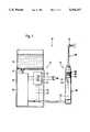
- FIG. 1is a diagrammatic view of an oral irrigating apparatus
- FIG. 2 ais a longitudinal sectional view of the casing of the hand-held unit of the oral irrigating apparatus and FIG. 2b is a corresponding side view showing the casing only in the area of the operating means;
- FIG. 3is a block diagram to explain the principle of function of the electrical devices of the oral irrigating apparatus.
- an oral irrigating apparatus 10comprising a hand-held unit 12 and a base unit 14. From a water reservoir 16 seated on top of the base unit 14, water is admitted through an inlet conduit 17 to a pump unit 20 arranged in a housing 18 of the base unit 14. Water is discharged from the pump unit 20 through a hose 19 leading to the hand-held unit 12.
- an electrical control system 22for open or closed loop control of the pump unit 20 comprising a pump and an electric motor.
- the control system 22is user-adjustable to a predetermined set point indicative of the jet pressure of the oral irrigating apparatus by means of a schematically shown actuation device 24 provided on the base unit 14.
- a supply connection 26connects the base unit 14 to an electricity supply.
- Embedded in the wall of the hose 19are two electrical or optical or other conductors 21, 23 having their one ends connected to the control system 22 in the base unit 14 while their other ends are connected to a switching unit 44 (FIG. 2) in the handle section 28 of the hand-held unit 12.
- a jet attachment 30having a nozzle 32 adapted to discharge the fluid delivered to the hand-held unit 12 through the hose 19.
- An operating means 33is slidably arranged on the handle section 28. Whilst the operating means 33 is comprised of a slide switch 34 and an integral non-locking pushbutton 35, it will be understood that it may also be embodied in other forms, as a toggle switch, rocker switch, or the like.
- the handle section 28substantially comprises a casing with a casing wall 36 receiving in its interior a casing insert 38.
- the hose 19is secured to a neck of the casing insert 38 by means of a clamping structure 37.
- a central aperture 40 of the casing insert 38terminates in the area of a ring seal 39 at the head end of the handle section 28.
- coupling means 42are provided for coupling the jet attachment 30 with the handle section 28.
- a switching unit 44is affixed to the casing insert 38 opposite two plungers 46, 47 received in openings in the casing wall 36.
- the switching unitis made by thick-film technology.
- any type of electric switchmay be used, including in particular microswitches, provided their size matches the available space.
- the plungers 46 and 47serve to actuate the contacts of two switches 62 and 64 (FIG. 3) of the switching unit 44.
- the plungers 46 and 47are guided by the side walls of the openings in the casing wall 36.
- a foil 48 connected to the casing wall 36 so as to be impervious to contaminants and humidityextends over and above the plungers 46 and 47.
- the foil 48seals the casing in the area of the plungers 46 and 47, thus preventing the entrance of contaminants or humidity in the interior of the handle section 28.
- the operating means 33is slidably mounted on the casing wall 36 above the plungers 46, 7.
- the fastening means for locating the operating means 3 in position on the casing wall 36 of the handle section 28are not illustrated in greater detail in the Figures.
- noses or tangs integrally formed on the underside of the operating means 33may be provided for locking engagement with guide grooves in the casing wall 36, or other conventional fastening methods may be selected.
- the operating means 33is configured as an approximately rectangular plate structure 49 conformed to the curvature of the casing wall 36. Formed integrally with the underside of the plate structure 49 is a resilient tongue 50 which in the On position of the operating means 33 shown acts centrally on the plunger 47 as well as on the associated switch 62 (FIG. 3). This part of the operating means 33 referred to as a slide switch 34 for actuating the switch 62 serves to turn the oral irrigating apparatus 10 on and off.
- two apertures 52are provided extending parallel to the transverse rib members 60.
- the apertures 52do not extend over the entire cross dimensions of the plate structure 49, terminating rather in an edge area 51 of the plate structure 49.
- the area between the apertures 52forms a surface in the form of a strip 53 having resilient properties.
- a button-shaped protrusion 54is provided in the center of the strip 53. The application of pressure to the non-locking pushbutton 35 actuates the plunger 46 and thus the switch 64 (FIG. 3) of the switching unit 44.
- the switch 64is actuable only if the slide switch 34 is in the On position illustrated in FIG. 2.
- the operating means 33In the Off position in which the operating means 33 is displaced in the direction of the foot end of the handle section 28 until a central axis 56 of the non-locking pushbutton 35 is in the mid-area 58 intermediate the plungers 46 and 47, an actuation of the switch 64 by the non-locking pushbutton 35 is prevented from occurring.
- the tongue 50 of the slide switch 34lies on the side adjacent to the plunger 47, causing opening of the switch 62 and turning the oral irrigating apparatus 10 off.
- the operating means 33that is, the slide switch 34 is moved to the On position, causing, as shown in FIG. 2, the tongue 50 to actuate the switch 62 (FIG. 3) through the plunger 47 and to activate the pump unit 20, as will be explained in greater detail in the following with reference to FIG. 3.
- the pump unit 20will propel liquid at a pressure suited to meet the individual user's needs to the nozzle 32 on the handle section 28 from which it is discharged as a jet.
- the usermay actuate the non-locking pushbutton 35 to increase the pressure of the cleansing jet to a predetermined, particularly maximum, value, which will be maintained as long as the non-locking pushbutton 35 is actuated.
- the userwill stop pressing down on the non-locking pushbutton 35, causing the pressure of the water jet to return automatically to the value preselected with the actuation device 24.
- the operating means 33 of the present inventionin addition to being adapted to turn the oral irrigating apparatus 10 on and off, enables an operating parameter to be varied over a shorter or longer period of time, involving in the present embodiment in particular an increase in the jet pressure of the oral irrigating apparatus 10, which is accomplished by single-hand control of the operating means 33 on the hand-held unit 12.
- this functionmay also be performed by two separate controls 34, 35 provided on the hand-held unit 12.
- the configuration of the electric circuit of the two switches 62 and 64 of the switching unit 44 actuable by the slide switch 34 and the non-locking pushbutton 35will be explained in the following with reference to the block diagram of FIG. 3.
- a particular aspect of this circuit configurationresides in the fact that the electrical connection between the hand-held unit 12 and the base unit 14 is established by just two electrical conductors 21, 23 while yet allowing a variation of at least two operating parameters involving the On/Off state parameter and the jet pressure or operating power parameter of the pump unit.
- the circuit configurationis comprised of two parts, including the switching unit 44 accommodated in the handle section 28 and comprising the switches 62 and 64, wherein a resistor 72 is connected in parallel with switch 64, and the electric circuit 67 provided in the base unit 14.
- the two unitsare interconnected electrically by means of conductors 21 and 23 and mechanically through the hose 19.
- the electric circuit 67includes a rectifier 66 adapted to be connected to an ac source of voltage by a supply connection 26.
- the output potential of rectifier 6is applied to the one contact of switch 62 through the electrical conductor 21.
- Switch 62, switch 64 and a resistor 73combine in this sequence to form a series circuit having its base point applied to a reference potential, in particular frame potential.
- resistor 72By arranging resistor 72 in parallel with switch 64, the potential of the electrical conductor 23 branching off from the switch 64 or of a reference point 69 inside the circuit 67 varies as follows: With the switch 62 open--which corresponds to the Off state of the oral irrigating apparatus 10--frame potential will reside at reference point 69, irrespective of whether switch 64 is open or closed. Closing of switch 62 with switch 64 open causes the potential across reference point 69 to assume such values as are determined by the ratio of the voltage division produced by resistors 72 and 73. If switch 64 is closed with switch 62 being equally closed, resistor 72 will be bypassed, causing the potential across reference point 69 to be increased to a maximum value determined by the output potential of rectifier 66.
- the value determined by the ratio of the voltage division of resistors 72, 73 as well as any higher value at reference point 69is sufficient to turn on a standby unit 86 which is connected to reference point 69 through a control line 88 and actuates in turn a control system 68 and the pump unit 20 connected thereto.
- the control system 68receives the set point of the pumping power through a set point signal line 70. This set point is adjusted by the ratio of the voltage division of a voltage divider 82 to which the supply voltage is applied.
- One of the resistors of the voltage divider 82is formed by a variable resistor, that is, the actuation device 24.
- the output pressure of the pump unit 20 and thus the pressure of the jet discharged from the nozzle 32may be set at specific values agreeable to the user.
- the set point signalis applied to the input of a first switch 71.
- the input of a second switch 71is connected to the center tap of a second voltage divider 84 equally receiving the supply voltage. While a variable set point is adjustable with the first voltage divider 82, the second voltage divider 84 is dimensioned such as to supply a fixed set point corresponding, for example, to an approximately maximum pumping power and thus a maximum jet pressure.
- the outputs of the two switches 71are connected together for onward transmission to the control system 68 through the set point signal line 70.
- the switches 71are, for example, part of an analog multiplexer 74 and may be electrically driven to the On/Off state by control lines 76.
- control lines 76By inserting an inverter 75 in one of the two control lines 76, the two switches 71 are driven in complementary fashion, causing only one of the two switches 71 to be closed at a time, the other switch being open.
- a discriminator or comparator function 77is provided between the electrical conductor 23 and the control lines 76.
- the internal operating point of the comparator function 77is assigned a logic level such that it switches its digital output state or the potential of the control lines 76 from 1 to 0 or vice versa if the value of the input potential across reference point 69 increases from the value predetermined by the ratio of the voltage division of resistors 72 and 73 to the value of the supply voltage.
- This potential jumpoccurs at reference point 69 precisely when the non-locking pushbutton 35 actuates switch 64 while switch 62 is closed. If only switch 62 is closed, the potential level of the control lines 76 causes the signals of a signal line 78 connected to the center tap of the voltage divider 82 to be applied to the set point signal line 70 through one of the switches 71.
- switch 64Closing of switch 64 increases the potential across reference point 69 to the level of the supply voltage, and the control lines 76 are switched over in complementary fashion by means of the comparator function 77.
- the signal line 80 connected to the center tap of the voltage divider 84is connected to the set point signal line 70. It follows from this description that, with switch 62 closed, the set point signal line 70 receives different set points in dependence upon the position of switch 64, which set points are determined by the ratio of the voltage division of voltage dividers 82 and 84.
- the set point determined by voltage divider 84corresponds particularly to a maximum value of the pumping power or jet pressure, which comes to bear if switch 64 is actuated by means of non-locking pushbutton 35 with the appliance in turned-on condition.
- the pumping power or the jet pressureis determined by the ratio of the voltage division of the variable voltage divider 82 which is variable by means of the actuation device 24 on the base unit 14. It will be understood that the voltage dividers 82, 84 may also be supplied with the motor voltage, in which event the set point becomes dependent on the rotational speed of the motor and a control of the motor speed is made possible.
- the present inventionis not limited to the specific application to oral irrigating apparatus and may find usage in any appliance for oral hygiene requiring an adjustment of two operating parameters by single-hand control.
- the electronic circuitryproves advantageous particularly if it is necessary or advisable to provide a minimum possible number of electrical conductors between a hand-held unit and a base unit of an oral irrigating apparatus.
- a minimum number of electrically conducting connectionsis necessary for reasons of operational reliability and, in the present example, the rather complex arrangement of the electrical conductors in the side wall of a water-conducting hose.
Landscapes
- Health & Medical Sciences (AREA)
- Dentistry (AREA)
- Epidemiology (AREA)
- Life Sciences & Earth Sciences (AREA)
- Animal Behavior & Ethology (AREA)
- General Health & Medical Sciences (AREA)
- Public Health (AREA)
- Veterinary Medicine (AREA)
- Brushes (AREA)
- Dental Tools And Instruments Or Auxiliary Dental Instruments (AREA)
Abstract
Description
Claims (13)
Applications Claiming Priority (2)
| Application Number | Priority Date | Filing Date | Title |
|---|---|---|---|
| DE3937875ADE3937875A1 (en) | 1989-11-14 | 1989-11-14 | ELECTRICALLY OPERATED ORAL CARE DEVICE |
| DE3937875 | 1989-11-14 |
Publications (1)
| Publication Number | Publication Date |
|---|---|
| US5344317Atrue US5344317A (en) | 1994-09-06 |
Family
ID=6393511
Family Applications (1)
| Application Number | Title | Priority Date | Filing Date |
|---|---|---|---|
| US07/855,703Expired - Fee RelatedUS5344317A (en) | 1989-11-14 | 1992-05-06 | Electrically powered appliance for oral hygiene |
Country Status (4)
| Country | Link |
|---|---|
| US (1) | US5344317A (en) |
| EP (1) | EP0500541B1 (en) |
| DE (2) | DE3937875A1 (en) |
| WO (1) | WO1991007144A1 (en) |
Cited By (109)
| Publication number | Priority date | Publication date | Assignee | Title |
|---|---|---|---|---|
| USD358884S (en) | 1993-11-25 | 1995-05-30 | U.S. Philips Corporation | Nozzle for waterjet |
| DE4436927A1 (en)* | 1994-10-15 | 1996-05-02 | Braun Ag | Oral care device |
| US5662605A (en)* | 1995-11-24 | 1997-09-02 | Hurwitz; Stanley | Ear irrigation device and method |
| US5697784A (en)* | 1994-06-22 | 1997-12-16 | U.S. Philips Corporation | Dental cleaning device with a grip member |
| USD406334S (en)* | 1997-07-22 | 1999-03-02 | Inventive Care Technologies | Portable dental irrigator for pets |
| US5993402A (en)* | 1996-11-06 | 1999-11-30 | Braun Ag | Pressure relief valve for an oral irrigator |
| US6030212A (en)* | 1996-09-27 | 2000-02-29 | Dentsply Research & Development Corp. | Stacking reservoir and scaler system |
| US6056710A (en)* | 1998-12-18 | 2000-05-02 | Teledyne Industries, Inc. | Oral irrigator housing |
| USD425615S (en)* | 1998-12-18 | 2000-05-23 | Teledyne Industries, Inc. | Oral irrigator cover |
| USD425981S (en)* | 1998-12-18 | 2000-05-30 | Teledyne Industries, Inc. | Oral irrigator medicament reservoir |
| USD426633S (en)* | 1998-12-18 | 2000-06-13 | Teledyne Industries, Inc. | Oral irrigator base |
| WO2000037017A1 (en)* | 1998-12-18 | 2000-06-29 | Teledyne Industries, Inc. Doing Business As Teledyne Water Pik | Oral irrigator handle assembly having a pressure control valve and stop valve assembly |
| US6132445A (en)* | 1999-09-23 | 2000-10-17 | Pavanelli; Gianni | Device for the cleaning and hygiene of the oral cavity, in particular of the tongue |
| USD435651S (en)* | 1999-03-10 | 2000-12-26 | Braun Gmbh | Jet tip for a oral irrigator |
| USD435905S1 (en) | 1998-12-18 | 2001-01-02 | Water Pik, Inc., a California corporation | Oral irrigator handle |
| US6203320B1 (en)* | 1998-12-22 | 2001-03-20 | Unilever Home & Personal Care Usa, Division Of Conopco, Inc. | Electric toothbrush and method combining bristle and pulsed liquid irrigation cleansing to oral cavity |
| US6217328B1 (en) | 2000-02-07 | 2001-04-17 | William L. Oliver | Oral hygiene system |
| US6450811B1 (en) | 1999-09-24 | 2002-09-17 | Dentsply Research & Development Corp. | Dental scaler system and method |
| US20030128488A1 (en)* | 2000-10-20 | 2003-07-10 | Uwe Katzer | Electric appliance capable of receiving power from a battery or an external source |
| US20040014001A1 (en)* | 2000-08-08 | 2004-01-22 | Jon Nordmo | Dental care device |
| USD486573S1 (en) | 2002-12-31 | 2004-02-10 | Water Pik, Inc. | Hand held oral irrigator |
| US20050004498A1 (en)* | 2003-07-03 | 2005-01-06 | Michael Klupt | Dental hygiene device |
| US20060078844A1 (en)* | 2004-10-07 | 2006-04-13 | Goldman Paul D | Oral care systems, oral care devices and methods of use |
| USD530010S1 (en) | 2004-03-17 | 2006-10-10 | Water Pik, Inc. | Base for an oral implement |
| US20070082317A1 (en)* | 2005-10-11 | 2007-04-12 | Ya Horng Electronic Co., Ltd. | Atomization apparatus of a washing machine for washing a human cavity tissue |
| USD565175S1 (en) | 2006-02-24 | 2008-03-25 | Water Pik, Inc. | Water jet base |
| USD574952S1 (en) | 2006-02-24 | 2008-08-12 | Water Pik, Inc. | Water jet handle |
| US20090070949A1 (en)* | 2007-05-31 | 2009-03-19 | The Gillette Company | Oral Care Compositions, Methods, Devices and Systems |
| US20090100620A1 (en)* | 2007-10-22 | 2009-04-23 | Colgate-Palmolive | Oral Care Implement With Air Flossing System |
| US7670141B2 (en) | 2006-07-07 | 2010-03-02 | Water Pik, Inc. | Oral irrigator |
| USD629884S1 (en) | 2009-12-16 | 2010-12-28 | Water Pik, Inc. | Powered irrigator for sinus cavity rinse |
| US8113832B2 (en) | 2002-12-31 | 2012-02-14 | Water Pik, Inc. | Hand held oral irrigator |
| US20120199150A1 (en)* | 2011-02-09 | 2012-08-09 | Minh Le | Apparatus And Method For Attaching And/Or Repairing Fake Nails |
| US8250763B2 (en) | 2005-04-27 | 2012-08-28 | The Gillette Company | Battery-operated razor |
| USD669978S1 (en)* | 2010-11-30 | 2012-10-30 | Koninklijke Philips Electronics N.V. | Dental cleaning instrument |
| USD670373S1 (en) | 2010-12-16 | 2012-11-06 | Water Pik, Inc. | Powered irrigator for sinus cavity rinse |
| USD671637S1 (en)* | 2010-11-30 | 2012-11-27 | Koninklijke Philips Electronics N.V. | Handle for dental cleaning instrument |
| US8408483B2 (en) | 2006-02-24 | 2013-04-02 | Water Pik, Inc. | Adjustable flow regulator for dental water jet |
| US8444416B2 (en) | 2005-04-26 | 2013-05-21 | Braun Gmbh | Valves for personal care devices |
| US8458841B2 (en) | 2007-06-20 | 2013-06-11 | Braun Gmbh | Brush head for a toothbrush |
| EP2727556A1 (en)* | 2012-11-02 | 2014-05-07 | Braun GmbH | Oral irrigator |
| USD707350S1 (en) | 2012-10-11 | 2014-06-17 | Water Pik, Inc. | Handheld water flosser |
| US8801667B2 (en) | 2009-12-16 | 2014-08-12 | Water Pik, Inc. | Pump for powered irrigator for sinus cavity rinse |
| US20140272769A1 (en)* | 2013-03-15 | 2014-09-18 | Water Pik, Inc. | Fluid activated switch for oral irrigator |
| US20140272782A1 (en)* | 2013-03-14 | 2014-09-18 | Water Pik, Inc. | Oral Irrigator with Massage Mode |
| USD714929S1 (en) | 2013-03-14 | 2014-10-07 | Water Pik, Inc. | Base for water flosser |
| USD717427S1 (en) | 2013-03-14 | 2014-11-11 | Water Pik, Inc. | Handle for water flosser |
| USD725770S1 (en) | 2013-03-14 | 2015-03-31 | Water Pik, Inc. | Reservoir for water flosser |
| USD756122S1 (en) | 2009-01-28 | 2016-05-17 | Water Pik, Inc. | Oral irrigator tip |
| USD772396S1 (en) | 2014-12-01 | 2016-11-22 | Water Pik, Inc. | Handheld oral irrigator |
| USD772397S1 (en) | 2014-12-01 | 2016-11-22 | Water Pik, Inc. | Oral irrigator with a charging device |
| US20170056142A1 (en)* | 2014-05-16 | 2017-03-02 | Koninklijke Philips N.V. | Oral cleaning device with adjustable fluid dynamics |
| USD780908S1 (en) | 2015-11-03 | 2017-03-07 | Water Pik, Inc. | Handheld oral irrigator |
| USD782657S1 (en) | 2016-03-02 | 2017-03-28 | Water Pik, Inc. | Oral irrigator handle |
| USD782656S1 (en) | 2016-01-25 | 2017-03-28 | Water Pik, Inc. | Oral irrigator |
| USD783810S1 (en) | 2016-02-22 | 2017-04-11 | Water Pik, Inc. | Handle for an oral irrigator |
| USD783809S1 (en) | 2016-01-25 | 2017-04-11 | Water Pik, Inc. | Oral irrigator handle |
| USD786422S1 (en) | 2016-01-25 | 2017-05-09 | Water Pik, Inc. | Oral irrigator |
| USD788907S1 (en) | 2013-03-14 | 2017-06-06 | Water Pik, Inc. | Water flosser base unit with reservoir lid |
| USD794773S1 (en) | 2016-07-19 | 2017-08-15 | Water Pik, Inc. | Oral irrigator |
| USD796028S1 (en) | 2016-07-19 | 2017-08-29 | Water Pik, Inc. | Oral irrigator |
| USD802120S1 (en) | 2007-02-27 | 2017-11-07 | Water Pik, Inc. | Tip for oral irrigator |
| USD802119S1 (en) | 2016-03-02 | 2017-11-07 | Water Pik, Inc. | Oral irrigator |
| USD802747S1 (en) | 2016-07-19 | 2017-11-14 | Water Pik, Inc. | Reservoir for oral irrigator |
| USD804018S1 (en) | 2016-07-19 | 2017-11-28 | Water Pik, Inc. | Base for an oral irrigator |
| USD804016S1 (en) | 2016-02-05 | 2017-11-28 | Water Pik, Inc. | Handheld oral irrigator |
| USD807822S1 (en) | 2016-07-19 | 2018-01-16 | Water Pik, Inc. | Power supply cartridge |
| USD809651S1 (en) | 2016-07-19 | 2018-02-06 | Water Pik, Inc. | Combination base and reservoir for an oral irrigator |
| USD809650S1 (en) | 2016-02-22 | 2018-02-06 | Water Pik, Inc. | Oral irrigator |
| WO2018076127A1 (en)* | 2016-10-24 | 2018-05-03 | 朱柯明 | Tooth-cleaning device and u-shaped toothbrush head structure thereof |
| US9980793B2 (en) | 2013-11-27 | 2018-05-29 | Water Pik, Inc. | Oral hygiene system |
| USD819956S1 (en) | 2016-01-25 | 2018-06-12 | Water Pik, Inc. | Kit bag |
| USD822196S1 (en) | 2016-01-14 | 2018-07-03 | Water Pik, Inc. | Oral irrigator |
| USD822826S1 (en) | 2016-12-15 | 2018-07-10 | Water Pik, Inc. | Oral irrigator base |
| USD822825S1 (en) | 2016-12-15 | 2018-07-10 | Water Pik, Inc. | Oral irrigator unit |
| US10016254B2 (en) | 2013-12-20 | 2018-07-10 | Water Pik, Inc. | Dental water jet |
| US10022207B2 (en) | 2013-11-27 | 2018-07-17 | Water Pik, Inc. | Oral irrigator with slide pause switch |
| USD825741S1 (en) | 2016-12-15 | 2018-08-14 | Water Pik, Inc. | Oral irrigator handle |
| USD829887S1 (en) | 2017-02-06 | 2018-10-02 | Water Pik, Inc. | Oral irrigator reservoir |
| USD829886S1 (en) | 2016-12-15 | 2018-10-02 | Water Pik, Inc. | Oral irrigator base |
| US10105201B2 (en) | 2012-10-11 | 2018-10-23 | Water Pik, Inc. | Interdental cleaner using water supply |
| USD832418S1 (en) | 2016-12-15 | 2018-10-30 | Water Pik, Inc. | Oral irrigator base |
| USD832419S1 (en) | 2016-12-15 | 2018-10-30 | Water Pik, Inc. | Oral irrigator unit |
| USD832420S1 (en) | 2016-12-15 | 2018-10-30 | Water Pik, Inc. | Oral irrigator base |
| USD833000S1 (en) | 2016-12-15 | 2018-11-06 | Water Pik, Inc. | Oral irrigator unit |
| USD833601S1 (en) | 2017-02-06 | 2018-11-13 | Water Pik, Inc. | Oral irrigator |
| USD833600S1 (en) | 2016-12-15 | 2018-11-13 | Water Pik, Inc. | Oral irrigator reservoir |
| USD833602S1 (en) | 2017-02-06 | 2018-11-13 | Water Pik, Inc. | Oral irrigator base |
| USD834180S1 (en) | 2016-12-15 | 2018-11-20 | Water Pik, Inc. | Oral irrigator base |
| USD839409S1 (en) | 2016-12-15 | 2019-01-29 | Water Pik, Inc. | Oral irrigator unit |
| USD840023S1 (en) | 2016-12-15 | 2019-02-05 | Water Pik, Inc. | Oral irrigator reservoir |
| USD840022S1 (en) | 2016-12-15 | 2019-02-05 | Water Pik, Inc. | Oral irrigator handle |
| US10258442B2 (en) | 2009-03-20 | 2019-04-16 | Water Pik, Inc. | Oral irrigator appliance with radiant energy delivery for bactericidal effect |
| USD867579S1 (en) | 2016-12-15 | 2019-11-19 | Water Pik, Inc. | Oral irrigator unit |
| USD868243S1 (en) | 2018-03-16 | 2019-11-26 | Water Pik, Inc. | Oral irrigator tip |
| EP3572037A1 (en)* | 2018-05-24 | 2019-11-27 | Braun GmbH | Oral irrigator |
| USD877324S1 (en) | 2018-05-17 | 2020-03-03 | Water Pik, Inc. | Oral irrigator handle |
| USD888936S1 (en) | 2019-02-22 | 2020-06-30 | Water Pik, Inc. | Cordless water flosser |
| USD889636S1 (en) | 2019-02-22 | 2020-07-07 | Water Pik, Inc. | Water flosser |
| US10779922B2 (en) | 2016-12-15 | 2020-09-22 | Water Pik, Inc. | Pause valve and swivel assemblies for oral irrigator handle |
| US10835356B2 (en) | 2016-01-25 | 2020-11-17 | Water Pik, Inc. | Swivel assembly for oral irrigator handle |
| US10993867B2 (en) | 2016-03-02 | 2021-05-04 | Water Pik, Inc. | Actuation assembly for an oral irrigator |
| US11213376B2 (en) | 2016-01-25 | 2022-01-04 | Water Pik, Inc. | Reduced form factor oral irrigator |
| CN114521980A (en)* | 2021-12-31 | 2022-05-24 | 江西瑞圣特科技有限责任公司 | Tooth flushing device with flexible pressure electric control nozzle |
| US11389279B2 (en) | 2016-12-15 | 2022-07-19 | Water Pik, Inc. | Oral irrigator with magnetic attachment |
| USD966498S1 (en) | 2020-09-15 | 2022-10-11 | Water Pik, Inc. | Oral irrigator |
| US20230074717A1 (en)* | 2021-09-07 | 2023-03-09 | Fly Cat Electrical Co., Ltd. | Waterproof oral irrigator |
| US11826214B2 (en) | 2014-12-01 | 2023-11-28 | Water Pik, Inc. | Oral irrigator |
| USD1016274S1 (en) | 2021-02-16 | 2024-02-27 | Water Pik, Inc. | Oral irrigator |
Families Citing this family (2)
| Publication number | Priority date | Publication date | Assignee | Title |
|---|---|---|---|---|
| DE4429219C2 (en)* | 1994-08-18 | 1996-07-04 | Moser Gmbh Kuno | Oral irrigator |
| EP2541214A1 (en)* | 2011-06-28 | 2013-01-02 | Braun GmbH | Personal care device and method for control thereof |
Citations (13)
| Publication number | Priority date | Publication date | Assignee | Title |
|---|---|---|---|---|
| US2984008A (en)* | 1957-11-12 | 1961-05-16 | Weisberg Alexander | Air and water control for dental drill |
| US3449831A (en)* | 1967-07-03 | 1969-06-17 | Lazaros C Vandis | Dental handpiece control |
| GB1264138A (en)* | 1969-01-10 | 1972-02-16 | ||
| DE2238363A1 (en)* | 1972-08-04 | 1974-02-14 | Baer Elektrowerke Kg | ELECTRIC CORD SWITCH |
| EP0025456A1 (en)* | 1979-03-15 | 1981-03-25 | Matsushita Electric Works, Ltd. | Dental cleaner |
| DE3101941A1 (en)* | 1981-01-22 | 1982-08-19 | Gimelli & Co. AG, 3052 Zollikofen | Handpiece for a mouth and tooth spraying device |
| US4363626A (en)* | 1980-05-15 | 1982-12-14 | Sybron Corporation | Dental syringe |
| DE3143196A1 (en)* | 1981-10-30 | 1983-05-19 | Matsushita Electric Industrial Co., Ltd., Kadoma, Osaka | Oral cavity cleaner |
| DE3420213A1 (en)* | 1984-05-30 | 1985-12-05 | Gimelli & Co. AG, Zollikofen | HAND DEVICE FOR BODY CARE |
| DE3500085A1 (en)* | 1985-01-03 | 1986-07-03 | Kaltenbach & Voigt Gmbh & Co, 7950 Biberach | DENTAL HANDPIECE |
| US4619612A (en)* | 1983-10-12 | 1986-10-28 | Siemens Aktiengesellschaft | Dental spray handpiece |
| DE3601617A1 (en)* | 1986-01-21 | 1987-07-23 | Guenter Petz | Mouth douche |
| US5197458A (en)* | 1989-06-23 | 1993-03-30 | Ricoh Elemex Corporation | Mouth cavity sanitary device |
- 1989
- 1989-11-14DEDE3937875Apatent/DE3937875A1/ennot_activeCeased
- 1990
- 1990-09-05DEDE9090913198Tpatent/DE59002121D1/ennot_activeExpired - Fee Related
- 1990-09-05WOPCT/DE1990/000674patent/WO1991007144A1/enactiveIP Right Grant
- 1990-09-05EPEP90913198Apatent/EP0500541B1/ennot_activeExpired - Lifetime
- 1992
- 1992-05-06USUS07/855,703patent/US5344317A/ennot_activeExpired - Fee Related
Patent Citations (14)
| Publication number | Priority date | Publication date | Assignee | Title |
|---|---|---|---|---|
| US2984008A (en)* | 1957-11-12 | 1961-05-16 | Weisberg Alexander | Air and water control for dental drill |
| US3449831A (en)* | 1967-07-03 | 1969-06-17 | Lazaros C Vandis | Dental handpiece control |
| GB1264138A (en)* | 1969-01-10 | 1972-02-16 | ||
| DE2238363A1 (en)* | 1972-08-04 | 1974-02-14 | Baer Elektrowerke Kg | ELECTRIC CORD SWITCH |
| EP0025456A1 (en)* | 1979-03-15 | 1981-03-25 | Matsushita Electric Works, Ltd. | Dental cleaner |
| DE3036781C1 (en)* | 1979-03-15 | 1986-09-11 | Matsushita Electric Works, Ltd., Kadoma, Osaka | Mouth cleaning device |
| US4363626A (en)* | 1980-05-15 | 1982-12-14 | Sybron Corporation | Dental syringe |
| DE3101941A1 (en)* | 1981-01-22 | 1982-08-19 | Gimelli & Co. AG, 3052 Zollikofen | Handpiece for a mouth and tooth spraying device |
| DE3143196A1 (en)* | 1981-10-30 | 1983-05-19 | Matsushita Electric Industrial Co., Ltd., Kadoma, Osaka | Oral cavity cleaner |
| US4619612A (en)* | 1983-10-12 | 1986-10-28 | Siemens Aktiengesellschaft | Dental spray handpiece |
| DE3420213A1 (en)* | 1984-05-30 | 1985-12-05 | Gimelli & Co. AG, Zollikofen | HAND DEVICE FOR BODY CARE |
| DE3500085A1 (en)* | 1985-01-03 | 1986-07-03 | Kaltenbach & Voigt Gmbh & Co, 7950 Biberach | DENTAL HANDPIECE |
| DE3601617A1 (en)* | 1986-01-21 | 1987-07-23 | Guenter Petz | Mouth douche |
| US5197458A (en)* | 1989-06-23 | 1993-03-30 | Ricoh Elemex Corporation | Mouth cavity sanitary device |
Cited By (184)
| Publication number | Priority date | Publication date | Assignee | Title |
|---|---|---|---|---|
| USD358884S (en) | 1993-11-25 | 1995-05-30 | U.S. Philips Corporation | Nozzle for waterjet |
| USD358883S (en) | 1993-11-25 | 1995-05-30 | U.S. Philips Corporation | Waterjet-handgrip |
| US5697784A (en)* | 1994-06-22 | 1997-12-16 | U.S. Philips Corporation | Dental cleaning device with a grip member |
| DE4436927A1 (en)* | 1994-10-15 | 1996-05-02 | Braun Ag | Oral care device |
| DE4436927C2 (en)* | 1994-10-15 | 2002-08-01 | Braun Gmbh | Oral care device |
| US5662605A (en)* | 1995-11-24 | 1997-09-02 | Hurwitz; Stanley | Ear irrigation device and method |
| US6030212A (en)* | 1996-09-27 | 2000-02-29 | Dentsply Research & Development Corp. | Stacking reservoir and scaler system |
| US6293793B1 (en) | 1996-09-27 | 2001-09-25 | Dentsply Research & Development Corp. | Stackable reservoir and scaler system |
| US5993402A (en)* | 1996-11-06 | 1999-11-30 | Braun Ag | Pressure relief valve for an oral irrigator |
| USD406334S (en)* | 1997-07-22 | 1999-03-02 | Inventive Care Technologies | Portable dental irrigator for pets |
| US6056710A (en)* | 1998-12-18 | 2000-05-02 | Teledyne Industries, Inc. | Oral irrigator housing |
| USD426633S (en)* | 1998-12-18 | 2000-06-13 | Teledyne Industries, Inc. | Oral irrigator base |
| WO2000037017A1 (en)* | 1998-12-18 | 2000-06-29 | Teledyne Industries, Inc. Doing Business As Teledyne Water Pik | Oral irrigator handle assembly having a pressure control valve and stop valve assembly |
| USD425981S (en)* | 1998-12-18 | 2000-05-30 | Teledyne Industries, Inc. | Oral irrigator medicament reservoir |
| US6699208B2 (en) | 1998-12-18 | 2004-03-02 | Water Pik, Inc. | Oral irrigator housing |
| USD435905S1 (en) | 1998-12-18 | 2001-01-02 | Water Pik, Inc., a California corporation | Oral irrigator handle |
| US6475173B1 (en) | 1998-12-18 | 2002-11-05 | Water Pik, Inc. | Oral irrigator housing |
| USD425615S (en)* | 1998-12-18 | 2000-05-23 | Teledyne Industries, Inc. | Oral irrigator cover |
| US6247929B1 (en) | 1998-12-18 | 2001-06-19 | Teledyne Industries, Inc. | Oral irrigator handle assembly having a pressure control valve and stop valve assembly |
| US6203320B1 (en)* | 1998-12-22 | 2001-03-20 | Unilever Home & Personal Care Usa, Division Of Conopco, Inc. | Electric toothbrush and method combining bristle and pulsed liquid irrigation cleansing to oral cavity |
| USD435651S (en)* | 1999-03-10 | 2000-12-26 | Braun Gmbh | Jet tip for a oral irrigator |
| US6132445A (en)* | 1999-09-23 | 2000-10-17 | Pavanelli; Gianni | Device for the cleaning and hygiene of the oral cavity, in particular of the tongue |
| US6450811B1 (en) | 1999-09-24 | 2002-09-17 | Dentsply Research & Development Corp. | Dental scaler system and method |
| US6217328B1 (en) | 2000-02-07 | 2001-04-17 | William L. Oliver | Oral hygiene system |
| US20040014001A1 (en)* | 2000-08-08 | 2004-01-22 | Jon Nordmo | Dental care device |
| US6964569B2 (en)* | 2000-08-08 | 2005-11-15 | Jon Nordmo | Dental care device |
| US20030128488A1 (en)* | 2000-10-20 | 2003-07-10 | Uwe Katzer | Electric appliance capable of receiving power from a battery or an external source |
| US8113832B2 (en) | 2002-12-31 | 2012-02-14 | Water Pik, Inc. | Hand held oral irrigator |
| USD486573S1 (en) | 2002-12-31 | 2004-02-10 | Water Pik, Inc. | Hand held oral irrigator |
| US20140193774A1 (en)* | 2002-12-31 | 2014-07-10 | Water Pik, Inc. | Irrigating device with variable pressure pulse |
| US9980794B2 (en)* | 2002-12-31 | 2018-05-29 | Water Pik, Inc. | Irrigating device with variable pressure pulse |
| US10617500B2 (en) | 2002-12-31 | 2020-04-14 | Water Pik, Inc. | Oral irrigator |
| US20050004498A1 (en)* | 2003-07-03 | 2005-01-06 | Michael Klupt | Dental hygiene device |
| US7080980B2 (en)* | 2003-07-03 | 2006-07-25 | Michael Klupt | Dental hygiene device |
| USD530010S1 (en) | 2004-03-17 | 2006-10-10 | Water Pik, Inc. | Base for an oral implement |
| US20060078844A1 (en)* | 2004-10-07 | 2006-04-13 | Goldman Paul D | Oral care systems, oral care devices and methods of use |
| US8444416B2 (en) | 2005-04-26 | 2013-05-21 | Braun Gmbh | Valves for personal care devices |
| US8302316B2 (en) | 2005-04-27 | 2012-11-06 | The Gillette Company | Battery-operated razor |
| US8250763B2 (en) | 2005-04-27 | 2012-08-28 | The Gillette Company | Battery-operated razor |
| US20070082317A1 (en)* | 2005-10-11 | 2007-04-12 | Ya Horng Electronic Co., Ltd. | Atomization apparatus of a washing machine for washing a human cavity tissue |
| US10010389B2 (en) | 2006-02-24 | 2018-07-03 | Water Pik, Inc. | Dental water jet device |
| US11197745B2 (en) | 2006-02-24 | 2021-12-14 | Water Pik, Inc. | Removable fluid connection fitting for oral irrigator |
| US8808209B2 (en) | 2006-02-24 | 2014-08-19 | Water Pik, Inc. | Dental water jet irrigator handle |
| USD565175S1 (en) | 2006-02-24 | 2008-03-25 | Water Pik, Inc. | Water jet base |
| US8641649B2 (en) | 2006-02-24 | 2014-02-04 | Water Pik, Inc. | Pump for dental water jet |
| US20220361993A1 (en)* | 2006-02-24 | 2022-11-17 | Water Pik, Inc. | Dental water jet with storage container reservoir cover |
| US11432916B2 (en) | 2006-02-24 | 2022-09-06 | Water Pik, Inc. | Oral irrigator with handle support |
| US8408483B2 (en) | 2006-02-24 | 2013-04-02 | Water Pik, Inc. | Adjustable flow regulator for dental water jet |
| US11872097B2 (en)* | 2006-02-24 | 2024-01-16 | Water Pik, Inc. | Dental water jet with storage container reservoir cover |
| USD574952S1 (en) | 2006-02-24 | 2008-08-12 | Water Pik, Inc. | Water jet handle |
| US8888727B2 (en) | 2006-02-24 | 2014-11-18 | Water Pik, Inc. | Vibration damping for dental water jet |
| US9050157B2 (en) | 2006-02-24 | 2015-06-09 | Water Pik, Inc. | Dental water jet with storage container reservoir cover |
| US8403665B2 (en) | 2006-07-07 | 2013-03-26 | Water Pik, Inc. | Oral irrigator |
| USD747464S1 (en) | 2006-07-07 | 2016-01-12 | Water Pik, Inc. | Handheld oral irrigator |
| US9775692B2 (en) | 2006-07-07 | 2017-10-03 | Water Pik, Inc. | Oral irrigator with variable pressure |
| US7670141B2 (en) | 2006-07-07 | 2010-03-02 | Water Pik, Inc. | Oral irrigator |
| USD802120S1 (en) | 2007-02-27 | 2017-11-07 | Water Pik, Inc. | Tip for oral irrigator |
| USD867580S1 (en) | 2007-02-27 | 2019-11-19 | Water Pik, Inc. | Oral irrigator tip with bristles |
| US20090070949A1 (en)* | 2007-05-31 | 2009-03-19 | The Gillette Company | Oral Care Compositions, Methods, Devices and Systems |
| US8458841B2 (en) | 2007-06-20 | 2013-06-11 | Braun Gmbh | Brush head for a toothbrush |
| US20090100620A1 (en)* | 2007-10-22 | 2009-04-23 | Colgate-Palmolive | Oral Care Implement With Air Flossing System |
| US8539630B2 (en) | 2007-10-22 | 2013-09-24 | Colgate-Palmolive Company | Oral care implement with air flossing system |
| US8813291B2 (en) | 2007-10-22 | 2014-08-26 | Colgate-Palmolive Company | Oral care implement with air flossing system |
| USD756122S1 (en) | 2009-01-28 | 2016-05-17 | Water Pik, Inc. | Oral irrigator tip |
| US11173020B2 (en) | 2009-03-20 | 2021-11-16 | Water Pik, Inc. | Oral irrigator appliance with radiant energy delivery for bactericidal effect |
| US10258442B2 (en) | 2009-03-20 | 2019-04-16 | Water Pik, Inc. | Oral irrigator appliance with radiant energy delivery for bactericidal effect |
| USD629884S1 (en) | 2009-12-16 | 2010-12-28 | Water Pik, Inc. | Powered irrigator for sinus cavity rinse |
| US8801667B2 (en) | 2009-12-16 | 2014-08-12 | Water Pik, Inc. | Pump for powered irrigator for sinus cavity rinse |
| US9061096B2 (en) | 2009-12-16 | 2015-06-23 | Water Pik, Inc. | Powered irrigator for sinus cavity rinse |
| US8808245B2 (en) | 2009-12-16 | 2014-08-19 | Water Pik, Inc. | Powered irrigator for sinus cavity rinse with detachable reservoir |
| USD671637S1 (en)* | 2010-11-30 | 2012-11-27 | Koninklijke Philips Electronics N.V. | Handle for dental cleaning instrument |
| USD669978S1 (en)* | 2010-11-30 | 2012-10-30 | Koninklijke Philips Electronics N.V. | Dental cleaning instrument |
| USD670373S1 (en) | 2010-12-16 | 2012-11-06 | Water Pik, Inc. | Powered irrigator for sinus cavity rinse |
| USD694398S1 (en) | 2010-12-16 | 2013-11-26 | Water Pik, Inc. | Powered irrigator for sinus cavity rinse |
| US20120199150A1 (en)* | 2011-02-09 | 2012-08-09 | Minh Le | Apparatus And Method For Attaching And/Or Repairing Fake Nails |
| US10105201B2 (en) | 2012-10-11 | 2018-10-23 | Water Pik, Inc. | Interdental cleaner using water supply |
| USD707350S1 (en) | 2012-10-11 | 2014-06-17 | Water Pik, Inc. | Handheld water flosser |
| EP2727556A1 (en)* | 2012-11-02 | 2014-05-07 | Braun GmbH | Oral irrigator |
| WO2014068431A1 (en)* | 2012-11-02 | 2014-05-08 | Braun Gmbh | Oral irrigator |
| USD714930S1 (en) | 2013-03-14 | 2014-10-07 | Water Pik, Inc. | Reservoir for water flosser |
| USD717427S1 (en) | 2013-03-14 | 2014-11-11 | Water Pik, Inc. | Handle for water flosser |
| US20140272782A1 (en)* | 2013-03-14 | 2014-09-18 | Water Pik, Inc. | Oral Irrigator with Massage Mode |
| USD714929S1 (en) | 2013-03-14 | 2014-10-07 | Water Pik, Inc. | Base for water flosser |
| USD725770S1 (en) | 2013-03-14 | 2015-03-31 | Water Pik, Inc. | Reservoir for water flosser |
| USD718855S1 (en) | 2013-03-14 | 2014-12-02 | Water Pik, Inc. | Base for water flosser |
| USD754330S1 (en) | 2013-03-14 | 2016-04-19 | Water Pik, Inc. | Handle for a water flosser |
| US9642677B2 (en)* | 2013-03-14 | 2017-05-09 | Water Pik, Inc. | Oral irrigator with massage mode |
| US10945912B2 (en)* | 2013-03-14 | 2021-03-16 | Water Pik, Inc. | Oral irrigator with variable output fluid characteristics |
| USD740936S1 (en) | 2013-03-14 | 2015-10-13 | Water Pik, Inc. | Water flosser base unit |
| US20170239132A1 (en)* | 2013-03-14 | 2017-08-24 | Water Pik, Inc. | Oral irrigator with variable output fluid characteristics |
| USD731640S1 (en) | 2013-03-14 | 2015-06-09 | Water Pik, Inc. | Reservoir for a water flosser |
| USD798440S1 (en) | 2013-03-14 | 2017-09-26 | Water Pik, Inc. | Water flosser base unit |
| USD788907S1 (en) | 2013-03-14 | 2017-06-06 | Water Pik, Inc. | Water flosser base unit with reservoir lid |
| US9597161B2 (en) | 2013-03-14 | 2017-03-21 | Water Pik, Inc. | Oral irrigator with integrated lid and base |
| US20140272769A1 (en)* | 2013-03-15 | 2014-09-18 | Water Pik, Inc. | Fluid activated switch for oral irrigator |
| US11039906B2 (en) | 2013-11-27 | 2021-06-22 | Water Pik, Inc. | Tip ejection assembly for an oral irrigator |
| US10022207B2 (en) | 2013-11-27 | 2018-07-17 | Water Pik, Inc. | Oral irrigator with slide pause switch |
| US9980793B2 (en) | 2013-11-27 | 2018-05-29 | Water Pik, Inc. | Oral hygiene system |
| US10016254B2 (en) | 2013-12-20 | 2018-07-10 | Water Pik, Inc. | Dental water jet |
| US20170056142A1 (en)* | 2014-05-16 | 2017-03-02 | Koninklijke Philips N.V. | Oral cleaning device with adjustable fluid dynamics |
| US10130452B2 (en)* | 2014-05-16 | 2018-11-20 | Koninklijke Philips N.V. | Oral cleaning device with adjustable fluid dynamics |
| USD819196S1 (en) | 2014-12-01 | 2018-05-29 | Water Pik, Inc. | Handheld oral irrigator |
| US11826214B2 (en) | 2014-12-01 | 2023-11-28 | Water Pik, Inc. | Oral irrigator |
| USD772397S1 (en) | 2014-12-01 | 2016-11-22 | Water Pik, Inc. | Oral irrigator with a charging device |
| US12383387B2 (en) | 2014-12-01 | 2025-08-12 | Water Pik, Inc. | Oral irrigator |
| USD772396S1 (en) | 2014-12-01 | 2016-11-22 | Water Pik, Inc. | Handheld oral irrigator |
| USD780908S1 (en) | 2015-11-03 | 2017-03-07 | Water Pik, Inc. | Handheld oral irrigator |
| USD907763S1 (en) | 2016-01-14 | 2021-01-12 | Water Pik, Inc. | Oral irrigator |
| USD873025S1 (en) | 2016-01-14 | 2020-01-21 | Water Pik, Inc. | Toothbrush handle |
| USD880688S1 (en) | 2016-01-14 | 2020-04-07 | Water Pik, Inc. | Oral irrigator handle |
| USD822196S1 (en) | 2016-01-14 | 2018-07-03 | Water Pik, Inc. | Oral irrigator |
| US10835356B2 (en) | 2016-01-25 | 2020-11-17 | Water Pik, Inc. | Swivel assembly for oral irrigator handle |
| USD819956S1 (en) | 2016-01-25 | 2018-06-12 | Water Pik, Inc. | Kit bag |
| US11213376B2 (en) | 2016-01-25 | 2022-01-04 | Water Pik, Inc. | Reduced form factor oral irrigator |
| US12207983B2 (en) | 2016-01-25 | 2025-01-28 | Water Pik, Inc. | Oral irrigator handle with hose connector fittings |
| US12186147B2 (en) | 2016-01-25 | 2025-01-07 | Water Pik, Inc. | Reduced form factor oral irrigator |
| USD782656S1 (en) | 2016-01-25 | 2017-03-28 | Water Pik, Inc. | Oral irrigator |
| USD786422S1 (en) | 2016-01-25 | 2017-05-09 | Water Pik, Inc. | Oral irrigator |
| US11642203B2 (en) | 2016-01-25 | 2023-05-09 | Water Pik, Inc. | Oral irrigator handle with hose connector fittings |
| USD783809S1 (en) | 2016-01-25 | 2017-04-11 | Water Pik, Inc. | Oral irrigator handle |
| USD804016S1 (en) | 2016-02-05 | 2017-11-28 | Water Pik, Inc. | Handheld oral irrigator |
| USD815274S1 (en) | 2016-02-05 | 2018-04-10 | Water Pik, Inc. | Handheld oral irrigator |
| USD839410S1 (en) | 2016-02-22 | 2019-01-29 | Water Pik, Inc. | Oral irrigator |
| USD783810S1 (en) | 2016-02-22 | 2017-04-11 | Water Pik, Inc. | Handle for an oral irrigator |
| USD873409S1 (en) | 2016-02-22 | 2020-01-21 | Water Pik, Inc. | Oral irrigator |
| USD809650S1 (en) | 2016-02-22 | 2018-02-06 | Water Pik, Inc. | Oral irrigator |
| US10993867B2 (en) | 2016-03-02 | 2021-05-04 | Water Pik, Inc. | Actuation assembly for an oral irrigator |
| USD802119S1 (en) | 2016-03-02 | 2017-11-07 | Water Pik, Inc. | Oral irrigator |
| US11607359B2 (en) | 2016-03-02 | 2023-03-21 | Water Pik, Inc. | Actuation assembly for an oral irrigator |
| USD782657S1 (en) | 2016-03-02 | 2017-03-28 | Water Pik, Inc. | Oral irrigator handle |
| USD802747S1 (en) | 2016-07-19 | 2017-11-14 | Water Pik, Inc. | Reservoir for oral irrigator |
| USD796028S1 (en) | 2016-07-19 | 2017-08-29 | Water Pik, Inc. | Oral irrigator |
| USD804018S1 (en) | 2016-07-19 | 2017-11-28 | Water Pik, Inc. | Base for an oral irrigator |
| USD794773S1 (en) | 2016-07-19 | 2017-08-15 | Water Pik, Inc. | Oral irrigator |
| USD807822S1 (en) | 2016-07-19 | 2018-01-16 | Water Pik, Inc. | Power supply cartridge |
| USD809651S1 (en) | 2016-07-19 | 2018-02-06 | Water Pik, Inc. | Combination base and reservoir for an oral irrigator |
| WO2018076127A1 (en)* | 2016-10-24 | 2018-05-03 | 朱柯明 | Tooth-cleaning device and u-shaped toothbrush head structure thereof |
| US10779922B2 (en) | 2016-12-15 | 2020-09-22 | Water Pik, Inc. | Pause valve and swivel assemblies for oral irrigator handle |
| USD832420S1 (en) | 2016-12-15 | 2018-10-30 | Water Pik, Inc. | Oral irrigator base |
| USD870268S1 (en) | 2016-12-15 | 2019-12-17 | Water Pik, Inc. | Oral irrigator handle |
| USD825741S1 (en) | 2016-12-15 | 2018-08-14 | Water Pik, Inc. | Oral irrigator handle |
| USD834180S1 (en) | 2016-12-15 | 2018-11-20 | Water Pik, Inc. | Oral irrigator base |
| USD829886S1 (en) | 2016-12-15 | 2018-10-02 | Water Pik, Inc. | Oral irrigator base |
| USD822826S1 (en) | 2016-12-15 | 2018-07-10 | Water Pik, Inc. | Oral irrigator base |
| USD832418S1 (en) | 2016-12-15 | 2018-10-30 | Water Pik, Inc. | Oral irrigator base |
| USD832419S1 (en) | 2016-12-15 | 2018-10-30 | Water Pik, Inc. | Oral irrigator unit |
| USD893017S1 (en) | 2016-12-15 | 2020-08-11 | Water Pik, Inc. | Oral irrigator unit |
| USD822825S1 (en) | 2016-12-15 | 2018-07-10 | Water Pik, Inc. | Oral irrigator unit |
| USD833600S1 (en) | 2016-12-15 | 2018-11-13 | Water Pik, Inc. | Oral irrigator reservoir |
| USD872855S1 (en) | 2016-12-15 | 2020-01-14 | Water Pik, Inc. | Oral irrigator unit |
| USD833000S1 (en) | 2016-12-15 | 2018-11-06 | Water Pik, Inc. | Oral irrigator unit |
| USD867579S1 (en) | 2016-12-15 | 2019-11-19 | Water Pik, Inc. | Oral irrigator unit |
| USD839409S1 (en) | 2016-12-15 | 2019-01-29 | Water Pik, Inc. | Oral irrigator unit |
| USD840022S1 (en) | 2016-12-15 | 2019-02-05 | Water Pik, Inc. | Oral irrigator handle |
| US11389279B2 (en) | 2016-12-15 | 2022-07-19 | Water Pik, Inc. | Oral irrigator with magnetic attachment |
| USD840023S1 (en) | 2016-12-15 | 2019-02-05 | Water Pik, Inc. | Oral irrigator reservoir |
| USD833601S1 (en) | 2017-02-06 | 2018-11-13 | Water Pik, Inc. | Oral irrigator |
| USD833602S1 (en) | 2017-02-06 | 2018-11-13 | Water Pik, Inc. | Oral irrigator base |
| USD829887S1 (en) | 2017-02-06 | 2018-10-02 | Water Pik, Inc. | Oral irrigator reservoir |
| USD868243S1 (en) | 2018-03-16 | 2019-11-26 | Water Pik, Inc. | Oral irrigator tip |
| USD890917S1 (en) | 2018-03-16 | 2020-07-21 | Water Pik, Inc. | Oral irrigator tip |
| USD877324S1 (en) | 2018-05-17 | 2020-03-03 | Water Pik, Inc. | Oral irrigator handle |
| USD950710S1 (en) | 2018-05-17 | 2022-05-03 | Water Pik, Inc. | Oral irrigator handle |
| USD975843S1 (en) | 2018-05-17 | 2023-01-17 | Water Pik, Inc. | Oral irrigator handle |
| CN112188873A (en)* | 2018-05-24 | 2021-01-05 | 博朗有限公司 | Oral cavity flusher |
| WO2019224652A1 (en)* | 2018-05-24 | 2019-11-28 | Braun Gmbh | Oral irrigator |
| EP3572037A1 (en)* | 2018-05-24 | 2019-11-27 | Braun GmbH | Oral irrigator |
| US11744687B2 (en) | 2018-05-24 | 2023-09-05 | Braun Gmbh | Oral irrigator |
| JP7150061B2 (en) | 2018-05-24 | 2022-10-07 | ブラウン ゲーエムベーハー | oral irrigator |
| JP2021523797A (en)* | 2018-05-24 | 2021-09-09 | ブラウン ゲーエムベーハー | Oral irrigator |
| USD980414S1 (en) | 2019-02-22 | 2023-03-07 | Water Pik, Inc. | Reservoir for water flosser |
| USD913486S1 (en) | 2019-02-22 | 2021-03-16 | Water Pik, Inc. | Cordless water flosser |
| USD945601S1 (en) | 2019-02-22 | 2022-03-08 | Water Pik, Inc. | Cordless water flosser |
| USD956957S1 (en) | 2019-02-22 | 2022-07-05 | Water Pik, Inc. | Reservoir for water flosser |
| USD902385S1 (en) | 2019-02-22 | 2020-11-17 | Water Pik, Inc. | Cordless water flosser |
| USD912241S1 (en) | 2019-02-22 | 2021-03-02 | Water Pik, Inc. | Water flosser |
| USD992728S1 (en) | 2019-02-22 | 2023-07-18 | Water Pik, Inc. | Base for water flosser |
| USD969994S1 (en) | 2019-02-22 | 2022-11-15 | Water Pik, Inc. | Cordless water flosser |
| USD889636S1 (en) | 2019-02-22 | 2020-07-07 | Water Pik, Inc. | Water flosser |
| USD888936S1 (en) | 2019-02-22 | 2020-06-30 | Water Pik, Inc. | Cordless water flosser |
| USD966498S1 (en) | 2020-09-15 | 2022-10-11 | Water Pik, Inc. | Oral irrigator |
| USD1016274S1 (en) | 2021-02-16 | 2024-02-27 | Water Pik, Inc. | Oral irrigator |
| US20230074717A1 (en)* | 2021-09-07 | 2023-03-09 | Fly Cat Electrical Co., Ltd. | Waterproof oral irrigator |
| CN114521980A (en)* | 2021-12-31 | 2022-05-24 | 江西瑞圣特科技有限责任公司 | Tooth flushing device with flexible pressure electric control nozzle |
Also Published As
| Publication number | Publication date |
|---|---|
| EP0500541A1 (en) | 1992-09-02 |
| DE59002121D1 (en) | 1993-09-02 |
| EP0500541B1 (en) | 1993-07-28 |
| DE3937875A1 (en) | 1991-05-16 |
| WO1991007144A1 (en) | 1991-05-30 |
Similar Documents
| Publication | Publication Date | Title |
|---|---|---|
| US5344317A (en) | Electrically powered appliance for oral hygiene | |
| EP3572037B1 (en) | Oral irrigator | |
| EP1973490B1 (en) | Wireless system with footswitch for operating a dental or medical treatment apparatus | |
| US20120064483A1 (en) | Hard-wired and wireless system with footswitch for operating a dental or medical treatment apparatus | |
| US6179807B1 (en) | Surgical/medical irrigator with removable tip and integrated suction conduit | |
| CA2184331C (en) | Dental apparatus inducing multiple-use electrically-oscillated handpiece | |
| US4094311A (en) | Dental syringe | |
| US4442831A (en) | On/off handle for oral hygiene apparatus | |
| US4229634A (en) | Insulated switch arrangement for electric motor | |
| US4108167A (en) | Dental syringe | |
| US20030204155A1 (en) | Oral cleansing device | |
| CA1119437A (en) | Appliance for the care and cleaning of teeth and gums | |
| US20030233727A1 (en) | Hand held steam vacuum with single switch operation | |
| EP0902663A1 (en) | Electric toothbrush | |
| CN113142787A (en) | Multifunctional tooth cleaning equipment and working method thereof | |
| CN112545694A (en) | Tooth cleaning device | |
| GB2224172A (en) | Suction cleaner with alarm and fault control | |
| JP2501478Y2 (en) | Water discharge device with sensor | |
| JP6536982B2 (en) | Oral cleaning device | |
| JP3608558B2 (en) | Sanitary washing device | |
| JPH0833657A (en) | Pressure regulator of dental washer | |
| CN213468303U (en) | Multifunctional water outlet device | |
| CN118453166A (en) | Control method of tooth flushing device and tooth flushing device | |
| JPS59102030A (en) | Sanitary cleaning apparatus | |
| KR860001758Y1 (en) | Automatic brush |
Legal Events
| Date | Code | Title | Description |
|---|---|---|---|
| AS | Assignment | Owner name:BRAUN AKTIENGESELLSCHAFT, A CORP. OF THE FED REP O Free format text:ASSIGNMENT OF ASSIGNORS INTEREST.;ASSIGNORS:PACHER, LOTHAR;GASSNER, GUSTAV;VOIGT, GOTTFRIED;AND OTHERS;REEL/FRAME:006370/0887 Effective date:19920221 | |
| FEPP | Fee payment procedure | Free format text:PAYOR NUMBER ASSIGNED (ORIGINAL EVENT CODE: ASPN); ENTITY STATUS OF PATENT OWNER: LARGE ENTITY | |
| FPAY | Fee payment | Year of fee payment:4 | |
| AS | Assignment | Owner name:BRAUN GMBH, GERMANY Free format text:CHANGE OF NAME;ASSIGNOR:BRAUN AKTIENGESELLSCHAFT;REEL/FRAME:011035/0269 Effective date:19991213 | |
| FEPP | Fee payment procedure | Free format text:PAYER NUMBER DE-ASSIGNED (ORIGINAL EVENT CODE: RMPN); ENTITY STATUS OF PATENT OWNER: LARGE ENTITY Free format text:PAYOR NUMBER ASSIGNED (ORIGINAL EVENT CODE: ASPN); ENTITY STATUS OF PATENT OWNER: LARGE ENTITY | |
| FPAY | Fee payment | Year of fee payment:8 | |
| REMI | Maintenance fee reminder mailed | ||
| LAPS | Lapse for failure to pay maintenance fees | ||
| STCH | Information on status: patent discontinuation | Free format text:PATENT EXPIRED DUE TO NONPAYMENT OF MAINTENANCE FEES UNDER 37 CFR 1.362 | |
| FP | Lapsed due to failure to pay maintenance fee | Effective date:20060906 |