US5344068A - Dynamically controlled environmental control system - Google Patents
Dynamically controlled environmental control systemDownload PDFInfo
- Publication number
- US5344068A US5344068AUS08/048,494US4849493AUS5344068AUS 5344068 AUS5344068 AUS 5344068AUS 4849493 AUS4849493 AUS 4849493AUS 5344068 AUS5344068 AUS 5344068A
- Authority
- US
- United States
- Prior art keywords
- zone
- lighting
- period
- time
- time out
- Prior art date
- Legal status (The legal status is an assumption and is not a legal conclusion. Google has not performed a legal analysis and makes no representation as to the accuracy of the status listed.)
- Expired - Lifetime
Links
Images


Classifications
- F—MECHANICAL ENGINEERING; LIGHTING; HEATING; WEAPONS; BLASTING
- F24—HEATING; RANGES; VENTILATING
- F24F—AIR-CONDITIONING; AIR-HUMIDIFICATION; VENTILATION; USE OF AIR CURRENTS FOR SCREENING
- F24F11/00—Control or safety arrangements
- F—MECHANICAL ENGINEERING; LIGHTING; HEATING; WEAPONS; BLASTING
- F24—HEATING; RANGES; VENTILATING
- F24F—AIR-CONDITIONING; AIR-HUMIDIFICATION; VENTILATION; USE OF AIR CURRENTS FOR SCREENING
- F24F11/00—Control or safety arrangements
- F24F11/30—Control or safety arrangements for purposes related to the operation of the system, e.g. for safety or monitoring
- F24F11/46—Improving electric energy efficiency or saving
- F—MECHANICAL ENGINEERING; LIGHTING; HEATING; WEAPONS; BLASTING
- F24—HEATING; RANGES; VENTILATING
- F24F—AIR-CONDITIONING; AIR-HUMIDIFICATION; VENTILATION; USE OF AIR CURRENTS FOR SCREENING
- F24F11/00—Control or safety arrangements
- F24F11/50—Control or safety arrangements characterised by user interfaces or communication
- F24F11/54—Control or safety arrangements characterised by user interfaces or communication using one central controller connected to several sub-controllers
- F—MECHANICAL ENGINEERING; LIGHTING; HEATING; WEAPONS; BLASTING
- F24—HEATING; RANGES; VENTILATING
- F24F—AIR-CONDITIONING; AIR-HUMIDIFICATION; VENTILATION; USE OF AIR CURRENTS FOR SCREENING
- F24F11/00—Control or safety arrangements
- F24F11/50—Control or safety arrangements characterised by user interfaces or communication
- F24F11/56—Remote control
- F—MECHANICAL ENGINEERING; LIGHTING; HEATING; WEAPONS; BLASTING
- F24—HEATING; RANGES; VENTILATING
- F24F—AIR-CONDITIONING; AIR-HUMIDIFICATION; VENTILATION; USE OF AIR CURRENTS FOR SCREENING
- F24F11/00—Control or safety arrangements
- F24F11/50—Control or safety arrangements characterised by user interfaces or communication
- F24F11/61—Control or safety arrangements characterised by user interfaces or communication using timers
- F—MECHANICAL ENGINEERING; LIGHTING; HEATING; WEAPONS; BLASTING
- F24—HEATING; RANGES; VENTILATING
- F24F—AIR-CONDITIONING; AIR-HUMIDIFICATION; VENTILATION; USE OF AIR CURRENTS FOR SCREENING
- F24F11/00—Control or safety arrangements
- F24F11/62—Control or safety arrangements characterised by the type of control or by internal processing, e.g. using fuzzy logic, adaptive control or estimation of values
- F24F11/63—Electronic processing
- F—MECHANICAL ENGINEERING; LIGHTING; HEATING; WEAPONS; BLASTING
- F24—HEATING; RANGES; VENTILATING
- F24F—AIR-CONDITIONING; AIR-HUMIDIFICATION; VENTILATION; USE OF AIR CURRENTS FOR SCREENING
- F24F11/00—Control or safety arrangements
- F24F11/70—Control systems characterised by their outputs; Constructional details thereof
- F24F11/80—Control systems characterised by their outputs; Constructional details thereof for controlling the temperature of the supplied air
- F24F11/81—Control systems characterised by their outputs; Constructional details thereof for controlling the temperature of the supplied air by controlling the air supply to heat-exchangers or bypass channels
- F—MECHANICAL ENGINEERING; LIGHTING; HEATING; WEAPONS; BLASTING
- F24—HEATING; RANGES; VENTILATING
- F24F—AIR-CONDITIONING; AIR-HUMIDIFICATION; VENTILATION; USE OF AIR CURRENTS FOR SCREENING
- F24F11/00—Control or safety arrangements
- F24F11/30—Control or safety arrangements for purposes related to the operation of the system, e.g. for safety or monitoring
- F—MECHANICAL ENGINEERING; LIGHTING; HEATING; WEAPONS; BLASTING
- F24—HEATING; RANGES; VENTILATING
- F24F—AIR-CONDITIONING; AIR-HUMIDIFICATION; VENTILATION; USE OF AIR CURRENTS FOR SCREENING
- F24F11/00—Control or safety arrangements
- F24F11/0001—Control or safety arrangements for ventilation
- F24F2011/0002—Control or safety arrangements for ventilation for admittance of outside air
- F—MECHANICAL ENGINEERING; LIGHTING; HEATING; WEAPONS; BLASTING
- F24—HEATING; RANGES; VENTILATING
- F24F—AIR-CONDITIONING; AIR-HUMIDIFICATION; VENTILATION; USE OF AIR CURRENTS FOR SCREENING
- F24F2110/00—Control inputs relating to air properties
- F24F2110/10—Temperature
- F—MECHANICAL ENGINEERING; LIGHTING; HEATING; WEAPONS; BLASTING
- F24—HEATING; RANGES; VENTILATING
- F24F—AIR-CONDITIONING; AIR-HUMIDIFICATION; VENTILATION; USE OF AIR CURRENTS FOR SCREENING
- F24F2120/00—Control inputs relating to users or occupants
- F24F2120/10—Occupancy
Definitions
- the present inventionrelates in general to an environmental control system, and it more particularly relates to an improved environmental control system which is dynamically adjustable for changing air temperature and lighting requirements in at least one building zone for energy conservation purposes.
- Efficient zone air temperature and lighting controlis one of the most important energy conservation measures available to modern office building facilities. Energy costs include the cost of electrical power to provide illumination, plus the cost to operate high volume air conditioning (HVAC) equipment to remove heat generated by the lighting equipment. In this regard, for every dollar spent on lighting power, an additional thirty cents is spent to remove heat. Thus, automatic lighting control is an important element of an energy efficient lighting system.
- HVAChigh volume air conditioning
- U.S. Pat. Nos. 4,942,921 and 5,005,636discloses air temperature control systems for regulating the air temperature in a large number of controlled zones for energy saving purposes.
- lighting control systemshave been employed for keeping lights turned off during non-scheduled working periods, such as at late night and over weekends.
- Occupancy-sensitive lighting systemshave also proven less than totally satisfactory as it has been difficult to optimize energy saving opportunities.
- conventional occupancy lighting systemtraditionally control large areas of a facility.
- conventional lighting schemesmay control one-fourth of the entire floor, while only one office is being used.
- Another object of the present inventionis to provide such a new and improved environmental control system to improve substantially energy savings by providing small lighting zones concurrent with associated HVAC zones in a relatively inexpensive, cost efficient manner.
- a further object of the present inventionis to provide such a new and improved environmental control system for facilitating air temperature and lighting control from a single remote console.
- the above and further objects of the present inventionare realized by providing a new and improved environmental control system to adjust concurrently the air temperature and lighting requirements of a large number of small zones within a facility and includes an integrated remote control console to help improve energy savings by providing a desired balance between saving energy and providing comfort based on occupancy of the space.
- An environmental control systemincludes a plurality of electronically controlled zone controllers mounted on local variable air volume (VAV) boxes for regulating the lighting, temperature and ventilation in a plurality of small zone areas.
- Each zone controllerincludes a timer which may be adjusted dynamically to change environmental requirements for zone occupants.
- a remote master computeris coupled to each local controller to provide three modes of lighting and HVAC equipment control.
- FIG. 1is a symbolic block diagram of an environmental control system which is constructed in accordance with the present invention
- FIG. 2is a symbolic block diagram of the lighting arrangement of the terminal unit of FIG. 1;
- FIG. 3is a partially cut-away pictorial view of a service tool of FIG. 1;
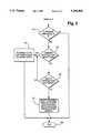
- FIGS. 4-5are flowcharts of a motion detection program for override of scheduled modes of the system of FIG. 1;
- FIG. 6is a schematic block diagram of a motion sensor of FIG. 1.
- FIG. 1there is shown an environmental control system 10, which is constructed in accordance with the present invention and which is illustrated being installed within a building 11.
- the building 11is divided into a large number of small zones or controlled spaces, such as a controlled space 46, for energy conservation purposes.
- the environmental control system 10includes a master field network controller or computer 12 having a single operator console, such as a personal computer 13 for controlling building cooling and lighting requirements by scheduling zone occupancy.
- Each zonesuch as the controlled space 46, includes a terminal unit, such as a terminal unit 40, responsive to the master computer 12 for controlling zone cooling and lighting requirements.
- the terminal unit 40includes a controller 41 having a software timer 41A responsive to the master computer 12, via a buss 15, for controlling the heating, cooling and lighting requirements of the space 46.
- Each spacesuch as the space 46 includes a lighting arrangement, such as a lighting arrangement 45 for supplying artificial light within the space 46 through the individual terminal units, such as the terminal unit 40.
- a lighting arrangementsuch as a lighting arrangement 45 for supplying artificial light within the space 46 through the individual terminal units, such as the terminal unit 40.
- a variable air volume arrangement 42having a housing 70 is mounted in a plenum space 43 above a ceiling 44 of the controlled space 46, conditions the air within the space 46.
- the lighting arrangement 45which is mounted within the space 46, supplies the space 46 with artificial lighting based upon scheduling and zone occupancy.
- the lighting arrangement 45includes at least one set of lights, such as a lighting set 47, and a motion sensor or proximity detector 49 for detecting when the controlled space 46 is occupied by one or more occupants.
- a service toolsuch as a portable computer 76A
- a service toolcan be connected electrically to a temperature sensor 76 via a jack 76B, for sending information to the controller 41.
- the service tool 76Acan set minimum and maximum flow rates for the arrangement 42 or time out periods for the lighting conditions in the space 46. It should be understood that different adjustments can be made, either under the control of the service tool 76A or the master computer 12 which is connected directly to the controller 41 via the buss 15.
- the master computer 12controls the individual terminal units, such as the terminal unit 40 based upon occupancy.
- the terminal unit 40there are three occupancy modes of operation that may be selected by either an integral system time scheduler 100 or a maintenance person (not shown) via the service tool 76A.
- Appendix Aprovides a complete source code listing for scheduler 100.
- the three occupancy modes of operationare shown in Table I as an OCCUPIED mode, a STANDBY mode, and an UNOCCUPIED mode.
- the motion sensor 49In the STANDBY mode and the UNOCCUPIED mode, the motion sensor 49 generates a signal indicative of an occupant entering or moving within the space 46 to cause the controller 41 to activate the light set 47 within the space 46.
- the controller 41When a controlled space, such as space 46, is occupied, the controller 41 causes the temperature and ventilation within the space 46 to be regulated to provide a productive and healthy environment. When the space 46 is not occupied, the controller 46 maximizes energy conservation.
- Table IIillustrates the condition of the variable air volume arrangement 42 during the three occupancy modes of operation.
- the system time scheduler 100activates the individual terminal units, such as the terminal unit 40, as well as the primary air system 48.
- a recovery periodis required to obtain heating or cooling comfort after a controlled space, such as the space 46, has been in an UNOCCUPIED state. Recovery is achieved by the master computer 12 optimizing start/stop functions to set each zone to a STANDBY state.
- Lighting for each of the controlled spacesis also controlled for the three occupancy modes of operation.
- full lightingis provided by the lighting set 47.
- the lighting set 47is dimmed to a minimum lumination level to maintain safety and psychological security.
- the dimmed lighting conditionis defined as activating one half or less of the lights available in the space, such as the space 46. Thus, if a space included two or three lights, only one light would be illuminated in the STANDBY mode. In the UNOCCUPIED mode all lighting is extinguished.
- either the master computer 12 or the space computer 76Acan cause selected individual ones of the controllers, such as the controller 41, to override lights, such as the lights 47, to dim or to fully on for cleaning or security activities.
- the override functionprovides lights and comfort whenever a space, such as the space 46 is in use. This function is called by the computer 76A or the zone mounted override device 77. Operation of the override device 77 provides lights and comfort during normal working hours and lights and comfort for a predetermined override period during nonworking hours.
- control space 46After morning warmup, individual spaces, such as the control space 46, are left in the STANDBY mode until the occupant arrives. Operation of the override device 77 signals the controller 41 to provide lights and comfort for the rest of the day.
- the override device 77may also be used to turn lights and comfort air conditioning off. This feature allows the override device 76A to appear and function as a common light switch during normal working hours and as a time limited override during non working hours.
- the lightsare flashed once presignaling that light and air conditioning will be turned off in three minutes. If an occupant desires to stay, the override device 77 may be operated to provide lights and air conditioning for the length of the override.
- the override device 77When the occupant enters the controlled space, such as the space 46 at night, operation of the override device 77 provides lights and comfort for the occupancy. At the end of any override period, the lights will be flashed presignaling that lights and air conditioning will be turned off. The occupant may again operate the override device or leave the work place.
- each zone controllersuch as the zone controller 41 is downloaded from the master computer 12 with a given energy conversation schedule based upon occupant utilization of the zone, such as the space 46.
- Each zone energy conservation scheduleis unique and considers space utilization during scheduled and non-scheduled working hours.
- the motion detector 49generates a pulse signal which is coupled to the zone controller timer, such as the timer 41A.
- the timer 41Ais a retriggerable timer which is reset to a predetermined count-down time period each time a pulse is received from the motion detector 49. Thus, if the count-down period is set for 5 minutes for example, each time a pulse is received the timer 41A will be reset to its 5 minute count-down period.
- the motion detector 49In operation, when an occupant arrives at a zone, such as the space 46, the motion detector 49 generates a pulse causing the controller timer, such as the timer 41A, to be reset to its predetermined count-down time period.
- the controller 41causes the lighting arrangement 45 to be activated for supplying the space 46 with artificial light. In this regard, the space 46 will be illuminated with the maximum amount of artificial light available from the lighting arrangement 45.
- the energy conservation schedulecauses the count-down timer 41A to be set to predetermined time periods that help prevent false triggering or shut-downs relative to occupant activity.
- nighttime settings for the timer 41Aare substantially shorter than daytime periods because during nighttime hours any activity within a zone usually is caused by cleaning or janitor personnel who are very active.
- time settingsare typically set to longer periods of time.
- Table IVis a typical schedule for an individual space, such as the space 46.
- the master computer 12may download operating schedules or commands to each controller, such as the controller 41. Controllers may share the same schedule or have a unique schedules depending upon occupant requirements. The primary objective of scheduling is to conserve energy and to help prevent false accidental switching from OCCUPIED/STANDBY modes to UNOCCUPIED modes.
- the timing schedule of Table IVis illustrative to accommodate the use requirements of a given occupant.
- the nighttime setting 1800 hours to 0700 hoursare short as cleaning activities may be scheduled. Cleaning people create more motion in the individual spaces and typically do not remain in any given space for an extended period of time.
- the timermay be reduced during periods where an office worker is more active, such as a lunch period or a break.
- each local controllersuch as the controller 41
- the time periods programmed into each local controlleris adjustable from 1 second to 255 minutes. This time period may be set remotely by a service operator from the console 13 or by a service operator within the space 46 via the service tool 76A.
- each timersuch as timer 41A to a short period, such as a two minute period and places the controller 41 in an unoccupied mode state. Thus, all lights and air conditioning within the space 46 will be turned off.
- the timer 41Awill be set to a short period, such as two minutes, but the controller will be placed in a STANDBY mode. In this regard, instead of the air conditioning and lights being completely turned off, they will be set to occupied temperature and minimum luminance levels. Thus, a space will not be cold and completely dark when the janitor or security persons enter the space. Moreover, once the person enters the space, the motion detector will cause the controller to activate the lighting set 47 to its full luminance level.
- the predetermined time periodsmay be dynamically set by time function or other events. This permits the time period to be reduced to optimize energy saving opportunities based upon occupant use of the controlled space 46. In this regard, the time period may be increased during normal working hours to reduce false turn off or shut-down conditions. Also, lights are dimmed when the space 46 is vacated during the day time scheduled hours. Lights are turned off when the space 46 is vacated during the evening non-scheduled hours.
- the system 10includes a primary air system 48 for supplying cold air through the individual terminal units, such as the terminal unit 40, to the individual controlled spaces, such as the space 46.
- the primary air system 48includes a primary air fan 51 which draws air from a mixed air plenum or duct through a motor-driven damper arrangement 53 and 59, and which discharges it through a cooling coil 55 to supply cool primary air to the terminal units, such as the terminal unit 40.
- the cooled primary airflows into the series connected terminal units, such as unit 40 for each space, such as the space 46.
- the other terminal unitsare not shown, but are similar to unit 40.
- a return air fan 57draws air returned from the spaces being conditioned, and discharges it through the motor driven damper 59 and into the inlet of the fan 51 for mixing with entering outside air. Also, a motor driven damper 61 discharges return air from the discharge of fan 57, to the outside environment when required.
- the arrangement 42includes a motor driven damper 63 for admitting the primary air under pressure into an inlet of a series connected terminal fan 67.
- the terminal fan 67draws both the primary air under pressure via an inlet 42B, and air returned from the space 46 via an inlet 42A.
- a chamber 42C of the arrangement 42houses the fan 67, and includes the inlets 42A and 42B.
- the series fan 67discharges air via an outlet 42D of the chamber 42C, into the interior of an adjacent chamber 68 of the arrangement 42, and from there, the air flows out of an outlet 68A of the chamber 68, through a heating coil 65 and into the space 46.
- the heating coilis optional, and thus, may be omitted, if desired.
- the return air drawn from the space 46can either be from the interior of the plenum above the ceiling 44, or it can be guided by duct (not shown).
- the discharge of the fan 67is directed into the chamber 68 within the terminal 40 for causing the flow of primary air and return air to enter the controlled space 46 via the heating coil 65.
- the cold primary airis mixed by the fan 67 with the return air from the space 46, and the mixed air is heated, if required, by the heating coil 65, prior to being discharged into the space 46.
- the primary air system 48supplies a variable volume of cooled air which is distributed to each of the terminal units, such as the terminal unit 40, the volume of air available to each of the terminal units is of variable quantity depending upon the demand requirements of each of the terminal units.
- the controller 41is mounted outside of the housing 70 of the terminal unit 40, which in turn is disposed in relatively close proximity to the space 46.
- the controller 41monitors continuously a set of variable conditions of the air in the space 46, the volume of primary air available to the terminal unit 40, the condition of the air in the space 46, and the presence or lack of presence of individuals within the space 46.
- the controller 41generates a continuously varying control signal indicative of a desired quantity of cooled primary air under pressure required for mixing with return air from the controlled space 46 in mixing chamber 68 for the purpose of conditioning the air in the space 46 to a desired temperature.
- a fiberoptic link or light conduit 71is interconnected between the controller 41 and a fan control unit 73 forming part of the variable air volume arrangement 42.
- the fan control 73is also mounted on the outside of the housing 70 above the fan 67 mounted on the inside of the housing 70 within the chamber 42C.
- the fan control 73responds to the control signals received from the controller 41, via the fiberoptic link 71, to cause the motor device in the form of the fan 67, to vary continuously the flow rate of the air entering the mixing chamber 68 during cooling, for conditioning the air being discharged into the space 46.
- the controller 41causes a control signal to vary in a proportional manner relative to the volume of primary air available to the terminal unit 40 for conditioning the air being discharged into the space 46.
- the fan control 73responds to the control signals received via the fiberoptic link 71 to provide a high voltage continuously during the pulse modulated signal via a lead 74 to a motor 75 driving the fan 67 continuously in a manner described therein.
- the controller 41generates the control signal sent via the fiberoptic link 71 to the fan control 73, in response to a set of variables.
- a temperature sensor 76 disposed within the space 46provides a signal to the controller 41, which signal is indicative of the temperature of the air within the space 46.
- the sensor 76is also used for sending a desired temperature for the space 46, and for disabling an automatic shut-down feature that will be described.
- an override on/off switch 77enables an occupant (not shown) to disable or override the scheduled air conditioning and lighting functions stored within the controller 41.
- the occupantcan activate lighting and air conditioning for a particular space, such as the space 46, via the on/off switch 77.
- a duct 81 conveying the cool primary air under pressure into the terminal unit 40has an air flow sensor 80 mounted thereto with an element 80A to provide an air volume signal to the controller 41.
- the air volume signalis indicative of the volume of cool primary air available for drawing into the terminal unit 40.
- the temperature of the primary airmay typically be 55° F., and it mixes in the mixing chamber 68 with the return air from the return space 46 at, for example, a higher temperature.
- a main air valve or damper 63Ais controlled by the electric damper motor 63 in response to a signal received via the lead 63B from the controller 41.
- the signal for driving the motor 63depends on the other conditions being monitored by the controller 41.
- a fiberoptic link or light conduit 65Aconveys a continuous signal from the controller 41 to heating element 65.
- the element 65is driven by the signal to modulate the amount of heating of the air being discharged into the space 46.
- the override functionbegins with an "on" operation of the computer 76A.
- the computer 76Asets an override timer 41A (FIG. 2) in the controller 41 to a user defined time, typically 60 minutes. Each minute, the controller 41 subtracts one minute from the override timer. Any time the override timer is greater than 0 minutes, the occupancy mode is ignored allowing zone lighting and air conditioning to be controlled as if the mode was the OCCUPIED mode.
- the controller 41changes the occupancy mode as shown in Table III. This allows the occupants to turn on lights and air conditioning from the space 46. During normal working hours, lights and air conditioning are left on for the rest of the day. If the override timer expires during nonworking hours, lights and air conditioning are turned off at the end of the override period to disable energy utilization.
- the overridemay expire when the overtimer reaches zero, or alternately, the override device 77 may be connected to terminate the override period.
- the lighting arrangement 45is connected to the controller 41 by a pair of cables 83 and 84 respectively.
- cable 83is connected to the motion detector 49, while cable 84 is connected to the lighting set 47.
- Cable 84includes a pair of conductors 85 and 86 for a lighting relay 97 and a standby relay 99 that will be described hereinafter
- the lighting set 47includes a set of illumination devices, such as a fluorescent bulb 90 and 90A connected to a pair of ballast units 92 and 92A respectively.
- the ballast units 92 and 92Aare controlled by a pair of relay 94 and 96 respectively via the lighting relay 97 and the standby relay 99.
- the lighting relay 97 and the standby relay 99are connected to the controller 41 via the cable 84 and respond to the control signals generated by the controller 41.
- relay 97is a lighting relay for causing full power to be applied to the bulbs 90 and 90A when the controller 41 is in the OCCUPIED mode.
- Relay 96is a standby relay for causing the bulb 90A to be extinguished, thus dimming the lighting when the controller 41 is in the STANDBY MODE.
- the lighting relay 94 and standby relay 96are each 20 amp, 277 VAC ballast load relays manufactured by Staefa Control System under part No. SM2-LMAIN.
- the motion sensor 49is an infrared motion sensor.
- the motion sensoris sold under the trademark name of SureshotTM and is a 6250 series manufactured by Sentrol.
- the motion sensor 49includes an operational amplifier 602 having its positive input connected to an infrared sensor 604 via a current limiting resistor 605.
- the negative input of amplifier 602is coupled to a digital to analog converter 607 via a current limiting resistor 603.
- the input to the digital to analog converter 607is controlled by a digital potentiometer 606 which, under the control of the controller 41, may be adjusted to increase or decrease the sensitivity of the motion sensor 49.
- An analog to digital converter 608translates the analog output of the motion sensor 49 to a digital signal for processing by the controller 41.
- the temperature sensor 76is sold and manufactured by Staefa Control System under part number 598-63010-05.
- the service tool 76Aincludes a housing 300, a microprocessor 301, a numeric keypad 302, and a function keypad 304 having on and off keys 306 and 308 respectively.
- a liquid crystal display panel 310enables a service operator to visualize the time-out periods previously stored in the system 10 and to verify entries made via the respective keypads 302 and 304.
- An RS232 interface (not shown) and convention RJ12 telephone jack 312enable the service tool 76A to be connected electrically into the temperature sensor jack 76B.
- the service toolis sold by Staefa Control System under part number 598-63010-01.
- the scheduler program 100which is fully described in Appendix A attached hereto includes a motion detect program 102 for override of the scheduled modes of the system 10.
- the motion detect program 102will be described hereinafter in greater detail and is located in Appendix "A” under the "1 minute applications” and “input probe formulas” sections.
- the motion detect program 102begins at an instruction box 110 (FIG. 4) which instructs the controller 41 to process any digital signal received from the motion detector 49.
- the programthen advances to a decision instruction 112 to determine whether or not the motion detector 49 has generated an output signal indicative of detected motion within the space, such as the space 46.
- the programgoes to an instruction box 114 which sets the previous sensor state to off.
- the programgoes to an instruction box 120 which causes the override timer 41A to be decremented once every minute.
- the programadvances to a decision instruction 115 which determines whether or not the previous state of the motion sensor 49 was off indicating that motion was not detected. If the previous state of the motion sensor 49 was off, the program goes to an instruction box 117 which causes the override timer 41A to be reset to its default override time. After execution, of the command at instruction box 117, the program goes to an instruction box 119 which sets the previous sensor state to ON.
- the programadvances to an instruction box 119 and proceeds as previously described. From instruction box 119, the program advances to instruction box 120 and provides as previously described by decrementing the override timer 41A every minute.
- the programproceeds to a decision instruction 124 which determines whether or not the motion detector type input has been found. If the type input has not been found, the program advances to a decision instruction 126 which determines whether or not the previous state of the controller 41 was the STANDBY state.
- the programgoes to an instruction box 127 which causes the controller 41 to be returned to the host downloaded occupancy mode.
- the programthen advances to the end instruction at 130.
- the programgoes to an instruction box 128 which modifies the controller occupancy mode from the STANDBY mode to the OCCUPIED mode. The program then proceeds to the end instruction at 130.
Landscapes
- Engineering & Computer Science (AREA)
- Chemical & Material Sciences (AREA)
- Combustion & Propulsion (AREA)
- Mechanical Engineering (AREA)
- General Engineering & Computer Science (AREA)
- Human Computer Interaction (AREA)
- Signal Processing (AREA)
- Physics & Mathematics (AREA)
- Fuzzy Systems (AREA)
- Mathematical Physics (AREA)
- Air Conditioning Control Device (AREA)
Abstract
Description
TABLE I ______________________________________ OCCUPIED Determined when occupants are in a controlled space during scheduled work periods. STANDBY Determined when a controlled space is occupied during scheduled periods. UNOCCUPIED Determined when a controlled space is scheduled for nonoccupancy during overnight and weekend periods. ______________________________________
TABLE II ______________________________________ OCCUPIEDController 41 causes the temperature in thespace 46 to be precisely controlled to occupied setpoints and ventilation rates to ensure indoor air quality. STANDBY Thespace 46 may be occupied at any time. Accordingly, temperature setpoints are precisely controlled to the occupied setpoints. Ventilation is reduced or eliminated to help save energy and prevent overcooling of thespace 46.UNOCCUPIED Controller 41 causes the temperature in the space to be controlled to unoccupied setpoints. Ventilation is eliminated to save energy. ______________________________________
TABLE IV ______________________________________ TIMER SETTINGS (MINUTES) DAYS/ HOURS MON TUE WED THU FRI SAT SUN ______________________________________ 0000 2 2 2 2 2 2 2 0100 2 2 2 2 2 2 2 0200 2 2 2 2 2 2 2 0300 2 2 2 2 2 2 2 0400 2 2 2 2 2 2 2 0500 2 2 2 2 2 2 2 0600 5 5 5 5 5 5 5 0700 5 5 5 5 5 5 5 0800 10 10 10 10 10 15 15 0900 15 15 15 15 15 15 15 1000 15 15 15 15 15 15 15 1100 10 10 10 10 10 15 15 1200 5 5 5 5 5 15 15 1300 10 10 10 10 10 15 15 1400 15 15 15 15 15 15 15 1500 15 15 15 15 15 15 15 1600 10 10 10 10 10 15 15 1700 10 10 10 10 10 2 2 1800 5 5 5 5 5 2 2 1900 5 5 5 5 5 2 2 2000 5 5 5 5 5 2 2 2100 5 5 5 5 5 2 2 2200 2 5 5 5 5 2 2 2300 2 2 2 2 2 5 5 ______________________________________
TABLE III ______________________________________ Timer > 0 Timer = 0 Mode Mode OCCUPIED OCCUPIED STANDBY STANDBY UNOCCUPIED UNOCCUPIED Occupancy Mode Ignored ______________________________________
Claims (21)
Priority Applications (1)
| Application Number | Priority Date | Filing Date | Title |
|---|---|---|---|
| US08/048,494US5344068A (en) | 1993-04-16 | 1993-04-16 | Dynamically controlled environmental control system |
Applications Claiming Priority (1)
| Application Number | Priority Date | Filing Date | Title |
|---|---|---|---|
| US08/048,494US5344068A (en) | 1993-04-16 | 1993-04-16 | Dynamically controlled environmental control system |
Publications (1)
| Publication Number | Publication Date |
|---|---|
| US5344068Atrue US5344068A (en) | 1994-09-06 |
Family
ID=21954888
Family Applications (1)
| Application Number | Title | Priority Date | Filing Date |
|---|---|---|---|
| US08/048,494Expired - LifetimeUS5344068A (en) | 1993-04-16 | 1993-04-16 | Dynamically controlled environmental control system |
Country Status (1)
| Country | Link |
|---|---|
| US (1) | US5344068A (en) |
Cited By (98)
| Publication number | Priority date | Publication date | Assignee | Title |
|---|---|---|---|---|
| US6073110A (en)* | 1997-07-22 | 2000-06-06 | Siemens Building Technologies, Inc. | Activity based equipment scheduling method and system |
| US6366832B2 (en)* | 1998-11-24 | 2002-04-02 | Johnson Controls Technology Company | Computer integrated personal environment system |
| US20050047279A1 (en)* | 2003-08-27 | 2005-03-03 | Fuji Photo Film Co., Ltd. | Calendar timer mechanism, medical image processing system, and control program |
| US20050119766A1 (en)* | 2003-12-02 | 2005-06-02 | Amundson John B. | Controller interface with menu schedule override |
| EP1562408A1 (en) | 2004-02-06 | 2005-08-10 | Patent-Treuhand-Gesellschaft für elektrische Glühlampen mbH | Electronic ballast with timer-based correction |
| US20080283621A1 (en)* | 2007-05-16 | 2008-11-20 | Inncom International, Inc. | Occupant controlled energy management system and method for managing energy consumption in a multi-unit building |
| GB2449498A (en)* | 2007-05-25 | 2008-11-26 | Stephen Edward Ellwood | Heating system for retrofitting to a building |
| US20090138131A1 (en)* | 2007-10-22 | 2009-05-28 | Zodiac Pool Systems, Inc. | Residential Environmental Management control System with Sprinkler Control Module |
| US20090143917A1 (en)* | 2007-10-22 | 2009-06-04 | Zodiac Pool Systems, Inc. | Residential Environmental Management Control System Interlink |
| US20090164049A1 (en)* | 2007-12-20 | 2009-06-25 | Zodiac Pool Systems, Inc. | Residential Environmental Management Control System with Automatic Adjustment |
| US20090266904A1 (en)* | 2008-04-24 | 2009-10-29 | International Business Machines Corporation | Hvac system with energy saving modes set using a security system control panel |
| EP2014994A3 (en)* | 2007-05-22 | 2010-12-22 | Robin Graham | Distributed Temperature Control System |
| US7926975B2 (en) | 2007-12-21 | 2011-04-19 | Altair Engineering, Inc. | Light distribution using a light emitting diode assembly |
| US7938562B2 (en) | 2008-10-24 | 2011-05-10 | Altair Engineering, Inc. | Lighting including integral communication apparatus |
| US20110118857A1 (en)* | 2009-12-02 | 2011-05-19 | Eric Bodnar | Method and apparatus for automation of a programmable device |
| US7946729B2 (en) | 2008-07-31 | 2011-05-24 | Altair Engineering, Inc. | Fluorescent tube replacement having longitudinally oriented LEDs |
| US20110140914A1 (en)* | 2008-11-24 | 2011-06-16 | Midori Technologies Ltd. | Controller system |
| US7976196B2 (en) | 2008-07-09 | 2011-07-12 | Altair Engineering, Inc. | Method of forming LED-based light and resulting LED-based light |
| US8000314B2 (en) | 1996-12-06 | 2011-08-16 | Ipco, Llc | Wireless network system and method for providing same |
| US8013732B2 (en) | 1998-06-22 | 2011-09-06 | Sipco, Llc | Systems and methods for monitoring and controlling remote devices |
| US20110221271A1 (en)* | 2010-03-10 | 2011-09-15 | Eric Bodnar | Signal Variance Sensing Power Controller |
| US8031650B2 (en) | 2004-03-03 | 2011-10-04 | Sipco, Llc | System and method for monitoring remote devices with a dual-mode wireless communication protocol |
| US8064412B2 (en) | 1998-06-22 | 2011-11-22 | Sipco, Llc | Systems and methods for monitoring conditions |
| US8102799B2 (en) | 2006-10-16 | 2012-01-24 | Assa Abloy Hospitality, Inc. | Centralized wireless network for multi-room large properties |
| US8118447B2 (en) | 2007-12-20 | 2012-02-21 | Altair Engineering, Inc. | LED lighting apparatus with swivel connection |
| US8171136B2 (en) | 2001-10-30 | 2012-05-01 | Sipco, Llc | System and method for transmitting pollution information over an integrated wireless network |
| US8214084B2 (en) | 2008-10-24 | 2012-07-03 | Ilumisys, Inc. | Integration of LED lighting with building controls |
| US8256924B2 (en) | 2008-09-15 | 2012-09-04 | Ilumisys, Inc. | LED-based light having rapidly oscillating LEDs |
| CN102741767A (en)* | 2009-12-21 | 2012-10-17 | 松下电器产业株式会社 | Energy conservation analysis system |
| US8299695B2 (en) | 2009-06-02 | 2012-10-30 | Ilumisys, Inc. | Screw-in LED bulb comprising a base having outwardly projecting nodes |
| US20120290231A1 (en)* | 2009-12-21 | 2012-11-15 | Panasonic Corporation | Energy conservation diagnosis system |
| US8324817B2 (en) | 2008-10-24 | 2012-12-04 | Ilumisys, Inc. | Light and light sensor |
| US8330381B2 (en) | 2009-05-14 | 2012-12-11 | Ilumisys, Inc. | Electronic circuit for DC conversion of fluorescent lighting ballast |
| US8362710B2 (en) | 2009-01-21 | 2013-01-29 | Ilumisys, Inc. | Direct AC-to-DC converter for passive component minimization and universal operation of LED arrays |
| US8360599B2 (en) | 2008-05-23 | 2013-01-29 | Ilumisys, Inc. | Electric shock resistant L.E.D. based light |
| US8410931B2 (en) | 1998-06-22 | 2013-04-02 | Sipco, Llc | Mobile inventory unit monitoring systems and methods |
| US8421366B2 (en) | 2009-06-23 | 2013-04-16 | Ilumisys, Inc. | Illumination device including LEDs and a switching power control system |
| US8446884B2 (en) | 2004-03-03 | 2013-05-21 | Sipco, Llc | Dual-mode communication devices, methods and systems |
| US8444292B2 (en) | 2008-10-24 | 2013-05-21 | Ilumisys, Inc. | End cap substitute for LED-based tube replacement light |
| US8454193B2 (en) | 2010-07-08 | 2013-06-04 | Ilumisys, Inc. | Independent modules for LED fluorescent light tube replacement |
| US8489063B2 (en) | 2001-10-24 | 2013-07-16 | Sipco, Llc | Systems and methods for providing emergency messages to a mobile device |
| US8523394B2 (en) | 2010-10-29 | 2013-09-03 | Ilumisys, Inc. | Mechanisms for reducing risk of shock during installation of light tube |
| US8540401B2 (en) | 2010-03-26 | 2013-09-24 | Ilumisys, Inc. | LED bulb with internal heat dissipating structures |
| US8541958B2 (en) | 2010-03-26 | 2013-09-24 | Ilumisys, Inc. | LED light with thermoelectric generator |
| US8556452B2 (en) | 2009-01-15 | 2013-10-15 | Ilumisys, Inc. | LED lens |
| US8596813B2 (en) | 2010-07-12 | 2013-12-03 | Ilumisys, Inc. | Circuit board mount for LED light tube |
| US8653984B2 (en) | 2008-10-24 | 2014-02-18 | Ilumisys, Inc. | Integration of LED lighting control with emergency notification systems |
| US8666357B2 (en) | 2001-10-24 | 2014-03-04 | Sipco, Llc | System and method for transmitting an emergency message over an integrated wireless network |
| US8664880B2 (en) | 2009-01-21 | 2014-03-04 | Ilumisys, Inc. | Ballast/line detection circuit for fluorescent replacement lamps |
| US8674626B2 (en) | 2008-09-02 | 2014-03-18 | Ilumisys, Inc. | LED lamp failure alerting system |
| US8787246B2 (en) | 2009-02-03 | 2014-07-22 | Ipco, Llc | Systems and methods for facilitating wireless network communication, satellite-based wireless network systems, and aircraft-based wireless network systems, and related methods |
| US8866396B2 (en) | 2000-02-11 | 2014-10-21 | Ilumisys, Inc. | Light tube and power supply circuit |
| US8870415B2 (en) | 2010-12-09 | 2014-10-28 | Ilumisys, Inc. | LED fluorescent tube replacement light with reduced shock hazard |
| US8901823B2 (en) | 2008-10-24 | 2014-12-02 | Ilumisys, Inc. | Light and light sensor |
| US8924588B2 (en) | 1999-03-18 | 2014-12-30 | Sipco, Llc | Systems and methods for controlling communication between a host computer and communication devices |
| US8964708B2 (en) | 1998-06-22 | 2015-02-24 | Sipco Llc | Systems and methods for monitoring and controlling remote devices |
| US20150136378A1 (en)* | 2012-06-22 | 2015-05-21 | Mitsubishi Electric Corporation | Air-conditioning system |
| US9057493B2 (en) | 2010-03-26 | 2015-06-16 | Ilumisys, Inc. | LED light tube with dual sided light distribution |
| US9072171B2 (en) | 2011-08-24 | 2015-06-30 | Ilumisys, Inc. | Circuit board mount for LED light |
| US9163794B2 (en) | 2012-07-06 | 2015-10-20 | Ilumisys, Inc. | Power supply assembly for LED-based light tube |
| US9184518B2 (en) | 2012-03-02 | 2015-11-10 | Ilumisys, Inc. | Electrical connector header for an LED-based light |
| US9224115B2 (en) | 2012-05-23 | 2015-12-29 | Infosys Limited | Information technology energy wastage management system |
| US9267650B2 (en) | 2013-10-09 | 2016-02-23 | Ilumisys, Inc. | Lens for an LED-based light |
| US9271367B2 (en) | 2012-07-09 | 2016-02-23 | Ilumisys, Inc. | System and method for controlling operation of an LED-based light |
| US9285084B2 (en) | 2013-03-14 | 2016-03-15 | Ilumisys, Inc. | Diffusers for LED-based lights |
| US9439126B2 (en) | 2005-01-25 | 2016-09-06 | Sipco, Llc | Wireless network protocol system and methods |
| US9510400B2 (en) | 2014-05-13 | 2016-11-29 | Ilumisys, Inc. | User input systems for an LED-based light |
| US9574717B2 (en) | 2014-01-22 | 2017-02-21 | Ilumisys, Inc. | LED-based light with addressed LEDs |
| US9903606B2 (en) | 2014-04-29 | 2018-02-27 | Vivint, Inc. | Controlling parameters in a building |
| US10001791B2 (en) | 2012-07-27 | 2018-06-19 | Assa Abloy Ab | Setback controls based on out-of-room presence information obtained from mobile devices |
| US10050948B2 (en) | 2012-07-27 | 2018-08-14 | Assa Abloy Ab | Presence-based credential updating |
| US10126009B2 (en) | 2014-06-20 | 2018-11-13 | Honeywell International Inc. | HVAC zoning devices, systems, and methods |
| US10161568B2 (en) | 2015-06-01 | 2018-12-25 | Ilumisys, Inc. | LED-based light with canted outer walls |
| US10197979B2 (en) | 2014-05-30 | 2019-02-05 | Vivint, Inc. | Determining occupancy with user provided information |
| US20190134443A1 (en)* | 2014-11-05 | 2019-05-09 | WWTemplar LLC | Remote Control of Fire Suppression Systems |
| US10440801B1 (en)* | 2018-08-07 | 2019-10-08 | Abl Ip Holding Llc | Multi-mode occupancy sensor and lighting system control |
| US10477640B2 (en) | 2009-10-08 | 2019-11-12 | Delos Living Llc | LED lighting system |
| US10599116B2 (en) | 2014-02-28 | 2020-03-24 | Delos Living Llc | Methods for enhancing wellness associated with habitable environments |
| CN111156186A (en)* | 2019-12-31 | 2020-05-15 | 深圳粤鹏环保技术股份有限公司 | One-use one-standby two-equipment local/remote start-stop control circuit and method |
| US10691423B2 (en) | 2018-04-04 | 2020-06-23 | Johnson Controls Technology Company | Testing systems and methods for performing HVAC zone airflow adjustments |
| US10691148B2 (en) | 2012-08-28 | 2020-06-23 | Delos Living Llc | Systems, methods and articles for enhancing wellness associated with habitable environments |
| US20200344693A1 (en)* | 2017-12-20 | 2020-10-29 | Roomz S.A. | A battery-operated monitoring device, system and method |
| US10837666B2 (en) | 2015-07-01 | 2020-11-17 | National Ict Australia Limited | Controlling operation of energy-consuming devices |
| US10923226B2 (en) | 2015-01-13 | 2021-02-16 | Delos Living Llc | Systems, methods and articles for monitoring and enhancing human wellness |
| US11099533B2 (en) | 2014-05-07 | 2021-08-24 | Vivint, Inc. | Controlling a building system based on real time events |
| US20210366253A1 (en)* | 2020-03-06 | 2021-11-25 | Ecolink Intelligent Technology, Inc. | Person detection apparatus and method |
| CN114183859A (en)* | 2021-12-10 | 2022-03-15 | 珠海格力电器股份有限公司 | Ice storage system, control method and air conditioner |
| US11338107B2 (en) | 2016-08-24 | 2022-05-24 | Delos Living Llc | Systems, methods and articles for enhancing wellness associated with habitable environments |
| WO2022262370A1 (en)* | 2021-06-15 | 2022-12-22 | 青岛海尔空调器有限总公司 | Method and apparatus for controlling air conditioner, and air conditioner |
| US11649977B2 (en) | 2018-09-14 | 2023-05-16 | Delos Living Llc | Systems and methods for air remediation |
| US11668481B2 (en) | 2017-08-30 | 2023-06-06 | Delos Living Llc | Systems, methods and articles for assessing and/or improving health and well-being |
| US20230375203A1 (en)* | 2018-05-17 | 2023-11-23 | Johnson Controls Tyco IP Holdings LLP | Climate control adaptive temperature setpoint adjustment systems and methods |
| US11836030B2 (en) | 2018-12-31 | 2023-12-05 | Ecolink Intelligent Technology, Inc. | User-configurable person detection system, method and apparatus |
| US11844163B2 (en) | 2019-02-26 | 2023-12-12 | Delos Living Llc | Method and apparatus for lighting in an office environment |
| US11900781B2 (en) | 2019-03-13 | 2024-02-13 | Ecolink Intelligent Technology, Inc. | Auto-configurable motion/occupancy sensor |
| US11898898B2 (en) | 2019-03-25 | 2024-02-13 | Delos Living Llc | Systems and methods for acoustic monitoring |
| RU2824535C1 (en)* | 2023-09-21 | 2024-08-09 | Юрий Георгиевич Пестерев | Method of controlling climate parameters in separate rooms by means of air climatic systems and ventilation systems with mechanical air movement |
| US12146793B2 (en) | 2021-07-22 | 2024-11-19 | Ecolink Intelligent Technology, Inc. | Adjustable dwell time for motion detector based on activity |
Citations (6)
| Publication number | Priority date | Publication date | Assignee | Title |
|---|---|---|---|---|
| US4223831A (en)* | 1979-02-21 | 1980-09-23 | Szarka Jay R | Sound activated temperature control system |
| US4462540A (en)* | 1981-09-19 | 1984-07-31 | Allen-Martin Electronics Limited | Control system for an air temperature changing unit |
| US4623969A (en)* | 1983-01-07 | 1986-11-18 | David Bensoussan | Electronic temperature controller for householding |
| US4997029A (en)* | 1985-12-27 | 1991-03-05 | Mitsubishi Denki Kabushiki Kaisha | Air conditioning apparatus |
| US5088645A (en)* | 1991-06-24 | 1992-02-18 | Ian Bell | Self-programmable temperature control system for a heating and cooling system |
| US5127575A (en)* | 1991-04-15 | 1992-07-07 | Beerbaum Ronald H | Supervisory control unit for electrical equipment |
- 1993
- 1993-04-16USUS08/048,494patent/US5344068A/ennot_activeExpired - Lifetime
Patent Citations (6)
| Publication number | Priority date | Publication date | Assignee | Title |
|---|---|---|---|---|
| US4223831A (en)* | 1979-02-21 | 1980-09-23 | Szarka Jay R | Sound activated temperature control system |
| US4462540A (en)* | 1981-09-19 | 1984-07-31 | Allen-Martin Electronics Limited | Control system for an air temperature changing unit |
| US4623969A (en)* | 1983-01-07 | 1986-11-18 | David Bensoussan | Electronic temperature controller for householding |
| US4997029A (en)* | 1985-12-27 | 1991-03-05 | Mitsubishi Denki Kabushiki Kaisha | Air conditioning apparatus |
| US5127575A (en)* | 1991-04-15 | 1992-07-07 | Beerbaum Ronald H | Supervisory control unit for electrical equipment |
| US5088645A (en)* | 1991-06-24 | 1992-02-18 | Ian Bell | Self-programmable temperature control system for a heating and cooling system |
Cited By (202)
| Publication number | Priority date | Publication date | Assignee | Title |
|---|---|---|---|---|
| US8982856B2 (en) | 1996-12-06 | 2015-03-17 | Ipco, Llc | Systems and methods for facilitating wireless network communication, satellite-based wireless network systems, and aircraft-based wireless network systems, and related methods |
| US8000314B2 (en) | 1996-12-06 | 2011-08-16 | Ipco, Llc | Wireless network system and method for providing same |
| US8233471B2 (en) | 1996-12-06 | 2012-07-31 | Ipco, Llc | Wireless network system and method for providing same |
| US8625496B2 (en) | 1996-12-06 | 2014-01-07 | Ipco, Llc | Wireless network system and method for providing same |
| US6073110A (en)* | 1997-07-22 | 2000-06-06 | Siemens Building Technologies, Inc. | Activity based equipment scheduling method and system |
| US8410931B2 (en) | 1998-06-22 | 2013-04-02 | Sipco, Llc | Mobile inventory unit monitoring systems and methods |
| US9129497B2 (en) | 1998-06-22 | 2015-09-08 | Statsignal Systems, Inc. | Systems and methods for monitoring conditions |
| US8064412B2 (en) | 1998-06-22 | 2011-11-22 | Sipco, Llc | Systems and methods for monitoring conditions |
| US8212667B2 (en) | 1998-06-22 | 2012-07-03 | Sipco, Llc | Automotive diagnostic data monitoring systems and methods |
| US9691263B2 (en) | 1998-06-22 | 2017-06-27 | Sipco, Llc | Systems and methods for monitoring conditions |
| US9571582B2 (en) | 1998-06-22 | 2017-02-14 | Sipco, Llc | Systems and methods for monitoring and controlling remote devices |
| US9430936B2 (en) | 1998-06-22 | 2016-08-30 | Sipco Llc | Systems and methods for monitoring and controlling remote devices |
| US8013732B2 (en) | 1998-06-22 | 2011-09-06 | Sipco, Llc | Systems and methods for monitoring and controlling remote devices |
| US8223010B2 (en) | 1998-06-22 | 2012-07-17 | Sipco Llc | Systems and methods for monitoring vehicle parking |
| US8964708B2 (en) | 1998-06-22 | 2015-02-24 | Sipco Llc | Systems and methods for monitoring and controlling remote devices |
| US6366832B2 (en)* | 1998-11-24 | 2002-04-02 | Johnson Controls Technology Company | Computer integrated personal environment system |
| US8924587B2 (en) | 1999-03-18 | 2014-12-30 | Sipco, Llc | Systems and methods for controlling communication between a host computer and communication devices |
| US8924588B2 (en) | 1999-03-18 | 2014-12-30 | Sipco, Llc | Systems and methods for controlling communication between a host computer and communication devices |
| US8930571B2 (en) | 1999-03-18 | 2015-01-06 | Sipco, LLP | Systems and methods for controlling communication between a host computer and communication devices |
| US9006993B1 (en) | 2000-02-11 | 2015-04-14 | Ilumisys, Inc. | Light tube and power supply circuit |
| US9752736B2 (en) | 2000-02-11 | 2017-09-05 | Ilumisys, Inc. | Light tube and power supply circuit |
| US9006990B1 (en) | 2000-02-11 | 2015-04-14 | Ilumisys, Inc. | Light tube and power supply circuit |
| US10557593B2 (en) | 2000-02-11 | 2020-02-11 | Ilumisys, Inc. | Light tube and power supply circuit |
| US9416923B1 (en) | 2000-02-11 | 2016-08-16 | Ilumisys, Inc. | Light tube and power supply circuit |
| US9739428B1 (en) | 2000-02-11 | 2017-08-22 | Ilumisys, Inc. | Light tube and power supply circuit |
| US10054270B2 (en) | 2000-02-11 | 2018-08-21 | Ilumisys, Inc. | Light tube and power supply circuit |
| US8870412B1 (en) | 2000-02-11 | 2014-10-28 | Ilumisys, Inc. | Light tube and power supply circuit |
| US9222626B1 (en) | 2000-02-11 | 2015-12-29 | Ilumisys, Inc. | Light tube and power supply circuit |
| US8866396B2 (en) | 2000-02-11 | 2014-10-21 | Ilumisys, Inc. | Light tube and power supply circuit |
| US9746139B2 (en) | 2000-02-11 | 2017-08-29 | Ilumisys, Inc. | Light tube and power supply circuit |
| US9759392B2 (en) | 2000-02-11 | 2017-09-12 | Ilumisys, Inc. | Light tube and power supply circuit |
| US9777893B2 (en) | 2000-02-11 | 2017-10-03 | Ilumisys, Inc. | Light tube and power supply circuit |
| US9803806B2 (en) | 2000-02-11 | 2017-10-31 | Ilumisys, Inc. | Light tube and power supply circuit |
| US9970601B2 (en) | 2000-02-11 | 2018-05-15 | Ilumisys, Inc. | Light tube and power supply circuit |
| US9282029B2 (en) | 2001-10-24 | 2016-03-08 | Sipco, Llc. | System and method for transmitting an emergency message over an integrated wireless network |
| US10149129B2 (en) | 2001-10-24 | 2018-12-04 | Sipco, Llc | Systems and methods for providing emergency messages to a mobile device |
| US8666357B2 (en) | 2001-10-24 | 2014-03-04 | Sipco, Llc | System and method for transmitting an emergency message over an integrated wireless network |
| US8489063B2 (en) | 2001-10-24 | 2013-07-16 | Sipco, Llc | Systems and methods for providing emergency messages to a mobile device |
| US9615226B2 (en) | 2001-10-24 | 2017-04-04 | Sipco, Llc | System and method for transmitting an emergency message over an integrated wireless network |
| US10687194B2 (en) | 2001-10-24 | 2020-06-16 | Sipco, Llc | Systems and methods for providing emergency messages to a mobile device |
| US9515691B2 (en) | 2001-10-30 | 2016-12-06 | Sipco, Llc. | System and method for transmitting pollution information over an integrated wireless network |
| US9111240B2 (en) | 2001-10-30 | 2015-08-18 | Sipco, Llc. | System and method for transmitting pollution information over an integrated wireless network |
| US8171136B2 (en) | 2001-10-30 | 2012-05-01 | Sipco, Llc | System and method for transmitting pollution information over an integrated wireless network |
| US20050047279A1 (en)* | 2003-08-27 | 2005-03-03 | Fuji Photo Film Co., Ltd. | Calendar timer mechanism, medical image processing system, and control program |
| US7593291B2 (en)* | 2003-08-27 | 2009-09-22 | Fujifilm Corporation | Calendar timer mechanism, medical image processing system, and control program |
| US10705549B2 (en)* | 2003-12-02 | 2020-07-07 | Ademco Inc. | Controller interface with menu schedule override |
| US20050119766A1 (en)* | 2003-12-02 | 2005-06-02 | Amundson John B. | Controller interface with menu schedule override |
| EP1562408A1 (en) | 2004-02-06 | 2005-08-10 | Patent-Treuhand-Gesellschaft für elektrische Glühlampen mbH | Electronic ballast with timer-based correction |
| US8446884B2 (en) | 2004-03-03 | 2013-05-21 | Sipco, Llc | Dual-mode communication devices, methods and systems |
| US8379564B2 (en) | 2004-03-03 | 2013-02-19 | Sipco, Llc | System and method for monitoring remote devices with a dual-mode wireless communication protocol |
| US8031650B2 (en) | 2004-03-03 | 2011-10-04 | Sipco, Llc | System and method for monitoring remote devices with a dual-mode wireless communication protocol |
| US11039371B2 (en) | 2005-01-25 | 2021-06-15 | Sipco, Llc | Wireless network protocol systems and methods |
| US10356687B2 (en) | 2005-01-25 | 2019-07-16 | Sipco, Llc | Wireless network protocol systems and methods |
| US9439126B2 (en) | 2005-01-25 | 2016-09-06 | Sipco, Llc | Wireless network protocol system and methods |
| US9860820B2 (en) | 2005-01-25 | 2018-01-02 | Sipco, Llc | Wireless network protocol systems and methods |
| US8102799B2 (en) | 2006-10-16 | 2012-01-24 | Assa Abloy Hospitality, Inc. | Centralized wireless network for multi-room large properties |
| US20090065598A1 (en)* | 2007-05-16 | 2009-03-12 | Inncom International, Inc. | Occupant controlled energy management system and method for managing energy consumption in a multi-unit building |
| US20080283621A1 (en)* | 2007-05-16 | 2008-11-20 | Inncom International, Inc. | Occupant controlled energy management system and method for managing energy consumption in a multi-unit building |
| US7643908B2 (en)* | 2007-05-16 | 2010-01-05 | Inncom International Inc. | Occupant controlled energy management system and method for managing energy consumption in a multi-unit building |
| EP2014994A3 (en)* | 2007-05-22 | 2010-12-22 | Robin Graham | Distributed Temperature Control System |
| GB2449498A (en)* | 2007-05-25 | 2008-11-26 | Stephen Edward Ellwood | Heating system for retrofitting to a building |
| GB2449498B (en)* | 2007-05-25 | 2010-12-15 | Stephen Edward Ellwood | Heating system |
| US20090143917A1 (en)* | 2007-10-22 | 2009-06-04 | Zodiac Pool Systems, Inc. | Residential Environmental Management Control System Interlink |
| US20090138131A1 (en)* | 2007-10-22 | 2009-05-28 | Zodiac Pool Systems, Inc. | Residential Environmental Management control System with Sprinkler Control Module |
| US8928025B2 (en) | 2007-12-20 | 2015-01-06 | Ilumisys, Inc. | LED lighting apparatus with swivel connection |
| US20090164049A1 (en)* | 2007-12-20 | 2009-06-25 | Zodiac Pool Systems, Inc. | Residential Environmental Management Control System with Automatic Adjustment |
| US8145357B2 (en) | 2007-12-20 | 2012-03-27 | Zodiac Pool Systems, Inc. | Residential environmental management control system with automatic adjustment |
| US8118447B2 (en) | 2007-12-20 | 2012-02-21 | Altair Engineering, Inc. | LED lighting apparatus with swivel connection |
| US8649908B2 (en) | 2007-12-20 | 2014-02-11 | Zodiac Pool Systems, Inc. | Pool or spa equipment control system and method with automatic adjustment |
| US7926975B2 (en) | 2007-12-21 | 2011-04-19 | Altair Engineering, Inc. | Light distribution using a light emitting diode assembly |
| US20090266904A1 (en)* | 2008-04-24 | 2009-10-29 | International Business Machines Corporation | Hvac system with energy saving modes set using a security system control panel |
| US8360599B2 (en) | 2008-05-23 | 2013-01-29 | Ilumisys, Inc. | Electric shock resistant L.E.D. based light |
| US8807785B2 (en) | 2008-05-23 | 2014-08-19 | Ilumisys, Inc. | Electric shock resistant L.E.D. based light |
| US7976196B2 (en) | 2008-07-09 | 2011-07-12 | Altair Engineering, Inc. | Method of forming LED-based light and resulting LED-based light |
| US7946729B2 (en) | 2008-07-31 | 2011-05-24 | Altair Engineering, Inc. | Fluorescent tube replacement having longitudinally oriented LEDs |
| US8674626B2 (en) | 2008-09-02 | 2014-03-18 | Ilumisys, Inc. | LED lamp failure alerting system |
| US8256924B2 (en) | 2008-09-15 | 2012-09-04 | Ilumisys, Inc. | LED-based light having rapidly oscillating LEDs |
| US8653984B2 (en) | 2008-10-24 | 2014-02-18 | Ilumisys, Inc. | Integration of LED lighting control with emergency notification systems |
| US11333308B2 (en) | 2008-10-24 | 2022-05-17 | Ilumisys, Inc. | Light and light sensor |
| US8946996B2 (en) | 2008-10-24 | 2015-02-03 | Ilumisys, Inc. | Light and light sensor |
| US10036549B2 (en) | 2008-10-24 | 2018-07-31 | Ilumisys, Inc. | Lighting including integral communication apparatus |
| US7938562B2 (en) | 2008-10-24 | 2011-05-10 | Altair Engineering, Inc. | Lighting including integral communication apparatus |
| US10176689B2 (en) | 2008-10-24 | 2019-01-08 | Ilumisys, Inc. | Integration of led lighting control with emergency notification systems |
| US10973094B2 (en) | 2008-10-24 | 2021-04-06 | Ilumisys, Inc. | Integration of LED lighting with building controls |
| US10182480B2 (en) | 2008-10-24 | 2019-01-15 | Ilumisys, Inc. | Light and light sensor |
| US8324817B2 (en) | 2008-10-24 | 2012-12-04 | Ilumisys, Inc. | Light and light sensor |
| US9101026B2 (en) | 2008-10-24 | 2015-08-04 | Ilumisys, Inc. | Integration of LED lighting with building controls |
| US10342086B2 (en) | 2008-10-24 | 2019-07-02 | Ilumisys, Inc. | Integration of LED lighting with building controls |
| US8901823B2 (en) | 2008-10-24 | 2014-12-02 | Ilumisys, Inc. | Light and light sensor |
| US10932339B2 (en) | 2008-10-24 | 2021-02-23 | Ilumisys, Inc. | Light and light sensor |
| US8214084B2 (en) | 2008-10-24 | 2012-07-03 | Ilumisys, Inc. | Integration of LED lighting with building controls |
| US10713915B2 (en) | 2008-10-24 | 2020-07-14 | Ilumisys, Inc. | Integration of LED lighting control with emergency notification systems |
| US8444292B2 (en) | 2008-10-24 | 2013-05-21 | Ilumisys, Inc. | End cap substitute for LED-based tube replacement light |
| US9635727B2 (en) | 2008-10-24 | 2017-04-25 | Ilumisys, Inc. | Light and light sensor |
| US11073275B2 (en) | 2008-10-24 | 2021-07-27 | Ilumisys, Inc. | Lighting including integral communication apparatus |
| US9585216B2 (en) | 2008-10-24 | 2017-02-28 | Ilumisys, Inc. | Integration of LED lighting with building controls |
| US10571115B2 (en) | 2008-10-24 | 2020-02-25 | Ilumisys, Inc. | Lighting including integral communication apparatus |
| US8251544B2 (en) | 2008-10-24 | 2012-08-28 | Ilumisys, Inc. | Lighting including integral communication apparatus |
| US10560992B2 (en) | 2008-10-24 | 2020-02-11 | Ilumisys, Inc. | Light and light sensor |
| US9398661B2 (en) | 2008-10-24 | 2016-07-19 | Ilumisys, Inc. | Light and light sensor |
| US9353939B2 (en) | 2008-10-24 | 2016-05-31 | iLumisys, Inc | Lighting including integral communication apparatus |
| US20110140914A1 (en)* | 2008-11-24 | 2011-06-16 | Midori Technologies Ltd. | Controller system |
| US8556452B2 (en) | 2009-01-15 | 2013-10-15 | Ilumisys, Inc. | LED lens |
| US8664880B2 (en) | 2009-01-21 | 2014-03-04 | Ilumisys, Inc. | Ballast/line detection circuit for fluorescent replacement lamps |
| US8362710B2 (en) | 2009-01-21 | 2013-01-29 | Ilumisys, Inc. | Direct AC-to-DC converter for passive component minimization and universal operation of LED arrays |
| US8787246B2 (en) | 2009-02-03 | 2014-07-22 | Ipco, Llc | Systems and methods for facilitating wireless network communication, satellite-based wireless network systems, and aircraft-based wireless network systems, and related methods |
| US8330381B2 (en) | 2009-05-14 | 2012-12-11 | Ilumisys, Inc. | Electronic circuit for DC conversion of fluorescent lighting ballast |
| US8299695B2 (en) | 2009-06-02 | 2012-10-30 | Ilumisys, Inc. | Screw-in LED bulb comprising a base having outwardly projecting nodes |
| US8421366B2 (en) | 2009-06-23 | 2013-04-16 | Ilumisys, Inc. | Illumination device including LEDs and a switching power control system |
| US10952297B2 (en) | 2009-10-08 | 2021-03-16 | Delos Living Llc | LED lighting system and method therefor |
| US11109466B2 (en) | 2009-10-08 | 2021-08-31 | Delos Living Llc | LED lighting system |
| US10477640B2 (en) | 2009-10-08 | 2019-11-12 | Delos Living Llc | LED lighting system |
| US20110118857A1 (en)* | 2009-12-02 | 2011-05-19 | Eric Bodnar | Method and apparatus for automation of a programmable device |
| US9618911B2 (en) | 2009-12-02 | 2017-04-11 | Velvetwire Llc | Automation of a programmable device |
| US8849462B2 (en) | 2009-12-02 | 2014-09-30 | Velvetwire Llc | Method and apparatus for automation of a programmable device |
| EP2518576A4 (en)* | 2009-12-21 | 2014-11-26 | Panasonic Corp | ENERGY SAVING ANALYSIS SYSTEM |
| CN102741767B (en)* | 2009-12-21 | 2015-11-25 | 松下电器产业株式会社 | Energy-saving analysis system |
| US9710862B2 (en) | 2009-12-21 | 2017-07-18 | Panasonic Intellectual Property Management Co., Ltd. | Energy conservation analysis system |
| US9170576B2 (en)* | 2009-12-21 | 2015-10-27 | Panasonic Intellectual Property Management Co., Ltd. | Energy conservation diagnosis system |
| US20120290231A1 (en)* | 2009-12-21 | 2012-11-15 | Panasonic Corporation | Energy conservation diagnosis system |
| CN102741767A (en)* | 2009-12-21 | 2012-10-17 | 松下电器产业株式会社 | Energy conservation analysis system |
| US8633612B2 (en) | 2010-03-10 | 2014-01-21 | Velvetwire, Llc | Signal variance sensing power controller |
| US20110221271A1 (en)* | 2010-03-10 | 2011-09-15 | Eric Bodnar | Signal Variance Sensing Power Controller |
| US8541958B2 (en) | 2010-03-26 | 2013-09-24 | Ilumisys, Inc. | LED light with thermoelectric generator |
| US9057493B2 (en) | 2010-03-26 | 2015-06-16 | Ilumisys, Inc. | LED light tube with dual sided light distribution |
| US9395075B2 (en) | 2010-03-26 | 2016-07-19 | Ilumisys, Inc. | LED bulb for incandescent bulb replacement with internal heat dissipating structures |
| US9013119B2 (en) | 2010-03-26 | 2015-04-21 | Ilumisys, Inc. | LED light with thermoelectric generator |
| US8840282B2 (en) | 2010-03-26 | 2014-09-23 | Ilumisys, Inc. | LED bulb with internal heat dissipating structures |
| US8540401B2 (en) | 2010-03-26 | 2013-09-24 | Ilumisys, Inc. | LED bulb with internal heat dissipating structures |
| US8454193B2 (en) | 2010-07-08 | 2013-06-04 | Ilumisys, Inc. | Independent modules for LED fluorescent light tube replacement |
| US8596813B2 (en) | 2010-07-12 | 2013-12-03 | Ilumisys, Inc. | Circuit board mount for LED light tube |
| US8523394B2 (en) | 2010-10-29 | 2013-09-03 | Ilumisys, Inc. | Mechanisms for reducing risk of shock during installation of light tube |
| US8894430B2 (en) | 2010-10-29 | 2014-11-25 | Ilumisys, Inc. | Mechanisms for reducing risk of shock during installation of light tube |
| US8870415B2 (en) | 2010-12-09 | 2014-10-28 | Ilumisys, Inc. | LED fluorescent tube replacement light with reduced shock hazard |
| US9072171B2 (en) | 2011-08-24 | 2015-06-30 | Ilumisys, Inc. | Circuit board mount for LED light |
| US9184518B2 (en) | 2012-03-02 | 2015-11-10 | Ilumisys, Inc. | Electrical connector header for an LED-based light |
| US9224115B2 (en) | 2012-05-23 | 2015-12-29 | Infosys Limited | Information technology energy wastage management system |
| US20150136378A1 (en)* | 2012-06-22 | 2015-05-21 | Mitsubishi Electric Corporation | Air-conditioning system |
| EP2865959A4 (en)* | 2012-06-22 | 2016-04-06 | Mitsubishi Electric Corp | AIR CONDITIONING SYSTEM |
| US9163794B2 (en) | 2012-07-06 | 2015-10-20 | Ilumisys, Inc. | Power supply assembly for LED-based light tube |
| US10966295B2 (en) | 2012-07-09 | 2021-03-30 | Ilumisys, Inc. | System and method for controlling operation of an LED-based light |
| US9807842B2 (en) | 2012-07-09 | 2017-10-31 | Ilumisys, Inc. | System and method for controlling operation of an LED-based light |
| US10278247B2 (en) | 2012-07-09 | 2019-04-30 | Ilumisys, Inc. | System and method for controlling operation of an LED-based light |
| US9271367B2 (en) | 2012-07-09 | 2016-02-23 | Ilumisys, Inc. | System and method for controlling operation of an LED-based light |
| US10606290B2 (en) | 2012-07-27 | 2020-03-31 | Assa Abloy Ab | Controlling an operating condition of a thermostat |
| US10001791B2 (en) | 2012-07-27 | 2018-06-19 | Assa Abloy Ab | Setback controls based on out-of-room presence information obtained from mobile devices |
| US10050948B2 (en) | 2012-07-27 | 2018-08-14 | Assa Abloy Ab | Presence-based credential updating |
| US10845829B2 (en) | 2012-08-28 | 2020-11-24 | Delos Living Llc | Systems, methods and articles for enhancing wellness associated with habitable environments |
| US11587673B2 (en) | 2012-08-28 | 2023-02-21 | Delos Living Llc | Systems, methods and articles for enhancing wellness associated with habitable environments |
| US10691148B2 (en) | 2012-08-28 | 2020-06-23 | Delos Living Llc | Systems, methods and articles for enhancing wellness associated with habitable environments |
| US10928842B2 (en) | 2012-08-28 | 2021-02-23 | Delos Living Llc | Systems and methods for enhancing wellness associated with habitable environments |
| US9285084B2 (en) | 2013-03-14 | 2016-03-15 | Ilumisys, Inc. | Diffusers for LED-based lights |
| US9267650B2 (en) | 2013-10-09 | 2016-02-23 | Ilumisys, Inc. | Lens for an LED-based light |
| US9574717B2 (en) | 2014-01-22 | 2017-02-21 | Ilumisys, Inc. | LED-based light with addressed LEDs |
| US10260686B2 (en) | 2014-01-22 | 2019-04-16 | Ilumisys, Inc. | LED-based light with addressed LEDs |
| US10599116B2 (en) | 2014-02-28 | 2020-03-24 | Delos Living Llc | Methods for enhancing wellness associated with habitable environments |
| US11763401B2 (en) | 2014-02-28 | 2023-09-19 | Delos Living Llc | Systems, methods and articles for enhancing wellness associated with habitable environments |
| US10712722B2 (en) | 2014-02-28 | 2020-07-14 | Delos Living Llc | Systems and articles for enhancing wellness associated with habitable environments |
| US9903606B2 (en) | 2014-04-29 | 2018-02-27 | Vivint, Inc. | Controlling parameters in a building |
| US10901379B2 (en) | 2014-04-29 | 2021-01-26 | Vivint, Inc. | Controlling parameters in a building |
| US11099533B2 (en) | 2014-05-07 | 2021-08-24 | Vivint, Inc. | Controlling a building system based on real time events |
| US9510400B2 (en) | 2014-05-13 | 2016-11-29 | Ilumisys, Inc. | User input systems for an LED-based light |
| US11635737B1 (en) | 2014-05-30 | 2023-04-25 | Vivint, Inc. | Determining occupancy with user provided information |
| US10197979B2 (en) | 2014-05-30 | 2019-02-05 | Vivint, Inc. | Determining occupancy with user provided information |
| US10126009B2 (en) | 2014-06-20 | 2018-11-13 | Honeywell International Inc. | HVAC zoning devices, systems, and methods |
| US10915669B2 (en) | 2014-06-20 | 2021-02-09 | Ademco Inc. | HVAC zoning devices, systems, and methods |
| US11692730B2 (en) | 2014-06-20 | 2023-07-04 | Ademco Inc. | HVAC zoning devices, systems, and methods |
| US10151502B2 (en) | 2014-06-20 | 2018-12-11 | Honeywell International Inc. | HVAC zoning devices, systems, and methods |
| US10242129B2 (en) | 2014-06-20 | 2019-03-26 | Ademco Inc. | HVAC zoning devices, systems, and methods |
| US20190134443A1 (en)* | 2014-11-05 | 2019-05-09 | WWTemplar LLC | Remote Control of Fire Suppression Systems |
| US11648430B2 (en) | 2014-11-05 | 2023-05-16 | Lghorizon, Llc | Remote control of fire suppression systems |
| US11331523B2 (en) | 2014-11-05 | 2022-05-17 | Lghorizon, Llc | Remote control of fire suppression systems |
| US10758758B2 (en)* | 2014-11-05 | 2020-09-01 | Lghorizon, Llc | Remote control of fire suppression systems |
| US10923226B2 (en) | 2015-01-13 | 2021-02-16 | Delos Living Llc | Systems, methods and articles for monitoring and enhancing human wellness |
| US11028972B2 (en) | 2015-06-01 | 2021-06-08 | Ilumisys, Inc. | LED-based light with canted outer walls |
| US10161568B2 (en) | 2015-06-01 | 2018-12-25 | Ilumisys, Inc. | LED-based light with canted outer walls |
| US10690296B2 (en) | 2015-06-01 | 2020-06-23 | Ilumisys, Inc. | LED-based light with canted outer walls |
| US11428370B2 (en) | 2015-06-01 | 2022-08-30 | Ilumisys, Inc. | LED-based light with canted outer walls |
| US10837666B2 (en) | 2015-07-01 | 2020-11-17 | National Ict Australia Limited | Controlling operation of energy-consuming devices |
| US11338107B2 (en) | 2016-08-24 | 2022-05-24 | Delos Living Llc | Systems, methods and articles for enhancing wellness associated with habitable environments |
| US11668481B2 (en) | 2017-08-30 | 2023-06-06 | Delos Living Llc | Systems, methods and articles for assessing and/or improving health and well-being |
| US20200344693A1 (en)* | 2017-12-20 | 2020-10-29 | Roomz S.A. | A battery-operated monitoring device, system and method |
| US20240357505A1 (en)* | 2017-12-20 | 2024-10-24 | Roomz S.A. | Battery-operated monitoring device, system and method |
| US12058620B2 (en)* | 2017-12-20 | 2024-08-06 | Roomz S.A. | Battery-operated monitoring device, system and method |
| US10691423B2 (en) | 2018-04-04 | 2020-06-23 | Johnson Controls Technology Company | Testing systems and methods for performing HVAC zone airflow adjustments |
| US12429241B2 (en)* | 2018-05-17 | 2025-09-30 | Tyco Fire & Security Gmbh | Climate control adaptive temperature setpoint adjustment systems and methods |
| US20230375203A1 (en)* | 2018-05-17 | 2023-11-23 | Johnson Controls Tyco IP Holdings LLP | Climate control adaptive temperature setpoint adjustment systems and methods |
| US10440801B1 (en)* | 2018-08-07 | 2019-10-08 | Abl Ip Holding Llc | Multi-mode occupancy sensor and lighting system control |
| US11649977B2 (en) | 2018-09-14 | 2023-05-16 | Delos Living Llc | Systems and methods for air remediation |
| US12197267B2 (en) | 2018-12-31 | 2025-01-14 | Ecolink Intelligent Technology, Inc. | User-configurable person detection system, method and apparatus |
| US11836030B2 (en) | 2018-12-31 | 2023-12-05 | Ecolink Intelligent Technology, Inc. | User-configurable person detection system, method and apparatus |
| US11844163B2 (en) | 2019-02-26 | 2023-12-12 | Delos Living Llc | Method and apparatus for lighting in an office environment |
| US11900781B2 (en) | 2019-03-13 | 2024-02-13 | Ecolink Intelligent Technology, Inc. | Auto-configurable motion/occupancy sensor |
| US11898898B2 (en) | 2019-03-25 | 2024-02-13 | Delos Living Llc | Systems and methods for acoustic monitoring |
| CN111156186A (en)* | 2019-12-31 | 2020-05-15 | 深圳粤鹏环保技术股份有限公司 | One-use one-standby two-equipment local/remote start-stop control circuit and method |
| CN111156186B (en)* | 2019-12-31 | 2022-02-11 | 深圳粤鹏环保技术股份有限公司 | One-use one-standby two-equipment local/remote start-stop control circuit and method |
| US20210366253A1 (en)* | 2020-03-06 | 2021-11-25 | Ecolink Intelligent Technology, Inc. | Person detection apparatus and method |
| WO2022262370A1 (en)* | 2021-06-15 | 2022-12-22 | 青岛海尔空调器有限总公司 | Method and apparatus for controlling air conditioner, and air conditioner |
| US12146793B2 (en) | 2021-07-22 | 2024-11-19 | Ecolink Intelligent Technology, Inc. | Adjustable dwell time for motion detector based on activity |
| CN114183859A (en)* | 2021-12-10 | 2022-03-15 | 珠海格力电器股份有限公司 | Ice storage system, control method and air conditioner |
| CN114183859B (en)* | 2021-12-10 | 2022-12-13 | 珠海格力电器股份有限公司 | Ice storage system, control method and air conditioner |
| RU2824535C1 (en)* | 2023-09-21 | 2024-08-09 | Юрий Георгиевич Пестерев | Method of controlling climate parameters in separate rooms by means of air climatic systems and ventilation systems with mechanical air movement |
Similar Documents
| Publication | Publication Date | Title |
|---|---|---|
| US5344068A (en) | Dynamically controlled environmental control system | |
| KR900001894B1 (en) | Air conditioning apparatus | |
| US5413278A (en) | Remotely activated opposing pressure air flow control register | |
| US10579078B2 (en) | Interview programming for an HVAC controller | |
| US5005636A (en) | Variable air volume ventilating system and method of operating same | |
| CA2123727C (en) | Temperature control system having central control for thermostats | |
| US4997029A (en) | Air conditioning apparatus | |
| US6079626A (en) | Terminal unit with active diffuser | |
| US5271558A (en) | Remotely controlled electrically actuated air flow control register | |
| US4386649A (en) | Programmable thermostatic control device | |
| EP0559600B1 (en) | Residential heating and air conditioning control system | |
| US4838482A (en) | Air conditioning system with periodic fan operation | |
| CA2244012C (en) | Wireless remote temperature sensing thermostat with adjustable register | |
| US6019677A (en) | Modular integrated terminals and associated systems for heating and cooling | |
| US6349883B1 (en) | Energy-saving occupancy-controlled heating ventilating and air-conditioning systems for timing and cycling energy within different rooms of buildings having central power units | |
| US20020124992A1 (en) | Integrated ventilation cooling system | |
| EP0759586A1 (en) | Setup tool for a wireless communications system | |
| US5413165A (en) | Temperature control system for multi-story building | |
| CN110543119A (en) | Multifunctional novel control panel system and control method | |
| US4313560A (en) | Control system for environmental units | |
| JP5123994B2 (en) | Indoor environment control system | |
| US6209335B1 (en) | Environmental distribution control module | |
| KR920002657B1 (en) | Air conditioning apparatus | |
| JPH06137642A (en) | Using amount detecting device for air-conditioning system | |
| AU7179991A (en) | Variable air volume ventilating system and method of operating same |
Legal Events
| Date | Code | Title | Description |
|---|---|---|---|
| STPP | Information on status: patent application and granting procedure in general | Free format text:APPLICATION UNDERGOING PREEXAM PROCESSING | |
| AS | Assignment | Owner name:STAEFA CONTROL SYSTEM, INC., CALIFORNIA Free format text:ASSIGNMENT OF ASSIGNORS INTEREST;ASSIGNOR:HAESSIG, DAVID L.;REEL/FRAME:006898/0958 Effective date:19940204 | |
| AS | Assignment | Owner name:LANDIS & STAEFA, INC., ILLINOIS Free format text:ASSIGNMENT OF ASSIGNORS INTEREST;ASSIGNOR:STAEFA CONTROL SYSTEM, INC.;REEL/FRAME:008478/0137 Effective date:19960930 | |
| AS | Assignment | Owner name:LANDIS & STAEFA, INC., ILLINOIS Free format text:DOCUMENT PREVIOUSLY RECORDED ON REEL 8478, FRAME 0137 CONTAINED ERRORS IN PROPERTY NUMBER 5334068. DOCUMENT RERECORDED TO CORRECT ERROR ON STATED REEL.;ASSIGNOR:STAEFA CONTROL SYSTEM, INC.;REEL/FRAME:008579/0405 Effective date:19960930 | |
| FEPP | Fee payment procedure | Free format text:PAT HLDR NO LONGER CLAIMS SMALL ENT STAT AS INDIV INVENTOR (ORIGINAL EVENT CODE: LSM1); ENTITY STATUS OF PATENT OWNER: LARGE ENTITY | |
| FPAY | Fee payment | Year of fee payment:4 | |
| AS | Assignment | Owner name:SIEMENS BUILDING TECHNOLOGIES, INC., ILLINOIS Free format text:MERGER & NAME CHANGE;ASSIGNORS:LANDIS & GYR HOLDINGS;CERBERUS HOLDINGS, INC.;REEL/FRAME:009638/0167 Effective date:19981001 Owner name:LANDIS & GYR HOLDINGS, INC., ILLINOIS Free format text:MERGER;ASSIGNOR:LANDIS & STAEFA, INC.;REEL/FRAME:009638/0164 Effective date:19980930 | |
| FPAY | Fee payment | Year of fee payment:8 | |
| FPAY | Fee payment | Year of fee payment:12 | |
| AS | Assignment | Owner name:SIEMENS INDUSTRY, INC.,GEORGIA Free format text:MERGER;ASSIGNOR:SIEMENS BUILDING TECHNOLOGIES, INC.;REEL/FRAME:024066/0464 Effective date:20090923 |