US5343970A - Hybrid electric vehicle - Google Patents
Hybrid electric vehicleDownload PDFInfo
- Publication number
- US5343970A US5343970AUS07/947,691US94769192AUS5343970AUS 5343970 AUS5343970 AUS 5343970AUS 94769192 AUS94769192 AUS 94769192AUS 5343970 AUS5343970 AUS 5343970A
- Authority
- US
- United States
- Prior art keywords
- torque
- vehicle
- motor
- engine
- transfer unit
- Prior art date
- Legal status (The legal status is an assumption and is not a legal conclusion. Google has not performed a legal analysis and makes no representation as to the accuracy of the status listed.)
- Expired - Lifetime
Links
Images


Classifications
- B—PERFORMING OPERATIONS; TRANSPORTING
- B60—VEHICLES IN GENERAL
- B60K—ARRANGEMENT OR MOUNTING OF PROPULSION UNITS OR OF TRANSMISSIONS IN VEHICLES; ARRANGEMENT OR MOUNTING OF PLURAL DIVERSE PRIME-MOVERS IN VEHICLES; AUXILIARY DRIVES FOR VEHICLES; INSTRUMENTATION OR DASHBOARDS FOR VEHICLES; ARRANGEMENTS IN CONNECTION WITH COOLING, AIR INTAKE, GAS EXHAUST OR FUEL SUPPLY OF PROPULSION UNITS IN VEHICLES
- B60K6/00—Arrangement or mounting of plural diverse prime-movers for mutual or common propulsion, e.g. hybrid propulsion systems comprising electric motors and internal combustion engines
- B60K6/20—Arrangement or mounting of plural diverse prime-movers for mutual or common propulsion, e.g. hybrid propulsion systems comprising electric motors and internal combustion engines the prime-movers consisting of electric motors and internal combustion engines, e.g. HEVs
- B60K6/22—Arrangement or mounting of plural diverse prime-movers for mutual or common propulsion, e.g. hybrid propulsion systems comprising electric motors and internal combustion engines the prime-movers consisting of electric motors and internal combustion engines, e.g. HEVs characterised by apparatus, components or means specially adapted for HEVs
- B60K6/38—Arrangement or mounting of plural diverse prime-movers for mutual or common propulsion, e.g. hybrid propulsion systems comprising electric motors and internal combustion engines the prime-movers consisting of electric motors and internal combustion engines, e.g. HEVs characterised by apparatus, components or means specially adapted for HEVs characterised by the driveline clutches
- B60K6/387—Actuated clutches, i.e. clutches engaged or disengaged by electric, hydraulic or mechanical actuating means
- B—PERFORMING OPERATIONS; TRANSPORTING
- B60—VEHICLES IN GENERAL
- B60K—ARRANGEMENT OR MOUNTING OF PROPULSION UNITS OR OF TRANSMISSIONS IN VEHICLES; ARRANGEMENT OR MOUNTING OF PLURAL DIVERSE PRIME-MOVERS IN VEHICLES; AUXILIARY DRIVES FOR VEHICLES; INSTRUMENTATION OR DASHBOARDS FOR VEHICLES; ARRANGEMENTS IN CONNECTION WITH COOLING, AIR INTAKE, GAS EXHAUST OR FUEL SUPPLY OF PROPULSION UNITS IN VEHICLES
- B60K23/00—Arrangement or mounting of control devices for vehicle transmissions, or parts thereof, not otherwise provided for
- B60K23/04—Arrangement or mounting of control devices for vehicle transmissions, or parts thereof, not otherwise provided for for differential gearing
- B—PERFORMING OPERATIONS; TRANSPORTING
- B60—VEHICLES IN GENERAL
- B60K—ARRANGEMENT OR MOUNTING OF PROPULSION UNITS OR OF TRANSMISSIONS IN VEHICLES; ARRANGEMENT OR MOUNTING OF PLURAL DIVERSE PRIME-MOVERS IN VEHICLES; AUXILIARY DRIVES FOR VEHICLES; INSTRUMENTATION OR DASHBOARDS FOR VEHICLES; ARRANGEMENTS IN CONNECTION WITH COOLING, AIR INTAKE, GAS EXHAUST OR FUEL SUPPLY OF PROPULSION UNITS IN VEHICLES
- B60K6/00—Arrangement or mounting of plural diverse prime-movers for mutual or common propulsion, e.g. hybrid propulsion systems comprising electric motors and internal combustion engines
- B60K6/20—Arrangement or mounting of plural diverse prime-movers for mutual or common propulsion, e.g. hybrid propulsion systems comprising electric motors and internal combustion engines the prime-movers consisting of electric motors and internal combustion engines, e.g. HEVs
- B60K6/42—Arrangement or mounting of plural diverse prime-movers for mutual or common propulsion, e.g. hybrid propulsion systems comprising electric motors and internal combustion engines the prime-movers consisting of electric motors and internal combustion engines, e.g. HEVs characterised by the architecture of the hybrid electric vehicle
- B60K6/48—Parallel type
- B—PERFORMING OPERATIONS; TRANSPORTING
- B60—VEHICLES IN GENERAL
- B60L—PROPULSION OF ELECTRICALLY-PROPELLED VEHICLES; SUPPLYING ELECTRIC POWER FOR AUXILIARY EQUIPMENT OF ELECTRICALLY-PROPELLED VEHICLES; ELECTRODYNAMIC BRAKE SYSTEMS FOR VEHICLES IN GENERAL; MAGNETIC SUSPENSION OR LEVITATION FOR VEHICLES; MONITORING OPERATING VARIABLES OF ELECTRICALLY-PROPELLED VEHICLES; ELECTRIC SAFETY DEVICES FOR ELECTRICALLY-PROPELLED VEHICLES
- B60L50/00—Electric propulsion with power supplied within the vehicle
- B60L50/10—Electric propulsion with power supplied within the vehicle using propulsion power supplied by engine-driven generators, e.g. generators driven by combustion engines
- B60L50/15—Electric propulsion with power supplied within the vehicle using propulsion power supplied by engine-driven generators, e.g. generators driven by combustion engines with additional electric power supply
- B—PERFORMING OPERATIONS; TRANSPORTING
- B60—VEHICLES IN GENERAL
- B60L—PROPULSION OF ELECTRICALLY-PROPELLED VEHICLES; SUPPLYING ELECTRIC POWER FOR AUXILIARY EQUIPMENT OF ELECTRICALLY-PROPELLED VEHICLES; ELECTRODYNAMIC BRAKE SYSTEMS FOR VEHICLES IN GENERAL; MAGNETIC SUSPENSION OR LEVITATION FOR VEHICLES; MONITORING OPERATING VARIABLES OF ELECTRICALLY-PROPELLED VEHICLES; ELECTRIC SAFETY DEVICES FOR ELECTRICALLY-PROPELLED VEHICLES
- B60L50/00—Electric propulsion with power supplied within the vehicle
- B60L50/10—Electric propulsion with power supplied within the vehicle using propulsion power supplied by engine-driven generators, e.g. generators driven by combustion engines
- B60L50/16—Electric propulsion with power supplied within the vehicle using propulsion power supplied by engine-driven generators, e.g. generators driven by combustion engines with provision for separate direct mechanical propulsion
- B—PERFORMING OPERATIONS; TRANSPORTING
- B60—VEHICLES IN GENERAL
- B60T—VEHICLE BRAKE CONTROL SYSTEMS OR PARTS THEREOF; BRAKE CONTROL SYSTEMS OR PARTS THEREOF, IN GENERAL; ARRANGEMENT OF BRAKING ELEMENTS ON VEHICLES IN GENERAL; PORTABLE DEVICES FOR PREVENTING UNWANTED MOVEMENT OF VEHICLES; VEHICLE MODIFICATIONS TO FACILITATE COOLING OF BRAKES
- B60T1/00—Arrangements of braking elements, i.e. of those parts where braking effect occurs specially for vehicles
- B60T1/02—Arrangements of braking elements, i.e. of those parts where braking effect occurs specially for vehicles acting by retarding wheels
- B60T1/10—Arrangements of braking elements, i.e. of those parts where braking effect occurs specially for vehicles acting by retarding wheels by utilising wheel movement for accumulating energy, e.g. driving air compressors
- B—PERFORMING OPERATIONS; TRANSPORTING
- B60—VEHICLES IN GENERAL
- B60W—CONJOINT CONTROL OF VEHICLE SUB-UNITS OF DIFFERENT TYPE OR DIFFERENT FUNCTION; CONTROL SYSTEMS SPECIALLY ADAPTED FOR HYBRID VEHICLES; ROAD VEHICLE DRIVE CONTROL SYSTEMS FOR PURPOSES NOT RELATED TO THE CONTROL OF A PARTICULAR SUB-UNIT
- B60W10/00—Conjoint control of vehicle sub-units of different type or different function
- B60W10/02—Conjoint control of vehicle sub-units of different type or different function including control of driveline clutches
- B—PERFORMING OPERATIONS; TRANSPORTING
- B60—VEHICLES IN GENERAL
- B60W—CONJOINT CONTROL OF VEHICLE SUB-UNITS OF DIFFERENT TYPE OR DIFFERENT FUNCTION; CONTROL SYSTEMS SPECIALLY ADAPTED FOR HYBRID VEHICLES; ROAD VEHICLE DRIVE CONTROL SYSTEMS FOR PURPOSES NOT RELATED TO THE CONTROL OF A PARTICULAR SUB-UNIT
- B60W10/00—Conjoint control of vehicle sub-units of different type or different function
- B60W10/04—Conjoint control of vehicle sub-units of different type or different function including control of propulsion units
- B60W10/06—Conjoint control of vehicle sub-units of different type or different function including control of propulsion units including control of combustion engines
- B—PERFORMING OPERATIONS; TRANSPORTING
- B60—VEHICLES IN GENERAL
- B60W—CONJOINT CONTROL OF VEHICLE SUB-UNITS OF DIFFERENT TYPE OR DIFFERENT FUNCTION; CONTROL SYSTEMS SPECIALLY ADAPTED FOR HYBRID VEHICLES; ROAD VEHICLE DRIVE CONTROL SYSTEMS FOR PURPOSES NOT RELATED TO THE CONTROL OF A PARTICULAR SUB-UNIT
- B60W10/00—Conjoint control of vehicle sub-units of different type or different function
- B60W10/04—Conjoint control of vehicle sub-units of different type or different function including control of propulsion units
- B60W10/08—Conjoint control of vehicle sub-units of different type or different function including control of propulsion units including control of electric propulsion units, e.g. motors or generators
- B—PERFORMING OPERATIONS; TRANSPORTING
- B60—VEHICLES IN GENERAL
- B60W—CONJOINT CONTROL OF VEHICLE SUB-UNITS OF DIFFERENT TYPE OR DIFFERENT FUNCTION; CONTROL SYSTEMS SPECIALLY ADAPTED FOR HYBRID VEHICLES; ROAD VEHICLE DRIVE CONTROL SYSTEMS FOR PURPOSES NOT RELATED TO THE CONTROL OF A PARTICULAR SUB-UNIT
- B60W10/00—Conjoint control of vehicle sub-units of different type or different function
- B60W10/24—Conjoint control of vehicle sub-units of different type or different function including control of energy storage means
- B60W10/26—Conjoint control of vehicle sub-units of different type or different function including control of energy storage means for electrical energy, e.g. batteries or capacitors
- B—PERFORMING OPERATIONS; TRANSPORTING
- B60—VEHICLES IN GENERAL
- B60W—CONJOINT CONTROL OF VEHICLE SUB-UNITS OF DIFFERENT TYPE OR DIFFERENT FUNCTION; CONTROL SYSTEMS SPECIALLY ADAPTED FOR HYBRID VEHICLES; ROAD VEHICLE DRIVE CONTROL SYSTEMS FOR PURPOSES NOT RELATED TO THE CONTROL OF A PARTICULAR SUB-UNIT
- B60W20/00—Control systems specially adapted for hybrid vehicles
- B60W20/10—Controlling the power contribution of each of the prime movers to meet required power demand
- B—PERFORMING OPERATIONS; TRANSPORTING
- B60—VEHICLES IN GENERAL
- B60K—ARRANGEMENT OR MOUNTING OF PROPULSION UNITS OR OF TRANSMISSIONS IN VEHICLES; ARRANGEMENT OR MOUNTING OF PLURAL DIVERSE PRIME-MOVERS IN VEHICLES; AUXILIARY DRIVES FOR VEHICLES; INSTRUMENTATION OR DASHBOARDS FOR VEHICLES; ARRANGEMENTS IN CONNECTION WITH COOLING, AIR INTAKE, GAS EXHAUST OR FUEL SUPPLY OF PROPULSION UNITS IN VEHICLES
- B60K6/00—Arrangement or mounting of plural diverse prime-movers for mutual or common propulsion, e.g. hybrid propulsion systems comprising electric motors and internal combustion engines
- B60K6/20—Arrangement or mounting of plural diverse prime-movers for mutual or common propulsion, e.g. hybrid propulsion systems comprising electric motors and internal combustion engines the prime-movers consisting of electric motors and internal combustion engines, e.g. HEVs
- B60K6/22—Arrangement or mounting of plural diverse prime-movers for mutual or common propulsion, e.g. hybrid propulsion systems comprising electric motors and internal combustion engines the prime-movers consisting of electric motors and internal combustion engines, e.g. HEVs characterised by apparatus, components or means specially adapted for HEVs
- B60K6/26—Arrangement or mounting of plural diverse prime-movers for mutual or common propulsion, e.g. hybrid propulsion systems comprising electric motors and internal combustion engines the prime-movers consisting of electric motors and internal combustion engines, e.g. HEVs characterised by apparatus, components or means specially adapted for HEVs characterised by the motors or the generators
- B60K2006/268—Electric drive motor starts the engine, i.e. used as starter motor
- B—PERFORMING OPERATIONS; TRANSPORTING
- B60—VEHICLES IN GENERAL
- B60L—PROPULSION OF ELECTRICALLY-PROPELLED VEHICLES; SUPPLYING ELECTRIC POWER FOR AUXILIARY EQUIPMENT OF ELECTRICALLY-PROPELLED VEHICLES; ELECTRODYNAMIC BRAKE SYSTEMS FOR VEHICLES IN GENERAL; MAGNETIC SUSPENSION OR LEVITATION FOR VEHICLES; MONITORING OPERATING VARIABLES OF ELECTRICALLY-PROPELLED VEHICLES; ELECTRIC SAFETY DEVICES FOR ELECTRICALLY-PROPELLED VEHICLES
- B60L2200/00—Type of vehicles
- B60L2200/26—Rail vehicles
- B—PERFORMING OPERATIONS; TRANSPORTING
- B60—VEHICLES IN GENERAL
- B60L—PROPULSION OF ELECTRICALLY-PROPELLED VEHICLES; SUPPLYING ELECTRIC POWER FOR AUXILIARY EQUIPMENT OF ELECTRICALLY-PROPELLED VEHICLES; ELECTRODYNAMIC BRAKE SYSTEMS FOR VEHICLES IN GENERAL; MAGNETIC SUSPENSION OR LEVITATION FOR VEHICLES; MONITORING OPERATING VARIABLES OF ELECTRICALLY-PROPELLED VEHICLES; ELECTRIC SAFETY DEVICES FOR ELECTRICALLY-PROPELLED VEHICLES
- B60L2210/00—Converter types
- B60L2210/30—AC to DC converters
- B—PERFORMING OPERATIONS; TRANSPORTING
- B60—VEHICLES IN GENERAL
- B60L—PROPULSION OF ELECTRICALLY-PROPELLED VEHICLES; SUPPLYING ELECTRIC POWER FOR AUXILIARY EQUIPMENT OF ELECTRICALLY-PROPELLED VEHICLES; ELECTRODYNAMIC BRAKE SYSTEMS FOR VEHICLES IN GENERAL; MAGNETIC SUSPENSION OR LEVITATION FOR VEHICLES; MONITORING OPERATING VARIABLES OF ELECTRICALLY-PROPELLED VEHICLES; ELECTRIC SAFETY DEVICES FOR ELECTRICALLY-PROPELLED VEHICLES
- B60L2210/00—Converter types
- B60L2210/40—DC to AC converters
- B—PERFORMING OPERATIONS; TRANSPORTING
- B60—VEHICLES IN GENERAL
- B60L—PROPULSION OF ELECTRICALLY-PROPELLED VEHICLES; SUPPLYING ELECTRIC POWER FOR AUXILIARY EQUIPMENT OF ELECTRICALLY-PROPELLED VEHICLES; ELECTRODYNAMIC BRAKE SYSTEMS FOR VEHICLES IN GENERAL; MAGNETIC SUSPENSION OR LEVITATION FOR VEHICLES; MONITORING OPERATING VARIABLES OF ELECTRICALLY-PROPELLED VEHICLES; ELECTRIC SAFETY DEVICES FOR ELECTRICALLY-PROPELLED VEHICLES
- B60L2240/00—Control parameters of input or output; Target parameters
- B60L2240/40—Drive Train control parameters
- B60L2240/42—Drive Train control parameters related to electric machines
- B60L2240/421—Speed
- B—PERFORMING OPERATIONS; TRANSPORTING
- B60—VEHICLES IN GENERAL
- B60L—PROPULSION OF ELECTRICALLY-PROPELLED VEHICLES; SUPPLYING ELECTRIC POWER FOR AUXILIARY EQUIPMENT OF ELECTRICALLY-PROPELLED VEHICLES; ELECTRODYNAMIC BRAKE SYSTEMS FOR VEHICLES IN GENERAL; MAGNETIC SUSPENSION OR LEVITATION FOR VEHICLES; MONITORING OPERATING VARIABLES OF ELECTRICALLY-PROPELLED VEHICLES; ELECTRIC SAFETY DEVICES FOR ELECTRICALLY-PROPELLED VEHICLES
- B60L2240/00—Control parameters of input or output; Target parameters
- B60L2240/40—Drive Train control parameters
- B60L2240/42—Drive Train control parameters related to electric machines
- B60L2240/423—Torque
- B—PERFORMING OPERATIONS; TRANSPORTING
- B60—VEHICLES IN GENERAL
- B60L—PROPULSION OF ELECTRICALLY-PROPELLED VEHICLES; SUPPLYING ELECTRIC POWER FOR AUXILIARY EQUIPMENT OF ELECTRICALLY-PROPELLED VEHICLES; ELECTRODYNAMIC BRAKE SYSTEMS FOR VEHICLES IN GENERAL; MAGNETIC SUSPENSION OR LEVITATION FOR VEHICLES; MONITORING OPERATING VARIABLES OF ELECTRICALLY-PROPELLED VEHICLES; ELECTRIC SAFETY DEVICES FOR ELECTRICALLY-PROPELLED VEHICLES
- B60L2240/00—Control parameters of input or output; Target parameters
- B60L2240/40—Drive Train control parameters
- B60L2240/44—Drive Train control parameters related to combustion engines
- B60L2240/441—Speed
- B—PERFORMING OPERATIONS; TRANSPORTING
- B60—VEHICLES IN GENERAL
- B60L—PROPULSION OF ELECTRICALLY-PROPELLED VEHICLES; SUPPLYING ELECTRIC POWER FOR AUXILIARY EQUIPMENT OF ELECTRICALLY-PROPELLED VEHICLES; ELECTRODYNAMIC BRAKE SYSTEMS FOR VEHICLES IN GENERAL; MAGNETIC SUSPENSION OR LEVITATION FOR VEHICLES; MONITORING OPERATING VARIABLES OF ELECTRICALLY-PROPELLED VEHICLES; ELECTRIC SAFETY DEVICES FOR ELECTRICALLY-PROPELLED VEHICLES
- B60L2240/00—Control parameters of input or output; Target parameters
- B60L2240/40—Drive Train control parameters
- B60L2240/44—Drive Train control parameters related to combustion engines
- B60L2240/443—Torque
- B—PERFORMING OPERATIONS; TRANSPORTING
- B60—VEHICLES IN GENERAL
- B60L—PROPULSION OF ELECTRICALLY-PROPELLED VEHICLES; SUPPLYING ELECTRIC POWER FOR AUXILIARY EQUIPMENT OF ELECTRICALLY-PROPELLED VEHICLES; ELECTRODYNAMIC BRAKE SYSTEMS FOR VEHICLES IN GENERAL; MAGNETIC SUSPENSION OR LEVITATION FOR VEHICLES; MONITORING OPERATING VARIABLES OF ELECTRICALLY-PROPELLED VEHICLES; ELECTRIC SAFETY DEVICES FOR ELECTRICALLY-PROPELLED VEHICLES
- B60L2240/00—Control parameters of input or output; Target parameters
- B60L2240/40—Drive Train control parameters
- B60L2240/46—Drive Train control parameters related to wheels
- B60L2240/461—Speed
- B—PERFORMING OPERATIONS; TRANSPORTING
- B60—VEHICLES IN GENERAL
- B60L—PROPULSION OF ELECTRICALLY-PROPELLED VEHICLES; SUPPLYING ELECTRIC POWER FOR AUXILIARY EQUIPMENT OF ELECTRICALLY-PROPELLED VEHICLES; ELECTRODYNAMIC BRAKE SYSTEMS FOR VEHICLES IN GENERAL; MAGNETIC SUSPENSION OR LEVITATION FOR VEHICLES; MONITORING OPERATING VARIABLES OF ELECTRICALLY-PROPELLED VEHICLES; ELECTRIC SAFETY DEVICES FOR ELECTRICALLY-PROPELLED VEHICLES
- B60L2240/00—Control parameters of input or output; Target parameters
- B60L2240/40—Drive Train control parameters
- B60L2240/46—Drive Train control parameters related to wheels
- B60L2240/465—Slip
- B—PERFORMING OPERATIONS; TRANSPORTING
- B60—VEHICLES IN GENERAL
- B60L—PROPULSION OF ELECTRICALLY-PROPELLED VEHICLES; SUPPLYING ELECTRIC POWER FOR AUXILIARY EQUIPMENT OF ELECTRICALLY-PROPELLED VEHICLES; ELECTRODYNAMIC BRAKE SYSTEMS FOR VEHICLES IN GENERAL; MAGNETIC SUSPENSION OR LEVITATION FOR VEHICLES; MONITORING OPERATING VARIABLES OF ELECTRICALLY-PROPELLED VEHICLES; ELECTRIC SAFETY DEVICES FOR ELECTRICALLY-PROPELLED VEHICLES
- B60L2240/00—Control parameters of input or output; Target parameters
- B60L2240/40—Drive Train control parameters
- B60L2240/54—Drive Train control parameters related to batteries
- B60L2240/547—Voltage
- B—PERFORMING OPERATIONS; TRANSPORTING
- B60—VEHICLES IN GENERAL
- B60L—PROPULSION OF ELECTRICALLY-PROPELLED VEHICLES; SUPPLYING ELECTRIC POWER FOR AUXILIARY EQUIPMENT OF ELECTRICALLY-PROPELLED VEHICLES; ELECTRODYNAMIC BRAKE SYSTEMS FOR VEHICLES IN GENERAL; MAGNETIC SUSPENSION OR LEVITATION FOR VEHICLES; MONITORING OPERATING VARIABLES OF ELECTRICALLY-PROPELLED VEHICLES; ELECTRIC SAFETY DEVICES FOR ELECTRICALLY-PROPELLED VEHICLES
- B60L2240/00—Control parameters of input or output; Target parameters
- B60L2240/60—Navigation input
- B60L2240/66—Ambient conditions
- B60L2240/662—Temperature
- B—PERFORMING OPERATIONS; TRANSPORTING
- B60—VEHICLES IN GENERAL
- B60W—CONJOINT CONTROL OF VEHICLE SUB-UNITS OF DIFFERENT TYPE OR DIFFERENT FUNCTION; CONTROL SYSTEMS SPECIALLY ADAPTED FOR HYBRID VEHICLES; ROAD VEHICLE DRIVE CONTROL SYSTEMS FOR PURPOSES NOT RELATED TO THE CONTROL OF A PARTICULAR SUB-UNIT
- B60W2510/00—Input parameters relating to a particular sub-units
- B60W2510/24—Energy storage means
- B60W2510/242—Energy storage means for electrical energy
- B60W2510/244—Charge state
- B—PERFORMING OPERATIONS; TRANSPORTING
- B60—VEHICLES IN GENERAL
- B60W—CONJOINT CONTROL OF VEHICLE SUB-UNITS OF DIFFERENT TYPE OR DIFFERENT FUNCTION; CONTROL SYSTEMS SPECIALLY ADAPTED FOR HYBRID VEHICLES; ROAD VEHICLE DRIVE CONTROL SYSTEMS FOR PURPOSES NOT RELATED TO THE CONTROL OF A PARTICULAR SUB-UNIT
- B60W2520/00—Input parameters relating to overall vehicle dynamics
- B60W2520/28—Wheel speed
- Y—GENERAL TAGGING OF NEW TECHNOLOGICAL DEVELOPMENTS; GENERAL TAGGING OF CROSS-SECTIONAL TECHNOLOGIES SPANNING OVER SEVERAL SECTIONS OF THE IPC; TECHNICAL SUBJECTS COVERED BY FORMER USPC CROSS-REFERENCE ART COLLECTIONS [XRACs] AND DIGESTS
- Y02—TECHNOLOGIES OR APPLICATIONS FOR MITIGATION OR ADAPTATION AGAINST CLIMATE CHANGE
- Y02T—CLIMATE CHANGE MITIGATION TECHNOLOGIES RELATED TO TRANSPORTATION
- Y02T10/00—Road transport of goods or passengers
- Y02T10/10—Internal combustion engine [ICE] based vehicles
- Y02T10/40—Engine management systems
- Y—GENERAL TAGGING OF NEW TECHNOLOGICAL DEVELOPMENTS; GENERAL TAGGING OF CROSS-SECTIONAL TECHNOLOGIES SPANNING OVER SEVERAL SECTIONS OF THE IPC; TECHNICAL SUBJECTS COVERED BY FORMER USPC CROSS-REFERENCE ART COLLECTIONS [XRACs] AND DIGESTS
- Y02—TECHNOLOGIES OR APPLICATIONS FOR MITIGATION OR ADAPTATION AGAINST CLIMATE CHANGE
- Y02T—CLIMATE CHANGE MITIGATION TECHNOLOGIES RELATED TO TRANSPORTATION
- Y02T10/00—Road transport of goods or passengers
- Y02T10/60—Other road transportation technologies with climate change mitigation effect
- Y02T10/62—Hybrid vehicles
- Y—GENERAL TAGGING OF NEW TECHNOLOGICAL DEVELOPMENTS; GENERAL TAGGING OF CROSS-SECTIONAL TECHNOLOGIES SPANNING OVER SEVERAL SECTIONS OF THE IPC; TECHNICAL SUBJECTS COVERED BY FORMER USPC CROSS-REFERENCE ART COLLECTIONS [XRACs] AND DIGESTS
- Y02—TECHNOLOGIES OR APPLICATIONS FOR MITIGATION OR ADAPTATION AGAINST CLIMATE CHANGE
- Y02T—CLIMATE CHANGE MITIGATION TECHNOLOGIES RELATED TO TRANSPORTATION
- Y02T10/00—Road transport of goods or passengers
- Y02T10/60—Other road transportation technologies with climate change mitigation effect
- Y02T10/64—Electric machine technologies in electromobility
- Y—GENERAL TAGGING OF NEW TECHNOLOGICAL DEVELOPMENTS; GENERAL TAGGING OF CROSS-SECTIONAL TECHNOLOGIES SPANNING OVER SEVERAL SECTIONS OF THE IPC; TECHNICAL SUBJECTS COVERED BY FORMER USPC CROSS-REFERENCE ART COLLECTIONS [XRACs] AND DIGESTS
- Y02—TECHNOLOGIES OR APPLICATIONS FOR MITIGATION OR ADAPTATION AGAINST CLIMATE CHANGE
- Y02T—CLIMATE CHANGE MITIGATION TECHNOLOGIES RELATED TO TRANSPORTATION
- Y02T10/00—Road transport of goods or passengers
- Y02T10/60—Other road transportation technologies with climate change mitigation effect
- Y02T10/70—Energy storage systems for electromobility, e.g. batteries
- Y—GENERAL TAGGING OF NEW TECHNOLOGICAL DEVELOPMENTS; GENERAL TAGGING OF CROSS-SECTIONAL TECHNOLOGIES SPANNING OVER SEVERAL SECTIONS OF THE IPC; TECHNICAL SUBJECTS COVERED BY FORMER USPC CROSS-REFERENCE ART COLLECTIONS [XRACs] AND DIGESTS
- Y02—TECHNOLOGIES OR APPLICATIONS FOR MITIGATION OR ADAPTATION AGAINST CLIMATE CHANGE
- Y02T—CLIMATE CHANGE MITIGATION TECHNOLOGIES RELATED TO TRANSPORTATION
- Y02T10/00—Road transport of goods or passengers
- Y02T10/60—Other road transportation technologies with climate change mitigation effect
- Y02T10/7072—Electromobility specific charging systems or methods for batteries, ultracapacitors, supercapacitors or double-layer capacitors
- Y—GENERAL TAGGING OF NEW TECHNOLOGICAL DEVELOPMENTS; GENERAL TAGGING OF CROSS-SECTIONAL TECHNOLOGIES SPANNING OVER SEVERAL SECTIONS OF THE IPC; TECHNICAL SUBJECTS COVERED BY FORMER USPC CROSS-REFERENCE ART COLLECTIONS [XRACs] AND DIGESTS
- Y02—TECHNOLOGIES OR APPLICATIONS FOR MITIGATION OR ADAPTATION AGAINST CLIMATE CHANGE
- Y02T—CLIMATE CHANGE MITIGATION TECHNOLOGIES RELATED TO TRANSPORTATION
- Y02T10/00—Road transport of goods or passengers
- Y02T10/60—Other road transportation technologies with climate change mitigation effect
- Y02T10/72—Electric energy management in electromobility
- Y—GENERAL TAGGING OF NEW TECHNOLOGICAL DEVELOPMENTS; GENERAL TAGGING OF CROSS-SECTIONAL TECHNOLOGIES SPANNING OVER SEVERAL SECTIONS OF THE IPC; TECHNICAL SUBJECTS COVERED BY FORMER USPC CROSS-REFERENCE ART COLLECTIONS [XRACs] AND DIGESTS
- Y02—TECHNOLOGIES OR APPLICATIONS FOR MITIGATION OR ADAPTATION AGAINST CLIMATE CHANGE
- Y02T—CLIMATE CHANGE MITIGATION TECHNOLOGIES RELATED TO TRANSPORTATION
- Y02T90/00—Enabling technologies or technologies with a potential or indirect contribution to GHG emissions mitigation
- Y02T90/10—Technologies relating to charging of electric vehicles
- Y02T90/16—Information or communication technologies improving the operation of electric vehicles
- Y—GENERAL TAGGING OF NEW TECHNOLOGICAL DEVELOPMENTS; GENERAL TAGGING OF CROSS-SECTIONAL TECHNOLOGIES SPANNING OVER SEVERAL SECTIONS OF THE IPC; TECHNICAL SUBJECTS COVERED BY FORMER USPC CROSS-REFERENCE ART COLLECTIONS [XRACs] AND DIGESTS
- Y10—TECHNICAL SUBJECTS COVERED BY FORMER USPC
- Y10S—TECHNICAL SUBJECTS COVERED BY FORMER USPC CROSS-REFERENCE ART COLLECTIONS [XRACs] AND DIGESTS
- Y10S903/00—Hybrid electric vehicles, HEVS
- Y10S903/902—Prime movers comprising electrical and internal combustion motors
- Y10S903/903—Prime movers comprising electrical and internal combustion motors having energy storing means, e.g. battery, capacitor
- Y10S903/904—Component specially adapted for hev
- Y10S903/912—Drive line clutch
- Y10S903/914—Actuated, e.g. engaged or disengaged by electrical, hydraulic or mechanical means
- Y—GENERAL TAGGING OF NEW TECHNOLOGICAL DEVELOPMENTS; GENERAL TAGGING OF CROSS-SECTIONAL TECHNOLOGIES SPANNING OVER SEVERAL SECTIONS OF THE IPC; TECHNICAL SUBJECTS COVERED BY FORMER USPC CROSS-REFERENCE ART COLLECTIONS [XRACs] AND DIGESTS
- Y10—TECHNICAL SUBJECTS COVERED BY FORMER USPC
- Y10S—TECHNICAL SUBJECTS COVERED BY FORMER USPC CROSS-REFERENCE ART COLLECTIONS [XRACs] AND DIGESTS
- Y10S903/00—Hybrid electric vehicles, HEVS
- Y10S903/902—Prime movers comprising electrical and internal combustion motors
- Y10S903/903—Prime movers comprising electrical and internal combustion motors having energy storing means, e.g. battery, capacitor
- Y10S903/946—Characterized by control of driveline clutch
Definitions
- This inventionis in the field of hybrid electric vehicles incorporating both an internal combustion engine, such as a gasoline engine, and an electric motor as sources of torque to drive the vehicle. More particularly, this invention relates to a hybrid electric vehicle that is fully competitive with presently conventional vehicles as regards performance, operating convenience, and cost, while achieving substantially improved fuel economy and reduced pollutant emissions.
- the same drive systemmay be employed in a smaller vehicle such as an automobile or truck, but has several distinct disadvantages in this application.
- a gasoline or other internal combustion engineis most efficient when producing near its maximum output torque.
- the number of diesel locomotives on a trainis selected in accordance with the total tonnage to be moved and the grades to be overcome, so that all the locomotives can be operated at nearly full torque production.
- such locomotivestend to be run at steady speeds for long periods of time.
- Reasonably efficient fuel useis thus achieved.
- such a direct drive vehiclewould not achieve good fuel efficiency in typical automotive use, involving many short trips, frequent stops in traffic, extended low-speed operation and the like.
- series hybrid electric vehiclesare inefficient and grossly uneconomical, for the following reasons.
- the internal combustion enginedelivers torque to the wheels directly.
- torqueis delivered from the engine via a serially connected generator, battery charger, inverter and the traction motor. Energy transfer between those components consumes at least approximately 25% of engine power. Further such components add substantially to the cost and weight of the vehicle. Thus, series hybrid vehicles have not been immediately successful.
- the internal combustion engineis run in several different modes. Where the output of the internal combustion engine is more than necessary to drive the vehicle (“first mode operation”) the engine is run at constant speed and excess power is converted by a first generator ("speeder”) to electrical energy for storage in a battery. In “second mode operation”, the internal combustion engine drives the wheels directly, and is throttled. When more power is needed than the engine can provide, a second motor generator or “torquer” provides additional torque as needed.
- the present inventionrelates to such a parallel hybrid vehicle, but addresses certain substantial deficiencies of the Berman et al design.
- Berman et alshow two separate electric motor/generators powered by the internal combustion engine to charge batteries and to drive the vehicle forward in traffic. This arrangement is a source of additional complexity, cost and difficulty, as two separate modes of engine control are required, and the operator must control the transition between the several modes of operation.
- the gear train shown by Berman et alappears to be quite complex and difficult to manufacture economically. Berman et al also indicate that one or even two variable-speed transmissions may be required; see col. 3, lines 19-22 and 36-38.
- Hunt U.S. Pat. Nos. 4,405,029 and 4,470,476also disclose parallel hybrids requiring complex gearing arrangements, including multiple speed transmissions. More specifically, the Hunt patents disclose several embodiments of parallel hybrid vehicles. Hunt indicates (see col. 4, lines 6-20 of the '476 patent) that an electric motor may drive the vehicle at low speeds up to 20 mph, and an internal combustion engine used for speeds above 20 mph, while "in certain speed ranges, such as from 15-30 mph, both power sources may be energized. . . . Additionally, both power sources could be utilized under heavy load conditions.” Hunt also indicates that "the vehicle could be provided with an automatic changeover device which automatically shifts from the electrical power source to the internal combustion power source, depending on the speed of the vehicle" (col. 4, lines 12-16).
- Hunt vehicledoes not meet the objects of the present invention.
- Hunt's vehicle in each embodimentrequires a conventional manual or automatic transmission. See col. 2, lines 6-7.
- the internal combustion engineis connected to the transfer case (wherein torque from the internal combustion engine and electric motor is combined) by a "fluid coupling or torque converter of conventional construction". Col. 2, lines 16-17.
- Such transmissions and fluid couplings or torque convertersare very inefficient, are heavy, bulky, and costly, and are to be eliminated according to one object of the present invention.
- Huntfails to teach a hybrid vehicle meeting the objects of the present invention--that is, a hybrid vehicle competitive with conventional vehicles with respect to performance, cost and complexity, while achieving substantially improved fuel efficiency.
- Kawakatsu U.S. Pat. No. 4,335,429shows a parallel hybrid involving a single internal combustion engine and two electric motors to allow efficient use of the electric motors, and is directed principally to a complex control scheme.
- U.S. Pat. No. 4,578,955 to Medinashows a hybrid system wherein a gas turbine is used as the internal combustion engine to drive a generator as needed to charge batteries.
- the battery packshould have a voltage in the range PG,10 of 144, 168 or 216 volts and the generator should deliver current in the range of 400 to 500 amperes.
- PG,10of 144, 168 or 216 volts
- the generatorshould deliver current in the range of 400 to 500 amperes.
- these high currentsinvolve substantial resistance heating losses, and additionally require that all electrical connections be made by positive mechanical means such as bolts and nuts, or by welding.
- Still another object of the inventionis to provide a hybrid electric vehicle wherein the electric motor and battery charging circuits operate at no more than about 30-50 amperes maximum current, whereby resistance heating losses are greatly reduced, and whereby inexpensive and simple electrical manufacturing and connection techniques can be employed.
- the present inventionsatisfies the needs of the art and objects of the invention mentioned above by provision of an improved parallel hybrid electric vehicle.
- An internal combustion engine and an AC induction motorare arranged to supply torque through a controllable torque transfer unit to the driving wheels of the vehicle.
- the motoris driven at relatively high voltage, relatively high frequency, and relatively low maximum current.
- Energy stored in batteriesis transformed into AC drive pulses of appropriate frequency and shape by a solid state switching unit comprising metal oxide semiconductor (MOS) controlled thyristors.
- MOSmetal oxide semiconductor
- a microprocessorreceives control inputs from the driver of the vehicle and monitors the performance of the electric motor and the internal combustion engine, the state of charge of the battery, and other significant variables. The microprocessor determines whether the internal combustion engine or the electric motor or both should provide torque to the wheels under various monitored operating conditions.
- the electric motoroperates under battery power during low speed operation, e.g., in traffic, during reverse operation, or the like. In this mode of operation, the energy transfer efficiency from the batteries to the wheels is very high.
- a vast amount of fuelis wasted as internal combustion engines of conventional vehicles idle uselessly at stop lights or in traffic. This source of inefficiency and pollution is eliminated according to the invention.
- the internal combustion engineis started, using torque provided by the electric motor through the torque transfer unit, such that no separate starter is required.
- the internal combustion engineis sized to operate near maximum efficiency during steady state cruising on the highway, at between about 35 and 65 mph; at these times the electric motor is not powered.
- the electric motoris operated to add its torque to that provided by the internal combustion engine.
- the electric motormay be operated as a generator to charge the batteries.
- a conventional 3,300 pound sedanis typically powered by a 165 horsepower internal combustion engine driving the rear wheels through an automatic transmission.
- a 165 horsepower internal combustion enginedriving the rear wheels through an automatic transmission.
- the internal combustion engine of a conventional vehiclerarely operates near maximum efficiency.
- such vehiclesare normally driven through notoriously inefficient automatic transmissions; specifically, such transmissions are typically only about 60% efficient during operation in the indirect gears, i.e., during acceleration.
- a comparable 3,300 pound sedan according to the inventionhas an internal combustion engine of about 45 horsepower working in concert with a 65 horsepower electric motor, without a transmission.
- This combinationprovides acceleration and hill climbing performance equivalent to a conventional vehicle with a 165 hp internal combustion engine with automatic transmission, while yielding a 200-300% improvement in net fuel efficiency and at least a similar reduction in pollutants emitted.
- the vehicle of the present inventionis no heavier, no more bulky and no more expensive to manufacture than conventional vehicles using standard internal combustion engines.
- the internal combustion engineis operated only under the most efficient conditions of output power and speed.
- the enginecan be used efficiently to drive the vehicle forward, e.g. in highway cruising, it is so employed.
- the electric motoralone drives the vehicle forward and the internal combustion engine is used only to charge the batteries as needed. No transmission is required, thus effecting a very substantial saving in both weight and cost.
- the AC electric motoris controlled to operate as a constant torque source at low motor speeds, and as a constant power source at higher speeds.
- the motoroperates at relatively low currents and relatively high voltage and frequency, as compared with conventional practice. Connections between the battery and the electric motor are substantially simplified through the use of relatively low maximum current, and at relatively resistance heating losses are likewise reduced substantially.
- FIG. 1is a plot of output power versus rotational speed (RPM) for a typical internal combustion engine, illustrating the relative fuel consumption of the engine as used in a conventional automobile in gallons/horsepower-hour;
- FIG. 2is a similar plot describing operation of a relatively small internal combustion engine used in the present invention under circumstances similar to those depicted in FIG. 1;
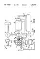
- FIG. 3is a block diagram of the parallel hybrid drive system of the invention.
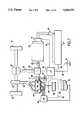
- FIGS. 4-9are schematic diagrams of the hybrid drive system according to the invention operating in different modes and showing flow of energy, in the form of stored electrical energy or fossil fuel, and of power, as torque from either the electric motor or the internal combustion engine;
- FIG. 10is a schematic cross-sectional view of a clutch forming a frictional coupling between one input shaft of a torque transfer unit and either the internal combustion engine or the frame of the vehicle;
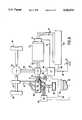
- FIG. 11is a schematic cross-sectional view of the torque transfer unit
- FIG. 12is a schematic circuit diagram of the solid-state switching unit providing AC/DC power conversion, with indication of the control signals provided thereto;
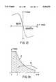
- FIG. 13illustrates the manner of control of the motor as a motor or generator
- FIG. 14illustrates the preferred torque versus speed characteristics of the motor as operated with the corresponding preferred AC/DC power converter, and of the internal combustion engine.
- curve 10represents the output power versus engine speed (RPM) of a typical spark ignition gasoline-fueled internal combustion engine as used with an automatic transmission in a typical sedan of 3,300 pounds. As can be seen, the maximum engine power available is about 165 horsepower at about 5,000 RPM. Also shown in FIG. 1 by curve 12 are the average power requirements of such a vehicle. Points C, S and H on curve 12 show average fuel consumption in city, suburban and highway driving, respectively. Point C on curve 12 shows that the average power required in typical city driving is less than 5 hp. Point S shows that the average power consumed in suburban driving is 10 hp, and point H shows that the power needed for steady-speed highway driving is only about 30 hp. Thus, the vehicle is vastly overpowered at all times except during acceleration or hill-climbing.
- RPMengine speed
- FIG. 1also includes curves indicating the relative fuel consumption of the engine.
- reasonable fuel efficiencythat is, at least about 105 percent relative fuel consumption (100% being ideal)
- FIG. 1thus indicates that the typical internal combustion engine operates with reasonable efficiency only when producing between about 50 and about 90% of its maximum output power.
- the typical automobileonly requires such substantial power under conditions of extreme acceleration or hill climbing.
- the relative fuel consumptionis on the order of 190 percent of that required during the most efficient operation of the engine. The situation is even worse in suburban driving, where the relative fuel consumption is nearly 300 percent of the most efficient value, and in city driving, where the relative fuel consumption is almost 350 percent of that required at most efficient operation.
- FIG. 1thus demonstrates that an internal combustion engine having sufficient horsepower for adequate acceleration and hill climbing capability must be so oversized with respect to the loads encountered during most normal driving that the engine is grossly inefficient in its consumption of fuel. As noted, FIG. 1 further shows that only about 30 horsepower is needed to cruise on the highway even in a relatively large car.
- FIG. 2is similar to FIG. 1, and illustrates the operational characteristics of the same 3,300 pound car if driven by a relatively small engine having a maximum horsepower rating of about 45 horsepower at 4,000 RPM.
- the power requirement of the vehicle during highway cruisingshown by point H on curve 14, is in the center of the most efficient region of operation of the engine.
- this small enginethus optimized for highway cruising, there is a substantial gap between the engine operating power line 16 and the average power requirement line 14. That is, even this small engine produces substantially more power at low RPM than needed for city driving (point C) or for suburban driving (point S). Accordingly, even with a small engine sized appropriately for highway cruising, substantial inefficiencies at lower speeds persist. Moreover, of course, such a vehicle would have unsatisfactory acceleration and hill climbing ability. Therefore, the answer is not simply to replace large internal combustion engines with smaller internal combustion engines.
- straight electric vehiclesthat is, vehicles having electric traction motors and batteries requiring recharge at the end of each day's use, do not have sufficient range and require too much time to recharge to fully replace conventional automobiles. Further, the operational costs of such vehicles are not competitive with internal combustion vehicles operated on fuels derived from renewable resources such as ethanol, and are even less competitive with gasoline-fueled automobiles.
- a first type of series hybrid vehiclesinvolving a gasoline engine driving a generator charging a battery powering an electric traction motor, are limited in acceleration and hill climbing ability unless the electric motor is made very large, costly, and bulky.
- the alternative series hybrid approachinvolving a transmission between a relatively smaller electric motor and the wheels to provide the torque needed to accelerate quickly, loses the virtue of simplicity obtained by elimination of a multi-speed transmission.
- These vehiclesfail to realize the advantages provided by the parallel hybrid system in which both an internal combustion engine and an electric motor provide torque to the wheels as appropriate.
- the prior art relating to parallel hybrid vehiclesfails to disclose a system sufficiently simple for economical manufacture.
- the artfurther has failed to teach the optimum method of operation of a parallel hybrid vehicle.
- the internal combustion engine of a hybrid vehicleis sized to supply adequate power for highway cruising, preferably with some additional power in reserve, so that the internal combustion engine operates only in its most efficient operating range.
- the electric motorwhich is substantially equally efficient at all operating speeds, is used to supply additional power as needed for acceleration and hill climbing, and is used to supply all power at low speeds, where the internal combustion engine is particularly inefficient, e.g., in traffic.
- FIG. 3shows a block diagram of the drive system of the vehicle according to the invention.
- Internal combustion engine 40is connected by way of a two-way clutch 50 to a controllable torque transfer unit 28.
- the torque transfer unit 28receives torque from engine 40 and/or from alternating current electric motor 20 and transmits this torque to the drive wheels 34 of the vehicle by way of a conventional differential 32.
- the motor 20receives power from a bi-directional AC/DC power converter 44 comprising a solid-state switching network connected in turn to a battery 22.
- the battery 22is charged by power generated by the motor 20 when operated as a generator, that is, when driven by the engine 40 by way of the controllable torque transfer unit 28, or in a regenerative braking mode.
- a microprocessor controller 48controls the rate of supply of fuel to engine 40 as indicated at 56, controls the opening of a throttle 61 by which the engine 40 receives intake air from the atmosphere for combusting the fuel, controls the operation of the two-way clutch 50, controls the operation of the torque transfer unit 28, and controls bi-directional flow of power between the battery 22 and the motor 20 through frequency, current, and polarity signals passed to the bi-directional AC/DC power converter 44.
- the microprocessor 48receives control inputs from the vehicle operator, namely acceleration, reverse, and deceleration or braking commands, and receives data from sensors monitoring various elements of the system, including data responsive at least to engine speed, motor speed, battery voltage, battery charging status, and ambient temperature input. Other input data may be provided as required.
- the microprocessoralso controls operation of the power converter 44 by way of frequency, current and polarity signals.
- both the engine 40 and the motor 20provide torque to the drive wheels 34 by way of the controllable torque transfer unit 28.
- the microprocessor 48controls the flow of torque between the motor 20, the engine 40, and the wheels 34 responsive to the mode of operation of the vehicle. For example, when the vehicle is cruising along the highway, all torque is preferably supplied from the engine 40. However, when the vehicle starts down a hill, and the operator lifts his foot from the accelerator pedal, the kinetic energy of the vehicle and the engine's excess torque may be used to drive the motor 20 as a generator so as to charge the batteries. If the vehicle then starts to climb a hill, the motor 20 is used to supplement the output torque of engine 40.
- the motor 20can be used to start the engine 40, e.g., when accelerating in traffic or the like.
- the various modes of operation of the systemwill be described below in connection with FIGS. 4-9, after which further details of the various elements of the system are provided.
- FIGS. 4-9are schematic illustrations of the operation of the parallel hybrid vehicle of the invention overcoming the deficiencies of the prior art, each depicting operation of the vehicle under various circumstances.
- flow of potential energy--either electrical energy, or combustible fuel--is shown in dot-dash lines, while flow of mechanical energy, that is, torque, is shown by dashed lines.
- FIG. 4illustrates operation in low speed circumstances, e.g., in city traffic or reversing.
- the parallel hybrid vehicle drive systemincludes an electric motor 20 powered by energy stored in a relatively large, high voltage battery pack 22. Energy flows from battery 22 to motor 20 as indicated by a dot-dash line shown at 24.
- the electric motor 20provides torque, shown as a dashed line 25, transmitted from the motor output shaft 26 through a torque transfer unit 28 and a drive shaft 30 to a conventional differential 32 and then to wheels 34 of the vehicle.
- FIG. 4indicates that the flow of energy in heavy traffic or for reversing is simply from battery 22 to electric motor 20; torque flows from the motor 20 to the wheels 34.
- electric motor 20provides all of the torque needed to move the vehicle.
- Other combinations of torque and energy flow required under other circumstancesare detailed below in connection with FIGS. 5-9. For example, if the operator continues to command acceleration, an acceleration/hill climbing mode illustrated in FIG. 6 may be entered, followed by a highway cruising mode illustrated in FIG. 5.
- battery 22is a series-connected battery pack made up of conventional lead acid batteries, or, preferably, bipolar electrode lead acid batteries.
- Battery 22is capable of delivering between about 30 and about 50 amperes, and possibly up to 75 amperes.
- the voltage of the battery packvaries with the weight of the vehicle. For example, the preferred maximum working parameters for a typical 3,300 pound vehicle are about 1200 volts at about 50 amperes.
- Lighter vehicles according to the inventionare preferably operated at lower voltages and similar currents, for reasons of manufacturing convenience and to allow reduction in the number of batteries required. Limiting the current to no greater than 50 amperes allows relatively inexpensive and readily assembled plug-in connectors to be used in lieu of bolted connections required where higher currents are involved, and allows some of the circuitry to be provided in printed circuit form, for manufacturing economy and convenience.
- a typical battery pack for a 3,300 pound vehiclewill comprise 400-500 pounds of conventional lead-acid batteries.
- the battery packwill discharge by 40% in 3 minutes in driving the 3,300 pound vehicle up an 8% grade at 62 mph, assisted by a 45 hp engine. This represents entirely adequate performance on a very steep climb. Similar performance can be expected from a 200-250 pound bipolar electrode lead-acid battery pack.
- High energy capacitorsmay also be employed for energy storage in the system of the invention.
- a solid-state switching AC/DC power converter unit 44preferably comprising six MOS controlled thyristors (MCTs) (see FIGS. 12 and 13) operated responsive to control signals provided along line 46 by microprocessor 48 to convert DC current provided by battery 22 to AC current of appropriate frequency, wave shape and amplitude to operate AC induction motor 20.
- MCTsMOS controlled thyristors
- Such MCTsare solid state switching devices rated at, for example, 2500 volts at 100 amperes; other solid state switching elements having similar capabilities may be employed as suitable.
- Switching unit 44also rectifies AC generated by motor 20 when operated as a regenerative brake or generator to charge battery 22 with rectified DC.
- the output torque from motor 20is transmitted by way of torque transfer unit 28 through a conventional differential 32 to the vehicle drive wheels 34, which may be the front or the rear wheels of the vehicle, or all four wheels.
- An exemplary embodiment of the controllable torque transfer unit 28is detailed in FIG. 11.
- a clutch 50may be provided between engine 40 and torque transfer unit 28, as discussed in connection with FIG. 3.
- controllable torque transfer unit 28is controlled by microprocessor 48 to direct flow of torque between motor 20, engine 40, and wheels 34, as required in each operational mode of the vehicle. For example, in the power flow diagram of FIG. 4, showing operation in a heavy traffic/reversing mode, power is transmitted directly from output shaft 26 of motor 20 to drive shaft 30.
- the engine 40may be any of a number of types, including two or four stroke, Wankel-cycle, turbine, or more exotic types. Chemical energy is supplied to engine 40 in the form of combustible fuel 36, which may be gasoline, diesel fuel, methanol, ethanol, natural gas, propane, mixtures thereof, or other fuels. To allow engine 40 to be connected to wheels 34 without a variable-speed transmission while being operable over a wide range of road speeds, engine and engine 40 has a relatively "flat" output torque versus RPM characteristic--that is, engine 40 produces substantial torque over a wide RPM operating range. See FIG. 14.
- the engine 40will be operated in lean burn mode (that is, air will be supplied slightly in excess of the amount required for stoichiometric combustion) to achieve complete combustion.
- the enginewill be operated at a lower temperature and thus at slightly reduced thermodynamic efficiency (e.g., 2-3% lower) than is a conventional engine. Only 2 or 3 cylinders will be used in this engine to maintain a high volume-to-surface area ratio within its cylinders, in order to further reduce toxic emissions. That is, because the cylinder walls of any internal combustion engine are cool in comparison with the rest of the combustion chamber, the fuel does not burn as completely along the cylinder walls as elsewhere. Therefore, because an engine of given displacement having fewer cylinders will have a higher ratio of cylinder volume to cylinder surface area, it will emit proportionately lesser quantities of unburned hydrocarbons than one having more cylinders.
- engine 40be a gasoline-fueled, spark-ignition, water-cooled three-cylinder four-stroke overhead cam unit of between about 750 cc and one liter capacity producing between forty and sixty peak horsepower at on the order of 6000 RPM.
- Such an enginecan be manufactured using conventional technology, and may be fuel injected or carbureted.
- EFIelectronic fuel injection
- the ignition of internal combustion engine 40may be controlled by an electronic engine management system (EEM) 55 controlled by or integrated with microprocessor 48.
- EEMelectronic engine management system
- the internal combustion engine 40receives intake air via an air filter 60; the microprocessor 48 may control the amount of air admitted by way of throttle 61, or may measure the amount of air admitted, as in certain conventional EFI systems.
- Internal combustion engine 40exhausts burnt gases via a tail pipe 62 and muffler 64.
- microprocessor 48In addition to controlling the generation of appropriate AC drive pulses via control signals provided to switching unit 44, and controlling electronic engine management system 55 and electronic fuel injection 56, microprocessor 48 also monitors the level of charge of batteries 22 via a line 66 and responds to operator commands received over a control line 68 from operator control input devices, shown schematically as a pedal 70. Thus, as discussed in connection with FIG. 3, microprocessor 48 is provided with all information relevant to the performance of the system, and appropriately controls torque transfer unit 28, internal combustion engine 40, switching unit 28, and electric motor 20 to ensure that appropriate torque is delivered to the wheels 34 of the vehicle.
- Control of switching unit 44 to appropriately operate motor 20is within the present skill of the art.
- numerically controlled machine toolsemploy microprocessor-controlled synchronous AC motors to provide very precise rotational speeds for accurate control of complex motions.
- Such precise motor controlis not required for practice of the present invention, nor is a synchronous motor required.
- the driver's inputis an integral element of the system, the driver can make any fine adjustments required simply by varying the pressure exerted on the control input devices 70. Thus, the operator becomes an active feedback element in the control system.
- the operator input devices 70may include accelerator and brake pedals, directional control switches, and the like. Pressure on the accelerator pedal indicates to the microprocessor that more power is required; pressure on the brake causes the microprocessor to initiate regenerative braking, as discussed below.
- the operatormay also be provided with additional input controls, for example, to prevent the microprocessor from shutting off internal combustion engine 40 during braking when the operator anticipates a need for full power.
- a multipole AC induction motor 20is preferred over a DC motor due to the well known preferable torque versus speed characteristics of AC induction motors in combination with an appropriate power converter. While both AC and DC motors produce their maximum torque at zero RPM, essential in starting a heavy load from rest without a clutch, the output torque from a DC motor drops linearly with RPM. As shown by curve A of FIG. 14, a multipole AC induction motor provided with drive pulses of the proper type (readily provided by microprocessor 48 controlling switching unit 44) provides constant output torque up to a particular RPM level, e.g., point C in FIG. 14, then hyperbolically decreasing torque while providing constant output power. This torque characteristic is ideal for vehicle propulsion, particularly at low speeds.
- point Cmay correspond to a 120 Hz frequency of the AC voltage signal provided by switching unit 44 (see FIGS. 12 and 13) with maximum motor RPM reached at an AC frequency of up to 1000 Hz; more preferably, point C corresponds to a minimum 150 Hz AC frequency, and maximum motor RPM to a maximum AC frequency of 600 Hz.
- the desired constant-torque characteristics of the output of motor 20are provided below point C by appropriately shaping the AC drive pulses in known manner.
- An AC induction motorcan readily be operated in reverse, that is, as a generator, simply by controlling the sequence of connection of the phase windings across the DC battery connection. See FIGS. 12-13.
- the torque output by engine 40is substantially constant over its useful working RPM range, as shown by curve B of FIG. 14. Engine 40 thus provides adequate torque for highway cruising over a wide range of vehicle speeds without the necessity of a multi-speed transmission.
- FIGS. 5-9show operation of the system in other modes.
- FIG. 5depicts operation of the system in a highway cruising mode wherein, as indicated above, all torque required to drive the vehicle at normal highway speeds (e.g. above about 45 mph) is provided by the internal combustion engine 40 supplied with combustible fuel 36 via EFI unit 56.
- energy flow as indicated by the dot-dash lineis from the tank 38 through EFI unit 56 into engine 40, while torque flows from engine 40 through torque transfer unit 28, to axle differential 32 and thence to road wheels 34.
- the engine 40is coupled to the wheels at a fixed ratio, that is, there is no variable-ratio transmission.
- the output torque of internal combustion engine 40may be directly variable responsive to the operator's control inputs.
- Microprocessor 48monitors the operator's inputs and the vehicle's performance, and activates electric motor 20 when torque in excess of the capabilities of engine 40 is required. Conversely, if excess engine torque is available (see the discussion of FIG. 7 below) it can be transformed into electrical energy in motor 20 and stored by battery 22.
- FIG. 6illustrates operation of the system in a high-speed acceleration and/or hill climbing mode, wherein both internal combustion engine 40 and electric motor 20 provide torque to road wheels 34.
- electrical energyas shown by the dot-dash line, flows from battery 22 to motor 20; additionally, gasoline or another combustible fuel flows from tank 38 to EFI unit 56 so that both internal combustion engine 40 and electric motor 20 can supply torque indicated by the dashed lines to road wheels 34.
- microprocessor 48controls operation of both motor 20 and internal combustion engine 40 through switching unit 44 and EFI unit 56, respectively.
- Low-speed acceleration--up to about 25 mph--is powered by the motor 20 alone.
- FIG. 7depicts operation of the system in a regenerative braking or coasting mode, wherein electrical energy is generated by motor 20, rectified in switching unit 44 and fed back to charge batteries 22, as indicated by the position of the arrow head on the dot-dash line connecting switching unit 44 to batteries 22.
- the regenerative braking/coasting modecan be entered whenever the driver removes his foot from an accelerator pedal and depresses a brake pedal, both indicated schematically at 70, or on downhill stretches.
- the kinetic energy of the vehicleis fed back from road wheels 34 and differential 32 via drive shaft 30 to torque transfer unit 28 to electric motor 20; microprocessor 48 controls appropriate operation of switching unit 44 (see FIGS. 12 and 13) to generate rectified DC for storage in battery 22 from AC provided by motor 20.
- FIG. 8illustrates operation of the system during starting, that is, when electric motor 20 starts internal combustion engine 40 from rest.
- energyflows from battery 22 to switching unit 44, and output torque is supplied by output shaft 26 of motor 20.
- internal combustion engine 40will typically be started when the vehicle is already under power, e.g., in heavy traffic that requires occasional acceleration, motor 20 simultaneously supplies torque to internal combustion engine 40 for starting it and also to driveshaft 30 to propel the vehicle forward.
- microprocessor 48controls throttle 61, EFI unit 56 and EEM unit 55 ensures quick, smooth starting. When engine 40 has started, microprocessor 48 shifts vehicle operation to the mode of FIG. 6.
- FIG. 9illustrates system operation in the battery charging mode.
- Battery chargingtakes place automatically, under microprocessor control, responsive to monitoring the state of charge of battery 22 via control signal line 66.
- Internal combustion engine 40charges battery 22 by rotating motor 20, providing AC rectified by switching unit 44 to DC suitable for charging battery 22. If this mode is entered during driving, internal combustion engine 40 also supplies torque to road wheels 34, as indicated by the dashed lines.
- FIGS. 10 and 11show respectively a two-way clutch 50 employed to couple the internal combustion engine 40 to the drive train of the vehicle, and the controllable torque transfer unit 28. It will be appreciated that the disclosed embodiments of these and other elements of the vehicle of the invention are exemplary only, and that other devices performing equivalent functions are known to the art and are considered to be within the scope of the invention.
- the two-way clutch 50 shown in FIG. 10receives torque from an engine flywheel 82 fixed to the engine output shaft 41, and includes a double-sided friction disk 84 splined onto an input shaft 86 of the controllable torque transfer unit 28.
- a throwout mechanism 88 controlled by microprocessor 48controls engagement of the friction disk 84 with either the flywheel 82 or a stationary plate 90 fixed with respect to the vehicle. Therefore, depending upon the position of the friction disk 84, torque may be transmitted from engine shaft 41 to input shaft 86, or input shaft 86 can be fixed with respect to the vehicle, for reasons made clear below.
- FIG. 11shows one embodiment of the controllable torque transfer unit 28.
- the controllable torque transfer unit 28comprises four constantly-meshing bevel gears 94, 96, 98 and 100.
- a first bevel gear 94is fixed to the input shaft 86 for receiving torque from the engine 40 via clutch 50 (FIG. 10).
- the second bevel gear 96is fixed to the motor shaft 26 for receiving torque from the electric motor 20.
- Bevel gears 94 and 96are journaled for free rotation about an axis of housing 92.
- gears 98 and 100are journaled for rotation in bores in housing 92, and have their axes lying in a plane perpendicular to the axis of housing 92.
- Locking devices indicated schematically at 106are provided for control of the rotation of gears 98 and 100 with respect to housing 92.
- gears 98 and 100may be locked with respect to housing 92, or may rotate freely with respect to housing 92.
- locking devices 106are further controllable to provide substantial torque transfer between gears 98 and 100 and housing 92. Accordingly, rotation of gears 98 and 100 may take place in a "limited-slip" manner, discussed below.
- the operation of locking devices 106 and accordingly the rotation of gears 98 and 100 with respect to the housing 92is controlled by microprocessor 48.
- clutch 50can be operated to decouple input shaft 86 from engine output shaft 41 and lock input shaft 86 to stationary disk 90. In this circumstance, with gears 98 and 100 fixed with respect to housing 92, torque is transmitted directly from input shaft 26 to driveshaft 30.
- the torque transfer unitWhen gears 98 and 100 are free to rotate within housing 92, the torque transfer unit is said to be operated in a "differential" mode. In this mode, torque from engine 40 may be transferred, for example, to motor 20 operated as a generator to charge battery 22, and also to driveshaft 30, to propel the vehicle forward. More specifically, in the differential mode, if the engine and motor shafts rotate in opposite directions at the same speed, the housing 92 will be stationary. If the speeds of input shafts 86 and 26 differ, torque transferred to housing 92 by spur gears 98 and 100 will cause the housing 92 to rotate at a differential speed.
- gears 94, 96, 98 and 100have equal numbers of teeth, the differential speed at which housing 92 rotates is equal to the difference in speeds of shafts 94 and 96. Equal amounts of torque are transmitted by each shaft, while the flow of power is proportional to the speeds of the corresponding shafts.
- housing 92rotates at the speed of the engine shaft and/or the motor shaft, depending on the operation of clutch 50.
- the torque transmitted by the housing 92 to pinion 102is the sum of the torques provided by motor 20 and engine 40 to input shafts 26 and 86 respectively.
- pinions 98 and 100may be locked to housing 92 by locking devices shown schematically at 106.
- Devices 106may comprise magnetic or friction clutches for controllably locking gears 98 and 100 to housing 92.
- Devices 106are operated by microprocessor 48 so that microprocessor 48 can control the torque transfer unit 28 in accordance with the selected operational mode of the vehicle of the invention.
- locking devices 106may provide a fixed or variable amount of slip between gears 98 and 100 and housing 92, whereupon torque transfer unit 28 is said to be operated in a "limited-slip" or “limited-slip differential” mode. In this mode of operation, while gears 98 and 100 rotate with respect to housing 92, their rotation is not free. For example, a fraction of the torque imparted to gears 98 and 100 from input shaft 41 may be transferred to housing 92 by frictional engagement (for example) of locking devices 106. This fraction of the total torque drives the vehicle forward; the remainder is transferred to motor 20 and is employed to charge the battery.
- the rotational speed of housing 92is not an algebraic sum of the speeds of shafts 26 and 86 (as in the cases of the parallel and differential modes of operation of torque transfer unit 28), but is controlled responsive to the amount of slip provided by locking devices 106.
- the amount of slipmay be controlled by the microprocessor, or may be fixed.
- the engine output poweris divided in order to propel the vehicle forward and to charge the batteries.
- Locking devices 106allow differential operation of the gears within the housing 92 and therefore allow the power output by the engine to be divided as determined to be appropriate by microprocessor 48.
- the load provided by the motor to the enginecan be controlled.
- the microprocessor 48may determine the load (if any) to be provided to the engine by the motor, responsive to the load imposed by the vehicle's propulsion requirements, so that the engine 40 can be operated in its most fuel efficient operating range.
- the present hybrid electric vehicledoes not employ a multi-speed transmission. Accordingly, the ratios of the rates of rotation of the engine 40 and motor 20 to those of the respective input shafts of torque transfer unit 28, and the ratio of the rates of rotation of the housing 92 and of the wheels 34, are fixed. However, it is within the scope of the invention to employ constant-ratio reduction gears, for example, between motor 20 or engine 40 and torque transfer unit 28.
- the ratio of the rate of rotation of housing 92 to the difference between the rates of rotation of the input shaftsis fixed; in the limited-slip differential mode of operation, this latter ratio may alternatively be controlled to assume a second fixed value, or may be variable under microprocessor control.
- the microprocessor 48disconnects the engine 40 from the drive and shuts it off. Under these circumstances only the motor 20 provides power to drive the vehicle. If the brake pedal is depressed by the driver, the microprocessor 48 causes the motor frequency to advance, so that motor 20 performs as a generator to recover some of the braking energy back into the battery. See FIGS. 12-13. Up to 40-50% on average of the vehicle's kinetic energy may thus be recovered and stored in battery 22. Excess braking energy is still dissipated by the brake pads of the vehicle.
- the microprocessor 48actuates the two-way clutch 50 (see FIG. 10) to connect the engine 40 to the torque transfer unit. Then the motor 20 will start the engine 40 while driving the vehicle, with the microprocessor 48 providing optimal starting conditions as above. Locking devices 106 are released, such that the torque transfer unit 28 operates in differential mode.
- the microprocessor 48controls the speeds of both the engine 40 and the motor 20 such that the difference in speed of their output shafts is equal to the speed required by the driver for vehicle propulsion. As noted, engine speed is controlled such that engine 40 provides 60-90% of its maximum power over a wide range of vehicle speeds. Excess power is used to recharge the battery 22.
- the microprocessor 48controls the switching network 44 so that the motor 20 acts as a generator to charge the battery. See FIGS. 12-13.
- the microprocessor 48monitors the state of battery charge and terminates this mode of driving when the battery is fully recharged.
- microprocessor 48monitors the state of charge of batteries 22 via line 66 and recharges the batteries whenever the charge is depleted by more than about 10-20%.
- Such frequent light chargesresult in improved battery life as compared to regularly allowing the batteries to be nearly fully discharged, followed by a lengthy recharge period, as is necessary in operation of entirely electric vehicles.
- the duty cycle of the internal combustion engine for battery chargingis 10-20%; that is, in traffic, internal combustion engine 40 charges the battery perhaps once per hour for a period of approximately twelve minutes.
- the engine 40it is within the scope of the invention to operate the engine 40 outside its most fuel efficient operating range, on occasion. For example, if the torque transfer unit does not provide a limited-slip mode of operation the combined load of low-speed vehicle operation in traffic together with battery charging may be less then the minimum power produced by the engine in its most efficient operating range. In these circumstances, it is preferable to use the engine somewhat inefficiently rather than to discharge the batteries excessively, which would substantially reduce the battery lifetime.
- the speed of the vehicle on averageis between 30-45 mph.
- the vehiclewill operate in a highway mode with the engine running constantly after the vehicle reaches a speed of 30-35 mph.
- the enginewill continue to run unless the engine speed is reduced to 20-25 mph for a period of time, typically 2-3 minutes. This speed-responsive hysteresis in mode switching will eliminate nuisance engine starts.
- FIG. 12shows one circuit for the solid-state switching AC/DC converter/motor controller unit 44.
- switching controller unit 44the principal functions of switching controller unit 44 are to convert DC provided by batteries 22 into appropriate AC pulses for operation of motor 20, and similarly to convert AC provided by motor 20 where operated as a generator to DC for charging battery 22.
- the circuit illustrated in FIG. 12 for carrying out these functionsis a three-phase bridge circuit comprising six solid-state devices 110 operated as switches responsive to control signals A-F. Switching devices 110 are in parallel with six flyback diodes 112.
- motor 20comprises three phase windings which are connected to the lines marked Phases X, Y and Z. Positive and negative bus lines 116 and 118 marked + and - are connected to the battery 22.
- the motor phasesare connected to the bus lines 116 and 118 by solid-state switches 110 at appropriate times by signals A-F.
- signals A-Fare provided by a controller 114 responsive to desired frequency, polarity and pulse width or output current signals provided by microprocessor 48.
- the frequency commandestablishes the synchronous speed of the motor
- the polarity commandestablishes the direction of rotation
- the pulse width or current commandestablishes the output torque within the torque envelope shown by curve A of FIG. 14.
- controller 114could also be configured as part of microprocessor 48 if convenient.
- Switches 110are thus controlled responsive to the desired frequency, polarity, and current signals to connect the various phase windings of AC induction motor 20 to operate as a motor or generator.
- FIG. 13indicates that the operation of motor 20 as a motor or a generator is a function of the "slip" or "space phase” angle.
- the slip angleis the ratio of the difference between the loaded shaft speed and a desired synchronous speed to that synchronous speed.
- the slip angleis zero.
- the slip anglebecomes negative and the motor generates torque, that is, acts as a power source. If the AC frequency is changed, the synchronous speed will change accordingly. If this frequency change is such that the slip angle becomes positive, the motor will produce negative torque, i.e., will act as a generator and will become a load. Therefore, by appropriately altering the AC frequency, power is generated, charging the battery.
- the electrical circuits connecting the battery and the motor via the controllershould operate at low current and relatively high voltage.
- the currentshould be less than 75 amperes and is preferably in the 30-50 ampere range; in the example given above of a 60-80 horsepower motor operating at 50 amperes maximum current to power a 3,300 pound vehicle, the DC voltage will be 1,000 to 1,400 volts. Typical maximum voltages corresponding to light and heavy vehicles are between 500 and 1,500 volts.
- the battery capacitymay also be varied in accordance with the intended use of the vehicle; for example, vehicles sold for intended use in flat terrain will normally require less battery capacity than those for use in mountainous terrain.
- FIGS. 1 and 2indicate that an internal combustion engine 40 of about forty-five horsepower will be adequate to provide sufficient power for cruising in a 3,300 pound automobile at steady speed on the highway. The next criterion is to provide enough power for adequate acceleration and hill climbing; an electric motor 20 of about sixty-five horsepower is appropriate, so that a total of one hundred ten horsepower is available. It will be recognized of course that these figures are subject to considerable variation. However, it is considered an aspect of the invention that the maximum power of the electric motor is at least about equal and possibly up to double the maximum power of the internal combustion engine; this ratio reflects approximately the ratio of the power required for cruising and for acceleration or hill climbing.
- electric motor 20is an asynchronous AC induction motor driven by pulses provided by MOS controlled thyristors switched by microprocessor 48, or by a dedicated motor controller responsive to microprocessor 48.
- motor 20operates on relatively high voltage and relatively low current AC of at least about 120 Hz and up to 1000 Hz phase voltage frequency. All else being equal, such a high frequency motor can be made more compact than the typical lower frequency 60 Hz AC motor. However, higher frequencies involve increased power losses.
- a multipole motorone having at least ten poles
- an 18-pole motor 20 operating at 150-600 Hzwill have a maximum speed of 4,000 rpm; this would be conveniently close to the operating speed of engine 40, so that reduction gearing need not be provided.
- the advantage of operating at relatively low maximum currents of between 30 and 75 amperes and preferably no more than 50 amperesis that by thus lowering the current as compared to the high currents of prior hybrid and electric vehicles, electrical connection and circuit manufacturing technologies can be employed that will simplify the manufacture of the vehicle and render its operation most efficient.
- the maximum voltageis then chosen in accordance with the vehicle weight. More specifically, conductors carrying up to about 50 amperes can be connected through simple plug-in connectors as commonly used in electrical power wiring; higher currents, as taught by the prior art relating to hybrid vehicles, require bolted connections. Moreover, for a given power transmission requirement, higher voltages and lower currents result in reduced resistance heating losses as compared to lower voltages and higher currents.
- switching module 44carries the switching elements 110 on a ring-shaped printed circuit board disposed around shaft 26 of motor 20, the elements 110 being cooled by heat sinks in the flow path of a fan mounted on shaft 26 to ensure adequate cooling. If it is desired to manufacture a smaller, lighter vehicle according to the invention, the same circuit components could be used and the voltage simply reduced by reducing the number of individual batteries making up battery pack 22, providing substantial manufacturing economy.
- the internal combustion engineis run only in the near vicinity of its most efficient operational point, that is, such that it produces 60-90% of its maximum torque whenever operated. This in itself will yield improvement in fuel economy on the order of 200-300%. More specifically, a 200-300% reduction in fuel consumption will provide an equal reduction in carbon dioxide emissions, as the amount of carbon dioxide emitted is proportional to the amount of fuel used. If ethanol is used as a fuel, that is, if the fuel is derived from renewable plant life rather than fossil fuel, an overall reduction in global carbon dioxide emissions will be achieved since the plants consume carbon dioxide during growth.
- Toxic pollutantssuch as nitrogen oxides, carbon monoxide and hydrocarbons will be reduced by 200-300% simply through use of less fuel. As indicated above, a further reduction can be obtained by operating the engine in a lean burn mode. Although reduction of the combustion temperature in order to reduce the amount of nitrogen oxides emitted also reduces the thermodynamic efficiency, this technique can still be usefully employed; the improvement in fuel efficiency realized according to the invention is so high that a slight reduction in thermodynamic efficiency resulting in the reduction of the amount of nitrogen oxides emitted can be tolerated without substantial loss in overall economy.
- the following parametersare relevant to the performance of a parallel hybrid vehicle: 1) the total maximum power available to drive the vehicle; 2) the ratio of the maximum output power of the internal combustion engine versus that of the electric motor; 3) the energy capacity of the battery; 4) the function of the power converter used to convert mechanical energy to electrical energy for storage and vice versa; 5) the availability of power to recharge the battery at any time; 6) the optimization of the control algorithm; and 7) appropriate mechanical linkage between the engine, the motor, and the drive wheels.
- these parametersare optimized so as to ensure that the engine is operated at all times at its maximum point of efficiency, and such that the driver need not consider the power source being employed at any given time.
- the cost of the engine according to the inventionis 30-50% that of a conventional engine.
- the cost of the clutch and torque transfer unitis no more than 33% of the cost of a conventional automatic transmission. No alternator or starter is required.
- the cost of the motor, the solid state switching unit, and the increased battery capacityis roughly equivalent to the cost of the components eliminated according to the invention. Weight and manufacturing complexity are likewise comparable.
- a hybrid electric vehicleis provided that is fully competitive with conventional internal combustion engine driven vehicles in terms of acceleration, cost, weight, and manufacturing and operational convenience, while obtaining very substantial improvements in fuel efficiency and even more substantial reduction in emission of pollutants.
Landscapes
- Engineering & Computer Science (AREA)
- Chemical & Material Sciences (AREA)
- Combustion & Propulsion (AREA)
- Transportation (AREA)
- Mechanical Engineering (AREA)
- Power Engineering (AREA)
- Automation & Control Theory (AREA)
- Electric Propulsion And Braking For Vehicles (AREA)
Abstract
Description
Claims (40)
Priority Applications (2)
| Application Number | Priority Date | Filing Date | Title |
|---|---|---|---|
| US07/947,691US5343970A (en) | 1992-09-21 | 1992-09-21 | Hybrid electric vehicle |
| PCT/US1994/007294WO1996001193A1 (en) | 1992-09-21 | 1994-07-01 | Hybrid vehicle |
Applications Claiming Priority (2)
| Application Number | Priority Date | Filing Date | Title |
|---|---|---|---|
| US07/947,691US5343970A (en) | 1992-09-21 | 1992-09-21 | Hybrid electric vehicle |
| PCT/US1994/007294WO1996001193A1 (en) | 1992-09-21 | 1994-07-01 | Hybrid vehicle |
Publications (1)
| Publication Number | Publication Date |
|---|---|
| US5343970Atrue US5343970A (en) | 1994-09-06 |
Family
ID=26788314
Family Applications (1)
| Application Number | Title | Priority Date | Filing Date |
|---|---|---|---|
| US07/947,691Expired - LifetimeUS5343970A (en) | 1992-09-21 | 1992-09-21 | Hybrid electric vehicle |
Country Status (2)
| Country | Link |
|---|---|
| US (1) | US5343970A (en) |
| WO (1) | WO1996001193A1 (en) |
Cited By (417)
| Publication number | Priority date | Publication date | Assignee | Title |
|---|---|---|---|---|
| US5427196A (en)* | 1992-07-08 | 1995-06-27 | Kabushikikaisha Equos Research | Electric motor drive system |
| US5513719A (en)* | 1993-05-24 | 1996-05-07 | Kabushikikaisha Equos Research | Hybrid vehicle |
| EP0727332A1 (en)* | 1995-02-15 | 1996-08-21 | FICHTEL & SACHS AG | Parallel hybrid propulsion system for a motor car |
| US5558595A (en)* | 1995-02-17 | 1996-09-24 | General Motors Corporation | One-mode, input-split, parallel, hybrid transmission |
| US5562565A (en)* | 1992-11-27 | 1996-10-08 | Kabushikikaisha Equos Research | Power transmission system in a hybrid vehicle |
| US5568023A (en)* | 1994-05-18 | 1996-10-22 | Grayer; William | Electric power train control |
| DE19528628A1 (en)* | 1995-08-04 | 1997-02-06 | Audi Ag | Hybrid drive for IC engine vehicle - has electric motor also used as generator during regenerative braking, with efficiency dependent on deceleration and gear ratio |
| US5621304A (en)* | 1994-08-22 | 1997-04-15 | Honda Giken Kogyo Kabushiki Kaisha | Electric generation control system for hybrid vehicle |
| WO1997018101A1 (en)* | 1995-11-14 | 1997-05-22 | Toyota Jidosha Kabushiki Kaisha | Power output apparatus, method of controlling power output apparatus, and driving system with power output apparatus incorporated therein |
| US5644200A (en)* | 1994-10-03 | 1997-07-01 | Yang; Tai-Her | Driving electrical machine speed controlled power combined system and device |
| EP0781680A3 (en)* | 1995-12-27 | 1997-07-23 | Denso Corporation | Power source control apparatus for hybrid vehicles |
| US5656921A (en)* | 1994-05-24 | 1997-08-12 | Rover Group Limited | Control of a vehicle powertrain |
| US5697466A (en)* | 1992-11-12 | 1997-12-16 | Kabushikikaisha Equos Research | Hybrid vehicle |
| US5713814A (en)* | 1995-08-02 | 1998-02-03 | Aisin Aw Co., Ltd. | Control system for vehicular drive unit |
| US5713425A (en)* | 1996-01-16 | 1998-02-03 | Ford Global Technologies, Inc. | Parallel hybrid powertrain for an automotive vehicle |
| EP0826544A1 (en)* | 1996-09-03 | 1998-03-04 | Tai Her Yang | Combined driving system comprising electrical machine and internal combustion engine |
| US5730675A (en)* | 1994-11-04 | 1998-03-24 | Kabushikikaisha Equos Research | Transmission for vehicle |
| US5731643A (en)* | 1996-05-02 | 1998-03-24 | Chrysler Coporation | Stator cooling assembly |
| EP0822114A3 (en)* | 1996-08-02 | 1998-04-08 | Honda Giken Kogyo Kabushiki Kaisha | Control system for hybrid vehicle |
| FR2755406A1 (en)* | 1996-11-07 | 1998-05-07 | Espera | HYBRID MOTOR VEHICLE |
| US5775449A (en)* | 1994-06-06 | 1998-07-07 | Kabushikikaisha Equos Research | Hybrid vehicle |
| US5789882A (en)* | 1995-07-24 | 1998-08-04 | Toyota Jidosha Kabushiki Kaisha | Vehicle control apparatus adapted to select engine-or motor-drive mode based on physical quantity reflecting energy conversion efficiencies in motor-drive mode |
| US5791427A (en)* | 1995-02-03 | 1998-08-11 | Kabushikikaisha Equos Research | Hybrid vehicle |
| US5806617A (en)* | 1995-04-20 | 1998-09-15 | Kabushikikaisha Equos Research | Hybrid vehicle |
| US5820172A (en)* | 1997-02-27 | 1998-10-13 | Ford Global Technologies, Inc. | Method for controlling energy flow in a hybrid electric vehicle |
| WO1998047732A1 (en) | 1997-04-18 | 1998-10-29 | Transport Energy Systems Pty. Ltd. | Hybrid propulsion system for road vehicles |
| US5841201A (en)* | 1996-02-29 | 1998-11-24 | Toyota Jidosha Kabushiki Kaisha | Hybrid vehicle drive system having a drive mode using both engine and electric motor |
| US5839533A (en)* | 1996-04-11 | 1998-11-24 | Toyota Jidosha Kabushiki Kaisha | Apparatus for controlling electric generator of hybrid drive vehicle to control regenerative brake depending upon selected degree of drive source brake application |
| US5842534A (en)* | 1995-05-31 | 1998-12-01 | Frank; Andrew A. | Charge depletion control method and apparatus for hybrid powered vehicles |
| US5845731A (en)* | 1996-07-02 | 1998-12-08 | Chrysler Corporation | Hybrid motor vehicle |
| US5846155A (en)* | 1995-07-19 | 1998-12-08 | Aisin Aw Co., Ltd. | Vehicular drive unit |
| US5865263A (en)* | 1995-02-28 | 1999-02-02 | Kabushikikaisha Equos Research | Hybrid vehicle |
| US5887670A (en)* | 1996-05-16 | 1999-03-30 | Toyota Jidosha Kabushiki Kaisha | Vehicle power transmitting system having devices for electrically and mechanically disconnecting power source and vehicle drive wheel upon selection of neutral state |
| US5890555A (en)* | 1998-01-20 | 1999-04-06 | Miller; George W. | Electric vehicle |
| US5899286A (en)* | 1995-02-02 | 1999-05-04 | Kabushiki Kaisha Equos Research | Hybrid vehicle |
| US5908077A (en)* | 1995-01-30 | 1999-06-01 | Chrysler Corporation | Environmentally sensitive hybrid vehicle |
| US5910722A (en)* | 1997-11-21 | 1999-06-08 | Lockheed Martin Corp. | Hybrid electric vehicle with reduced auxiliary power to batteries during regenerative braking |
| US5934395A (en)* | 1995-10-18 | 1999-08-10 | Toyota Jidosha Kabushiki Kaisha | Hybrid vehicle drive system having two motor/generator units and engine starting means |
| US5941328A (en)* | 1997-11-21 | 1999-08-24 | Lockheed Martin Corporation | Electric vehicle with variable efficiency regenerative braking depending upon battery charge state |
| FR2776969A1 (en)* | 1998-04-07 | 1999-10-08 | Renault | METHOD AND DEVICE FOR CONTROLLING A CHANGE OF REDUCTION RATIO IN A GEARBOX ASSOCIATED WITH AN ELECTRIC MOTOR POWERING A MOTOR VEHICLE |
| US5969624A (en)* | 1995-04-07 | 1999-10-19 | Nippon Soken, Inc, | Battery charge control system for a hybrid vehicle driven by an electric motor and an internal combustion engine |
| US5991683A (en)* | 1997-03-24 | 1999-11-23 | Toyota Jidosha Kabushiki Kaisha | Power output apparatus and method of controlling the same |
| US6003626A (en)* | 1995-10-05 | 1999-12-21 | Toyota Jidosha Kabushiki Kaisha | Hybrid drive system for motor vehicle, having means for inhibiting electricity generating drive mode |
| DE19826677A1 (en)* | 1998-06-16 | 1999-12-23 | Zahnradfabrik Friedrichshafen | Procedure for establishing energy losses in power train, between energy source and driving motor of vehicle during driving operation |
| US6018198A (en)* | 1997-08-29 | 2000-01-25 | Aisin Aw Co., Ltd. | Hybrid drive apparatus for vehicle |
| GB2340463A (en)* | 1998-08-13 | 2000-02-23 | Rover Group | A vehicle with a parallel hybrid powertrain |
| WO2000021770A1 (en) | 1998-10-09 | 2000-04-20 | Panoz Donald E | Control system for parallel hybrid vehicle |
| FR2784626A1 (en)* | 1998-10-16 | 2000-04-21 | Renault | HYBRID DRIVE GROUP |
| US6054776A (en)* | 1997-04-25 | 2000-04-25 | Jatco Corporation | Control apparatus of parallel hybrid electric vehicle |
| US6064161A (en)* | 1997-12-25 | 2000-05-16 | Nissan Motor Co., Ltd. | Vehicle drive device and vehicle drive device control method |
| US6065565A (en)* | 1997-01-30 | 2000-05-23 | Jlg Industries, Inc. | Hybrid power system for a vehicle |
| WO2000015455A3 (en)* | 1998-09-14 | 2000-06-08 | Paice Corp | Hybrid vehicles |
| US6073712A (en)* | 1997-01-23 | 2000-06-13 | Chrysler Corporation | Method of power output level control for a hybrid power train system |
| US6097164A (en)* | 1997-02-04 | 2000-08-01 | Derosa; Glenn P. | On board power regeneration system for electrically operated vehicles |
| US6098733A (en)* | 1995-10-13 | 2000-08-08 | Toyota Jidosha Kabushiki Kaisha | Hybrid drive system for motor vehicle |
| US6098735A (en)* | 1995-09-04 | 2000-08-08 | Abb Ab | Hybrid drive system |
| US6105696A (en)* | 1993-02-06 | 2000-08-22 | Chen; Lei | Electric vehicle with combined motors of multistep power outputs |
| US6114775A (en)* | 1997-10-27 | 2000-09-05 | Mando Machinery Corporation | Control system of auxiliary power system for a hybrid electric vehicle |
| US6116363A (en)* | 1995-05-31 | 2000-09-12 | Frank Transportation Technology, Llc | Fuel consumption control for charge depletion hybrid electric vehicles |
| US6135920A (en)* | 1998-06-19 | 2000-10-24 | Denso Corporation | Apparatus and method for automatically starting and stopping a vehicle engine to effect a smooth change from a vehicle brake release state to a vehicle drive state |
| CN1057880C (en)* | 1996-10-14 | 2000-10-25 | 杨泰和 | Hybrid power system and device controlled by active motor speed |
| US6164400A (en)* | 1998-06-10 | 2000-12-26 | Ford Global Technologies, Inc. | Hybrid powertrain controller |
| US6208034B1 (en)* | 1998-07-13 | 2001-03-27 | Toyota Jidosha Kabushiki Kaisha | Power output device and control method of the power output device and hybrid vehicle driven by the power output device |
| US6209672B1 (en)* | 1998-09-14 | 2001-04-03 | Paice Corporation | Hybrid vehicle |
| US6215283B1 (en)* | 1996-06-14 | 2001-04-10 | Siemens Automotive, S.A. | Method and device for controlling an alternator for a motor vehicle |
| US6223842B1 (en)* | 1998-05-18 | 2001-05-01 | Hitachi, Ltd. | Hybrid vehicle |
| US6230496B1 (en)* | 2000-06-20 | 2001-05-15 | Lockheed Martin Control Systems | Energy management system for hybrid electric vehicles |
| US6237709B1 (en)* | 1995-11-14 | 2001-05-29 | Honda Giken Kogyo Kabushiki Kaisha | Hybrid vehicle |
| US6242889B1 (en)* | 1997-04-09 | 2001-06-05 | Dax Industries, Inc. | Combination battery charger/controller |
| US6275763B1 (en) | 2000-03-24 | 2001-08-14 | Ford Global Technologies, Inc. | Temperature dependent regenerative brake system for electric vehicle |
| DE10025037A1 (en)* | 2000-05-20 | 2001-11-22 | Daimler Chrysler Ag | Controller for hybrid drive vehicle combines general demands for acceleration and braking with special torque demands concerning individual wheels |
| US20010045457A1 (en)* | 1999-04-20 | 2001-11-29 | Terranova Steven N. | Remote banking during fueling |
| US6330925B1 (en)* | 1997-01-31 | 2001-12-18 | Ovonic Battery Company, Inc. | Hybrid electric vehicle incorporating an integrated propulsion system |
| US6338391B1 (en) | 1999-03-01 | 2002-01-15 | Paice Corporation | Hybrid vehicles incorporating turbochargers |
| WO2001081145A3 (en)* | 2000-04-26 | 2002-02-07 | Railpower Technologies Inc | Hybrid battery/gas turbine locomotive |
| US6348771B1 (en) | 1999-03-31 | 2002-02-19 | Suzuki Motor Corporation | Motor drive controller for vehicle |
| US6356042B1 (en)* | 2000-07-05 | 2002-03-12 | Gurinder S. Kahlon | Engine shut off system for a hybrid electric vehicle |
| US6362580B1 (en)* | 1999-03-10 | 2002-03-26 | Suzuki Motor Corporation | Controller of vehicle propulsion system |
| US6362602B1 (en) | 2001-05-03 | 2002-03-26 | Ford Global Technologies, Inc. | Strategy to control battery state of charge based on vehicle velocity |
| US6366059B1 (en)* | 1999-07-30 | 2002-04-02 | Honda Giken Kogyo Kabushiki Kaisha | Control system for hybrid vehicle |
| US6367570B1 (en) | 1997-10-17 | 2002-04-09 | Electromotive Inc. | Hybrid electric vehicle with electric motor providing strategic power assist to load balance internal combustion engine |
| US6373206B1 (en) | 1999-03-31 | 2002-04-16 | Suzuki Motor Corporation | Motor drive control apparatus |
| US6376927B1 (en)* | 2000-01-18 | 2002-04-23 | Saturn Corporation | Hybrid electric drive and control method therefor |
| US6377883B1 (en)* | 1999-04-05 | 2002-04-23 | Honda Giken Kogyo Kabushiki Kaisha | Control apparatus for hybrid vehicle |
| US6396165B1 (en) | 1998-09-25 | 2002-05-28 | Toyota Jidosha Kabushiki Kaisha | Engine start control system |
| US20020070271A1 (en)* | 1999-03-29 | 2002-06-13 | Terranova Steven N. | Cash back during dispenser transaction |
| US6427794B1 (en)* | 2001-09-17 | 2002-08-06 | Ford Global Technologies, Inc. | Adaptive demagnetization compensation for a motor in an electric or partially electric motor vehicle |
| US6442455B1 (en) | 2000-12-21 | 2002-08-27 | Ford Global Technologies, Inc. | Adaptive fuel strategy for a hybrid electric vehicle |
| US6450275B1 (en)* | 2000-11-02 | 2002-09-17 | Ford Motor Company | Power electronics cooling for a hybrid electric vehicle |
| EP1130740A3 (en)* | 2000-03-02 | 2002-10-02 | Hitachi, Ltd. | Hybrid electric vehicle with a permanent magnetic type dynamo-electric machine |
| US6461266B1 (en) | 2001-04-26 | 2002-10-08 | Ervin Weisz | Differential electric engine with variable torque conversion |
| US6462551B1 (en) | 2002-01-18 | 2002-10-08 | Ford Global Technologies, Inc. | Method and system to ensure full functionality of battery pack assembly using thermal imaging |
| US6469402B2 (en) | 2000-04-05 | 2002-10-22 | Suzuki Motor Corporation | Control apparatus for hybrid vehicle |
| US6470983B1 (en)* | 1999-04-27 | 2002-10-29 | Hitachi, Ltd. | Hybrid vehicle |
| US20020165660A1 (en)* | 2001-05-03 | 2002-11-07 | Boggs David Lee | Controlled engine shutdown for a hybrid electric vehicle |
| US20020163198A1 (en)* | 2001-05-03 | 2002-11-07 | Gee Thomas Scott | Fail-safe engine cooling control algorithm for hybrid electric vehicle |
| US6480106B1 (en) | 2000-12-11 | 2002-11-12 | Ford Global Technologies, Inc. | Rate of consumption gauge with variable rate of consumption limits |
| EP1256476A2 (en) | 2001-05-09 | 2002-11-13 | Ford Global Technologies, Inc. | Hybrid electric vehicle energy management |
| EP1260397A2 (en) | 2001-05-24 | 2002-11-27 | Ford Global Technologies, Inc. | A control strategy for a hybrid vehicle while traveling in reverse |
| US6490511B1 (en) | 2000-11-10 | 2002-12-03 | Ford Motor Company | Torque-based monitor in a hybrid electric vehicle |
| US6488609B1 (en) | 1999-09-30 | 2002-12-03 | Suzuki Motor Corporation | Motor control apparatus combined to engine |
| US6491120B1 (en) | 2002-01-18 | 2002-12-10 | Ford Global Technologies, Inc. | Method for operating a hybrid vehicle and a hybrid vehicle incorporating the method |
| US20030029653A1 (en)* | 2001-08-07 | 2003-02-13 | Jatco Ltd | Parallel hybrid vehicle |
| US20030033060A1 (en)* | 2001-08-01 | 2003-02-13 | Aisin Aw Co., Ltd. | Hybrid type vehicle drive control apparatus, hybrid type vehicle drive control method, and program thereof |
| US20030055584A1 (en)* | 2001-09-17 | 2003-03-20 | Abbas Raftari | Demagnetization for a motor in an electric or partially electric motor vehicle |
| US20030052650A1 (en)* | 2001-09-18 | 2003-03-20 | Nissan Motor Co., Ltd. | Hybrid electric vehicle with enhanced battery control |
| US6536547B1 (en) | 1999-05-05 | 2003-03-25 | Daniel J. Meaney, Jr. | Hybrid electric vehicle having alternate power sources |
| US6543311B1 (en)* | 1999-11-17 | 2003-04-08 | Jungheinrich Aktiengesellschaft | Driving system for industrial trucks |
| US6553287B1 (en) | 2001-10-19 | 2003-04-22 | Ford Global Technologies, Inc. | Hybrid electric vehicle control strategy to achieve maximum wide open throttle acceleration performance |
| US6554088B2 (en) | 1998-09-14 | 2003-04-29 | Paice Corporation | Hybrid vehicles |
| US6557534B2 (en) | 2001-01-03 | 2003-05-06 | Ford Global Technologies, Inc. | Canister purge strategy for a hybrid electric vehicle |
| US6558290B2 (en) | 2001-06-29 | 2003-05-06 | Ford Global Technologies, Llc | Method for stopping an engine in a parallel hybrid electric vehicle |
| US6561296B2 (en)* | 2000-10-04 | 2003-05-13 | Denso Corporation | Electrical-power generating apparatus for an automotive vehicle with hybrid drive |
| US6571157B1 (en) | 2002-05-17 | 2003-05-27 | Ford Global Technologies, Llc | Oil pressure diagnostic strategy for a hybrid electric vehicle |
| US6573745B2 (en)* | 2001-05-04 | 2003-06-03 | Ford Global Technologies, Inc. | Permanent magnet degradation monitoring for hybrid and electric vehicles |
| US6579067B1 (en)* | 2001-12-31 | 2003-06-17 | Carrier Corporation | Variable speed control of multiple compressors |
| US6581705B2 (en) | 2001-06-29 | 2003-06-24 | Ford Global Technologies, Llc | Method for starting an engine in a parallel hybrid electric vehicle |
| US20030123989A1 (en)* | 2001-12-31 | 2003-07-03 | Steve Holden | Variable speed control of multiple motors |
| US6589130B1 (en)* | 1999-11-17 | 2003-07-08 | Jungheinrich Aktiengesellschaft | Driving system for industrial trucks |
| US6590299B2 (en) | 2001-11-08 | 2003-07-08 | Ford Global Technologies, Llc | Hybrid electric vehicle control strategy to provide vehicle creep and hill holding |
| US6588860B2 (en)* | 2001-05-09 | 2003-07-08 | Ford Global Technologies, Llc | Temperature compensated lift-throttle regenerative braking |
| US6591925B2 (en)* | 2001-09-17 | 2003-07-15 | Ford Global Technologies, Llc | Adaptive demagnetization compensation for a motor in an electric or partially electric motor vehicle |
| US6592484B1 (en) | 1999-08-09 | 2003-07-15 | Gregory A. Schultz | Transmission gearbox for parallel hybrid electric vehicles |
| US6600980B1 (en) | 2002-09-26 | 2003-07-29 | Ford Global Technologies, Llc | Torque reversal reduction strategy for a hybrid vehicle |
| US6617704B2 (en)* | 2001-02-02 | 2003-09-09 | Nissan Motor Co., Ltd. | Hybrid vehicle control apparatus |
| US20030199352A1 (en)* | 1999-08-09 | 2003-10-23 | Lung-Wen Tsai | Motor integrated parallel hybrid transmission |
| US20030218447A1 (en)* | 2002-05-21 | 2003-11-27 | Ford Motor Company | Method of and apparatus for controlling charging and/or discharging of a battery for a hybrid electric vehicle |
| US20030227227A1 (en)* | 2002-06-06 | 2003-12-11 | Sunyen Co., Ltd. | Single body motor/generator dual function device |
| US6664651B1 (en) | 2000-11-14 | 2003-12-16 | Ford Motor Company | Engine on idle arbitration for a hybrid electric vehicle |
| EP1288051A3 (en)* | 2001-08-30 | 2003-12-17 | Toyota Jidosha Kabushiki Kaisha | Control apparatus and method of diesel hybrid vehicle |
| US20030230443A1 (en)* | 2002-01-08 | 2003-12-18 | David Cramer | Advanced composite hybrid-electric vehicle |
| US20030230933A1 (en)* | 2002-06-17 | 2003-12-18 | Ford Motor Company | Control of regenerative braking during a yaw stability control event |
| US20030230439A1 (en)* | 2002-06-18 | 2003-12-18 | Ford Motor Company | System and method to control a switchable powertrain mount |
| US20030236149A1 (en)* | 2002-06-19 | 2003-12-25 | Ford Motor Company | Method for operating a vehicle and a vehicle which incorporates the method |
| US6691013B1 (en) | 2002-09-06 | 2004-02-10 | Ford Motor Company | Braking and controllability control method and system for a vehicle with regenerative braking |
| US20040035618A1 (en)* | 2000-09-27 | 2004-02-26 | Georg Grassl | Drivetrain controller for a motor vehicle with at least two power units and a gear-box |
| US20040036434A1 (en)* | 2002-06-03 | 2004-02-26 | Ballard Power Systems Corporation | Method and apparatus for motor control |
| US6701880B1 (en) | 2002-04-12 | 2004-03-09 | Ford Motor Company | Method and apparatus for starting a motor vehicle |
| US20040045750A1 (en)* | 2002-09-09 | 2004-03-11 | Ford Global Technologies, Inc. | Strategy to control a clutch to connect an engine to a powertrain of a hybrid electric vehicle |
| US20040046448A1 (en)* | 2002-09-06 | 2004-03-11 | Ford Motor Company | Independent braking and controllability control method and system for a vehicle with regenerative braking |
| US20040045749A1 (en)* | 2002-09-06 | 2004-03-11 | Ford Global Technologies, Inc. | Cooling system and method for a hybrid electric vehicle |
| US20040046525A1 (en)* | 2002-09-09 | 2004-03-11 | Ford Global Technologies, Inc. | Control strategy for an electric motor using real time predictions of motor capability based on thermal modeling and measurements |
| US20040046519A1 (en)* | 2002-09-11 | 2004-03-11 | Ford Global Technologies, Inc. | Diagnostic strategy for an electric motor using sensorless control and a position sensor |
| US20040045752A1 (en)* | 2001-08-10 | 2004-03-11 | Kenji Omote | Drive device for hybrid vehicle |
| US6712165B1 (en)* | 1999-06-08 | 2004-03-30 | Nissan Diesel Motor Co., Ltd. | Hybrid vehicle |
| US20040065488A1 (en)* | 2002-10-04 | 2004-04-08 | Electric Cycle Company | Electrical systems for electric powered vehicles |
| US6724100B1 (en) | 2000-09-08 | 2004-04-20 | Ford Motor Company | HEV charger/generator unit |
| EP1410935A1 (en)* | 2002-10-18 | 2004-04-21 | Ford Global Technologies, Inc., A subsidiary of Ford Motor Company | Method for reducing exhaust emission of an engine system |
| US20040076872A1 (en)* | 2002-10-21 | 2004-04-22 | Takuya Kinoshita | Battery apparatus and method for monitoring battery state |
| US20040074682A1 (en)* | 2000-11-23 | 2004-04-22 | Fussey Peter Michael | Hybrid powder sources distribution management |
| US20040079568A1 (en)* | 2002-10-29 | 2004-04-29 | Bell Dale K. | Axle assembly with parallel drive system for electric hybrid vehicles |
| US6735502B2 (en) | 2001-10-01 | 2004-05-11 | Ford Global Technologies, Llc | Control system and method for a parallel hybrid electric vehicle |
| US6742614B2 (en) | 2001-03-21 | 2004-06-01 | Suzuki Motor Corporation | Controller of a hybrid vehicle |
| US20040103719A1 (en)* | 2002-04-12 | 2004-06-03 | Abbas Raftari | Diagnostic system and method for an electric motor using torque estimates |
| US6746366B2 (en) | 2000-10-11 | 2004-06-08 | Ford Motor Company | Control system and control method for a hybrid electric vehicle powertrain |
| US20040108831A1 (en)* | 2002-12-06 | 2004-06-10 | Daimlerchrysler Corporation | Intelligent battery voltage regulation for hybrid vehicles |
| US20040112653A1 (en)* | 2001-11-09 | 2004-06-17 | Ford Global Technologies, Llc | A hybrid electric vehicle and a method for operating a hybrid electric vehicle |
| US6752226B2 (en)* | 1998-09-29 | 2004-06-22 | Hitachi, Ltd. | System for driving hybrid vehicle, method thereof and electric power supply system therefor |
| US20040134267A1 (en)* | 2002-04-12 | 2004-07-15 | Mathew Boesch | Diagnostic system and method for an electric motor using torque estimates |
| US6763903B2 (en) | 2000-12-18 | 2004-07-20 | Suzuki Motor Corporation | Automatic stop/ start-up controlling device of an engine |
| US6763635B1 (en) | 1999-11-30 | 2004-07-20 | Shook Mobile Technology, Lp | Boom with mast assembly |
| US20040168840A1 (en)* | 2003-02-27 | 2004-09-02 | Ford Global Technologies, Inc. | Closed-loop power control system for hybrid electric vehicles |
| US6793034B2 (en) | 2002-01-18 | 2004-09-21 | Ford Global Technologies, Llc | Wheel-end and center axle disconnects for an electric or HEV |
| US20040189008A1 (en)* | 2003-03-26 | 2004-09-30 | Constantinos Tsatsis | Magneto-turbine electric charging |
| US20040251691A1 (en)* | 2003-06-13 | 2004-12-16 | Ge Medical Systems Global Technology Company Llc | Method and system for optimizing energy storage in hybrid off-highway vehicle systems and trolley connected ohv systems |
| US6833630B2 (en)* | 2001-04-06 | 2004-12-21 | Bayerische Motoren Werke Aktiengesellschaft | Method of operating an internal combustion powered vehicle generator with time delayed load energizing |
| US6837323B2 (en) | 2001-06-18 | 2005-01-04 | Visteon Global Technologies Inc. | Variable shift schedule control |
| US20050014600A1 (en)* | 2003-07-14 | 2005-01-20 | Clauson Luke W. | Methods and devices for altering the transmission ratio of a drive system |
| US20050021191A1 (en)* | 2003-07-11 | 2005-01-27 | Denso Corporation | Environment conservation contribution system |
| US20050049771A1 (en)* | 2003-08-27 | 2005-03-03 | Ming Kuang | System and method for improving driveability and performance of a hybrid vehicle |
| US20050061564A1 (en)* | 2003-09-22 | 2005-03-24 | Ford Global Technologies, Llc | A controller and control method for a hybrid electric vehicle powertrain |
| EP1142741A3 (en)* | 2000-04-06 | 2005-03-30 | JATCO Ltd | Parallel hybrid vehicle |
| US20050088139A1 (en)* | 1998-04-21 | 2005-04-28 | Frank Andrew A. | Method for controlling the operating characteristics of a hybrid electric vehicle |
| US6892840B2 (en) | 1999-05-05 | 2005-05-17 | Daniel J. Meaney, Jr. | Hybrid electric vehicle having alternate power sources |
| KR100493219B1 (en)* | 2002-01-09 | 2005-06-02 | 도요다 지도샤 가부시끼가이샤 | Power supply control device for vehicle |
| US20050151420A1 (en)* | 2001-05-07 | 2005-07-14 | Dale Crombez | Hybrid electric vehicle powertrain with regenerative braking |
| US20050159861A1 (en)* | 2004-01-21 | 2005-07-21 | Aisin Aw Co., Ltd. | Drive control system for electric vehicle and method of drive control of electric vehicle |
| US6933692B2 (en) | 2002-05-21 | 2005-08-23 | Ford Motor Company | Diagnostic method for an electric drive assembly |
| US20050190524A1 (en)* | 2004-02-27 | 2005-09-01 | Hitachi, Ltd. | Vehicle drive device |
| US20050206331A1 (en)* | 2004-03-08 | 2005-09-22 | Railpower Technologies Corp. | Hybrid locomotive configuration |
| US20050205313A1 (en)* | 2004-03-19 | 2005-09-22 | Gilmore Curt D | Hybrid vehicle with power assisted prop shaft |
| US20050211479A1 (en)* | 2000-10-11 | 2005-09-29 | Ford Global Technologies, Llc | Control system for a hybrid electric vehicle to anticipate the need for a mode change |
| US20050230975A1 (en)* | 2004-04-19 | 2005-10-20 | Tai-Her Yang | Series and parallel combined dual power drive system |
| WO2003107510A3 (en)* | 2002-06-14 | 2005-11-17 | Sunyen Co Ltd | Single body motor/generator dual function device |
| US20050279545A1 (en)* | 2004-06-07 | 2005-12-22 | Nissan Motor Co., Ltd. | Driving force control apparatus and method for automotive vehicle |
| US6978854B1 (en) | 2004-07-28 | 2005-12-27 | Ford Global Technologies, Llc | Hybrid electric vehicle powertrain with an alternate operating mode without a high voltage system |
| US20060005739A1 (en)* | 2001-03-27 | 2006-01-12 | Kumar Ajith K | Railroad system comprising railroad vehicle with energy regeneration |
| US20060005738A1 (en)* | 2001-03-27 | 2006-01-12 | Kumar Ajith K | Railroad vehicle with energy regeneration |
| US20060022469A1 (en)* | 2004-07-29 | 2006-02-02 | Ford Global Technologies, Llc | Method for estimating engine power in a hybrid electric vehicle powertrain |
| US20060022642A1 (en)* | 2004-07-30 | 2006-02-02 | Ford Global Technologies, Llc | Closed loop control of battery power limits based on voltage |
| US7013205B1 (en)* | 2004-11-22 | 2006-03-14 | International Business Machines Corporation | System and method for minimizing energy consumption in hybrid vehicles |
| US7044255B2 (en)* | 1999-12-15 | 2006-05-16 | Hitachi, Ltd. | Electric generating system for automobiles and its control method |
| US20060116797A1 (en)* | 2004-12-01 | 2006-06-01 | Moran Brian D | Method of controlling engine stop-start operation for heavy-duty hybrid-electric and hybrid-hydraulic vehicles |
| EP1666321A1 (en)* | 2004-12-06 | 2006-06-07 | Ford Global Technologies, LLC, A subsidary of Ford Motor Company | Method and device for braking, and vehicle with such a device |
| US20060137921A1 (en)* | 2004-12-28 | 2006-06-29 | Ford Global Technologies, Llc | Vehicle and method for controlling engine start in a vehicle |
| US20060185914A1 (en)* | 2003-07-30 | 2006-08-24 | Akira Hommi | Vehicle control method |
| US20060196712A1 (en)* | 2005-03-04 | 2006-09-07 | Nissan Motor Co., Ltd. | Vehicle regenerative braking control apparatus and method |
| US20060266255A1 (en)* | 2005-04-25 | 2006-11-30 | Railpower Technologies Corp. | Locomotive engine start method |
| US20070029119A1 (en)* | 2005-08-02 | 2007-02-08 | Ford Global Technologies, Llc | Method and system for determining final desired wheel power in a hybrid electric vehicle powertrain |
| US20070034425A1 (en)* | 2003-04-25 | 2007-02-15 | Daimlerchrysler Ag | Method of operating a hybrid drive system |
| DE10216308B4 (en)* | 2001-04-12 | 2007-02-22 | Komatsu Ltd. | wheel loaders |
| US20070040519A1 (en)* | 2005-08-19 | 2007-02-22 | Delta Electronics Inc. | Motor driving method and device thereof |
| WO2007048661A1 (en)* | 2005-10-25 | 2007-05-03 | Robert Bosch Gmbh | Method for operating an internal combustion engine |
| US20070124037A1 (en)* | 2004-12-01 | 2007-05-31 | Moran Brian D | Method of controlling engine stop-start operation for heavy-duty hybrid-electric and hybrid-hydraulic vehicles |
| US20070144800A1 (en)* | 2005-11-30 | 2007-06-28 | Stone Kevin T | System and method for braking resistor supplemental heating |
| US20070158120A1 (en)* | 2003-11-24 | 2007-07-12 | Lee Kathi S | Hybrid Vehicle With Integral Generator For Auxiliary Loads |
| US20070193617A1 (en)* | 2004-04-07 | 2007-08-23 | Toyota Jidosha Kabushiki Kaisha | Exhaust heat recovery power generation device and automobile equipped therewith |
| US20070210584A1 (en)* | 2006-03-10 | 2007-09-13 | Deere & Company, A Delaware Corporation | Method and system for managing an electrical output of a turbogenerator |
| US7276806B1 (en) | 2006-09-08 | 2007-10-02 | Deere & Company | System and method for boosting torque output of a drive train |
| US20070256869A1 (en)* | 2006-05-04 | 2007-11-08 | Ford Global Technologies, Llc | Vehicle power transfer system and method, and vehicle using the same |
| US20070262586A1 (en)* | 2006-05-09 | 2007-11-15 | Nicolas Bouchon | Process and apparatus for reducing nitrogen oxide emissions in genset systems |
| US7304445B2 (en) | 2004-08-09 | 2007-12-04 | Railpower Technologies Corp. | Locomotive power train architecture |
| WO2008000071A1 (en)* | 2006-06-26 | 2008-01-03 | Azur Dynamics Inc. | Method, apparatus , signals , and media, for selecting operating conditions of a genset |
| US20080041648A1 (en)* | 1992-04-13 | 2008-02-21 | Gardner Conrad O | Extended range motor vehicle having ambient pollutant processing |
| DE10159978B4 (en)* | 2000-12-06 | 2008-02-28 | Ford Motor Co., Dearborn | Method and system for determining the condition "internal combustion engine switched on" on the internal combustion engine of a vehicle with hybrid drive |
| US20080059013A1 (en)* | 2006-09-01 | 2008-03-06 | Wei Liu | Method, apparatus, signals, and medium for managing power in a hybrid vehicle |
| US20080064558A1 (en)* | 2006-09-08 | 2008-03-13 | Alan David Sheidler | System and method for boosting torque output of a drive train |
| US20080065301A1 (en)* | 2006-09-08 | 2008-03-13 | Alan David Sheidler | System and method for boosting torque output of a drive train |
| US7349797B2 (en) | 2004-03-30 | 2008-03-25 | Railpower Technologies Corp | Emission management for a hybrid locomotive |
| US20080079311A1 (en)* | 2006-08-15 | 2008-04-03 | Ford Global Technologies, Llc | Vehicle regenerative braking system and method |
| EP1932704A2 (en) | 1998-09-14 | 2008-06-18 | Paice LLC | Hybrid vehicles |
| US20080157724A1 (en)* | 2006-12-29 | 2008-07-03 | Fattal Souren G | Large transient detection for electric power generation |
| US20080164084A1 (en)* | 2007-01-05 | 2008-07-10 | Textron Inc. | Locking Differential For Electric Golf Cars And Utility Vehicles |
| US20080215201A1 (en)* | 2006-10-11 | 2008-09-04 | Ford Global Technologies, Llc | Method for Controlling a Hybrid Electric Vehicle Powertrain with Divided Power Flow Paths |
| GB2447274A (en)* | 2007-03-06 | 2008-09-10 | Graeme Eric Hawksley | Hybrid propulsion system |
| US20080224478A1 (en)* | 2000-10-11 | 2008-09-18 | Ford Global Technologies, Llc | Control System for a Hybrid Electric Vehicle to Anticipate the Need for a Mode Change |
| US20080269996A1 (en)* | 2007-04-25 | 2008-10-30 | Toyota Jidosha Kabushiki Kaisha | Control device for vehicular power transmitting apparatus |
| US20080265812A1 (en)* | 2007-04-30 | 2008-10-30 | Rodwan Tarek Adra | Electric powertrain system having bidirectional DC generator |
| CN100435450C (en)* | 2004-10-05 | 2008-11-19 | 现代自动车株式会社 | Method for controlling regenerative braking of a belt drive hybrid vehicle |
| US20080288132A1 (en)* | 2007-05-16 | 2008-11-20 | General Electric Company | Method of operating vehicle and associated system |
| US7467830B2 (en) | 2004-02-17 | 2008-12-23 | Railpower Technologies Corp. | Managing wheel slip in a locomotive |
| US20090033255A1 (en)* | 2007-07-30 | 2009-02-05 | Gm Global Technology Operations, Inc. | Charging energy sources with a rectifier using double-ended inverter system |
| US20090044996A1 (en)* | 2001-01-03 | 2009-02-19 | The Regents Of The University Of California | Method for controlling the operating characteristics of a hybrid electric vehicle |
| US20090057042A1 (en)* | 2007-09-05 | 2009-03-05 | Ente Per Le Nuove Tecnologie, L'energia E L'ambiente-Enea | Method of controlling a hybrid vehicle during regenerative deceleration |
| US7507500B2 (en) | 2004-05-17 | 2009-03-24 | Railpower Technologies Corp. | Design of a large battery pack for a hybrid locomotive |
| US20090082171A1 (en)* | 2007-09-10 | 2009-03-26 | Gm Global Technology Operations, Inc. | Output Split Electrically-Variable Transmission with Electric Propulsion Using One or Two Motors |
| WO2008122783A3 (en)* | 2007-04-05 | 2009-04-02 | Lotus Car | Hybrid vehicle |
| US20090093921A1 (en)* | 2005-12-22 | 2009-04-09 | Jens-Werner Falkenstein | Method for operating a hybrid vehicle |
| US20090103341A1 (en)* | 2007-10-19 | 2009-04-23 | Young Joo Lee | Integrated bi-directional converter for plug-in hybrid electric vehicles |
| US20090108803A1 (en)* | 2007-10-31 | 2009-04-30 | Kumar Singarajan | User interface system and method for jump assist of hybrid vehicles |
| US20090118955A1 (en)* | 2004-02-26 | 2009-05-07 | Atsushi Tabata | Control device for vehicular drive system |
| US20090118930A1 (en)* | 2007-11-05 | 2009-05-07 | Gm Global Technology Operations, Inc. | Method and apparatus for developing a control architecture for coordinating shift execution and engine torque control |
| US20090125161A1 (en)* | 2005-06-17 | 2009-05-14 | Baur Andrew W | Entertainment system including a vehicle |
| US20090124451A1 (en)* | 2007-11-14 | 2009-05-14 | Gm Global Technology Operations, Inc. | Hybrid Powertrain |
| US20090137362A1 (en)* | 2007-11-22 | 2009-05-28 | Mitsubishi Electric Corporation | Control device and control method of automatic transmission |
| WO2009078835A1 (en)* | 2007-12-17 | 2009-06-25 | Net Gain Technologies, Llc | Motor vehicle with electric boost motor |
| US20090160371A1 (en)* | 2007-12-25 | 2009-06-25 | Panasonic Electric Works Co., Ltd. | Electric power tool |
| US20090166109A1 (en)* | 2007-12-28 | 2009-07-02 | Zhihui Duan | Hybrid electric vehicle |
| US20090166122A1 (en)* | 2007-12-27 | 2009-07-02 | Byd Co. Ltd. | Hybrid Vehicle Having Power Assembly Arranged Transversely In Engine Compartment |
| US20090186741A1 (en)* | 2008-01-18 | 2009-07-23 | William Henry Lane | Hybrid engine system with transient load assistance |
| US7565867B2 (en) | 2004-09-03 | 2009-07-28 | Frank Wegner Donnelly | Multiple engine locomotive configuration |
| WO2008097715A3 (en)* | 2007-02-06 | 2009-12-10 | General Electric Company | Hybrid energy management system and method |
| US20090312903A1 (en)* | 2008-06-16 | 2009-12-17 | International Business Machines Corporation | Maintaining Energy Principal Preferences in a Vehicle |
| US20090313034A1 (en)* | 2008-06-16 | 2009-12-17 | International Business Machines Corporation | Generating Dynamic Energy Transaction Plans |
| US20090313174A1 (en)* | 2008-06-16 | 2009-12-17 | International Business Machines Corporation | Approving Energy Transaction Plans Associated with Electric Vehicles |
| US20090313098A1 (en)* | 2008-06-16 | 2009-12-17 | International Business Machines Corporation | Network Based Energy Preference Service for Managing Electric Vehicle Charging Preferences |
| US20090313032A1 (en)* | 2008-06-16 | 2009-12-17 | International Business Machines Corporation | Maintaining Energy Principal Preferences for a Vehicle by a Remote Preferences Service |
| US20090313033A1 (en)* | 2008-06-16 | 2009-12-17 | International Business Machines Corporation | Generating Energy Transaction Plans |
| US20090321161A1 (en)* | 2008-06-30 | 2009-12-31 | Byd Co. Ltd. | Hybrid power system and its controlling method |
| US20090326749A1 (en)* | 2006-08-30 | 2009-12-31 | Toyota Jidosha Kabushiki Kaisha | Degradation assessment system for power storage device, vehicle, degradation assessment method for power storage device, and computer-readable recording medium having program recorded thereon for computer to execute the degradation assessment method |
| US7661370B2 (en) | 2005-10-19 | 2010-02-16 | Railpower, Llc | Design of a large low maintenance battery pack for a hybrid locomotive |
| US20100049737A1 (en)* | 2008-08-19 | 2010-02-25 | International Business Machines Corporation | Energy Transaction Notification Service for Presenting Charging Information of an Electric Vehicle |
| US20100049610A1 (en)* | 2008-08-19 | 2010-02-25 | International Business Machines Corporation | Smart Electric Vehicle Interface for Managing Post-Charge Information Exchange and Analysis |
| US20100049639A1 (en)* | 2008-08-19 | 2010-02-25 | International Business Machines Corporation | Energy Transaction Broker for Brokering Electric Vehicle Charging Transactions |
| US20100063704A1 (en)* | 2008-09-05 | 2010-03-11 | Ford Global Technologies, Llc | Hybrid electric vehicle powertrain with enhanced reverse drive performance |
| US20100082190A1 (en)* | 2007-01-16 | 2010-04-01 | Toyota Jisosha Kabushiki Kaisha | Vehicle and control method thereof |
| WO2010047624A1 (en) | 2008-10-21 | 2010-04-29 | Volvo Lastvagnar Ab | Method and device for selecting a starting gear in a hybrid electric vehicle |
| US20100145562A1 (en)* | 2004-12-01 | 2010-06-10 | Ise Corporation | Method of Controlling Engine Stop-Start Operation for Heavy-Duty Hybrid-Electric Vehicles |
| DE10155129B4 (en)* | 2000-11-10 | 2010-07-01 | Ford Motor Co., Dearborn | Method and system for using brake energy in a vehicle with hybrid drive |
| DE10160984B4 (en)* | 2000-12-05 | 2010-07-08 | Ford Motor Co., Dearborn | Method and system for determining a vehicle state "Internal combustion engine switched on" |
| DE102009008324A1 (en) | 2009-02-10 | 2010-08-19 | Lück, Harald | Traction drive arrangement for e.g. electric vehicle, has thermal energy supplying mechanism provided for supplying thermal energy of internal combustion engine to air-conditioning system in vehicle interior |
| US20100252342A1 (en)* | 2009-03-30 | 2010-10-07 | Diala Nassif Jordan | Constant-Ratio independent series-parallel hybrid drivetrain for a plug-in electric vehicle |
| US20100256850A1 (en)* | 2007-11-26 | 2010-10-07 | Kunio Sakata | Drive controller for hybrid vehicles |
| FR2946574A1 (en)* | 2009-06-16 | 2010-12-17 | Thierry Zerbato | ELECTRIC DOMINANT HYBRID MOTORIZATION FOR A VEHICLE |
| US20110005849A1 (en)* | 2008-02-26 | 2011-01-13 | Volvo Lastvagnar Ab | Arrangement for a power electronics unit in a hybrid vehicle |
| US7921950B2 (en) | 2006-11-10 | 2011-04-12 | Clean Emissions Technologies, Inc. | Electric traction retrofit |
| US7921945B2 (en) | 2006-02-21 | 2011-04-12 | Clean Emissions Technologies, Inc. | Vehicular switching, including switching traction modes and shifting gears while in electric traction mode |
| US20110104521A1 (en)* | 2009-10-30 | 2011-05-05 | Sanyo Electric Co., Ltd. | Battery system and electric vehicle including the same |
| US7940016B2 (en) | 2004-08-09 | 2011-05-10 | Railpower, Llc | Regenerative braking methods for a hybrid locomotive |
| CN1986309B (en)* | 2006-12-08 | 2011-05-11 | 奇瑞汽车股份有限公司 | Engine start control method for mixed power automobile |
| US20110118915A1 (en)* | 2009-11-13 | 2011-05-19 | Ford Global Technologies, Llc | Vehicle And Method For Controlling Engine Start In A Vehicle |
| US20110118078A1 (en)* | 2009-11-13 | 2011-05-19 | Ford Global Technologies, Llc | Vehicle And Method For Controlling Engine Start In A Vehicle |
| US20110130901A1 (en)* | 2006-12-11 | 2011-06-02 | Magna Steyr Fahrzeugtechnik Ag & Co. Kg | Method for controlling the hybrid drive of a motor vehicle and control system |
| US20110166727A1 (en)* | 2010-08-30 | 2011-07-07 | Ford Global Technologies, Llc | Method And System For Controlling Operation Of An Electric Oil Pump In A Hybrid Electric Vehicle (HEV) |
| US20110190968A1 (en)* | 2010-02-03 | 2011-08-04 | Toyota Motor Engineering & Manufacturing North America, Inc. | Method and system for more efficient operation of plug-in electric vehicles |
| US20120032637A1 (en)* | 2009-05-27 | 2012-02-09 | Nissan Motor Co., Ltd. | Battery charging control device and battery charging control method for electric vehicle |
| US20120083955A1 (en)* | 2010-09-30 | 2012-04-05 | Honda Motor Co., Ltd. | Front-and rear-wheel-drive vehicle |
| WO2012078089A1 (en)* | 2010-12-08 | 2012-06-14 | Saab Automobile Powertrain Ab | A hybride vehicle |
| US20120153880A1 (en)* | 2010-12-16 | 2012-06-21 | Davide Cerrato | System for controlling the speed of an electric fan |
| US20120193221A1 (en)* | 2011-02-01 | 2012-08-02 | Mccutchen Co. | Radial counterflow muffler for no reduction and pollutant collection |
| US20120247107A1 (en)* | 2011-03-31 | 2012-10-04 | Johnson Controls Technology Llc | Battery module and method incorporating exterior casing and liner |
| US8286440B2 (en) | 2005-03-14 | 2012-10-16 | Clean Emissions Technologies, Inc. | Operating a comfort subsystem for a vehicle |
| US20120302396A1 (en)* | 2011-05-24 | 2012-11-29 | Hyundai Motor Company | System for determining that driving of a hybrid vehicle is disabled |
| US20120299424A1 (en)* | 2011-05-23 | 2012-11-29 | Shen Yang Technologies Enterprise Co., Ltd. | Transmission shaft having centrifugal device and transmission method thereof |
| US20130015668A1 (en)* | 2011-07-11 | 2013-01-17 | Sheng-Chuang Chang | Electric power generator |
| US20130061601A1 (en)* | 2011-09-13 | 2013-03-14 | General Electric Company | Control apparatus for angling guide vanes of a torque converter |
| US8423214B2 (en) | 2009-09-15 | 2013-04-16 | Kpit Cummins Infosystems, Ltd. | Motor assistance for a hybrid vehicle |
| US8544575B1 (en) | 2009-12-02 | 2013-10-01 | Mainstream Engineering Corporation | Lightweight internal combustion/electric hybrid power source for vehicles |
| US8565969B2 (en) | 2007-04-03 | 2013-10-22 | Clean Emissions Technologies, Inc. | Over the road/traction/cabin comfort retrofit |
| US8596391B2 (en) | 2009-09-15 | 2013-12-03 | Kpit Cummins Infosystems Ltd | Method of converting vehicle into hybrid vehicle |
| CN103419668A (en)* | 2012-05-22 | 2013-12-04 | 株式会社东芝 | Battery charging control apparatus of a train |
| US8606443B2 (en) | 2009-09-15 | 2013-12-10 | Kpit Cummins Infosystems, Ltd. | Motor assistance for a hybrid vehicle based on user input |
| FR2992489A1 (en)* | 2012-06-26 | 2013-12-27 | Renault Sa | Control system for controlling charging of power supply battery of hybrid car, has control unit to control inverter to act as voltage rectifier for supplying charging voltage to battery from supply voltage generated by electric machine |
| US8618752B2 (en) | 2010-07-21 | 2013-12-31 | Superior Electron, Llc | System, architecture, and method for minimizing power consumption and increasing performance in electric vehicles |
| WO2014003657A1 (en)* | 2012-06-27 | 2014-01-03 | Scania Cv Ab | Method for simultaneous control of torque from combustion engine and electric machine in a hybrid vehicle |
| US20140024492A1 (en)* | 2011-02-01 | 2014-01-23 | Jaguar Land Rover Limited | Hybrid electric vehicle controller and method of controlling a hybrid electric vehicle |
| US20140053541A1 (en)* | 2012-08-24 | 2014-02-27 | Chrysler Group Llc | Vehicle energy storage system and method of use |
| US8668035B2 (en) | 2006-03-14 | 2014-03-11 | Clean Emissions Technologies, Inc. | Electric traction system and method |
| US20140114518A1 (en)* | 2011-02-01 | 2014-04-24 | Jaguar Land Rover Limited | Hybrid electric vehicle controller and method of controlling a hybrid electric vehicle |
| US20140116793A1 (en)* | 2011-06-09 | 2014-05-01 | Prevost, Une Division De Groupe Volvo Canada Inc. | Hybrid vehicle |
| CN103777530A (en)* | 2012-11-08 | 2014-05-07 | 北京中科信电子装备有限公司 | Direct current power supply output reversing system |
| US20140163801A1 (en)* | 2011-08-08 | 2014-06-12 | Toyota Jidosha Kabushiki Kaisha | Vehicle, method for controlling vehicle, and control device of vehicle |
| US20140163792A1 (en)* | 2012-12-07 | 2014-06-12 | Kia Motors Corporation | Method and system for controlling drive torque of vehicle |
| US20140228168A1 (en)* | 2013-02-08 | 2014-08-14 | Efficient Drivetrains Inc. | Powertrain configurations for single-motor, two-clutch hybrid electric vehicles |
| US8825345B2 (en) | 2010-07-16 | 2014-09-02 | Honda Motor Co., Ltd. | Engine control for a motor vehicle |
| US8836281B2 (en) | 2008-06-16 | 2014-09-16 | International Business Machines Corporation | Electric vehicle charging transaction interface for managing electric vehicle charging transactions |
| US20140288805A1 (en)* | 2013-03-22 | 2014-09-25 | Yamaha Hatsudoki Kabushiki Kaisha | Fuel injection controller |
| WO2015031662A1 (en)* | 2013-08-30 | 2015-03-05 | Autonomous Tractor Corporation | Hybrid electric drive system and method |
| US9026296B1 (en)* | 2013-11-08 | 2015-05-05 | Ford Global Technologies, Llc | System for controlling overall coasting torque in a hybrid electric vehicle |
| US20150136074A1 (en)* | 2013-11-20 | 2015-05-21 | Ford Global Technologies, Llc | Method and system for improved dilution purging |
| US20150194857A1 (en)* | 2014-01-08 | 2015-07-09 | Continental Automotive Systems, Inc. | Flexible connector system for connecting a high current motor to a pcb of an integrated electronics system of a vehicle |
| US9104537B1 (en) | 2011-04-22 | 2015-08-11 | Angel A. Penilla | Methods and systems for generating setting recommendation to user accounts for registered vehicles via cloud systems and remotely applying settings |
| US9123035B2 (en) | 2011-04-22 | 2015-09-01 | Angel A. Penilla | Electric vehicle (EV) range extending charge systems, distributed networks of charge kiosks, and charge locating mobile apps |
| US9139091B1 (en) | 2011-04-22 | 2015-09-22 | Angel A. Penilla | Methods and systems for setting and/or assigning advisor accounts to entities for specific vehicle aspects and cloud management of advisor accounts |
| US9171268B1 (en) | 2011-04-22 | 2015-10-27 | Angel A. Penilla | Methods and systems for setting and transferring user profiles to vehicles and temporary sharing of user profiles to shared-use vehicles |
| US9180783B1 (en) | 2011-04-22 | 2015-11-10 | Penilla Angel A | Methods and systems for electric vehicle (EV) charge location color-coded charge state indicators, cloud applications and user notifications |
| US9189900B1 (en) | 2011-04-22 | 2015-11-17 | Angel A. Penilla | Methods and systems for assigning e-keys to users to access and drive vehicles |
| US9215274B2 (en) | 2011-04-22 | 2015-12-15 | Angel A. Penilla | Methods and systems for generating recommendations to make settings at vehicles via cloud systems |
| US20150360572A1 (en)* | 2014-06-13 | 2015-12-17 | Mitsubishi Jidosha Engineering Kabushiki Kaisha | Electric vehicle |
| US9229623B1 (en) | 2011-04-22 | 2016-01-05 | Angel A. Penilla | Methods for sharing mobile device applications with a vehicle computer and accessing mobile device applications via controls of a vehicle when the mobile device is connected to the vehicle computer |
| US9229905B1 (en) | 2011-04-22 | 2016-01-05 | Angel A. Penilla | Methods and systems for defining vehicle user profiles and managing user profiles via cloud systems and applying learned settings to user profiles |
| US9227626B2 (en) | 2009-09-15 | 2016-01-05 | Kpit Technologies Limited | Motor assistance for a hybrid vehicle based on predicted driving range |
| US9230440B1 (en) | 2011-04-22 | 2016-01-05 | Angel A. Penilla | Methods and systems for locating public parking and receiving security ratings for parking locations and generating notifications to vehicle user accounts regarding alerts and cloud access to security information |
| US20160031433A1 (en)* | 2014-07-29 | 2016-02-04 | Hyundai Motor Company | Method and apparatus for controlling speed change of hybrid vehicle |
| US20160052383A1 (en)* | 2013-02-25 | 2016-02-25 | Fairfield Manufacturing Company, Inc. | Hybrid electric vehicle |
| US20160068101A1 (en)* | 2013-05-01 | 2016-03-10 | Jaguar Land Rover Limited | Control System, Vehicle and Method |
| US9288270B1 (en) | 2011-04-22 | 2016-03-15 | Angel A. Penilla | Systems for learning user preferences and generating recommendations to make settings at connected vehicles and interfacing with cloud systems |
| US9346365B1 (en) | 2011-04-22 | 2016-05-24 | Angel A. Penilla | Methods and systems for electric vehicle (EV) charging, charging unit (CU) interfaces, auxiliary batteries, and remote access and user notifications |
| US9348492B1 (en) | 2011-04-22 | 2016-05-24 | Angel A. Penilla | Methods and systems for providing access to specific vehicle controls, functions, environment and applications to guests/passengers via personal mobile devices |
| US9365188B1 (en) | 2011-04-22 | 2016-06-14 | Angel A. Penilla | Methods and systems for using cloud services to assign e-keys to access vehicles |
| US9371007B1 (en) | 2011-04-22 | 2016-06-21 | Angel A. Penilla | Methods and systems for automatic electric vehicle identification and charging via wireless charging pads |
| US9440644B2 (en) | 2014-05-20 | 2016-09-13 | Ford Global Technologies, Llc | Selective electric mode for electric vehicle |
| US9482384B2 (en) | 2014-07-02 | 2016-11-01 | Design20First, Llc | Support, suspension, drive, and position control system for rotary equipment |
| US9493130B2 (en) | 2011-04-22 | 2016-11-15 | Angel A. Penilla | Methods and systems for communicating content to connected vehicle users based detected tone/mood in voice input |
| US9536197B1 (en) | 2011-04-22 | 2017-01-03 | Angel A. Penilla | Methods and systems for processing data streams from data producing objects of vehicle and home entities and generating recommendations and settings |
| US9545849B2 (en) | 2014-09-19 | 2017-01-17 | Ford Global Technologies, Llc | Vehicle system and method for adapting lift pedal regeneration |
| US20170021714A1 (en)* | 2014-03-24 | 2017-01-26 | Toyota Jidosha Kabushiki Kaisha | Hybrid vehicle |
| US20170028835A1 (en)* | 2015-07-29 | 2017-02-02 | William Worley | Electric Vehicle |
| US9581997B1 (en) | 2011-04-22 | 2017-02-28 | Angel A. Penilla | Method and system for cloud-based communication for automatic driverless movement |
| US9586485B2 (en)* | 2015-03-23 | 2017-03-07 | Ford Global Technologies, Llc | Electrified vehicle energy dissipation |
| DE10116749B4 (en)* | 2000-04-11 | 2017-03-16 | Ford Global Technologies, Llc (N.D.Ges.D. Staates Delaware) | Method for controlling a drive system of a hybrid vehicle with an internal combustion engine with deactivatable cylinders and hybrid vehicle |
| US9631528B2 (en) | 2009-09-03 | 2017-04-25 | Clean Emissions Technologies, Inc. | Vehicle reduced emission deployment |
| US9638292B1 (en) | 2015-10-27 | 2017-05-02 | Schaeffler Technologies AG & Co. KG | CVT differential |
| US9648107B1 (en) | 2011-04-22 | 2017-05-09 | Angel A. Penilla | Methods and cloud systems for using connected object state data for informing and alerting connected vehicle drivers of state changes |
| DE102015226309A1 (en)* | 2015-12-21 | 2017-06-22 | Zf Friedrichshafen Ag | Method and control device for operating a drive train |
| US9697503B1 (en) | 2011-04-22 | 2017-07-04 | Angel A. Penilla | Methods and systems for providing recommendations to vehicle users to handle alerts associated with the vehicle and a bidding market place for handling alerts/service of the vehicle |
| RU172854U1 (en)* | 2016-07-01 | 2017-07-27 | Общество с ограниченной ответственностью "ЗЕТТА" | HYBRID POWER UNIT |
| US9758146B2 (en) | 2008-04-01 | 2017-09-12 | Clean Emissions Technologies, Inc. | Dual mode clutch pedal for vehicle |
| US9783065B2 (en) | 2015-02-04 | 2017-10-10 | Borgwarner Inc. | Energy storage system and method of making and using the same |
| US9800182B2 (en) | 2012-12-03 | 2017-10-24 | General Electric Company | Electric drive system and energy management method |
| US9809196B1 (en) | 2011-04-22 | 2017-11-07 | Emerging Automotive, Llc | Methods and systems for vehicle security and remote access and safety control interfaces and notifications |
| US9818088B2 (en) | 2011-04-22 | 2017-11-14 | Emerging Automotive, Llc | Vehicles and cloud systems for providing recommendations to vehicle users to handle alerts associated with the vehicle |
| US9855947B1 (en) | 2012-04-22 | 2018-01-02 | Emerging Automotive, Llc | Connected vehicle communication with processing alerts related to connected objects and cloud systems |
| DE102017105407A1 (en)* | 2017-03-14 | 2018-09-20 | GETRAG B.V. & Co. KG | Method for operating a motor vehicle |
| US10217160B2 (en) | 2012-04-22 | 2019-02-26 | Emerging Automotive, Llc | Methods and systems for processing charge availability and route paths for obtaining charge for electric vehicles |
| US10252628B2 (en) | 2016-10-05 | 2019-04-09 | Voltu Motor, Inc. | Fluid-cooled energy storage device having resin encapsulation |
| US10289288B2 (en) | 2011-04-22 | 2019-05-14 | Emerging Automotive, Llc | Vehicle systems for providing access to vehicle controls, functions, environment and applications to guests/passengers via mobile devices |
| US10286919B2 (en) | 2011-04-22 | 2019-05-14 | Emerging Automotive, Llc | Valet mode for restricted operation of a vehicle and cloud access of a history of use made during valet mode use |
| US10293673B2 (en) | 2015-09-10 | 2019-05-21 | Ford Global Technologies, Llc | Electric creep torque control in vehicles having a manual/mechanical transmission |
| US10293708B2 (en)* | 2016-04-20 | 2019-05-21 | Audi Ag | Recuperative brake on a vehicle |
| WO2019097533A1 (en)* | 2017-11-15 | 2019-05-23 | Adarin Engineering Technologies Pvt. Ltd | Hybrid vehicle |
| US10369878B2 (en) | 2013-02-08 | 2019-08-06 | Cummins Electrified Power Na Inc. | Powertrain configurations for two-motor, two-clutch hybrid electric vehicles |
| US10384667B2 (en) | 2013-02-08 | 2019-08-20 | Cummins Electrified Power Na Inc. | Systems and methods for implementing dynamic operating modes and control policies for hybrid electric vehicles |
| US10384527B2 (en) | 2013-02-08 | 2019-08-20 | Cummins Electrified Power Na Inc. | Four wheel drive powertrain configurations for two-motor, two-clutch hybrid electric vehicles |
| US10399451B2 (en)* | 2012-04-23 | 2019-09-03 | Audi Ag | Method for preparing the supply of power to a vehicle where a voltage level of the power is decided by communication between the supply apparatus and the supply device |
| US20190338842A1 (en)* | 2018-05-03 | 2019-11-07 | Ford Global Technologies, Llc | Speed control of super positioning torque vectoring differential |
| US10513251B2 (en)* | 2017-12-01 | 2019-12-24 | GM Global Technology Operations LLC | Multi-mode engine-disconnect clutch assemblies and control logic for hybrid electric vehicles |
| US10513195B2 (en)* | 2016-10-11 | 2019-12-24 | Parker I L.L.C. | System and method for the improved recovery of kinetic energy |
| US10572123B2 (en) | 2011-04-22 | 2020-02-25 | Emerging Automotive, Llc | Vehicle passenger controls via mobile devices |
| US10824330B2 (en) | 2011-04-22 | 2020-11-03 | Emerging Automotive, Llc | Methods and systems for vehicle display data integration with mobile device data |
| US10882399B2 (en) | 2005-11-17 | 2021-01-05 | Invently Automotive Inc. | Electric vehicle power management system |
| US10933893B2 (en) | 2011-06-13 | 2021-03-02 | Transportation Ip Holdings, Llc | Vehicle electric supply system |
| CN112455424A (en)* | 2020-12-10 | 2021-03-09 | 上海馨联动力系统有限公司 | Climbing condition identification method for hybrid electric vehicle |
| DE102019124988A1 (en)* | 2019-09-17 | 2021-03-18 | Audi Ag | Drive device for a hybrid-powered vehicle |
| US11021061B2 (en)* | 2011-10-18 | 2021-06-01 | Amt, Inc. | Power hybrid integrated management system |
| US11132650B2 (en) | 2011-04-22 | 2021-09-28 | Emerging Automotive, Llc | Communication APIs for remote monitoring and control of vehicle systems |
| US11180025B2 (en) | 2005-11-17 | 2021-11-23 | Invently Automotive Inc. | Electric vehicle power management system |
| US11186173B2 (en) | 2005-11-17 | 2021-11-30 | Invently Automotive Inc. | Electric vehicle power management system |
| US11203355B2 (en) | 2011-04-22 | 2021-12-21 | Emerging Automotive, Llc | Vehicle mode for restricted operation and cloud data monitoring |
| US11214144B2 (en) | 2005-11-17 | 2022-01-04 | Invently Automotive Inc. | Electric vehicle power management system |
| US11230190B2 (en) | 2005-11-17 | 2022-01-25 | Invently Automotive Inc. | Electric vehicle power management system |
| US11247564B2 (en) | 2005-11-17 | 2022-02-15 | Invently Automotive Inc. | Electric vehicle power management system |
| US11254211B2 (en) | 2005-11-17 | 2022-02-22 | Invently Automotive Inc. | Electric vehicle power management system |
| US11267338B2 (en) | 2005-11-17 | 2022-03-08 | Invently Automotive Inc. | Electric vehicle power management system |
| US11270699B2 (en) | 2011-04-22 | 2022-03-08 | Emerging Automotive, Llc | Methods and vehicles for capturing emotion of a human driver and customizing vehicle response |
| US11279233B2 (en) | 2005-11-17 | 2022-03-22 | Invently Automotive Inc. | Electric vehicle power management system |
| US11294551B2 (en) | 2011-04-22 | 2022-04-05 | Emerging Automotive, Llc | Vehicle passenger controls via mobile devices |
| US11345236B2 (en) | 2005-11-17 | 2022-05-31 | Invently Automotive Inc. | Electric vehicle power management system |
| US11351873B2 (en)* | 2017-04-20 | 2022-06-07 | Bayerische Motoren Werke Aktiengesellschaft | Driving assistance method for assistance of a power-intensive driving manoeuver of a subject vehicle, and driving assistance system for a power-intensive driving manoeuver of a subject vehicle |
| US11370313B2 (en) | 2011-04-25 | 2022-06-28 | Emerging Automotive, Llc | Methods and systems for electric vehicle (EV) charge units and systems for processing connections to charge units |
| US11370302B2 (en) | 2005-11-17 | 2022-06-28 | Invently Automotive Inc. | Electric vehicle power management system |
| US11390165B2 (en) | 2005-11-17 | 2022-07-19 | Invently Automotive Inc. | Electric vehicle power management system |
| CN114777974A (en)* | 2022-03-31 | 2022-07-22 | 哈尔滨东安汽车发动机制造有限公司 | A DHT Hybrid Powertrain Efficiency Test Method |
| US11401042B2 (en) | 2017-10-23 | 2022-08-02 | Flyworks Ltd. | Vertical take-off and landing aircraft and transformation gear sets for same |
| US11465486B1 (en) | 2021-08-13 | 2022-10-11 | Oshkosh Defense, Llc | Electrified military vehicle |
| US11498409B1 (en) | 2021-08-13 | 2022-11-15 | Oshkosh Defense, Llc | Electrified military vehicle |
| US20230241943A1 (en)* | 2022-02-03 | 2023-08-03 | Kamil Podhola | Auxiliary engine electric car heating system |
| US12030479B1 (en) | 2021-08-13 | 2024-07-09 | Oshkosh Defense, Llc | Prioritized charging of an energy storage system of a military vehicle |
| US12060053B1 (en) | 2021-08-13 | 2024-08-13 | Oshkosh Defense, Llc | Military vehicle with control modes |
| US12083995B1 (en) | 2021-08-13 | 2024-09-10 | Oshkosh Defense, Llc | Power export system for a military vehicle |
| US12130122B1 (en) | 2021-08-13 | 2024-10-29 | Oshkosh Defense, Llc | Military vehicle with battery armor |
| US12311754B1 (en) | 2021-08-13 | 2025-05-27 | Oshkosh Defense, Llc | Power export system for a military vehicle |
| US12319160B1 (en) | 2021-08-13 | 2025-06-03 | Oshkosh Defense, Llc | Convoy operations for electrified military vehicles |
| US12337716B2 (en) | 2011-04-22 | 2025-06-24 | Emerging Automotive, Llc | Systems for transferring user profiles between vehicles using cloud services |
| US12351028B1 (en) | 2021-08-13 | 2025-07-08 | Oshkosh Defense, Llc | Military vehicle with modular battery units |
| US12358361B1 (en) | 2021-08-13 | 2025-07-15 | Oshkosh Defense, Llc | Electrified military vehicle with electric weaponry support system |
| US12441177B1 (en) | 2024-03-11 | 2025-10-14 | Oshkosh Defense, Llc | Electrified military vehicle |
Families Citing this family (6)
| Publication number | Priority date | Publication date | Assignee | Title |
|---|---|---|---|---|
| US6615118B2 (en)* | 2001-03-27 | 2003-09-02 | General Electric Company | Hybrid energy power management system and method |
| DE102005018437A1 (en) | 2005-04-21 | 2006-10-26 | Robert Bosch Gmbh | Method for operating a vehicle drive and apparatus for carrying out the method |
| JP4517984B2 (en)* | 2005-09-01 | 2010-08-04 | トヨタ自動車株式会社 | Hybrid car |
| FR2995275A1 (en)* | 2012-09-10 | 2014-03-14 | Peugeot Citroen Automobiles Sa | ENERGY SAVING LEARNING METHOD FOR DRIVING AN ELECTRIC OR HYBRID VEHICLE |
| US9688266B2 (en)* | 2015-09-21 | 2017-06-27 | GM Global Technology Operations LLC | Torque-generating system and method with improved power domain-based control at zero speed |
| DE102017107070A1 (en) | 2017-04-03 | 2018-10-04 | AccuPower Forschungs-, Entwicklungs- und Vertriebsgesellschaft mbH | CASCADABLE ARRANGEMENT FOR CLOSING A VARIETY OF ENERGY STORAGE AND METHOD FOR CONTROLLING THE ENERGY SUPPLY OF SUCH ENERGY STORAGE |
Citations (37)
| Publication number | Priority date | Publication date | Assignee | Title |
|---|---|---|---|---|
| US3525874A (en)* | 1968-04-22 | 1970-08-25 | William W Toy | Turbine and electric powered vehicle |
| US3566717A (en)* | 1969-03-17 | 1971-03-02 | Trw Inc | Power train using multiple power sources |
| US3650345A (en)* | 1969-12-09 | 1972-03-21 | Michel N Yardney | Control system for alternately battery-operated and engine-powered vehicle |
| US3732751A (en)* | 1969-03-17 | 1973-05-15 | Trw Inc | Power train using multiple power sources |
| US3791473A (en)* | 1972-09-21 | 1974-02-12 | Petro Electric Motors Ltd | Hybrid power train |
| US3837419A (en)* | 1972-05-16 | 1974-09-24 | Toyota Motor Co Ltd | Hybrid electric power vehicle |
| US3874472A (en)* | 1974-01-25 | 1975-04-01 | West Virginia High Bird Corp | Battery powered vehicle drive |
| US3923115A (en)* | 1971-10-29 | 1975-12-02 | Juergen Helling | Hybrid drive |
| US4042056A (en)* | 1975-11-21 | 1977-08-16 | Automobile Corporation Of America | Hybrid powered automobile |
| US4095664A (en)* | 1976-11-29 | 1978-06-20 | Bray George A | Electric motor driven automotive vehicle having a magnetic particle clutch |
| US4148192A (en)* | 1977-11-23 | 1979-04-10 | Cummings Troy A | Internal combustion electric power hybrid power plant |
| US4180138A (en)* | 1977-09-30 | 1979-12-25 | Dana Corporation | Vehicle having auxiliary drive mechanism |
| US4269280A (en)* | 1978-05-05 | 1981-05-26 | Rosen Charles L | Propulsion system for automotive vehicles |
| US4305254A (en)* | 1980-02-20 | 1981-12-15 | Daihatsu Motor Co., Ltd. | Control apparatus and method for engine/electric hybrid vehicle |
| US4306156A (en)* | 1980-03-10 | 1981-12-15 | Alexander Mencher Corporation | Hybrid propulsion and computer controlled systems transition and selection |
| US4313080A (en)* | 1978-05-22 | 1982-01-26 | Battery Development Corporation | Method of charge control for vehicle hybrid drive batteries |
| US4335429A (en)* | 1979-03-20 | 1982-06-15 | Daihatsu Motor Co., Ltd. | Control apparatus for engine/electric hybrid vehicle |
| US4351405A (en)* | 1978-10-12 | 1982-09-28 | Hybricon Inc. | Hybrid car with electric and heat engine |
| US4354144A (en)* | 1981-07-24 | 1982-10-12 | Mccarthy Milton E H | Transmissionless drive system |
| US4400997A (en)* | 1979-10-27 | 1983-08-30 | Volkswagenwerk Aktiengesellschaft | Drive for a vehicle with an internal combustion engine and an electric motor |
| US4405029A (en)* | 1980-01-02 | 1983-09-20 | Hunt Hugh S | Hybrid vehicles |
| US4407132A (en)* | 1980-02-20 | 1983-10-04 | Daihatsu Motor Co., Ltd. | Control apparatus and method for engine/electric hybrid vehicle |
| US4438342A (en)* | 1980-05-15 | 1984-03-20 | Kenyon Keith E | Novel hybrid electric vehicle |
| US4439989A (en)* | 1980-11-29 | 1984-04-03 | Fuji Jukogyo Kabushiki Kaisha | Internal combustion engine provided with a plurality of power units |
| US4470476A (en)* | 1981-11-16 | 1984-09-11 | Hunt Hugh S | Hybrid vehicles |
| US4533011A (en)* | 1979-10-27 | 1985-08-06 | Volkswagenwerk Aktiengesellschaft | Hybrid drive for a vehicle, in particular an automobile |
| US4562894A (en)* | 1982-02-03 | 1986-01-07 | Yang Tai Her | Coupling multi driving system |
| US4578955A (en)* | 1984-12-05 | 1986-04-01 | Ralph Medina | Automotive power plant |
| US4593779A (en)* | 1982-12-21 | 1986-06-10 | Still Gmbh | Combination internal combustion and electrical drive vehicles |
| US4611466A (en)* | 1985-02-04 | 1986-09-16 | Remi L. Victor | Vehicle power system comprising an auxiliary engine in combination with the main vehicle engine |
| US4697660A (en)* | 1985-10-31 | 1987-10-06 | Wu C H | Vehicle with multiple power source |
| US4815334A (en)* | 1986-07-25 | 1989-03-28 | Man Nutzfahrzeuge Gmbh | Drive arrangement for a vehicle |
| US4923025A (en)* | 1985-10-21 | 1990-05-08 | Ellers Clarence W | Hybrid electric/ice vehicle drive system |
| US4951769A (en)* | 1985-10-29 | 1990-08-28 | Isuzu Motors Limited | Motor vehicle driving system |
| US5053632A (en)* | 1987-02-18 | 1991-10-01 | Hino Jidosha Kogyo Kabushiki Kaisha | Electric braking and auxiliary engine mechanism for a motor vehicle |
| US5117931A (en)* | 1990-01-26 | 1992-06-02 | Mitsubishi Denki K.K. | Vehicle power transmission apparatus having an engine starting function |
| US5120282A (en)* | 1990-10-16 | 1992-06-09 | Fjaellstroem Bengt | Vehicle transmission system |
- 1992
- 1992-09-21USUS07/947,691patent/US5343970A/ennot_activeExpired - Lifetime
- 1994
- 1994-07-01WOPCT/US1994/007294patent/WO1996001193A1/enactiveApplication Filing
Patent Citations (37)
| Publication number | Priority date | Publication date | Assignee | Title |
|---|---|---|---|---|
| US3525874A (en)* | 1968-04-22 | 1970-08-25 | William W Toy | Turbine and electric powered vehicle |
| US3566717A (en)* | 1969-03-17 | 1971-03-02 | Trw Inc | Power train using multiple power sources |
| US3732751A (en)* | 1969-03-17 | 1973-05-15 | Trw Inc | Power train using multiple power sources |
| US3650345A (en)* | 1969-12-09 | 1972-03-21 | Michel N Yardney | Control system for alternately battery-operated and engine-powered vehicle |
| US3923115A (en)* | 1971-10-29 | 1975-12-02 | Juergen Helling | Hybrid drive |
| US3837419A (en)* | 1972-05-16 | 1974-09-24 | Toyota Motor Co Ltd | Hybrid electric power vehicle |
| US3791473A (en)* | 1972-09-21 | 1974-02-12 | Petro Electric Motors Ltd | Hybrid power train |
| US3874472A (en)* | 1974-01-25 | 1975-04-01 | West Virginia High Bird Corp | Battery powered vehicle drive |
| US4042056A (en)* | 1975-11-21 | 1977-08-16 | Automobile Corporation Of America | Hybrid powered automobile |
| US4095664A (en)* | 1976-11-29 | 1978-06-20 | Bray George A | Electric motor driven automotive vehicle having a magnetic particle clutch |
| US4180138A (en)* | 1977-09-30 | 1979-12-25 | Dana Corporation | Vehicle having auxiliary drive mechanism |
| US4148192A (en)* | 1977-11-23 | 1979-04-10 | Cummings Troy A | Internal combustion electric power hybrid power plant |
| US4269280A (en)* | 1978-05-05 | 1981-05-26 | Rosen Charles L | Propulsion system for automotive vehicles |
| US4313080A (en)* | 1978-05-22 | 1982-01-26 | Battery Development Corporation | Method of charge control for vehicle hybrid drive batteries |
| US4351405A (en)* | 1978-10-12 | 1982-09-28 | Hybricon Inc. | Hybrid car with electric and heat engine |
| US4335429A (en)* | 1979-03-20 | 1982-06-15 | Daihatsu Motor Co., Ltd. | Control apparatus for engine/electric hybrid vehicle |
| US4533011A (en)* | 1979-10-27 | 1985-08-06 | Volkswagenwerk Aktiengesellschaft | Hybrid drive for a vehicle, in particular an automobile |
| US4400997A (en)* | 1979-10-27 | 1983-08-30 | Volkswagenwerk Aktiengesellschaft | Drive for a vehicle with an internal combustion engine and an electric motor |
| US4405029A (en)* | 1980-01-02 | 1983-09-20 | Hunt Hugh S | Hybrid vehicles |
| US4305254A (en)* | 1980-02-20 | 1981-12-15 | Daihatsu Motor Co., Ltd. | Control apparatus and method for engine/electric hybrid vehicle |
| US4407132A (en)* | 1980-02-20 | 1983-10-04 | Daihatsu Motor Co., Ltd. | Control apparatus and method for engine/electric hybrid vehicle |
| US4306156A (en)* | 1980-03-10 | 1981-12-15 | Alexander Mencher Corporation | Hybrid propulsion and computer controlled systems transition and selection |
| US4438342A (en)* | 1980-05-15 | 1984-03-20 | Kenyon Keith E | Novel hybrid electric vehicle |
| US4439989A (en)* | 1980-11-29 | 1984-04-03 | Fuji Jukogyo Kabushiki Kaisha | Internal combustion engine provided with a plurality of power units |
| US4354144A (en)* | 1981-07-24 | 1982-10-12 | Mccarthy Milton E H | Transmissionless drive system |
| US4470476A (en)* | 1981-11-16 | 1984-09-11 | Hunt Hugh S | Hybrid vehicles |
| US4562894A (en)* | 1982-02-03 | 1986-01-07 | Yang Tai Her | Coupling multi driving system |
| US4593779A (en)* | 1982-12-21 | 1986-06-10 | Still Gmbh | Combination internal combustion and electrical drive vehicles |
| US4578955A (en)* | 1984-12-05 | 1986-04-01 | Ralph Medina | Automotive power plant |
| US4611466A (en)* | 1985-02-04 | 1986-09-16 | Remi L. Victor | Vehicle power system comprising an auxiliary engine in combination with the main vehicle engine |
| US4923025A (en)* | 1985-10-21 | 1990-05-08 | Ellers Clarence W | Hybrid electric/ice vehicle drive system |
| US4951769A (en)* | 1985-10-29 | 1990-08-28 | Isuzu Motors Limited | Motor vehicle driving system |
| US4697660A (en)* | 1985-10-31 | 1987-10-06 | Wu C H | Vehicle with multiple power source |
| US4815334A (en)* | 1986-07-25 | 1989-03-28 | Man Nutzfahrzeuge Gmbh | Drive arrangement for a vehicle |
| US5053632A (en)* | 1987-02-18 | 1991-10-01 | Hino Jidosha Kogyo Kabushiki Kaisha | Electric braking and auxiliary engine mechanism for a motor vehicle |
| US5117931A (en)* | 1990-01-26 | 1992-06-02 | Mitsubishi Denki K.K. | Vehicle power transmission apparatus having an engine starting function |
| US5120282A (en)* | 1990-10-16 | 1992-06-09 | Fjaellstroem Bengt | Vehicle transmission system |
Non-Patent Citations (4)
| Title |
|---|
| SAE Technical Paper Series 891659, Bullock, pp. 11 26, Aug. 7 10, 1989.* |
| SAE Technical Paper Series 891659, Bullock, pp. 11-26, Aug. 7-10, 1989. |
| SAE Technical Paper Series 910247, Kalberlah, pp. 69 78, Feb. 25 Mar. 1, 1991.* |
| SAE Technical Paper Series 910247, Kalberlah, pp. 69-78, Feb. 25-Mar. 1, 1991. |
Cited By (766)
| Publication number | Priority date | Publication date | Assignee | Title |
|---|---|---|---|---|
| US20080041648A1 (en)* | 1992-04-13 | 2008-02-21 | Gardner Conrad O | Extended range motor vehicle having ambient pollutant processing |
| US5427196A (en)* | 1992-07-08 | 1995-06-27 | Kabushikikaisha Equos Research | Electric motor drive system |
| US5697466A (en)* | 1992-11-12 | 1997-12-16 | Kabushikikaisha Equos Research | Hybrid vehicle |
| US5562565A (en)* | 1992-11-27 | 1996-10-08 | Kabushikikaisha Equos Research | Power transmission system in a hybrid vehicle |
| US6105696A (en)* | 1993-02-06 | 2000-08-22 | Chen; Lei | Electric vehicle with combined motors of multistep power outputs |
| US5513719A (en)* | 1993-05-24 | 1996-05-07 | Kabushikikaisha Equos Research | Hybrid vehicle |
| USRE36678E (en)* | 1993-05-24 | 2000-05-02 | Kabushiki Kaisha Equos Research | Hybrid vehicle |
| US5568023A (en)* | 1994-05-18 | 1996-10-22 | Grayer; William | Electric power train control |
| US5656921A (en)* | 1994-05-24 | 1997-08-12 | Rover Group Limited | Control of a vehicle powertrain |
| US5775449A (en)* | 1994-06-06 | 1998-07-07 | Kabushikikaisha Equos Research | Hybrid vehicle |
| US5621304A (en)* | 1994-08-22 | 1997-04-15 | Honda Giken Kogyo Kabushiki Kaisha | Electric generation control system for hybrid vehicle |
| US5644200A (en)* | 1994-10-03 | 1997-07-01 | Yang; Tai-Her | Driving electrical machine speed controlled power combined system and device |
| US5730675A (en)* | 1994-11-04 | 1998-03-24 | Kabushikikaisha Equos Research | Transmission for vehicle |
| US5908077A (en)* | 1995-01-30 | 1999-06-01 | Chrysler Corporation | Environmentally sensitive hybrid vehicle |
| US5899286A (en)* | 1995-02-02 | 1999-05-04 | Kabushiki Kaisha Equos Research | Hybrid vehicle |
| US5791427A (en)* | 1995-02-03 | 1998-08-11 | Kabushikikaisha Equos Research | Hybrid vehicle |
| EP0727332A1 (en)* | 1995-02-15 | 1996-08-21 | FICHTEL & SACHS AG | Parallel hybrid propulsion system for a motor car |
| US5558595A (en)* | 1995-02-17 | 1996-09-24 | General Motors Corporation | One-mode, input-split, parallel, hybrid transmission |
| US5865263A (en)* | 1995-02-28 | 1999-02-02 | Kabushikikaisha Equos Research | Hybrid vehicle |
| US5969624A (en)* | 1995-04-07 | 1999-10-19 | Nippon Soken, Inc, | Battery charge control system for a hybrid vehicle driven by an electric motor and an internal combustion engine |
| US5806617A (en)* | 1995-04-20 | 1998-09-15 | Kabushikikaisha Equos Research | Hybrid vehicle |
| US6116363A (en)* | 1995-05-31 | 2000-09-12 | Frank Transportation Technology, Llc | Fuel consumption control for charge depletion hybrid electric vehicles |
| US5842534A (en)* | 1995-05-31 | 1998-12-01 | Frank; Andrew A. | Charge depletion control method and apparatus for hybrid powered vehicles |
| US5846155A (en)* | 1995-07-19 | 1998-12-08 | Aisin Aw Co., Ltd. | Vehicular drive unit |
| US5789882A (en)* | 1995-07-24 | 1998-08-04 | Toyota Jidosha Kabushiki Kaisha | Vehicle control apparatus adapted to select engine-or motor-drive mode based on physical quantity reflecting energy conversion efficiencies in motor-drive mode |
| US5713814A (en)* | 1995-08-02 | 1998-02-03 | Aisin Aw Co., Ltd. | Control system for vehicular drive unit |
| DE19528628A1 (en)* | 1995-08-04 | 1997-02-06 | Audi Ag | Hybrid drive for IC engine vehicle - has electric motor also used as generator during regenerative braking, with efficiency dependent on deceleration and gear ratio |
| US6098735A (en)* | 1995-09-04 | 2000-08-08 | Abb Ab | Hybrid drive system |
| US6003626A (en)* | 1995-10-05 | 1999-12-21 | Toyota Jidosha Kabushiki Kaisha | Hybrid drive system for motor vehicle, having means for inhibiting electricity generating drive mode |
| US6098733A (en)* | 1995-10-13 | 2000-08-08 | Toyota Jidosha Kabushiki Kaisha | Hybrid drive system for motor vehicle |
| US5934395A (en)* | 1995-10-18 | 1999-08-10 | Toyota Jidosha Kabushiki Kaisha | Hybrid vehicle drive system having two motor/generator units and engine starting means |
| US6237709B1 (en)* | 1995-11-14 | 2001-05-29 | Honda Giken Kogyo Kabushiki Kaisha | Hybrid vehicle |
| WO1997018101A1 (en)* | 1995-11-14 | 1997-05-22 | Toyota Jidosha Kabushiki Kaisha | Power output apparatus, method of controlling power output apparatus, and driving system with power output apparatus incorporated therein |
| US5789881A (en)* | 1995-12-27 | 1998-08-04 | Denso Corporation | Power source control apparatus for hybrid vehicles |
| EP0781680A3 (en)* | 1995-12-27 | 1997-07-23 | Denso Corporation | Power source control apparatus for hybrid vehicles |
| US5713425A (en)* | 1996-01-16 | 1998-02-03 | Ford Global Technologies, Inc. | Parallel hybrid powertrain for an automotive vehicle |
| US5841201A (en)* | 1996-02-29 | 1998-11-24 | Toyota Jidosha Kabushiki Kaisha | Hybrid vehicle drive system having a drive mode using both engine and electric motor |
| US5839533A (en)* | 1996-04-11 | 1998-11-24 | Toyota Jidosha Kabushiki Kaisha | Apparatus for controlling electric generator of hybrid drive vehicle to control regenerative brake depending upon selected degree of drive source brake application |
| US5731643A (en)* | 1996-05-02 | 1998-03-24 | Chrysler Coporation | Stator cooling assembly |
| DE19720716B4 (en)* | 1996-05-16 | 2013-03-28 | Toyota Jidosha K.K. | Hybrid drive system |
| US5887670A (en)* | 1996-05-16 | 1999-03-30 | Toyota Jidosha Kabushiki Kaisha | Vehicle power transmitting system having devices for electrically and mechanically disconnecting power source and vehicle drive wheel upon selection of neutral state |
| US6215283B1 (en)* | 1996-06-14 | 2001-04-10 | Siemens Automotive, S.A. | Method and device for controlling an alternator for a motor vehicle |
| US5845731A (en)* | 1996-07-02 | 1998-12-08 | Chrysler Corporation | Hybrid motor vehicle |
| US5893895A (en)* | 1996-08-02 | 1999-04-13 | Honda Giken Kogyo Kabushiki Kaisha | Control system for hybrid vehicle |
| EP0822114A3 (en)* | 1996-08-02 | 1998-04-08 | Honda Giken Kogyo Kabushiki Kaisha | Control system for hybrid vehicle |
| AU723142B2 (en)* | 1996-09-03 | 2000-08-17 | Tai-Her Yang | The driving electrical machine speed controlled power combined system and device |
| EP0826544A1 (en)* | 1996-09-03 | 1998-03-04 | Tai Her Yang | Combined driving system comprising electrical machine and internal combustion engine |
| CN1057880C (en)* | 1996-10-14 | 2000-10-25 | 杨泰和 | Hybrid power system and device controlled by active motor speed |
| FR2755406A1 (en)* | 1996-11-07 | 1998-05-07 | Espera | HYBRID MOTOR VEHICLE |
| US6073712A (en)* | 1997-01-23 | 2000-06-13 | Chrysler Corporation | Method of power output level control for a hybrid power train system |
| US6065565A (en)* | 1997-01-30 | 2000-05-23 | Jlg Industries, Inc. | Hybrid power system for a vehicle |
| US6557655B2 (en)* | 1997-01-31 | 2003-05-06 | Ovonic Battery Company, Inc. | Hybrid electric vehicle |
| US6837321B2 (en) | 1997-01-31 | 2005-01-04 | Ovonic Battery Company, Inc. | Hybrid electric vehicle incorporating an integrated propulsion system |
| US6330925B1 (en)* | 1997-01-31 | 2001-12-18 | Ovonic Battery Company, Inc. | Hybrid electric vehicle incorporating an integrated propulsion system |
| US6097164A (en)* | 1997-02-04 | 2000-08-01 | Derosa; Glenn P. | On board power regeneration system for electrically operated vehicles |
| US5820172A (en)* | 1997-02-27 | 1998-10-13 | Ford Global Technologies, Inc. | Method for controlling energy flow in a hybrid electric vehicle |
| US5991683A (en)* | 1997-03-24 | 1999-11-23 | Toyota Jidosha Kabushiki Kaisha | Power output apparatus and method of controlling the same |
| US6242889B1 (en)* | 1997-04-09 | 2001-06-05 | Dax Industries, Inc. | Combination battery charger/controller |
| US6170587B1 (en) | 1997-04-18 | 2001-01-09 | Transport Energy Systems Pty Ltd | Hybrid propulsion system for road vehicles |
| WO1998047732A1 (en) | 1997-04-18 | 1998-10-29 | Transport Energy Systems Pty. Ltd. | Hybrid propulsion system for road vehicles |
| US6054776A (en)* | 1997-04-25 | 2000-04-25 | Jatco Corporation | Control apparatus of parallel hybrid electric vehicle |
| US6018198A (en)* | 1997-08-29 | 2000-01-25 | Aisin Aw Co., Ltd. | Hybrid drive apparatus for vehicle |
| US6367570B1 (en) | 1997-10-17 | 2002-04-09 | Electromotive Inc. | Hybrid electric vehicle with electric motor providing strategic power assist to load balance internal combustion engine |
| US6114775A (en)* | 1997-10-27 | 2000-09-05 | Mando Machinery Corporation | Control system of auxiliary power system for a hybrid electric vehicle |
| US5910722A (en)* | 1997-11-21 | 1999-06-08 | Lockheed Martin Corp. | Hybrid electric vehicle with reduced auxiliary power to batteries during regenerative braking |
| EP0917978A3 (en)* | 1997-11-21 | 1999-12-22 | Lockheed Martin Corporation | Hybrid electric vehicle with reduced auxiliary power to batteries during regenerative braking |
| CN1125738C (en)* | 1997-11-21 | 2003-10-29 | Bae系统控制有限公司 | hybrid electric vehicle with reduced auxiliary power to batteries during regenerative braking |
| KR100577450B1 (en)* | 1997-11-21 | 2007-04-25 | 배 시스템즈 컨트롤즈 인코포레이티드 | A method of operating a hybrid electric vehicle with reduced auxiliary power to batteries during regenerative braking |
| US5941328A (en)* | 1997-11-21 | 1999-08-24 | Lockheed Martin Corporation | Electric vehicle with variable efficiency regenerative braking depending upon battery charge state |
| US6064161A (en)* | 1997-12-25 | 2000-05-16 | Nissan Motor Co., Ltd. | Vehicle drive device and vehicle drive device control method |
| EP0925988A3 (en)* | 1997-12-25 | 2001-03-21 | Nissan Motor Co., Ltd. | Vehicle drive device and vehicle drive device control method |
| US5890555A (en)* | 1998-01-20 | 1999-04-06 | Miller; George W. | Electric vehicle |
| WO2000061401A1 (en)* | 1998-04-07 | 2000-10-19 | Renault | Method and device controlling speed reduction ratio in a gearbox associated with an electric engine powering a hybrid motor vehicle |
| FR2776969A1 (en)* | 1998-04-07 | 1999-10-08 | Renault | METHOD AND DEVICE FOR CONTROLLING A CHANGE OF REDUCTION RATIO IN A GEARBOX ASSOCIATED WITH AN ELECTRIC MOTOR POWERING A MOTOR VEHICLE |
| US20050088139A1 (en)* | 1998-04-21 | 2005-04-28 | Frank Andrew A. | Method for controlling the operating characteristics of a hybrid electric vehicle |
| US6223842B1 (en)* | 1998-05-18 | 2001-05-01 | Hitachi, Ltd. | Hybrid vehicle |
| US6318486B2 (en)* | 1998-05-18 | 2001-11-20 | Hitachi, Ltd. | Hybrid vehicle |
| US6164400A (en)* | 1998-06-10 | 2000-12-26 | Ford Global Technologies, Inc. | Hybrid powertrain controller |
| DE19826677A1 (en)* | 1998-06-16 | 1999-12-23 | Zahnradfabrik Friedrichshafen | Procedure for establishing energy losses in power train, between energy source and driving motor of vehicle during driving operation |
| US6135920A (en)* | 1998-06-19 | 2000-10-24 | Denso Corporation | Apparatus and method for automatically starting and stopping a vehicle engine to effect a smooth change from a vehicle brake release state to a vehicle drive state |
| US6208034B1 (en)* | 1998-07-13 | 2001-03-27 | Toyota Jidosha Kabushiki Kaisha | Power output device and control method of the power output device and hybrid vehicle driven by the power output device |
| GB2340463A (en)* | 1998-08-13 | 2000-02-23 | Rover Group | A vehicle with a parallel hybrid powertrain |
| US7455134B2 (en) | 1998-09-14 | 2008-11-25 | Paice Llc | Hybrid vehicles |
| US7520353B2 (en) | 1998-09-14 | 2009-04-21 | Paice Llc | Hybrid vehicle configuration |
| US7104347B2 (en) | 1998-09-14 | 2006-09-12 | Paice Llc | Hybrid vehicles |
| US7237634B2 (en) | 1998-09-14 | 2007-07-03 | Paice Llc | Hybrid vehicles |
| WO2000015455A3 (en)* | 1998-09-14 | 2000-06-08 | Paice Corp | Hybrid vehicles |
| US6209672B1 (en)* | 1998-09-14 | 2001-04-03 | Paice Corporation | Hybrid vehicle |
| US20130096753A1 (en)* | 1998-09-14 | 2013-04-18 | Paice Llc | Hybrid vehicles |
| EP1932704A2 (en) | 1998-09-14 | 2008-06-18 | Paice LLC | Hybrid vehicles |
| US7392871B2 (en) | 1998-09-14 | 2008-07-01 | Paice Llc | Hybrid vehicles |
| US7597164B2 (en) | 1998-09-14 | 2009-10-06 | Paice Llc | Hybrid vehicles |
| US6554088B2 (en) | 1998-09-14 | 2003-04-29 | Paice Corporation | Hybrid vehicles |
| EP2289750A1 (en) | 1998-09-14 | 2011-03-02 | Paice LLC | Hybrid vehicles |
| US9573585B2 (en)* | 1998-09-14 | 2017-02-21 | Paice Llc | Hybrid vehicles |
| US9463698B2 (en)* | 1998-09-14 | 2016-10-11 | Paice Llc | Hybrid vehicles |
| US20130096752A1 (en)* | 1998-09-14 | 2013-04-18 | Paice Llc | Hybrid vehicles |
| US20110184602A1 (en)* | 1998-09-14 | 2011-07-28 | Paice Llc | Hybrid vehicles |
| US20110190971A1 (en)* | 1998-09-14 | 2011-08-04 | Paice Llc | Hybrid vehicles |
| US9050972B2 (en)* | 1998-09-14 | 2015-06-09 | Paice Llc | Hybrid vehicles |
| US8630761B2 (en)* | 1998-09-14 | 2014-01-14 | Paice Llc | Hybrid vehicles |
| US8214097B2 (en)* | 1998-09-14 | 2012-07-03 | Paice Llc | Hybrid vehicles |
| US20140131124A1 (en)* | 1998-09-14 | 2014-05-15 | Paice Llc | Hybrid vehicles |
| US6396165B1 (en) | 1998-09-25 | 2002-05-28 | Toyota Jidosha Kabushiki Kaisha | Engine start control system |
| US6752226B2 (en)* | 1998-09-29 | 2004-06-22 | Hitachi, Ltd. | System for driving hybrid vehicle, method thereof and electric power supply system therefor |
| US6766874B2 (en)* | 1998-09-29 | 2004-07-27 | Hitachi, Ltd. | System for driving hybrid vehicle, method thereof and electric power supply system therefor |
| WO2000021770A1 (en) | 1998-10-09 | 2000-04-20 | Panoz Donald E | Control system for parallel hybrid vehicle |
| US6464026B1 (en) | 1998-10-09 | 2002-10-15 | John Horsley | Control system for parallel hybrid vehicle |
| FR2784626A1 (en)* | 1998-10-16 | 2000-04-21 | Renault | HYBRID DRIVE GROUP |
| WO2000023295A1 (en)* | 1998-10-16 | 2000-04-27 | Renault | Hybrid engine transmission unit |
| US6338391B1 (en) | 1999-03-01 | 2002-01-15 | Paice Corporation | Hybrid vehicles incorporating turbochargers |
| US6362580B1 (en)* | 1999-03-10 | 2002-03-26 | Suzuki Motor Corporation | Controller of vehicle propulsion system |
| US6766949B2 (en) | 1999-03-29 | 2004-07-27 | Gilbarco Inc. | Cash back during dispenser transaction |
| US20020070271A1 (en)* | 1999-03-29 | 2002-06-13 | Terranova Steven N. | Cash back during dispenser transaction |
| US6348771B1 (en) | 1999-03-31 | 2002-02-19 | Suzuki Motor Corporation | Motor drive controller for vehicle |
| US6373206B1 (en) | 1999-03-31 | 2002-04-16 | Suzuki Motor Corporation | Motor drive control apparatus |
| US6377883B1 (en)* | 1999-04-05 | 2002-04-23 | Honda Giken Kogyo Kabushiki Kaisha | Control apparatus for hybrid vehicle |
| US6685089B2 (en) | 1999-04-20 | 2004-02-03 | Gilbarco, Inc. | Remote banking during fueling |
| US6789733B2 (en) | 1999-04-20 | 2004-09-14 | Gilbarco Inc. | Remote banking during fueling |
| US20030205619A1 (en)* | 1999-04-20 | 2003-11-06 | Terranova Steven N. | Remote banking during fueling |
| US20010045457A1 (en)* | 1999-04-20 | 2001-11-29 | Terranova Steven N. | Remote banking during fueling |
| US6470983B1 (en)* | 1999-04-27 | 2002-10-29 | Hitachi, Ltd. | Hybrid vehicle |
| US6945345B2 (en) | 1999-05-05 | 2005-09-20 | Meaney Jr Daniel J | Hybrid electric vehicle having alternate power sources |
| US6536547B1 (en) | 1999-05-05 | 2003-03-25 | Daniel J. Meaney, Jr. | Hybrid electric vehicle having alternate power sources |
| US20050211482A1 (en)* | 1999-05-05 | 2005-09-29 | Meaney Daniel J Jr | Hybrid electric vehicle having alternate power sources |
| US6892840B2 (en) | 1999-05-05 | 2005-05-17 | Daniel J. Meaney, Jr. | Hybrid electric vehicle having alternate power sources |
| US7389839B2 (en) | 1999-05-05 | 2008-06-24 | Meaney Jr Daniel J | Hybrid electric vehicle having alternate power sources |
| US6712165B1 (en)* | 1999-06-08 | 2004-03-30 | Nissan Diesel Motor Co., Ltd. | Hybrid vehicle |
| US6366059B1 (en)* | 1999-07-30 | 2002-04-02 | Honda Giken Kogyo Kabushiki Kaisha | Control system for hybrid vehicle |
| US20030199352A1 (en)* | 1999-08-09 | 2003-10-23 | Lung-Wen Tsai | Motor integrated parallel hybrid transmission |
| US6837816B2 (en)* | 1999-08-09 | 2005-01-04 | Lung-Wen Tsai | Motor integrated parallel hybrid transmission |
| US6592484B1 (en) | 1999-08-09 | 2003-07-15 | Gregory A. Schultz | Transmission gearbox for parallel hybrid electric vehicles |
| US6488609B1 (en) | 1999-09-30 | 2002-12-03 | Suzuki Motor Corporation | Motor control apparatus combined to engine |
| US6589130B1 (en)* | 1999-11-17 | 2003-07-08 | Jungheinrich Aktiengesellschaft | Driving system for industrial trucks |
| US6543311B1 (en)* | 1999-11-17 | 2003-04-08 | Jungheinrich Aktiengesellschaft | Driving system for industrial trucks |
| US6763635B1 (en) | 1999-11-30 | 2004-07-20 | Shook Mobile Technology, Lp | Boom with mast assembly |
| US20050100135A1 (en)* | 1999-11-30 | 2005-05-12 | Shook Mobile Technology, Lp | Boom with mast assembly |
| US7207713B2 (en) | 1999-11-30 | 2007-04-24 | Shook Mobile Technology, L.P. | Boom with mast assembly |
| US20070172032A1 (en)* | 1999-11-30 | 2007-07-26 | Shook Mobile Technology, L.P. | Boom with mast assembly |
| US7044255B2 (en)* | 1999-12-15 | 2006-05-16 | Hitachi, Ltd. | Electric generating system for automobiles and its control method |
| US6376927B1 (en)* | 2000-01-18 | 2002-04-23 | Saturn Corporation | Hybrid electric drive and control method therefor |
| EP1130740A3 (en)* | 2000-03-02 | 2002-10-02 | Hitachi, Ltd. | Hybrid electric vehicle with a permanent magnetic type dynamo-electric machine |
| US6275763B1 (en) | 2000-03-24 | 2001-08-14 | Ford Global Technologies, Inc. | Temperature dependent regenerative brake system for electric vehicle |
| US6469402B2 (en) | 2000-04-05 | 2002-10-22 | Suzuki Motor Corporation | Control apparatus for hybrid vehicle |
| EP1142741A3 (en)* | 2000-04-06 | 2005-03-30 | JATCO Ltd | Parallel hybrid vehicle |
| DE10116749B4 (en)* | 2000-04-11 | 2017-03-16 | Ford Global Technologies, Llc (N.D.Ges.D. Staates Delaware) | Method for controlling a drive system of a hybrid vehicle with an internal combustion engine with deactivatable cylinders and hybrid vehicle |
| WO2001081145A3 (en)* | 2000-04-26 | 2002-02-07 | Railpower Technologies Inc | Hybrid battery/gas turbine locomotive |
| DE10025037A1 (en)* | 2000-05-20 | 2001-11-22 | Daimler Chrysler Ag | Controller for hybrid drive vehicle combines general demands for acceleration and braking with special torque demands concerning individual wheels |
| US6230496B1 (en)* | 2000-06-20 | 2001-05-15 | Lockheed Martin Control Systems | Energy management system for hybrid electric vehicles |
| US6356042B1 (en)* | 2000-07-05 | 2002-03-12 | Gurinder S. Kahlon | Engine shut off system for a hybrid electric vehicle |
| US6724100B1 (en) | 2000-09-08 | 2004-04-20 | Ford Motor Company | HEV charger/generator unit |
| US20040035618A1 (en)* | 2000-09-27 | 2004-02-26 | Georg Grassl | Drivetrain controller for a motor vehicle with at least two power units and a gear-box |
| US7017692B2 (en) | 2000-09-27 | 2006-03-28 | Siemens Aktiengesellschaft | Drivetrain controller for a motor vehicle with at least two power units and a gear-box |
| US6561296B2 (en)* | 2000-10-04 | 2003-05-13 | Denso Corporation | Electrical-power generating apparatus for an automotive vehicle with hybrid drive |
| US20080224478A1 (en)* | 2000-10-11 | 2008-09-18 | Ford Global Technologies, Llc | Control System for a Hybrid Electric Vehicle to Anticipate the Need for a Mode Change |
| US7753150B2 (en)* | 2000-10-11 | 2010-07-13 | Ford Global Technologies, Llc | Control system for a hybrid electric vehicle to anticipate the need for a mode change |
| US6746366B2 (en) | 2000-10-11 | 2004-06-08 | Ford Motor Company | Control system and control method for a hybrid electric vehicle powertrain |
| US7407026B2 (en) | 2000-10-11 | 2008-08-05 | Ford Global Technologies, Llc | Control system for a hybrid electric vehicle to anticipate the need for a mode change |
| US20050211479A1 (en)* | 2000-10-11 | 2005-09-29 | Ford Global Technologies, Llc | Control system for a hybrid electric vehicle to anticipate the need for a mode change |
| US6450275B1 (en)* | 2000-11-02 | 2002-09-17 | Ford Motor Company | Power electronics cooling for a hybrid electric vehicle |
| DE10155129B4 (en)* | 2000-11-10 | 2010-07-01 | Ford Motor Co., Dearborn | Method and system for using brake energy in a vehicle with hybrid drive |
| US6490511B1 (en) | 2000-11-10 | 2002-12-03 | Ford Motor Company | Torque-based monitor in a hybrid electric vehicle |
| US6664651B1 (en) | 2000-11-14 | 2003-12-16 | Ford Motor Company | Engine on idle arbitration for a hybrid electric vehicle |
| US20040074682A1 (en)* | 2000-11-23 | 2004-04-22 | Fussey Peter Michael | Hybrid powder sources distribution management |
| DE10160984B4 (en)* | 2000-12-05 | 2010-07-08 | Ford Motor Co., Dearborn | Method and system for determining a vehicle state "Internal combustion engine switched on" |
| DE10159978B4 (en)* | 2000-12-06 | 2008-02-28 | Ford Motor Co., Dearborn | Method and system for determining the condition "internal combustion engine switched on" on the internal combustion engine of a vehicle with hybrid drive |
| US6480106B1 (en) | 2000-12-11 | 2002-11-12 | Ford Global Technologies, Inc. | Rate of consumption gauge with variable rate of consumption limits |
| US6763903B2 (en) | 2000-12-18 | 2004-07-20 | Suzuki Motor Corporation | Automatic stop/ start-up controlling device of an engine |
| US6442455B1 (en) | 2000-12-21 | 2002-08-27 | Ford Global Technologies, Inc. | Adaptive fuel strategy for a hybrid electric vehicle |
| DE10162067B4 (en)* | 2000-12-21 | 2006-08-24 | Ford Global Technologies, LLC (n.d.Ges.d. Staates Delaware), Dearborn | Adaptive fuel strategy for a hybrid electric vehicle |
| US6557534B2 (en) | 2001-01-03 | 2003-05-06 | Ford Global Technologies, Inc. | Canister purge strategy for a hybrid electric vehicle |
| US20090044996A1 (en)* | 2001-01-03 | 2009-02-19 | The Regents Of The University Of California | Method for controlling the operating characteristics of a hybrid electric vehicle |
| US6617704B2 (en)* | 2001-02-02 | 2003-09-09 | Nissan Motor Co., Ltd. | Hybrid vehicle control apparatus |
| US6742614B2 (en) | 2001-03-21 | 2004-06-01 | Suzuki Motor Corporation | Controller of a hybrid vehicle |
| US20060005738A1 (en)* | 2001-03-27 | 2006-01-12 | Kumar Ajith K | Railroad vehicle with energy regeneration |
| US20060005739A1 (en)* | 2001-03-27 | 2006-01-12 | Kumar Ajith K | Railroad system comprising railroad vehicle with energy regeneration |
| US9193268B2 (en) | 2001-03-27 | 2015-11-24 | General Electric Company | Hybrid energy power management system and method |
| US6833630B2 (en)* | 2001-04-06 | 2004-12-21 | Bayerische Motoren Werke Aktiengesellschaft | Method of operating an internal combustion powered vehicle generator with time delayed load energizing |
| DE10216308B4 (en)* | 2001-04-12 | 2007-02-22 | Komatsu Ltd. | wheel loaders |
| US6726588B2 (en) | 2001-04-26 | 2004-04-27 | Cvet Patent Technologies, Inc. | Differential electric engine with variable torque conversion |
| US6461266B1 (en) | 2001-04-26 | 2002-10-08 | Ervin Weisz | Differential electric engine with variable torque conversion |
| US20020163198A1 (en)* | 2001-05-03 | 2002-11-07 | Gee Thomas Scott | Fail-safe engine cooling control algorithm for hybrid electric vehicle |
| US20020165660A1 (en)* | 2001-05-03 | 2002-11-07 | Boggs David Lee | Controlled engine shutdown for a hybrid electric vehicle |
| US6961654B2 (en) | 2001-05-03 | 2005-11-01 | Ford Global Technologies, Llc | Controlled engine shutdown for a hybrid electric vehicle |
| US6763298B2 (en) | 2001-05-03 | 2004-07-13 | Ford Global Technologies, Llc | Controlled engine shutdown for a hybrid electric vehicle |
| US20050139400A1 (en)* | 2001-05-03 | 2005-06-30 | Ford Motor Company | Control algorithm for hybrid electric vehicle |
| US6362602B1 (en) | 2001-05-03 | 2002-03-26 | Ford Global Technologies, Inc. | Strategy to control battery state of charge based on vehicle velocity |
| US8342272B2 (en) | 2001-05-03 | 2013-01-01 | Ford Motor Company | Control algorithm for hybrid electric vehicle |
| DE10221036B4 (en)* | 2001-05-03 | 2014-08-07 | Ford Motor Co. | Consequential damage control system and engine cooling control system for a hybrid electric vehicle |
| US6573745B2 (en)* | 2001-05-04 | 2003-06-03 | Ford Global Technologies, Inc. | Permanent magnet degradation monitoring for hybrid and electric vehicles |
| US20050151420A1 (en)* | 2001-05-07 | 2005-07-14 | Dale Crombez | Hybrid electric vehicle powertrain with regenerative braking |
| EP1256476A2 (en) | 2001-05-09 | 2002-11-13 | Ford Global Technologies, Inc. | Hybrid electric vehicle energy management |
| US6588860B2 (en)* | 2001-05-09 | 2003-07-08 | Ford Global Technologies, Llc | Temperature compensated lift-throttle regenerative braking |
| US6487477B1 (en) | 2001-05-09 | 2002-11-26 | Ford Global Technologies, Inc. | Strategy to use an on-board navigation system for electric and hybrid electric vehicle energy management |
| US6603215B2 (en) | 2001-05-24 | 2003-08-05 | Ford Global Technologies, Llc | Hybrid electric vehicle control strategy while traveling in reverse |
| EP1260397A2 (en) | 2001-05-24 | 2002-11-27 | Ford Global Technologies, Inc. | A control strategy for a hybrid vehicle while traveling in reverse |
| US6837323B2 (en) | 2001-06-18 | 2005-01-04 | Visteon Global Technologies Inc. | Variable shift schedule control |
| US6558290B2 (en) | 2001-06-29 | 2003-05-06 | Ford Global Technologies, Llc | Method for stopping an engine in a parallel hybrid electric vehicle |
| US6581705B2 (en) | 2001-06-29 | 2003-06-24 | Ford Global Technologies, Llc | Method for starting an engine in a parallel hybrid electric vehicle |
| US20030033060A1 (en)* | 2001-08-01 | 2003-02-13 | Aisin Aw Co., Ltd. | Hybrid type vehicle drive control apparatus, hybrid type vehicle drive control method, and program thereof |
| US6757598B2 (en)* | 2001-08-01 | 2004-06-29 | Aisin Aw Co., Ltd. | Hybrid type vehicle drive control apparatus, hybrid type vehicle drive control method, and program thereof |
| US6840341B2 (en)* | 2001-08-07 | 2005-01-11 | Jatco Ltd | Parallel hybrid vehicle |
| US20030029653A1 (en)* | 2001-08-07 | 2003-02-13 | Jatco Ltd | Parallel hybrid vehicle |
| US7017693B2 (en)* | 2001-08-10 | 2006-03-28 | Aisin Aw Co., Ltd. | Drive device for hybrid vehicle |
| US20040045752A1 (en)* | 2001-08-10 | 2004-03-11 | Kenji Omote | Drive device for hybrid vehicle |
| EP1288051A3 (en)* | 2001-08-30 | 2003-12-17 | Toyota Jidosha Kabushiki Kaisha | Control apparatus and method of diesel hybrid vehicle |
| DE10243219B4 (en)* | 2001-09-17 | 2006-06-14 | Ford Motor Co., Dearborn | Apparatus and method for detecting a degraded permanent magnet |
| DE10243217B4 (en)* | 2001-09-17 | 2009-06-10 | Ford Motor Co., Dearborn | Method and device for demagnetization compensation for an electric motor |
| US6679346B2 (en) | 2001-09-17 | 2004-01-20 | Ford Global Technologies, Llc | Adaptive demagnetization compensation for a motor in an electric or partially electric motor vehicle |
| US6427794B1 (en)* | 2001-09-17 | 2002-08-06 | Ford Global Technologies, Inc. | Adaptive demagnetization compensation for a motor in an electric or partially electric motor vehicle |
| US20030055584A1 (en)* | 2001-09-17 | 2003-03-20 | Abbas Raftari | Demagnetization for a motor in an electric or partially electric motor vehicle |
| US6720792B2 (en)* | 2001-09-17 | 2004-04-13 | Ford Global Technologies, Llc | Detection of demagnetization in a motor in an electric or partially electric motor vehicle |
| US6591925B2 (en)* | 2001-09-17 | 2003-07-15 | Ford Global Technologies, Llc | Adaptive demagnetization compensation for a motor in an electric or partially electric motor vehicle |
| DE10243220B4 (en)* | 2001-09-17 | 2014-03-06 | Ford Motor Co. | Hybrid electric vehicle and demagnetization compensation for it |
| US20030052650A1 (en)* | 2001-09-18 | 2003-03-20 | Nissan Motor Co., Ltd. | Hybrid electric vehicle with enhanced battery control |
| US7173396B2 (en)* | 2001-09-18 | 2007-02-06 | Nissan Motor Co., Ltd. | Hybrid electric vehicle with enhanced battery control |
| US6735502B2 (en) | 2001-10-01 | 2004-05-11 | Ford Global Technologies, Llc | Control system and method for a parallel hybrid electric vehicle |
| DE10246146B4 (en) | 2001-10-01 | 2018-09-20 | Ford Motor Co. | Control method and control system for a parallel hybrid electric vehicle |
| US6553287B1 (en) | 2001-10-19 | 2003-04-22 | Ford Global Technologies, Inc. | Hybrid electric vehicle control strategy to achieve maximum wide open throttle acceleration performance |
| US6590299B2 (en) | 2001-11-08 | 2003-07-08 | Ford Global Technologies, Llc | Hybrid electric vehicle control strategy to provide vehicle creep and hill holding |
| USRE40164E1 (en) | 2001-11-08 | 2008-03-25 | Ford Global Technologies, Llc | Hybrid electric vehicle control strategy to provide vehicle creep and hill holding |
| US20040112653A1 (en)* | 2001-11-09 | 2004-06-17 | Ford Global Technologies, Llc | A hybrid electric vehicle and a method for operating a hybrid electric vehicle |
| US6868926B2 (en) | 2001-11-09 | 2005-03-22 | Ford Global Technologies, Llc | Hybrid electric vehicle and a method for operating a hybrid electric vehicle |
| US6659726B2 (en)* | 2001-12-31 | 2003-12-09 | Carrier Corporation | Variable speed control of multiple motors |
| US6579067B1 (en)* | 2001-12-31 | 2003-06-17 | Carrier Corporation | Variable speed control of multiple compressors |
| US20030123989A1 (en)* | 2001-12-31 | 2003-07-03 | Steve Holden | Variable speed control of multiple motors |
| US20030230443A1 (en)* | 2002-01-08 | 2003-12-18 | David Cramer | Advanced composite hybrid-electric vehicle |
| WO2003057529A3 (en)* | 2002-01-08 | 2005-03-10 | Hypercar Inc | Advanced composite hybrid-electric vehicle |
| KR100493219B1 (en)* | 2002-01-09 | 2005-06-02 | 도요다 지도샤 가부시끼가이샤 | Power supply control device for vehicle |
| US6491120B1 (en) | 2002-01-18 | 2002-12-10 | Ford Global Technologies, Inc. | Method for operating a hybrid vehicle and a hybrid vehicle incorporating the method |
| US6462551B1 (en) | 2002-01-18 | 2002-10-08 | Ford Global Technologies, Inc. | Method and system to ensure full functionality of battery pack assembly using thermal imaging |
| US6793034B2 (en) | 2002-01-18 | 2004-09-21 | Ford Global Technologies, Llc | Wheel-end and center axle disconnects for an electric or HEV |
| US6701880B1 (en) | 2002-04-12 | 2004-03-09 | Ford Motor Company | Method and apparatus for starting a motor vehicle |
| US7116068B2 (en) | 2002-04-12 | 2006-10-03 | Ford Global Technologies, Llc | Diagnostic system and method for an electric motor using torque estimates |
| US20040103719A1 (en)* | 2002-04-12 | 2004-06-03 | Abbas Raftari | Diagnostic system and method for an electric motor using torque estimates |
| US7116077B2 (en) | 2002-04-12 | 2006-10-03 | Ford Global Technologies, Llc | Diagnostic system and method for an electric motor using torque estimates |
| US20040134267A1 (en)* | 2002-04-12 | 2004-07-15 | Mathew Boesch | Diagnostic system and method for an electric motor using torque estimates |
| DE10322529B9 (en)* | 2002-05-17 | 2012-08-02 | Ford Motor Co. | Oil pressure diagnostic system and method for a hybrid electric vehicle |
| US6571157B1 (en) | 2002-05-17 | 2003-05-27 | Ford Global Technologies, Llc | Oil pressure diagnostic strategy for a hybrid electric vehicle |
| DE10322529B4 (en)* | 2002-05-17 | 2012-03-01 | Ford Motor Co. | Oil pressure diagnostic system and method for a hybrid electric vehicle |
| US20030218447A1 (en)* | 2002-05-21 | 2003-11-27 | Ford Motor Company | Method of and apparatus for controlling charging and/or discharging of a battery for a hybrid electric vehicle |
| US6933692B2 (en) | 2002-05-21 | 2005-08-23 | Ford Motor Company | Diagnostic method for an electric drive assembly |
| US6686724B2 (en) | 2002-05-21 | 2004-02-03 | Ford Motor Company | Method of and apparatus for controlling charging and/or discharging of a battery for a hybrid electric vehicle |
| US20040036434A1 (en)* | 2002-06-03 | 2004-02-26 | Ballard Power Systems Corporation | Method and apparatus for motor control |
| US6936991B2 (en)* | 2002-06-03 | 2005-08-30 | Ballard Power Systems Corporation | Method and apparatus for motor control |
| US20030227227A1 (en)* | 2002-06-06 | 2003-12-11 | Sunyen Co., Ltd. | Single body motor/generator dual function device |
| US6828691B2 (en)* | 2002-06-06 | 2004-12-07 | Sunyen Co., Ltd. | Single body motor/generator dual function device |
| CN1306685C (en)* | 2002-06-14 | 2007-03-21 | 剩沅科技股份有限公司 | Single body motor/generator dual function device |
| WO2003107510A3 (en)* | 2002-06-14 | 2005-11-17 | Sunyen Co Ltd | Single body motor/generator dual function device |
| GB2405266B (en)* | 2002-06-14 | 2007-01-10 | Sunyen Co Ltd | Single body motor/generator dual function device |
| US7093912B2 (en) | 2002-06-17 | 2006-08-22 | Ford Motor Company | Control of regenerative braking during a yaw stability control event |
| DE10327502B4 (en)* | 2002-06-17 | 2009-12-24 | Ford Global Technologies, LLC (n.d.Ges.d. Staates Delaware), Dearborn | Control for regenerative braking |
| US20030230933A1 (en)* | 2002-06-17 | 2003-12-18 | Ford Motor Company | Control of regenerative braking during a yaw stability control event |
| US20050096804A1 (en)* | 2002-06-18 | 2005-05-05 | Ford Motor Company | System and method to control a switchable powertrain mount |
| US20030230439A1 (en)* | 2002-06-18 | 2003-12-18 | Ford Motor Company | System and method to control a switchable powertrain mount |
| US7194344B2 (en) | 2002-06-18 | 2007-03-20 | Ford Motor Company | System and method to control a switchable powertrain mount |
| US6682458B2 (en) | 2002-06-19 | 2004-01-27 | Ford Motor Company | Method for operating a vehicle and a vehicle which incorporates the method |
| US20060035748A1 (en)* | 2002-06-19 | 2006-02-16 | Ford Global Technologies, Llc | A method for vehicle thermal management |
| US20030236149A1 (en)* | 2002-06-19 | 2003-12-25 | Ford Motor Company | Method for operating a vehicle and a vehicle which incorporates the method |
| US7309536B2 (en) | 2002-06-19 | 2007-12-18 | Ford Global Technologies, Llc | Method for vehicle thermal management |
| US20040106496A1 (en)* | 2002-06-19 | 2004-06-03 | Ford Motor Company | A method and an assembly for vehicle thermal management |
| US6951527B2 (en) | 2002-06-19 | 2005-10-04 | Ford Global Technologies, Llc | Method and an assembly for vehicle thermal management |
| DE10341676B4 (en)* | 2002-09-06 | 2010-06-02 | Ford Global Technologies, LLC (n.d.Ges.d. Staates Delaware), Dearborn | Control method and system for braking and controllability of a vehicle with regenerative braking |
| US20040046448A1 (en)* | 2002-09-06 | 2004-03-11 | Ford Motor Company | Independent braking and controllability control method and system for a vehicle with regenerative braking |
| US20040045749A1 (en)* | 2002-09-06 | 2004-03-11 | Ford Global Technologies, Inc. | Cooling system and method for a hybrid electric vehicle |
| US6691013B1 (en) | 2002-09-06 | 2004-02-10 | Ford Motor Company | Braking and controllability control method and system for a vehicle with regenerative braking |
| US7104617B2 (en) | 2002-09-06 | 2006-09-12 | Ford Motor Company | Independent braking and controllability control method and system for a vehicle with regenerative braking |
| US20040046525A1 (en)* | 2002-09-09 | 2004-03-11 | Ford Global Technologies, Inc. | Control strategy for an electric motor using real time predictions of motor capability based on thermal modeling and measurements |
| US6861820B2 (en) | 2002-09-09 | 2005-03-01 | Ford Global Technologies, Llc | Control strategy for an electric motor using real time predictions of motor capability based on thermal modeling and measurements |
| US6853892B2 (en) | 2002-09-09 | 2005-02-08 | Ford Global Technologies, Llc | Strategy to control a clutch to connect an engine to a powertrain of a hybrid electric vehicle |
| US20040045750A1 (en)* | 2002-09-09 | 2004-03-11 | Ford Global Technologies, Inc. | Strategy to control a clutch to connect an engine to a powertrain of a hybrid electric vehicle |
| US20040189223A1 (en)* | 2002-09-11 | 2004-09-30 | Ford Global Technologies, Llc | Diagnostic strategy for an electric motor using sensorless control and a position sensor |
| US6984954B2 (en) | 2002-09-11 | 2006-01-10 | Ford Global Technologies, Llc | Diagnostic strategy for an electric motor using sensorless control and a position sensor |
| US6750626B2 (en) | 2002-09-11 | 2004-06-15 | Ford Global Technologies, Llc | Diagnostic strategy for an electric motor using sensorless control and a position sensor |
| US20040046519A1 (en)* | 2002-09-11 | 2004-03-11 | Ford Global Technologies, Inc. | Diagnostic strategy for an electric motor using sensorless control and a position sensor |
| US6600980B1 (en) | 2002-09-26 | 2003-07-29 | Ford Global Technologies, Llc | Torque reversal reduction strategy for a hybrid vehicle |
| US20040065488A1 (en)* | 2002-10-04 | 2004-04-08 | Electric Cycle Company | Electrical systems for electric powered vehicles |
| US7228925B2 (en)* | 2002-10-04 | 2007-06-12 | Tesla Capital, Llc | Electrical systems for electric powered vehicles |
| EP1410935A1 (en)* | 2002-10-18 | 2004-04-21 | Ford Global Technologies, Inc., A subsidiary of Ford Motor Company | Method for reducing exhaust emission of an engine system |
| US7104044B2 (en) | 2002-10-18 | 2006-09-12 | Ford Global Technologies, Llc | Method for reducing the exhaust emissions from an engine system |
| US20040076872A1 (en)* | 2002-10-21 | 2004-04-22 | Takuya Kinoshita | Battery apparatus and method for monitoring battery state |
| US7009401B2 (en)* | 2002-10-21 | 2006-03-07 | Hitachi, Ltd. | Battery apparatus and method for monitoring battery state of a secondary battery |
| US20040079568A1 (en)* | 2002-10-29 | 2004-04-29 | Bell Dale K. | Axle assembly with parallel drive system for electric hybrid vehicles |
| US6935451B2 (en)* | 2002-10-29 | 2005-08-30 | Arvinmeritor Technology, Llc | Axle assembly with parallel drive system for electric hybrid vehicles |
| US20050145424A1 (en)* | 2002-10-29 | 2005-07-07 | Bell Dale K. | Axle assembly with parallel drive system for electric hybrid vehicles |
| US7255187B2 (en)* | 2002-10-29 | 2007-08-14 | Arvinmeritor Technology, Llc | Axle assembly with parallel drive system for electric hybrid vehicles |
| US6798165B2 (en)* | 2002-12-06 | 2004-09-28 | Daimlerchrysler Corporation | Intelligent battery voltage regulation for hybrid vehicles |
| US20040108831A1 (en)* | 2002-12-06 | 2004-06-10 | Daimlerchrysler Corporation | Intelligent battery voltage regulation for hybrid vehicles |
| US6991053B2 (en) | 2003-02-27 | 2006-01-31 | Ford Global Technologies, Llc | Closed-loop power control for hybrid electric vehicles |
| US20060070779A1 (en)* | 2003-02-27 | 2006-04-06 | Ford Global Technologies, Inc. | Closed-loop power control for hybrid electric vehicles |
| US20040168840A1 (en)* | 2003-02-27 | 2004-09-02 | Ford Global Technologies, Inc. | Closed-loop power control system for hybrid electric vehicles |
| US7275610B2 (en) | 2003-02-27 | 2007-10-02 | Ford Global Technologies, Llc | Closed-loop power control for hybrid electric vehicles |
| US20040189008A1 (en)* | 2003-03-26 | 2004-09-30 | Constantinos Tsatsis | Magneto-turbine electric charging |
| US20070034425A1 (en)* | 2003-04-25 | 2007-02-15 | Daimlerchrysler Ag | Method of operating a hybrid drive system |
| US7061131B2 (en)* | 2003-06-13 | 2006-06-13 | General Electric Company | Method and system for optimizing energy storage in hybrid off-highway vehicle systems and trolley connected OHV systems |
| US20040251691A1 (en)* | 2003-06-13 | 2004-12-16 | Ge Medical Systems Global Technology Company Llc | Method and system for optimizing energy storage in hybrid off-highway vehicle systems and trolley connected ohv systems |
| US20050021191A1 (en)* | 2003-07-11 | 2005-01-27 | Denso Corporation | Environment conservation contribution system |
| US20050014600A1 (en)* | 2003-07-14 | 2005-01-20 | Clauson Luke W. | Methods and devices for altering the transmission ratio of a drive system |
| US8376885B2 (en)* | 2003-07-14 | 2013-02-19 | Luke W. Clauson | Methods and devices for altering the transmission ratio of a drive system |
| US20080223640A1 (en)* | 2003-07-14 | 2008-09-18 | Clauson Luke W | Methods and Devices for Altering the Transmission Ratio of a Drive System |
| US7101307B2 (en)* | 2003-07-14 | 2006-09-05 | Luke W. Clauson | Methods and devices for altering the transmission ratio of a drive system |
| US7451847B2 (en)* | 2003-07-30 | 2008-11-18 | Toyota Jidosha Kabushiki Kaisha | Vehicle control method |
| US20060185914A1 (en)* | 2003-07-30 | 2006-08-24 | Akira Hommi | Vehicle control method |
| US20050049771A1 (en)* | 2003-08-27 | 2005-03-03 | Ming Kuang | System and method for improving driveability and performance of a hybrid vehicle |
| US6994360B2 (en) | 2003-09-22 | 2006-02-07 | Ford Global Technologies, Llc | Controller and control method for a hybrid electric vehicle powertrain |
| US20060081405A1 (en)* | 2003-09-22 | 2006-04-20 | Ford Global Technologies, Llc | Controller and control method for a hybrid electric vehicle powertrain |
| US7398845B2 (en) | 2003-09-22 | 2008-07-15 | Ford Global Technologies, Llc | Controller and control method for a hybrid electric vehicle powertrain |
| US7210546B2 (en) | 2003-09-22 | 2007-05-01 | Ford Global Technologies, Llc | Controller and control method for a hybrid electric vehicle powertrain |
| US20050061564A1 (en)* | 2003-09-22 | 2005-03-24 | Ford Global Technologies, Llc | A controller and control method for a hybrid electric vehicle powertrain |
| US7654349B2 (en) | 2003-11-24 | 2010-02-02 | Chrysler Group Llc | Hybrid vehicle with integral generator for auxiliary loads |
| US20070158120A1 (en)* | 2003-11-24 | 2007-07-12 | Lee Kathi S | Hybrid Vehicle With Integral Generator For Auxiliary Loads |
| US20070200428A1 (en)* | 2003-11-24 | 2007-08-30 | Buglione Arthur J | Hybrid Vehicle With Integral Generator For Auxiliary Loads |
| US7658249B2 (en) | 2003-11-24 | 2010-02-09 | Chrysler Group Llc | Hybrid vehicle with integral generator for auxiliary loads |
| US7424925B2 (en) | 2003-11-24 | 2008-09-16 | Chrysler Llc | Hybrid vehicle with integral generator for auxiliary loads |
| US20050159861A1 (en)* | 2004-01-21 | 2005-07-21 | Aisin Aw Co., Ltd. | Drive control system for electric vehicle and method of drive control of electric vehicle |
| US7496435B2 (en)* | 2004-01-21 | 2009-02-24 | Aisin Aw Co., Ltd. | Drive control system for electric vehicle and method of drive control of electric vehicle |
| US7467830B2 (en) | 2004-02-17 | 2008-12-23 | Railpower Technologies Corp. | Managing wheel slip in a locomotive |
| US8135522B2 (en)* | 2004-02-26 | 2012-03-13 | Toyota Jidosha Kabushiki Kaisha | Control device for vehicular drive system |
| US20090118955A1 (en)* | 2004-02-26 | 2009-05-07 | Atsushi Tabata | Control device for vehicular drive system |
| US7395888B2 (en)* | 2004-02-27 | 2008-07-08 | Hitachi, Ltd. | Vehicle drive device |
| US20050190524A1 (en)* | 2004-02-27 | 2005-09-01 | Hitachi, Ltd. | Vehicle drive device |
| US20050206331A1 (en)* | 2004-03-08 | 2005-09-22 | Railpower Technologies Corp. | Hybrid locomotive configuration |
| US20050205313A1 (en)* | 2004-03-19 | 2005-09-22 | Gilmore Curt D | Hybrid vehicle with power assisted prop shaft |
| US7349797B2 (en) | 2004-03-30 | 2008-03-25 | Railpower Technologies Corp | Emission management for a hybrid locomotive |
| US20070193617A1 (en)* | 2004-04-07 | 2007-08-23 | Toyota Jidosha Kabushiki Kaisha | Exhaust heat recovery power generation device and automobile equipped therewith |
| US20050230975A1 (en)* | 2004-04-19 | 2005-10-20 | Tai-Her Yang | Series and parallel combined dual power drive system |
| US7507500B2 (en) | 2004-05-17 | 2009-03-24 | Railpower Technologies Corp. | Design of a large battery pack for a hybrid locomotive |
| US7407027B2 (en)* | 2004-06-07 | 2008-08-05 | Nissan Motor Co., Ltd. | Driving force control apparatus and method for automotive vehicle |
| US20050279545A1 (en)* | 2004-06-07 | 2005-12-22 | Nissan Motor Co., Ltd. | Driving force control apparatus and method for automotive vehicle |
| US6978854B1 (en) | 2004-07-28 | 2005-12-27 | Ford Global Technologies, Llc | Hybrid electric vehicle powertrain with an alternate operating mode without a high voltage system |
| US20060022469A1 (en)* | 2004-07-29 | 2006-02-02 | Ford Global Technologies, Llc | Method for estimating engine power in a hybrid electric vehicle powertrain |
| US20070080538A1 (en)* | 2004-07-29 | 2007-04-12 | Ford Global Technologies, Llc | Method for Estimating Engine Power in a Hybrid Electric Vehicle Powertrain |
| US7268442B2 (en) | 2004-07-29 | 2007-09-11 | Ford Global Technologies, Llc | Method for Estimating Engine Power in a Hybrid Electric Vehicle Powertrain |
| US7285869B2 (en) | 2004-07-29 | 2007-10-23 | Ford Global Technologies, Llc | Method for estimating engine power in a hybrid electric vehicle powertrain |
| US20060022642A1 (en)* | 2004-07-30 | 2006-02-02 | Ford Global Technologies, Llc | Closed loop control of battery power limits based on voltage |
| US7196493B2 (en) | 2004-07-30 | 2007-03-27 | Ford Global Technologies, Llc | Closed loop control of battery power limits based on voltage |
| US7940016B2 (en) | 2004-08-09 | 2011-05-10 | Railpower, Llc | Regenerative braking methods for a hybrid locomotive |
| US7304445B2 (en) | 2004-08-09 | 2007-12-04 | Railpower Technologies Corp. | Locomotive power train architecture |
| US7565867B2 (en) | 2004-09-03 | 2009-07-28 | Frank Wegner Donnelly | Multiple engine locomotive configuration |
| CN100435450C (en)* | 2004-10-05 | 2008-11-19 | 现代自动车株式会社 | Method for controlling regenerative braking of a belt drive hybrid vehicle |
| US7013205B1 (en)* | 2004-11-22 | 2006-03-14 | International Business Machines Corporation | System and method for minimizing energy consumption in hybrid vehicles |
| US20060116797A1 (en)* | 2004-12-01 | 2006-06-01 | Moran Brian D | Method of controlling engine stop-start operation for heavy-duty hybrid-electric and hybrid-hydraulic vehicles |
| US20100145562A1 (en)* | 2004-12-01 | 2010-06-10 | Ise Corporation | Method of Controlling Engine Stop-Start Operation for Heavy-Duty Hybrid-Electric Vehicles |
| US7657351B2 (en) | 2004-12-01 | 2010-02-02 | Ise Corporation | Method of controlling engine stop-start operation for heavy-duty hybrid-electric and hybrid-hydraulic vehicles |
| US7657350B2 (en) | 2004-12-01 | 2010-02-02 | Ise Corporation | Method of controlling engine stop-start operation for heavy-duty hybrid-electric and hybrid-hydraulic vehicles |
| US20080097661A1 (en)* | 2004-12-01 | 2008-04-24 | Ise Corporation | Method of controlling engine stop-start operation for heavy-duty hybrid-electric and hybrid-hydraulic vehicles |
| US7680568B2 (en) | 2004-12-01 | 2010-03-16 | Ise Corporation | Method of controlling engine stop-start operation for heavy-duty hybrid-electric and hybrid-hydraulic vehicles |
| US7689331B2 (en) | 2004-12-01 | 2010-03-30 | Ise Corporation | Method of controlling engine stop-start operation for heavy-duty hybrid-electric and hybrid-hydraulic vehicles |
| US20070124037A1 (en)* | 2004-12-01 | 2007-05-31 | Moran Brian D | Method of controlling engine stop-start operation for heavy-duty hybrid-electric and hybrid-hydraulic vehicles |
| US7689330B2 (en)* | 2004-12-01 | 2010-03-30 | Ise Corporation | Method of controlling engine stop-start operation for heavy-duty hybrid-electric and hybrid-hydraulic vehicles |
| US20080147260A1 (en)* | 2004-12-01 | 2008-06-19 | Ise Corporation | Method of Controlling Engine Stop-Start Operation for Heavy-Duty Hybrid-Electric and Hybrid- Hydraulic Vehicles |
| EP1666321A1 (en)* | 2004-12-06 | 2006-06-07 | Ford Global Technologies, LLC, A subsidary of Ford Motor Company | Method and device for braking, and vehicle with such a device |
| US20060122759A1 (en)* | 2004-12-06 | 2006-06-08 | Max Leyten | System and method for vehicle braking |
| US7370715B2 (en)* | 2004-12-28 | 2008-05-13 | Ford Global Technologies, Llc | Vehicle and method for controlling engine start in a vehicle |
| US20060137921A1 (en)* | 2004-12-28 | 2006-06-29 | Ford Global Technologies, Llc | Vehicle and method for controlling engine start in a vehicle |
| US7896114B2 (en) | 2004-12-28 | 2011-03-01 | Ford Global Technologies, Llc | Method for controlling engine start in a vehicle |
| US20080182722A1 (en)* | 2004-12-28 | 2008-07-31 | Ford Global Technologies, Llc | Method for controlling engine start in a vehicle |
| US20060196712A1 (en)* | 2005-03-04 | 2006-09-07 | Nissan Motor Co., Ltd. | Vehicle regenerative braking control apparatus and method |
| US7426975B2 (en)* | 2005-03-04 | 2008-09-23 | Nissan Motor Co., Ltd. | Vehicle regenerative braking control apparatus and method |
| US8286440B2 (en) | 2005-03-14 | 2012-10-16 | Clean Emissions Technologies, Inc. | Operating a comfort subsystem for a vehicle |
| US20060266255A1 (en)* | 2005-04-25 | 2006-11-30 | Railpower Technologies Corp. | Locomotive engine start method |
| US7518254B2 (en) | 2005-04-25 | 2009-04-14 | Railpower Technologies Corporation | Multiple prime power source locomotive control |
| US7514807B2 (en) | 2005-04-25 | 2009-04-07 | Railpower Technologies Corp. | Alternator boost method |
| US7309929B2 (en) | 2005-04-25 | 2007-12-18 | Railpower Technologies Corporation | Locomotive engine start method |
| US20090125161A1 (en)* | 2005-06-17 | 2009-05-14 | Baur Andrew W | Entertainment system including a vehicle |
| US7617893B2 (en)* | 2005-08-02 | 2009-11-17 | Ford Global Technologies, Llc | Method and system for determining final desired wheel power in a hybrid electric vehicle powertrain |
| US20070029119A1 (en)* | 2005-08-02 | 2007-02-08 | Ford Global Technologies, Llc | Method and system for determining final desired wheel power in a hybrid electric vehicle powertrain |
| US20070040519A1 (en)* | 2005-08-19 | 2007-02-22 | Delta Electronics Inc. | Motor driving method and device thereof |
| US7573213B2 (en)* | 2005-08-19 | 2009-08-11 | Delta Electronics Inc. | Motor driving method and device thereof |
| US7661370B2 (en) | 2005-10-19 | 2010-02-16 | Railpower, Llc | Design of a large low maintenance battery pack for a hybrid locomotive |
| WO2007048661A1 (en)* | 2005-10-25 | 2007-05-03 | Robert Bosch Gmbh | Method for operating an internal combustion engine |
| US20090211825A1 (en)* | 2005-10-25 | 2009-08-27 | Robert Bosch Gmbh | Method for Operating a Combustion Engine |
| US11230190B2 (en) | 2005-11-17 | 2022-01-25 | Invently Automotive Inc. | Electric vehicle power management system |
| US11279233B2 (en) | 2005-11-17 | 2022-03-22 | Invently Automotive Inc. | Electric vehicle power management system |
| US11186173B2 (en) | 2005-11-17 | 2021-11-30 | Invently Automotive Inc. | Electric vehicle power management system |
| US11180025B2 (en) | 2005-11-17 | 2021-11-23 | Invently Automotive Inc. | Electric vehicle power management system |
| US11247564B2 (en) | 2005-11-17 | 2022-02-15 | Invently Automotive Inc. | Electric vehicle power management system |
| US10882399B2 (en) | 2005-11-17 | 2021-01-05 | Invently Automotive Inc. | Electric vehicle power management system |
| US11390165B2 (en) | 2005-11-17 | 2022-07-19 | Invently Automotive Inc. | Electric vehicle power management system |
| US11370302B2 (en) | 2005-11-17 | 2022-06-28 | Invently Automotive Inc. | Electric vehicle power management system |
| US11345236B2 (en) | 2005-11-17 | 2022-05-31 | Invently Automotive Inc. | Electric vehicle power management system |
| US11214144B2 (en) | 2005-11-17 | 2022-01-04 | Invently Automotive Inc. | Electric vehicle power management system |
| US11254211B2 (en) | 2005-11-17 | 2022-02-22 | Invently Automotive Inc. | Electric vehicle power management system |
| US11267338B2 (en) | 2005-11-17 | 2022-03-08 | Invently Automotive Inc. | Electric vehicle power management system |
| US20070144800A1 (en)* | 2005-11-30 | 2007-06-28 | Stone Kevin T | System and method for braking resistor supplemental heating |
| US20090093921A1 (en)* | 2005-12-22 | 2009-04-09 | Jens-Werner Falkenstein | Method for operating a hybrid vehicle |
| US7921945B2 (en) | 2006-02-21 | 2011-04-12 | Clean Emissions Technologies, Inc. | Vehicular switching, including switching traction modes and shifting gears while in electric traction mode |
| US20090224541A1 (en)* | 2006-03-10 | 2009-09-10 | Ronnie Dean Stahlhut | Method and system for managing an electrical output of a turbogenerator |
| US7541687B2 (en)* | 2006-03-10 | 2009-06-02 | Deere & Company | Method and system for managing an electrical output of a turbogenerator |
| US7781904B2 (en) | 2006-03-10 | 2010-08-24 | Deere & Company | Method and system for managing an electrical output of a turbogenerator |
| US20070210584A1 (en)* | 2006-03-10 | 2007-09-13 | Deere & Company, A Delaware Corporation | Method and system for managing an electrical output of a turbogenerator |
| US9457792B2 (en) | 2006-03-14 | 2016-10-04 | Clean Emissions Technologies, Inc. | Retrofitting a vehicle drive train |
| US8668035B2 (en) | 2006-03-14 | 2014-03-11 | Clean Emissions Technologies, Inc. | Electric traction system and method |
| US20070256869A1 (en)* | 2006-05-04 | 2007-11-08 | Ford Global Technologies, Llc | Vehicle power transfer system and method, and vehicle using the same |
| US7624828B2 (en) | 2006-05-04 | 2009-12-01 | Ford Global Technologies, Llc | Vehicle power transfer system and method, and vehicle using the same |
| US20070262586A1 (en)* | 2006-05-09 | 2007-11-15 | Nicolas Bouchon | Process and apparatus for reducing nitrogen oxide emissions in genset systems |
| US7728448B2 (en) | 2006-05-09 | 2010-06-01 | Azure Dynamics, Inc. | Process and apparatus for reducing nitrogen oxide emissions in genset systems |
| US8346416B2 (en) | 2006-06-26 | 2013-01-01 | Azure Dynamics, Inc. | Method, apparatus, signals and media, for selecting operating conditions of a genset |
| US8655570B2 (en) | 2006-06-26 | 2014-02-18 | Mosaid Technologies Incorporated | Method, apparatus, signals and media, for selecting operating conditions of a genset |
| WO2008000071A1 (en)* | 2006-06-26 | 2008-01-03 | Azur Dynamics Inc. | Method, apparatus , signals , and media, for selecting operating conditions of a genset |
| US20080122228A1 (en)* | 2006-06-26 | 2008-05-29 | Wei Liu | Method, apparatus, signals and media, for selecting operating conditions of a genset |
| US9403529B2 (en) | 2006-06-26 | 2016-08-02 | Ge Hybrid Technologies, Llc | Method, apparatus, signals and media, for selecting operating conditions of a genset |
| US9020734B2 (en) | 2006-06-26 | 2015-04-28 | Ge Hybrid Technologies, Llc | Method, apparatus, signals and media, for selecting operating conditions of a genset |
| US20080079311A1 (en)* | 2006-08-15 | 2008-04-03 | Ford Global Technologies, Llc | Vehicle regenerative braking system and method |
| US20090326749A1 (en)* | 2006-08-30 | 2009-12-31 | Toyota Jidosha Kabushiki Kaisha | Degradation assessment system for power storage device, vehicle, degradation assessment method for power storage device, and computer-readable recording medium having program recorded thereon for computer to execute the degradation assessment method |
| US20110112711A1 (en)* | 2006-09-01 | 2011-05-12 | Wei Liu | Method, apparatus, signals, and medium for managing power in a hybrid vehicle |
| US7826939B2 (en) | 2006-09-01 | 2010-11-02 | Azure Dynamics, Inc. | Method, apparatus, signals, and medium for managing power in a hybrid vehicle |
| US20140257612A1 (en)* | 2006-09-01 | 2014-09-11 | Conversant Intellectual Property Management Inc. | Method, Apparatus, Signals, and Medium for Managing Power in a Hybrid Vehicle |
| US20080059013A1 (en)* | 2006-09-01 | 2008-03-06 | Wei Liu | Method, apparatus, signals, and medium for managing power in a hybrid vehicle |
| US8738203B2 (en) | 2006-09-01 | 2014-05-27 | Conversant Intellectual Property Management Inc. | Method, apparatus, signals, and medium for managing power in a hybrid vehicle |
| US9365132B2 (en)* | 2006-09-01 | 2016-06-14 | Ge Hybrid Technologies, Llc | Method, apparatus, signals, and medium for managing power in a hybrid vehicle |
| US7801653B2 (en) | 2006-09-08 | 2010-09-21 | Deere & Company | System and method for boosting torque output of a drive train |
| US20080065301A1 (en)* | 2006-09-08 | 2008-03-13 | Alan David Sheidler | System and method for boosting torque output of a drive train |
| US7276806B1 (en) | 2006-09-08 | 2007-10-02 | Deere & Company | System and method for boosting torque output of a drive train |
| US7446426B2 (en) | 2006-09-08 | 2008-11-04 | Deere & Company | System and method for boosting torque output of a drive train |
| US7949442B2 (en) | 2006-09-08 | 2011-05-24 | Deere & Company | System and method for boosting torque output of a drive train |
| US20080064558A1 (en)* | 2006-09-08 | 2008-03-13 | Alan David Sheidler | System and method for boosting torque output of a drive train |
| US20080060858A1 (en)* | 2006-09-08 | 2008-03-13 | Deere & Company | System and method for boosting torque output of a drive train |
| US7576501B2 (en)* | 2006-10-11 | 2009-08-18 | Ford Global Technologies, Llc | Method for controlling a hybrid electric vehicle powertrain with divided power flow paths |
| US20080215201A1 (en)* | 2006-10-11 | 2008-09-04 | Ford Global Technologies, Llc | Method for Controlling a Hybrid Electric Vehicle Powertrain with Divided Power Flow Paths |
| US7921950B2 (en) | 2006-11-10 | 2011-04-12 | Clean Emissions Technologies, Inc. | Electric traction retrofit |
| CN1986309B (en)* | 2006-12-08 | 2011-05-11 | 奇瑞汽车股份有限公司 | Engine start control method for mixed power automobile |
| US8249768B2 (en)* | 2006-12-11 | 2012-08-21 | Magna Steyr Fahrzeugtechnik Ag & Co. Kg | Method for controlling the hybrid drive of a motor vehicle and control system |
| US20110130901A1 (en)* | 2006-12-11 | 2011-06-02 | Magna Steyr Fahrzeugtechnik Ag & Co. Kg | Method for controlling the hybrid drive of a motor vehicle and control system |
| US7554214B2 (en)* | 2006-12-29 | 2009-06-30 | Cummins Power Generation Ip, Inc. | Large transient detection for electric power generation |
| US20080157724A1 (en)* | 2006-12-29 | 2008-07-03 | Fattal Souren G | Large transient detection for electric power generation |
| US20080164084A1 (en)* | 2007-01-05 | 2008-07-10 | Textron Inc. | Locking Differential For Electric Golf Cars And Utility Vehicles |
| US20100082190A1 (en)* | 2007-01-16 | 2010-04-01 | Toyota Jisosha Kabushiki Kaisha | Vehicle and control method thereof |
| US8577526B2 (en)* | 2007-01-16 | 2013-11-05 | Toyota Jidosha Kabushiki Kaisha | Vehicle and control method thereof |
| WO2008097715A3 (en)* | 2007-02-06 | 2009-12-10 | General Electric Company | Hybrid energy management system and method |
| GB2447274A (en)* | 2007-03-06 | 2008-09-10 | Graeme Eric Hawksley | Hybrid propulsion system |
| GB2447274B (en)* | 2007-03-06 | 2011-05-25 | Hybrid Marine International Ltd | A marine vessel propulsion system, control apparatus & method therefor |
| US8565969B2 (en) | 2007-04-03 | 2013-10-22 | Clean Emissions Technologies, Inc. | Over the road/traction/cabin comfort retrofit |
| WO2008122783A3 (en)* | 2007-04-05 | 2009-04-02 | Lotus Car | Hybrid vehicle |
| US8126622B2 (en)* | 2007-04-25 | 2012-02-28 | Toyota Jidosha Kabushiki Kaisha | Control device for vehicular power transmitting apparatus |
| US20080269996A1 (en)* | 2007-04-25 | 2008-10-30 | Toyota Jidosha Kabushiki Kaisha | Control device for vehicular power transmitting apparatus |
| US7812555B2 (en) | 2007-04-30 | 2010-10-12 | Caterpillar Inc | Electric powertrain system having bidirectional DC generator |
| US20080265812A1 (en)* | 2007-04-30 | 2008-10-30 | Rodwan Tarek Adra | Electric powertrain system having bidirectional DC generator |
| US20080288132A1 (en)* | 2007-05-16 | 2008-11-20 | General Electric Company | Method of operating vehicle and associated system |
| US9248825B2 (en) | 2007-05-16 | 2016-02-02 | General Electric Company | Method of operating vehicle and associated system |
| US20090033255A1 (en)* | 2007-07-30 | 2009-02-05 | Gm Global Technology Operations, Inc. | Charging energy sources with a rectifier using double-ended inverter system |
| US8058830B2 (en)* | 2007-07-30 | 2011-11-15 | GM Global Technology Operations LLC | Charging energy sources with a rectifier using double-ended inverter system |
| US20090057042A1 (en)* | 2007-09-05 | 2009-03-05 | Ente Per Le Nuove Tecnologie, L'energia E L'ambiente-Enea | Method of controlling a hybrid vehicle during regenerative deceleration |
| US8292777B2 (en)* | 2007-09-05 | 2012-10-23 | Ente Per Le Nuove Tecnologie, L'energia E L'ambiente-Enea | Method of controlling a hybrid vehicle during regenerative deceleration |
| US20090082171A1 (en)* | 2007-09-10 | 2009-03-26 | Gm Global Technology Operations, Inc. | Output Split Electrically-Variable Transmission with Electric Propulsion Using One or Two Motors |
| US7867124B2 (en) | 2007-09-10 | 2011-01-11 | Gm Global Technology Operations, Inc. | Output split electrically-variable transmission with electric propulsion using one or two motors |
| US7889524B2 (en) | 2007-10-19 | 2011-02-15 | Illinois Institute Of Technology | Integrated bi-directional converter for plug-in hybrid electric vehicles |
| US20090103341A1 (en)* | 2007-10-19 | 2009-04-23 | Young Joo Lee | Integrated bi-directional converter for plug-in hybrid electric vehicles |
| US7795838B2 (en)* | 2007-10-31 | 2010-09-14 | Chrysler Group Llc | User interface system and method for jump assist of hybrid vehicles |
| US20090108803A1 (en)* | 2007-10-31 | 2009-04-30 | Kumar Singarajan | User interface system and method for jump assist of hybrid vehicles |
| US20090118930A1 (en)* | 2007-11-05 | 2009-05-07 | Gm Global Technology Operations, Inc. | Method and apparatus for developing a control architecture for coordinating shift execution and engine torque control |
| US8285432B2 (en)* | 2007-11-05 | 2012-10-09 | GM Global Technology Operations LLC | Method and apparatus for developing a control architecture for coordinating shift execution and engine torque control |
| US20090124451A1 (en)* | 2007-11-14 | 2009-05-14 | Gm Global Technology Operations, Inc. | Hybrid Powertrain |
| US7980980B2 (en) | 2007-11-14 | 2011-07-19 | GM Global Technology Operations LLC | Hybrid powertrain |
| US20090137362A1 (en)* | 2007-11-22 | 2009-05-28 | Mitsubishi Electric Corporation | Control device and control method of automatic transmission |
| US8239105B2 (en)* | 2007-11-22 | 2012-08-07 | Mitsubishi Electric Corporation | Control device and control method of automatic transmission |
| US8280571B2 (en)* | 2007-11-26 | 2012-10-02 | Mitsubishi Fuso Truck And Bus Corporation | Drive controller for hybrid vehicles |
| US20100256850A1 (en)* | 2007-11-26 | 2010-10-07 | Kunio Sakata | Drive controller for hybrid vehicles |
| WO2009078835A1 (en)* | 2007-12-17 | 2009-06-25 | Net Gain Technologies, Llc | Motor vehicle with electric boost motor |
| US20090160371A1 (en)* | 2007-12-25 | 2009-06-25 | Panasonic Electric Works Co., Ltd. | Electric power tool |
| US7980320B2 (en)* | 2007-12-25 | 2011-07-19 | Panasonic Electric Works Co., Ltd. | Electric power tool with gear reduction unit |
| US20090166123A1 (en)* | 2007-12-27 | 2009-07-02 | Byd Co. Ltd. | Hybrid Vehicle Having Torsional Coupling Between Engine Assembly And Motor-Generator |
| US8028778B2 (en) | 2007-12-27 | 2011-10-04 | Byd Co. Ltd. | Hybrid vehicle having torsional coupling between engine assembly and motor-generator |
| US20090166113A1 (en)* | 2007-12-27 | 2009-07-02 | Byd Co. Ltd. | Hybrid Vehicle Having Engagable Clutch Assembly Coupled Between Engine And Traction Motor |
| US20090171522A1 (en)* | 2007-12-27 | 2009-07-02 | Byd Co. Ltd. | Hybrid Vehicle Having Multi-Mode Controller |
| US8676414B2 (en) | 2007-12-27 | 2014-03-18 | Byd Co. Ltd. | Hybrid vehicle having multi-mode controller |
| US20090166122A1 (en)* | 2007-12-27 | 2009-07-02 | Byd Co. Ltd. | Hybrid Vehicle Having Power Assembly Arranged Transversely In Engine Compartment |
| US8478466B2 (en) | 2007-12-27 | 2013-07-02 | Byd Co. Ltd. | Hybrid vehicle having multi-mode controller |
| US20090171523A1 (en)* | 2007-12-27 | 2009-07-02 | Byd Co. Ltd. | Hybrid Vehicle Having Multi-Mode Controller |
| US7980340B2 (en) | 2007-12-27 | 2011-07-19 | Byd Co. Ltd. | Hybrid vehicle having power assembly arranged transversely in engine compartment |
| US8091659B2 (en) | 2007-12-27 | 2012-01-10 | Byd Co. Ltd. | Hybrid vehicle having engageable clutch assembly coupled between engine and traction motor |
| US9079485B2 (en)* | 2007-12-28 | 2015-07-14 | Zhihui Duan | Hybrid electric vehicle |
| US20090166109A1 (en)* | 2007-12-28 | 2009-07-02 | Zhihui Duan | Hybrid electric vehicle |
| US20090186741A1 (en)* | 2008-01-18 | 2009-07-23 | William Henry Lane | Hybrid engine system with transient load assistance |
| US8348804B2 (en)* | 2008-01-18 | 2013-01-08 | Caterpillar Inc. | Hybrid engine system with transient load assistance |
| US20110005849A1 (en)* | 2008-02-26 | 2011-01-13 | Volvo Lastvagnar Ab | Arrangement for a power electronics unit in a hybrid vehicle |
| US8276694B2 (en)* | 2008-02-26 | 2012-10-02 | Volvo Lastvagnar Ab | Arrangement for a power electronics unit in a hybrid vehicle |
| US9707861B2 (en) | 2008-03-19 | 2017-07-18 | Clean Emissions Technologies, Inc. | Data acquisition for operation of a vehicle |
| US9758146B2 (en) | 2008-04-01 | 2017-09-12 | Clean Emissions Technologies, Inc. | Dual mode clutch pedal for vehicle |
| US20090313032A1 (en)* | 2008-06-16 | 2009-12-17 | International Business Machines Corporation | Maintaining Energy Principal Preferences for a Vehicle by a Remote Preferences Service |
| US20090313034A1 (en)* | 2008-06-16 | 2009-12-17 | International Business Machines Corporation | Generating Dynamic Energy Transaction Plans |
| US8531162B2 (en) | 2008-06-16 | 2013-09-10 | International Business Machines Corporation | Network based energy preference service for managing electric vehicle charging preferences |
| US8836281B2 (en) | 2008-06-16 | 2014-09-16 | International Business Machines Corporation | Electric vehicle charging transaction interface for managing electric vehicle charging transactions |
| US20090313033A1 (en)* | 2008-06-16 | 2009-12-17 | International Business Machines Corporation | Generating Energy Transaction Plans |
| US8498763B2 (en) | 2008-06-16 | 2013-07-30 | International Business Machines Corporation | Maintaining energy principal preferences in a vehicle |
| US20090313098A1 (en)* | 2008-06-16 | 2009-12-17 | International Business Machines Corporation | Network Based Energy Preference Service for Managing Electric Vehicle Charging Preferences |
| US9751416B2 (en) | 2008-06-16 | 2017-09-05 | International Business Machines Corporation | Generating energy transaction plans |
| US20090313174A1 (en)* | 2008-06-16 | 2009-12-17 | International Business Machines Corporation | Approving Energy Transaction Plans Associated with Electric Vehicles |
| US20090312903A1 (en)* | 2008-06-16 | 2009-12-17 | International Business Machines Corporation | Maintaining Energy Principal Preferences in a Vehicle |
| US20090321161A1 (en)* | 2008-06-30 | 2009-12-31 | Byd Co. Ltd. | Hybrid power system and its controlling method |
| EP2141056A1 (en)* | 2008-06-30 | 2010-01-06 | Byd Company Limited | A hybrid power system and its controlling method |
| US8424623B2 (en) | 2008-06-30 | 2013-04-23 | Byd Co. Ltd. | Hybrid power system and its controlling method |
| US8918376B2 (en) | 2008-08-19 | 2014-12-23 | International Business Machines Corporation | Energy transaction notification service for presenting charging information of an electric vehicle |
| US20100049639A1 (en)* | 2008-08-19 | 2010-02-25 | International Business Machines Corporation | Energy Transaction Broker for Brokering Electric Vehicle Charging Transactions |
| US20100049737A1 (en)* | 2008-08-19 | 2010-02-25 | International Business Machines Corporation | Energy Transaction Notification Service for Presenting Charging Information of an Electric Vehicle |
| US8725551B2 (en) | 2008-08-19 | 2014-05-13 | International Business Machines Corporation | Smart electric vehicle interface for managing post-charge information exchange and analysis |
| US8918336B2 (en) | 2008-08-19 | 2014-12-23 | International Business Machines Corporation | Energy transaction broker for brokering electric vehicle charging transactions |
| US20100049610A1 (en)* | 2008-08-19 | 2010-02-25 | International Business Machines Corporation | Smart Electric Vehicle Interface for Managing Post-Charge Information Exchange and Analysis |
| US9545839B2 (en)* | 2008-09-05 | 2017-01-17 | Ford Global Technologies, Llc | Hybrid electric vehicle powertrain with enhanced reverse drive performance |
| US20100063704A1 (en)* | 2008-09-05 | 2010-03-11 | Ford Global Technologies, Llc | Hybrid electric vehicle powertrain with enhanced reverse drive performance |
| WO2010047624A1 (en) | 2008-10-21 | 2010-04-29 | Volvo Lastvagnar Ab | Method and device for selecting a starting gear in a hybrid electric vehicle |
| EP2979946A1 (en) | 2008-10-21 | 2016-02-03 | AB Volvo Lastvagnar | Method and device for selecting a starting gear in a hybrid electric vehicle |
| US8504229B2 (en) | 2008-10-21 | 2013-08-06 | Volvo Lastvagnar Ab | Method and device for selecting a starting gear in a hybrid electric vehicle |
| DE102009008324A1 (en) | 2009-02-10 | 2010-08-19 | Lück, Harald | Traction drive arrangement for e.g. electric vehicle, has thermal energy supplying mechanism provided for supplying thermal energy of internal combustion engine to air-conditioning system in vehicle interior |
| US8695738B2 (en)* | 2009-03-30 | 2014-04-15 | Diala Nassif Jordan | Constant-ratio independent series-parallel hybrid drivetrain for a plug-in electric vehicle |
| US20100252342A1 (en)* | 2009-03-30 | 2010-10-07 | Diala Nassif Jordan | Constant-Ratio independent series-parallel hybrid drivetrain for a plug-in electric vehicle |
| US8829848B2 (en)* | 2009-05-27 | 2014-09-09 | Nissan Motor Co., Ltd. | Battery charging control device and battery charging control method for electric vehicle |
| US20120032637A1 (en)* | 2009-05-27 | 2012-02-09 | Nissan Motor Co., Ltd. | Battery charging control device and battery charging control method for electric vehicle |
| FR2946574A1 (en)* | 2009-06-16 | 2010-12-17 | Thierry Zerbato | ELECTRIC DOMINANT HYBRID MOTORIZATION FOR A VEHICLE |
| EP2266855A1 (en)* | 2009-06-16 | 2010-12-29 | Thierry Zerbato | Basically electric hybrid drivetrain for a vehicle |
| US9631528B2 (en) | 2009-09-03 | 2017-04-25 | Clean Emissions Technologies, Inc. | Vehicle reduced emission deployment |
| US9884615B2 (en) | 2009-09-15 | 2018-02-06 | Kpit Technologies Limited | Motor assistance for a hybrid vehicle based on predicted driving range |
| US9227626B2 (en) | 2009-09-15 | 2016-01-05 | Kpit Technologies Limited | Motor assistance for a hybrid vehicle based on predicted driving range |
| US8423214B2 (en) | 2009-09-15 | 2013-04-16 | Kpit Cummins Infosystems, Ltd. | Motor assistance for a hybrid vehicle |
| US8606443B2 (en) | 2009-09-15 | 2013-12-10 | Kpit Cummins Infosystems, Ltd. | Motor assistance for a hybrid vehicle based on user input |
| US8596391B2 (en) | 2009-09-15 | 2013-12-03 | Kpit Cummins Infosystems Ltd | Method of converting vehicle into hybrid vehicle |
| CN102064353A (en)* | 2009-10-30 | 2011-05-18 | 三洋电机株式会社 | Battery system and electric vehicle including the same |
| US20110104521A1 (en)* | 2009-10-30 | 2011-05-05 | Sanyo Electric Co., Ltd. | Battery system and electric vehicle including the same |
| US20110118078A1 (en)* | 2009-11-13 | 2011-05-19 | Ford Global Technologies, Llc | Vehicle And Method For Controlling Engine Start In A Vehicle |
| US20110118915A1 (en)* | 2009-11-13 | 2011-05-19 | Ford Global Technologies, Llc | Vehicle And Method For Controlling Engine Start In A Vehicle |
| US8565990B2 (en) | 2009-11-13 | 2013-10-22 | Ford Global Technologies, Llc. | Vehicle and method for controlling engine start in a vehicle |
| US8192324B2 (en) | 2009-11-13 | 2012-06-05 | Ford Global Technologies, Llc | Vehicle and method for controlling engine start in a vehicle |
| US8544575B1 (en) | 2009-12-02 | 2013-10-01 | Mainstream Engineering Corporation | Lightweight internal combustion/electric hybrid power source for vehicles |
| US8855840B2 (en)* | 2010-02-03 | 2014-10-07 | Toyota Motor Engineering & Manufacturing North America, Inc. | Method and system for more efficient operation of plug-in electric vehicles |
| US20110190968A1 (en)* | 2010-02-03 | 2011-08-04 | Toyota Motor Engineering & Manufacturing North America, Inc. | Method and system for more efficient operation of plug-in electric vehicles |
| US8825345B2 (en) | 2010-07-16 | 2014-09-02 | Honda Motor Co., Ltd. | Engine control for a motor vehicle |
| US9676295B2 (en) | 2010-07-21 | 2017-06-13 | Superior Electron, Llc | System, architecture, and method for minimizing power consumption and increasing performance in electric vehicles |
| US9855859B2 (en) | 2010-07-21 | 2018-01-02 | Superior Electron, Llc | System, architecture, and method for minimizing power consumption and increasing performance in electric vehicles |
| US8618752B2 (en) | 2010-07-21 | 2013-12-31 | Superior Electron, Llc | System, architecture, and method for minimizing power consumption and increasing performance in electric vehicles |
| US10220726B2 (en) | 2010-07-21 | 2019-03-05 | Superior Electron, Llc | System, architecture, and method for minimizing power consumption and increasing performance in electric vehicles |
| US20110166727A1 (en)* | 2010-08-30 | 2011-07-07 | Ford Global Technologies, Llc | Method And System For Controlling Operation Of An Electric Oil Pump In A Hybrid Electric Vehicle (HEV) |
| US8649925B2 (en)* | 2010-08-30 | 2014-02-11 | Ford Global Technologies, Llc | Method and system for controlling operation of an electric oil pump in a hybrid electric vehicle (HEV) |
| US9387847B2 (en)* | 2010-09-30 | 2016-07-12 | Honda Motor Co., Ltd. | Front-and rear-wheel-drive vehicle |
| US20120083955A1 (en)* | 2010-09-30 | 2012-04-05 | Honda Motor Co., Ltd. | Front-and rear-wheel-drive vehicle |
| CN103391857A (en)* | 2010-12-08 | 2013-11-13 | 瑞典国家电动车辆有限公司 | A hybrid vehicle |
| WO2012078089A1 (en)* | 2010-12-08 | 2012-06-14 | Saab Automobile Powertrain Ab | A hybride vehicle |
| US9035583B2 (en)* | 2010-12-16 | 2015-05-19 | Gate S.R.L. | System for controlling the speed of an electric fan |
| US20120153880A1 (en)* | 2010-12-16 | 2012-06-21 | Davide Cerrato | System for controlling the speed of an electric fan |
| US20140024492A1 (en)* | 2011-02-01 | 2014-01-23 | Jaguar Land Rover Limited | Hybrid electric vehicle controller and method of controlling a hybrid electric vehicle |
| US8961667B2 (en)* | 2011-02-01 | 2015-02-24 | Mccutchen Co. | Radial counterflow muffler for NO reduction and pollutant collection |
| US9428175B2 (en)* | 2011-02-01 | 2016-08-30 | Jaguar Land Rover Limited | Hybrid electric vehicle controller and method of controlling a hybrid electric vehicle |
| US20140114518A1 (en)* | 2011-02-01 | 2014-04-24 | Jaguar Land Rover Limited | Hybrid electric vehicle controller and method of controlling a hybrid electric vehicle |
| US9744961B2 (en)* | 2011-02-01 | 2017-08-29 | Jaguar Land Rover Limited | Hybrid electric vehicle controller and method of controlling a hybrid electric vehicle |
| US20120193221A1 (en)* | 2011-02-01 | 2012-08-02 | Mccutchen Co. | Radial counterflow muffler for no reduction and pollutant collection |
| US9859532B2 (en)* | 2011-03-31 | 2018-01-02 | Johnson Controls Technology Llc | Battery module and method incorporating exterior casing and liner |
| US20120247107A1 (en)* | 2011-03-31 | 2012-10-04 | Johnson Controls Technology Llc | Battery module and method incorporating exterior casing and liner |
| US11305666B2 (en) | 2011-04-22 | 2022-04-19 | Emerging Automotive, Llc | Digital car keys and sharing of digital car keys using mobile devices |
| US11294551B2 (en) | 2011-04-22 | 2022-04-05 | Emerging Automotive, Llc | Vehicle passenger controls via mobile devices |
| US9215274B2 (en) | 2011-04-22 | 2015-12-15 | Angel A. Penilla | Methods and systems for generating recommendations to make settings at vehicles via cloud systems |
| US9230440B1 (en) | 2011-04-22 | 2016-01-05 | Angel A. Penilla | Methods and systems for locating public parking and receiving security ratings for parking locations and generating notifications to vehicle user accounts regarding alerts and cloud access to security information |
| US9193277B1 (en) | 2011-04-22 | 2015-11-24 | Angel A. Penilla | Systems providing electric vehicles with access to exchangeable batteries |
| US9189900B1 (en) | 2011-04-22 | 2015-11-17 | Angel A. Penilla | Methods and systems for assigning e-keys to users to access and drive vehicles |
| US12337716B2 (en) | 2011-04-22 | 2025-06-24 | Emerging Automotive, Llc | Systems for transferring user profiles between vehicles using cloud services |
| US12337715B2 (en) | 2011-04-22 | 2025-06-24 | Emerging Automotive, Llc | Methods and systems for sharing e-keys to access vehicles |
| US11935013B2 (en) | 2011-04-22 | 2024-03-19 | Emerging Automotive, Llc | Methods for cloud processing of vehicle diagnostics |
| US11889394B2 (en) | 2011-04-22 | 2024-01-30 | Emerging Automotive, Llc | Methods and systems for vehicle display data integration with mobile device data |
| US9285944B1 (en) | 2011-04-22 | 2016-03-15 | Angel A. Penilla | Methods and systems for defining custom vehicle user interface configurations and cloud services for managing applications for the user interface and learned setting functions |
| US9288270B1 (en) | 2011-04-22 | 2016-03-15 | Angel A. Penilla | Systems for learning user preferences and generating recommendations to make settings at connected vehicles and interfacing with cloud systems |
| US11794601B2 (en) | 2011-04-22 | 2023-10-24 | Emerging Automotive, Llc | Methods and systems for sharing e-keys to access vehicles |
| US9335179B2 (en) | 2011-04-22 | 2016-05-10 | Angel A. Penilla | Systems for providing electric vehicles data to enable access to charge stations |
| US9346365B1 (en) | 2011-04-22 | 2016-05-24 | Angel A. Penilla | Methods and systems for electric vehicle (EV) charging, charging unit (CU) interfaces, auxiliary batteries, and remote access and user notifications |
| US9348492B1 (en) | 2011-04-22 | 2016-05-24 | Angel A. Penilla | Methods and systems for providing access to specific vehicle controls, functions, environment and applications to guests/passengers via personal mobile devices |
| US9365188B1 (en) | 2011-04-22 | 2016-06-14 | Angel A. Penilla | Methods and systems for using cloud services to assign e-keys to access vehicles |
| US9180783B1 (en) | 2011-04-22 | 2015-11-10 | Penilla Angel A | Methods and systems for electric vehicle (EV) charge location color-coded charge state indicators, cloud applications and user notifications |
| US9371007B1 (en) | 2011-04-22 | 2016-06-21 | Angel A. Penilla | Methods and systems for automatic electric vehicle identification and charging via wireless charging pads |
| US9372607B1 (en) | 2011-04-22 | 2016-06-21 | Angel A. Penilla | Methods for customizing vehicle user interface displays |
| US9177305B2 (en) | 2011-04-22 | 2015-11-03 | Angel A. Penilla | Electric vehicles (EVs) operable with exchangeable batteries and applications for locating kiosks of batteries and reserving batteries |
| US9177306B2 (en) | 2011-04-22 | 2015-11-03 | Angel A. Penilla | Kiosks for storing, charging and exchanging batteries usable in electric vehicles and servers and applications for locating kiosks and accessing batteries |
| US9423937B2 (en) | 2011-04-22 | 2016-08-23 | Angel A. Penilla | Vehicle displays systems and methods for shifting content between displays |
| US9426225B2 (en) | 2011-04-22 | 2016-08-23 | Angel A. Penilla | Connected vehicle settings and cloud system management |
| US11738659B2 (en) | 2011-04-22 | 2023-08-29 | Emerging Automotive, Llc | Vehicles and cloud systems for sharing e-Keys to access and use vehicles |
| US9434270B1 (en) | 2011-04-22 | 2016-09-06 | Angel A. Penilla | Methods and systems for electric vehicle (EV) charging, charging unit (CU) interfaces, auxiliary batteries, and remote access and user notifications |
| US11734026B2 (en) | 2011-04-22 | 2023-08-22 | Emerging Automotive, Llc | Methods and interfaces for rendering content on display screens of a vehicle and cloud processing |
| US10286919B2 (en) | 2011-04-22 | 2019-05-14 | Emerging Automotive, Llc | Valet mode for restricted operation of a vehicle and cloud access of a history of use made during valet mode use |
| US9171268B1 (en) | 2011-04-22 | 2015-10-27 | Angel A. Penilla | Methods and systems for setting and transferring user profiles to vehicles and temporary sharing of user profiles to shared-use vehicles |
| US9139091B1 (en) | 2011-04-22 | 2015-09-22 | Angel A. Penilla | Methods and systems for setting and/or assigning advisor accounts to entities for specific vehicle aspects and cloud management of advisor accounts |
| US9467515B1 (en) | 2011-04-22 | 2016-10-11 | Angel A. Penilla | Methods and systems for sending contextual content to connected vehicles and configurable interaction modes for vehicle interfaces |
| US11731618B2 (en) | 2011-04-22 | 2023-08-22 | Emerging Automotive, Llc | Vehicle communication with connected objects in proximity to the vehicle using cloud systems |
| US11602994B2 (en) | 2011-04-22 | 2023-03-14 | Emerging Automotive, Llc | Robots for charging electric vehicles (EVs) |
| US9493130B2 (en) | 2011-04-22 | 2016-11-15 | Angel A. Penilla | Methods and systems for communicating content to connected vehicle users based detected tone/mood in voice input |
| US9499129B1 (en) | 2011-04-22 | 2016-11-22 | Angel A. Penilla | Methods and systems for using cloud services to assign e-keys to access vehicles |
| US9536197B1 (en) | 2011-04-22 | 2017-01-03 | Angel A. Penilla | Methods and systems for processing data streams from data producing objects of vehicle and home entities and generating recommendations and settings |
| US11518245B2 (en) | 2011-04-22 | 2022-12-06 | Emerging Automotive, Llc | Electric vehicle (EV) charge unit reservations |
| US9129272B2 (en) | 2011-04-22 | 2015-09-08 | Angel A. Penilla | Methods for providing electric vehicles with access to exchangeable batteries and methods for locating, accessing and reserving batteries |
| US9545853B1 (en) | 2011-04-22 | 2017-01-17 | Angel A. Penilla | Methods for finding electric vehicle (EV) charge units, status notifications and discounts sponsored by merchants local to charge units |
| US11472310B2 (en) | 2011-04-22 | 2022-10-18 | Emerging Automotive, Llc | Methods and cloud processing systems for processing data streams from data producing objects of vehicles, location entities and personal devices |
| US11427101B2 (en) | 2011-04-22 | 2022-08-30 | Emerging Automotive, Llc | Methods and systems for automatic electric vehicle identification and charging via wireless charging pads |
| US11396240B2 (en) | 2011-04-22 | 2022-07-26 | Emerging Automotive, Llc | Methods and vehicles for driverless self-park |
| US9123035B2 (en) | 2011-04-22 | 2015-09-01 | Angel A. Penilla | Electric vehicle (EV) range extending charge systems, distributed networks of charge kiosks, and charge locating mobile apps |
| US10286875B2 (en) | 2011-04-22 | 2019-05-14 | Emerging Automotive, Llc | Methods and systems for vehicle security and remote access and safety control interfaces and notifications |
| US9581997B1 (en) | 2011-04-22 | 2017-02-28 | Angel A. Penilla | Method and system for cloud-based communication for automatic driverless movement |
| US9229905B1 (en) | 2011-04-22 | 2016-01-05 | Angel A. Penilla | Methods and systems for defining vehicle user profiles and managing user profiles via cloud systems and applying learned settings to user profiles |
| US9104537B1 (en) | 2011-04-22 | 2015-08-11 | Angel A. Penilla | Methods and systems for generating setting recommendation to user accounts for registered vehicles via cloud systems and remotely applying settings |
| US9597973B2 (en) | 2011-04-22 | 2017-03-21 | Angel A. Penilla | Carrier for exchangeable batteries for use by electric vehicles |
| US11270699B2 (en) | 2011-04-22 | 2022-03-08 | Emerging Automotive, Llc | Methods and vehicles for capturing emotion of a human driver and customizing vehicle response |
| US11203355B2 (en) | 2011-04-22 | 2021-12-21 | Emerging Automotive, Llc | Vehicle mode for restricted operation and cloud data monitoring |
| US9648107B1 (en) | 2011-04-22 | 2017-05-09 | Angel A. Penilla | Methods and cloud systems for using connected object state data for informing and alerting connected vehicle drivers of state changes |
| US9663067B2 (en) | 2011-04-22 | 2017-05-30 | Angel A. Penilla | Methods and systems for using cloud services to assign e-keys to access vehicles and sharing vehicle use via assigned e-keys |
| US9672823B2 (en) | 2011-04-22 | 2017-06-06 | Angel A. Penilla | Methods and vehicles for processing voice input and use of tone/mood in voice input to select vehicle response |
| US11132650B2 (en) | 2011-04-22 | 2021-09-28 | Emerging Automotive, Llc | Communication APIs for remote monitoring and control of vehicle systems |
| US11104245B2 (en) | 2011-04-22 | 2021-08-31 | Emerging Automotive, Llc | Vehicles and cloud systems for sharing e-keys to access and use vehicles |
| US10286842B2 (en) | 2011-04-22 | 2019-05-14 | Emerging Automotive, Llc | Vehicle contact detect notification system and cloud services system for interfacing with vehicle |
| US9697503B1 (en) | 2011-04-22 | 2017-07-04 | Angel A. Penilla | Methods and systems for providing recommendations to vehicle users to handle alerts associated with the vehicle and a bidding market place for handling alerts/service of the vehicle |
| US9697733B1 (en) | 2011-04-22 | 2017-07-04 | Angel A. Penilla | Vehicle-to-vehicle wireless communication for controlling accident avoidance procedures |
| US11017360B2 (en) | 2011-04-22 | 2021-05-25 | Emerging Automotive, Llc | Methods for cloud processing of vehicle diagnostics and providing electronic keys for servicing |
| US10926762B2 (en) | 2011-04-22 | 2021-02-23 | Emerging Automotive, Llc | Vehicle communication with connected objects in proximity to the vehicle using cloud systems |
| US9718370B2 (en) | 2011-04-22 | 2017-08-01 | Angel A. Penilla | Methods and systems for electric vehicle (EV) charging and cloud remote access and user notifications |
| US9229623B1 (en) | 2011-04-22 | 2016-01-05 | Angel A. Penilla | Methods for sharing mobile device applications with a vehicle computer and accessing mobile device applications via controls of a vehicle when the mobile device is connected to the vehicle computer |
| US9738168B2 (en) | 2011-04-22 | 2017-08-22 | Emerging Automotive, Llc | Cloud access to exchangeable batteries for use by electric vehicles |
| US10839451B2 (en) | 2011-04-22 | 2020-11-17 | Emerging Automotive, Llc | Systems providing electric vehicles with access to exchangeable batteries from available battery carriers |
| US10829111B2 (en) | 2011-04-22 | 2020-11-10 | Emerging Automotive, Llc | Methods and vehicles for driverless self-park |
| US10821845B2 (en) | 2011-04-22 | 2020-11-03 | Emerging Automotive, Llc | Driverless vehicle movement processing and cloud systems |
| US10821850B2 (en) | 2011-04-22 | 2020-11-03 | Emerging Automotive, Llc | Methods and cloud processing systems for processing data streams from data producing objects of vehicles, location entities and personal devices |
| US9778831B2 (en) | 2011-04-22 | 2017-10-03 | Emerging Automotive, Llc | Vehicles and vehicle systems for providing access to vehicle controls, functions, environment and applications to guests/passengers via mobile devices |
| US10824330B2 (en) | 2011-04-22 | 2020-11-03 | Emerging Automotive, Llc | Methods and systems for vehicle display data integration with mobile device data |
| US10714955B2 (en) | 2011-04-22 | 2020-07-14 | Emerging Automotive, Llc | Methods and systems for automatic electric vehicle identification and charging via wireless charging pads |
| US9802500B1 (en) | 2011-04-22 | 2017-10-31 | Emerging Automotive, Llc | Methods and systems for electric vehicle (EV) charging and cloud remote access and user notifications |
| US9809196B1 (en) | 2011-04-22 | 2017-11-07 | Emerging Automotive, Llc | Methods and systems for vehicle security and remote access and safety control interfaces and notifications |
| US10652312B2 (en) | 2011-04-22 | 2020-05-12 | Emerging Automotive, Llc | Methods for transferring user profiles to vehicles using cloud services |
| US9818088B2 (en) | 2011-04-22 | 2017-11-14 | Emerging Automotive, Llc | Vehicles and cloud systems for providing recommendations to vehicle users to handle alerts associated with the vehicle |
| US10576969B2 (en) | 2011-04-22 | 2020-03-03 | Emerging Automotive, Llc | Vehicle communication with connected objects in proximity to the vehicle using cloud systems |
| US10572123B2 (en) | 2011-04-22 | 2020-02-25 | Emerging Automotive, Llc | Vehicle passenger controls via mobile devices |
| US10554759B2 (en) | 2011-04-22 | 2020-02-04 | Emerging Automotive, Llc | Connected vehicle settings and cloud system management |
| US10535341B2 (en) | 2011-04-22 | 2020-01-14 | Emerging Automotive, Llc | Methods and vehicles for using determined mood of a human driver and moderating vehicle response |
| US10453453B2 (en) | 2011-04-22 | 2019-10-22 | Emerging Automotive, Llc | Methods and vehicles for capturing emotion of a human driver and moderating vehicle response |
| US10442399B2 (en) | 2011-04-22 | 2019-10-15 | Emerging Automotive, Llc | Vehicles and cloud systems for sharing e-Keys to access and use vehicles |
| US10424296B2 (en) | 2011-04-22 | 2019-09-24 | Emerging Automotive, Llc | Methods and vehicles for processing voice commands and moderating vehicle response |
| US10411487B2 (en) | 2011-04-22 | 2019-09-10 | Emerging Automotive, Llc | Methods and systems for electric vehicle (EV) charge units and systems for processing connections to charge units after charging is complete |
| US9916071B2 (en) | 2011-04-22 | 2018-03-13 | Emerging Automotive, Llc | Vehicle systems for providing access to vehicle controls, functions, environment and applications to guests/passengers via mobile devices |
| US9925882B2 (en) | 2011-04-22 | 2018-03-27 | Emerging Automotive, Llc | Exchangeable batteries for use by electric vehicles |
| US9928488B2 (en) | 2011-04-22 | 2018-03-27 | Emerging Automative, LLC | Methods and systems for assigning service advisor accounts for vehicle systems and cloud processing |
| US10407026B2 (en) | 2011-04-22 | 2019-09-10 | Emerging Automotive, Llc | Vehicles and cloud systems for assigning temporary e-Keys to access use of a vehicle |
| US10396576B2 (en) | 2011-04-22 | 2019-08-27 | Emerging Automotive, Llc | Electric vehicle (EV) charge location notifications and parking spot use after charging is complete |
| US10308244B2 (en) | 2011-04-22 | 2019-06-04 | Emerging Automotive, Llc | Systems for automatic driverless movement for self-parking processing |
| US10071643B2 (en) | 2011-04-22 | 2018-09-11 | Emerging Automotive, Llc | Methods and systems for electric vehicle (EV) charging and cloud remote access and user notifications |
| US9579987B2 (en) | 2011-04-22 | 2017-02-28 | Angel A. Penilla | Methods for electric vehicle (EV) charge location visual indicators, notifications of charge state and cloud applications |
| US10289288B2 (en) | 2011-04-22 | 2019-05-14 | Emerging Automotive, Llc | Vehicle systems for providing access to vehicle controls, functions, environment and applications to guests/passengers via mobile devices |
| US10086714B2 (en) | 2011-04-22 | 2018-10-02 | Emerging Automotive, Llc | Exchangeable batteries and stations for charging batteries for use by electric vehicles |
| US10181099B2 (en) | 2011-04-22 | 2019-01-15 | Emerging Automotive, Llc | Methods and cloud processing systems for processing data streams from data producing objects of vehicle and home entities |
| US10286798B1 (en) | 2011-04-22 | 2019-05-14 | Emerging Automotive, Llc | Methods and systems for vehicle display data integration with mobile device data |
| US10210487B2 (en) | 2011-04-22 | 2019-02-19 | Emerging Automotive, Llc | Systems for interfacing vehicles and cloud systems for providing remote diagnostics information |
| US10218771B2 (en) | 2011-04-22 | 2019-02-26 | Emerging Automotive, Llc | Methods and systems for processing user inputs to generate recommended vehicle settings and associated vehicle-cloud communication |
| US10282708B2 (en) | 2011-04-22 | 2019-05-07 | Emerging Automotive, Llc | Service advisor accounts for remote service monitoring of a vehicle |
| US10223134B1 (en) | 2011-04-22 | 2019-03-05 | Emerging Automotive, Llc | Methods and systems for sending contextual relevant content to connected vehicles and cloud processing for filtering said content based on characteristics of the user |
| US10225350B2 (en) | 2011-04-22 | 2019-03-05 | Emerging Automotive, Llc | Connected vehicle settings and cloud system management |
| US10274948B2 (en) | 2011-04-22 | 2019-04-30 | Emerging Automotive, Llc | Methods and systems for cloud and wireless data exchanges for vehicle accident avoidance controls and notifications |
| US10245964B2 (en) | 2011-04-22 | 2019-04-02 | Emerging Automotive, Llc | Electric vehicle batteries and stations for charging batteries |
| US11370313B2 (en) | 2011-04-25 | 2022-06-28 | Emerging Automotive, Llc | Methods and systems for electric vehicle (EV) charge units and systems for processing connections to charge units |
| US20120299424A1 (en)* | 2011-05-23 | 2012-11-29 | Shen Yang Technologies Enterprise Co., Ltd. | Transmission shaft having centrifugal device and transmission method thereof |
| JP2012240668A (en)* | 2011-05-24 | 2012-12-10 | Hyundai Motor Co Ltd | System for determining disablement of driving of hybrid vehicle |
| US20120302396A1 (en)* | 2011-05-24 | 2012-11-29 | Hyundai Motor Company | System for determining that driving of a hybrid vehicle is disabled |
| US9022898B2 (en)* | 2011-05-24 | 2015-05-05 | Hyundai Motor Company | System for determining that driving of a hybrid vehicle is disabled |
| US20140116793A1 (en)* | 2011-06-09 | 2014-05-01 | Prevost, Une Division De Groupe Volvo Canada Inc. | Hybrid vehicle |
| US10933893B2 (en) | 2011-06-13 | 2021-03-02 | Transportation Ip Holdings, Llc | Vehicle electric supply system |
| US20130015668A1 (en)* | 2011-07-11 | 2013-01-17 | Sheng-Chuang Chang | Electric power generator |
| US9266525B2 (en)* | 2011-08-08 | 2016-02-23 | Toyota Jidosha Kabushiki Kaisha | Vehicle, method for controlling vehicle, and control device of vehicle |
| US20140163801A1 (en)* | 2011-08-08 | 2014-06-12 | Toyota Jidosha Kabushiki Kaisha | Vehicle, method for controlling vehicle, and control device of vehicle |
| US9297313B2 (en)* | 2011-09-13 | 2016-03-29 | General Electric Company | Control apparatus for angling guide vanes of a torque converter |
| US20130061601A1 (en)* | 2011-09-13 | 2013-03-14 | General Electric Company | Control apparatus for angling guide vanes of a torque converter |
| US11021061B2 (en)* | 2011-10-18 | 2021-06-01 | Amt, Inc. | Power hybrid integrated management system |
| US9963145B2 (en) | 2012-04-22 | 2018-05-08 | Emerging Automotive, Llc | Connected vehicle communication with processing alerts related to traffic lights and cloud systems |
| US9855947B1 (en) | 2012-04-22 | 2018-01-02 | Emerging Automotive, Llc | Connected vehicle communication with processing alerts related to connected objects and cloud systems |
| US10217160B2 (en) | 2012-04-22 | 2019-02-26 | Emerging Automotive, Llc | Methods and systems for processing charge availability and route paths for obtaining charge for electric vehicles |
| US10399451B2 (en)* | 2012-04-23 | 2019-09-03 | Audi Ag | Method for preparing the supply of power to a vehicle where a voltage level of the power is decided by communication between the supply apparatus and the supply device |
| CN103419668A (en)* | 2012-05-22 | 2013-12-04 | 株式会社东芝 | Battery charging control apparatus of a train |
| CN103419668B (en)* | 2012-05-22 | 2015-10-28 | 株式会社东芝 | The power storage controller of vehicle |
| FR2992489A1 (en)* | 2012-06-26 | 2013-12-27 | Renault Sa | Control system for controlling charging of power supply battery of hybrid car, has control unit to control inverter to act as voltage rectifier for supplying charging voltage to battery from supply voltage generated by electric machine |
| WO2014003657A1 (en)* | 2012-06-27 | 2014-01-03 | Scania Cv Ab | Method for simultaneous control of torque from combustion engine and electric machine in a hybrid vehicle |
| US20140053541A1 (en)* | 2012-08-24 | 2014-02-27 | Chrysler Group Llc | Vehicle energy storage system and method of use |
| CN103777530A (en)* | 2012-11-08 | 2014-05-07 | 北京中科信电子装备有限公司 | Direct current power supply output reversing system |
| CN103777530B (en)* | 2012-11-08 | 2017-02-15 | 北京中科信电子装备有限公司 | Direct current power supply output reversing system |
| US10374529B2 (en) | 2012-12-03 | 2019-08-06 | General Electric Company | Electric drive system and energy management method |
| US11374508B2 (en) | 2012-12-03 | 2022-06-28 | General Electric Company | Electric drive system and energy management method |
| US10291158B2 (en) | 2012-12-03 | 2019-05-14 | General Electric Company | Electric drive system and energy management method |
| US9800182B2 (en) | 2012-12-03 | 2017-10-24 | General Electric Company | Electric drive system and energy management method |
| US10673358B2 (en)* | 2012-12-03 | 2020-06-02 | General Electric Company | Electric drive system and energy management method |
| US20170366112A1 (en) | 2012-12-03 | 2017-12-21 | General Electric Company | Electric Drive System and Energy Management Method |
| US9020676B2 (en)* | 2012-12-07 | 2015-04-28 | Hyundai Motor Company | Method and system for controlling drive torque of vehicle |
| US20140163792A1 (en)* | 2012-12-07 | 2014-06-12 | Kia Motors Corporation | Method and system for controlling drive torque of vehicle |
| US9815382B2 (en) | 2012-12-24 | 2017-11-14 | Emerging Automotive, Llc | Methods and systems for automatic electric vehicle identification and charging via wireless charging pads |
| US10384667B2 (en) | 2013-02-08 | 2019-08-20 | Cummins Electrified Power Na Inc. | Systems and methods for implementing dynamic operating modes and control policies for hybrid electric vehicles |
| US20140228168A1 (en)* | 2013-02-08 | 2014-08-14 | Efficient Drivetrains Inc. | Powertrain configurations for single-motor, two-clutch hybrid electric vehicles |
| US10369878B2 (en) | 2013-02-08 | 2019-08-06 | Cummins Electrified Power Na Inc. | Powertrain configurations for two-motor, two-clutch hybrid electric vehicles |
| US10384527B2 (en) | 2013-02-08 | 2019-08-20 | Cummins Electrified Power Na Inc. | Four wheel drive powertrain configurations for two-motor, two-clutch hybrid electric vehicles |
| US10836375B2 (en)* | 2013-02-08 | 2020-11-17 | Cummins Electrified Power Na Inc. | Powertrain configurations for single-motor, two-clutch hybrid electric vehicles |
| US9878607B2 (en)* | 2013-02-25 | 2018-01-30 | Fairfield Manufacturing Company, Inc. | Hybrid electric vehicle |
| US20160052383A1 (en)* | 2013-02-25 | 2016-02-25 | Fairfield Manufacturing Company, Inc. | Hybrid electric vehicle |
| US20140288805A1 (en)* | 2013-03-22 | 2014-09-25 | Yamaha Hatsudoki Kabushiki Kaisha | Fuel injection controller |
| US9745913B2 (en)* | 2013-03-22 | 2017-08-29 | Yamaha Hatsudoki Kabushiki Kaisha | Fuel injection controller |
| US20160068101A1 (en)* | 2013-05-01 | 2016-03-10 | Jaguar Land Rover Limited | Control System, Vehicle and Method |
| US9902321B2 (en)* | 2013-05-01 | 2018-02-27 | Jaguar Land Rover Limited | Control system, vehicle and method |
| WO2015031662A1 (en)* | 2013-08-30 | 2015-03-05 | Autonomous Tractor Corporation | Hybrid electric drive system and method |
| US9956881B2 (en) | 2013-08-30 | 2018-05-01 | Autonomous Tractor Corporation | Hybrid electric drive system and method |
| US20150134159A1 (en)* | 2013-11-08 | 2015-05-14 | Ford Global Technologies, Llc | System for controlling overall coasting torque in a hybrid electric vehicle |
| US9026296B1 (en)* | 2013-11-08 | 2015-05-05 | Ford Global Technologies, Llc | System for controlling overall coasting torque in a hybrid electric vehicle |
| US9447742B2 (en)* | 2013-11-20 | 2016-09-20 | Ford Global Technologies, Llc | Method and system for improved dilution purging |
| US20150136074A1 (en)* | 2013-11-20 | 2015-05-21 | Ford Global Technologies, Llc | Method and system for improved dilution purging |
| RU2679755C2 (en)* | 2013-11-20 | 2019-02-12 | Форд Глобал Текнолоджиз, Ллк | Method of controlling power unit of hybrid vehicle (versions) and power unit of hybrid vehicle |
| US10003235B2 (en)* | 2014-01-08 | 2018-06-19 | Continental Automotive Systems, Inc. | Flexible connector system for connecting a high current motor to a PCB of an integrated electronics system of a vehicle |
| US20150194857A1 (en)* | 2014-01-08 | 2015-07-09 | Continental Automotive Systems, Inc. | Flexible connector system for connecting a high current motor to a pcb of an integrated electronics system of a vehicle |
| US9724992B2 (en)* | 2014-03-24 | 2017-08-08 | Toyota Jidosha Kabushiki Kaisha | Hybrid vehicle |
| US20170021714A1 (en)* | 2014-03-24 | 2017-01-26 | Toyota Jidosha Kabushiki Kaisha | Hybrid vehicle |
| US9884619B2 (en) | 2014-05-20 | 2018-02-06 | Ford Global Technologies, Llc | Selective electric mode for electric vehicle |
| US9440644B2 (en) | 2014-05-20 | 2016-09-13 | Ford Global Technologies, Llc | Selective electric mode for electric vehicle |
| US9688153B2 (en)* | 2014-06-13 | 2017-06-27 | Mitsubishi Jidosha Kogyo Kabushiki Kaisha | Electric vehicle |
| US20150360572A1 (en)* | 2014-06-13 | 2015-12-17 | Mitsubishi Jidosha Engineering Kabushiki Kaisha | Electric vehicle |
| US9482384B2 (en) | 2014-07-02 | 2016-11-01 | Design20First, Llc | Support, suspension, drive, and position control system for rotary equipment |
| US20160031433A1 (en)* | 2014-07-29 | 2016-02-04 | Hyundai Motor Company | Method and apparatus for controlling speed change of hybrid vehicle |
| US9481371B2 (en)* | 2014-07-29 | 2016-11-01 | Hyundai Motor Company | Method and apparatus for controlling speed change of hybrid vehicle |
| US9545849B2 (en) | 2014-09-19 | 2017-01-17 | Ford Global Technologies, Llc | Vehicle system and method for adapting lift pedal regeneration |
| US9783065B2 (en) | 2015-02-04 | 2017-10-10 | Borgwarner Inc. | Energy storage system and method of making and using the same |
| US10377243B2 (en) | 2015-03-23 | 2019-08-13 | Ford Global Technologies, Llc | Electrified vehicle energy dissipation |
| US9586485B2 (en)* | 2015-03-23 | 2017-03-07 | Ford Global Technologies, Llc | Electrified vehicle energy dissipation |
| US20170028835A1 (en)* | 2015-07-29 | 2017-02-02 | William Worley | Electric Vehicle |
| US10293673B2 (en) | 2015-09-10 | 2019-05-21 | Ford Global Technologies, Llc | Electric creep torque control in vehicles having a manual/mechanical transmission |
| RU2714698C2 (en)* | 2015-09-10 | 2020-02-19 | ФОРД ГЛОУБАЛ ТЕКНОЛОДЖИЗ, ЭлЭлСи | System and controller for slow movement on electric traction in vehicle with manual gearbox |
| US9638292B1 (en) | 2015-10-27 | 2017-05-02 | Schaeffler Technologies AG & Co. KG | CVT differential |
| DE102015226309A1 (en)* | 2015-12-21 | 2017-06-22 | Zf Friedrichshafen Ag | Method and control device for operating a drive train |
| US10293708B2 (en)* | 2016-04-20 | 2019-05-21 | Audi Ag | Recuperative brake on a vehicle |
| RU172854U1 (en)* | 2016-07-01 | 2017-07-27 | Общество с ограниченной ответственностью "ЗЕТТА" | HYBRID POWER UNIT |
| US10252629B2 (en) | 2016-10-05 | 2019-04-09 | Voltu Motor, Inc. | Electric vehicle |
| US10252628B2 (en) | 2016-10-05 | 2019-04-09 | Voltu Motor, Inc. | Fluid-cooled energy storage device having resin encapsulation |
| US10513195B2 (en)* | 2016-10-11 | 2019-12-24 | Parker I L.L.C. | System and method for the improved recovery of kinetic energy |
| DE102017105407A1 (en)* | 2017-03-14 | 2018-09-20 | GETRAG B.V. & Co. KG | Method for operating a motor vehicle |
| US11351873B2 (en)* | 2017-04-20 | 2022-06-07 | Bayerische Motoren Werke Aktiengesellschaft | Driving assistance method for assistance of a power-intensive driving manoeuver of a subject vehicle, and driving assistance system for a power-intensive driving manoeuver of a subject vehicle |
| US11401042B2 (en) | 2017-10-23 | 2022-08-02 | Flyworks Ltd. | Vertical take-off and landing aircraft and transformation gear sets for same |
| WO2019097533A1 (en)* | 2017-11-15 | 2019-05-23 | Adarin Engineering Technologies Pvt. Ltd | Hybrid vehicle |
| US10513251B2 (en)* | 2017-12-01 | 2019-12-24 | GM Global Technology Operations LLC | Multi-mode engine-disconnect clutch assemblies and control logic for hybrid electric vehicles |
| US20190338842A1 (en)* | 2018-05-03 | 2019-11-07 | Ford Global Technologies, Llc | Speed control of super positioning torque vectoring differential |
| US10737680B2 (en)* | 2018-05-03 | 2020-08-11 | Ford Global Technologies, Llc | Speed control of super positioning torque vectoring differential |
| DE102019124988B4 (en) | 2019-09-17 | 2023-04-20 | Audi Ag | Driving device for a hybrid vehicle |
| DE102019124988A1 (en)* | 2019-09-17 | 2021-03-18 | Audi Ag | Drive device for a hybrid-powered vehicle |
| CN112455424A (en)* | 2020-12-10 | 2021-03-09 | 上海馨联动力系统有限公司 | Climbing condition identification method for hybrid electric vehicle |
| US11981340B1 (en) | 2021-08-13 | 2024-05-14 | Oshkosh Defense, Llc | Electrified military vehicle |
| US12060053B1 (en) | 2021-08-13 | 2024-08-13 | Oshkosh Defense, Llc | Military vehicle with control modes |
| US12427847B1 (en) | 2021-08-13 | 2025-09-30 | Oshkosh Defense, Llc | Electrified military vehicle |
| US11485228B1 (en) | 2021-08-13 | 2022-11-01 | Oshkosh Defense, Llc | Electrified military vehicle |
| US11465486B1 (en) | 2021-08-13 | 2022-10-11 | Oshkosh Defense, Llc | Electrified military vehicle |
| US12365234B1 (en) | 2021-08-13 | 2025-07-22 | Oshkosh Defense, Llc | Electrified military vehicle |
| US12319160B1 (en) | 2021-08-13 | 2025-06-03 | Oshkosh Defense, Llc | Convoy operations for electrified military vehicles |
| US11865921B2 (en) | 2021-08-13 | 2024-01-09 | Oshkosh Defense, Llc | Electrified military vehicle |
| US11608050B1 (en)* | 2021-08-13 | 2023-03-21 | Oshkosh Defense, Llc | Electrified military vehicle |
| US11890940B2 (en) | 2021-08-13 | 2024-02-06 | Oshkosh Defense, Llc | Electrified military vehicle |
| US11607946B2 (en) | 2021-08-13 | 2023-03-21 | Oshkosh Defense, Llc | Electrified military vehicle |
| US11958361B2 (en) | 2021-08-13 | 2024-04-16 | Oshkosh Defense, Llc | Electrified military vehicle |
| US11511613B1 (en) | 2021-08-13 | 2022-11-29 | Oshkosh Defense, Llc | Electrified military vehicle |
| US11987128B2 (en) | 2021-08-13 | 2024-05-21 | Oshkosh Defense, Llc | Electrified military vehicle |
| US11993152B2 (en) | 2021-08-13 | 2024-05-28 | Oshkosh Defense, Llc | Electrified military vehicle |
| US12005783B2 (en) | 2021-08-13 | 2024-06-11 | Oshkosh Defense, Llc | Electrified military vehicle |
| US12030479B1 (en) | 2021-08-13 | 2024-07-09 | Oshkosh Defense, Llc | Prioritized charging of an energy storage system of a military vehicle |
| US11697338B2 (en) | 2021-08-13 | 2023-07-11 | Oshkosh Defense, Llc | Electrified military vehicle |
| US12083995B1 (en) | 2021-08-13 | 2024-09-10 | Oshkosh Defense, Llc | Power export system for a military vehicle |
| US12090856B2 (en) | 2021-08-13 | 2024-09-17 | Oshkosh Defense, Llc | Electrified military vehicle |
| US12130122B1 (en) | 2021-08-13 | 2024-10-29 | Oshkosh Defense, Llc | Military vehicle with battery armor |
| US12179598B2 (en) | 2021-08-13 | 2024-12-31 | Oshkosh Defense, Llc | Electrified military vehicle |
| US12179599B2 (en) | 2021-08-13 | 2024-12-31 | Oshkosh Defense, Llc | Electrified military vehicle |
| US12252017B1 (en) | 2021-08-13 | 2025-03-18 | Oshkosh Defense, Llc | Electrified military vehicle |
| US12311754B1 (en) | 2021-08-13 | 2025-05-27 | Oshkosh Defense, Llc | Power export system for a military vehicle |
| US11498409B1 (en) | 2021-08-13 | 2022-11-15 | Oshkosh Defense, Llc | Electrified military vehicle |
| US11597399B1 (en) | 2021-08-13 | 2023-03-07 | Oshkosh Defense, Llc | Electrified military vehicle |
| US11505062B1 (en) | 2021-08-13 | 2022-11-22 | Oshkosh Defense, Llc | Electrified military vehicle |
| US12351028B1 (en) | 2021-08-13 | 2025-07-08 | Oshkosh Defense, Llc | Military vehicle with modular battery units |
| US12358361B1 (en) | 2021-08-13 | 2025-07-15 | Oshkosh Defense, Llc | Electrified military vehicle with electric weaponry support system |
| US20230241943A1 (en)* | 2022-02-03 | 2023-08-03 | Kamil Podhola | Auxiliary engine electric car heating system |
| CN114777974A (en)* | 2022-03-31 | 2022-07-22 | 哈尔滨东安汽车发动机制造有限公司 | A DHT Hybrid Powertrain Efficiency Test Method |
| US12441177B1 (en) | 2024-03-11 | 2025-10-14 | Oshkosh Defense, Llc | Electrified military vehicle |
Also Published As
| Publication number | Publication date |
|---|---|
| WO1996001193A1 (en) | 1996-01-18 |
Similar Documents
| Publication | Publication Date | Title |
|---|---|---|
| US5343970A (en) | Hybrid electric vehicle | |
| US6209672B1 (en) | Hybrid vehicle | |
| CA2716246C (en) | Hybrid vehicles | |
| US7828091B2 (en) | Air electric vehicle | |
| US7237634B2 (en) | Hybrid vehicles | |
| EP1932704B1 (en) | Engine start and shutdown control in hybrid vehicles | |
| EP1522450A2 (en) | Engine start and shutdown control in hybrid vehicles | |
| US20060113127A1 (en) | Power system for dual-motor hybrid vehicle | |
| JPH07507977A (en) | electric hybrid vehicle | |
| KR20030011347A (en) | Hybrid car and method for driving hybrid car | |
| US8695738B2 (en) | Constant-ratio independent series-parallel hybrid drivetrain for a plug-in electric vehicle | |
| CA2556195C (en) | Hybrid vehicles | |
| HK1079161A (en) | Engine start and shutdown control in hybrid vehicles | |
| HK1158583B (en) | Hybrid vehicles |
Legal Events
| Date | Code | Title | Description |
|---|---|---|---|
| STCF | Information on status: patent grant | Free format text:PATENTED CASE | |
| AS | Assignment | Owner name:PAICE R & D LIMITED PARTNERSHIP, DISTRICT OF COLUM Free format text:ASSIGNMENT OF ASSIGNORS INTEREST;ASSIGNOR:SEVERINSKY, ALEX J.;REEL/FRAME:007147/0939 Effective date:19940920 | |
| FEPP | Fee payment procedure | Free format text:PAYOR NUMBER ASSIGNED (ORIGINAL EVENT CODE: ASPN); ENTITY STATUS OF PATENT OWNER: SMALL ENTITY | |
| FPAY | Fee payment | Year of fee payment:4 | |
| SULP | Surcharge for late payment | ||
| AS | Assignment | Owner name:PAICE CORPORATION, DELAWARE Free format text:MERGER;ASSIGNOR:PAICE R & D LIMITED PARTNERSHIP;REEL/FRAME:011523/0207 Effective date:19981007 | |
| AS | Assignment | Owner name:ABELL FOUNDATION, INC., THE, MARYLAND Free format text:SECURITY AGREEMENT;ASSIGNOR:PAICE CORPORATION;REEL/FRAME:011541/0422 Effective date:20010212 | |
| AS | Assignment | Owner name:ABELL FOUNDATION, INC., THE, MARYLAND Free format text:LOAN, STOCK PURCHASE AND SECURITY AGREEMENT;ASSIGNOR:PAICE CORPORATION;REEL/FRAME:012243/0964 Effective date:20010913 | |
| FEPP | Fee payment procedure | Free format text:PAYER NUMBER DE-ASSIGNED (ORIGINAL EVENT CODE: RMPN); ENTITY STATUS OF PATENT OWNER: SMALL ENTITY Free format text:PAYOR NUMBER ASSIGNED (ORIGINAL EVENT CODE: ASPN); ENTITY STATUS OF PATENT OWNER: SMALL ENTITY | |
| FPAY | Fee payment | Year of fee payment:8 | |
| AS | Assignment | Owner name:O'SHEA, STEPHEN, JAPAN Free format text:SECURITY INTEREST;ASSIGNOR:PAICE CORPORATION;REEL/FRAME:014532/0782 Effective date:20030723 Owner name:ADAMSON, NAT, MICHIGAN Free format text:SECURITY INTEREST;ASSIGNOR:PAICE CORPORATION;REEL/FRAME:014539/0212 Effective date:20020719 Owner name:ANNICK, TOM, MARYLAND Free format text:SECURITY INTEREST;ASSIGNOR:PAICE CORPORATION;REEL/FRAME:014539/0212 Effective date:20020719 Owner name:BUIST, HENRY, VIRGINIA Free format text:SECURITY INTEREST;ASSIGNOR:PAICE CORPORATION;REEL/FRAME:014532/0782 Effective date:20030723 Owner name:DAIGNEAULT, ALESSANDRA, VIRGINIA Free format text:SECURITY INTEREST;ASSIGNOR:PAICE CORPORATION;REEL/FRAME:014532/0782 Effective date:20030723 Owner name:DAIGNEAULT, MICHAEL, VIRGINIA Free format text:SECURITY INTEREST;ASSIGNOR:PAICE CORPORATION;REEL/FRAME:014532/0782 Effective date:20030723 Owner name:GODIN, WILLIAM, NEW YORK Free format text:SECURITY INTEREST;ASSIGNOR:PAICE CORPORATION;REEL/FRAME:014532/0782 Effective date:20030723 Owner name:HIRSCH, ANDREW, VIRGINIA Free format text:SECURITY INTEREST;ASSIGNOR:PAICE CORPORATION;REEL/FRAME:014539/0212 Effective date:20020719 Owner name:HIRSCH, ELLEN, NEW YORK Free format text:SECURITY INTEREST;ASSIGNOR:PAICE CORPORATION;REEL/FRAME:014532/0782 Effective date:20030723 Owner name:HIRSCH, SUZANNE, MARYLAND Free format text:SECURITY INTEREST;ASSIGNOR:PAICE CORPORATION;REEL/FRAME:014532/0782 Effective date:20030723 Owner name:KEMPTON, GEORGE, MICHIGAN Free format text:SECURITY INTEREST;ASSIGNOR:PAICE CORPORATION;REEL/FRAME:014539/0212 Effective date:20020719 Owner name:LEIMKUHLER, WILLIAM, CONNECTICUT Free format text:SECURITY INTEREST;ASSIGNOR:PAICE CORPORATION;REEL/FRAME:014539/0212 Effective date:20020719 Owner name:LOUCKES, TED, MICHIGAN Free format text:SECURITY INTEREST;ASSIGNOR:PAICE CORPORATION;REEL/FRAME:014539/0212 Effective date:20020719 Owner name:OSWALD, BOB, MICHIGAN Free format text:SECURITY INTEREST;ASSIGNOR:PAICE CORPORATION;REEL/FRAME:014539/0212 Effective date:20020719 Owner name:ROSENTHAL, NEIL, MARYLAND Free format text:SECURITY INTEREST;ASSIGNOR:PAICE CORPORATION;REEL/FRAME:014532/0782 Effective date:20030723 Owner name:SCHAENEN, NELSON JR., NEW JERSEY Free format text:SECURITY INTEREST;ASSIGNOR:PAICE CORPORATION;REEL/FRAME:014532/0782 Effective date:20030723 Owner name:SEVERINSKY, ALEX, DISTRICT OF COLUMBIA Free format text:SECURITY INTEREST;ASSIGNOR:PAICE CORPORATION;REEL/FRAME:014539/0212 Effective date:20020719 Owner name:SEVERINSKY, YURI, NEW YORK Free format text:SECURITY INTEREST;ASSIGNOR:PAICE CORPORATION;REEL/FRAME:014539/0212 Effective date:20020719 Owner name:SWENSON, ALLEN, CALIFORNIA Free format text:SECURITY INTEREST;ASSIGNOR:PAICE CORPORATION;REEL/FRAME:014539/0212 Effective date:20020719 Owner name:TEMPLIN, BOB, TEXAS Free format text:SECURITY INTEREST;ASSIGNOR:PAICE CORPORATION;REEL/FRAME:014539/0212 Effective date:20020719 Owner name:TYDINGS, JOE, DISTRICT OF COLUMBIA Free format text:SECURITY INTEREST;ASSIGNOR:PAICE CORPORATION;REEL/FRAME:014539/0212 Effective date:20020719 | |
| AS | Assignment | Owner name:O'SHEA, STEPHEN, JAPAN Free format text:SECURITY AGREEMENTS;ASSIGNOR:PAICE LLC;REEL/FRAME:014556/0001 Effective date:20040428 Owner name:O'SHEA, STEPHEN, JAPAN Free format text:SECURITY INTEREST;ASSIGNOR:PAICE LLC;REEL/FRAME:014588/0319 Effective date:20040428 Owner name:ABELL FOUNDATION, INC., THE, MARYLAND Free format text:SECURITY INTEREST;ASSIGNOR:PAICE LLC;REEL/FRAME:014546/0344 Effective date:20040428 Owner name:ADAMSON, NATHANAEL, MICHIGAN Free format text:SECURITY AGREEMENTS;ASSIGNOR:PAICE LLC;REEL/FRAME:014556/0001 Effective date:20040428 Owner name:ADAMSON, NATHANAEL, MICHIGAN Free format text:SECURITY INTEREST;ASSIGNOR:PAICE LLC;REEL/FRAME:014588/0319 Effective date:20040428 Owner name:ANNICK, THOMAS, MARYLAND Free format text:SECURITY AGREEMENTS;ASSIGNOR:PAICE LLC;REEL/FRAME:014556/0001 Effective date:20040428 Owner name:ANNICK, THOMAS, MARYLAND Free format text:SECURITY INTEREST;ASSIGNOR:PAICE LLC;REEL/FRAME:014588/0319 Effective date:20040428 Owner name:BULST, HENRY, VIRGINIA Free format text:SECURITY AGREEMENTS;ASSIGNOR:PAICE LLC;REEL/FRAME:014556/0001 Effective date:20040428 Owner name:BULST, HENRY, VIRGINIA Free format text:SECURITY INTEREST;ASSIGNOR:PAICE LLC;REEL/FRAME:014588/0319 Effective date:20040428 Owner name:DAIGNEAULT, ALESSANDRA & MICHAEL, AS JOINT TENANTS Free format text:SECURITY INTEREST;ASSIGNOR:PAICE LLC;REEL/FRAME:014588/0319 Effective date:20040428 Owner name:DAIGNEAULT, ALESSANDRA & MICHAEL, VIRGINIA Free format text:SECURITY AGREEMENTS;ASSIGNOR:PAICE LLC;REEL/FRAME:014556/0001 Effective date:20040428 Owner name:GEORGE R. KEMPTON TRUST BY GEORGE R. KEMPTON, TRUS Free format text:SECURITY AGREEMENTS;ASSIGNOR:PAICE LLC;REEL/FRAME:014556/0001 Effective date:20040428 Owner name:GEORGE R. KEMPTON TRUST BY GEORGE R. KEMPTON, TRUS Free format text:SECURITY INTEREST;ASSIGNOR:PAICE LLC;REEL/FRAME:014588/0319 Effective date:20040428 Owner name:GODIN, WILLIAM, NEW YORK Free format text:SECURITY AGREEMENTS;ASSIGNOR:PAICE LLC;REEL/FRAME:014556/0001 Effective date:20040428 Owner name:GODIN, WILLIAM, NEW YORK Free format text:SECURITY INTEREST;ASSIGNOR:PAICE LLC;REEL/FRAME:014588/0319 Effective date:20040428 Owner name:HIRSCH, ANDREW, VIRGINIA Free format text:SECURITY AGREEMENTS;ASSIGNOR:PAICE LLC;REEL/FRAME:014556/0001 Effective date:20040428 Owner name:HIRSCH, ANDREW, VIRGINIA Free format text:SECURITY INTEREST;ASSIGNOR:PAICE LLC;REEL/FRAME:014588/0319 Effective date:20040428 Owner name:HIRSCH, DAVID, NEW YORK Free format text:ASSIGNMENT OF ASSIGNORS INTEREST;ASSIGNOR:PAICE CORPORATION;REEL/FRAME:014567/0608 Effective date:20040331 Owner name:HIRSCH, DAVID, NEW YORK Free format text:SECURITY AGREEMENT;ASSIGNOR:PAICE CORPORATION, A CORPORATION OF THE STATE OF DELAWARE;REEL/FRAME:014546/0384 Effective date:20040331 Owner name:HIRSCH, DAVID, NEW YORK Free format text:SECURITY AGREEMENTS;ASSIGNOR:PAICE LLC;REEL/FRAME:014556/0001 Effective date:20040428 Owner name:HIRSCH, DAVID, NEW YORK Free format text:SECURITY INTEREST;ASSIGNOR:PAICE LLC;REEL/FRAME:014588/0319 Effective date:20040428 Owner name:HIRSCH, ELLEN, NEW YORK Free format text:SECURITY AGREEMENTS;ASSIGNOR:PAICE LLC;REEL/FRAME:014556/0001 Effective date:20040428 Owner name:HIRSCH, ELLEN, NEW YORK Free format text:SECURITY INTEREST;ASSIGNOR:PAICE LLC;REEL/FRAME:014588/0319 Effective date:20040428 Owner name:HIRSCH, SUZANNE & ROSENTHAL, NEIL, MARYLAND Free format text:SECURITY AGREEMENTS;ASSIGNOR:PAICE LLC;REEL/FRAME:014556/0001 Effective date:20040428 Owner name:LEIMKUHLER, WILLIAM F., CONNECTICUT Free format text:SECURITY AGREEMENTS;ASSIGNOR:PAICE LLC;REEL/FRAME:014556/0001 Effective date:20040428 Owner name:LEIMKUHLER, WILLIAM F., CONNECTICUT Free format text:SECURITY INTEREST;ASSIGNOR:PAICE LLC;REEL/FRAME:014588/0319 Effective date:20040428 Owner name:LOUCKES, THEODORE, MICHIGAN Free format text:SECURITY AGREEMENTS;ASSIGNOR:PAICE LLC;REEL/FRAME:014556/0001 Effective date:20040428 Owner name:LOUCKES, THEODORE, MICHIGAN Free format text:SECURITY INTEREST;ASSIGNOR:PAICE LLC;REEL/FRAME:014588/0319 Effective date:20040428 Owner name:OSWALD, ROBERT S., FLORIDA Free format text:SECURITY AGREEMENTS;ASSIGNOR:PAICE LLC;REEL/FRAME:014556/0001 Effective date:20040428 Owner name:OSWALD, ROBERT S., FLORIDA Free format text:SECURITY INTEREST;ASSIGNOR:PAICE LLC;REEL/FRAME:014588/0319 Effective date:20040428 Owner name:SCHAENEN, JR., NELSON, NEW JERSEY Free format text:SECURITY INTEREST;ASSIGNOR:PAICE LLC;REEL/FRAME:014588/0319 Effective date:20040428 Owner name:SCHAENEN, NELSON, JR., NEW JERSEY Free format text:SECURITY AGREEMENTS;ASSIGNOR:PAICE LLC;REEL/FRAME:014556/0001 Effective date:20040428 Owner name:SEVERINSKY, ALEX J., DISTRICT OF COLUMBIA Free format text:SECURITY AGREEMENTS;ASSIGNOR:PAICE LLC;REEL/FRAME:014556/0001 Effective date:20040428 Owner name:SEVERINSKY, ALEX J., DISTRICT OF COLUMBIA Free format text:SECURITY INTEREST;ASSIGNOR:PAICE LLC;REEL/FRAME:014588/0319 Effective date:20040428 Owner name:SEVERINSKY, JAMES Y., NEW YORK Free format text:SECURITY AGREEMENTS;ASSIGNOR:PAICE LLC;REEL/FRAME:014556/0001 Effective date:20040428 Owner name:SEVERINSKY, JAMES Y., NEW YORK Free format text:SECURITY INTEREST;ASSIGNOR:PAICE LLC;REEL/FRAME:014588/0319 Effective date:20040428 Owner name:SUZANNE HIRSCH & NEIL ROSENTHAL, AS TENANTS BY THE Free format text:SECURITY INTEREST;ASSIGNOR:PAICE LLC;REEL/FRAME:014588/0319 Effective date:20040428 Owner name:SWENSON, ALLEN, CALIFORNIA Free format text:SECURITY AGREEMENTS;ASSIGNOR:PAICE LLC;REEL/FRAME:014556/0001 Effective date:20040428 Owner name:SWENSON, ALLEN, CALIFORNIA Free format text:SECURITY INTEREST;ASSIGNOR:PAICE LLC;REEL/FRAME:014588/0319 Effective date:20040428 Owner name:TEMPLIN, ROBERT J., TEXAS Free format text:SECURITY AGREEMENTS;ASSIGNOR:PAICE LLC;REEL/FRAME:014556/0001 Effective date:20040428 Owner name:TEMPLIN, ROBERT J., TEXAS Free format text:SECURITY INTEREST;ASSIGNOR:PAICE LLC;REEL/FRAME:014588/0319 Effective date:20040428 Owner name:TYDINGS, JOSEPH, DISTRICT OF COLUMBIA Free format text:SECURITY AGREEMENTS;ASSIGNOR:PAICE LLC;REEL/FRAME:014556/0001 Effective date:20040428 Owner name:TYDINGS, JOSEPH, DISTRICT OF COLUMBIA Free format text:SECURITY INTEREST;ASSIGNOR:PAICE LLC;REEL/FRAME:014588/0319 Effective date:20040428 | |
| FPAY | Fee payment | Year of fee payment:12 | |
| AS | Assignment | Owner name:PAICE LLC, FLORIDA Free format text:CHANGE OF ADDRESS;ASSIGNOR:PAICE LLC;REEL/FRAME:018654/0087 Effective date:20061129 | |
| AS | Assignment | Owner name:THE ABELL FOUNDATION, INC., MARYLAND Free format text:ASSIGNMENT OF AN UNDIVIDED FRACTIONAL INTEREST;ASSIGNOR:PAICE LLC;REEL/FRAME:027704/0574 Effective date:20120213 |