US5343512A - Call setup method for use with a network having mobile end users - Google Patents
Call setup method for use with a network having mobile end usersDownload PDFInfo
- Publication number
- US5343512A US5343512AUS07/859,206US85920692AUS5343512AUS 5343512 AUS5343512 AUS 5343512AUS 85920692 AUS85920692 AUS 85920692AUS 5343512 AUS5343512 AUS 5343512A
- Authority
- US
- United States
- Prior art keywords
- message
- mobile unit
- call
- network
- data
- Prior art date
- Legal status (The legal status is an assumption and is not a legal conclusion. Google has not performed a legal analysis and makes no representation as to the accuracy of the status listed.)
- Expired - Lifetime
Links
Images


Classifications
- H—ELECTRICITY
- H04—ELECTRIC COMMUNICATION TECHNIQUE
- H04W—WIRELESS COMMUNICATION NETWORKS
- H04W60/00—Affiliation to network, e.g. registration; Terminating affiliation with the network, e.g. de-registration
- G—PHYSICS
- G01—MEASURING; TESTING
- G01S—RADIO DIRECTION-FINDING; RADIO NAVIGATION; DETERMINING DISTANCE OR VELOCITY BY USE OF RADIO WAVES; LOCATING OR PRESENCE-DETECTING BY USE OF THE REFLECTION OR RERADIATION OF RADIO WAVES; ANALOGOUS ARRANGEMENTS USING OTHER WAVES
- G01S5/00—Position-fixing by co-ordinating two or more direction or position line determinations; Position-fixing by co-ordinating two or more distance determinations
- G01S5/0009—Transmission of position information to remote stations
- H—ELECTRICITY
- H04—ELECTRIC COMMUNICATION TECHNIQUE
- H04B—TRANSMISSION
- H04B7/00—Radio transmission systems, i.e. using radiation field
- H04B7/14—Relay systems
- H04B7/15—Active relay systems
- H04B7/185—Space-based or airborne stations; Stations for satellite systems
- H04B7/1853—Satellite systems for providing telephony service to a mobile station, i.e. mobile satellite service
- H04B7/18545—Arrangements for managing station mobility, i.e. for station registration or localisation
- H04B7/18547—Arrangements for managing station mobility, i.e. for station registration or localisation for geolocalisation of a station
- H04B7/1855—Arrangements for managing station mobility, i.e. for station registration or localisation for geolocalisation of a station using a telephonic control signal, e.g. propagation delay variation, Doppler frequency variation, power variation, beam identification
- H—ELECTRICITY
- H04—ELECTRIC COMMUNICATION TECHNIQUE
- H04B—TRANSMISSION
- H04B7/00—Radio transmission systems, i.e. using radiation field
- H04B7/14—Relay systems
- H04B7/15—Active relay systems
- H04B7/185—Space-based or airborne stations; Stations for satellite systems
- H04B7/1853—Satellite systems for providing telephony service to a mobile station, i.e. mobile satellite service
- H04B7/18558—Arrangements for managing communications, i.e. for setting up, maintaining or releasing a call between stations
- H—ELECTRICITY
- H04—ELECTRIC COMMUNICATION TECHNIQUE
- H04W—WIRELESS COMMUNICATION NETWORKS
- H04W60/00—Affiliation to network, e.g. registration; Terminating affiliation with the network, e.g. de-registration
- H04W60/06—De-registration or detaching
- H—ELECTRICITY
- H04—ELECTRIC COMMUNICATION TECHNIQUE
- H04W—WIRELESS COMMUNICATION NETWORKS
- H04W84/00—Network topologies
- H04W84/02—Hierarchically pre-organised networks, e.g. paging networks, cellular networks, WLAN [Wireless Local Area Network] or WLL [Wireless Local Loop]
- H04W84/04—Large scale networks; Deep hierarchical networks
- H04W84/06—Airborne or Satellite Networks
- H—ELECTRICITY
- H04—ELECTRIC COMMUNICATION TECHNIQUE
- H04W—WIRELESS COMMUNICATION NETWORKS
- H04W88/00—Devices specially adapted for wireless communication networks, e.g. terminals, base stations or access point devices
- H04W88/14—Backbone network devices
- H—ELECTRICITY
- H04—ELECTRIC COMMUNICATION TECHNIQUE
- H04W—WIRELESS COMMUNICATION NETWORKS
- H04W88/00—Devices specially adapted for wireless communication networks, e.g. terminals, base stations or access point devices
- H04W88/18—Service support devices; Network management devices
Definitions
- the present inventionrelates generally to communication networks. More specifically, the present invention relates to networks in which network nodes are mobile and to setting up calls in such networks.
- a networkis used to supply a communication path between two end users.
- the networktypically has the capacity to connect only a finite amount of communication traffic at any given instant. Each call consumes some portion of the total available communication resources.
- a networkmay have numerous diverse resources available for use in forming any single call's communication path.
- networksoften perform a call setup process prior to establishing a call's communication path. The call setup process identifies and assigns network resources to the upcoming call.
- a networkmay be viewed as having a number of nodes.
- the end parties to a callcommunicate directly with their respective nodes.
- the calling and called partiesutilize the same network node.
- communication pathsare established between diverse nodes, perhaps through intermediary nodes.
- Call setup processesare well known in connection with networks having stationary end users.
- a calling partyneed only identify a called party to one node of the network. That one node can analyze the called party's identity to determine how to begin identifying and assigning network resources to setup the call.
- RF linksare typically used to communicate with the end users. These RF links represent scarce resources which must be conserved to the maximum extent possible. Since the end users are mobile, the locations of called parties cannot be determined simply by examining the called parties' identities. Hence, additional network resources must be consumed and additional intelligence must be designed into the network to determine how to setup a call to a called party whose location varies.
- the call setup processis further complicated when at least some of the nodes of the network are mobile themselves. This situation occurs when satellites in moving-earth orbits are used as the network nodes with which network subscribers directly communicate. In this situation, the selection of particular network nodes through which a call is to be placed depends upon which satellites are in convenient locations at the instant a call is being setup.
- simple satellite designsare highly desirable to reduce network costs.
- simple satellite designsprovide the most cost-effective network reliability because the repair of orbiting satellites is prohibitively expensive. Due to a desire to keep satellite designs simple, the complexity of call setup intelligence is preferably located in nodes of the network which are not mobile.
- Another advantageis that the present invention provides a call setup method that is suitable for use in connection with moving end users.
- Another advantage of the present inventionis that a call setup method is provided which is suitable for use in connection with a moving node network.
- Another advantage of the present inventionis that a call setup method is provided which allows a limited computational capability resident on moving nodes of the network to be dedicated to the switching function by permitting them to act essentially as repeaters as far as the call setup process is concerned.
- the present inventionprovides a call setup method which automatically accommodates moving end-users while conserving network resources and quickly completing call setups.
- a method of operating a mobile communication unit to facilitate the setting up of calls between the mobile unit and other units accessible through a communications networkcalls for determining a location of the mobile unit.
- the methodreports the location of the mobile unit to the network over a communication channel.
- the mobile communication unitreceives a log-on message from the network over the communication channel. The log-on message informs the unit that the unit may engage in calls.
- the above and other advantages of the present inventionare carried out in another form by a method of operating a home subscriber information manager (SIM) portion of a network.
- the networkhas a population of mobile units selectively in communication with a plurality of switching offices, and the network has a plurality of SIMs similar to the home SIM.
- the switching offices and the SIMsare in data communication with one another.
- the methodcalls for maintaining a database of subscriber records. Each subscriber record has a mobile unit ID and has activation status data associated therewith.
- the home SIMreceives a log-on message.
- the log-on messageconveys a request for logging a mobile unit on to the network.
- the log-on messagealso includes a mobile unit ID value.
- the home SIMselects one of the records in response to the ID value from the log-on message. Additionally, the home SIM modifies the activation status data of the selected record to indicate that the mobile unit is logged on the network.
- the above and other advantages of the present inventionare carried out in another form by a method of operating a servicing switching office portion of a network.
- the networkhas a constellation of mobile repeaters through which communications are routed to a population of mobile units.
- the networkalso has a plurality of switching offices similar to the servicing office, and the network has a plurality of subscriber information managers (SIMs).
- SIMssubscriber information managers
- the switching offices and the SIMsare in data communication with one another.
- the methodcalls for receiving a request for logging a mobile unit onto the network.
- the requestincludes a mobile unit ID value.
- the servicing officeevaluates the mobile unit ID to identify a SIM to which the mobile unit is assigned.
- the servicing officecommunicates with the identified SIM to obtain service data describing the mobile unit.
- the servicing officecreates a data record for the mobile unit.
- the data recordincludes this service data.
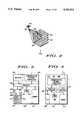
- FIG. 1shows a layout diagram of an environment within which the present invention is practiced
- FIG. 2shows a layout diagram of a cellular antenna pattern achieved by satellites configured in accordance with the teaching of the present invention
- FIG. 3shows a block diagram of a mobile unit
- FIG. 4shows a block diagram of a switching office and of a subscriber information manager
- FIG. 5shows a table of messages sent between various entities included in the environment illustrated in FIG. 1;
- FIG. 6shows a data structure maintained within switching offices to support the messages described by FIG. 5;
- FIG. 7shows a data structure maintained within subscriber information managers to support the messages described by FIG. 5;
- FIGS. 8-14show flow charts of procedures performed by the mobile units to support call setup within the environment illustrated in FIG. 1;
- FIGS. 15-27show flow charts of procedures performed by switching offices to support call setup within the environment illustrated in FIG. 1;
- FIGS. 28-32show flow charts of procedures performed by subscriber information managers to support call setup within the environment illustrated in FIG. 1.
- FIG. 1shows a layout diagram of an environment 100 configured in accordance with a preferred embodiment of the present invention.
- a constellation 102consisting of several satellites 104 is placed in a relatively low orbit around the earth 106.
- Environment 100additionally includes one or more switching offices (SOs) 400.
- SOs 400reside on the surface of earth 106 and are in data communication with nearby ones of satellites 104 through RF communication links 110. Satellites 104 are also in data communication with one another through data communication links 112. Hence, through constellation 102 of satellites 104, a SO 400 may control communications delivered to any size region of the earth 106. However, the region controlled by each SO 400 is preferably associated with one or more specific geo-political jurisdictions.
- SOs 400couple to public switched telecommunication networks (PSTNs) 114, from which calls directed toward subscribers of environment 100 may be received and to which calls placed by subscribers of environment 100 may be sent.
- PSTNspublic switched telecommunication networks
- Environment 100also includes any number, potentially in the millions, of mobile units (MUs) 300.
- MUs 300may be configured as conventional portable radio communication equipment. Environment 100 accommodates the movement of MUs 300 anywhere within the confines of earth 106, whether on or near the surface or in the atmosphere above earth 106. However, nothing requires MUs 300 to move, and environment 100 operates satisfactorily if a portion of the entire population of MUs 300 remains stationary.
- MUs 300are configured to receive communications from satellites 104 and to perform other functions which are discussed below. MUs 300 communicate with nearby satellites 104 through communication channels 116.
- SIMssubscriber information managers
- Each SIM 118maintains a subscriber database that is relevant to only a discrete portion of the population of MUs 300.
- one SIM 118is associated with each SO 400.
- a SIM 118 and a SO 400may utilize the same computerized hardware.
- a SIM 118 and a SO 400are separated logically rather than physically.
- Each SO 400may communicate with any SIM 118 through constellation 102, PSTN 114, or internal computer structures when a SO 400 communicates with its logical partner SIM 118.
- MUs 300determine, at least in part, their own locations.
- MUs 300utilize a satellite positioning system 120, such as the Global Positioning System (GPS), in making this determination.
- System 120includes a constellation of artificial satellites which orbit the earth.
- System 120 satellitesmay be the same or different than satellites 104.
- the satellites of system 120are different than satellites 104, but this is not essential.
- MUs 300use conventional techniques to monitor and process signals transmitted by system 120 to determine their own locations. For convenience of explanation, the operation of system 120 is described below for a GPS position locating system. However, the use of a GPS position locating system is not intended to limit the present invention, and those skilled in the art will understand that other position locating systems may be used.
- environment 100may be viewed as including a network 122 through which MUs 300 communicate.
- Network 122is formed from constellation 102 of satellites 104, SOs 400, and SIMs 118.
- Callsmay be setup between an originating MU (OMU) and a destination MU (DMU), calls may be setup between an OMU and a destination PSTN phone number, and calls may be setup between a PSTN phone number and a DMU.
- OMUoriginating MU
- DMUdestination MU
- each MU 300engages in control communications with a nearby SO 400 through constellation 102. These control communications take place prior to forming a communication path between a MU 300 and another unit, which may be another MU 300 or a PSTN phone number.
- a MU 300communicates with the SO 400 via one or more satellites 104.
- This SO 400may be considered the serving SO for that particular MU 300.
- OSOorigination SO
- DSOdestination SO
- Satellites 104Due to the low earth orbits, satellites 104 constantly move relative to the earth 106. If, for example, satellites 104 are placed in orbits which are around 765 km above earth 106, then an overhead satellite 104 travels at a speed of around 25,000 km/hr with respect to a point on the surface of earth 106. This allows a satellite 104 to be within view of a point on the surface of the earth 106 for a maximum period of around nine minutes. Due to the relatively low orbits of satellites 104, line-of-sight electromagnetic transmissions from any one satellite cover a relatively small area of the earth 106 at any point in time. For example, when satellites 104 occupy orbits at around 765 km above the earth, such transmissions cover areas around 4075 km in diameter.
- FIG. 2shows a layout diagram of a cellular antenna pattern achieved by satellites 104.
- each satellite 104includes an array 202 of directional antennas.
- Each array 202projects numerous discrete antenna patterns on the earth's surface at numerous diverse angles away from its satellite 104.
- FIG. 2shows a diagram of a resulting pattern of cells 204 that satellites 104 collectively form on the surface of earth 106.
- a region 206which is bounded by a double line in FIG. 2, results from the antenna patterns produced by an antenna array 202 of a single satellite 104.
- Cells 204 which reside outside of region 206are produced by antenna arrays 202 from other satellites 104.
- cells 204With satellites 104 traveling at speeds of up to 25,000 km/hr with respect to the earth 106, cells 204 also travel over the earth at close to this speed. At this speed, any given point on the surface of the earth resides within a single cell 204 for no more than around one minute.
- Satellites 104communicate with MUs 300 over links 116 using numerous frequency channels.
- satellites 104 and MUs 300may desirably employ a frequency division multiple access (FDMA) scheme so that numerous independent communication links may be established simultaneously.
- FDMAfrequency division multiple access
- the entire spectrum of these numerous frequency channelsis available within each cell.
- a seven-cell frequency reuse patterndepicted in FIG. 2, is implemented using time division multiple access (TDMA) techniques to prevent interference between adjacent cells.
- TDMAtime division multiple access
- framesare defined to include at least seven different time slots to correspond to the seven-cell reuse pattern.
- FIG. 2illustrates a seven-cell, seven time slot arrangement, those skilled in the art will understand that a larger or smaller reuse pattern can also be used.
- TDMA communication schemeis established at satellites 104.
- satellites 104move at speeds of up to 25,000 km/hr, Doppler shift and time slot synchronization parameters between a MU 300 and a satellite 104 constantly change.
- satellites 104are configured as moving repeaters. In other words, satellites 104 do little more than receive data communication messages from one source and pass these messages on to a destination. None requires all of communication links 110, 112, and 116 to be similar in frequency and/or timing protocol parameters. Thus, satellites 104 may also re-package messages received from one communication link into a format compatible with another link before passing the messages on. In addition, satellites 104 may include components which help resolve Doppler and timing shift parameters in connection with the operation of links 110, 112, and 116. Satellites 104 may advantageously communicate such parameters to the entities with which they communicate, such as MUs 300, SOs 400, and other satellites 104, to help in maintaining synchronization with links 110, 112, and 116.
- Satellites 104preferably serve the role of a repeater in a call setup process.
- the intelligence required to identify and assign network resourcesis preferably shared to a large extent between MUs 300, SOs 400, and SIMs 118. This allows the design of satellites 104 to remain relatively simple. As a consequence, the weight, power, and design requirements of satellites 104 are lessened and the costs associated with satellites 104 are reduced. Moreover, possible failures related to call setup are more likely to be located on the ground where they may be corrected at less expense.
- Those skilled in the artare well aware of devices which act as repeaters. Since satellites 104 act as repeaters, their structure and operation need not be discussed in detail herein.
- FIG. 3shows a block diagram of a mobile unit 300.
- Mobile unit 300includes a communication network transceiver 302 which transmits and receives signals in a format compatible with satellites 104 and network 122 (see FIG. 1). These signals include data messages which allow MU 300 to be in data communication with a nearby satellite 104. Through this satellite 104, MU 300 is also in data communication with any other node of network 122, such as a nearby SO 400.
- a position location receiver 304 of MU 300as for example a GPS receiver, receives the signals broadcast by positioning system 120 and generates data describing the current location of MU 300.
- Transceiver 302 and receiver 304both couple to a processor 306.
- Processor 306additionally couples to an input/output (I/O) section 308, a timer 310, and a memory 312.
- I/Oinput/output
- Memory 312includes data which serve as instructions to processor 306 and which, when executed by processor 306, cause MU 300 to carry out call setup procedures which are discussed below.
- memory 312includes variables, tables, and databases that are manipulated due to the operation of MU 300.
- I/O section 308 of MU 300is used to collect inputs from a user of MU 300 and to provide outputs for the user to perceive.
- Section 308includes, for example, a keypad 314 which is used to collect numbers that identify a party to whom a call may be directed.
- a power switch 316is used to control the energization and de-energization of MU 300.
- a send key 318is used to indicate when a called party's number has been entered, and a hook switch 320 is used in a conventional sense.
- a display 322is used to present visual information to the user, and an alarm or beeper 324 is used to provide an audible alert to the user.
- a handset, or multitone, 326transforms audible signals into electrical signals, and vice-versa.
- FIG. 4shows a block diagram of a SO 400.
- SO 400includes a transceiver 402 which transmits and receives signals in a format compatible with satellites 104. These signals carry data messages which allow SO 400 to communicate with a nearby satellite 104, with MUs 300 that the SO 400 is currently serving, with other SOs 400 that the SO 400 may be cooperating with in setting up a call, and with any SIM 118 within network 122.
- Transceiver 402couples to a processor 404.
- Processor 404also couples to an I/O section 406, a timer 408, a memory 410, and a PSTN interface 412.
- I/O section 406receives input from keyboards and other input devices and provides data to display terminals, printers, and other output devices.
- Processor 404uses timer 408 to maintain the current date and time.
- Memory 410includes semiconductor, magnetic, and other storage devices for storing data that serve as instructions to processor 404 and which, when executed by processor 404, cause SO 400 to carry out procedures which are discussed below.
- memory 410includes variables, tables, and databases that are manipulated due to the operation of SO 400.
- SO 400communicates with the PSTN 114.
- FIG. 4also applies to SIMs 118.
- Processor 404, I/O section 406, timer 408, and memory 410may serve the dual role of SO 400 and SIM 118.
- SIM 118 and SO 400will be established through programming instructions stored in memory 410. Accordingly, the diverse logical entities of SO 400 and SIM 118 may operate in the same physical hardware.
- FIGS. 5-7present information which describes messages sent between MUs 300, SOs 400, and SIMs 118 in support of the call setup process and which describe data structures that are maintained, at least in part, to support call setup.
- FIG. 5columns are shown for message names, data conveyed by particular messages, and entities such as MUs 300, SOs 400, and SIMs 118 that play a role in connection with the messages.
- the table of FIG. 5includes separate columns for MU, OMU, and DMU to distinguish the various roles a MU 300 may play in connection with setting up a call.
- the MU columnis relevant to messages which are not related to a particular call
- the OMU columnis relevant when a MU 300 is originating a particular call
- the DMU columnis relevant when a MU 300 is the destination of a particular call.
- SO, OSO, and DSO columnsare provided to distinguish the various roles that a SO 400 may play in connection with a call.
- the SO columnis relevant to messages that are not related to a particular call
- the OSO columnis relevant when a SO 400 is playing a role near an originating end of a call being setup
- the DSO columnis relevant when a SO 400 is playing a role near a destination end of a call being setup.
- FIGS. 8-14show flow charts of procedures performed by MUs 300 to support call setup
- FIGS. 15-27show flow charts of procedures performed by SOs 400 to support call setup
- FIGS. 28-32show flow charts of procedures performed by SIMs 118 to support call setup.
- Detailed discussions of the messages and data elements shown in FIGS. 5-7are presented below where appropriate in connection with the procedures shown in FIGS. 8-32.
- Those skilled in the artwill appreciate that the procedures discussed below in connection with FIGS. 8-32 are controlled by programming instructions placed in memories 312 and 410 of MUs 300, SOs 400, and SIMs 118.
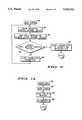
- FIG. 8shows a Power On procedure 800 performed by any MU 300 upon energization.
- a task 802is among the first tasks performed by MU 300 within procedure 800.
- MU 300determines its current location.
- MU 300may utilize positioning system 120 to determine its location, or any other positioning technique.
- the determination of locationis performed automatically, without receiving any information from a user of MU 300.
- a process 900is performed to gain synchronization with link 116 to a nearby satellite 104.
- FIG. 9shows a flow chart of Gain Synch procedure 900.
- procedure 900allows a MU 300 to communicate with network 122.
- network 122through satellites 104, provides numerous channels which may be used for communication within link 116.
- One of these channelsis a broadcast control channel (BCCH).
- BCCHbroadcast control channel
- the BCCHis continuously transmitted for receipt by MUs 300.
- a MU 300may perform an initial form of synchronization and obtain data that describes the satellite's identity and cell number.
- a task 904sends a "hello" message to this satellite on a random access channel (RACH).
- RACHrandom access channel
- the hello messageattempts to inform the satellite 104 of the MU's identity.
- the random access channel(s)are preferably operated in accordance with a multiple access technique known to those skilled in the art, such as a conventional carrier sense multiple access technique (CSMA) or the like.
- CSMAcarrier sense multiple access technique
- task 904sends the hello message only if the RACH appears to be silent at the time of transmission.
- MU 300monitors the BCCH in a query task 906 to detect any messages that might be directed to the MU 300. If, after a predetermined period of time, a message is not detected on the BCCH, a task 908 alters transceiver parameters and routes program control back to task 902 to again attempt to communicate with the satellite 104. Those skilled in the art will appreciate that task 908 may adjust frequency parameters to compensate for Doppler and may adjust timing parameters to compensate for a lack of time slot synchronization. By remaining in the loop of tasks 902-908 and adjusting frequency and timing parameters at task 908 in a systematic manner, the satellite 104 will eventually be able to detect the hello message and will respond with a message addressed to the MU 300 on the BCCH.
- this messageWhen this message is received, it will identify the MU 300 and convey the fact that the MU 300 has gained synchronization. This message will also inform the MU 300 of the parameters needed to more precisely adjust frequency and timing parameters of transceiver 302 for efficient communication. In the preferred embodiment, it instructs the MU 300 to begin communication operations on a specified control channel (CCH) of link 116. Accordingly, after receipt of this message, a task 910 is performed to adjust transceiver 302 to operate on the specified channel. Synchronization has been achieved, and duplex communication may now take place over this CCH.
- CCHcontrol channel
- a task 804causes a Log-On message 502 (see FIG. 5) to be sent to a nearby SO 400.
- Log-On message 502includes a value (MU ID) which uniquely identifies the MU 300 sending message 502 and the location of the MU 300.
- Log-On message 502may additionally include an encrypted authentication code which can be used in deciding whether to allow MU 300 to gain access to network 122.
- the sending of any message, whether message 502 or otherwise, by any entity within environment 100, whether MU 300 or otherwise,may include waiting for the receipt of an appropriate acknowledgment message. If an acknowledgement is not received within a predetermined period of time, then the message may be repeated. Likewise, the receipt of any message may include the transmission of an appropriate acknowledgement message in response to the received message. Such details are appreciated by those skilled in the art and are not discussed further herein.
- MU 300After sending Log-On message 502, MU 300 performs a task 806 to enable a maintain synchronization (synch) mode of operation and waits at a query task 808 until a Log-On-Response message 504 is received over the CCH.
- the maintain synch mode of operationcauses the frequency and timing parameters programmed into transceiver 302 to track Doppler and timing characteristics of the moving nodes, or satellites 104, of network 122. This mode will be discussed in more detail below in connection with FIG. 10.
- a task 810disables the maintain synch mode of operation, and a query task 812 evaluates Log-On-Response message 504 to determine whether access to network 122 has been granted.
- synchronization with the CCHwill soon be lost by MU 300 due to the movement of satellites 104.
- resources of network 122are conserved so that they may be used by other MUs.
- MU 300may continue to track the BCCH.
- FIG. 10shows a flow chart of Background procedure 1000.
- Procedure 1000is performed in a background mode by MU 300.
- procedure 1000continuously operates even though other tasks not related to procedure 1000 are being performed in generally the same time frame.
- a task 1002utilizes timer 310 to maintain a time-of-day clock.
- a task 1004determines the current location of MU 300 in the same manner as task 802, discussed above.
- a query task 1006determines whether a Location-Update message 506 needs to be sent to network 122.
- Message 506reports the current location of MU 300 to network 122. As will be discussed below, this location data is retained at a serving SO 400 and in a home SIM 118 for the MU 300.
- message 506is sent on a regular schedule, such as every few hours.
- message 506is sent when MU 300 travels a predetermined distance from a location which was previously reported to network 122.
- network 122sends data describing a border to MU 300, and MU 300 sends Location-Update message 506 only when MU 300 passes over the border characterized by the border data.
- message 506is sent when MU 300 loses its ability to track the BCCH for a predetermined period of time.
- DMU 300may lose its ability to track the BCCH when it is carried into a basement or some other structure which interferes with reception.
- Task 1006evaluates an account (discussed below) which is kept of BCCH unavailability. In each embodiment, task 1006 evaluates some sort of threshold to determine if MU 300 has exceeded the threshold. When one of such thresholds is exceeded, the MU's location is reported to network 122.
- Gain Synch procedure 900is performed to allow MU 300 to communicate with network 122, and a task 1008 sends Location-Update message 506 over the CCH obtained through procedure 900.
- Message 506conveys the ID of MU 300 and data describing the current location of MU 300.
- program controlproceeds back to task 1002, or optionally (not shown) to a task 1010.
- query task 1010determines whether the maintain synch mode of operation, discussed above, is enabled. If this mode of operation is not enabled, then program control returns to task 1002 to complete a program loop.
- a query task 1012determines whether a timer has expired to indicate that a stay-alive message should be sent to satellite 104 so that synchronization may be maintained.
- satellites 104are placed in the above-discussed low earth orbits which cause them to move at a rate of around 25,000 km/hr, frequency and timing adjustments to transceiver 302 are desirably made around every 500 msec.
- a task 1014sends the stay-alive message over the currently active CCH. The stay-alive message identifies the MU 300.
- MU 300receives the gained-synch message, which provides parameters to use in making timing and frequency adjustments to transceiver 302. After adjusting transceiver 302 to maintain synchronization with the CCH, program control loops back to task 1002.
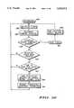
- FIG. 11shows a flow chart of a Standby procedure 1100.
- procedure 1100is performed after MU 300 has been logged on network 122.
- MU 300simply waits for a call to be setup.
- MU 300monitors the BCCH.
- the BCCHis used by network 122 to inform MU 300 of an incoming call.
- Task 1102also keeps an account of the time during which the BCCH cannot be received. When the BCCH may again be received, this account may desirably be reset. This account is used as discussed above in connection with task 1006.
- task 1102monitors I/O section 308 to determine if the user of MU 300 is entering information which will lead to the sending of a call.
- a usermay manipulate keypad 314 to enter a phone number or other identifying code, then press send button 318 to cause the phone number or code to be sent to network 122.
- a switching task 1104responds to a received input that signals a call setup related activity.
- Task 1104routes program control to an appropriate procedure when a call setup related activity occurs. If no call setup activity occurs, task 1102 repeats. If an Incoming-Call message 508 is detected on the BCCH, then a procedure 1200 is performed. If a manipulation of I/O section 308 which instructs MU 300 to place a call is detected, a Send Call procedure 1300 is performed. And, if a manipulation of power switch 316 is detected, a Power Off procedure 1400 is performed. Those skilled in the art will appreciate that task 1104 may additionally recognize other stimulations not related to call setup and route program control accordingly.
- FIG. 12shows a flow chart of Incoming-Call message procedure 1200.
- Procedure 1200is performed whenever MU 300 receives Incoming-Call message 508. This message is received over the BCCH, and includes the MU's ID.
- Message 508informs MU 300 that a call is being setup for MU 300. In other words, MU 300 is the called party in a call.
- MU 300receives the message 508, it acts as a destination MU or DMU 300 for the purposes of FIG. 12.
- procedure 1200performs Gain Synch procedure 900, discussed above.
- DMU 300can communicate with network 122 over a CCH.
- a task 1202After gaining synchronization with the CCH, a task 1202 sends a Unit-Found message 510 to its serving SO 400.
- the SO 400 serving DMU 300controls the destination end of the call being setup. Hence, this SO 400 will be referred to as DSO 400 for the purposes of FIG. 12.
- Unit-Found message 510conveys the identity of DMU 300 and informs DSO 400 that the DMU 300 to which a call is being placed has now been found. As will be discussed below, this causes network 122 to cease searching for DMU 300.
- a task 1204enables the maintain synch mode of operation discussed above. This will cause DMU 300 to hold the CCH open for future communications.
- a task 1206initiates a ring sequence.
- DMU 300may, for example, initiate the ring sequence by operating beeper 324 so that a ringing signal is produced to alert a user of DMU 300 to the incoming call.
- a query task 1208monitors hook switch 320 to determine when an off-hook condition occurs.
- an off-hook conditionrefers to a user answering the call whether or not an actual hook switch is utilized in making the determination. If the off-hook condition is not detected, then the user has not yet acknowledged the incoming call, and a query task 1210 determines whether a Kill-Call message 512 has been received from network 122 at DMU 300. Kill-Call message 512 informs DMU 300 that the call is being terminated. If no Kill-Call message 512 has been received at DMU 300, program control loops back to task 1208 to wail until either the call is killed or the user answers DMU 300.
- a task 1212disables the maintain synch mode of operation so that DMU 300 will lose synchronization with the CCH and the CCH will be released for use by other MUs.
- a task 1214stops the ringing sequence because the user need not now be alerted to an incoming call. After task 1214, program control returns to Standby procedure 1100 to await the next call setup related event.
- task 1208routes program control to a task 1216.
- Task 1216stops the ringing sequence because the user need no longer be alerted to the incoming call.
- a task 1218sends an Off-Hook message 514 to DSO 400 over the CCH.
- Message 514carries the MU ID of DMU 300 and informs DSO 400 that the user has answered the call.
- DSO 400allocates the resources needed to connect the call to DMU 300.
- a task 1220waits until a Call-Connected message 516 is received.
- Message 516is directed to DMU 300 and informs DMU 300 that the call is now connected.
- Message 516carries information which informs DMU 300 to tune in a traffic channel (TCH) to use in the upcoming call.
- TCHtraffic channel
- the TCHis a duplex channel that is assigned by satellite 104 in accordance with the current channel availability of satellite 104.
- DMU 300adjusts transceiver 302 to tune in the specified TCH. Once a traffic channel is assigned, real time, continuous communication, given the TDMA scheme discussed above, takes place over the TCH.
- DMU 300may now process the call, as shown at task 1222.
- audio signalsare continuously obtained from handset 326, digitized, vocoded, packetized to conform to the TDMA protocol of the TCH, and transmitted over the TCH to network 122.
- data packetsare continuously received over the TCH, decoded, and presented in audible form at handset 326.
- DMU 300continuously monitors hook switch 320 to determine if the user of DMU 300 ends the call and monitors TCH for Kill-Call message 512, which would also inform DMU 300 that the call has ended.
- DMU 300sends Kill-Call message 512 to network 122.
- program controlreturns to Standby procedure 1100 to await the next call setup related event.
- FIG. 13shows a flow chart of Send Call procedure 1300.
- Procedure 1300is performed when a user has instructed MU 300 to originate a call to another unit or party.
- MU 300receives instructions to originate a call by a user, it acts as an origination MU, or OMU 300 for the purposes of FIG. 13.
- Procedure 1300performs Gain Synch procedure 900, discussed above.
- OMU 300can communicate with network 122 over a CCH.
- a task 1302sends an Outgoing-Call message 518 to its serving SO 400 over the CCH.
- the SO 400 serving OMU 300controls the origination end of the call being setup. Hence, this SO 400 will be referred to as 400 for the purposes of FIG. 13.
- Outgoing-Call message 518conveys the identity of OMU 300 and informs OSO 400 that OMU 300 wishes to setup a call.
- Message 518additionally conveys a code that identifies the destination party.
- This codemay be a phone number for a device coupled to PSTN 114 or another code which identifies a DMU 300.
- DMUs 300are uniquely identified using a series of digits which conform to telephone numbering standards. As will be discussed below, this causes OSO 400 to initiate control communications related to setting up the requested call.
- a task 1304enables the maintain synch mode of operation so that the CCH will remain open for future communications.
- a task 1306begins some sort of user feedback.
- the user feedbackmay be a conventional ringing tone, or may be some other automated recording which informs the user that progress is being made in setting up the requested call.
- a query task 1308determines whether Call-Connected message 516 has been received yet at OMU 300. If the Call-Connected message has not been received, a query task 1310 monitors I/O section 308, for example hook switch 320 of section 308, to determine whether the user has decided to terminate the call. If a call termination condition is not indicated, program control loops back to task 1308. Procedure 1300 continues to loop through tasks 1308-1310 until OMU 300 receives Call-Connected message 516 or until the user of OMU 300 terminates the call. Of course, those skilled in the art will appreciate that MUs 300 may be designed so that portions of I/O section 308 other than hook switch 320 can be used to signal a call termination.
- a task 1312stops the user feedback which was begun above in task 1306, and a task 1314 sends Kill-Call message 512 to OSO 400 over the CCH.
- a task 1316is performed to disable the maintain synch mode of operation so that OMU 300 will soon lose synchronization with the CCH and the CCH will become available for use by other MUs 300.
- program controlreturns to Standby procedure 1100 to await the next call setup related event.
- a task 1318adjusts transceiver 302 to the traffic channel (TCH) specified by message 516.
- TCHtraffic channel
- a task 1320stops the user feedback started above in task 1306. The call has now been connected, and may be processed as discussed above in connection with process 1222. Upon completion of the call, program control returns to Standby procedure 1100 to await the next call setup related event.
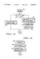
- FIG. 14shows a flow chart of Power Off procedure 1400, which is performed when a command to turn MU 300 off is detected from I/O section 308.
- Procedure 1400performs Gain Synch procedure 900, discussed above.
- MU 300can communicate with network 122 over a CCH.
- a task 1402After gaining synchronization with the CCH, a task 1402 sends a Log-Off message 520 to network 122.
- Message 520carries the identity of the logging off MU 300 and informs network 122 that the MU 300 is powering down.
- network 122uses Log-On and Log-Off messages 502 and 520, respectively, to keep track of whether a MU 300 is available to receive calls. By determining when a MU 300 is not available to receive calls because of being powered off, network 122 is generally able to block the setting up of calls to powered off MUs 300 at an early stage in the call setup process. This conserves network resources because the call setup process is prevented from progressing to near completion in such circumstances.
- a task 1404de-energizes MU 300. When MU 300 is again powered up, it will begin performing Power On procedure 800, discussed above.
- FIGS. 15-27show flow charts of procedures performed by SO 400 in support of the call setup process.
- SO 400receives and responds to various messages to support the call setup process. Messages can be received from MUs 300 which are logging on or logging off network 122. Messages can be received from OMUs 300, which are attempting to originate a call, and from DMUs 300 to which calls are being directed. Messages may be received at DSOs 400 from OSOs 400, and vice-versa, to support call setup. And messages may be received from SIMs 118 in response to call setup related messages directed to SIMs 118. SOs 400 send various messages to these entities in response to the messages that are received.
- SOs 400with support from SIMs 118, possess the bulk of the intelligence used in setting up calls in environment 100.
- the role of the moving nodes provided by satellites 104is simply to serve substantially as repeaters for transferring messages between MUs 300 and serving SOs 400.
- SOs 400may engage in numerous other activities related to the operation of network 122.
- the preferred embodiment of the present inventionplaces the bulk of call setup intelligence in SOs 400, those skilled in the art will appreciate that some of the features described herein as taking place in SOs 400 may desirably be shifted to satellites 104 in particular applications, and that the precise location of this intelligence is of lesser importance than the functions achieved thereby.
- FIG. 15shows a flow chart of a SO Executive procedure 1500 which SO 400 performs in support of the call setup process.
- Procedure 1500examines messages received at SO 400 and switches program control to an appropriate procedure to respond to the received message.
- Those skilled in the artwill appreciate that all procedures controlled by procedure 1500 may be reentrant. Hence, numerous diverse ones of these procedures may be in progress at any given time with respect to one or more calls being setup, and at any single point in time each of these procedures may be in progress multiple times with respect to different calls.
- FIGS. 16-27present flow charts of these procedures.
- FIG. 16shows a flow chart of a Log-On message procedure 1600.
- SO 400performs procedure 1600 when a Log-On message 502, discussed above in connection with MU procedure 800, is received.
- the receipt of a Log-On message 502indicates that a MU 300 is attempting to access network 122 to receive communication services.
- Procedure 1600performs a query task 1602 to authenticate the MU 300.
- Task 1602may advantageously perform a decryption operation on the authentication code, then examine the authentication code by evaluating error detection codes and the like to determine authenticity. If the authentication process concludes that MU 300 is not an authorized subscriber to network 122, then a task 1604 constructs and sends Log-On-Response message 504 back to MU 300. Task 1604 causes message 504 to convey an "access denied" message to MU 300. After task 1604, program control exits procedure 1600.
- By authenticating MUs 300 at SOs 400many unauthorized access attempts may be detected and blocked without consuming further resources of network 122. Such MUs 300 will not be allowed to place calls or receive calls, and such MUs 300 will be blocked without the consumption of a significant amount of network resources.
- a task 1606opens an active subscriber record (ASR) 600 for MU 300.
- ASRactive subscriber record
- FIG. 6shows exemplary data items maintained in an ASR 600.
- One ASR 600is kept in a database for each active subscriber.
- SO 400generally communicates with those MUs 300 that are located within its region of jurisdiction. Accordingly, ASRs 600 for all active MUs 300 within environment 100 are distributed throughout the SOs 400 within environment 100.
- Task 1606marks a status data element 602 of the just-opened ASR 600 to indicate a pending status. This indicates that the MU 300 is not yet logged on network 122.
- task 1606saves the location data carried by Log-On message 502 in a location data element 604 of ASR 600. The ID of the MU 300 sending the Log-On message 502 is saved in a data element 606.
- ASRs 600may be arranged or otherwise linked with other information so that they may be quickly accessed given a MU ID value. Moreover, nothing prevents network 122 from substituting a local or temporary ID for the unique system-wide MU ID.
- a task 1608determines the "home" SIM (HSIM) 118 for the MU 300 sending Log-On message 502.
- the HSIMis the SIM 118 to which that MU 300 is assigned. It may not be the SIM 118 associated with the SO 400 serving the region in which the MU 300 is currently located.
- the HSIM determinationmay advantageously be made by evaluating the MU ID.
- MU IDsare assigned so that a particular field of the MU ID (4-10 bits for example) identifies the HSIM for that MU 300. Thus, by examining this field the SO 400 receiving the Log-On message 502 may identify the MU's HSIM 118.
- Log-On message 502is sent on to the HSIM 118 at a task 1610.
- the sending of message 502, or any other message within the call setup process, on to HSIM 118, or any other entity within network 122,does not imply that the message is unaltered. Rather, an entity may add, delete, or alter data conveyed by the message without changing the basic thrust of the message.
- task 1610adds data to message 502 that identifies the SO 400 sending the message to HSIM 118. That way HSIM 118 may know the address of the SO 400 to which a response is directed. In one embodiment, SO 400 may simply replace the location data carried by message 502 with its own ID.
- SOs 400are responsible for their own jurisdictions, their IDs serve as location data, albeit not as precise, for the HSIMs 118.
- SO 400may remove the authentication code from message 502 if HSIM 118 does not rely on this code in performing its validation of MU 300.
- program controlexits from procedure 1600 and returns to SO Executive procedure 1500.
- FIG. 17shows a flow chart of a Log-On-Response message procedure 1700.
- SO 400performs procedure 1700 when a Log-On-Response message 504, discussed above in connection with MU procedure 800, is received.
- Message 504is received at a SO 400 from a HSIM 118.
- Message 504indicates whether the MU 300 identified therein has been granted access to network 122. If MU 300 has been granted access, message 504 carries data descriptive of MU 300 which are relevant to setting up calls for MU 300.
- Procedure 1700performs a task 1702 to determine if an ASR 600 exists for the MU 300 to which message 504 is directed. Message 504 carries a MU ID which task 1702 may use in accessing the appropriate record. If no ASR 600 is present, a task 1704 determines an appropriate repeater area to use in sending the Log-On-Response message on to the MU 300. In the preferred embodiment where satellites 104 represent repeaters, task 1704 determines an appropriate routing code or satellite 104 and cell 204 to use for transmitting message 504 to MU 300. Task 1704 then sends the Log-On-Response message 504 on to the MU 300. When no ASR exists for a MU 300, the Log-On-Response message 504 is configured to tell MU 300 that access to network 122 is denied. After task 1704, program control exits procedure 1700 and returns to Executive procedure 1500.
- a query task 1706examines the message 504 received from HSIM 118 to determine whether access to network 122 has been granted. If access has not been granted, a task 1708 purges or removes the ASR 600 for this MU and program control proceeds to task 1704, discussed above, to inform MU 300 that access has been denied.
- Location data 604 from the removed ASR 600may be used in determining which satellite 104 to use in sending message 504 on to MU 300.
- a task 1710When task 1706 determines that message 504 conveys access granted information, a task 1710 marks status data element 602 of ASR 600 as being active or logged on. This active status will be interpreted as a not busy state. Task 1710 also obtains features data from message 504 and saves this data in a features data element 608 of ASR 600.
- the featuresdescribe various communication service options which have been subscribed to for MU 300. Such features may include, for example, a service priority level, a ring through feature, a call forward feature, a conference call feature, or any other feature conventionally known in connection with telephony.
- task 1704again sends Log-On-Response message 504 on to MU 300. This time, task 1704 configures message 504 to communicate an access granted message. Moreover, task 1704 may desirably remove the features from message 504 before sending it on to MU 300 if such data are of no use to MU 300.
- FIG. 18shows a flow chart of a Location-Update message procedure 1800.
- SO 400performs procedure 1800 when a Location-Update message 506, discussed above in connection with MU procedure 1000, is received.
- Message 506is received at a SO 400 from a MU 300.
- Message 506identifies a MU 300 that is currently logged on network 122 and provides current location data for the MU 300.
- Procedure 1800performs a task 1802 to obtain the location data from message 506 and save the location data in the MU's ASR 600.
- an optional task 1804determines the HSIM for MU 300 and sends message 506 on to that HSIM 118.
- the location data sent on to HSIM 118need not be identical to the location data supplied to SO 400.
- the location data sent from SO 400 to HSIM 118may, for example, simply identify the SO 400 within whose jurisdiction MU 300 currently resides.
- procedure 1800may additionally examine the location data and refrain from passing message 506 on to HSIM 118 if the location data to be passed on to HSIM 118 would be substantially identical to location data already recorded at HSIM 118.
- program controlexits procedure 1800 and returns to Executive procedure 1500.
- FIG. 19shows a flow chart of a Log-Off message procedure 1900.
- SO 400performs procedure 1900 when a Log-Off message 520, discussed above in connection with MU procedure 1400, is received.
- Message 520is received at a SO 400 from a MU 300.
- Message 520identifies a MU 300 that is currently logged on network 122.
- Procedure 1900performs a task 1902 to remove or purge the MU's ASR 600 from the database of ASRs 600. As a result of purging ASR 600, calls will not be received from or directed to that MU 300 until another Log-On message 502 is received.
- a task 1904is performed to determine the HSIM 118 to which MU 300 is assigned and to send Log-Off message 520 on to that HSIM 118.
- program controlexits procedure 1900 and returns to Executive procedure 1500.
- FIG. 20shows a flow chart of an Outgoing-Call message procedure 2000.
- SO 400performs procedure 2000 when an Outgoing-Call message 518, discussed above in connection with MU procedure 1300, is received.
- Message 518is received at a SO 400 from a MU 300 that is attempting to originate a call (an OMU).
- Message 518identifies OMU 300 and provides a destination ID, which identifies the party being called.
- Procedure 2000is also performed when a call is received from PSTN 114.
- SO 400performs procedure 2000, it acts as a call originating SO (OSO).
- OSOcall originating SO
- Procedure 2000initially performs a task 2002.
- task 2002marks status data element 602 of the OMU's ASR 600 as being busy.
- task 2002initializes a call record for the upcoming call.
- This call recordpreferably includes data conventionally included in telephony call records. Such call records are used for billing purposes and for obtaining network usage statistics.
- Task 2002may additionally set a busy alarm.
- the busy alarmrepresents a timer which will expire at a predetermined time and provide a busy alarm message to Executive procedure 1500. This alarm is set so that if the call cannot be setup within a predetermined period of time, OMU 300 will receive a busy signal.
- a query task 2004determines whether the destination ID included with message 518 indicates a PSTN number or an ID of another MU 300 (a DMU).
- a task 2006performs a table look-up operation to determine which DSO 400 serves the phone number.
- a task 2008sends a Ring message 522 from the OSO 400 performing task 2008 to this DSO 400. Ring message 522 conveys an ID for the OSO 400 sending message 522 and the destination ID of the party being called.
- program controlexits procedure 2000 and returns to Executive procedure 1500.
- SO 400may serve the roles of OSO and DSO for a single call.
- messagesWhen messages are sent between an OSO and a DSO that are actually the same SO 400, they may simply be placed in a message queue managed by Executive procedure 1500. Such messages will be processed by SO 400 in due course.
- a query task 2009investigates the ASR database of OSO 400 to determine if it includes an ASR 600 for DMU 300. A large percentage of calls are made locally. Thus, a large probability exists that OSO 400 can also serve as DSO 400. If an ASR 600 exists for DMU 300, then DMU 300 has been located and SO 400 may serve the roles of both OSO and DSO. If an ASR 600 exists for DMU 300, task 2008 is performed to send Ring message 522 to DSO 400 by placing message 522 in the message queue managed by Executive procedure 1500. For a large percentage of calls placed to DMUs 300, task 2009 saves network resources and reduces call setup time because it eliminates the need for additional network communications.
- a task 2010determines the HSIM 118 to which the DMU 300 is assigned. As discussed above, this determination may be made by evaluating a portion of the DMU's ID. After task 2010, a task 2012 sends a Locate-Unit message 524 to that HSIM 118. Message 524 will cause that HSIM 118 to respond by telling OSO 400 of the location of DMU 300 so that OSO 400 may then continue with the call setup process.
- network 122may be used in communicating the message.
- one HSIM 118 and one SO 400represent diverse logical entities that are embodied in one set of physical hardware. Accordingly, in this embodiment task 2012 may desirably evaluate the address of the HSIM 118 to which the message is directed. If that HSIM 118 is the logical partner of the OSO 400 performing task 2012, OSO 400 may simply place the message in an appropriate queue for the partner HSIM 118 for evaluation in due course.
- program controlexits procedure 2000 and returns to Executive procedure 1500.
- FIG. 21shows a flow chart of a Ring message procedure 2100.
- SO 400performs procedure 2100 when a Ring message 522, discussed above in connection with Outgoing-Call Message procedure 2000, is received.
- Message 522is received at a SO 400 from an OSO 400 that is attempting to originate a call.
- Message 522is routed to a SO 400 because the SO 400 has been determined to be the destination SO 400 (DSO) for a call that is being setup.
- DSO 400may provide access to PSTN 114 or a DMU 300.
- Message 522carries data that identify the OSO 400 which sent message 522 and provide a destination ID. The destination ID identifies the party being called.
- Procedure 2100initially performs a query task 2102.
- Task 2102examines the destination ID carried by message 522 to determine whether the call is destined for PSTN 114 or a DMU 300. If the call is destined for a PSTN phone number, a task 2104 processes the call in a manner consistent with the requirements of the PSTN. For example, task 2104 may desirably "dial" the phone number indicated by the destination ID from message 522. Of course, those skilled in the art will appreciate that dialing a phone number includes the application of dual tone multifrequency (DTMF) or other signaling tones to PSTN 114. A call record may be initialized to keep track of the call for billing and statistical purposes.
- DTMFdual tone multifrequency
- the PSTNmay be monitored to determine whether a busy signal, a ringing signal, or an answer results from dialing the PSTN phone number. If a busy signal is detected, then a Ring-Failure message 526 may be returned to OSO 400. Ring-Failure message 526 will be discussed in more detail below. If the call is answered, Call-Connected message 516 may be returned to OSO 400.
- a query task 2106examines the ASR database of DSO 400 to determine if an ASR 600 for the identified DMU 300 indicates that a call may be placed to the DMU 300. The call may not be cleared for placement to the identified DMU 300 for several reasons. For example, no ASR 600 may exist for the DMU 300, or the DMU's ASR 600 may indicate a pending or busy status at data element 602. Features data element 608 may be evaluated to determine if DMU 300 does not have a ring-through feature. If any of these conditions are detected, then a task 2108 sends Ring-Failure message 526 back to OSO 400. Message 526 preferably includes the DMU's ID and a code which describes the type of Ring-Failure encountered. After task 2108, program control exits procedure 2100 and returns to Executive procedure 1500.
- a task 2110When task 2106 determines that the DMU's ASR 600 exists and permits a call to be placed to DMU 300, a task 2110 initializes a call record, as discussed above in connection with task 2002. Next, a task 2112 determines a repeater area to use in sending an Incoming-Call message 508 to DMU 300. When the mobile repeater nodes of network 122 are satellites 104 that project cells 204 on earth 106, task 2112 determines a satellite and cell to utilize in sending Incoming-Call message 508 to DMU 300. This determination may be made using the location data 604 stored in the DMU's ASR 600, the current time, and a list of satellite positions versus time.
- task 2112determines which satellite 104 to use in sending message 508 to DMU 300, and that satellite 104 determines the cell(s) to use in locating DMU 300.
- a task 2114sends Incoming-Call message 508.
- message 508carries the ID of DMU 300, is broadcast over a satellite's broadcast control channel (BCCH), and informs the identified DMU 300 of the incoming call.
- BCCHbroadcast control channel
- Network 122may not be able to precisely predict which satellite(s) and cell(s) are best for use in sending message 508.
- the lack of precisionmay be due to the fact that a DMU 300 has moved since it supplied network 122 with location data.
- the DMU 300may be in a location which, at the instant that message 508 is to be sent to DMU 300, is near the borders of the areas covered by a cell 204 or satellite 104.
- the call setup process of the present inventioncontemplates the use of a searching technique to provide adequate assurances that DMU 300 will receive message 508.
- a query task 2116determines whether the search for DMU 300 is now finished.
- the searchmay be finished when either DMU 300 sends Unit-Found message 510 to DSO 400, discussed below, or when network 122 concludes that DMU 300 probably cannot be reached at the current time and that further attempts will waste an excessive amount of network resources.
- DMU 300may not be reachable for various reasons. For example, DMU 300 may have been carried into a basement or other structure which interferes with reception.
- a first attempt at sending message 508may desirably be directed to the cell 204 where location data 604 of ASR 600 places DMU 300. If Unit-Found message 510 is not received within a predetermined period of time, typically on the order of 200 msec. or less, then the six cells 204 that surround this cell may be used, either concurrently or in succession, in sending message 508. If Unit-Found message 510 is still not returned, task 2116 may, but need not, conclude that the search is now done.
- task 2116concludes that the search is finished, program control proceeds in one of two different directions. If the search finishes because Unit-Found message 510 has been received, then program control simply exits procedure 2100 and returns to Executive procedure 1500. If the search finishes because no Unit-Found message 510 has been received after several different cells 204 have been used in sending Incoming-Call message 508 to DMU 300, program control proceeds to task 2108. Task 2108 sends Ring-Failure message 526 back to OSO 400.
- FIG. 22shows a flow chart of a Locate-Unit-Response message procedure 2200.
- SO 400performs procedure 2200 when a Locate-Unit-Response message 528 is received from a HSIM 118.
- a SO 400 acting as an OSOreceives a request to setup a call to a DMU 300, it sends Locate-Unit message 524 to the DMU's HSIM 118 to learn the DMU's current location.
- Locate-Unit-Response message 528is the HSIM's response to Locate-Unit message 524.
- SO 400performs procedure 2200, it is acting in its OSO capacity.
- Locate-Unit-Response message 528carries the DMU's ID. It also carries at least one of two other items of information. If DMU 300 is logged on network 122, message 528 conveys the location of DMU 300. If DMU 300 is not logged on network 122, message 528 conveys the fact that it is not logged on.
- Procedure 2200initially performs a query task 2202.
- Task 2202examines the received message 528 to determine if a call is possible. A call is considered not possible if the DMU 300 to which the call is directed is logged off network 122, in which case the DMU 300 cannot be reached.
- a call setup failure routine 2204is performed. Routine 2204 first desirably performs a task 2206, which sends a message to the party attempting to place the call. This party may be OMU 300 or a PSTN device. Task 2206 may be omitted for a PSTN placed call. The message sent in task 2206 may cause satellite 104 and OMU 300 to assign a channel over which real time voice communication may take place.
- a task 2208plays or initiates an appropriate call failure recording over an appropriate channel if to an OMU 300 or to a PSTN line if to a PSTN device.
- the recordingmay, for example, verbally inform the caller that the called party cannot be reached at the present time.
- a task 2210After task 2208 has played or initiated the recording (which may be stored internally in the OMU), a task 2210 sends Kill-Call message 512 if the call is being placed by OMU 300. Task 2210 interrupts or "hangs up" the PSTN line if the call is being placed by a PSTN device.
- a task 2212finalizes and sends the call record previously initialized in connection with this call, as discussed above in connection with task 2002.
- the call recordneed not be sent at once but may be collected with other call records and sent in a batch at a convenient time.
- the call recordis preferably sent to a node of network 122 which is designated for collecting and processing call records originated by OSO 400.
- a task 2214updates the call record established for this call and determines which SO 400 is the DSO for this call. This determination may be made by examining the location data carried by message 528. As discussed above, this location data may desirably represent the address of the SO 400 that is currently serving the DMU 300. However, OSO 400 may convert any other format of location data, such as latitude/longitude data, into an address for DSO 400 through a table look-up operation.
- a task 2216sends Ring message 522 to DSO 400.
- Ring message 522was discussed above in connection with procedures 2000 and 2100.
- DSO 400receives message 522, it performs Ring message procedure 2100, discussed above.
- program controlexits procedure 2200 and returns to Executive procedure 1500.
- FIG. 23shows a flow chart of a Unit-Found message procedure 2300.
- SO 400performs procedure 2300 when a Unit-Found message 510 is received from a DMU 300.
- a DMU 300receives Incoming-Call message 508, it responds with Unit-Found message 510.
- Unit-Found message 510conveys the identity of DMU 300.
- Procedure 2300performs a task 2302 to send Unit-Found message 510 on to the OSO 400 if SO 400 is acting the part of the call's DSO.
- a task 2304updates the call record kept by DSO 400 and stops any searching for DMU 300 being performed by tasks 2112-2114 of procedure 2100.
- an OSO 400 receiving message 510may update its call record and alter any user feedback it is providing to the person originating the call.
- program controlexits procedure 2300 and returns to Executive procedure 1500.
- FIG. 24shows a flow chart of an Off-Hook message procedure 2400.
- SO 400performs procedure 2400 when an Off-Hook message 514 is received from a DMU 300.
- a DMU 300responds with Off-Hook message 514 when a user of DMU 300 answers the call.
- Off-Hook message 514conveys the identity of DMU 300.
- a task 2402sends Off-Hook message 514 on to OSO 400.
- DSO 400may append a routing code to message 514. This routing code can be used in routing call traffic to DMU 300.
- OSO 400will then perform procedure 2400.
- OSO 400may perform task 2402 to provide a routing code for use in routing call traffic to OMU 300 to the destination end of the call.
- a task 2404updates the call record to indicate that the call is now being established and stops any busy alarms, discussed above in connection with task 2002, that may be set with respect to this call.
- a task 2406sends Call-Connected message 516 to the MU 300 being serviced.
- MU 300is the DMU when a DSO 400 performs procedure 2400 and the OMU when an OSO 400 performs procedure 2400.
- message 516will, when received at the OMU and DMU, include data that assigns a traffic channel (TCH) to the call.
- TCHtraffic channel
- the traffic channels used by an OMU and DMUare governed by the satellites 104 with which the OMU and DMU are communicating, and the OMU and DMU will have their own respective traffic channels.
- This assignment datamay be determined by the SOs 400 or by the satellites 104 which are currently involved in the call and directly communicating with the MUs 300.
- program controlexits procedure 2400 and returns to Executive procedure 1500.
- the callis now setup from the perspective of SOs 400. Those skilled in the art will appreciate that the call itself need not be routed through the SOs 400 which control the call.
- FIG. 25shows a flow chart of a Ring-Failure message procedure 2500.
- SO 400performs procedure 2500 when a Ring-Failure message 526 is received from a DSO 300.
- a DSO 400sends Ring-Failure message 526 to OSO 400 when it determines that the call cannot be setup.
- Message 526conveys the ID of DMU 300 and an indication of the reason why the call cannot be setup.
- Procedure 2500performs call failure routine 2204, discussed above.
- the recording played at task 2208 within routine 2204may desirably indicate a cause for not being able to setup the call.
- program controlexits procedure 2500 and returns to Executive procedure 1500.
- FIG. 26shows a flow chart of a Kill-Call message procedure 2600.
- SO 400performs procedure 2600 when a Kill-Call message 512 is received.
- Message 512may be received from a MU 300 or another SO 400 and may be received while SO 400 is acting as an OSO or a DSO.
- Kill-Call message 512indicates that the call setup process, or call if it is in progress, needs to be terminated.
- Procedure 2600performs a task 2602 to finalize and send the call record SO 400 has been making with respect to the present call.
- a task 2604stops all in-progress processes related to the call. Such processes may, for example, be the search for DMU 300 discussed above in connection with procedure 2100, the busy alarm discussed above in connection with procedure 2000, or the playing of a recording in task 2208 of routine 2204.
- a task 2606sends the Kill-Call message 512 on to either its served MU 300 or partner SO 400 in the present call.
- program controlexits procedure 2600 and returns to Executive procedure 1500.
- FIG. 27shows a flow chart of a Busy Alarm procedure 2700.
- SO 400acts as an OSO when it performs procedure 2700.
- Procedure 2700is performed when a busy alarm message is received.
- the busy alarm messageis generated internally by OSO 400 when a timing condition is met.
- a busy alarmis set when a call is being originated. If the call cannot be setup by the time that the busy alarm message is received, then procedure 2700 is performed.
- a task 2702identifies the OMU 300 to which the busy alarm message relates.
- procedure 2700performs call failure routine 2204, discussed above.
- the recording played at task 2208 in routine 2204may simply play a conventional busy tone or may play a voice message which explains the problem encountered in setting up the call.
- program controlexits procedure 2700 and returns to Executive procedure 1500.
- FIGS. 28-32show flow charts of procedures performed by SIM 118 in support of the call setup process.
- a SIM 118maintains a database of subscriber records 700, as shown in FIG. 7, related to only a portion of the entire population of MUs 300.
- the SIMis considered the home SIM 118 (HSIM).
- SIM 118receives and responds to various messages to support the call setup process. These messages are received from SOs 400. Some messages may be passed on to SIM 118 from MUs 300 and other messages are originated at SOs 400.
- SIMs 118may engage in numerous other activities related to the operation of network 122 other than call setup.
- FIG. 28shows a flow chart of a SIM Executive procedure 2800 which SIM 118 performs in support of the call setup process.
- Procedure 2800examines messages received at SIM 118 and switches program control to an appropriate procedure to respond to the received message.
- FIGS. 29-32present flow charts of these procedures.
- FIG. 29shows a flow chart of a Log-On message procedure 2900.
- SIM 118performs procedure 2900 when a Log-On message 502, discussed above in connection with MU procedure 800 and SO procedure 1600, is received.
- the receipt of Log-On message 502indicates that a MU 300 is attempting to access network 122 to receive communication services.
- Procedure 2900performs a task 2902 to look up the subscriber record 700 for the MU 300 identified by message 502.
- a query task 2904determines whether task 2902 was successful in finding the MU's subscriber record 700. If no subscriber record is present, a task 2906 constructs and sends Log-On-Response message 504 back to the SO 400 which passed Log-On message 502 on to SIM 118. Message 504 will communicate the fact the MU 300 is considered invalid and that access is denied by network 122.
- program controlexits procedure 2900 and returns to SIM Executive procedure 2800. The MU 300 is not logged on network 122, and the MU 300 will not receive communication services through network 122.
- a task 2908saves or updates, in a data element 702 of subscriber record 700, the location data that Log-On message 502 provides.
- a query task 2910determines whether MU 300 is valid.
- the validity check of task 2910serves a purpose similar to that of the authentication test discussed above in connection with SO procedure 1600.
- Subscriber record 700may include a data element 704 which task 2910 accesses and which conveys validation parameters. Data element 704 may be supplied by user input through I/O section 406 of SIM 118.
- the validation parametersmay indicate that the subscriber to whom MU 300 is registered is not paying his or her bills for the services offered by network 122.
- validation parametersmay indicate that services are not to be allowed when users are located in certain areas, and task 2910 can evaluate these areas with respect to the location data stored in data element 702.
- task 2906is performed to return a Log-On-Response message 504 that denies access to network 122.
- a task 2912When task 2910 determines that MU 300 is a valid MU that should be allowed access to network 122, a task 2912 marks an activation status data element 706 of the MU's subscriber record 700 as being logged on.
- a task 2914constructs and sends Log-On-Response message 504 back to the SO 400 indicated in the received Log-On message 502. This time, Log-On-Response message 504 includes features data from a data element 708 of subscriber record 700. These features are discussed above in connection with SO procedure 1600. The features are entered into the MU's subscriber record 700 when service for MU 300 is initially registered with network 122 or thereafter updated.
- program controlexits procedure 2900 and returns to Executive procedure 2800.
- MU 300is now logged on network 122.
- FIG. 30shows a flow chart of a Locate-Unit message procedure 3000.
- SIM 118performs procedure 3000 when a Locate-Unit message 524 is received.
- an OSO 400sends a SIM 118 message 524 when a call is being setup to a DMU 300.
- Message 524identifies the DMU to whom the call is being placed and the OSO 400 from whom message 524 is being sent.
- Procedure 3000performs a task 3002 to look up the DMU's subscriber record 700.
- a query task 3004determines whether a record 700 exists for DMU 300 and whether the DMU is valid for this call. Validity parameters 704 may be consulted to determine whether the DMU is valid.
- a DMUmay be considered invalid if, for example, the OSO 400 requesting the location of the DMU 300 is located in a region which has not been cleared to communicate to a MU 300 located where DMU 300 is currently located.
- a task 3006constructs and sends Locate-Unit-Response message 528, discussed above in connection with SO procedure 2200. Message 528 is sent to the OSO 400 that sent the received Locate-Unit message 524. In this situation, message 528 conveys the fact that a call may not be setup to the specified DMU 300.
- a query task 3008determines whether MU 300 is currently logged on network 122. This determination may be made by examining data element 706 of the DMU's subscriber record 700. If DMU 300 is not logged on, task 3006 sends message 528 to convey the fact that DMU 300 is not available for receiving calls and that a call may not be setup to DMU 300.
- a task 3010obtains location data from data element 702 of the specified DMU's subscriber record 700, and a task 3012 formats and sends Locate-Unit-Response message 528 to the OSO 400 that sent the received Locate-Unit message 524.
- Task 3012includes the location data obtained in task 3010 in message 528 and conveys the fact that DMU 300 is currently logged on network 122.
- program controlexits procedure 3000 and returns to Executive procedure 2800.
- FIG. 31shows a flow chart of a Location-Update message procedure 3100.
- SIM 118performs procedure 3100 when a Location-Update message 506 is received.
- a MU 300originates Location-Update message 506 from time to time to automatically inform network 122 of its current location.
- Message 506identifies the MU 300 which is reporting its location and includes data describing its current location.
- Procedure 3100performs a task 3102 to look up a subscriber record 700 for the MU 300 making the location report. Presumably, a record 700 exists because such location reports are made while MU 300 is logged on network 122. However, those skilled in the art will appreciate that various error checking and reporting schemes can be implemented in accordance with task 3102 to address mistakes.
- a task 3104saves the location data included with message 506. Task 3104 saves this location data in the MU's subscriber record 700 at data element 702.
- program controlexits procedure 3100 and returns to Executive procedure 2800.
- FIG. 32shows a flow chart of a Log-Off message procedure 3200.
- SIM 118performs procedure 3200 when it receives a Log-Off message 520.
- a MU 300originates Log-Off message 520 before it de-energizes to automatically inform network 122 that it is not going to be available to receive calls.
- Message 520identifies the MU 300 which is reporting its logging off condition.
- Procedure 3200performs a task 3202 to look up a subscriber record 700 for the MU 300 making the logging off report. Record 700 presumably exists because logging off reports are made from MUs 300 that are logged on network 122.
- a task 3204marks activation status data element 706 of the MU's subscriber record 700 as being logged off.
- program controlexits procedure 3200 and returns to Executive procedure 2800. Until MU 300 logs back on network 122, calls directed to MU 300 will be blocked through procedure 3000 without consuming additional network resources.
- the present inventionprovides an improved call setup process which is adapted for use with mobile end users.
- MUs 300automatically determine their current locations and report these locations to network 122.
- Network 122keeps track of these locations and makes this information available to the relevant OSOs 400 which are attempting to setup calls to DMUs 300.
- the call setup process of the present inventionis adapted for use in connection with a network 122 having mobile nodes, such as satellites 104.
- the location informationis used by SOs 400 in making initial selections regarding which of numerous available mobile node resources to use for communication with MUs 300.
- the bulk of call setup intelligenceis preferably retained in SOs 400 and SIMs 118, which are more easily serviced that orbiting satellites 104.
- the call setup process of the present inventionis also adapted to conserve network resources and to complete call setup quickly.
- Each message communicated within environment 100consumes some of the resources of network 122.
- the total number of messages communicated in setting up callsis minimized in the present invention.
- Information, such as validity and features, supporting call setupis maintained at outlying SOs 400 which are serving MUs 300 rather than being held at HSIMs 118. Accordingly SOs 400 may setup many types of calls quickly and without consulting a HSIM 118. When calls cannot be setup, the decisions to declare setup process failures are made quickly and with few internal network communications.
- messages and data elements discussed hereinmay include additional information not specifically discussed herein. Date and time stamps are likely candidates to be included in such additional information even though such stamps have no direct bearing on call setup.
- alternate position determining systemssuch as LORAN or other systems and methods known to those skilled in the art, may be utilized by MUs 300 in determining their locations.
- the mobile repeater nodes of network 122need not be limited to satellites but may be terrestrial or airborne nodes.
Landscapes
- Engineering & Computer Science (AREA)
- Computer Networks & Wireless Communication (AREA)
- Signal Processing (AREA)
- Physics & Mathematics (AREA)
- General Physics & Mathematics (AREA)
- Astronomy & Astrophysics (AREA)
- Aviation & Aerospace Engineering (AREA)
- Radar, Positioning & Navigation (AREA)
- Remote Sensing (AREA)
- Mobile Radio Communication Systems (AREA)
- Exchange Systems With Centralized Control (AREA)
- Radio Relay Systems (AREA)
Abstract
Description
Claims (35)
Priority Applications (7)
| Application Number | Priority Date | Filing Date | Title |
|---|---|---|---|
| US07/859,206US5343512A (en) | 1992-03-27 | 1992-03-27 | Call setup method for use with a network having mobile end users |
| CA002089116ACA2089116C (en) | 1992-03-27 | 1993-02-09 | Call setup method for use with a network having mobile end users |
| DE69332258TDE69332258T2 (en) | 1992-03-27 | 1993-03-11 | Method for operating a home subscriber information manager |
| EP93103903AEP0562374B1 (en) | 1992-03-27 | 1993-03-11 | Method of operating a home subscriber information manager |
| AT93103903TATE223632T1 (en) | 1992-03-27 | 1993-03-11 | METHOD FOR OPERATING A HOME PARTICIPANT INFORMATION MANAGER |
| JP5087781AJPH0847040A (en) | 1992-03-27 | 1993-03-24 | Call setting method for using in network having mobile end user |
| RU93004692ARU2139631C1 (en) | 1992-03-27 | 1993-03-25 | Method for establishing communications in network with mobile terminal users |
Applications Claiming Priority (1)
| Application Number | Priority Date | Filing Date | Title |
|---|---|---|---|
| US07/859,206US5343512A (en) | 1992-03-27 | 1992-03-27 | Call setup method for use with a network having mobile end users |
Publications (1)
| Publication Number | Publication Date |
|---|---|
| US5343512Atrue US5343512A (en) | 1994-08-30 |
Family
ID=25330344
Family Applications (1)
| Application Number | Title | Priority Date | Filing Date |
|---|---|---|---|
| US07/859,206Expired - LifetimeUS5343512A (en) | 1992-03-27 | 1992-03-27 | Call setup method for use with a network having mobile end users |
Country Status (7)
| Country | Link |
|---|---|
| US (1) | US5343512A (en) |
| EP (1) | EP0562374B1 (en) |
| JP (1) | JPH0847040A (en) |
| AT (1) | ATE223632T1 (en) |
| CA (1) | CA2089116C (en) |
| DE (1) | DE69332258T2 (en) |
| RU (1) | RU2139631C1 (en) |
Cited By (83)
| Publication number | Priority date | Publication date | Assignee | Title |
|---|---|---|---|---|
| US5469158A (en)* | 1992-04-20 | 1995-11-21 | Sumitomo Electric Industries, Ltd. | Apparatus for correcting the detected heading of a vehicle |
| US5483664A (en)* | 1993-07-26 | 1996-01-09 | Motorola, Inc. | Cellular communications with scheduled handoffs |
| US5500648A (en)* | 1993-08-11 | 1996-03-19 | Motorola, Inc. | Geolocation responsive radio telecommunication system and method therefor |
| WO1996010896A1 (en)* | 1994-10-03 | 1996-04-11 | Motorola Inc. | Satellite-based ring alert apparatus and method of use |
| US5528247A (en)* | 1993-07-07 | 1996-06-18 | Mitsubishi Denki Kabushiki Kaisha | Mobile satellite communication system |
| US5539924A (en)* | 1994-03-10 | 1996-07-23 | Motorola, Inc. | Method for providing communications within a geographic region |
| US5548801A (en)* | 1993-02-10 | 1996-08-20 | Kokusai Denshin Denwa Kabushiki Kaisha | System for determining and registering location of mobile terminal for communication system with non-geosynchronous satellites |
| US5555257A (en)* | 1994-01-11 | 1996-09-10 | Ericsson Ge Mobile Communications Inc. | Cellular/satellite communications system with improved frequency re-use |
| US5561836A (en)* | 1994-05-02 | 1996-10-01 | Motorola, Inc. | Method and apparatus for qualifying access to communication system services based on subscriber unit location |
| US5564017A (en)* | 1994-06-30 | 1996-10-08 | International Business Machines Corporation | Procedure for safely terminating network programs during network logoff |
| US5584046A (en)* | 1994-11-04 | 1996-12-10 | Cornell Research Foundation, Inc. | Method and apparatus for spectrum sharing between satellite and terrestrial communication services using temporal and spatial synchronization |
| US5608410A (en)* | 1993-05-07 | 1997-03-04 | Associated Rt, Inc. | System for locating a source of bursty transmissions cross reference to related applications |
| US5641134A (en)* | 1994-12-27 | 1997-06-24 | Motorola, Inc. | Satellite cellular telephone and data communication system at an inclined orbit |
| US5659544A (en)* | 1994-10-17 | 1997-08-19 | Lucent Technologies Inc. | Method and system for distributed control in wireless cellular and personal communication systems |
| US5666647A (en)* | 1992-08-03 | 1997-09-09 | Motorola, Inc. | Remote position determination |
| US5689803A (en)* | 1995-08-25 | 1997-11-18 | Motorola, Inc. | Dial-back call completion method and apparatus in a radio-communication system |
| US5742908A (en)* | 1994-09-14 | 1998-04-21 | Ericsson Inc. | Frequency error correction in a satellite-mobile communications system |
| US5788187A (en)* | 1992-06-02 | 1998-08-04 | Mobile Communications Holdings, Inc. | Elliptical orbit satellite, system, and deployment with controllable coverage characteristics |
| US5790073A (en)* | 1996-03-13 | 1998-08-04 | Motorola, Inc. | Radio telecommunication network with fraud-circumventing registration |
| US5802454A (en)* | 1995-12-15 | 1998-09-01 | Teletrac, Inc. | Remotely distributed location and messaging system |
| US5809396A (en)* | 1996-03-29 | 1998-09-15 | Motorola, Inc. | Radio telecommunication network with selectable ring signal coverage |
| US5809418A (en)* | 1995-08-25 | 1998-09-15 | Motorola, Inc. | Position-dependent call connection method and apparatus in a radio-communication system |
| US5815809A (en)* | 1996-04-16 | 1998-09-29 | Amsc Subsidiary Corporation | Mobile earth terminal communication device providing voice, data, facsimile, and/or roaming communication features |
| USRE35916E (en)* | 1991-12-26 | 1998-10-06 | Dennison; Everett | Cellular telephone system that uses position of a mobile unit to make call management decisions |
| US5822312A (en)* | 1995-08-30 | 1998-10-13 | Com Dev Limited | Repeaters for multibeam satellites |
| US5825325A (en)* | 1995-12-21 | 1998-10-20 | Com Dev Limited | Intersatellite communications systems |
| US5841352A (en)* | 1997-06-18 | 1998-11-24 | Prakash; Sushil | Child monitor |
| US5850602A (en)* | 1995-08-15 | 1998-12-15 | Tisdale; William R. | Communication protocol for mobile earth terminal communication device used in mobile satellite communication system |
| US5852825A (en)* | 1994-12-05 | 1998-12-22 | Trimble Navigation Limited | Form data message formatting method, program and system |
| US5867765A (en)* | 1995-03-31 | 1999-02-02 | Telefonaktiebolaget Lm Ericsson | Non-geostationary satellite mobile communication system integration with network principles for terrestrial cellular |
| US5905956A (en)* | 1996-06-25 | 1999-05-18 | Motorola, Inc. | Method for identifying active handsets in a cordless telephone system |
| US5907809A (en)* | 1994-01-11 | 1999-05-25 | Ericsson Inc. | Position determination using multiple base station signals |
| US5918174A (en)* | 1996-03-29 | 1999-06-29 | Ericsson, Inc. | Circuitry and method for initiating communication between communication stations of a radio communication system |
| US5920803A (en)* | 1995-09-05 | 1999-07-06 | Motorola, Inc. | Method and apparatus for message delivery in a communication system having orbiting transmitters |
| US5930713A (en)* | 1997-05-28 | 1999-07-27 | Telefonaktiebolaget L M Ericsson (Publ) | Proactive communication of mobile station position information following inter-exchange handoff |
| US5940742A (en)* | 1994-01-11 | 1999-08-17 | Ericsson Inc. | Two-way paging system and apparatus |
| US5946611A (en)* | 1991-12-26 | 1999-08-31 | Sycord Limited Partnership | Cellular telephone system that uses position of a mobile unit to make call management decisions |
| US5995823A (en)* | 1997-07-09 | 1999-11-30 | Nortel Networks Corporation | Method and system in a wireless communications network for providing toll restrictions based on the geographic location of an originator |
| US6047162A (en)* | 1997-09-25 | 2000-04-04 | Com Dev Limited | Regional programming in a direct broadcast satellite |
| US6055426A (en)* | 1997-06-17 | 2000-04-25 | Highwaymaster Communications, Inc. | Notification of a mobile unit out of coverage |
| US6091959A (en)* | 1999-06-02 | 2000-07-18 | Motorola, Inc. | Method and apparatus in a two-way wireless communication system for location-based message transmission |
| US6122759A (en)* | 1995-10-10 | 2000-09-19 | Lucent Technologies Inc. | Method and apparatus for restoration of an ATM network |
| US6138015A (en)* | 1995-08-30 | 2000-10-24 | Siemens Aktiengesellschaft | Multi-cell radio system with PBX periphery assemblies |
| US6148041A (en)* | 1994-01-11 | 2000-11-14 | Ericsson Inc. | Joint demodulation using spatial maximum likelihood |
| US6157811A (en)* | 1994-01-11 | 2000-12-05 | Ericsson Inc. | Cellular/satellite communications system with improved frequency re-use |
| US6195555B1 (en)* | 1994-01-11 | 2001-02-27 | Ericsson Inc. | Method of directing a call to a mobile telephone in a dual mode cellular satellite communication network |
| US6201967B1 (en)* | 1996-09-09 | 2001-03-13 | Ico Services Ltd | Communications apparatus and method |
| US6249675B1 (en)* | 1998-08-07 | 2001-06-19 | At&T Corporation | Method and apparatus for network paging |
| US6278861B1 (en) | 1995-08-15 | 2001-08-21 | Motient Services Inc. | Mobile earth terminal with roaming capability |
| US20010026552A1 (en)* | 2000-03-11 | 2001-10-04 | Spratt Michael P. | Limiting message diffusion between mobile devices |
| US20020026289A1 (en)* | 2000-06-30 | 2002-02-28 | Soshiro Kuzunuki | Multimedia information delivery system and mobile information terminal device |
| US6438386B2 (en)* | 1997-07-14 | 2002-08-20 | Hughes Electronics Corporation | Immediate channel assignment in a wireless system |
| US20030045291A1 (en)* | 2001-08-29 | 2003-03-06 | Nec Corporation | Mobile communications system, mobile station, control method and recording medium |
| US6542716B1 (en)* | 1994-01-11 | 2003-04-01 | Ericsson Inc. | Position registration for cellular satellite communication systems |
| US20030073404A1 (en)* | 1995-06-12 | 2003-04-17 | Alcatel Espace | Non-geostationary satellite communication system and satellite, station and terminal included therein |
| US6654362B1 (en) | 1999-11-24 | 2003-11-25 | Lucent Technologies, Inc. | Use of location in handoff in wireless communication systems |
| US6658246B1 (en)* | 1999-06-28 | 2003-12-02 | Alcatel | System for and a method of controlling access to a service available via a telecommunications terminal connected to a telecommunications network |
| US20040008637A1 (en)* | 1993-07-30 | 2004-01-15 | Seligsohn Sherwin I. | High efficiency sub-orbital high altitude telecommunications system |
| US20040023617A1 (en)* | 1991-05-13 | 2004-02-05 | Mahany Ronald L. | Radio frequency local area network |
| GB2393357A (en)* | 2002-09-23 | 2004-03-24 | Inmarsat Ltd | Routing of data packets in a hybrid satellite communication system |
| US20040073933A1 (en)* | 1991-05-13 | 2004-04-15 | Gollnick Charles D. | Network supporting roaming, sleeping terminals |
| US20040125753A1 (en)* | 1995-06-07 | 2004-07-01 | Mahany Ronald L. | Hierarchical communication system providing intelligent data, program and processing migration |
| US20040166895A1 (en)* | 1993-08-31 | 2004-08-26 | Koenck Steven E. | Modular, portable data processing terminal for use in a communication network |
| US6847822B1 (en) | 1991-12-26 | 2005-01-25 | Sycord Limited Partnership | Cellular telephone system that uses position of a mobile unit to make call management decisions |
| US6853849B1 (en)* | 1996-05-30 | 2005-02-08 | Sun Microsystems, Inc. | Location/status-addressed radio/radiotelephone |
| US6868270B2 (en) | 1994-01-11 | 2005-03-15 | Telefonaktiebolaget L.M. Ericsson | Dual-mode methods, systems, and terminals providing reduced mobile terminal registrations |
| US20050078647A1 (en)* | 1991-10-01 | 2005-04-14 | Meier Robert C. | Radio frequency local area network |
| US20050102443A1 (en)* | 1991-05-13 | 2005-05-12 | Mahany Ronald L. | Radio frequency local area network |
| US20050193134A1 (en)* | 2002-04-23 | 2005-09-01 | Jari Syrjala | Method for logging a user out of a service |
| US20050250558A1 (en)* | 1997-07-16 | 2005-11-10 | Ico Services Limited | Satellite mobile telephone cell departure prediction |
| US7068676B1 (en)* | 1999-04-30 | 2006-06-27 | Fujitsu Limited | Wireless terminal device and node device |
| US20070026894A1 (en)* | 2005-07-29 | 2007-02-01 | Peter Zatloukal | Multiple processor communication circuit cards and communication devices that employ such cards |
| US20070168675A1 (en)* | 2006-01-18 | 2007-07-19 | Per Wahlberg | Systems and methods for tracking mobile terrestrial terminals for satellite communications |
| US20070167132A1 (en)* | 2006-01-18 | 2007-07-19 | Per Wahlberg | Systems and methods for collecting and processing satellite communications network usage information |
| US20070178833A1 (en)* | 2006-01-18 | 2007-08-02 | Per Wahlberg | Systems and methods for satellite communications with mobile terrestrial terminals |
| US20080045146A1 (en)* | 2006-01-18 | 2008-02-21 | Per Wahlberg | Systems and methods for establishing modular and flexible satellite communications networks |
| US20080089282A1 (en)* | 2006-08-23 | 2008-04-17 | Malladi Durga P | Acquisition in frequency division multiple access systems |
| US20090092070A1 (en)* | 1992-11-02 | 2009-04-09 | Broadcom Corporation | Radio frequency local area network |
| US20090190550A1 (en)* | 2005-08-01 | 2009-07-30 | Andrea Giustina | Handover information sent over a public wide area network (e.g. internet) |
| US7583639B2 (en) | 1993-05-11 | 2009-09-01 | Broadcom Corporation | System and method for determining data rate |
| US20110125807A1 (en)* | 2008-07-14 | 2011-05-26 | Jonathan Bland | Method and Apparatus for a Subscriber Database |
| US20110191187A1 (en)* | 2008-10-01 | 2011-08-04 | Nokia Corporation | Finding mobile station for device-to-device communication |
| US20120239744A1 (en)* | 2011-03-14 | 2012-09-20 | Qualcomm Atheros, Inc. | Hybrid networking simple-connect setup using proxy device |
Families Citing this family (41)
| Publication number | Priority date | Publication date | Assignee | Title |
|---|---|---|---|---|
| JP3002077B2 (en)* | 1993-08-12 | 2000-01-24 | ケイディディ株式会社 | Mobile satellite communication system using orbiting satellites |
| US5666648A (en)* | 1993-11-09 | 1997-09-09 | Leo One Ip, L.L.C. | Polar relay system for satellite communication |
| CA2134395A1 (en)* | 1993-11-26 | 1995-05-27 | Keith Andrew Olds | Method and apparatus for management of automatically initiated communication |
| US5490087A (en)* | 1993-12-06 | 1996-02-06 | Motorola, Inc. | Radio channel access control |
| US5619209A (en)* | 1994-01-14 | 1997-04-08 | Trw Inc. | User paging for mobile satellite communications |
| TW239242B (en)* | 1994-03-28 | 1995-01-21 | Leo One Ip L L C | Satellite system using equatorial & polar orbit relays |
| DE69519523T2 (en)* | 1994-10-12 | 2001-04-05 | Leo One Ip, L.L.C. | TRANSMISSION ARRANGEMENT WITH LOW-HEIGHT SATELLITES AND OPTIMAL EARTH LIGHTING FOR A TELECOMMUNICATION NETWORK WITH STORAGE AND CIRCUIT |
| GB2295296A (en) | 1994-11-18 | 1996-05-22 | Int Maritime Satellite Organiz | Mobile satellite communications system |
| US5757916A (en)* | 1995-10-06 | 1998-05-26 | International Series Research, Inc. | Method and apparatus for authenticating the location of remote users of networked computing systems |
| US5890062A (en)* | 1996-05-16 | 1999-03-30 | Trw Inc. | Satellite-based cellular telecommunications system utilizing a multiple registration location register |
| US5970416A (en)* | 1996-07-31 | 1999-10-19 | Motorola | Provision of distributed call handling over a plurality of network nodes |
| GB2316831B (en)* | 1996-08-24 | 2000-09-06 | Int Mobile Satellite Org | Improved user terminal access in satellite communication systems |
| GB2316832B (en)* | 1996-08-24 | 2001-05-16 | Ico Services Ltd | Signal assessed user terminal system access in satellite communication systems |
| US5926758A (en)* | 1996-08-26 | 1999-07-20 | Leo One Ip, L.L.C. | Radio frequency sharing methods for satellite systems |
| GB2317074B (en) | 1996-09-09 | 1998-10-28 | I Co Global Communications | Communications apparatus and method |
| NL1004578C2 (en)* | 1996-11-20 | 1998-05-25 | I G P B V | A method of establishing a connection in a satellite system and a satellite system suitable for performing such a method. |
| US6108318A (en)* | 1997-03-04 | 2000-08-22 | Ericsson Inc | System and method for data link synchronization |
| GB2325115B (en)* | 1997-03-25 | 2000-07-05 | Ico Services Ltd | Satellite communications terminal location system and method |
| GB2323988A (en) | 1997-04-01 | 1998-10-07 | Ico Services Ltd | Refining a satellite position estimate |
| US5884142A (en)* | 1997-04-15 | 1999-03-16 | Globalstar L.P. | Low earth orbit distributed gateway communication system |
| FR2763188B1 (en)* | 1997-05-07 | 1999-06-11 | Alsthom Cge Alcatel | COMMUNICATION ROUTING METHOD IN A SATELLITE NETWORK, CORRESPONDING TERMINAL AND BASE STATION |
| FI108771B (en)* | 1997-11-05 | 2002-03-15 | Nokia Corp | Method of sending a message to a mobile station |
| RU2169991C2 (en)* | 1998-06-01 | 2001-06-27 | Шитова Елена Юрьевна | Ground mobile multiple-satellite communication station |
| RU2176853C2 (en)* | 1998-12-22 | 2001-12-10 | Коляда Максим Александрович | Ground mobile satellite communication station |
| GB0000528D0 (en)* | 2000-01-11 | 2000-03-01 | Nokia Networks Oy | Location of a station in a telecommunications system |
| US20020193108A1 (en)* | 2001-05-10 | 2002-12-19 | Robinett Robert L. | Multi-mode satellite and terrestrial communication device with position location |
| US6941133B2 (en)* | 2001-05-18 | 2005-09-06 | Qualcomm Inc. | Dynamic loading and creation of functional objects in a wireless device |
| US7359706B2 (en)* | 2001-08-21 | 2008-04-15 | Motorola Inc. | Data transmission for mobile wireless communication devices |
| CN1180575C (en)* | 2002-03-28 | 2004-12-15 | 华为技术有限公司 | A method for centralized management of local area network switching equipment |
| KR100837351B1 (en) | 2002-04-06 | 2008-06-12 | 엘지전자 주식회사 | How to update radio link parameter of mobile communication system |
| US6839542B2 (en)* | 2002-07-22 | 2005-01-04 | Motorola, Inc. | Virtual dynamic cellular infrastructure based on coordinate information |
| US7110377B2 (en)* | 2002-10-10 | 2006-09-19 | Qualcomm Incorporated | Dormant handoff in a packet data network |
| US7536695B2 (en)* | 2003-03-28 | 2009-05-19 | Microsoft Corporation | Architecture and system for location awareness |
| KR100506528B1 (en)* | 2003-08-12 | 2005-08-03 | 삼성전자주식회사 | Mobile terminals control system using digital signature and control method thereof |
| RU2329607C2 (en)* | 2003-12-23 | 2008-07-20 | Телефонактиеболагет Лм Эрикссон (Пабл) | Method and device to control queue buffer |
| KR100584430B1 (en) | 2004-01-31 | 2006-05-26 | 삼성전자주식회사 | Positioning method of mobile terminal |
| JP4652846B2 (en)* | 2004-03-11 | 2011-03-16 | パナソニック株式会社 | Communication terminal device and communication relay method |
| RU2389160C2 (en)* | 2005-10-03 | 2010-05-10 | Телефонактиеболагет Лм Эрикссон (Пабл) | Transmission capacity optimised carrier assignment |
| RU2307466C1 (en)* | 2006-03-17 | 2007-09-27 | Самсунг Электроникс Ко., Лтд. | Method for transferring service of client stations in wireless network by ieee 802.16 standard |
| JP7747005B2 (en)* | 2020-12-09 | 2025-10-01 | ソニーグループ株式会社 | Communication device, communication method, and communication system |
| US12407404B2 (en)* | 2022-11-21 | 2025-09-02 | Skylo Technologies, Inc. | Wireless device activation tracking of a wireless satellite service |
Citations (26)
| Publication number | Priority date | Publication date | Assignee | Title |
|---|---|---|---|---|
| DE448789C (en)* | 1923-06-22 | 1927-08-24 | Carl Gensel Dipl Ing | Motorized pulley |
| US4475010A (en)* | 1983-05-05 | 1984-10-02 | At&T Bell Laboratories | High density cellular mobile radio communications |
| US4491594A (en)* | 1983-03-08 | 1985-01-01 | Eisai Co., Ltd. | Method for treatment of seizures |
| US4491947A (en)* | 1983-05-31 | 1985-01-01 | At&T Bell Laboratories | Technique for dynamic scheduling of integrated circuit- and packet-switching in a multi-beam SS/TDMA system |
| US4494230A (en)* | 1982-06-25 | 1985-01-15 | At&T Bell Laboratories | Fast packet switching system |
| US4512011A (en)* | 1982-11-01 | 1985-04-16 | At&T Bell Laboratories | Duplicated network arrays and control facilities for packet switching |
| US4551833A (en)* | 1983-08-10 | 1985-11-05 | At&T Bell Laboratories | Distributed monitoring of packet transmission delay |
| US4561090A (en)* | 1983-05-18 | 1985-12-24 | At&T Bell Laboratories | Integrated self-checking packet switch node |
| US4611322A (en)* | 1984-08-03 | 1986-09-09 | At&T Bell Laboratories | Traffic load control arrangement and method for a packet switching system |
| US4672656A (en)* | 1983-10-15 | 1987-06-09 | Ant Nachrichtentechnik Gmbh | Method for establishing a radio connection |
| US4677616A (en)* | 1985-09-11 | 1987-06-30 | At&T Company | Flow control scheme for a switching network |
| US4683584A (en)* | 1985-02-07 | 1987-07-28 | American Telephone And Telegraph Company, At&T Bell Laboratories | Directory number translation in a distributed control switching system |
| US4736364A (en)* | 1986-03-12 | 1988-04-05 | American Telephone And Telegraph Company, At&T Bell Laboratories | Switching system control arrangements |
| US4776001A (en)* | 1985-08-27 | 1988-10-04 | Nippon Telegraph And Telephone Corporation | Radio telephone system control apparatus and method |
| US4856048A (en)* | 1987-03-02 | 1989-08-08 | Nippon Telegraph And Telephone Corporation | Mobile communication system |
| US4876738A (en)* | 1986-09-18 | 1989-10-24 | U.S. Philips Corporation | Mobile radio transmission system |
| US4881271A (en)* | 1987-03-20 | 1989-11-14 | Hitachi, Ltd. | Portable wireless communication systems |
| US4907290A (en)* | 1987-05-15 | 1990-03-06 | Datatrak Limited | Mobile transmitter/receiver |
| EP0365885A2 (en)* | 1988-10-28 | 1990-05-02 | Motorola, Inc. | Satellite cellular telephone and data communication system |
| US5043736A (en)* | 1990-07-27 | 1991-08-27 | Cae-Link Corporation | Cellular position locating system |
| US5050234A (en)* | 1989-03-30 | 1991-09-17 | Nec Corp. | Method for connecting a channel between a base station and a mobile station |
| US5055851A (en)* | 1988-05-16 | 1991-10-08 | Trackmobile, Inc. | Vehicle location system |
| US5081703A (en)* | 1990-06-27 | 1992-01-14 | Pactel Corporation | Satellite mobile communication system for rural service areas |
| EP0467651A1 (en)* | 1990-07-19 | 1992-01-22 | Motorola, Inc. | Satellite-based cellular communication system with position aided subscriber unit. |
| US5161248A (en)* | 1989-10-02 | 1992-11-03 | Motorola, Inc. | Method of predicting cell-to-cell hand-offs for a satellite cellular communications system |
| US5187805A (en)* | 1989-10-02 | 1993-02-16 | Motorola, Inc. | Telemetry, tracking and control for satellite cellular communication systems |
Family Cites Families (7)
| Publication number | Priority date | Publication date | Assignee | Title |
|---|---|---|---|---|
| US4144496A (en)* | 1976-03-17 | 1979-03-13 | Harris Corporation | Mobile communication system and method employing frequency reuse within a geographical service area |
| US5303286A (en)* | 1991-03-29 | 1994-04-12 | Space Systems/Loral, Inc. | Wireless telephone/satellite roaming system |
| SU1411985A1 (en)* | 1986-06-18 | 1988-07-23 | Войсковая Часть 32103 | Radio communication system with access on request |
| US4918609A (en)* | 1988-10-11 | 1990-04-17 | Koji Yamawaki | Satellite-based position-determining system |
| GB2228162B (en)* | 1989-02-08 | 1993-05-19 | Philips Electronic Associated | Mobile radio transmission system and a mobile station for use in the system |
| DE4009578C2 (en)* | 1990-03-24 | 2002-12-05 | Motorola Inc | radio system |
| US5249181A (en)* | 1992-03-25 | 1993-09-28 | Motorola, Inc. | Call processing using logical channel assignments |
- 1992
- 1992-03-27USUS07/859,206patent/US5343512A/ennot_activeExpired - Lifetime
- 1993
- 1993-02-09CACA002089116Apatent/CA2089116C/ennot_activeExpired - Lifetime
- 1993-03-11EPEP93103903Apatent/EP0562374B1/ennot_activeExpired - Lifetime
- 1993-03-11DEDE69332258Tpatent/DE69332258T2/ennot_activeExpired - Lifetime
- 1993-03-11ATAT93103903Tpatent/ATE223632T1/ennot_activeIP Right Cessation
- 1993-03-24JPJP5087781Apatent/JPH0847040A/enactivePending
- 1993-03-25RURU93004692Apatent/RU2139631C1/enactive
Patent Citations (28)
| Publication number | Priority date | Publication date | Assignee | Title |
|---|---|---|---|---|
| DE448789C (en)* | 1923-06-22 | 1927-08-24 | Carl Gensel Dipl Ing | Motorized pulley |
| US4494230A (en)* | 1982-06-25 | 1985-01-15 | At&T Bell Laboratories | Fast packet switching system |
| US4512011A (en)* | 1982-11-01 | 1985-04-16 | At&T Bell Laboratories | Duplicated network arrays and control facilities for packet switching |
| US4491594A (en)* | 1983-03-08 | 1985-01-01 | Eisai Co., Ltd. | Method for treatment of seizures |
| US4475010A (en)* | 1983-05-05 | 1984-10-02 | At&T Bell Laboratories | High density cellular mobile radio communications |
| US4561090A (en)* | 1983-05-18 | 1985-12-24 | At&T Bell Laboratories | Integrated self-checking packet switch node |
| US4491947A (en)* | 1983-05-31 | 1985-01-01 | At&T Bell Laboratories | Technique for dynamic scheduling of integrated circuit- and packet-switching in a multi-beam SS/TDMA system |
| US4551833A (en)* | 1983-08-10 | 1985-11-05 | At&T Bell Laboratories | Distributed monitoring of packet transmission delay |
| US4672656A (en)* | 1983-10-15 | 1987-06-09 | Ant Nachrichtentechnik Gmbh | Method for establishing a radio connection |
| US4611322A (en)* | 1984-08-03 | 1986-09-09 | At&T Bell Laboratories | Traffic load control arrangement and method for a packet switching system |
| US4683584A (en)* | 1985-02-07 | 1987-07-28 | American Telephone And Telegraph Company, At&T Bell Laboratories | Directory number translation in a distributed control switching system |
| US4776001A (en)* | 1985-08-27 | 1988-10-04 | Nippon Telegraph And Telephone Corporation | Radio telephone system control apparatus and method |
| US4677616A (en)* | 1985-09-11 | 1987-06-30 | At&T Company | Flow control scheme for a switching network |
| US4736364A (en)* | 1986-03-12 | 1988-04-05 | American Telephone And Telegraph Company, At&T Bell Laboratories | Switching system control arrangements |
| US4876738A (en)* | 1986-09-18 | 1989-10-24 | U.S. Philips Corporation | Mobile radio transmission system |
| US4856048A (en)* | 1987-03-02 | 1989-08-08 | Nippon Telegraph And Telephone Corporation | Mobile communication system |
| US4881271A (en)* | 1987-03-20 | 1989-11-14 | Hitachi, Ltd. | Portable wireless communication systems |
| US4907290A (en)* | 1987-05-15 | 1990-03-06 | Datatrak Limited | Mobile transmitter/receiver |
| US5055851A (en)* | 1988-05-16 | 1991-10-08 | Trackmobile, Inc. | Vehicle location system |
| EP0365885A2 (en)* | 1988-10-28 | 1990-05-02 | Motorola, Inc. | Satellite cellular telephone and data communication system |
| US5050234A (en)* | 1989-03-30 | 1991-09-17 | Nec Corp. | Method for connecting a channel between a base station and a mobile station |
| US5161248A (en)* | 1989-10-02 | 1992-11-03 | Motorola, Inc. | Method of predicting cell-to-cell hand-offs for a satellite cellular communications system |
| US5187805A (en)* | 1989-10-02 | 1993-02-16 | Motorola, Inc. | Telemetry, tracking and control for satellite cellular communication systems |
| US5081703A (en)* | 1990-06-27 | 1992-01-14 | Pactel Corporation | Satellite mobile communication system for rural service areas |
| EP0467651A1 (en)* | 1990-07-19 | 1992-01-22 | Motorola, Inc. | Satellite-based cellular communication system with position aided subscriber unit. |
| US5119504A (en)* | 1990-07-19 | 1992-06-02 | Motorola, Inc. | Position aided subscriber unit for a satellite cellular system |
| US5043736A (en)* | 1990-07-27 | 1991-08-27 | Cae-Link Corporation | Cellular position locating system |
| US5043736B1 (en)* | 1990-07-27 | 1994-09-06 | Cae Link Corp | Cellular position location system |
Cited By (139)
| Publication number | Priority date | Publication date | Assignee | Title |
|---|---|---|---|---|
| US20050086399A1 (en)* | 1991-05-13 | 2005-04-21 | Mahany Ronald L. | Radio frequency local area network |
| US7552246B2 (en) | 1991-05-13 | 2009-06-23 | Broadcom Corporation | Communication network having a plurality of bridging nodes which transmit a beacon to terminal nodes in power saving state that it has messages awaiting delivery |
| US7536167B2 (en) | 1991-05-13 | 2009-05-19 | Broadcom Corporation | Network supporting roaming, sleeping terminals |
| US20040023617A1 (en)* | 1991-05-13 | 2004-02-05 | Mahany Ronald L. | Radio frequency local area network |
| US7457646B2 (en) | 1991-05-13 | 2008-11-25 | Broadcom Corporation | Radio frequency local area network |
| US20040073933A1 (en)* | 1991-05-13 | 2004-04-15 | Gollnick Charles D. | Network supporting roaming, sleeping terminals |
| US7826818B2 (en) | 1991-05-13 | 2010-11-02 | Broadcom Corporation | Network supporting roaming, sleeping terminals |
| US20050102443A1 (en)* | 1991-05-13 | 2005-05-12 | Mahany Ronald L. | Radio frequency local area network |
| US7415548B2 (en) | 1991-05-13 | 2008-08-19 | Broadcom Corporation | Communication network having a plurality of bridging nodes which transmits a polling message with backward learning technique to determine communication pathway |
| US7899951B2 (en) | 1991-05-13 | 2011-03-01 | Broadcom Corporation | Communication network having a plurality of bridging nodes which transmits a polling message with backward learning technique to determine communication pathway |
| US7483397B2 (en) | 1991-10-01 | 2009-01-27 | Broadcom Corporation | Radio frequency local area network |
| US20050078647A1 (en)* | 1991-10-01 | 2005-04-14 | Meier Robert C. | Radio frequency local area network |
| US20090172189A1 (en)* | 1991-10-01 | 2009-07-02 | Broadcom Corporation | Radio frequency local area network |
| US7873343B2 (en) | 1991-10-01 | 2011-01-18 | Broadcom Corporation | Communication network terminal with sleep capability |
| US20060268806A1 (en)* | 1991-10-01 | 2006-11-30 | Meier Robert C | Radio frequency local area network |
| US7558557B1 (en) | 1991-11-12 | 2009-07-07 | Broadcom Corporation | Low-power messaging in a network supporting roaming terminals |
| US20050075114A1 (en)* | 1991-12-26 | 2005-04-07 | Sycord Limited Partnership | Cellular telephone system that uses position of a mobile unit to make call management decisions |
| US6847822B1 (en) | 1991-12-26 | 2005-01-25 | Sycord Limited Partnership | Cellular telephone system that uses position of a mobile unit to make call management decisions |
| US5946611A (en)* | 1991-12-26 | 1999-08-31 | Sycord Limited Partnership | Cellular telephone system that uses position of a mobile unit to make call management decisions |
| USRE35916E (en)* | 1991-12-26 | 1998-10-06 | Dennison; Everett | Cellular telephone system that uses position of a mobile unit to make call management decisions |
| US7289763B2 (en) | 1991-12-26 | 2007-10-30 | Emsat Advanced Geo-Location Technology, Llp | Cellular telephone system that uses position of a mobile unit to make call management decisions |
| US20080014965A1 (en)* | 1991-12-26 | 2008-01-17 | Emsat Advanced Geo-Location Technology, Llc | Cellular telephone system that uses position of a mobile unit to make call management decisions |
| US5469158A (en)* | 1992-04-20 | 1995-11-21 | Sumitomo Electric Industries, Ltd. | Apparatus for correcting the detected heading of a vehicle |
| US5788187A (en)* | 1992-06-02 | 1998-08-04 | Mobile Communications Holdings, Inc. | Elliptical orbit satellite, system, and deployment with controllable coverage characteristics |
| US5666647A (en)* | 1992-08-03 | 1997-09-09 | Motorola, Inc. | Remote position determination |
| US20090323589A1 (en)* | 1992-11-02 | 2009-12-31 | Broadcom Corporation | Radio frequency local area network |
| US7917145B2 (en) | 1992-11-02 | 2011-03-29 | Broadcom Corporation | Radio frequency local area network |
| US20090092070A1 (en)* | 1992-11-02 | 2009-04-09 | Broadcom Corporation | Radio frequency local area network |
| US5548801A (en)* | 1993-02-10 | 1996-08-20 | Kokusai Denshin Denwa Kabushiki Kaisha | System for determining and registering location of mobile terminal for communication system with non-geosynchronous satellites |
| US5608410A (en)* | 1993-05-07 | 1997-03-04 | Associated Rt, Inc. | System for locating a source of bursty transmissions cross reference to related applications |
| US7583639B2 (en) | 1993-05-11 | 2009-09-01 | Broadcom Corporation | System and method for determining data rate |
| US5528247A (en)* | 1993-07-07 | 1996-06-18 | Mitsubishi Denki Kabushiki Kaisha | Mobile satellite communication system |
| US5483664A (en)* | 1993-07-26 | 1996-01-09 | Motorola, Inc. | Cellular communications with scheduled handoffs |
| US20040008637A1 (en)* | 1993-07-30 | 2004-01-15 | Seligsohn Sherwin I. | High efficiency sub-orbital high altitude telecommunications system |
| US8483120B2 (en)* | 1993-07-30 | 2013-07-09 | Sherwin I. Seligsohn | High efficiency sub-orbital high altitude telecommunications system |
| US5500648A (en)* | 1993-08-11 | 1996-03-19 | Motorola, Inc. | Geolocation responsive radio telecommunication system and method therefor |
| US8509260B2 (en) | 1993-08-31 | 2013-08-13 | Broadcom Corporation | Modular, portable data processing terminal for use in a communication network |
| US20040166895A1 (en)* | 1993-08-31 | 2004-08-26 | Koenck Steven E. | Modular, portable data processing terminal for use in a communication network |
| US6148041A (en)* | 1994-01-11 | 2000-11-14 | Ericsson Inc. | Joint demodulation using spatial maximum likelihood |
| US6157811A (en)* | 1994-01-11 | 2000-12-05 | Ericsson Inc. | Cellular/satellite communications system with improved frequency re-use |
| US5555257A (en)* | 1994-01-11 | 1996-09-10 | Ericsson Ge Mobile Communications Inc. | Cellular/satellite communications system with improved frequency re-use |
| US6542716B1 (en)* | 1994-01-11 | 2003-04-01 | Ericsson Inc. | Position registration for cellular satellite communication systems |
| US6868270B2 (en) | 1994-01-11 | 2005-03-15 | Telefonaktiebolaget L.M. Ericsson | Dual-mode methods, systems, and terminals providing reduced mobile terminal registrations |
| US6418319B1 (en) | 1994-01-11 | 2002-07-09 | Ericsson Inc. | Method of directing a call to a mobile telephone in a dual mode cellular-satellite communications network |
| US5940742A (en)* | 1994-01-11 | 1999-08-17 | Ericsson Inc. | Two-way paging system and apparatus |
| US5848060A (en)* | 1994-01-11 | 1998-12-08 | Ericsson Inc. | Cellular/satellite communications system with improved frequency re-use |
| US5594941A (en)* | 1994-01-11 | 1997-01-14 | Ericsson Inc. | A cellular/satellite communications system with generation of a plurality of sets of intersecting antenna beams |
| US5812947A (en)* | 1994-01-11 | 1998-09-22 | Ericsson Inc. | Cellular/satellite communications systems with improved frequency re-use |
| US5619503A (en)* | 1994-01-11 | 1997-04-08 | Ericsson Inc. | Cellular/satellite communications system with improved frequency re-use |
| US20050136930A1 (en)* | 1994-01-11 | 2005-06-23 | Dent Paul W. | Dual-mode methods, systems, and terminals providing reduced mobile terminal registrations |
| US6088593A (en)* | 1994-01-11 | 2000-07-11 | Ericsson Inc. | Two-way paging system and apparatus |
| US5631898A (en)* | 1994-01-11 | 1997-05-20 | Ericsson Inc. | Cellular/satellite communications system with improved frequency re-use |
| US6195555B1 (en)* | 1994-01-11 | 2001-02-27 | Ericsson Inc. | Method of directing a call to a mobile telephone in a dual mode cellular satellite communication network |
| US5907809A (en)* | 1994-01-11 | 1999-05-25 | Ericsson Inc. | Position determination using multiple base station signals |
| US5539924A (en)* | 1994-03-10 | 1996-07-23 | Motorola, Inc. | Method for providing communications within a geographic region |
| US5561836A (en)* | 1994-05-02 | 1996-10-01 | Motorola, Inc. | Method and apparatus for qualifying access to communication system services based on subscriber unit location |
| US7924783B1 (en) | 1994-05-06 | 2011-04-12 | Broadcom Corporation | Hierarchical communications system |
| US5564017A (en)* | 1994-06-30 | 1996-10-08 | International Business Machines Corporation | Procedure for safely terminating network programs during network logoff |
| US5781738A (en)* | 1994-06-30 | 1998-07-14 | International Business Machines Corporation | Procedure for safely terminating network programs during network logoff |
| US5742908A (en)* | 1994-09-14 | 1998-04-21 | Ericsson Inc. | Frequency error correction in a satellite-mobile communications system |
| US5930679A (en)* | 1994-10-03 | 1999-07-27 | Motorola, Inc. | Satellite-based ring alert apparatus and method of use |
| RU2140707C1 (en)* | 1994-10-03 | 1999-10-27 | Моторола, Инк. | Device to transmit call warnings over satellite communication system and method of its employment |
| DE19581784B4 (en)* | 1994-10-03 | 2005-12-15 | Motorola, Inc., Schaumburg | A method for informing a subscriber unit of an incoming call as well as a cellular satellite communication system and ringing alarm message for use in this method |
| KR100350339B1 (en)* | 1994-10-03 | 2002-12-18 | 모토로라 인코포레이티드 | Ring alarm device using satellite and how to use |
| GB2309361B (en)* | 1994-10-03 | 1999-05-12 | Motorola Inc | Satellite-based ring alert apparatus and method of use |
| GB2309361A (en)* | 1994-10-03 | 1997-07-23 | Motorola Inc | Satellite-based ring alert apparatus and method of use |
| WO1996010896A1 (en)* | 1994-10-03 | 1996-04-11 | Motorola Inc. | Satellite-based ring alert apparatus and method of use |
| US5659544A (en)* | 1994-10-17 | 1997-08-19 | Lucent Technologies Inc. | Method and system for distributed control in wireless cellular and personal communication systems |
| US5584046A (en)* | 1994-11-04 | 1996-12-10 | Cornell Research Foundation, Inc. | Method and apparatus for spectrum sharing between satellite and terrestrial communication services using temporal and spatial synchronization |
| US5852825A (en)* | 1994-12-05 | 1998-12-22 | Trimble Navigation Limited | Form data message formatting method, program and system |
| US5641134A (en)* | 1994-12-27 | 1997-06-24 | Motorola, Inc. | Satellite cellular telephone and data communication system at an inclined orbit |
| US5867765A (en)* | 1995-03-31 | 1999-02-02 | Telefonaktiebolaget Lm Ericsson | Non-geostationary satellite mobile communication system integration with network principles for terrestrial cellular |
| US7440416B2 (en) | 1995-06-07 | 2008-10-21 | Broadcom Corporation | Hierarchical communication system providing intelligent data, program and processing migration |
| US20110007724A1 (en)* | 1995-06-07 | 2011-01-13 | Mahany Ronald L | Hierarchical communication system providing intelligent data, program and processing migration |
| US8526329B2 (en) | 1995-06-07 | 2013-09-03 | Broadcom Corporation | Hierarchical communication system providing intelligent data, program and processing migration |
| US20090080398A1 (en)* | 1995-06-07 | 2009-03-26 | Mahany Ronald L | Hierarchical Communication System Providing Intelligent Data, Program and Processing Migration |
| US20040125753A1 (en)* | 1995-06-07 | 2004-07-01 | Mahany Ronald L. | Hierarchical communication system providing intelligent data, program and processing migration |
| US20090252136A1 (en)* | 1995-06-07 | 2009-10-08 | Broadcom Corporation | System and method for efficiently routing information |
| US7969911B2 (en) | 1995-06-07 | 2011-06-28 | Broadcom Corporation | Hierarchical communication system providing intelligent data, program and processing migration |
| US20030073404A1 (en)* | 1995-06-12 | 2003-04-17 | Alcatel Espace | Non-geostationary satellite communication system and satellite, station and terminal included therein |
| US6278861B1 (en) | 1995-08-15 | 2001-08-21 | Motient Services Inc. | Mobile earth terminal with roaming capability |
| US5850602A (en)* | 1995-08-15 | 1998-12-15 | Tisdale; William R. | Communication protocol for mobile earth terminal communication device used in mobile satellite communication system |
| US5689803A (en)* | 1995-08-25 | 1997-11-18 | Motorola, Inc. | Dial-back call completion method and apparatus in a radio-communication system |
| US5809418A (en)* | 1995-08-25 | 1998-09-15 | Motorola, Inc. | Position-dependent call connection method and apparatus in a radio-communication system |
| US6138015A (en)* | 1995-08-30 | 2000-10-24 | Siemens Aktiengesellschaft | Multi-cell radio system with PBX periphery assemblies |
| US5822312A (en)* | 1995-08-30 | 1998-10-13 | Com Dev Limited | Repeaters for multibeam satellites |
| US5920803A (en)* | 1995-09-05 | 1999-07-06 | Motorola, Inc. | Method and apparatus for message delivery in a communication system having orbiting transmitters |
| US6122759A (en)* | 1995-10-10 | 2000-09-19 | Lucent Technologies Inc. | Method and apparatus for restoration of an ATM network |
| US5802454A (en)* | 1995-12-15 | 1998-09-01 | Teletrac, Inc. | Remotely distributed location and messaging system |
| US5825325A (en)* | 1995-12-21 | 1998-10-20 | Com Dev Limited | Intersatellite communications systems |
| US5790073A (en)* | 1996-03-13 | 1998-08-04 | Motorola, Inc. | Radio telecommunication network with fraud-circumventing registration |
| US5918174A (en)* | 1996-03-29 | 1999-06-29 | Ericsson, Inc. | Circuitry and method for initiating communication between communication stations of a radio communication system |
| US5809396A (en)* | 1996-03-29 | 1998-09-15 | Motorola, Inc. | Radio telecommunication network with selectable ring signal coverage |
| US5815809A (en)* | 1996-04-16 | 1998-09-29 | Amsc Subsidiary Corporation | Mobile earth terminal communication device providing voice, data, facsimile, and/or roaming communication features |
| US6853849B1 (en)* | 1996-05-30 | 2005-02-08 | Sun Microsystems, Inc. | Location/status-addressed radio/radiotelephone |
| US5905956A (en)* | 1996-06-25 | 1999-05-18 | Motorola, Inc. | Method for identifying active handsets in a cordless telephone system |
| US6201967B1 (en)* | 1996-09-09 | 2001-03-13 | Ico Services Ltd | Communications apparatus and method |
| US5930713A (en)* | 1997-05-28 | 1999-07-27 | Telefonaktiebolaget L M Ericsson (Publ) | Proactive communication of mobile station position information following inter-exchange handoff |
| US6055426A (en)* | 1997-06-17 | 2000-04-25 | Highwaymaster Communications, Inc. | Notification of a mobile unit out of coverage |
| US5841352A (en)* | 1997-06-18 | 1998-11-24 | Prakash; Sushil | Child monitor |
| US5995823A (en)* | 1997-07-09 | 1999-11-30 | Nortel Networks Corporation | Method and system in a wireless communications network for providing toll restrictions based on the geographic location of an originator |
| US6438386B2 (en)* | 1997-07-14 | 2002-08-20 | Hughes Electronics Corporation | Immediate channel assignment in a wireless system |
| US7474873B2 (en)* | 1997-07-16 | 2009-01-06 | Ico Services Limited | Satellite mobile telephone cell departure prediction |
| US20050250558A1 (en)* | 1997-07-16 | 2005-11-10 | Ico Services Limited | Satellite mobile telephone cell departure prediction |
| US6047162A (en)* | 1997-09-25 | 2000-04-04 | Com Dev Limited | Regional programming in a direct broadcast satellite |
| US6498922B1 (en) | 1997-09-25 | 2002-12-24 | Com Dev Limited | Regional programming in a direct broadcast satellite |
| US6434383B1 (en) | 1998-08-07 | 2002-08-13 | At&T Corp. | Method and apparatus for network paging |
| US6249675B1 (en)* | 1998-08-07 | 2001-06-19 | At&T Corporation | Method and apparatus for network paging |
| US7068676B1 (en)* | 1999-04-30 | 2006-06-27 | Fujitsu Limited | Wireless terminal device and node device |
| US6091959A (en)* | 1999-06-02 | 2000-07-18 | Motorola, Inc. | Method and apparatus in a two-way wireless communication system for location-based message transmission |
| US6658246B1 (en)* | 1999-06-28 | 2003-12-02 | Alcatel | System for and a method of controlling access to a service available via a telecommunications terminal connected to a telecommunications network |
| US6654362B1 (en) | 1999-11-24 | 2003-11-25 | Lucent Technologies, Inc. | Use of location in handoff in wireless communication systems |
| US20010026552A1 (en)* | 2000-03-11 | 2001-10-04 | Spratt Michael P. | Limiting message diffusion between mobile devices |
| US6999717B2 (en)* | 2000-03-11 | 2006-02-14 | Hewlett-Packard Development Company, L.P. | Limiting message diffusion between mobile devices |
| US20020026289A1 (en)* | 2000-06-30 | 2002-02-28 | Soshiro Kuzunuki | Multimedia information delivery system and mobile information terminal device |
| US20050144049A1 (en)* | 2000-06-30 | 2005-06-30 | Soshiro Kuzunuki | Multimedia information delivery system and mobile information terminal device |
| US6947746B2 (en)* | 2001-08-29 | 2005-09-20 | Nec Corporation | Mobile communications system, mobile station, control method and recording medium |
| US20030045291A1 (en)* | 2001-08-29 | 2003-03-06 | Nec Corporation | Mobile communications system, mobile station, control method and recording medium |
| US20050193134A1 (en)* | 2002-04-23 | 2005-09-01 | Jari Syrjala | Method for logging a user out of a service |
| GB2393357A (en)* | 2002-09-23 | 2004-03-24 | Inmarsat Ltd | Routing of data packets in a hybrid satellite communication system |
| US7711391B2 (en)* | 2005-07-29 | 2010-05-04 | Varia Holdings Llc | Multiple processor communication circuit cards and communication devices that employ such cards |
| US20070026894A1 (en)* | 2005-07-29 | 2007-02-01 | Peter Zatloukal | Multiple processor communication circuit cards and communication devices that employ such cards |
| US20090190550A1 (en)* | 2005-08-01 | 2009-07-30 | Andrea Giustina | Handover information sent over a public wide area network (e.g. internet) |
| US8639248B2 (en)* | 2005-08-01 | 2014-01-28 | Ubiquisys Limited | Handover information sent over a public wide area network (e.g. internet) |
| US20080045146A1 (en)* | 2006-01-18 | 2008-02-21 | Per Wahlberg | Systems and methods for establishing modular and flexible satellite communications networks |
| US20070178833A1 (en)* | 2006-01-18 | 2007-08-02 | Per Wahlberg | Systems and methods for satellite communications with mobile terrestrial terminals |
| US8713324B2 (en) | 2006-01-18 | 2014-04-29 | Overhorizon (Cyprus) Plc | Systems and methods for tracking mobile terrestrial terminals for satellite communications |
| US8078141B2 (en) | 2006-01-18 | 2011-12-13 | Overhorizon (Cyprus) Plc | Systems and methods for collecting and processing satellite communications network usage information |
| US20070168675A1 (en)* | 2006-01-18 | 2007-07-19 | Per Wahlberg | Systems and methods for tracking mobile terrestrial terminals for satellite communications |
| US8326217B2 (en)* | 2006-01-18 | 2012-12-04 | Overhorizon (Cyprus) Plc | Systems and methods for satellite communications with mobile terrestrial terminals |
| US20070167132A1 (en)* | 2006-01-18 | 2007-07-19 | Per Wahlberg | Systems and methods for collecting and processing satellite communications network usage information |
| US8223625B2 (en) | 2006-08-23 | 2012-07-17 | Qualcomm, Incorporated | Acquisition in frequency division multiple access systems |
| US20080089282A1 (en)* | 2006-08-23 | 2008-04-17 | Malladi Durga P | Acquisition in frequency division multiple access systems |
| US20110125807A1 (en)* | 2008-07-14 | 2011-05-26 | Jonathan Bland | Method and Apparatus for a Subscriber Database |
| US8938476B2 (en)* | 2008-07-14 | 2015-01-20 | Nokia Solutions And Networks Oy | Method and apparatus for a subscriber database |
| US20110191187A1 (en)* | 2008-10-01 | 2011-08-04 | Nokia Corporation | Finding mobile station for device-to-device communication |
| US8818861B2 (en)* | 2008-10-01 | 2014-08-26 | Nokia Corporation | Finding mobile station for device-to-device communication |
| US20120239744A1 (en)* | 2011-03-14 | 2012-09-20 | Qualcomm Atheros, Inc. | Hybrid networking simple-connect setup using proxy device |
| US8745137B2 (en)* | 2011-03-14 | 2014-06-03 | Qualcomm Incorporated | Hybrid networking simple-connect setup using proxy device |
Also Published As
| Publication number | Publication date |
|---|---|
| RU2139631C1 (en) | 1999-10-10 |
| ATE223632T1 (en) | 2002-09-15 |
| EP0562374B1 (en) | 2002-09-04 |
| CA2089116C (en) | 2003-04-01 |
| DE69332258T2 (en) | 2003-01-02 |
| EP0562374A1 (en) | 1993-09-29 |
| CA2089116A1 (en) | 1993-09-28 |
| JPH0847040A (en) | 1996-02-16 |
| DE69332258D1 (en) | 2002-10-10 |
Similar Documents
| Publication | Publication Date | Title |
|---|---|---|
| US5343512A (en) | Call setup method for use with a network having mobile end users | |
| US6449483B1 (en) | Wireless telephone system for accessing multiple stations via a single telephone number | |
| US5452471A (en) | Network of hierarchical communication systems and method therefor | |
| JP3880080B2 (en) | Radio channel access control | |
| US5774805A (en) | Multi-mode communication network with handset-selected channel assignments | |
| US6023621A (en) | Wireless communications system and method having dynamic reallocation of communication frequencies | |
| US6097704A (en) | System for communicating digital information between a base unit and plural mobile units | |
| US20040038706A1 (en) | Telephone call routing | |
| GB2227143A (en) | Mobile radio-telephone system with mobile units and base stations | |
| US5995492A (en) | Method and apparatus for using duality to remotely communicate | |
| US5887255A (en) | Multiple use wireless communications system and method | |
| US5870389A (en) | Method and apparatus for reducing power consumption in wireless, mobile communicating devices | |
| US6023460A (en) | Wireless communications system and method using a reusable control channel | |
| US5978674A (en) | Method and apparatus for configuring dispersed components in a communications system | |
| US5943325A (en) | Method and apparatus for determining symbol timing in a wireless communications system | |
| US5943618A (en) | Multiple orientation, multiple antenna apparatus | |
| EP0888024A1 (en) | Call setup in a mobile communication system | |
| WO2003009607A2 (en) | Call set-up in a radio communication system | |
| JP2001509974A (en) | Method or apparatus for symbol timing determination in a wireless communication system using a reusable control channel and reducing power or improvements thereto | |
| EP0898851B1 (en) | Improvements to or relating to a multiple use wireless communications system and method having dynamic reallocation of communication frequencies | |
| WO2002067608A1 (en) | Telephone call routing | |
| EP1176842A2 (en) | Wireless communication system and switching exchange with remote programming of telephones with alphanumeric display | |
| EP0908027A2 (en) | Improvements in or relating to a method and apparatus for using duality and also a system for communicating digital information | |
| WO1997024006A1 (en) | Automatic call-forwarding in a mobile radiotelephone | |
| JP2002512740A (en) | Switching system with wireless communication system and multi-directional antenna |
Legal Events
| Date | Code | Title | Description |
|---|---|---|---|
| AS | Assignment | Owner name:MOTOROLA, INC., A CORP. OF IL, ILLINOIS Free format text:ASSIGNMENT OF ASSIGNORS INTEREST.;ASSIGNORS:WANG, THERESA C. Y.;LEOPOLD, RAYMOND J.;MORITZ, STEVEN H.;REEL/FRAME:006075/0187;SIGNING DATES FROM 19920316 TO 19920323 | |
| STCF | Information on status: patent grant | Free format text:PATENTED CASE | |
| CC | Certificate of correction | ||
| FPAY | Fee payment | Year of fee payment:4 | |
| FPAY | Fee payment | Year of fee payment:8 | |
| FPAY | Fee payment | Year of fee payment:12 | |
| AS | Assignment | Owner name:MOTOROLA, INC., ILLINOIS Free format text:ASSIGNMENT OF ASSIGNORS INTEREST;ASSIGNOR:DIEKELMAN, DENNIS PAUL;REEL/FRAME:020919/0036 Effective date:19940824 | |
| AS | Assignment | Owner name:TORSAL TECHNOLOGY GROUP LTD. LLC, DELAWARE Free format text:ASSIGNMENT OF ASSIGNORS INTEREST;ASSIGNOR:MOTOROLA, INC.;REEL/FRAME:021527/0213 Effective date:20080620 | |
| AS | Assignment | Owner name:CDC PROPRIETE INTELLECTUELLE, FRANCE Free format text:ASSIGNMENT OF ASSIGNORS INTEREST;ASSIGNOR:TORSAL TECHNOLOGY GROUP LTD. LLC;REEL/FRAME:025608/0043 Effective date:20101103 |