US5343320A - Pump laser control circuit for an optical transmission system - Google Patents
Pump laser control circuit for an optical transmission systemDownload PDFInfo
- Publication number
- US5343320A US5343320AUS07/926,629US92662992AUS5343320AUS 5343320 AUS5343320 AUS 5343320AUS 92662992 AUS92662992 AUS 92662992AUS 5343320 AUS5343320 AUS 5343320A
- Authority
- US
- United States
- Prior art keywords
- magnitude
- optical
- current
- pump laser
- transmission system
- Prior art date
- Legal status (The legal status is an assumption and is not a legal conclusion. Google has not performed a legal analysis and makes no representation as to the accuracy of the status listed.)
- Expired - Lifetime
Links
Images


Classifications
- H—ELECTRICITY
- H04—ELECTRIC COMMUNICATION TECHNIQUE
- H04B—TRANSMISSION
- H04B10/00—Transmission systems employing electromagnetic waves other than radio-waves, e.g. infrared, visible or ultraviolet light, or employing corpuscular radiation, e.g. quantum communication
- H04B10/07—Arrangements for monitoring or testing transmission systems; Arrangements for fault measurement of transmission systems
- H04B10/075—Arrangements for monitoring or testing transmission systems; Arrangements for fault measurement of transmission systems using an in-service signal
- H04B10/077—Arrangements for monitoring or testing transmission systems; Arrangements for fault measurement of transmission systems using an in-service signal using a supervisory or additional signal
- H—ELECTRICITY
- H04—ELECTRIC COMMUNICATION TECHNIQUE
- H04B—TRANSMISSION
- H04B10/00—Transmission systems employing electromagnetic waves other than radio-waves, e.g. infrared, visible or ultraviolet light, or employing corpuscular radiation, e.g. quantum communication
- H04B10/07—Arrangements for monitoring or testing transmission systems; Arrangements for fault measurement of transmission systems
- H04B10/075—Arrangements for monitoring or testing transmission systems; Arrangements for fault measurement of transmission systems using an in-service signal
- H04B10/079—Arrangements for monitoring or testing transmission systems; Arrangements for fault measurement of transmission systems using an in-service signal using measurements of the data signal
- H04B10/0795—Performance monitoring; Measurement of transmission parameters
- H04B10/07955—Monitoring or measuring power
- H—ELECTRICITY
- H04—ELECTRIC COMMUNICATION TECHNIQUE
- H04B—TRANSMISSION
- H04B10/00—Transmission systems employing electromagnetic waves other than radio-waves, e.g. infrared, visible or ultraviolet light, or employing corpuscular radiation, e.g. quantum communication
- H04B10/29—Repeaters
- H04B10/291—Repeaters in which processing or amplification is carried out without conversion of the main signal from optical form
- H04B10/2912—Repeaters in which processing or amplification is carried out without conversion of the main signal from optical form characterised by the medium used for amplification or processing
- H—ELECTRICITY
- H04—ELECTRIC COMMUNICATION TECHNIQUE
- H04B—TRANSMISSION
- H04B10/00—Transmission systems employing electromagnetic waves other than radio-waves, e.g. infrared, visible or ultraviolet light, or employing corpuscular radiation, e.g. quantum communication
- H04B10/29—Repeaters
- H04B10/291—Repeaters in which processing or amplification is carried out without conversion of the main signal from optical form
- H04B10/293—Signal power control
- H04B10/2933—Signal power control considering the whole optical path
- H04B10/2939—Network aspects
- H—ELECTRICITY
- H04—ELECTRIC COMMUNICATION TECHNIQUE
- H04B—TRANSMISSION
- H04B10/00—Transmission systems employing electromagnetic waves other than radio-waves, e.g. infrared, visible or ultraviolet light, or employing corpuscular radiation, e.g. quantum communication
- H04B10/29—Repeaters
- H04B10/291—Repeaters in which processing or amplification is carried out without conversion of the main signal from optical form
- H04B10/298—Two-way repeaters, i.e. repeaters amplifying separate upward and downward lines
Definitions
- This applicationrelates to optical transmission systems. More particularly, this application relates to repeatered optical transmission systems involving optical fiber amplification of communication signals.
- optical transmission systemsgenerally require that the optical signals flowing in those transmission systems be amplified at periodic intervals along the length of the transmission system.
- the optical signalsmay be amplified by a number of repeaters located along the length of the transmission system.
- Repeatered optical transmission systemsgenerally fall into two broad categories, those using electro-optical regenerators and those using optical fiber amplification.
- Electro-optical regeneratorsare not very desirable because they contain a complex array of parts, including a receiver which converts weak optical pulses into electrical pulses which are then amplified, reshaped, retimed, and converted back into light pulses for continued transmission through the system. These complexities can be avoided because recent advances in fiber and optical amplifier technology make possible the linear amplification of light pulses without such electro-optical conversion. Because of their relative simplicity and excellent gain characteristics, optical fiber amplifiers are highly desirable, especially in repeatered undersea systems.
- the gain in a fiber amplifierresults from interactions, in a specially doped length of fiber, between signal photons having a wavelength ⁇ s with photons produced by a pump laser having a wavelength ⁇ p , where ⁇ s is greater than ⁇ p .
- the dopant in the fibertypically erbium, absorbs the power from the pump laser at wavelength ⁇ p and emits optical power under such stimulation at a wavelength ⁇ s .
- One of the parameters which determines the gain of a fiber amplifier and the output poweris the output power of the pump laser which stimulates the doped fiber. Specifically, both the gain and output power increase with increasing pump laser power.
- the gain and output powershould be high enough so that the signal level is significantly above the noise floor. However, the output power cannot be too high or the effect of fiber non-linearities being to intrude.
- the performance of a fiber amplifier based transmission systemis limited by the presence of amplified spontaneous emission (ASE) noise generated by the amplifier and by the effect of chromatic dispersion and nonlinearities in the transmission fibers.
- ASEamplified spontaneous emission
- non-linearitiesare a similar concern.
- the dominant nonlinear effectis the Kerr effect which causes the refractive index of the fiber to change with light power density through the fiber. This nonlinearity spreads the signal spectrum and mixes it with the ASE noise spectrum.
- the chromatic dispersion phenomenonthen causes communication pulses to spread in time resulting in intersymbol interference. Under both low signal conditions and high signal conditions, therefore, serious signal degradation may result.
- any transmission system containing fiber amplifiersthere is a particular level of pump laser power which produces minimum signal degradation and, hence, the lowest bit error rate by insuring optimum signal-to-noise ratio and minimizing the effects of nonlinearities.
- the communications signal leveldecreases and the level of the ASE noise may make it difficult to differentiate the signals from the noise.
- the nonlinear mixing of communication signals and ASE noisebecomes important. Therefore, there is an urgent need for economically and effectively controlling the optical output power of each of the pump lasers in an optical fiber amplifier based transmission system.
- the average pump laser powermay be conveniently controlled from the terminals of the transmission system so that the system has the lowest bit error rate or so that the pump laser power is at a minimum level which will result in a certain minimum bit error rate. The latter approach results in a lower pump aging rate, a longer system life, and lower maintenance costs.
- the requirements of economically and efficiently controlling the optical output power of the pump lasers in optical fiber amplifier based repeatersare met by an apparatus which regulates the optical power produced by the pump lasers in accordance with a controlled constant dc line current produced at the terminals of the optical transmission system.
- Each repeatercontains an electronic regulator responsive to the magnitude of the line current and the optical power produced by a pump laser to control the output power produced by the laser.
- the pump laserstimulates a specially doped section of fiber carrying communication signals in the transmission system.
- FIG. 1shows an example of an optical transmission system in accordance with this invention.
- FIG. 2is a schematic diagram of one example of an optical fiber amplifier based repeater useful in an optical transmission system in accordance with this invention.
- FIG. 3shows another example of an optical fiber amplifier based repeater useful in an optical transmission system in accordance with this invention.
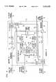
- FIG. 4is a detailed circuit diagram of a control circuit for the pump lasers shown generally in FIG. 2.
- FIG. 1shows an underwater optical transmission system in accordance with this invention.
- the transmission system of FIG. 1transmits optical communication signals back and forth between a first shore terminal 2 and a second shore terminal 3. Those communication signals are sent from the first terminal 2 to the second terminal 3 by way of an optical path 4 and are sent from the second terminal 3 to the first terminal 2 by way of an optical path 5.
- a plurality of repeaterseach of which has been designated with a reference number 10 in FIG. 1, are located in series at predetermined intervals along the optical paths 4 and 5.
- the repeaters 10serve to amplify the optical signals as they travel between terminals 2 and 3.
- the repeaters 10contain optical fiber amplifiers and pump lasers to accomplish their amplification functions.
- a constant current source 6 in terminal 2produces a constant electrical current of predetermined magnitude which is used to power the pump lasers in the repeaters 10.
- the magnitude of the constant currentmay be set or adjusted by a suitable control mechanism in the constant current source 6 so that the average optical power produced by the pump lasers in the repeaters 10 has a desired average magnitude.
- This desired average magnitudeshould be set such that a predetermined bit error rate is produced by the transmission system.
- the average pump laser powermay be set so that the transmission system has its minimum bit error rate or the average pump laser power may be set so that the bit error rate of the transmission system is at some minimum acceptable level and the components of the repeater are not driven excessively.
- the magnitude of the constant currentmay be set to compensate for component aging in the repeaters 10.
- the constant currentis directed to the pump lasers by way of a center conductor 30 which serves to connect the pump lasers of all of the repeaters in series with the constant current source 6.
- the center conductor 30is connected to a voltage source 7 located in the terminal 3. Both the current source 6 and the voltage source 7 are connected to sea ground in the transmission system of FIG. 1.
- FIG. 2is a block diagram of an example of a repeater 10 in accordance with this invention.
- the repeater 10may be one of a number of repeaters in an optical transmission system used to amplify optical communications signals flowing along optical paths between two terminals of the transmission system.
- the optical transmission systemmay be an undersea transmission system in which the terminals are located on shore and one or more repeaters may be located underwater.
- the repeater 10 shown in FIG. 2comprises an optical fiber amplifier 12 which amplifies optical communication signals received on an input fiber 14 either directly from a first terminal of the transmission system or indirectly from one or more other repeaters located in the optical path between the first terminal and the repeater 10.
- the amplified optical communication signalsare directed on an output fiber 16 either directly to a second terminal of the optical transmission system or indirectly to the second terminal via one or more additional repeaters in the optical path between the repeater 10 and the second terminal.
- the repeater 10 in FIG. 2also comprises another optical fiber amplifier 18 which amplifies optical communication signals received on an input fiber 20 either directly from the second terminal of the transmission system or indirectly from one or more other repeaters located in the optical path between the second terminal and the repeater 10.
- the amplified optical communication signalsare directed on an output fiber 22 either directly to the first terminal of the optical transmission system or indirectly to the first terminal via one or more additional repeaters in the optical path between the first terminal and the repeater 10.
- the optical fiber amplifier 12contains a section of specially doped fiber 24 in series with input fiber 14.
- the section of fiber 24can be stimulated by exposing it to optical energy of a predetermined wavelength ⁇ s to amplify the communications signals on input fiber 14.
- the optical fiber amplifier 18contains a similarly doped section of fiber 26 in series with input fiber 20 which amplifies communication signals on fiber 20 in response to stimulation by optical energy of the predetermined wavelength ⁇ s .
- the sections of fiber 24 and 26are doped with a suitable substance such as erbium which provides the amplification capabilities.
- the repeater 10contains a common section 28 which controls the amount of optical stimulation applied to the doped fibers 24 and 26.
- a controlled current source producing dc electrical current having a predetermined constant magnitudeis located in one of the terminals and provides electrical drive power to the fiber amplifiers in the transmission system.
- the current sourcedelivers the constant current to the repeater 10 in FIG. 2, and to every other repeater in the communications system, via a common center conductor 30.
- the center conductor 30serves to connect the common sections of all of the repeaters in the transmission system in series with the current source.
- the line currentis directed to an input line 32 of a control circuit 34 which produces an output signal on line 36.
- the output signal of the control circuit 34controls a regulator 38 which is connected via line 39 to drive a pump laser 40.
- the regulator 38is responsive to the output signal from the control circuit 34 to regulate the optical output power of the laser 40 so that it is substantially proportional to the magnitude of the line current directed to the input of the control circuit 34 on line 30.
- a feedback signal relating to the actual optical power being produced by the pump laser 40is directed on line 42 to another input of the control circuit 34 which then commands the regulator 38 to change the electrical drive power to the pump laser 40 when the optical output power of the laser 40 deviates from a desired level substantially proportional to the magnitude of the line current.
- the optical output power of the pump laser 40is directed on a line 44 to an input of a pump filter 46.
- the output of the pump filter 46is directed to a pump coupler 48, the output of which is sent to a directional wavelength division multiplexer 50.
- the multiplexer 50causes the optical energy produced by the pump laser 40 to be directed into the doped fiber 24 to amplify optical communications signals in that doped fiber 24.
- Amplified communication signals at a carrier frequency ⁇ s from the doped fiber 24are directed by the wavelength division multiplexer 50 through an isolator 52, an ASE noise filter 54, and a coupler 56 to the output fiber 16.
- the common section 28also controls the level of optical stimulation applied to the doped fiber 26.
- the control circuit 34produces an output signal on line 58 which causes a regulator 60 to control electrical drive power on line 62 to be controlled so that a pump laser 64 produces optical output power having a desired magnitude substantially proportional to the magnitude of the line current introduced to the common section on line 30.
- a feedback signalis produced on line 66 relating to the magnitude of optical power actually being produced by the pump laser 64.
- the control circuit 34is responsive to the magnitude of the line current on line 32 and the feedback signal on line 66 to cause the regulator 60 to change the drive power to the pump laser 64 when the optical output power of the laser 64 deviates from a desired magnitude proportional to the magnitude of the line current.
- the optical output power of the pump laser 64 on line 68is delivered to a pump filter 70 and thence to the pump coupler 48 and a wavelength division multiplexer 72.
- the multiplexer 72causes optical energy at the frequency of the pump laser to be directed to the doped fiber 26 to stimulate that fiber and amplify communication signals introduced to the fiber 26 via input fiber 20.
- the amplified communications signals at the carrier frequency ⁇ s from the fiber 26are routed by the wavelength division multiplexer 72 through an isolator 74, an ASE noise filter 76, and a coupler 78 to the output fiber 22.
- a Zener diode 80provides overvoltage protection for the control circuit 34 and is connected between lines 32 and 82 in FIG. 2. After line current has passed through the control circuit 34, it is directed on a line 82 out of the control circuit and on toward the common section of the next repeater in the transmission system as illustrated by arrow 82 drawn on conductor 30 in FIG. 2.
- a portion of the signal flowing in fiber 16 traveling in a direction from the first terminal to the second terminalmay be fed back to the first terminal by means of the coupler 56, an attenuator 57, an optical path 59, the coupler 78, and the fiber 22 for test purposes in accordance with the principles of application Ser. No. 07/753,582, filed Sep. 3, 1991.
- a portion of the signal flowing in fiber 22 traveling in a direction from the second terminal to the first terminalmay be fed back to the second terminal by means of the coupler 78, an attenuator 79, an optical path 81, and the coupler 56 in accordance with the principles of this application.
- the optical outputs of the pump lasers 40 and 64are directed to the fibers 24 and 26 by means of the coupler 48 so that either one of the pump lasers may be used to power both fibers 24 and 26 in a situation where one of the pump lasers has failed in accordance with the principles of application Ser. No. 07/758,665, filed Sep. 12, 1991.
- FIG. 2shows only one pair of fiber amplifiers for both directions of transmission through the repeater 10, it is possible in some embodiments of the invention to have more than one series connected pair of amplifiers within a single repeater.
- FIG. 3shows an example of such multiple stages of amplification in a single repeater.
- FIG. 3shows a repeater housing 84, which may be constructed of beryllium copper, connected to sea ground 86 in an underwater transmission system.
- the amplifier pairs 90, 92, 94, and 96are located in a cylindrical housing within the repeater housing 84.
- Line currentis introduced into the repeater of FIG. 3 on a center conductor 88.
- Amplifier pairs 90, 92, 94, and 96are connected in series with each other and receive the line current on line 88.
- Line currentpasses through each of the amplifier pairs 90, 92, 94, and 96 and is directed out of the repeater on a line 98.
- Each of the amplifier pairs 90, 92, 94, and 96contains a fiber amplifier stage like the fiber amplifier 12 in FIG. 2 for one direction of transmission and a fiber amplifier stage like the fiber amplifier 18 in FIG. 2 for a second direction of transmission.
- Each of the amplifiers in the amplifier pairs 90, 92, 94, and 96may be controlled in a fashion like the amplifiers 12 and 18 are controlled, namely, the amplifiers may be controlled so that the optical output power produced by pump lasers is substantially proportional to the magnitude of the line current on line 88.
- the power circuitsare connected via a single resistor to the chassis and there are power connections between the amplifiers. The resistor prevents the buildup of static charge between the power circuits and the inner cylinder.
- FIG. 4shows in more detail an example of electronic circuitry which may be used to implement the function of the common section 28 of the repeater 10 shown in FIG. 2.
- the circuitry of FIG. 4may also be used to implement a corresponding common section for the repeater shown in FIG. 3.
- the electronic circuitry of FIG. 4receives line current of a predetermined constant magnitude on a conductor 30 which is produced by a controllable constant current source is one of the terminals of the transmission system.
- the constant current on line 30is delivered to each series connected repeater in the transmission system for purposes of powering the pump lasers and controlling the magnitude of the optical power produced by those lasers.
- Two pump lasers 40 and 64 in one of the repeatersare connected in series with the conductor 30 and receive a part or all of the line current to produce optical pump power injected into the fibers 24 and 26 for amplifying optical communications signals.
- the pump lasers 40 and 64contain a laser diode 102 and a laser diode 104, respectively.
- the amount of the line current which flows through the pump lasers, and the amount of optical power they produce,is controlled by a feedback circuit which controls the drive current through the pump lasers as a function of a reference current signal proportional to the magnitude of the line current and a feedback signal proportional to the actual magnitude of the optical power produced by the pump lasers 40 and 64.
- a reference current proportional to the line current in conductor 30is produced in line 106 by the action of a current reference circuit comprising three transistors 108, 110, and 112 connected together in a current mirror configuration.
- the magnitude of the reference currentrepresents the optical power desired from the pump laser 40.
- the laser 40includes a means for focusing a fixed portion of the optical output from the backface of the laser diode 102 onto a monitor diode 114.
- the monitor diode 114produces a feedback dc current signal proportional to the magnitude of the optical power produced by the pump laser 40.
- the reference current signal and the feedback current signalare connected together at a summing junction 116, thus creating an error signal on line 117 representing, the difference in magnitude of the desired and actual power outputs of the pump laser 40.
- This error signalis connected to a pair of series connected control amplifiers 118 and 120, the output which is connected to a shunt regulator comprising a pair of transistors 122 and 124 connected in a Darlington configuration.
- the error signalafter amplification by the amplifiers 118 and 120, drives the shunt regulator such that the current through the shunt regulator is proportional to the amount by which the current through the backface monitor diode exceeds the current produced by the aforementioned current reference circuit.
- the drive current to the pump laser 40thus is regulated to be substantially equal to the magnitude of the reference current and substantially proportional to the line current directed to the repeaters on conductor 30.
- the pump power to laser 40thus can easily be controlled from the terminals of the communication system.
- the current reference circuitproduces a reference current on line 124 proportional to the line current is conductor 30.
- the magnitude of this reference currentrepresents the optical power desired from the pump laser 64.
- the laser 64includes a means for focusing a portion of the optical output from the backface of the laser diode 104 onto a monitor diode 126.
- the monitor diode 126produces a feedback DC current signal proportional to the magnitude of the optical power produced by the pump laser 64.
- the reference current signal on line 124 and the feedback current signal from the monitor diode 126are connected together at a summing junction 128, thus creating an error signal on line 129 representing the difference in magnitude of the desired and actual power outputs of the pump laser 64.
- This error signalis connected to a pair of series connected control amplifiers 130 and 132, the output of which is connected to a shunt regulator comprising a pair of transistor 134 and 136 connected in a Darlington configuration.
- the error signalafter amplification by the amplifiers 130 and 132, drives the shunt regulator such that the current through the shunt regulator is proportional to the amount by which the current through the backface monitor diode 126 exceeds the reference current produced by the current reference circuit.
- the drive current to the pump laser 64thus is regulated to be equal to the magnitude of the reference current and substantially proportional to the line current directed to the repeater on conductor 30.
- the power to the pump laser 64can be easily controlled from the terminals of the communications system by appropriately setting the level of the current on conductor 30.
- the pump power in any of the other repeaters located between the terminals of the transmission systemcan be similarly controlled by an appropriate setting of the magnitude of the dc current on conductor 30.
- the average pump powerwhich will be determined by the set magnitude of the line current on conductor 30.
- the circuit of FIG. 4also includes protective diodes 138, 140, 142, and 144 which together with the Darlington connected shunt regulator limits the maximum pump laser voltages to about 3 volts and provides a current path in the case of an open circuit pump failure.
- the circuit of FIG. 4also contains the aforementioned Zener diode 80 which is normally nonconducting and which protects the controller and pumps from excess currents, for example, from current surges resulting from cable faults.
- the circuit of FIG. 4also includes a low frequency bypass circuit composed of amplifier 146, amplifier 148, and transistor 150, alo with certain passive components which determine the gain and frequency response of the low frequency bypass circuit. Examples of suitable circuit values for the passive components are given in FIG. 4.
- the purpose of this circuitis to provide a low impedance path for AC currents having frequencies in a predetermined range, for example, in the range of 4-30 Hz. AC currents like these may be superimposed on the DC line current in conductor 30 to facilitate the location of an undersea cable from the surface of the water during maintenance and repair operations.
- the circuitis basically an active shunt filter which shunts the AC component of the current on conductor 30 around the pump power control circuitry. As described above, the remainder of the current on conductor 30 flows through the two pump lasers 40 and 64, their controllers, and the reference circuit.
- the bit error rate or the signal-to-noise ratio of the systemcan be measured as a function of line current on conductor 30.
- the magnitude of the line currentmay then be set so that the bit error rate or signal-to-noise ratio is maximized or otherwise set to some desired level, for example, to some minimum acceptable level to perhaps extend the life of the components used in the repeaters.
Landscapes
- Physics & Mathematics (AREA)
- Electromagnetism (AREA)
- Engineering & Computer Science (AREA)
- Computer Networks & Wireless Communication (AREA)
- Signal Processing (AREA)
- Optical Communication System (AREA)
- Lasers (AREA)
- Cable Transmission Systems, Equalization Of Radio And Reduction Of Echo (AREA)
Abstract
Description
This application relates to optical transmission systems. More particularly, this application relates to repeatered optical transmission systems involving optical fiber amplification of communication signals.
Long distance optical transmission systems generally require that the optical signals flowing in those transmission systems be amplified at periodic intervals along the length of the transmission system. The optical signals may be amplified by a number of repeaters located along the length of the transmission system. Repeatered optical transmission systems generally fall into two broad categories, those using electro-optical regenerators and those using optical fiber amplification. Electro-optical regenerators are not very desirable because they contain a complex array of parts, including a receiver which converts weak optical pulses into electrical pulses which are then amplified, reshaped, retimed, and converted back into light pulses for continued transmission through the system. These complexities can be avoided because recent advances in fiber and optical amplifier technology make possible the linear amplification of light pulses without such electro-optical conversion. Because of their relative simplicity and excellent gain characteristics, optical fiber amplifiers are highly desirable, especially in repeatered undersea systems.
It is crucial that the gain of the fiber amplifiers be carefully controlled for low bit error rates in the transmission system and long service life of the components used in the repeaters. The gain in a fiber amplifier results from interactions, in a specially doped length of fiber, between signal photons having a wavelength λs with photons produced by a pump laser having a wavelength λp, where λs is greater than λp. The dopant in the fiber, typically erbium, absorbs the power from the pump laser at wavelength λp and emits optical power under such stimulation at a wavelength λs. One of the parameters which determines the gain of a fiber amplifier and the output power is the output power of the pump laser which stimulates the doped fiber. Specifically, both the gain and output power increase with increasing pump laser power. The gain and output power should be high enough so that the signal level is significantly above the noise floor. However, the output power cannot be too high or the effect of fiber non-linearities being to intrude.
The performance of a fiber amplifier based transmission system is limited by the presence of amplified spontaneous emission (ASE) noise generated by the amplifier and by the effect of chromatic dispersion and nonlinearities in the transmission fibers. At low signal levels, inadequate signal-to-noise ratio is a concern. At high signal levels, non-linearities are a similar concern. The dominant nonlinear effect is the Kerr effect which causes the refractive index of the fiber to change with light power density through the fiber. This nonlinearity spreads the signal spectrum and mixes it with the ASE noise spectrum. The chromatic dispersion phenomenon then causes communication pulses to spread in time resulting in intersymbol interference. Under both low signal conditions and high signal conditions, therefore, serious signal degradation may result. In any transmission system containing fiber amplifiers, there is a particular level of pump laser power which produces minimum signal degradation and, hence, the lowest bit error rate by insuring optimum signal-to-noise ratio and minimizing the effects of nonlinearities. At lower pump laser power levels, the communications signal level decreases and the level of the ASE noise may make it difficult to differentiate the signals from the noise. At higher power levels, the nonlinear mixing of communication signals and ASE noise becomes important. Therefore, there is an urgent need for economically and effectively controlling the optical output power of each of the pump lasers in an optical fiber amplifier based transmission system.
It is extremely difficult to predict in advance the optimum pump laser power needed in each repeater. It has been found, however, that it is not necessary to individually control each pump laser independently. Because there are only small variations among fiber amplifiers, it suffices to control the average power of all the pump lasers in the transmission system. The average pump laser power may be conveniently controlled from the terminals of the transmission system so that the system has the lowest bit error rate or so that the pump laser power is at a minimum level which will result in a certain minimum bit error rate. The latter approach results in a lower pump aging rate, a longer system life, and lower maintenance costs.
In one example of this invention, the requirements of economically and efficiently controlling the optical output power of the pump lasers in optical fiber amplifier based repeaters are met by an apparatus which regulates the optical power produced by the pump lasers in accordance with a controlled constant dc line current produced at the terminals of the optical transmission system. Each repeater contains an electronic regulator responsive to the magnitude of the line current and the optical power produced by a pump laser to control the output power produced by the laser. The pump laser stimulates a specially doped section of fiber carrying communication signals in the transmission system.
FIG. 1 shows an example of an optical transmission system in accordance with this invention.
FIG. 2 is a schematic diagram of one example of an optical fiber amplifier based repeater useful in an optical transmission system in accordance with this invention.
FIG. 3 shows another example of an optical fiber amplifier based repeater useful in an optical transmission system in accordance with this invention.
FIG. 4 is a detailed circuit diagram of a control circuit for the pump lasers shown generally in FIG. 2.
FIG. 1 shows an underwater optical transmission system in accordance with this invention. The transmission system of FIG. 1 transmits optical communication signals back and forth between afirst shore terminal 2 and asecond shore terminal 3. Those communication signals are sent from thefirst terminal 2 to thesecond terminal 3 by way of an optical path 4 and are sent from thesecond terminal 3 to thefirst terminal 2 by way of an optical path 5. A plurality of repeaters, each of which has been designated with areference number 10 in FIG. 1, are located in series at predetermined intervals along the optical paths 4 and 5. Therepeaters 10 serve to amplify the optical signals as they travel betweenterminals repeaters 10 contain optical fiber amplifiers and pump lasers to accomplish their amplification functions. A constantcurrent source 6 interminal 2 produces a constant electrical current of predetermined magnitude which is used to power the pump lasers in therepeaters 10. The magnitude of the constant current may be set or adjusted by a suitable control mechanism in the constantcurrent source 6 so that the average optical power produced by the pump lasers in therepeaters 10 has a desired average magnitude. This desired average magnitude should be set such that a predetermined bit error rate is produced by the transmission system. For example, the average pump laser power may be set so that the transmission system has its minimum bit error rate or the average pump laser power may be set so that the bit error rate of the transmission system is at some minimum acceptable level and the components of the repeater are not driven excessively. The magnitude of the constant current may be set to compensate for component aging in therepeaters 10. The constant current is directed to the pump lasers by way of acenter conductor 30 which serves to connect the pump lasers of all of the repeaters in series with the constantcurrent source 6. Thecenter conductor 30 is connected to avoltage source 7 located in theterminal 3. Both thecurrent source 6 and thevoltage source 7 are connected to sea ground in the transmission system of FIG. 1.
FIG. 2 is a block diagram of an example of arepeater 10 in accordance with this invention. Therepeater 10 may be one of a number of repeaters in an optical transmission system used to amplify optical communications signals flowing along optical paths between two terminals of the transmission system. The optical transmission system may be an undersea transmission system in which the terminals are located on shore and one or more repeaters may be located underwater. Therepeater 10 shown in FIG. 2 comprises anoptical fiber amplifier 12 which amplifies optical communication signals received on aninput fiber 14 either directly from a first terminal of the transmission system or indirectly from one or more other repeaters located in the optical path between the first terminal and therepeater 10. The amplified optical communication signals are directed on anoutput fiber 16 either directly to a second terminal of the optical transmission system or indirectly to the second terminal via one or more additional repeaters in the optical path between therepeater 10 and the second terminal. Therepeater 10 in FIG. 2 also comprises anotheroptical fiber amplifier 18 which amplifies optical communication signals received on aninput fiber 20 either directly from the second terminal of the transmission system or indirectly from one or more other repeaters located in the optical path between the second terminal and therepeater 10. The amplified optical communication signals are directed on anoutput fiber 22 either directly to the first terminal of the optical transmission system or indirectly to the first terminal via one or more additional repeaters in the optical path between the first terminal and therepeater 10.
Theoptical fiber amplifier 12 contains a section of specially dopedfiber 24 in series withinput fiber 14. The section offiber 24 can be stimulated by exposing it to optical energy of a predetermined wavelength λs to amplify the communications signals oninput fiber 14. Theoptical fiber amplifier 18 contains a similarly doped section offiber 26 in series withinput fiber 20 which amplifies communication signals onfiber 20 in response to stimulation by optical energy of the predetermined wavelength λs. Typically, the sections offiber
Therepeater 10 contains acommon section 28 which controls the amount of optical stimulation applied to the dopedfibers repeater 10 in FIG. 2, and to every other repeater in the communications system, via acommon center conductor 30. Thecenter conductor 30 serves to connect the common sections of all of the repeaters in the transmission system in series with the current source. The line current is directed to aninput line 32 of acontrol circuit 34 which produces an output signal online 36. The output signal of thecontrol circuit 34 controls aregulator 38 which is connected vialine 39 to drive apump laser 40. Theregulator 38 is responsive to the output signal from thecontrol circuit 34 to regulate the optical output power of thelaser 40 so that it is substantially proportional to the magnitude of the line current directed to the input of thecontrol circuit 34 online 30. A feedback signal relating to the actual optical power being produced by thepump laser 40 is directed online 42 to another input of thecontrol circuit 34 which then commands theregulator 38 to change the electrical drive power to thepump laser 40 when the optical output power of thelaser 40 deviates from a desired level substantially proportional to the magnitude of the line current. The optical output power of thepump laser 40 is directed on aline 44 to an input of apump filter 46. The output of thepump filter 46 is directed to apump coupler 48, the output of which is sent to a directionalwavelength division multiplexer 50. Themultiplexer 50 causes the optical energy produced by thepump laser 40 to be directed into the dopedfiber 24 to amplify optical communications signals in that dopedfiber 24. Amplified communication signals at a carrier frequency λs from the dopedfiber 24 are directed by thewavelength division multiplexer 50 through anisolator 52, anASE noise filter 54, and acoupler 56 to theoutput fiber 16.
Thecommon section 28 also controls the level of optical stimulation applied to the dopedfiber 26. Thecontrol circuit 34 produces an output signal online 58 which causes aregulator 60 to control electrical drive power on line 62 to be controlled so that apump laser 64 produces optical output power having a desired magnitude substantially proportional to the magnitude of the line current introduced to the common section online 30. A feedback signal is produced online 66 relating to the magnitude of optical power actually being produced by thepump laser 64. Thecontrol circuit 34 is responsive to the magnitude of the line current online 32 and the feedback signal online 66 to cause theregulator 60 to change the drive power to thepump laser 64 when the optical output power of thelaser 64 deviates from a desired magnitude proportional to the magnitude of the line current. The optical output power of thepump laser 64 online 68 is delivered to apump filter 70 and thence to thepump coupler 48 and awavelength division multiplexer 72. Themultiplexer 72 causes optical energy at the frequency of the pump laser to be directed to the dopedfiber 26 to stimulate that fiber and amplify communication signals introduced to thefiber 26 viainput fiber 20. The amplified communications signals at the carrier frequency λs from thefiber 26 are routed by thewavelength division multiplexer 72 through anisolator 74, anASE noise filter 76, and acoupler 78 to theoutput fiber 22.
AZener diode 80 provides overvoltage protection for thecontrol circuit 34 and is connected betweenlines control circuit 34, it is directed on aline 82 out of the control circuit and on toward the common section of the next repeater in the transmission system as illustrated byarrow 82 drawn onconductor 30 in FIG. 2.
A portion of the signal flowing infiber 16 traveling in a direction from the first terminal to the second terminal may be fed back to the first terminal by means of thecoupler 56, anattenuator 57, anoptical path 59, thecoupler 78, and thefiber 22 for test purposes in accordance with the principles of application Ser. No. 07/753,582, filed Sep. 3, 1991. Similarly, a portion of the signal flowing infiber 22 traveling in a direction from the second terminal to the first terminal may be fed back to the second terminal by means of thecoupler 78, anattenuator 79, anoptical path 81, and thecoupler 56 in accordance with the principles of this application. The optical outputs of thepump lasers fibers coupler 48 so that either one of the pump lasers may be used to power bothfibers
Although FIG. 2 shows only one pair of fiber amplifiers for both directions of transmission through therepeater 10, it is possible in some embodiments of the invention to have more than one series connected pair of amplifiers within a single repeater. FIG. 3 shows an example of such multiple stages of amplification in a single repeater. FIG. 3 shows arepeater housing 84, which may be constructed of beryllium copper, connected tosea ground 86 in an underwater transmission system. The amplifier pairs 90, 92, 94, and 96 are located in a cylindrical housing within therepeater housing 84. Line current is introduced into the repeater of FIG. 3 on a center conductor 88. Amplifier pairs 90, 92, 94, and 96 are connected in series with each other and receive the line current on line 88. Line current passes through each of the amplifier pairs 90, 92, 94, and 96 and is directed out of the repeater on a line 98. Each of the amplifier pairs 90, 92, 94, and 96 contains a fiber amplifier stage like thefiber amplifier 12 in FIG. 2 for one direction of transmission and a fiber amplifier stage like thefiber amplifier 18 in FIG. 2 for a second direction of transmission. Each of the amplifiers in the amplifier pairs 90, 92, 94, and 96 may be controlled in a fashion like theamplifiers
FIG. 4 shows in more detail an example of electronic circuitry which may be used to implement the function of thecommon section 28 of therepeater 10 shown in FIG. 2. The circuitry of FIG. 4 may also be used to implement a corresponding common section for the repeater shown in FIG. 3. The electronic circuitry of FIG. 4 receives line current of a predetermined constant magnitude on aconductor 30 which is produced by a controllable constant current source is one of the terminals of the transmission system. The constant current online 30 is delivered to each series connected repeater in the transmission system for purposes of powering the pump lasers and controlling the magnitude of the optical power produced by those lasers. Twopump lasers conductor 30 and receive a part or all of the line current to produce optical pump power injected into thefibers pump lasers laser diode 102 and a laser diode 104, respectively. The amount of the line current which flows through the pump lasers, and the amount of optical power they produce, is controlled by a feedback circuit which controls the drive current through the pump lasers as a function of a reference current signal proportional to the magnitude of the line current and a feedback signal proportional to the actual magnitude of the optical power produced by thepump lasers
A reference current proportional to the line current inconductor 30 is produced inline 106 by the action of a current reference circuit comprising threetransistors pump laser 40. Thelaser 40 includes a means for focusing a fixed portion of the optical output from the backface of thelaser diode 102 onto amonitor diode 114. Themonitor diode 114 produces a feedback dc current signal proportional to the magnitude of the optical power produced by thepump laser 40. The reference current signal and the feedback current signal are connected together at a summingjunction 116, thus creating an error signal online 117 representing, the difference in magnitude of the desired and actual power outputs of thepump laser 40. This error signal is connected to a pair of series connectedcontrol amplifiers transistors amplifiers pump laser 40 thus is regulated to be substantially equal to the magnitude of the reference current and substantially proportional to the line current directed to the repeaters onconductor 30. The pump power tolaser 40 thus can easily be controlled from the terminals of the communication system.
Similarly, the current reference circuit produces a reference current online 124 proportional to the line current isconductor 30. The magnitude of this reference current represents the optical power desired from thepump laser 64. Thelaser 64 includes a means for focusing a portion of the optical output from the backface of the laser diode 104 onto amonitor diode 126. Themonitor diode 126 produces a feedback DC current signal proportional to the magnitude of the optical power produced by thepump laser 64. The reference current signal online 124 and the feedback current signal from themonitor diode 126 are connected together at a summingjunction 128, thus creating an error signal online 129 representing the difference in magnitude of the desired and actual power outputs of thepump laser 64. This error signal is connected to a pair of series connectedcontrol amplifiers transistor amplifiers backface monitor diode 126 exceeds the reference current produced by the current reference circuit. The drive current to thepump laser 64 thus is regulated to be equal to the magnitude of the reference current and substantially proportional to the line current directed to the repeater onconductor 30. As in the case of thepump laser 40, the power to thepump laser 64 can be easily controlled from the terminals of the communications system by appropriately setting the level of the current onconductor 30.
Likewise, the pump power in any of the other repeaters located between the terminals of the transmission system can be similarly controlled by an appropriate setting of the magnitude of the dc current onconductor 30. In systems having more than one repeater in series with theconductor 30, it will be the average pump power which will be determined by the set magnitude of the line current onconductor 30.
The circuit of FIG. 4 also includesprotective diodes aforementioned Zener diode 80 which is normally nonconducting and which protects the controller and pumps from excess currents, for example, from current surges resulting from cable faults. The circuit of FIG. 4 also includes a low frequency bypass circuit composed ofamplifier 146,amplifier 148, andtransistor 150, alo with certain passive components which determine the gain and frequency response of the low frequency bypass circuit. Examples of suitable circuit values for the passive components are given in FIG. 4. The purpose of this circuit is to provide a low impedance path for AC currents having frequencies in a predetermined range, for example, in the range of 4-30 Hz. AC currents like these may be superimposed on the DC line current inconductor 30 to facilitate the location of an undersea cable from the surface of the water during maintenance and repair operations. The circuit is basically an active shunt filter which shunts the AC component of the current onconductor 30 around the pump power control circuitry. As described above, the remainder of the current onconductor 30 flows through the twopump lasers
To optimize a transmission system using one or more repeaters in accordance with this invention, the bit error rate or the signal-to-noise ratio of the system can be measured as a function of line current onconductor 30. The magnitude of the line current may then be set so that the bit error rate or signal-to-noise ratio is maximized or otherwise set to some desired level, for example, to some minimum acceptable level to perhaps extend the life of the components used in the repeaters.
Claims (4)
1. An optical transmission system, comprising:
a controllable line current source for producing a substantially constant current of a predetermined magnitude;
an optical fiber amplifier which amplifies optical communications signals carried by the transmission system;
a circuit responsive to the magnitude of the line current comprising a pump laser for controlling the gain of the fiber amplifier in substantial proportion to the predetermined magnitude of the constant current in which the pump laser produces an optical power output which is directed to a section of doped fiber in the optical fiber amplifier;
the circuit controlling the gain of the fiber amplifier further comprising:
a current reference circuit which produces a current signal having a magnitude proportional to the magnitude of the constant current;
a circuit for producing a current signal having a magnitude representing the magnitude of the optical power output produced by the pump laser; and
a regulator for controlling the optical power output of the laser in accordance with any difference between the magnitude of the current signals produced by the current reference circuit and the circuit for producing a current signal representing the magnitude of the optical power output of the pump laser.
2. The transmission system of claim 1, in which the circuit for producing a current signal having a magnitude representing the magnitude of the optical power output of the pump laser comprises a monitor diode responsive to the optical power output of the pump laser.
3. The transmission system of claim 1, further comprising:
a summing junction producing an output signal related to the difference between the magnitudes of the current reference signal and the current signal representing the magnitude of the optical power output of the pump laser;
an amplifier for increasing the magnitude of the output signal from the summing junction;
a shunt regulator responsive to the increased magnitude output signal from the summing junction which controls drive current to the pump laser.
4. An optical underwater transmission system, comprising:
first and second shore terminals;
a first optical path for carrying optical communications signals from the first shore terminal to the second shore terminal;
a second optical path for carrying optical communications signals from the second shore terminal to the first shore terminal;
a plurality of repeaters spaced at predetermined distances along the first and second optical paths in which each repeater includes a fiber amplifier for amplifying the optical communications signals in those paths;
a constant current source in one of the first and second shore terminals for providing substantially constant electrical current of a predetermined magnitude for the repeaters;
a pump laser in each of the repeaters for producing optical power which causes the fiber amplifiers to amplify the optical communications signals;
a means for controlling the average optical power produced by the pump lasers in the plurality of repeaters in response to the magnitude of the constant current;
the means for controlling the average optical power comprising
a regulator for causing some or all of the constant current to flow through the pump laser; and
a circuit responsive to the magnitude of the constant current and the optical power output of the pump laser for controlling the regulator to cause an amount of the constant current to flow through the pump laser such that the optical power produced by the pump laser is a desired amount proportional to the magnitude of the line current.
Priority Applications (4)
| Application Number | Priority Date | Filing Date | Title |
|---|---|---|---|
| US07/926,629US5343320A (en) | 1992-08-03 | 1992-08-03 | Pump laser control circuit for an optical transmission system |
| EP93305781AEP0582406B1 (en) | 1992-08-03 | 1993-07-22 | Pump laser control circuit for an optical transmission system |
| DE69326861TDE69326861T2 (en) | 1992-08-03 | 1993-07-22 | Pump laser control circuit for an optical transmission system |
| JP19151993AJP3478853B2 (en) | 1992-08-03 | 1993-08-03 | Pump laser control circuit for optical transmission system |
Applications Claiming Priority (1)
| Application Number | Priority Date | Filing Date | Title |
|---|---|---|---|
| US07/926,629US5343320A (en) | 1992-08-03 | 1992-08-03 | Pump laser control circuit for an optical transmission system |
Publications (1)
| Publication Number | Publication Date |
|---|---|
| US5343320Atrue US5343320A (en) | 1994-08-30 |
Family
ID=25453478
Family Applications (1)
| Application Number | Title | Priority Date | Filing Date |
|---|---|---|---|
| US07/926,629Expired - LifetimeUS5343320A (en) | 1992-08-03 | 1992-08-03 | Pump laser control circuit for an optical transmission system |
Country Status (4)
| Country | Link |
|---|---|
| US (1) | US5343320A (en) |
| EP (1) | EP0582406B1 (en) |
| JP (1) | JP3478853B2 (en) |
| DE (1) | DE69326861T2 (en) |
Cited By (62)
| Publication number | Priority date | Publication date | Assignee | Title |
|---|---|---|---|---|
| US5467219A (en)* | 1993-04-13 | 1995-11-14 | Nec Corporation | Control device for an optical amplifier |
| US5510931A (en)* | 1989-08-31 | 1996-04-23 | Fujitsu Limited | Optical amplifier and optical communication system with optical amplifier using pumping right beam |
| US5524144A (en)* | 1992-09-14 | 1996-06-04 | Kabushiki Kaisha Toshiba | Optical transmission apparatus |
| US5561552A (en)* | 1993-04-13 | 1996-10-01 | Nec Corporation | Optical fiber amplifier unit and method for supplying excited light thereof |
| US5570227A (en)* | 1994-03-02 | 1996-10-29 | Fujitsu Limited | Method and apparatus for preventing occurrence of surge light in optical amplifier/transmitter apparatus |
| US5581397A (en)* | 1993-12-17 | 1996-12-03 | Fujitsu Limited | Optical-fiber amplifier |
| DE19702891A1 (en)* | 1996-01-29 | 1997-07-31 | Samsung Electronics Co Ltd | Optical fiber amplifier |
| US5706126A (en)* | 1995-09-14 | 1998-01-06 | Nec Corporation | Optical amplifier |
| US5710660A (en)* | 1995-03-08 | 1998-01-20 | Kokusai Denshin Denwa Co., Ltd. | Gain-controllable optical amplifier and optical gain-control method |
| US5801878A (en)* | 1996-04-18 | 1998-09-01 | Alcatel Submarine Networks | Circuit having two optical amplifiers, in particular for a repeater in an undersea telecommunications system |
| US5808786A (en)* | 1995-12-14 | 1998-09-15 | Nec Corporation | Optical fiber amplifying device and method therefor |
| US5812289A (en)* | 1992-04-08 | 1998-09-22 | Hitachi, Ltd. | Optical repeater and optical transmitter |
| US6134032A (en)* | 1999-04-02 | 2000-10-17 | Tyco Submarine Systems Ltd. | Method and apparatus for automatically identifying system faults in an optical communications system from repeater loop gain signatures |
| US6188510B1 (en)* | 1998-02-20 | 2001-02-13 | Kdd Corporation | Optical amplifying transmission system and optical amplifying repeater |
| US6266169B1 (en) | 1992-04-08 | 2001-07-24 | Hitachi, Ltd. | Optical transmission equipment which transmits an amplified optical data signal and an optical surveillance signal |
| US6366381B1 (en) | 1997-08-08 | 2002-04-02 | Tycom (Us) Inc. | Remote monitoring of an optical transmission system using line monitoring signals |
| EP1206057A1 (en)* | 2000-11-14 | 2002-05-15 | Siemens Aktiengesellschaft | Method of amplification of optical signals |
| US6674566B2 (en)* | 2000-10-05 | 2004-01-06 | Nortel Networks Limited | Raman amplification |
| US20040032645A1 (en)* | 1999-10-29 | 2004-02-19 | Fujitsu Limited | Optical transmitting apparatus and optical repeating apparatus |
| US20040036959A1 (en)* | 2002-08-20 | 2004-02-26 | Evangelides Stephen G. | Optical transmission system employing erbium-doped optical amplifiers and Raman amplifiers |
| US6738584B1 (en)* | 1998-07-08 | 2004-05-18 | Fujitsu Ltd. | Method for optical fiber communication, and terminal device and system for use in carrying out the method |
| US20040212875A1 (en)* | 2002-01-30 | 2004-10-28 | Jinghui Li | Integrated optical dual amplifier |
| US7075712B2 (en) | 2002-05-30 | 2006-07-11 | Fujitsu Limited | Combining and distributing amplifiers for optical network and method |
| US7085496B2 (en) | 2002-05-30 | 2006-08-01 | Fujitsu Limited | Passive add/drop amplifier for optical networks and method |
| US20070076595A1 (en)* | 2005-09-30 | 2007-04-05 | Samsung Electronics Co., Ltd. | Power line communication method and apparatus |
| US20070115539A1 (en)* | 2005-11-21 | 2007-05-24 | Alcatel | Optical transmission system and optical filter assembly for submarine applications |
| US20080232808A1 (en)* | 2007-03-20 | 2008-09-25 | Fujitsu Limited | Optical waveform controlling apparatus |
| US20080232305A1 (en)* | 2006-12-19 | 2008-09-25 | Yair Oren | Distributed Antenna System for MIMO Technologies |
| US20110200325A1 (en)* | 2010-02-15 | 2011-08-18 | Andrey Kobyakov | Dynamic Cell Bonding (DCB) for Radio-over-Fiber (RoF)-Based Networks and Communication Systems and Related Methods |
| US8644844B2 (en) | 2007-12-20 | 2014-02-04 | Corning Mobileaccess Ltd. | Extending outdoor location based services and applications into enclosed areas |
| US9112611B2 (en) | 2009-02-03 | 2015-08-18 | Corning Optical Communications LLC | Optical fiber-based distributed antenna systems, components, and related methods for calibration thereof |
| US9178635B2 (en) | 2014-01-03 | 2015-11-03 | Corning Optical Communications Wireless Ltd | Separation of communication signal sub-bands in distributed antenna systems (DASs) to reduce interference |
| US9184843B2 (en) | 2011-04-29 | 2015-11-10 | Corning Optical Communications LLC | Determining propagation delay of communications in distributed antenna systems, and related components, systems, and methods |
| US9219879B2 (en) | 2009-11-13 | 2015-12-22 | Corning Optical Communications LLC | Radio-over-fiber (ROF) system for protocol-independent wired and/or wireless communication |
| US9240835B2 (en) | 2011-04-29 | 2016-01-19 | Corning Optical Communications LLC | Systems, methods, and devices for increasing radio frequency (RF) power in distributed antenna systems |
| US9247543B2 (en) | 2013-07-23 | 2016-01-26 | Corning Optical Communications Wireless Ltd | Monitoring non-supported wireless spectrum within coverage areas of distributed antenna systems (DASs) |
| US9258052B2 (en) | 2012-03-30 | 2016-02-09 | Corning Optical Communications LLC | Reducing location-dependent interference in distributed antenna systems operating in multiple-input, multiple-output (MIMO) configuration, and related components, systems, and methods |
| US9357551B2 (en) | 2014-05-30 | 2016-05-31 | Corning Optical Communications Wireless Ltd | Systems and methods for simultaneous sampling of serial digital data streams from multiple analog-to-digital converters (ADCS), including in distributed antenna systems |
| US9385810B2 (en) | 2013-09-30 | 2016-07-05 | Corning Optical Communications Wireless Ltd | Connection mapping in distributed communication systems |
| US9420542B2 (en) | 2014-09-25 | 2016-08-16 | Corning Optical Communications Wireless Ltd | System-wide uplink band gain control in a distributed antenna system (DAS), based on per band gain control of remote uplink paths in remote units |
| US9455784B2 (en) | 2012-10-31 | 2016-09-27 | Corning Optical Communications Wireless Ltd | Deployable wireless infrastructures and methods of deploying wireless infrastructures |
| US9525472B2 (en) | 2014-07-30 | 2016-12-20 | Corning Incorporated | Reducing location-dependent destructive interference in distributed antenna systems (DASS) operating in multiple-input, multiple-output (MIMO) configuration, and related components, systems, and methods |
| US9531452B2 (en) | 2012-11-29 | 2016-12-27 | Corning Optical Communications LLC | Hybrid intra-cell / inter-cell remote unit antenna bonding in multiple-input, multiple-output (MIMO) distributed antenna systems (DASs) |
| US9602210B2 (en) | 2014-09-24 | 2017-03-21 | Corning Optical Communications Wireless Ltd | Flexible head-end chassis supporting automatic identification and interconnection of radio interface modules and optical interface modules in an optical fiber-based distributed antenna system (DAS) |
| US9621293B2 (en) | 2012-08-07 | 2017-04-11 | Corning Optical Communications Wireless Ltd | Distribution of time-division multiplexed (TDM) management services in a distributed antenna system, and related components, systems, and methods |
| US9647758B2 (en) | 2012-11-30 | 2017-05-09 | Corning Optical Communications Wireless Ltd | Cabling connectivity monitoring and verification |
| US9661781B2 (en) | 2013-07-31 | 2017-05-23 | Corning Optical Communications Wireless Ltd | Remote units for distributed communication systems and related installation methods and apparatuses |
| US9673904B2 (en) | 2009-02-03 | 2017-06-06 | Corning Optical Communications LLC | Optical fiber-based distributed antenna systems, components, and related methods for calibration thereof |
| US9681313B2 (en) | 2015-04-15 | 2017-06-13 | Corning Optical Communications Wireless Ltd | Optimizing remote antenna unit performance using an alternative data channel |
| US9715157B2 (en) | 2013-06-12 | 2017-07-25 | Corning Optical Communications Wireless Ltd | Voltage controlled optical directional coupler |
| US9729267B2 (en) | 2014-12-11 | 2017-08-08 | Corning Optical Communications Wireless Ltd | Multiplexing two separate optical links with the same wavelength using asymmetric combining and splitting |
| US9730228B2 (en) | 2014-08-29 | 2017-08-08 | Corning Optical Communications Wireless Ltd | Individualized gain control of remote uplink band paths in a remote unit in a distributed antenna system (DAS), based on combined uplink power level in the remote unit |
| US9775123B2 (en) | 2014-03-28 | 2017-09-26 | Corning Optical Communications Wireless Ltd. | Individualized gain control of uplink paths in remote units in a distributed antenna system (DAS) based on individual remote unit contribution to combined uplink power |
| US9807700B2 (en) | 2015-02-19 | 2017-10-31 | Corning Optical Communications Wireless Ltd | Offsetting unwanted downlink interference signals in an uplink path in a distributed antenna system (DAS) |
| US9948349B2 (en) | 2015-07-17 | 2018-04-17 | Corning Optical Communications Wireless Ltd | IOT automation and data collection system |
| US9974074B2 (en) | 2013-06-12 | 2018-05-15 | Corning Optical Communications Wireless Ltd | Time-division duplexing (TDD) in distributed communications systems, including distributed antenna systems (DASs) |
| US10128951B2 (en) | 2009-02-03 | 2018-11-13 | Corning Optical Communications LLC | Optical fiber-based distributed antenna systems, components, and related methods for monitoring and configuring thereof |
| US10136200B2 (en) | 2012-04-25 | 2018-11-20 | Corning Optical Communications LLC | Distributed antenna system architectures |
| US10236924B2 (en) | 2016-03-31 | 2019-03-19 | Corning Optical Communications Wireless Ltd | Reducing out-of-channel noise in a wireless distribution system (WDS) |
| US10560214B2 (en) | 2015-09-28 | 2020-02-11 | Corning Optical Communications LLC | Downlink and uplink communication path switching in a time-division duplex (TDD) distributed antenna system (DAS) |
| US11671914B2 (en) | 2010-10-13 | 2023-06-06 | Corning Optical Communications LLC | Power management for remote antenna units in distributed antenna systems |
| CN117375724A (en)* | 2023-12-06 | 2024-01-09 | 华海通信技术有限公司 | Underwater equipment and communication system |
Families Citing this family (7)
| Publication number | Priority date | Publication date | Assignee | Title |
|---|---|---|---|---|
| JP2570639B2 (en)* | 1994-12-02 | 1997-01-08 | 日本電気株式会社 | Optical transmitter |
| US5930013A (en)* | 1996-12-31 | 1999-07-27 | Lucent Technologies Inc. | Optical switched selector |
| JP4204693B2 (en)* | 1999-03-31 | 2009-01-07 | 三菱電機株式会社 | Optical amplifier |
| US7186033B2 (en)* | 2005-02-23 | 2007-03-06 | Schlumberger Technology Corporation | Fiber optic booster connector |
| GB2429126A (en)* | 2005-08-09 | 2007-02-14 | Vetco Gray Controls Ltd | Fibre optic umbilical for underwater well with electrically powered optical repeater |
| CN109660298B (en)* | 2017-10-11 | 2022-08-05 | 中兴通讯股份有限公司 | Relay configuration method, server and computer readable storage medium |
| JP2025093305A (en)* | 2023-12-11 | 2025-06-23 | サブコム,エルエルシー | Fiber optic cable power in repeater systems |
Citations (8)
| Publication number | Priority date | Publication date | Assignee | Title |
|---|---|---|---|---|
| US4439861A (en)* | 1981-08-07 | 1984-03-27 | Mrj, Inc. | Solid state laser with controlled optical pumping |
| US5005175A (en)* | 1989-11-27 | 1991-04-02 | At&T Bell Laboratories | Erbium-doped fiber amplifier |
| US5027079A (en)* | 1990-01-19 | 1991-06-25 | At&T Bell Laboratories | Erbium-doped fiber amplifier |
| US5039199A (en)* | 1989-12-29 | 1991-08-13 | At&T Bell Laboratories | Lightwave transmission system having remotely pumped quasi-distributed amplifying fibers |
| US5058974A (en)* | 1989-10-06 | 1991-10-22 | At&T Bell Laboratories | Distributed amplification for lightwave transmission system |
| US5115338A (en)* | 1990-05-30 | 1992-05-19 | At&T Bell Laboratories | Multi-stage optical amplifier |
| US5173957A (en)* | 1991-09-12 | 1992-12-22 | At&T Bell Laboratories | Pump redundancy for optical amplifiers |
| US5226051A (en)* | 1991-06-04 | 1993-07-06 | Lightwave Electronics | Laser pump control for output power stabilization |
Family Cites Families (3)
| Publication number | Priority date | Publication date | Assignee | Title |
|---|---|---|---|---|
| DE3928116A1 (en)* | 1989-08-25 | 1991-02-28 | Ant Nachrichtentech | DATA NETWORK WITH FOCUS |
| JPH0834454B2 (en)* | 1990-03-01 | 1996-03-29 | 国際電信電話株式会社 | Optical repeater monitoring system |
| GB2251148B (en)* | 1990-09-18 | 1995-04-12 | Fujitsu Ltd | Optical repeater having loop-back function |
- 1992
- 1992-08-03USUS07/926,629patent/US5343320A/ennot_activeExpired - Lifetime
- 1993
- 1993-07-22EPEP93305781Apatent/EP0582406B1/ennot_activeExpired - Lifetime
- 1993-07-22DEDE69326861Tpatent/DE69326861T2/ennot_activeExpired - Lifetime
- 1993-08-03JPJP19151993Apatent/JP3478853B2/ennot_activeExpired - Lifetime
Patent Citations (8)
| Publication number | Priority date | Publication date | Assignee | Title |
|---|---|---|---|---|
| US4439861A (en)* | 1981-08-07 | 1984-03-27 | Mrj, Inc. | Solid state laser with controlled optical pumping |
| US5058974A (en)* | 1989-10-06 | 1991-10-22 | At&T Bell Laboratories | Distributed amplification for lightwave transmission system |
| US5005175A (en)* | 1989-11-27 | 1991-04-02 | At&T Bell Laboratories | Erbium-doped fiber amplifier |
| US5039199A (en)* | 1989-12-29 | 1991-08-13 | At&T Bell Laboratories | Lightwave transmission system having remotely pumped quasi-distributed amplifying fibers |
| US5027079A (en)* | 1990-01-19 | 1991-06-25 | At&T Bell Laboratories | Erbium-doped fiber amplifier |
| US5115338A (en)* | 1990-05-30 | 1992-05-19 | At&T Bell Laboratories | Multi-stage optical amplifier |
| US5226051A (en)* | 1991-06-04 | 1993-07-06 | Lightwave Electronics | Laser pump control for output power stabilization |
| US5173957A (en)* | 1991-09-12 | 1992-12-22 | At&T Bell Laboratories | Pump redundancy for optical amplifiers |
Cited By (114)
| Publication number | Priority date | Publication date | Assignee | Title |
|---|---|---|---|---|
| US5535050A (en)* | 1989-08-31 | 1996-07-09 | Fujitsu Limited | Optical amplifier and optical communication system with optical amplifier using pumping light beam |
| US5510931A (en)* | 1989-08-31 | 1996-04-23 | Fujitsu Limited | Optical amplifier and optical communication system with optical amplifier using pumping right beam |
| US5521737A (en)* | 1989-08-31 | 1996-05-28 | Fujitsu Limited | Optical amplifier and optical communication system with optical amplifier using pumping light beam |
| US5546213A (en)* | 1989-08-31 | 1996-08-13 | Fujitsu Limited | Optical amplifier and optical communication system provided with the optical amplifier |
| US5526163A (en)* | 1989-08-31 | 1996-06-11 | Fujitsu Limited | Optical amplifier and optical communication system with optical amplifier using pumping light beam |
| US7167652B2 (en) | 1992-04-08 | 2007-01-23 | Hitachi, Ltd | Optical transmission system constructing method and system |
| US6018405A (en)* | 1992-04-08 | 2000-01-25 | Hitachi, Ltd. | Optical transmission equipment which transmits an amplified optical data signal and an optical surveillance signal |
| US20070053687A1 (en)* | 1992-04-08 | 2007-03-08 | Keiji Tomooka | Optical transmission system constructing method and system |
| US7292785B2 (en) | 1992-04-08 | 2007-11-06 | Hitachi, Ltd. | Optical transmission system constructing method and system |
| US20040161189A1 (en)* | 1992-04-08 | 2004-08-19 | Hitachi, Ltd. | Optical transmission system constructing method and system |
| US6728489B2 (en) | 1992-04-08 | 2004-04-27 | Hitachi, Ltd. | Optical transmission system constructing method and system |
| US6266169B1 (en) | 1992-04-08 | 2001-07-24 | Hitachi, Ltd. | Optical transmission equipment which transmits an amplified optical data signal and an optical surveillance signal |
| US5812289A (en)* | 1992-04-08 | 1998-09-22 | Hitachi, Ltd. | Optical repeater and optical transmitter |
| US5875046A (en)* | 1992-04-08 | 1999-02-23 | Hitachi, Ltd. | Optical repeater and optical transmitter |
| US5524144A (en)* | 1992-09-14 | 1996-06-04 | Kabushiki Kaisha Toshiba | Optical transmission apparatus |
| US5561552A (en)* | 1993-04-13 | 1996-10-01 | Nec Corporation | Optical fiber amplifier unit and method for supplying excited light thereof |
| US5467219A (en)* | 1993-04-13 | 1995-11-14 | Nec Corporation | Control device for an optical amplifier |
| US5581397A (en)* | 1993-12-17 | 1996-12-03 | Fujitsu Limited | Optical-fiber amplifier |
| US5570227A (en)* | 1994-03-02 | 1996-10-29 | Fujitsu Limited | Method and apparatus for preventing occurrence of surge light in optical amplifier/transmitter apparatus |
| US5710660A (en)* | 1995-03-08 | 1998-01-20 | Kokusai Denshin Denwa Co., Ltd. | Gain-controllable optical amplifier and optical gain-control method |
| US5706126A (en)* | 1995-09-14 | 1998-01-06 | Nec Corporation | Optical amplifier |
| US5808786A (en)* | 1995-12-14 | 1998-09-15 | Nec Corporation | Optical fiber amplifying device and method therefor |
| DE19702891A1 (en)* | 1996-01-29 | 1997-07-31 | Samsung Electronics Co Ltd | Optical fiber amplifier |
| US5808788A (en)* | 1996-01-29 | 1998-09-15 | Samsung Electronics Co., Ltd. | Optical fiber amplifier |
| DE19702891C2 (en)* | 1996-01-29 | 2002-10-02 | Samsung Electronics Co Ltd | Optical fiber amplifier |
| US5801878A (en)* | 1996-04-18 | 1998-09-01 | Alcatel Submarine Networks | Circuit having two optical amplifiers, in particular for a repeater in an undersea telecommunications system |
| US6366381B1 (en) | 1997-08-08 | 2002-04-02 | Tycom (Us) Inc. | Remote monitoring of an optical transmission system using line monitoring signals |
| US6188510B1 (en)* | 1998-02-20 | 2001-02-13 | Kdd Corporation | Optical amplifying transmission system and optical amplifying repeater |
| US6738584B1 (en)* | 1998-07-08 | 2004-05-18 | Fujitsu Ltd. | Method for optical fiber communication, and terminal device and system for use in carrying out the method |
| US6134032A (en)* | 1999-04-02 | 2000-10-17 | Tyco Submarine Systems Ltd. | Method and apparatus for automatically identifying system faults in an optical communications system from repeater loop gain signatures |
| US20040032645A1 (en)* | 1999-10-29 | 2004-02-19 | Fujitsu Limited | Optical transmitting apparatus and optical repeating apparatus |
| US6924927B2 (en)* | 1999-10-29 | 2005-08-02 | Fujitsu Limited | Optical transmitting apparatus and optical repeating apparatus |
| US6674566B2 (en)* | 2000-10-05 | 2004-01-06 | Nortel Networks Limited | Raman amplification |
| EP1206057A1 (en)* | 2000-11-14 | 2002-05-15 | Siemens Aktiengesellschaft | Method of amplification of optical signals |
| US20040212875A1 (en)* | 2002-01-30 | 2004-10-28 | Jinghui Li | Integrated optical dual amplifier |
| US7460298B2 (en)* | 2002-01-30 | 2008-12-02 | Oplink Communications, Inc. | Integrated optical dual amplifier |
| US7075712B2 (en) | 2002-05-30 | 2006-07-11 | Fujitsu Limited | Combining and distributing amplifiers for optical network and method |
| US7085496B2 (en) | 2002-05-30 | 2006-08-01 | Fujitsu Limited | Passive add/drop amplifier for optical networks and method |
| US20060133808A1 (en)* | 2002-08-20 | 2006-06-22 | Evangelides Stephen G Jr | Optical transmission system employing erbium-doped optical amplifiers and Raman amplifiers |
| US20040036959A1 (en)* | 2002-08-20 | 2004-02-26 | Evangelides Stephen G. | Optical transmission system employing erbium-doped optical amplifiers and Raman amplifiers |
| US20070076595A1 (en)* | 2005-09-30 | 2007-04-05 | Samsung Electronics Co., Ltd. | Power line communication method and apparatus |
| US8169923B2 (en)* | 2005-09-30 | 2012-05-01 | Samsung Electronics Co., Ltd. | Power line communication method and apparatus |
| US20070115539A1 (en)* | 2005-11-21 | 2007-05-24 | Alcatel | Optical transmission system and optical filter assembly for submarine applications |
| US7355787B2 (en)* | 2005-11-21 | 2008-04-08 | Alcatel | Optical transmission system and optical filter assembly for submarine applications |
| US8873585B2 (en) | 2006-12-19 | 2014-10-28 | Corning Optical Communications Wireless Ltd | Distributed antenna system for MIMO technologies |
| US20080232305A1 (en)* | 2006-12-19 | 2008-09-25 | Yair Oren | Distributed Antenna System for MIMO Technologies |
| US9130613B2 (en) | 2006-12-19 | 2015-09-08 | Corning Optical Communications Wireless Ltd | Distributed antenna system for MIMO technologies |
| US20080232808A1 (en)* | 2007-03-20 | 2008-09-25 | Fujitsu Limited | Optical waveform controlling apparatus |
| US8275264B2 (en)* | 2007-03-20 | 2012-09-25 | Fujitsu Limited | Optical waveform controlling apparatus |
| US8644844B2 (en) | 2007-12-20 | 2014-02-04 | Corning Mobileaccess Ltd. | Extending outdoor location based services and applications into enclosed areas |
| US9673904B2 (en) | 2009-02-03 | 2017-06-06 | Corning Optical Communications LLC | Optical fiber-based distributed antenna systems, components, and related methods for calibration thereof |
| US9900097B2 (en) | 2009-02-03 | 2018-02-20 | Corning Optical Communications LLC | Optical fiber-based distributed antenna systems, components, and related methods for calibration thereof |
| US10128951B2 (en) | 2009-02-03 | 2018-11-13 | Corning Optical Communications LLC | Optical fiber-based distributed antenna systems, components, and related methods for monitoring and configuring thereof |
| US9112611B2 (en) | 2009-02-03 | 2015-08-18 | Corning Optical Communications LLC | Optical fiber-based distributed antenna systems, components, and related methods for calibration thereof |
| US10153841B2 (en) | 2009-02-03 | 2018-12-11 | Corning Optical Communications LLC | Optical fiber-based distributed antenna systems, components, and related methods for calibration thereof |
| US9485022B2 (en) | 2009-11-13 | 2016-11-01 | Corning Optical Communications LLC | Radio-over-fiber (ROF) system for protocol-independent wired and/or wireless communication |
| US9219879B2 (en) | 2009-11-13 | 2015-12-22 | Corning Optical Communications LLC | Radio-over-fiber (ROF) system for protocol-independent wired and/or wireless communication |
| US9729238B2 (en) | 2009-11-13 | 2017-08-08 | Corning Optical Communications LLC | Radio-over-fiber (ROF) system for protocol-independent wired and/or wireless communication |
| US20110200325A1 (en)* | 2010-02-15 | 2011-08-18 | Andrey Kobyakov | Dynamic Cell Bonding (DCB) for Radio-over-Fiber (RoF)-Based Networks and Communication Systems and Related Methods |
| US20140363155A1 (en)* | 2010-02-15 | 2014-12-11 | Corning Cable Systems | Dynamic cell bonding (dcb) for radio-over-fiber (rof)-based networks and communication systems and related methods |
| US8275265B2 (en) | 2010-02-15 | 2012-09-25 | Corning Cable Systems Llc | Dynamic cell bonding (DCB) for radio-over-fiber (RoF)-based networks and communication systems and related methods |
| US9319138B2 (en)* | 2010-02-15 | 2016-04-19 | Corning Optical Communications LLC | Dynamic cell bonding (DCB) for radio-over-fiber (RoF)-based networks and communication systems and related methods |
| US8831428B2 (en) | 2010-02-15 | 2014-09-09 | Corning Optical Communications LLC | Dynamic cell bonding (DCB) for radio-over-fiber (RoF)-based networks and communication systems and related methods |
| US11671914B2 (en) | 2010-10-13 | 2023-06-06 | Corning Optical Communications LLC | Power management for remote antenna units in distributed antenna systems |
| US9184843B2 (en) | 2011-04-29 | 2015-11-10 | Corning Optical Communications LLC | Determining propagation delay of communications in distributed antenna systems, and related components, systems, and methods |
| US9369222B2 (en) | 2011-04-29 | 2016-06-14 | Corning Optical Communications LLC | Determining propagation delay of communications in distributed antenna systems, and related components, systems, and methods |
| US10148347B2 (en) | 2011-04-29 | 2018-12-04 | Corning Optical Communications LLC | Systems, methods, and devices for increasing radio frequency (RF) power in distributed antenna systems |
| US9240835B2 (en) | 2011-04-29 | 2016-01-19 | Corning Optical Communications LLC | Systems, methods, and devices for increasing radio frequency (RF) power in distributed antenna systems |
| US9807722B2 (en) | 2011-04-29 | 2017-10-31 | Corning Optical Communications LLC | Determining propagation delay of communications in distributed antenna systems, and related components, systems, and methods |
| US9806797B2 (en) | 2011-04-29 | 2017-10-31 | Corning Optical Communications LLC | Systems, methods, and devices for increasing radio frequency (RF) power in distributed antenna systems |
| US9258052B2 (en) | 2012-03-30 | 2016-02-09 | Corning Optical Communications LLC | Reducing location-dependent interference in distributed antenna systems operating in multiple-input, multiple-output (MIMO) configuration, and related components, systems, and methods |
| US9813127B2 (en) | 2012-03-30 | 2017-11-07 | Corning Optical Communications LLC | Reducing location-dependent interference in distributed antenna systems operating in multiple-input, multiple-output (MIMO) configuration, and related components, systems, and methods |
| US10136200B2 (en) | 2012-04-25 | 2018-11-20 | Corning Optical Communications LLC | Distributed antenna system architectures |
| US10349156B2 (en) | 2012-04-25 | 2019-07-09 | Corning Optical Communications LLC | Distributed antenna system architectures |
| US9621293B2 (en) | 2012-08-07 | 2017-04-11 | Corning Optical Communications Wireless Ltd | Distribution of time-division multiplexed (TDM) management services in a distributed antenna system, and related components, systems, and methods |
| US9973968B2 (en) | 2012-08-07 | 2018-05-15 | Corning Optical Communications Wireless Ltd | Distribution of time-division multiplexed (TDM) management services in a distributed antenna system, and related components, systems, and methods |
| US9455784B2 (en) | 2012-10-31 | 2016-09-27 | Corning Optical Communications Wireless Ltd | Deployable wireless infrastructures and methods of deploying wireless infrastructures |
| US9531452B2 (en) | 2012-11-29 | 2016-12-27 | Corning Optical Communications LLC | Hybrid intra-cell / inter-cell remote unit antenna bonding in multiple-input, multiple-output (MIMO) distributed antenna systems (DASs) |
| US9647758B2 (en) | 2012-11-30 | 2017-05-09 | Corning Optical Communications Wireless Ltd | Cabling connectivity monitoring and verification |
| US10361782B2 (en) | 2012-11-30 | 2019-07-23 | Corning Optical Communications LLC | Cabling connectivity monitoring and verification |
| US11792776B2 (en) | 2013-06-12 | 2023-10-17 | Corning Optical Communications LLC | Time-division duplexing (TDD) in distributed communications systems, including distributed antenna systems (DASs) |
| US9974074B2 (en) | 2013-06-12 | 2018-05-15 | Corning Optical Communications Wireless Ltd | Time-division duplexing (TDD) in distributed communications systems, including distributed antenna systems (DASs) |
| US9715157B2 (en) | 2013-06-12 | 2017-07-25 | Corning Optical Communications Wireless Ltd | Voltage controlled optical directional coupler |
| US11291001B2 (en) | 2013-06-12 | 2022-03-29 | Corning Optical Communications LLC | Time-division duplexing (TDD) in distributed communications systems, including distributed antenna systems (DASs) |
| US10292056B2 (en) | 2013-07-23 | 2019-05-14 | Corning Optical Communications LLC | Monitoring non-supported wireless spectrum within coverage areas of distributed antenna systems (DASs) |
| US9967754B2 (en) | 2013-07-23 | 2018-05-08 | Corning Optical Communications Wireless Ltd | Monitoring non-supported wireless spectrum within coverage areas of distributed antenna systems (DASs) |
| US9526020B2 (en) | 2013-07-23 | 2016-12-20 | Corning Optical Communications Wireless Ltd | Monitoring non-supported wireless spectrum within coverage areas of distributed antenna systems (DASs) |
| US9247543B2 (en) | 2013-07-23 | 2016-01-26 | Corning Optical Communications Wireless Ltd | Monitoring non-supported wireless spectrum within coverage areas of distributed antenna systems (DASs) |
| US9661781B2 (en) | 2013-07-31 | 2017-05-23 | Corning Optical Communications Wireless Ltd | Remote units for distributed communication systems and related installation methods and apparatuses |
| US9385810B2 (en) | 2013-09-30 | 2016-07-05 | Corning Optical Communications Wireless Ltd | Connection mapping in distributed communication systems |
| US9178635B2 (en) | 2014-01-03 | 2015-11-03 | Corning Optical Communications Wireless Ltd | Separation of communication signal sub-bands in distributed antenna systems (DASs) to reduce interference |
| US9775123B2 (en) | 2014-03-28 | 2017-09-26 | Corning Optical Communications Wireless Ltd. | Individualized gain control of uplink paths in remote units in a distributed antenna system (DAS) based on individual remote unit contribution to combined uplink power |
| US9357551B2 (en) | 2014-05-30 | 2016-05-31 | Corning Optical Communications Wireless Ltd | Systems and methods for simultaneous sampling of serial digital data streams from multiple analog-to-digital converters (ADCS), including in distributed antenna systems |
| US9807772B2 (en) | 2014-05-30 | 2017-10-31 | Corning Optical Communications Wireless Ltd. | Systems and methods for simultaneous sampling of serial digital data streams from multiple analog-to-digital converters (ADCs), including in distributed antenna systems |
| US9929786B2 (en) | 2014-07-30 | 2018-03-27 | Corning Incorporated | Reducing location-dependent destructive interference in distributed antenna systems (DASS) operating in multiple-input, multiple-output (MIMO) configuration, and related components, systems, and methods |
| US10256879B2 (en) | 2014-07-30 | 2019-04-09 | Corning Incorporated | Reducing location-dependent destructive interference in distributed antenna systems (DASS) operating in multiple-input, multiple-output (MIMO) configuration, and related components, systems, and methods |
| US9525472B2 (en) | 2014-07-30 | 2016-12-20 | Corning Incorporated | Reducing location-dependent destructive interference in distributed antenna systems (DASS) operating in multiple-input, multiple-output (MIMO) configuration, and related components, systems, and methods |
| US10397929B2 (en) | 2014-08-29 | 2019-08-27 | Corning Optical Communications LLC | Individualized gain control of remote uplink band paths in a remote unit in a distributed antenna system (DAS), based on combined uplink power level in the remote unit |
| US9730228B2 (en) | 2014-08-29 | 2017-08-08 | Corning Optical Communications Wireless Ltd | Individualized gain control of remote uplink band paths in a remote unit in a distributed antenna system (DAS), based on combined uplink power level in the remote unit |
| US9929810B2 (en) | 2014-09-24 | 2018-03-27 | Corning Optical Communications Wireless Ltd | Flexible head-end chassis supporting automatic identification and interconnection of radio interface modules and optical interface modules in an optical fiber-based distributed antenna system (DAS) |
| US9602210B2 (en) | 2014-09-24 | 2017-03-21 | Corning Optical Communications Wireless Ltd | Flexible head-end chassis supporting automatic identification and interconnection of radio interface modules and optical interface modules in an optical fiber-based distributed antenna system (DAS) |
| US9420542B2 (en) | 2014-09-25 | 2016-08-16 | Corning Optical Communications Wireless Ltd | System-wide uplink band gain control in a distributed antenna system (DAS), based on per band gain control of remote uplink paths in remote units |
| US9788279B2 (en) | 2014-09-25 | 2017-10-10 | Corning Optical Communications Wireless Ltd | System-wide uplink band gain control in a distributed antenna system (DAS), based on per-band gain control of remote uplink paths in remote units |
| US9729267B2 (en) | 2014-12-11 | 2017-08-08 | Corning Optical Communications Wireless Ltd | Multiplexing two separate optical links with the same wavelength using asymmetric combining and splitting |
| US10135561B2 (en) | 2014-12-11 | 2018-11-20 | Corning Optical Communications Wireless Ltd | Multiplexing two separate optical links with the same wavelength using asymmetric combining and splitting |
| US10292114B2 (en) | 2015-02-19 | 2019-05-14 | Corning Optical Communications LLC | Offsetting unwanted downlink interference signals in an uplink path in a distributed antenna system (DAS) |
| US9807700B2 (en) | 2015-02-19 | 2017-10-31 | Corning Optical Communications Wireless Ltd | Offsetting unwanted downlink interference signals in an uplink path in a distributed antenna system (DAS) |
| US10009094B2 (en) | 2015-04-15 | 2018-06-26 | Corning Optical Communications Wireless Ltd | Optimizing remote antenna unit performance using an alternative data channel |
| US9681313B2 (en) | 2015-04-15 | 2017-06-13 | Corning Optical Communications Wireless Ltd | Optimizing remote antenna unit performance using an alternative data channel |
| US9948349B2 (en) | 2015-07-17 | 2018-04-17 | Corning Optical Communications Wireless Ltd | IOT automation and data collection system |
| US10560214B2 (en) | 2015-09-28 | 2020-02-11 | Corning Optical Communications LLC | Downlink and uplink communication path switching in a time-division duplex (TDD) distributed antenna system (DAS) |
| US10236924B2 (en) | 2016-03-31 | 2019-03-19 | Corning Optical Communications Wireless Ltd | Reducing out-of-channel noise in a wireless distribution system (WDS) |
| CN117375724A (en)* | 2023-12-06 | 2024-01-09 | 华海通信技术有限公司 | Underwater equipment and communication system |
| CN117375724B (en)* | 2023-12-06 | 2024-03-19 | 华海通信技术有限公司 | Underwater equipment and communication system |
Also Published As
| Publication number | Publication date |
|---|---|
| JP3478853B2 (en) | 2003-12-15 |
| DE69326861T2 (en) | 2000-04-20 |
| EP0582406B1 (en) | 1999-10-27 |
| DE69326861D1 (en) | 1999-12-02 |
| JPH06237227A (en) | 1994-08-23 |
| EP0582406A1 (en) | 1994-02-09 |
Similar Documents
| Publication | Publication Date | Title |
|---|---|---|
| US5343320A (en) | Pump laser control circuit for an optical transmission system | |
| US6452719B2 (en) | Optical communication system and optical amplifier | |
| EP1603257B1 (en) | Optical transmission device and optical communication system | |
| US6441950B1 (en) | Distributed raman amplifier systems with transient control | |
| US5633750A (en) | Optical fiber amplifier | |
| US6377394B1 (en) | Optical amplifier gain control | |
| US7554718B2 (en) | Fast dynamic gain control in an optical fiber amplifier | |
| KR100498940B1 (en) | Automatic gain controller for erbium doped optical amplifier | |
| US6031659A (en) | Optical amplifier for wavelength-division multiplexing | |
| Liang et al. | Repeater power conversion efficiency in submarine optical communication systems | |
| US7554719B2 (en) | Fast dynamic gain control in an optical fiber amplifier | |
| KR19990069330A (en) | Optical amplifier with constant output power per channel and its method | |
| US6614588B1 (en) | Optical amplifier having various control circuitry | |
| JP4983804B2 (en) | Optical submarine cable optical repeater and optical submarine cable system including the optical repeater | |
| WO2003079584A1 (en) | Method and system for optical fiber transmission using raman amplification | |
| JP2755147B2 (en) | Automatic optical output reduction circuit of optical amplifier | |
| US7280269B2 (en) | Fast dynamic gain control in cascaded Raman fiber amplifiers | |
| US20070109627A1 (en) | Fast Dynamic Gain Control in Cascaded Raman Fiber Amplifiers | |
| KR100281350B1 (en) | Analog or digital dual automatic power regulator of optical fiber amplifier | |
| KR100275780B1 (en) | All-optical-gain-clamped erbium doped fiber amplifier using stimulated brillouin scattering of dispersion compensating | |
| WO2004045116A1 (en) | Device for adequately regulating power of optical signal | |
| KR19990043111A (en) | Fiber Optic Amplifier For Wavelength Division Multiplexing Network | |
| JPH0738471A (en) | Gain control method of optical amplifier repeater |
Legal Events
| Date | Code | Title | Description |
|---|---|---|---|
| AS | Assignment | Owner name:AMERICAN TELEPHONE AND TELEGRAPH COMPANY, A CORP. Free format text:ASSIGNMENT OF ASSIGNORS INTEREST.;ASSIGNOR:ANDERSON, CLEO D.;REEL/FRAME:006234/0531 Effective date:19920731 | |
| STCF | Information on status: patent grant | Free format text:PATENTED CASE | |
| FPAY | Fee payment | Year of fee payment:4 | |
| AS | Assignment | Owner name:SUBMARINE SYSTEMS INTERNATIONAL LTD., NEW JERSEY Free format text:CHANGE OF NAME;ASSIGNOR:AT&T SUBMARINE SYSTEMS INC.;REEL/FRAME:010197/0466 Effective date:19970619 Owner name:AT&T SUBMARINE SYSTEMS INC., NEW JERSEY Free format text:ASSIGNMENT OF ASSIGNORS INTEREST;ASSIGNOR:AT&T CORP.;REEL/FRAME:010197/0493 Effective date:19970701 | |
| FPAY | Fee payment | Year of fee payment:8 | |
| FEPP | Fee payment procedure | Free format text:PAYOR NUMBER ASSIGNED (ORIGINAL EVENT CODE: ASPN); ENTITY STATUS OF PATENT OWNER: LARGE ENTITY | |
| FPAY | Fee payment | Year of fee payment:12 |