US5343205A - Enemy signal detection and warning system - Google Patents
Enemy signal detection and warning systemDownload PDFInfo
- Publication number
- US5343205A US5343205AUS06/868,993US86899386AUS5343205AUS 5343205 AUS5343205 AUS 5343205AUS 86899386 AUS86899386 AUS 86899386AUS 5343205 AUS5343205 AUS 5343205A
- Authority
- US
- United States
- Prior art keywords
- frequency
- tag
- signal
- code
- enemy
- Prior art date
- Legal status (The legal status is an assumption and is not a legal conclusion. Google has not performed a legal analysis and makes no representation as to the accuracy of the status listed.)
- Expired - Fee Related
Links
- 238000001514detection methodMethods0.000titleclaimsdescription5
- 238000005286illuminationMethods0.000claimsdescription4
- 238000010586diagramMethods0.000description3
- 238000000034methodMethods0.000description2
- 235000015842HesperisNutrition0.000description1
- 235000012633Iberis amaraNutrition0.000description1
- 239000000969carrierSubstances0.000description1
- 230000008054signal transmissionEffects0.000description1
- 230000001960triggered effectEffects0.000description1
Images
Classifications
- G—PHYSICS
- G01—MEASURING; TESTING
- G01S—RADIO DIRECTION-FINDING; RADIO NAVIGATION; DETERMINING DISTANCE OR VELOCITY BY USE OF RADIO WAVES; LOCATING OR PRESENCE-DETECTING BY USE OF THE REFLECTION OR RERADIATION OF RADIO WAVES; ANALOGOUS ARRANGEMENTS USING OTHER WAVES
- G01S13/00—Systems using the reflection or reradiation of radio waves, e.g. radar systems; Analogous systems using reflection or reradiation of waves whose nature or wavelength is irrelevant or unspecified
- G01S13/003—Bistatic radar systems; Multistatic radar systems
- G—PHYSICS
- G01—MEASURING; TESTING
- G01S—RADIO DIRECTION-FINDING; RADIO NAVIGATION; DETERMINING DISTANCE OR VELOCITY BY USE OF RADIO WAVES; LOCATING OR PRESENCE-DETECTING BY USE OF THE REFLECTION OR RERADIATION OF RADIO WAVES; ANALOGOUS ARRANGEMENTS USING OTHER WAVES
- G01S13/00—Systems using the reflection or reradiation of radio waves, e.g. radar systems; Analogous systems using reflection or reradiation of waves whose nature or wavelength is irrelevant or unspecified
- G01S13/74—Systems using reradiation of radio waves, e.g. secondary radar systems; Analogous systems
- G01S13/76—Systems using reradiation of radio waves, e.g. secondary radar systems; Analogous systems wherein pulse-type signals are transmitted
- G01S13/78—Systems using reradiation of radio waves, e.g. secondary radar systems; Analogous systems wherein pulse-type signals are transmitted discriminating between different kinds of targets, e.g. IFF-radar, i.e. identification of friend or foe
Definitions
- This inventionis concerned with a signal detection and warning system, and more particularly with such a system in which friendly forces are alerted to the illumination by an enemy radar of friendly targets or reception of other signal transmission at the friendly targets.
- a warning system for detecting illumination by an enemy radar or other signal source at frequency f1comprises, in combination, a coded tag adapted for mounting on a friendly forces target and adapted to receive a signal at frequency f1 from said enemy source and in response thereto transmit a coded signal at frequency f2 unequal to f1 and means under control of friendly forces for receiving the signal at frequency f2 from said tag for thereby determining (a) the fact that the tag has received said enemy signal and (b) which particular tag has received said enemy signal.
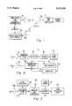
- FIG. 1is an overall block diagram of an enemy signal detection and warning system in accordance with a preferred embodiment of the present invention
- FIG. 2is a detailed block diagram of a coded tag for use in the inventive system of FIG. 1;
- FIG. 3is a detailed block diagram of a passive receiver for use in the inventive system of FIG. 1.
- an enemy source of signalssuch as a radar 10
- radar 10is its transmitting frequency f1. That is, there is no reason to know its location, its purpose for operation or any other characteristics such as the power or modulation of signal transmitted thereby.
- a substitute for radar 10could be an enemy transmitter adapted to transmit at frequency f1.
- Coded tag 12including receive/transmit antenna 12a (or separate receive/transmit antennas) which is exemplary of typically a large plurality of such tags, is mounted on or at least associated with a friendly forces target (illustrated in dashed line 14) such as, for example, a soldier or a combat vehicle, a tank or personnel carrier being typical of such targets.
- a friendly forces targetillustrated in dashed line 14
- a soldier or a combat vehiclea tank or personnel carrier being typical of such targets.
- a suitable coded tag 12is illustrated in detail in FIG. 2 to which attention is now directed.
- Frequency f1 from enemy radar 10 (FIG. 1) or other enemy signal sourceis received at antenna 12r.
- antenna 12rFor illustrative purposes the transmitting and receiving parts of antenna 12a are separated, although in reality they may be separated or may be one common transceiving antenna as shown in FIG. 1.
- Antenna 12ris coupled to a suitable bandpass filter 16 which passes the signal at frequency f1 to a detector 18 which demodulates the signal at frequency f1 received thereat.
- Detector 18is coupled at its output to trigger 20.
- the output of trigger 20is coupled to control inputs of code generator 22, clock source 24 and a transmit oscillator 26.
- Code generator 22serially outputs on line 22a a code, at a rate set by clock 24, which uniquely identifies tag 12 (FIG. 2).
- the output of code generator 22is coupled to a modulator 28, the output of which is coupled to transmit oscillator 26.
- Transmit oscillator 26, when made operational under control of trigger 20,produces a carrier frequency at f2 ⁇ f1 which is radiated by antenna 12t or antenna portion 12t coupled thereto.
- Voltages and currents for the circuits of FIG. 2are supplied by a suitable power supply, e.g., a battery (not shown).
- a passive receiver 30is adjusted to receive frequency f2.
- Receiver 30is located within the area controlled by the friendly forces and therefore not in the location of radar 10.
- Receiver 30processes signals received at antenna 30a attached to receiver 30.
- a typical receiver 30is illustrated in FIG. 3 to which attention is now directed.
- the signal received at antenna 30a at frequency f2is passed to one input of a balanced mixer 34.
- a second input to balanced mixer 34is the output from a local oscillator 36 which is designed to provide a suitable intermediate frequency.
- the output from balanced mixer 34is coupled to an intermediate frequency (IF) amplifier and detector 38 of conventional design.
- the detectoris coupled to a decoder 40 as is a clock source 42.
- Source 42operates at the same rate as clock source 24 (FIG. 2).
- the resulting output of decoder 40which is equal in value to the code produced by device 22 (FIG. 2), is utilized in any suitable code utilization device 44.
- the enemy signal sourcesuch as radar 10 is located in some unknown enemy location. The only thing known about it is that is transmits on frequency f1.
- Coded tag 12is merely representative of a plurality of such coded tags that are mounted on various friendly targets 14. Those targets may include individual combat soldiers or vehicles such as tanks or personnel carriers.
- the friendly targets 14may be located in the territory controlled by the enemy or a territory controlled by friendly forces.
- antenna 12ttransmits at frequency f2 modulated in accordance with the code generated by code generator 22. That frequency, f2, is transmitted by antenna 12t and is received at (with reference now back to FIG. 1) passive receiver 30 and most probably also received at enemy radar 10.
- the assumptionis that radar 10 is not capable of picking up frequency f2, but even if that assumption is not correct, since radar 10 is already receiving frequency f1 from friendly target 14, no special additional information is gained by also receiving frequency f2.
- Frequency f2 received at antenna 30a of passive receiver 30is processed by receiver 30 to produce a signal indicative of the code contained in code generator 22, that signal being received at code utilization device 42 (FIG. 3).
- code utilization device 42FPGA 22
- the signalis received at code utilization device 42 is indicative of two things. First, that, in fact, a friendly target, such as target 14, has been illuminated by a hostile signal, such as radar 10 and therefore it may be presumed that the hostile radar will take some action not to be welcomed by friendly target 14, and, further, the specific code provides an indication in code utilization device 42 of which particular friendly target has been illuminated.
- friendly target 14may be in radio contact with the operator of passive receiver 30 who will signal friendly target 14 to possibly alter operational procedures to avoid damage by the forces controlling enemy radar 10.
Landscapes
- Engineering & Computer Science (AREA)
- Radar, Positioning & Navigation (AREA)
- Remote Sensing (AREA)
- Computer Networks & Wireless Communication (AREA)
- Physics & Mathematics (AREA)
- General Physics & Mathematics (AREA)
- Radar Systems Or Details Thereof (AREA)
Abstract
Description
Claims (7)
Priority Applications (1)
| Application Number | Priority Date | Filing Date | Title |
|---|---|---|---|
| US06/868,993US5343205A (en) | 1986-05-30 | 1986-05-30 | Enemy signal detection and warning system |
Applications Claiming Priority (1)
| Application Number | Priority Date | Filing Date | Title |
|---|---|---|---|
| US06/868,993US5343205A (en) | 1986-05-30 | 1986-05-30 | Enemy signal detection and warning system |
Publications (1)
| Publication Number | Publication Date |
|---|---|
| US5343205Atrue US5343205A (en) | 1994-08-30 |
Family
ID=25352731
Family Applications (1)
| Application Number | Title | Priority Date | Filing Date |
|---|---|---|---|
| US06/868,993Expired - Fee RelatedUS5343205A (en) | 1986-05-30 | 1986-05-30 | Enemy signal detection and warning system |
Country Status (1)
| Country | Link |
|---|---|
| US (1) | US5343205A (en) |
Cited By (2)
| Publication number | Priority date | Publication date | Assignee | Title |
|---|---|---|---|---|
| US5576782A (en)* | 1993-10-29 | 1996-11-19 | Fuji Photo Film Co., Ltd. | Lens-fitted photo film unit for use with taking lenses of different focal length |
| US6774764B2 (en)* | 2000-02-25 | 2004-08-10 | Delphi Technologies, Inc. | Securing system for motor vehicle |
Citations (17)
| Publication number | Priority date | Publication date | Assignee | Title |
|---|---|---|---|---|
| US2602160A (en)* | 1942-09-12 | 1952-07-01 | Wilkins Oscar Lee | Recognition system |
| US3004253A (en)* | 1954-12-20 | 1961-10-10 | Hughes Aircraft Co | Iff system |
| US3079557A (en)* | 1960-11-02 | 1963-02-26 | Texas Instruments Inc | Transponder |
| US3188629A (en)* | 1962-01-30 | 1965-06-08 | Bernarr H Humpherys | Decoder-readout and degarbler |
| US3243801A (en)* | 1963-11-19 | 1966-03-29 | Lab For Electronics Inc | Radar system for identifying targets |
| US3660844A (en)* | 1970-05-04 | 1972-05-02 | Sierra Research Corp | Radar detector and identifier |
| US3896441A (en)* | 1954-04-14 | 1975-07-22 | Sanders Associates Inc | Electric signaling system |
| US3945006A (en)* | 1952-04-04 | 1976-03-16 | The United States Of America As Represented By The Secretary Of The Navy | Radio frequency coding system |
| US3984835A (en)* | 1974-06-03 | 1976-10-05 | Rca Corporation | Homodyne communication system |
| US4003049A (en)* | 1975-07-03 | 1977-01-11 | Rca Corporation | Dual mode automobile collision avoidance radar |
| US4015259A (en)* | 1975-05-21 | 1977-03-29 | The United States Of America As Represented By The Secretary Of The Army | Method and apparatus for interrogating and identifying fixed or moving targets |
| US4129869A (en)* | 1977-01-27 | 1978-12-12 | Mitsubishi Denki Kabushiki Kaisha | Automatical signalling apparatus |
| US4144534A (en)* | 1975-05-01 | 1979-03-13 | The United States Of America As Represented By The Secretary Of The Navy | Battlefield IFF system |
| US4155087A (en)* | 1973-04-20 | 1979-05-15 | The United States Of America As Represented By The Secretary Of The Army | Radar receiver for detecting coded information buried in radar echoes |
| US4177466A (en)* | 1977-11-16 | 1979-12-04 | Lo-Jack Corporation | Auto theft detection system |
| US4242661A (en)* | 1975-03-27 | 1980-12-30 | Stifelsen Institutet for Mikrovagsteknik Vid Tekniska Hogskolan i Stockholm | Device for registration of objects |
| US4358765A (en)* | 1978-08-25 | 1982-11-09 | Stiftelsen Institutet For Mikrovagsteknik Vid Tekniska Hogskolan I Stockholm | Apparatus for producing a single side band |
- 1986
- 1986-05-30USUS06/868,993patent/US5343205A/ennot_activeExpired - Fee Related
Patent Citations (17)
| Publication number | Priority date | Publication date | Assignee | Title |
|---|---|---|---|---|
| US2602160A (en)* | 1942-09-12 | 1952-07-01 | Wilkins Oscar Lee | Recognition system |
| US3945006A (en)* | 1952-04-04 | 1976-03-16 | The United States Of America As Represented By The Secretary Of The Navy | Radio frequency coding system |
| US3896441A (en)* | 1954-04-14 | 1975-07-22 | Sanders Associates Inc | Electric signaling system |
| US3004253A (en)* | 1954-12-20 | 1961-10-10 | Hughes Aircraft Co | Iff system |
| US3079557A (en)* | 1960-11-02 | 1963-02-26 | Texas Instruments Inc | Transponder |
| US3188629A (en)* | 1962-01-30 | 1965-06-08 | Bernarr H Humpherys | Decoder-readout and degarbler |
| US3243801A (en)* | 1963-11-19 | 1966-03-29 | Lab For Electronics Inc | Radar system for identifying targets |
| US3660844A (en)* | 1970-05-04 | 1972-05-02 | Sierra Research Corp | Radar detector and identifier |
| US4155087A (en)* | 1973-04-20 | 1979-05-15 | The United States Of America As Represented By The Secretary Of The Army | Radar receiver for detecting coded information buried in radar echoes |
| US3984835A (en)* | 1974-06-03 | 1976-10-05 | Rca Corporation | Homodyne communication system |
| US4242661A (en)* | 1975-03-27 | 1980-12-30 | Stifelsen Institutet for Mikrovagsteknik Vid Tekniska Hogskolan i Stockholm | Device for registration of objects |
| US4144534A (en)* | 1975-05-01 | 1979-03-13 | The United States Of America As Represented By The Secretary Of The Navy | Battlefield IFF system |
| US4015259A (en)* | 1975-05-21 | 1977-03-29 | The United States Of America As Represented By The Secretary Of The Army | Method and apparatus for interrogating and identifying fixed or moving targets |
| US4003049A (en)* | 1975-07-03 | 1977-01-11 | Rca Corporation | Dual mode automobile collision avoidance radar |
| US4129869A (en)* | 1977-01-27 | 1978-12-12 | Mitsubishi Denki Kabushiki Kaisha | Automatical signalling apparatus |
| US4177466A (en)* | 1977-11-16 | 1979-12-04 | Lo-Jack Corporation | Auto theft detection system |
| US4358765A (en)* | 1978-08-25 | 1982-11-09 | Stiftelsen Institutet For Mikrovagsteknik Vid Tekniska Hogskolan I Stockholm | Apparatus for producing a single side band |
Cited By (2)
| Publication number | Priority date | Publication date | Assignee | Title |
|---|---|---|---|---|
| US5576782A (en)* | 1993-10-29 | 1996-11-19 | Fuji Photo Film Co., Ltd. | Lens-fitted photo film unit for use with taking lenses of different focal length |
| US6774764B2 (en)* | 2000-02-25 | 2004-08-10 | Delphi Technologies, Inc. | Securing system for motor vehicle |
Similar Documents
| Publication | Publication Date | Title |
|---|---|---|
| US4646090A (en) | Codeable identifying tag and method of identification thereof | |
| US4808999A (en) | Towed decoy with fiber optic link | |
| US5519403A (en) | Global positioning system communications multi-interface | |
| US5579008A (en) | Electronic license plate apparatus and method | |
| US3161870A (en) | System for increasing the detection range of a group of search radars | |
| US3544995A (en) | Navigation method with the aid of satellites | |
| US4596988A (en) | Remote controlled tracking transmitter and tracking support system | |
| US3400393A (en) | Weapon safety mechanism | |
| US6081222A (en) | Joint surveillance target attack system combat transponder | |
| EP3593164B1 (en) | Innovative locator system, related low power consumption regenerative transponder and related localization method and service | |
| US5142288A (en) | Electro-optical IFF system | |
| US5375008A (en) | Systems for distinguishing between friendly ground targets and those of a foe | |
| US20100289691A1 (en) | Simplifying and cost-effective IR-RF combat identification friend-or foe (IFF) system for ground targets | |
| EP0634021A4 (en) | Beam steered laser iff system. | |
| US4694297A (en) | Remote identification device | |
| US4015259A (en) | Method and apparatus for interrogating and identifying fixed or moving targets | |
| US4144534A (en) | Battlefield IFF system | |
| KR940020280A (en) | Automatic vehicle recognition system and method for identifying lanes of vehicles | |
| US5748138A (en) | Synchronous identification of friendly targets | |
| US9086472B2 (en) | Multi-transceiver RF alert system for preventing hunting accidents | |
| US5170168A (en) | Identification of friend from foe device | |
| US3631485A (en) | Guidance system | |
| GB1383564A (en) | Umpires ray gun for use in weapon training systems | |
| US4823139A (en) | Electronic countermeasure system | |
| US6097330A (en) | Optical friendly fire avoidance system |
Legal Events
| Date | Code | Title | Description |
|---|---|---|---|
| AS | Assignment | Owner name:RCA CORPORATION, A CORP. OF DE. Free format text:ASSIGNMENT OF ASSIGNORS INTEREST.;ASSIGNOR:NOWORGRODZKI, MARKUS;REEL/FRAME:004562/0017 Effective date:19860529 | |
| AS | Assignment | Owner name:GENERAL ELECTRIC COMPANY Free format text:MERGER;ASSIGNOR:R C A CORPORATION, A CORP. OF DE.;REEL/FRAME:004837/0618 Effective date:19880129 Owner name:GENERAL ELECTRIC COMPANY,STATELESS Free format text:MERGER;ASSIGNOR:R C A CORPORATION, A CORP. OF DE.;REEL/FRAME:004837/0618 Effective date:19880129 | |
| AS | Assignment | Owner name:MARTIN MARIETTA CORPORATION, MARYLAND Free format text:ASSIGNMENT OF ASSIGNORS INTEREST;ASSIGNOR:GENERAL ELECTRIC COMPANY;REEL/FRAME:007046/0736 Effective date:19940322 | |
| FEPP | Fee payment procedure | Free format text:PAYOR NUMBER ASSIGNED (ORIGINAL EVENT CODE: ASPN); ENTITY STATUS OF PATENT OWNER: LARGE ENTITY | |
| AS | Assignment | Owner name:LOCKHEED MARTIN CORPORATION, MARYLAND Free format text:ASSIGNMENT OF ASSIGNORS INTEREST;ASSIGNOR:MARTIN MARIETTA CORPORATION;REEL/FRAME:008628/0518 Effective date:19960128 | |
| REMI | Maintenance fee reminder mailed | ||
| LAPS | Lapse for failure to pay maintenance fees | ||
| FP | Lapsed due to failure to pay maintenance fee | Effective date:19980830 | |
| STCH | Information on status: patent discontinuation | Free format text:PATENT EXPIRED DUE TO NONPAYMENT OF MAINTENANCE FEES UNDER 37 CFR 1.362 |