US5343043A - Remote sensor device for monitoring motor vehicle exhaust systems with high speed sampling - Google Patents
Remote sensor device for monitoring motor vehicle exhaust systems with high speed samplingDownload PDFInfo
- Publication number
- US5343043A US5343043AUS08/120,069US12006993AUS5343043AUS 5343043 AUS5343043 AUS 5343043AUS 12006993 AUS12006993 AUS 12006993AUS 5343043 AUS5343043 AUS 5343043A
- Authority
- US
- United States
- Prior art keywords
- detector
- rotating mirror
- detectors
- mirror
- pulse
- Prior art date
- Legal status (The legal status is an assumption and is not a legal conclusion. Google has not performed a legal analysis and makes no representation as to the accuracy of the status listed.)
- Expired - Fee Related
Links
- 238000005070samplingMethods0.000titleclaimsdescription46
- 238000012544monitoring processMethods0.000titledescription18
- 239000003344environmental pollutantSubstances0.000claimsabstractdescription18
- 231100000719pollutantToxicity0.000claimsabstractdescription18
- 230000003287optical effectEffects0.000claimsabstractdescription16
- 239000003990capacitorSubstances0.000claimsdescription17
- 238000001514detection methodMethods0.000claimsdescription6
- 238000012546transferMethods0.000abstractdescription7
- 230000010354integrationEffects0.000description18
- 238000010586diagramMethods0.000description13
- 239000007787solidSubstances0.000description7
- 238000013459approachMethods0.000description5
- 238000005259measurementMethods0.000description5
- 238000009987spinningMethods0.000description4
- 230000006870functionEffects0.000description3
- 238000004519manufacturing processMethods0.000description3
- 238000012360testing methodMethods0.000description3
- 229910052782aluminiumInorganic materials0.000description2
- XAGFODPZIPBFFR-UHFFFAOYSA-NaluminiumChemical compound[Al]XAGFODPZIPBFFR-UHFFFAOYSA-N0.000description2
- 238000006243chemical reactionMethods0.000description2
- 239000000203mixtureSubstances0.000description2
- 238000012545processingMethods0.000description2
- 230000035945sensitivityEffects0.000description2
- 101100328360Schizosaccharomyces pombe (strain 972 / ATCC 24843) clr1 geneProteins0.000description1
- 238000003915air pollutionMethods0.000description1
- 230000035559beat frequencyEffects0.000description1
- 230000005540biological transmissionEffects0.000description1
- 239000000872bufferSubstances0.000description1
- 238000002485combustion reactionMethods0.000description1
- 239000012141concentrateSubstances0.000description1
- 238000010276constructionMethods0.000description1
- 238000001816coolingMethods0.000description1
- 230000007423decreaseEffects0.000description1
- 230000003247decreasing effectEffects0.000description1
- 238000006073displacement reactionMethods0.000description1
- 230000009977dual effectEffects0.000description1
- 230000000694effectsEffects0.000description1
- 238000003912environmental pollutionMethods0.000description1
- 230000005669field effectEffects0.000description1
- 238000001914filtrationMethods0.000description1
- 238000010438heat treatmentMethods0.000description1
- 230000000977initiatory effectEffects0.000description1
- 238000007689inspectionMethods0.000description1
- 229940056932lead sulfideDrugs0.000description1
- 229910052981lead sulfideInorganic materials0.000description1
- 239000011159matrix materialSubstances0.000description1
- 230000015654memoryEffects0.000description1
- 229910052751metalInorganic materials0.000description1
- 239000002184metalSubstances0.000description1
- 238000000034methodMethods0.000description1
- 238000002360preparation methodMethods0.000description1
- 150000003839saltsChemical class0.000description1
- GGYFMLJDMAMTAB-UHFFFAOYSA-NselanylideneleadChemical compound[Pb]=[Se]GGYFMLJDMAMTAB-UHFFFAOYSA-N0.000description1
- 230000005236sound signalEffects0.000description1
- 230000003068static effectEffects0.000description1
- 238000003860storageMethods0.000description1
- 238000013024troubleshootingMethods0.000description1
- 230000000007visual effectEffects0.000description1
Images


Classifications
- G—PHYSICS
- G01—MEASURING; TESTING
- G01N—INVESTIGATING OR ANALYSING MATERIALS BY DETERMINING THEIR CHEMICAL OR PHYSICAL PROPERTIES
- G01N21/00—Investigating or analysing materials by the use of optical means, i.e. using sub-millimetre waves, infrared, visible or ultraviolet light
- G01N21/17—Systems in which incident light is modified in accordance with the properties of the material investigated
- G01N21/25—Colour; Spectral properties, i.e. comparison of effect of material on the light at two or more different wavelengths or wavelength bands
- G01N21/31—Investigating relative effect of material at wavelengths characteristic of specific elements or molecules, e.g. atomic absorption spectrometry
- G01N21/35—Investigating relative effect of material at wavelengths characteristic of specific elements or molecules, e.g. atomic absorption spectrometry using infrared light
- G01N21/3504—Investigating relative effect of material at wavelengths characteristic of specific elements or molecules, e.g. atomic absorption spectrometry using infrared light for analysing gases, e.g. multi-gas analysis
- G—PHYSICS
- G01—MEASURING; TESTING
- G01N—INVESTIGATING OR ANALYSING MATERIALS BY DETERMINING THEIR CHEMICAL OR PHYSICAL PROPERTIES
- G01N21/00—Investigating or analysing materials by the use of optical means, i.e. using sub-millimetre waves, infrared, visible or ultraviolet light
- G01N21/17—Systems in which incident light is modified in accordance with the properties of the material investigated
- G01N2021/1793—Remote sensing
- G—PHYSICS
- G01—MEASURING; TESTING
- G01N—INVESTIGATING OR ANALYSING MATERIALS BY DETERMINING THEIR CHEMICAL OR PHYSICAL PROPERTIES
- G01N21/00—Investigating or analysing materials by the use of optical means, i.e. using sub-millimetre waves, infrared, visible or ultraviolet light
- G01N21/17—Systems in which incident light is modified in accordance with the properties of the material investigated
- G01N21/25—Colour; Spectral properties, i.e. comparison of effect of material on the light at two or more different wavelengths or wavelength bands
- G01N21/31—Investigating relative effect of material at wavelengths characteristic of specific elements or molecules, e.g. atomic absorption spectrometry
- G01N21/35—Investigating relative effect of material at wavelengths characteristic of specific elements or molecules, e.g. atomic absorption spectrometry using infrared light
- G01N21/3504—Investigating relative effect of material at wavelengths characteristic of specific elements or molecules, e.g. atomic absorption spectrometry using infrared light for analysing gases, e.g. multi-gas analysis
- G01N2021/3513—Open path with an instrumental source
Definitions
- the present inventionrelates to the monitoring and detection of vehicle emitted pollutants.
- the inventionhas particular application to monitoring the exhaust emissions of motor vehicles under actual operating conditions.
- Detecting and limiting environmental pollutionhas become an area of the utmost importance to industrialized societies. Substantial effort and resources have been committed to detecting and curbing sources of industrial pollution in all forms.
- One of the major contributors to air pollutionis the internal combustion engine which is used to power motor vehicles. It is highly desirable to measure exhaust emissions from a vehicle under actual operating conditions and not in a static situation such as while idling at low RPM. Dynamic testing under actual operating conditions not only provides a more accurate indication of pollutant emissions, but also makes vehicle tampering for the purpose of circumventing the pollution test equipment virtually impossible.
- U.S. Pat. No. 4,924,095discloses a remote gas analyzer for motor vehicle exhaust emission surveillance in which a planar array of gas analyzer beams intersects substantially an entire cross-sectional segment of the exhaust gas plume in order to determine the volume concentration of first gas pollutants in the exhaust of a motor vehicle passing the array. These first pollutants have a relatively high and more easily detectable concentration.
- a second, multi-spectral gas analyzer beamintersects the exhaust to determine the change in concentration of the less prevalent pollutants with respect to ambient, and also determines the change in concentration of the first pollutants.
- the gas analyzer beamstransit the exhaust gas plume in a first path and are then reflected back through the plume in a second path by a matrix array of retro-reflectors.
- U.S. Pat. No. 5,210,702issued May 11, 1993, for remote detecting, measuring and recording of NO x , CO, CO 2 , HC and H 2 O levels from the exhaust of moving motor vehicles.
- An optical mechanismsplits an infrared (IR) beam into two to four components, and devices are positioned for receiving each of the IR components and generating two to four signals indicative of, for example, CO, CO 2 , HC and H 2 O.
- An IR source and the receiving mechanismare aligned on opposite sides of a roadway and a visual recording device is positioned for visually recording the vehicle and test results.
- the IR beammakes a single pass across the roadway through the vehicle's exhaust plume between the IR source and detector.
- a polygon-shaped rotating mirrorreflects the IR beam after passing through the vehicle's exhaust plume onto a plurality of detectors, each adapted to measure the concentration of a respective pollutant.
- IR detectorsare highly temperature sensitive and exhibit increased resistivity with decreasing temperature.
- An IR detectortypically provides a maximum output at -70° C.
- Thermo-electric coolerscapable of reducing the temperature of a detector 21° C. below ambient are used to improve detector signal-to-noise (S/N) ratio. By running the coolers at maximum power, the detected signal level may be increased.
- S/Ndetector signal-to-noise
- Some prior art gas analyzersutilize a number of manually adjustable potentiometers to improve the S/N ratio by tuning the detector circuit for operation at a given temperature.
- An important feature of the inventionis the use of a unitary lateral transfer mirror on one side of a roadway in combination with an IR beam source and detector on the other side of the roadway which facilitates alignment of the optical elements in the vehicle emissions monitoring apparatus.
- Another important feature of the inventionis the use in a roadside vehicle emissions monitoring apparatus of an improved IR beam source and detector employing a plurality of adjustable, computer-controlled potentiometers for compensating for temperature variation and a high speed IR beam sampling arrangement which allows for high frequency re-calibration of the IR detector to reduce errors caused by circuit drift.
- apparatusfor high speed detection of pollutants in an exhaust plume of a motor vehicle, wherein an IR beam is directed through the exhaust plume and interacts with the pollutants
- the apparatuscomprising: optical means including a rotating mirror for receiving the IR beam after transit through the exhaust plume, wherein the rotating mirror includes N reflecting side walls and rotates at an angular velocity V; a plurality of IR detectors each adapted to detect a specific pollutant in the exhaust plume, wherein the IR detectors are arranged in a spaced array adjacent to the rotating mirror and adapted to receive the IR beam reflected from the side walls of the rotating mirror, wherein the IR beam reflected from one of the side walls of the rotating mirror is sequentially directed onto each of the detectors and wherein each of the IR detectors receives the IR beam as a series of IR pulses; and digital timing means coupled to the rotating mirror and responsive to the angular velocity V thereof and further coupled to each of the IR detectors for actuating the IR detectors in a time
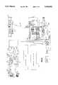
- FIG. 1is a simplified schematic diagram of a remote sensor device for monitoring motor vehicle exhaust emissions in accordance with the present invention
- FIG. 2is a combined schematic and block diagram of the remote sensor device for monitoring motor vehicle exhaust emissions of FIG. 1;
- FIG. 3is a plan view of the detector optics used in the remote sensor device for monitoring motor vehicle exhaust emissions of FIG. 1;
- FIG. 4is a side elevation view of the detector optics arrangement shown in FIG. 3;
- FIG. 5is a simplified schematic diagram of an arrangement for aligning beam source optics in the remote sensor device of the present invention during manufacture
- FIG. 6is a combined schematic and block diagram of an IR detector circuit used in the remote sensor device of the present invention.
- FIG. 7is a combined block and schematic diagram of a digital timing and analog integration sampling circuit for use in the IR detector of the present invention.
- FIG. 8is a schematic diagram of the analog portion of the sampling circuit of FIG. 7;
- FIGS. 9a and 9bare respectively graphic illustrations of the variation of received IR signal amplitude and the integration of the received IR signal by IR signal processing circuitry in the remote sensor device over time;
- FIG. 10is a simplified flow chart illustrating the steps carried out by IR signal detection circuitry for providing an audio and/or video signal for optical alignment of the remote sensor device.
- FIG. 1there is shown a simplified schematic diagram of a motor vehicle exhaust emission monitoring system 10 in accordance with the principles of the present invention.
- the exhaust emission monitoring system 10is designed for non-intrusive measurement of vehicular emission by generating and monitoring an IR beam emitted and reflected approximately 10-18 inches above a roadway.
- Gasoline powered vehiclesdrive through the beam and their exhaust "interferes" with the transmission of the IR beam and appropriate detectors measure and calculate the CO, HC and CO 2 vehicular emissions and provide a digitized video picture of the rear of the vehicle including its license plate.
- FIG. 1is a simplified plan view in schematic and block diagram form of the exhaust emission monitoring system 10
- a motor vehicle 30 travelling along a roadway 26passes between a gas analyzer 12 and a lateral transfer mirror (LTM) 14 disposed on opposing sides of the roadway.
- Gas analyzer 12includes a source optics module 16 and a detector optics module 18.
- the source and detector optics modules 16, 18include a laser for aligning the source and detector optics with the LTM 14 prior to use.
- the source optics module 16includes an IR source for emitting an IR beam which is 6 inches in diameter in a particular embodiment.
- the IR sourceemits an IR beam 22 across roadway 26 and onto a first reflecting surface 14a of the LTM 14.
- LTM 14is disposed in and supported by a housing 20.
- the incident IR beam 22is reflected from the LTM's first reflecting surface 14a onto a second reflecting surface 14b.
- the second reflecting surface 14bdirects the reflected IR beam 24 back across the roadway 26 and onto the detector optics module 18 of the gas analyzer 12.
- a video camera 32connected to the gas analyzer 12 via a cable 34 takes a photograph of the aft portion of vehicle 30 including its license plate 30a. This provides an operator of the exhaust emission monitoring system 10 with a permanent record of the identity of the vehicle and the exhaust emission being monitored.
- the gas analyzer 12further includes an operator's control/display panel 58 including an arrangement of control elements and displays.
- Video camera 32 in one embodimentis of the digital type to provide a digitized still image video picture of the vehicle's license plate 30a as the IR beam is directed through its exhaust plume 28.
- the digital imagemay then be stored on a disc file 35 in digital form for use by computers and computerized equipment.
- a third generally planar panel 14cDisposed intermediate and coupled to the first and second reflecting surfaces 14a, 14b of the LTM 14 is a third generally planar panel 14c.
- the two reflectors 14a, 14b and the planar panel 14c disposed therebetweenform an integral structure to facilitate alignment of incident and reflected IR beams 22, 24 with source and detector optics modules 16, 18.
- Planar panel 14cis comprised of milled aluminum in one embodiment and may be used as a target for laser beam 15 for aligning the source and detector optics modules with the LTM 14.
- the laser beam source and detector 17is thus used in combination with planar panel 14c of the LTM 14 for gross alignment of the optical elements of the motor vehicle exhaust emission monitoring system 10.
- FIG. 3there is shown a plan view of the detector optics module 18 within the gas analyzer 12.
- a side elevation view of the detector optics module 18is shown in FIG. 4.
- the reflected IR beam 24is directed into the detector optics module 18 and onto a concave primary focusing mirror 38.
- the primary focusing mirror 38reflects the IR beam 24 downward and onto a multi-sided rotating mirror 36.
- rotating mirror 36is rotationally displaced in a counter-clockwise direction and reflects the IR beam in a sequential manner onto first, second, third and fourth concave secondary mirrors 40, 42, 44 and 46.
- the concave secondary mirrors 40, 42, 44 and 46are arranged in a semi-circular, horizontally aligned, spaced array for focusing the IR beam onto respective IR detectors.
- the first, second, third and fourth concave secondary mirrors 40, 42, 44 and 46respectively reflect and focus the IR beam onto a CO detector 48, a HC detector 50, a CO 2 detector 52 and a reference detector 54.
- IR beam 24is reflected onto each of the concave secondary mirrors in a sequential manner, beginning with the fourth mirror 46 and ending with the first mirror 40.
- the detector optics module 18is designed to receive an IR beam 24 on the order of 4 inches square and to concentrate "pulses" of that light on the detectors.
- a 3 inch primary concave mirror 38a 12,000 RPM rotating mirror 36 comprised of a 12 faceted polygon and driven by a motor 37, and four 38 mm concave secondary mirrors 40, 42, 44 and 46.
- Thisprovides a pulse frequency of the IR beam on each detector of 2,400 pulses per second.
- Each of the detectorsis comprised of lead sulfide or lead selenide in a preferred embodiment.
- the IR beamis thus sequentially directed onto the fourth, third, second and first concave secondary mirrors 46, 44, 42 and 40 in this order.
- Drive motor 37provides an output signal /OPTO representing the speed of rotation of the spinning mirror 36.
- the /OPTO signalis provided to a digital timing and integration sampling circuit described below for high speed sampling of the detected IR signal.
- FIG. 5there is shown a simplified schematic diagram of an arrangement for aligning the source optics and detector optics during manufacture.
- a laser beam generator 64is mounted to the detector base 56.
- Laser beam 66is directed onto a source mirror 68 within the beam source optics 60.
- Source mirror 68reflects the laser beam 66 onto an IR source 70.
- the IR source 70 and source mirror 68are mounted to a source optics platform 72.
- Laser 64is positioned at the same elevation above the detector base 56 as the previously described primary focusing mirror 38 shown in FIG. 4. If the beam source optics 60 are aligned correctly, laser beam 66 will strike the IR source 70 midway between its top and bottom portions and halfway along its length.
- the IR source 70 as well as source mirror 68may be translationally displaced and/or rotated for proper alignment of the beam source optics 60 with laser beam 66. With the beam source optics 60 properly aligned, an IR beam emitted by IR source 70 and reflected by source mirror 68 will be incident upon the primary focusing mirror 38 within the detector optics module 18 for focusing on the various IR detectors as described above.
- the IR detector 80includes a CO detector circuit 82, an HC detector circuit 84, a CO 2 detector circuit 86, and a reference detector circuit 88. Details of the CO and HC detector circuits 82, 84 are shown in the figure, with the CO 2 and reference detector circuits 86, 88 shown simply as blocks, it being understood that all of the detector circuits have essentially the same composition and operate in the same manner.
- the CO and HC detector circuits 82, 84share a common computer controlled potentiometer 110 and operate in essentially the same manner, with details of the operation of only the CO detector circuit set forth herein for simplicity.
- the CO 2 and reference detector circuits 86, 88similarly share a common computer controlled potentiometer, which is not shown in the figure for simplicity.
- the CO detector circuit 82is energized by a DC power supply 138 which includes a DC-to-DC converter 139 and a field effect transistor (FET) 140. Resistor 90 in series with a 50 VDC input biases the CO detector element 128. Capacitor 92 DC isolates the signal.
- the CO detector circuit 82further includes an CO detector element 128 whose resistivity changes with temperature. Thus, as the temperature of the CO detector element 128 decreases, its resistance increases. CO detector element 128 includes a lead salt detector element 128a, a thermistor 128b and a thermoelectric cooler 128c for reducing the temperature of the detector element.
- Signal groundis provided to one input of a differential amplifier 94, with the output of the CO detector element 128 provided to its other input. Also coupled to the input of differential amplifier 94 are jumper terminals 96 which allow for reducing large input signal levels to the CO detector circuit 82. By connecting a shunt (not shown) across jumper terminals 96 the output from CO detector circuit 82 may be reduced to compensate for a large input signal level.
- a capacitor 102 coupled to differential amplifier 94provides an offset compensation to prevent high frequency signals such as RF noise from causing the amplifier to oscillate.
- the combination of capacitor 104 and resistor 106 along with capacitor 100 and resistor 98provides for high frequency filtering and gain control of the output of differential amplifier 94. These filter networks provide for high frequency roll-off and reduce the sensitivity of the CO detector circuit 82 to frequencies generally above 50 kHz.
- the filtered output of differential amplifier 94is provided through resistor 108 to the computer controlled potentiometer 110.
- Potentiometer 110includes a resistor ladder network and functions as a dual computer controlled potentiometer in that it also operates with the HC detector circuit 84. Resistor 108 and clamping diodes 112 and 114 maintain the input to potentiometer 110 between plus and minus five volts so that the output of the potentiometer does not exceed predetermined limits. The output of potentiometer 110 is provided to a differential amplifier 116, the output of which is fed back to the potentiometer for gain control. With 256 resistors in potentiometer 110, the gain of differential amplifier 116 may be controlled in a step-wise fashion over plus or minus 128 increments. With the gain of differential amplifier 116 controlled by potentiometer 110, the output of the differential amplifier is provided to analog sampling circuitry described below.
- IR detector 80further includes an analog multiplexer 126 having an input pin 130b.
- Input pin 130bis coupled to an output pin 130a of the CO detector element 128 for providing the analog multiplexer 126 with an indication of the temperature of operation of the IR detector element.
- Analog multiplexer 126is also coupled to the DC power supply 138 via a voltage feedback (VFB) line 134.
- the 50 VDC output from power supply 138is divided down by the combination of a capacitor 145 and resistors 141 and 143 to provide 1.2 VDC on the VFB line 134 to the analog multiplexer 126.
- Analog multiplexer 126verifies that power supply 138 is operating at 50 VDC.
- Input pin 132 of analog multiplexer 126receives a /OPTO signal from the rotating mirror's drive motor 37 (FIG. 4) representing the speed of rotation of mirror 36 which signal is further provided to computer 118 via amplifier 136.
- Analog multiplexer 126provides analog output signals representing IR detector operating temperature via a voltage follower amplifier 136 to a computer 118.
- Computer 118in a preferred embodiment is an 80186 microprocessor-based computer.
- the I 2 C chip 120serves as an interface between computer 118 and potentiometer 110 and first and second electrically erasable read only memories (“EEPROMs") 122 and 124, described below.
- Pins 110a and 111a coupled to the I 2 C chip 120are further coupled to input pins 110b and 111b, respectively, of potentiometer 110.
- the control input provided from computer 118 via the I 2 C chip 120controls, among other things, the setting of potentiometer 110.
- the amplitude of the output signal from CO detector circuit 82 representing the detected IR beamis controlled via computer 118.
- the output from the I 2 C chip 120allows for up and down toggling of the computer controlled potentiometers within each of the respective detector circuits.
- the resistance of each resistance ladder potentiometermay be precisely adjusted in a stepwise manner for precisely controlling the output signal level of the detector circuit. This ensures that the output signals from each of the gas detector circuits 82, 84, 86 and 88 are precisely adjusted to compensate for differences in the operating temperatures of the detector elements in each of these circuits.
- Computer 118also provides outputs to the aforementioned first and second EEPROMs 122 and 124.
- EEPROMs 122 and 124store calibration coefficients for each of the computer controlled potentiometers from computer 118.
- the calibration data stored in EEPROM's 122 and 124includes specific gas coefficients for each detector circuit.
- FIG. 7there is shown a combined block and schematic diagram of a digital timing and analog integration sampling circuit 152 for use in the IR detector portion of the remote sensor device of the present invention.
- Digital timing and analog integration sampling circuit 152provides for high speed sampling of the detector outputs.
- Prior approaches in IR gas analyzers incorporating a rotating mirror arrangementprovide for sampling of the gas with every two (2) revolutions of the rotating mirror. With the rotating mirror typically spinning at a speed of 12,000 RPM, the gas is sampled 6000 times per minute.
- the present invention employing the digital timing and analog integration sampling circuit 152 of FIG. 7allows for sampling of the gas with each pulse provided by a respective flat of the rotating mirror.
- the digital timing and analog integration sampling circuit 152allows for sampling of the gas at a rate of 12 times 12000 RPM, or 144000 times per minute. In other words, each time an IR pulse from the rotating mirror is incident upon the detectors, the received signal is analog-to-digital converted to provide a digital representation of each received IR pulse. This extremely high rate of gas sampling minimizes the effect of noise variations in the detectors and associated circuitry for more accurate analysis of the composition of the gas. With reference to FIG. 7 as well as to the pulse diagrams of FIG. 9a and 9b, the operation of the digital timing and analog integration sampling circuit 152 will now be described.
- the digital timing and analog integration sampling circuit 152samples the detector's output in the absence of an IR beam incident upon the detector.
- the sampling circuitthen waits for a designated period of time as determined by the speed of rotation of the rotating mirror, and then again samples the detector and stores the sampled value on a capacitor in integrating the IR pulse received by the detector.
- the stored valueis then analog-to-digital converted to provide a digital representation of the concentration of a pollutant in the vehicle's exhaust plume, which value is then stored.
- the digital timing and analog integration sampling circuit 152includes a programmable logic chip (PLC) 154 which receives, among other signals, a clock input TOUT1 from a master clock (not shown) and the optical pick-up output /OPTO from the drive motor 37 of rotating mirror 36.
- the optical pick-up signal /OPTOsynchronizes operation of the digital timing and analog integration sampling circuit 152 with the high speed rotation of mirror 36, while the clock input TOUT1 synchronizes the digital timing and analog integration sampling circuit with computer 118 and other portions of the remote sensor device.
- the digital timing and analog integration sampling circuit 152counts a selected time interval, following which the IR detector circuits sample the received IR beam.
- the time at which the IR beam is sampledis determined by the speed of rotation of mirror 36.
- the /OPTO signalis provided to a programmable logic chip 154 which functions as a counter for initiating the countdown following receipt of the /OPTO input signal.
- PLC 154After a predetermined time interval, PLC 154 provides an output to first and second decoders 166 and 168 as well as to an analog multiplexer 156. Decoders 166 and 168 provide timed store and clear inputs to an analog sampling circuit 170 described in detail below. Also provided to the analog sampling circuit 170 is the aforementioned outputs from the individual detector circuits shown in FIG. 6 and described in detail above. The outputs from the analog sampling circuit 170 representing the detected IR signals are also provided to the analog multiplexer 156.
- analog multiplexer 156converts the analog output of sampling circuit 170 to digital form.
- A/D converter 160converts the analog output of sampling circuit 170 to digital form.
- the digital outputs of the A/D converter 160are then provided via buffers 162 and 164 to computer 118.
- Computer 118provides a digital signal representing the detected IR signal to the aforementioned control/display panel 58 for display for a system operator.
- the curve in FIG. 9arepresents a series of pulses received by each of the detectors in the IR detector circuit of FIG. 6.
- the curve in FIG. 9billustrates the integration of the received pulses shown in FIG. 9a over time by the digital timing and analog integration sampling circuit 152. With a speed of rotation of 12000 RPM, the period of received IR pulses is 416 microseconds with a 12 faceted mirror.
- the digital timing and analog integration sampling circuit 152 shown in FIG. 7integrates the pulses received from each detector circuit as shown in FIG. 9b and re-zeroes, or clears, the detector circuits after receipt of an IR pulse in preparation for receipt of the next IR pulse as described below.
- the analog sampling circuit 170includes a CO analog sampling circuit 200, an HC analog sampling circuit 202, a CO 2 analog sampling circuit 204, and a reference analog sampling circuit 206. Details of only the CO analog sampling circuit 200 are shown in the figure for simplicity, as the remaining analog sampling circuits are similar in configuration and operation.
- differential amplifier 208In the CO analog sampling circuit 200 via respective voltage divider networks comprised of resistors 207, 209 and 211, 213.
- One input to differential amplifier 208is the output from the CO detector circuit 82 of FIG. 6, while the other input is a reference voltage V REF .
- Differential amplifier 208operates as a voltage follower and compensates for any power or grounding problems in the input line.
- the output of differential amplifier 208is provided via the combination of a solid state switch 210 and grounded capacitor 212 to one input of an operational amplifier 220.
- A/CLR1 inputis provided to the first solid state switch 210 as well as to a second solid state switch 222 from decoder 166 as shown in FIG.
- Solid state switch 210is closed in the absence of an IR input to the detector, representing a zeroing of the detector. Thus, solid state switch 210 is closed for a short period, typically 10-15 microseconds, allowing capacitor 212 to charge to a level representing the detector voltage in the absence of an IR beam. Switch 210 and capacitor 212 thus operate as a sample and hold circuit, providing an input to operational amplifier 220 representing the absence of an IR input to the detector.
- the charge of capacitor 216is integrated via a resistor 214 and is applied to one input of operational amplifier 218. Capacitor 216 is charged over time, such that when the charging pulse is removed, the output of differential amplifier 218 is essentially at the same level as the charge on capacitor 216.
- the detected IR pulsehas thus been integrated as represented by the output of operational amplifiers 218 and 220 which function as a differential common mode amplifier.
- the integrated detected IR signalis provided from operational amplifiers 218 and 220 to operational amplifier 224 via respective networks comprised of resistors 228, 232 and 230, 234.
- the output of operational amplifier 224is provided to another sample and hold circuit comprised of solid state switch 226 and grounded capacitor 236.
- the sample and hold circuitis updated upon receipt by switch 226 of a /STORE input from the aforementioned decoder 166 shown in FIG. 7.
- the output of the sample and hold circuit comprised of solid state switch 226 and capacitor 236is provided to operational amplifier 238, the output of which is low pass filtered by means of the combination of resistors 240, 244 and 248 and capacitors 242, 246 and 250.
- the low pass filtered output of operational amplifier 238is provided to operational amplifier 252 and thence to the analog multiplexer 156 in the digital timing and analog integration sampling circuit 152 as shown in previously described FIG. 7.
- CO analog sampling circuit 200operates to sample the CO detector circuit 82 for a detected IR input, temporarily store a detected IR input and then provide the IR input to computer 118 for processing and storage. Each of these operations is performed in a precisely timed manner determined by the rotational speed of spinning mirror 36.
- the output of the detectoris sampled a predetermined time interval following detection of the absence of the IR beam on the detector, where the predetermined time interval is determined by the rotational speed of the spinning mirror.
- FIG. 10there is shown a flow chart of the operations carried out primarily by computer 118 in the remote sensor device for providing either an audio or optical signal for precisely aligning the optical elements in the source and detector modules optics 16 and 18 with the LTM 14.
- an analog IR signalis detected such as by the CO detector circuit 82 which is provided to the analog sampling circuit 170 shown in FIG. 8.
- the output of the analog sampling circuit 170is provided to the analog multiplexer 156 which in combination with operational amplifier 158 and A/D converter 160 converts the analog IR signal to digital form, with a count N representing signal amplitude as shown in step 146.
- the digitized detected IR signalis then provided to computer 118 which at step 148 determines whether the count N is greater than 3000 but less than 9500.
- twenty-four A/D conversionsare used to sample the detector signal and to detect a count range of from 0 to 2048 counts.
- the maximum number of counts with twenty-four A/D conversions per detectoris 49,152 divided by 5, or 9,830.
- the number of countsis divided by 5 to provide an arbitrary maximum count of 9,500.
- a full scale countis arbitrarily set at 8500, with a 3000 count establishing the low end of the detection of an IR signal.
- Computer 118therefore at step 148 compares the number of counts in the detected IR signal with, the low end limit of 3000 and the upper end limit of 9500.
- an audio beeper 174 and/or a light source 176 coupled to the computeris turned off, indicating absence of a received IR signal. If at step 148 it is determined that the count of the detected IR signal is between 3000 and 9500, the program stored in computer 118 branches to step 150 and pulses the audio beeper 174 and/or light source 176 with a signal count N. The operator of the remote sensor device then adjusts the optical components of the system, such as the lateral transfer mirror, to increase the count, or pulse rate, of the audio and/or light signals until the beat frequency is maximized.
- the apparatusemploys an IR beam directed twice through the vehicle's exhaust plume using a combination IR source and detector module on one side of the roadway and a lateral transfer mirror on the other side of the roadway.
- the lateral transfer mirrorprovides a fixed, precisely defined horizontal displacement between the emitted and reflected beams which permits close spacing between the source and detector optics such as in a single module.
- the lateral transfer mirrorincludes two transversely oriented reflectors rigidly coupled by an intermediate aluminum panel which provides an integral structure which facilitates optical alignment of the apparatus.
- the IR detector moduleincludes a high speed, rotating mirror arrangement for sequentially directing the reflected IR beam in a pulsed manner onto a plurality of spaced detector elements, each adapted for detecting a specific pollutant.
- the IR beamis sampled with each IR pulse provided to the detectors at a rate greater than the speed of rotation of the mirror which nominally operates at 12,000 RPM. This high speed sampling rate is used to calibrate each detector circuit at a high rate to minimize circuit drift and other sources of measurement inaccuracy.
- a pulsed output representing the detected IR signalis provided to an audio beeper and/or a visible light which are pulsed so as to indicate the strength of the received IR signal.
- the optical elements of the source and detector opticsare adjusted until the audio beeper and/or light source provide a maximized beep and/or light pulse frequency.
Landscapes
- Physics & Mathematics (AREA)
- Spectroscopy & Molecular Physics (AREA)
- Health & Medical Sciences (AREA)
- Life Sciences & Earth Sciences (AREA)
- Chemical & Material Sciences (AREA)
- Analytical Chemistry (AREA)
- Biochemistry (AREA)
- General Health & Medical Sciences (AREA)
- General Physics & Mathematics (AREA)
- Immunology (AREA)
- Pathology (AREA)
- Investigating Or Analysing Materials By Optical Means (AREA)
Abstract
Description
Claims (6)
Priority Applications (1)
| Application Number | Priority Date | Filing Date | Title |
|---|---|---|---|
| US08/120,069US5343043A (en) | 1993-04-13 | 1993-09-13 | Remote sensor device for monitoring motor vehicle exhaust systems with high speed sampling |
Applications Claiming Priority (2)
| Application Number | Priority Date | Filing Date | Title |
|---|---|---|---|
| US08/045,211US5371367A (en) | 1993-04-13 | 1993-04-13 | Remote sensor device for monitoring motor vehicle exhaust systems |
| US08/120,069US5343043A (en) | 1993-04-13 | 1993-09-13 | Remote sensor device for monitoring motor vehicle exhaust systems with high speed sampling |
Related Parent Applications (1)
| Application Number | Title | Priority Date | Filing Date |
|---|---|---|---|
| US08/045,211ContinuationUS5371367A (en) | 1993-04-13 | 1993-04-13 | Remote sensor device for monitoring motor vehicle exhaust systems |
Publications (1)
| Publication Number | Publication Date |
|---|---|
| US5343043Atrue US5343043A (en) | 1994-08-30 |
Family
ID=21936621
Family Applications (2)
| Application Number | Title | Priority Date | Filing Date |
|---|---|---|---|
| US08/045,211Expired - Fee RelatedUS5371367A (en) | 1993-04-13 | 1993-04-13 | Remote sensor device for monitoring motor vehicle exhaust systems |
| US08/120,069Expired - Fee RelatedUS5343043A (en) | 1993-04-13 | 1993-09-13 | Remote sensor device for monitoring motor vehicle exhaust systems with high speed sampling |
Family Applications Before (1)
| Application Number | Title | Priority Date | Filing Date |
|---|---|---|---|
| US08/045,211Expired - Fee RelatedUS5371367A (en) | 1993-04-13 | 1993-04-13 | Remote sensor device for monitoring motor vehicle exhaust systems |
Country Status (1)
| Country | Link |
|---|---|
| US (2) | US5371367A (en) |
Cited By (46)
| Publication number | Priority date | Publication date | Assignee | Title |
|---|---|---|---|---|
| EP0681179A1 (en)* | 1994-05-05 | 1995-11-08 | Santa Barbara Research Center | IR-based nitric oxide sensor having water vapor compensation |
| US5589629A (en)* | 1995-04-25 | 1996-12-31 | Quinn; Stephen J. | Method and apparatus for testing vehicle exhaust emissions |
| US5621166A (en)* | 1995-04-06 | 1997-04-15 | Ford Motor Company | Exhaust emissions analysis apparatus and method |
| US5719396A (en)* | 1996-07-01 | 1998-02-17 | Envirotest Systems Corp. | Systems and methods for determining compliance of moving vehicles with emission-concentration standards |
| US5812249A (en)* | 1996-09-26 | 1998-09-22 | Envirotest Systems Corporation | Speed and acceleration monitoring device using visible laser beams |
| US5831742A (en)* | 1995-06-16 | 1998-11-03 | Sun Electric U.K. Limited | Portable electrometric apparatus for roadside analysis of automotive exhaust emission |
| DE19744164A1 (en)* | 1997-10-07 | 1999-04-08 | Zae Bayern | Use of infra red camera to observe gas distributions, e.g. to locate natural gas leakage from underground pipe |
| US6008928A (en)* | 1997-12-08 | 1999-12-28 | The United States As Represented By The Administrator Of The National Aeronautics And Space Administration | Multi-gas sensor |
| US6019504A (en)* | 1996-06-10 | 2000-02-01 | Wagner International Ag | Method of and an apparatus for photothermally examining workpiece surfaces |
| US6057923A (en)* | 1998-04-20 | 2000-05-02 | The United States Of America As Represented By The Administrator Of The National Aeronautics And Space Administration | Optical path switching based differential absorption radiometry for substance detection |
| US6230087B1 (en) | 1998-07-15 | 2001-05-08 | Envirotest Systems Corporation | Vehicular running loss detecting system |
| WO2001048456A1 (en)* | 1999-12-29 | 2001-07-05 | Environmental Systems Products, Inc. | System and method for remote analysis of small engine vehicle emissions |
| US6304826B1 (en)* | 1999-02-05 | 2001-10-16 | Syscan, Inc. | Self-calibration method and circuit architecture of image sensor |
| US6307201B1 (en) | 1998-11-30 | 2001-10-23 | Envirotest Systems Corp. | Method and apparatus for selecting a filter for a remote sensing device |
| US20020084431A1 (en)* | 2000-12-29 | 2002-07-04 | Spx Corporation | Apparatus and method for measuring vehicle speed and/or acceleration |
| WO2002061447A3 (en)* | 2000-12-29 | 2003-02-13 | Spx Corp | Apparatus and method for measuring vehicle speed and/or acceleration |
| US20030043378A1 (en)* | 2001-08-21 | 2003-03-06 | Didomenico John | Optical path structure for open path emissions sensing |
| US6561027B2 (en) | 2000-12-29 | 2003-05-13 | Spx Corporation | Support structure for system for measuring vehicle speed and/or acceleration |
| US20030098412A1 (en)* | 2001-08-21 | 2003-05-29 | Spx Corporation | Cooled mounting for light detector |
| US6574031B1 (en) | 1997-12-08 | 2003-06-03 | The United States Of America As Represented By The Administrator Of The National Aeronautics And Space Administration | Method for balancing detector output to a desired level of balance at a frequency |
| US20030120434A1 (en)* | 1998-12-11 | 2003-06-26 | Didomenico John | Exhaust opacity measuring device |
| US6723989B1 (en) | 1998-09-17 | 2004-04-20 | Envirotest Systems Corporation | Remote emissions sensing system and method with a composite beam of IR and UV radiation that is not split for detection |
| US6745613B2 (en) | 2001-08-13 | 2004-06-08 | Spx Corporation | Method and system for determining the type of fuel used to power a vehicle |
| US6750444B2 (en) | 2000-12-29 | 2004-06-15 | Spx Corporation | Apparatus and method for measuring vehicle speed and/or acceleration |
| US6757607B2 (en) | 2001-08-23 | 2004-06-29 | Spx Corporation | Audit vehicle and audit method for remote emissions sensing |
| US20040218052A1 (en)* | 2001-08-17 | 2004-11-04 | Didomenico John | Method and system for video capture of vehicle information |
| US6841778B1 (en) | 2001-11-09 | 2005-01-11 | Environmental Systems Products Holdings Inc. | Method and apparatus for measuring particulates in vehicle emissions |
| US20050038592A1 (en)* | 2003-08-14 | 2005-02-17 | De Sylva Robert F. | System and method for selectively disabling a vehicle |
| US6857262B2 (en) | 2001-08-16 | 2005-02-22 | Spx Corporation | Catalytic converter function detection |
| US20050173635A1 (en)* | 2004-02-09 | 2005-08-11 | Smith Patrick G. | Gas detector |
| US20050197794A1 (en)* | 2004-02-09 | 2005-09-08 | Environmental Systems Products Holdings Inc. | System and method for remote emissions sensing including calculation and calibration techniques compensating for temperature and pressure effects |
| US6952641B2 (en) | 2001-08-20 | 2005-10-04 | Spx Corporation | Software architecture of an integrated host system for sensed vehicle data |
| US6983639B1 (en) | 1998-09-17 | 2006-01-10 | Environmental Systems Products Holdings Inc. | Remote emissions sensing system with improved NOx detection |
| US20060047445A1 (en)* | 2004-08-25 | 2006-03-02 | Williams Mitchell J | System and method for calibrating remote emissions sensing instruments |
| US20060064255A1 (en)* | 1999-01-12 | 2006-03-23 | James Johnson | Remote vehicle emission sensing device with single detector |
| US7164132B2 (en) | 1998-10-30 | 2007-01-16 | Envirotest Systems Corp. | Multilane remote sensing device |
| US7400398B2 (en) | 2006-05-09 | 2008-07-15 | Environmental Systems Products Holdings Inc. | Remote emissions sensing system and method incorporating spectral matching by data interpolation |
| USRE40767E1 (en) | 1996-10-26 | 2009-06-23 | Environmental Systems Products Holdings Inc. | Unmanned integrated optical remote emissions sensor (RES) for motor vehicles |
| US20090272181A1 (en)* | 2008-05-02 | 2009-11-05 | Stedman Donald H | System and method for quantifying the presence of components in the exhaust of commercial and/or heavy-duty vehicles |
| US20110153223A1 (en)* | 2009-12-21 | 2011-06-23 | Environmental Systems Products Holdings Inc. | Remote vehicle emissions sensing system and method for differentiating water from hydrocarbons |
| US8347701B2 (en) | 2008-05-02 | 2013-01-08 | Envirotest Systems Holdings Corp. | System and method for quantifying the presence of components in the exhaust of commercial and/or heavy-duty vehicles |
| US8429957B2 (en) | 2008-05-02 | 2013-04-30 | Envirotest Systems Holdings Corp. | System and method for quantifying the presence of components in the exhaust of commercial and/or heavy-duty vehicles |
| WO2013176945A1 (en)* | 2012-05-23 | 2013-11-28 | International Electronic Machines Corporation | Infrared-based vehicle component imaging and analysis |
| US20130324048A1 (en)* | 2008-08-15 | 2013-12-05 | Eddie B. Lofton | System, Method and Apparatus for Communication with Occupants of a Vehicle |
| US10330593B1 (en)* | 2018-07-23 | 2019-06-25 | Eagle Technology, Llc | Real time spatial mapping of atmospheric gas distributions |
| US11513047B2 (en)* | 2004-03-06 | 2022-11-29 | Michael Trainer | Methods and apparatus for determining characteristics of particles from scattered light |
Families Citing this family (14)
| Publication number | Priority date | Publication date | Assignee | Title |
|---|---|---|---|---|
| DE19603828A1 (en)* | 1996-02-02 | 1997-08-07 | Sel Alcatel Ag | Device for generating an alarm and for monitoring an area |
| US5831267A (en)* | 1997-02-24 | 1998-11-03 | Envirotest Systems Corp. | Method and apparatus for remote measurement of exhaust gas |
| DE19840794C1 (en)* | 1998-09-08 | 2000-03-23 | Deutsch Zentr Luft & Raumfahrt | Method and device for detecting infrared radiation properties of exhaust gases |
| DE19940280C2 (en) | 1999-08-26 | 2001-11-15 | Draeger Safety Ag & Co Kgaa | Gas sensor with an open optical measuring section |
| US6208256B1 (en)* | 1999-10-26 | 2001-03-27 | Raymond Fleming | Automobile carbon monoxide detection and control device |
| DE10063151B4 (en)* | 2000-12-18 | 2004-03-25 | Fraunhofer-Gesellschaft zur Förderung der angewandten Forschung e.V. | Device and method for analyzing the qualitative and / or quantitative composition of fluids |
| US6565352B2 (en) | 2001-04-09 | 2003-05-20 | Ken E. Nielsen | Smoke density monitor |
| DE10207228A1 (en)* | 2002-02-21 | 2003-09-04 | Bosch Gmbh Robert | Method for calibrating a sensor and circuit arrangement for operating a sensor |
| US7315377B2 (en)* | 2003-02-10 | 2008-01-01 | University Of Virginia Patent Foundation | System and method for remote sensing and/or analyzing spectral properties of targets and/or chemical species for detection and identification thereof |
| US8854223B2 (en) | 2012-01-18 | 2014-10-07 | Xerox Corporation | Image-based determination of CO and CO2 concentrations in vehicle exhaust gas emissions |
| US9097614B2 (en) | 2012-01-18 | 2015-08-04 | Xerox Corporation | Vehicle emissions testing and toll collection system |
| CN103712939B (en)* | 2013-12-30 | 2016-07-20 | 张显超 | A kind of pollutant levels approximating method based on uv-vis spectra |
| CN113029571B (en)* | 2021-03-31 | 2023-06-27 | 徐州徐工挖掘机械有限公司 | System and method for testing pollutant emission of hydraulic excavator |
| US12248945B2 (en) | 2021-09-15 | 2025-03-11 | U.S. Government, As Represented By The Administrator Of The U.S. Environmental Protection Agency | System and method for quantifying source and component emission rates from a body in a flow field |
Citations (12)
| Publication number | Priority date | Publication date | Assignee | Title |
|---|---|---|---|---|
| US3696247A (en)* | 1970-11-12 | 1972-10-03 | Lionel D Mcintosh | Vehicle exhaust emissions analyzer |
| US3958122A (en)* | 1974-12-19 | 1976-05-18 | United Technologies Corporation | Exhaust gas analyzer having pressure and temperature compensation |
| US3973848A (en)* | 1974-12-19 | 1976-08-10 | United Technologies Corporation | Automatic gas analysis and purging system |
| US4126396A (en)* | 1975-05-16 | 1978-11-21 | Erwin Sick Gesellschaft Mit Beschrankter Haftung, Optik-Elektronic | Device for the non-dispersive optical determination of the concentration of gas and smoke components |
| US4160373A (en)* | 1974-12-19 | 1979-07-10 | United Technologies Corporation | Vehicle exhaust gas analysis system with gas blockage interlock |
| US4348732A (en)* | 1980-01-29 | 1982-09-07 | Sun Electric Corporation | Method and apparatus for engine exhaust analyzer |
| US4390785A (en)* | 1980-12-29 | 1983-06-28 | E. I. Du Pont De Nemours & Co. | Method and apparatus for remotely detecting gases in the atmosphere |
| US4490845A (en)* | 1982-02-02 | 1984-12-25 | Westinghouse Electric Corp. | Automated acousto-optic infrared analyzer system |
| US4678914A (en)* | 1984-04-30 | 1987-07-07 | Environmental Tectonics Corporation | Digital IR gas analyzer |
| US4924095A (en)* | 1987-06-02 | 1990-05-08 | West Lodge Research | Remote gas analyzer for motor vehicle exhaust emissions surveillance |
| US5210702A (en)* | 1990-12-26 | 1993-05-11 | Colorado Seminary | Apparatus for remote analysis of vehicle emissions |
| US5252828A (en)* | 1992-04-07 | 1993-10-12 | Hughes Aircraft Company | Mobile exhaust tracking system |
Family Cites Families (1)
| Publication number | Priority date | Publication date | Assignee | Title |
|---|---|---|---|---|
| US4674870A (en)* | 1985-10-18 | 1987-06-23 | Spectra-Physics, Inc. | Laser alignment system with modulated field |
- 1993
- 1993-04-13USUS08/045,211patent/US5371367A/ennot_activeExpired - Fee Related
- 1993-09-13USUS08/120,069patent/US5343043A/ennot_activeExpired - Fee Related
Patent Citations (12)
| Publication number | Priority date | Publication date | Assignee | Title |
|---|---|---|---|---|
| US3696247A (en)* | 1970-11-12 | 1972-10-03 | Lionel D Mcintosh | Vehicle exhaust emissions analyzer |
| US3958122A (en)* | 1974-12-19 | 1976-05-18 | United Technologies Corporation | Exhaust gas analyzer having pressure and temperature compensation |
| US3973848A (en)* | 1974-12-19 | 1976-08-10 | United Technologies Corporation | Automatic gas analysis and purging system |
| US4160373A (en)* | 1974-12-19 | 1979-07-10 | United Technologies Corporation | Vehicle exhaust gas analysis system with gas blockage interlock |
| US4126396A (en)* | 1975-05-16 | 1978-11-21 | Erwin Sick Gesellschaft Mit Beschrankter Haftung, Optik-Elektronic | Device for the non-dispersive optical determination of the concentration of gas and smoke components |
| US4348732A (en)* | 1980-01-29 | 1982-09-07 | Sun Electric Corporation | Method and apparatus for engine exhaust analyzer |
| US4390785A (en)* | 1980-12-29 | 1983-06-28 | E. I. Du Pont De Nemours & Co. | Method and apparatus for remotely detecting gases in the atmosphere |
| US4490845A (en)* | 1982-02-02 | 1984-12-25 | Westinghouse Electric Corp. | Automated acousto-optic infrared analyzer system |
| US4678914A (en)* | 1984-04-30 | 1987-07-07 | Environmental Tectonics Corporation | Digital IR gas analyzer |
| US4924095A (en)* | 1987-06-02 | 1990-05-08 | West Lodge Research | Remote gas analyzer for motor vehicle exhaust emissions surveillance |
| US5210702A (en)* | 1990-12-26 | 1993-05-11 | Colorado Seminary | Apparatus for remote analysis of vehicle emissions |
| US5252828A (en)* | 1992-04-07 | 1993-10-12 | Hughes Aircraft Company | Mobile exhaust tracking system |
Non-Patent Citations (2)
| Title |
|---|
| IR Long Path Photometry: A Remote Sensing Tool for Automobile Emissions, Bishop et al., Departments of Chemistry & Physics, University of Denver, Denver, Colo. Analytical Approach, American Chemical Society, Analytical Chemistry, 1989., 61 671A.* |
| IR Long-Path Photometry: A Remote Sensing Tool for Automobile Emissions, Bishop et al., Departments of Chemistry & Physics, University of Denver, Denver, Colo. Analytical Approach, American Chemical Society, Analytical Chemistry, 1989., 61 671A. |
Cited By (79)
| Publication number | Priority date | Publication date | Assignee | Title |
|---|---|---|---|---|
| EP0681179A1 (en)* | 1994-05-05 | 1995-11-08 | Santa Barbara Research Center | IR-based nitric oxide sensor having water vapor compensation |
| US5621166A (en)* | 1995-04-06 | 1997-04-15 | Ford Motor Company | Exhaust emissions analysis apparatus and method |
| US5589629A (en)* | 1995-04-25 | 1996-12-31 | Quinn; Stephen J. | Method and apparatus for testing vehicle exhaust emissions |
| US5693872A (en)* | 1995-04-25 | 1997-12-02 | Quinn; Stephen Joseph | Method and apparatus for testing preconditioned vehicle exhaust emission |
| US5831742A (en)* | 1995-06-16 | 1998-11-03 | Sun Electric U.K. Limited | Portable electrometric apparatus for roadside analysis of automotive exhaust emission |
| US6019504A (en)* | 1996-06-10 | 2000-02-01 | Wagner International Ag | Method of and an apparatus for photothermally examining workpiece surfaces |
| US5719396A (en)* | 1996-07-01 | 1998-02-17 | Envirotest Systems Corp. | Systems and methods for determining compliance of moving vehicles with emission-concentration standards |
| US5812249A (en)* | 1996-09-26 | 1998-09-22 | Envirotest Systems Corporation | Speed and acceleration monitoring device using visible laser beams |
| USRE44976E1 (en) | 1996-09-26 | 2014-07-01 | Envirotest Systems Holdings Corp. | Speed and acceleration monitoring device using visible laser beams |
| USRE44214E1 (en) | 1996-10-26 | 2013-05-14 | Envirotest Systems Holdings Corp. | Unmanned integrated optical remote emissions sensor (RES) for motor vehicles |
| USRE40767E1 (en) | 1996-10-26 | 2009-06-23 | Environmental Systems Products Holdings Inc. | Unmanned integrated optical remote emissions sensor (RES) for motor vehicles |
| DE19744164A1 (en)* | 1997-10-07 | 1999-04-08 | Zae Bayern | Use of infra red camera to observe gas distributions, e.g. to locate natural gas leakage from underground pipe |
| US6008928A (en)* | 1997-12-08 | 1999-12-28 | The United States As Represented By The Administrator Of The National Aeronautics And Space Administration | Multi-gas sensor |
| US6574031B1 (en) | 1997-12-08 | 2003-06-03 | The United States Of America As Represented By The Administrator Of The National Aeronautics And Space Administration | Method for balancing detector output to a desired level of balance at a frequency |
| US20040156050A1 (en)* | 1998-04-20 | 2004-08-12 | Usa As Represented By The Administrator Of The National Aeronautics And Space Administration | Optical path switching based differential absorption radiometry for substance detection |
| US6922242B2 (en)* | 1998-04-20 | 2005-07-26 | The United States Of America As Represented By The Administrator Of The National Aeronautics And Space Administration | Optical path switching based differential absorption radiometry for substance detection |
| US6057923A (en)* | 1998-04-20 | 2000-05-02 | The United States Of America As Represented By The Administrator Of The National Aeronautics And Space Administration | Optical path switching based differential absorption radiometry for substance detection |
| US6611329B2 (en) | 1998-04-20 | 2003-08-26 | The United States Of America As Represented By The Administrator Of The National Aeronautics And Space Administration | Optical path switching based differential absorption radiometry for substance detection |
| US6230087B1 (en) | 1998-07-15 | 2001-05-08 | Envirotest Systems Corporation | Vehicular running loss detecting system |
| US6983639B1 (en) | 1998-09-17 | 2006-01-10 | Environmental Systems Products Holdings Inc. | Remote emissions sensing system with improved NOx detection |
| US6723989B1 (en) | 1998-09-17 | 2004-04-20 | Envirotest Systems Corporation | Remote emissions sensing system and method with a composite beam of IR and UV radiation that is not split for detection |
| US7164132B2 (en) | 1998-10-30 | 2007-01-16 | Envirotest Systems Corp. | Multilane remote sensing device |
| US6307201B1 (en) | 1998-11-30 | 2001-10-23 | Envirotest Systems Corp. | Method and apparatus for selecting a filter for a remote sensing device |
| US20030120434A1 (en)* | 1998-12-11 | 2003-06-26 | Didomenico John | Exhaust opacity measuring device |
| US7141793B2 (en) | 1999-01-12 | 2006-11-28 | Environmental Systems Products Holdings Inc. | Remove vehicle emission sensing device with single detector |
| US20060064255A1 (en)* | 1999-01-12 | 2006-03-23 | James Johnson | Remote vehicle emission sensing device with single detector |
| US6304826B1 (en)* | 1999-02-05 | 2001-10-16 | Syscan, Inc. | Self-calibration method and circuit architecture of image sensor |
| US6560545B2 (en) | 1999-12-29 | 2003-05-06 | Enviromental Systems Products, Inc. | System and method for remote analysis of small engine vehicle emissions |
| WO2001048456A1 (en)* | 1999-12-29 | 2001-07-05 | Environmental Systems Products, Inc. | System and method for remote analysis of small engine vehicle emissions |
| US6561027B2 (en) | 2000-12-29 | 2003-05-13 | Spx Corporation | Support structure for system for measuring vehicle speed and/or acceleration |
| WO2002061447A3 (en)* | 2000-12-29 | 2003-02-13 | Spx Corp | Apparatus and method for measuring vehicle speed and/or acceleration |
| US6781110B2 (en) | 2000-12-29 | 2004-08-24 | Spx Corporation | Apparatus and method for measuring vehicle speed and/or acceleration |
| US6750444B2 (en) | 2000-12-29 | 2004-06-15 | Spx Corporation | Apparatus and method for measuring vehicle speed and/or acceleration |
| US20020084431A1 (en)* | 2000-12-29 | 2002-07-04 | Spx Corporation | Apparatus and method for measuring vehicle speed and/or acceleration |
| US6745613B2 (en) | 2001-08-13 | 2004-06-08 | Spx Corporation | Method and system for determining the type of fuel used to power a vehicle |
| US6857262B2 (en) | 2001-08-16 | 2005-02-22 | Spx Corporation | Catalytic converter function detection |
| US20040218052A1 (en)* | 2001-08-17 | 2004-11-04 | Didomenico John | Method and system for video capture of vehicle information |
| US7183945B2 (en) | 2001-08-17 | 2007-02-27 | Spx Corporation | Method and system for video capture of vehicle information |
| US6952641B2 (en) | 2001-08-20 | 2005-10-04 | Spx Corporation | Software architecture of an integrated host system for sensed vehicle data |
| US6833922B2 (en)* | 2001-08-21 | 2004-12-21 | Spx Corporation | Optical path structure for open path emissions sensing with opposed sources |
| US20030058451A1 (en)* | 2001-08-21 | 2003-03-27 | Spx Corporation | Optical path structure for open path emissions sensing with particulate matter and lubricating oil consumption absorption methodology |
| US20030057383A1 (en)* | 2001-08-21 | 2003-03-27 | Spx Corporation | Optical path structure for open path emissions sensing with spinning mirror |
| US6900893B2 (en) | 2001-08-21 | 2005-05-31 | Spx Corporation | Optical path structure for open path emissions sensing with particulate matter and lubricating oil consumption absorption methodology |
| US6903329B2 (en)* | 2001-08-21 | 2005-06-07 | Spx Corporation | Cooled mounting for light detector |
| US20030063283A1 (en)* | 2001-08-21 | 2003-04-03 | Spx Corporation | Optical path structure for open path emissions sensing with opposed sources |
| US20030043378A1 (en)* | 2001-08-21 | 2003-03-06 | Didomenico John | Optical path structure for open path emissions sensing |
| US20030098412A1 (en)* | 2001-08-21 | 2003-05-29 | Spx Corporation | Cooled mounting for light detector |
| US6744059B2 (en)* | 2001-08-21 | 2004-06-01 | Spx Corporation | Optical path structure for open path emissions sensing with spinning mirror |
| US6744516B2 (en)* | 2001-08-21 | 2004-06-01 | Spx Corporation | Optical path structure for open path emissions sensing |
| US20030057373A1 (en)* | 2001-08-21 | 2003-03-27 | Spx Corporation | Optical path structure for open path emissions sensing with spinning filter wheel |
| US6723990B2 (en)* | 2001-08-21 | 2004-04-20 | Spx Corporation | Optical path structure for open path emissions sensing with spinning filter wheel |
| US6757607B2 (en) | 2001-08-23 | 2004-06-29 | Spx Corporation | Audit vehicle and audit method for remote emissions sensing |
| US6841778B1 (en) | 2001-11-09 | 2005-01-11 | Environmental Systems Products Holdings Inc. | Method and apparatus for measuring particulates in vehicle emissions |
| US20050038592A1 (en)* | 2003-08-14 | 2005-02-17 | De Sylva Robert F. | System and method for selectively disabling a vehicle |
| US7412321B2 (en)* | 2003-08-14 | 2008-08-12 | De Sylva Robert F | System and method for selectively disabling a vehicle |
| US7485861B2 (en) | 2004-02-09 | 2009-02-03 | Environmental Systems Products Holdings Inc. | System and method for remote emissions sensing including calculation and calibration techniques compensating for temperature and pressure effects |
| US20050197794A1 (en)* | 2004-02-09 | 2005-09-08 | Environmental Systems Products Holdings Inc. | System and method for remote emissions sensing including calculation and calibration techniques compensating for temperature and pressure effects |
| US7132657B2 (en) | 2004-02-09 | 2006-11-07 | Sensor Electronics Corporation | Infrared gas detector |
| US20050173635A1 (en)* | 2004-02-09 | 2005-08-11 | Smith Patrick G. | Gas detector |
| US11513047B2 (en)* | 2004-03-06 | 2022-11-29 | Michael Trainer | Methods and apparatus for determining characteristics of particles from scattered light |
| US7359804B2 (en) | 2004-08-25 | 2008-04-15 | Environmental Systems Products Holdings Inc. | System and method for calibrating remote emissions sensing instruments |
| US20060047445A1 (en)* | 2004-08-25 | 2006-03-02 | Williams Mitchell J | System and method for calibrating remote emissions sensing instruments |
| US7400398B2 (en) | 2006-05-09 | 2008-07-15 | Environmental Systems Products Holdings Inc. | Remote emissions sensing system and method incorporating spectral matching by data interpolation |
| US7930931B2 (en) | 2008-05-02 | 2011-04-26 | Environmental Systems Products Holdings Inc. | System and method for quantifying the presence of components in the exhaust of commercial and/or heavy-duty vehicles |
| US8266952B2 (en) | 2008-05-02 | 2012-09-18 | Envirotest Systems Holdings Corp. | System and method for quantifying the presence of components in the exhaust of commercial and/or heavy-duty vehicles |
| US8347701B2 (en) | 2008-05-02 | 2013-01-08 | Envirotest Systems Holdings Corp. | System and method for quantifying the presence of components in the exhaust of commercial and/or heavy-duty vehicles |
| US8429957B2 (en) | 2008-05-02 | 2013-04-30 | Envirotest Systems Holdings Corp. | System and method for quantifying the presence of components in the exhaust of commercial and/or heavy-duty vehicles |
| US20110162435A1 (en)* | 2008-05-02 | 2011-07-07 | Stedman Donald H | System and method for quantifying the presence of components in the exhaust of commercial and/or heavy-duty vehicles |
| US20090272181A1 (en)* | 2008-05-02 | 2009-11-05 | Stedman Donald H | System and method for quantifying the presence of components in the exhaust of commercial and/or heavy-duty vehicles |
| US9057664B2 (en) | 2008-05-02 | 2015-06-16 | Envirotest Systems Holdings Corp. | System and method for quantifying the presence of components in the exhaust of commercial and/or heavy-duty vehicles |
| US20130324048A1 (en)* | 2008-08-15 | 2013-12-05 | Eddie B. Lofton | System, Method and Apparatus for Communication with Occupants of a Vehicle |
| US8872563B2 (en)* | 2008-08-15 | 2014-10-28 | Eddie B. Lofton | System, method and apparatus for communication with occupants of a vehicle |
| US20110153223A1 (en)* | 2009-12-21 | 2011-06-23 | Environmental Systems Products Holdings Inc. | Remote vehicle emissions sensing system and method for differentiating water from hydrocarbons |
| US8838396B2 (en) | 2009-12-21 | 2014-09-16 | Envirotest Systems Holdings Corp. | Remote vehicle emissions sensing system and method for differentiating water from hydrocarbons |
| US8447528B2 (en) | 2009-12-21 | 2013-05-21 | Envirotest Systems Holdings Corp. | Remote vehicle emissions sensing system and method for differentiating water from hydrocarbons |
| WO2013176945A1 (en)* | 2012-05-23 | 2013-11-28 | International Electronic Machines Corporation | Infrared-based vehicle component imaging and analysis |
| US9134185B2 (en) | 2012-05-23 | 2015-09-15 | International Electronic Machines Corp. | Infrared-based vehicle component imaging and analysis |
| US10054488B2 (en) | 2012-05-23 | 2018-08-21 | International Electronic Machines Corp. | Infrared-based vehicle component imaging and analysis |
| US10330593B1 (en)* | 2018-07-23 | 2019-06-25 | Eagle Technology, Llc | Real time spatial mapping of atmospheric gas distributions |
Also Published As
| Publication number | Publication date |
|---|---|
| US5371367A (en) | 1994-12-06 |
Similar Documents
| Publication | Publication Date | Title |
|---|---|---|
| US5343043A (en) | Remote sensor device for monitoring motor vehicle exhaust systems with high speed sampling | |
| US5319199A (en) | Apparatus for remote analysis of vehicle emissions | |
| US5489777A (en) | Apparatus for remote analysis of vehicle emissions using reflective thermography | |
| US5401967A (en) | Apparatus for remote analysis of vehicle emissions | |
| US4795253A (en) | Remote sensing gas analyzer | |
| EP0681179B1 (en) | IR-based nitric oxide sensor having water vapor compensation | |
| US4473296A (en) | System and method and apparatus for a continuous aerosol monitor (CAM) using electro-optical weighing for general aerosols | |
| EP1137927B1 (en) | Multilane remote sensing detector | |
| US7400398B2 (en) | Remote emissions sensing system and method incorporating spectral matching by data interpolation | |
| US7359804B2 (en) | System and method for calibrating remote emissions sensing instruments | |
| US4362387A (en) | Method and apparatus for measuring visibility from the polarization properties of the daylight sky | |
| EP0078411A2 (en) | Non-contact sensor with particular utility for measurement of road profile | |
| CA2093998C (en) | Remote sensor device for monitoring motor vehicle exhaust systems | |
| WO2000042415A1 (en) | Remote vehicle emission sensing device with single detector | |
| US5563420A (en) | Integrated ultraviolet and infrared source with minimal visible radiation | |
| US4988193A (en) | Method and apparatus for measuring incident light angle relative to level | |
| US4076425A (en) | Opacity measuring apparatus | |
| CA2131865C (en) | Optical sensing apparatus for remotely measuring exhaust gas composition of moving motor vehicles | |
| GB2035552A (en) | Radiation detection of gas compositions | |
| EP0401599A2 (en) | Remote sensing gas analyzer | |
| CA1175682A (en) | Method and apparatus for measuring visibility from the polarization properties of the daylight sky | |
| EP1677096A1 (en) | Multilane remote sensing detector | |
| JPH05113369A (en) | Spectrophotometer | |
| Douda et al. | Radiometric and Spectral Measurement Instruments | |
| Baumgartner et al. | Characterization of the EPRI Differential Absorption Lidar (DIAL) System. Final report.[For remote sensing of air pollutants] |
Legal Events
| Date | Code | Title | Description |
|---|---|---|---|
| AS | Assignment | Owner name:COLORADO SEMINARY, COLORADO Free format text:ASSIGNMENT OF ASSIGNORS INTEREST;ASSIGNOR:JOHNSON, JAMES H.;REEL/FRAME:006952/0686 Effective date:19940324 Owner name:ENVIROTEST SYSTEMS CORP., ARIZONA Free format text:ASSIGNMENT OF ASSIGNORS INTEREST;ASSIGNOR:JOHNSON, JAMES H.;REEL/FRAME:006952/0686 Effective date:19940324 | |
| REMI | Maintenance fee reminder mailed | ||
| LAPS | Lapse for failure to pay maintenance fees | ||
| AS | Assignment | Owner name:CREDIT SUISSE FIRST BOSTON, NEW YORK Free format text:SECURITY INTEREST;ASSIGNOR:ENVIROTEST SYSTEMS CORP.;REEL/FRAME:009525/0820 Effective date:19981016 | |
| FP | Lapsed due to failure to pay maintenance fee | Effective date:19980830 | |
| FEPP | Fee payment procedure | Free format text:PAYOR NUMBER ASSIGNED (ORIGINAL EVENT CODE: ASPN); ENTITY STATUS OF PATENT OWNER: LARGE ENTITY | |
| AS | Assignment | Owner name:U.S. BANK NATIONAL ASSOCIATION, CONNECTICUT Free format text:FIRST AMENDMENT TO GRANT OF PATENT SECURITY INTEREST (FIRST LIEN);ASSIGNOR:ENVIROTEST SYSTEMS CORP.;REEL/FRAME:019872/0957 Effective date:20070912 | |
| AS | Assignment | Owner name:U.S. BANK NATIONAL ASSOCIATION, CONNECTICUT Free format text:FIRST AMENDMENT TO GRANT OF PATENT SECURITY INTEREST (SECOND LIEN);ASSIGNOR:ENVIROTEST SYSTEMS CORP.;REEL/FRAME:019892/0292 Effective date:20070912 | |
| AS | Assignment | Owner name:ENVIROTEST SYSTEMS HOLDINGS CORPORATION, CONNECTIC Free format text:RELEASE BY SECURED PARTY;ASSIGNOR:U.S. BANK NATIONAL ASSOCIATION;REEL/FRAME:031918/0377 Effective date:20131230 | |
| STCH | Information on status: patent discontinuation | Free format text:PATENT EXPIRED DUE TO NONPAYMENT OF MAINTENANCE FEES UNDER 37 CFR 1.362 |