US5342285A - Adapter for devices for applying compressive pressure to the limbs - Google Patents
Adapter for devices for applying compressive pressure to the limbsDownload PDFInfo
- Publication number
- US5342285A US5342285AUS07/901,044US90104492AUS5342285AUS 5342285 AUS5342285 AUS 5342285AUS 90104492 AUS90104492 AUS 90104492AUS 5342285 AUS5342285 AUS 5342285A
- Authority
- US
- United States
- Prior art keywords
- adapter
- housing
- sleeve
- pressurized fluid
- source
- Prior art date
- Legal status (The legal status is an assumption and is not a legal conclusion. Google has not performed a legal analysis and makes no representation as to the accuracy of the status listed.)
- Expired - Lifetime
Links
Images


Classifications
- A—HUMAN NECESSITIES
- A61—MEDICAL OR VETERINARY SCIENCE; HYGIENE
- A61H—PHYSICAL THERAPY APPARATUS, e.g. DEVICES FOR LOCATING OR STIMULATING REFLEX POINTS IN THE BODY; ARTIFICIAL RESPIRATION; MASSAGE; BATHING DEVICES FOR SPECIAL THERAPEUTIC OR HYGIENIC PURPOSES OR SPECIFIC PARTS OF THE BODY
- A61H9/00—Pneumatic or hydraulic massage
- A61H9/005—Pneumatic massage
- A61H9/0078—Pneumatic massage with intermittent or alternately inflated bladders or cuffs
- Y—GENERAL TAGGING OF NEW TECHNOLOGICAL DEVELOPMENTS; GENERAL TAGGING OF CROSS-SECTIONAL TECHNOLOGIES SPANNING OVER SEVERAL SECTIONS OF THE IPC; TECHNICAL SUBJECTS COVERED BY FORMER USPC CROSS-REFERENCE ART COLLECTIONS [XRACs] AND DIGESTS
- Y10—TECHNICAL SUBJECTS COVERED BY FORMER USPC
- Y10T—TECHNICAL SUBJECTS COVERED BY FORMER US CLASSIFICATION
- Y10T137/00—Fluid handling
- Y10T137/8593—Systems
- Y10T137/87571—Multiple inlet with single outlet
Definitions
- VTdeep vein thrombosis
- the prevention of stasis by intermittent pneumatic compression of the legsis understood to be achieved by producing a high flow pulsatility that empties the veins periodically, cleaving not only the soleal sinuses and axial veins but also the valve sinuses in the axial veins.
- the Kendall Companyassignee of the present invention, manufactures and sells under the trademarks "SCD” and "HomeRx” highly efficacious devices for applying compressive pressures to the legs.
- These devicesinclude sleeves having multiple chambers which allow graded compression over the whole lower limb and which also allow the sequential application of pressures up the leg producing a wavelike milking action for optimum effect in preventing stasis.
- the aforementioned commercial devices currently on the marketutilize a conduit system in which four sets of conduits provide fluidized pressure from a controller to elongated inflatable sleeves around the legs. Specifically, one set of conduits provides compressive pressure to a chamber in the sleeve in the ankle region, a second set to a chamber in the calf region, a third set to a chamber in the thigh region, and a fourth set provides air for ventilating the chambers of the sleeve to cool the patient's leg.
- Another system for applying compressive pressure to the limbutilizes what may be termed a "single conduit device" wherein air from the controller is transmitted by a single conduit to the ankle chamber of the sleeve and then from the ankle chamber where introduced into the sleeve successively upward to the calf and thigh chambers.
- a single conduit from the controller sources of air to the compression sleeveare disclosed, for example, in U.S. Pat. No. 4,029,087 issued to Dye et al and assigned to The Kendall Company, which patent will also be discussed in more detail hereinafter.
- the task of this inventionis to devise means for making the controllers now available for devices for applying compressive pressure to the legs adaptable for use in both the current multiconduit systems and single conduit systems.
- this taskis solved in an elegant manner by providing adapter means for converting from a multiconduit to a single conduit system.
- the adaptercommunicates directly with the controller to convert the system to the singly conduit one.
- the adapter meanseffects the conversion to the single conduit system downstream between the controller and the sleeve.
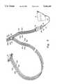
- FIG. 1is a fragmentary perspective view of a prior art multiconduit device as shown in FIG. 1 of the aforementioned U.S. Pat. No. 4,253,449;
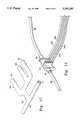
- FIG. 2is an elevational view of a prior art single conduit device as shown in FIG. 5 of the aforementioned U.S. Pat. No. 4,029,087;
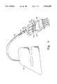
- FIG. 3is a perspective view illustrating a prior art controller for providing compressive air to the sleeves in a multiconduit system
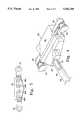
- FIG. 4is a perspective view of an adapter of this invention for insertion into the controller of the type shown in FIG. 3 to convert from multiconduit to single conduit;
- FIG. 5is an elevational view of the rear of the adapter of FIG. 4;
- FIG. 6is a perspective view of a multilumen manifold component part of the adapter of FIG. 4;
- FIG. 7is a perspective view showing the placement of the manifold of FIG. 6 within the adapter
- FIG. 8is a fragmentary perspective view of the conduit system in another embodiment of the invention.
- FIG. 9is a fragmentary perspective view of a portion of the conduit system of the embodiment of FIG. 8 enlarged for purposes of illustration;
- FIG. 10is a fragmentary perspective view of the conduit system in yet another embodiment of this invention.
- FIG. 11is a fragmentary perspective view of a portion of the conduit system of the embodiment of FIG. 10 enlarged for purposes of illustration.
- FIG. 12is a perspective view of a multilumen manifold for the adapter employed in the embodiment shown in FIGS. 10 and 11.
- the task of this inventionis to provide means for making the controllers currently in house for providing compressive air to multiconduit sleeves for applying compressive pressure to the limb useful as well with sleeves wherein a single conduit is employed to introduce air from the controller into the sleeve.
- the prior art multiconduit systemssuch as the "SCD" intermittent compression devices currently on the market comprise device 10 having a controller 12 as the source of air under pressure for applying compressive pressure to sleeves 14 and 16 around a patient's legs.
- the controller 12may be initiated in order to supply air to the legs through conduit system 18.
- conduit system 18has a first set of conduits 24a, 24b, 24c and 24d communicating with the chambers (not shown) of sleeve 24 and a second set of conduits, 26a, 26b, 26c and 26d communicating with the chambers (not shown) of the second sleeve.
- conduits 24a and 26acommunicate with the ankle chambers of the sleeves
- 24b and 26bprovide ventilating air to the chambers
- 24c and 26ccommunicate with the calf chambers of the sleeves
- conduits 24d and 26dcommunicate with the thigh chambers of the sleeves.
- the conduit system 18also has a third set of conduits, 20a, 20b, 20c and 20d in communication with controller 12 by means of connector 22.
- a T-shaped connection member 38connects the conduits of the first and second sets 24 and 26 with the third set 20 such that conduit 20a from the controller is in fluid communication exclusively with conduits 24a and 26a, conduit 20b exclusively with conduits 24b and 26b, conduit 20c exclusively with conduits 24c and 26c and conduit 20d exclusively with conduits 24d and 26d.
- FIG. 2which is derived from FIG. 5 of the aforementioned U.S. Pat. No. 4,029,087, is illustrative of the prior art compression devices utilizing a single conduit to the sleeves.
- compression device 100comprises a sleeve 110 having a foot portion 112 defining the lowermost pressure chamber 114 and separate fluid pressure chambers 116, 118 and 120 extending progressively up the leg.
- the valvespermit sequential inflation of the chambers with air initially entering the lowermost chamber 114 via conduit 126.
- FIG. 3illustrates a controller commercially available for use with the multiconduit SCD devices.
- controller 12ahas a control panel 28 for controlling the operation of the device.
- the control panelhas means for turning the device off and on, for setting the desired pressures to the respective chambers of the sleeve, for ventilating and an alarm signal in the unlikely event that the pressures within the chambers become undesirably high.
- the controllerhas a chevron-shaped recess area for releasably securing a connector for conduits 20a, 20b, 20c and 20d in fluid communication with air outlet ports 32a, b, c, and d respectively.
- FIGS. 4-7describe a particularly preferred embodiment of the invention wherein the connector means to the controller is provided with an adapter for converting from multiconduits leading to separate chambers such as would be employed with the prior art sleeves illustrated in FIG. 1 to a single conduit to be employed with sleeves such as those illustrated in FIG. 2 wherein pressurized air is introduced into the lowermost chamber and from there to successive upper chambers.
- the novel adapter 36 for the controllerhas a housing 40 with extensions 42, a rear panel 46 and a front portion 50. Mounted in extensions 42 on either side of the housing are connectors 44 of per se known structure which will lock into openings 34 (as seen in FIG. 3) to releasably secure the adapter within opening 30 of the controller. As seen in FIG. 5, the rear panel 46 of the adapter 36 is chevron-shaped to conform with the opening 30 in the controller.
- female ports 48 a, b, c, and dmate in fluid communication with male ports 32a, b, c, and d respectively of the controller.
- the adapterhas a multilumen manifold 54, having rearward lumens 56, 58 and 60 communicating with a forward lumen 52.
- Manifold 54is seated within the adapter 36 with lumens 56, 58 and 60 overlying and thereby in fluid communication with the rear portion of ports 48a, c, and d, respectively.
- the adapteris in fluid communication with exit ports 32a, b, and d, respectively of the controller.
- a single conduit 64overlies lumen 52 so that air emitted from ports 32a, c and d to inflate the chambers then passes through opening 62 in lumen 52 and then into the single conduit 64.
- the T-connector for splitting the compressed air into conduits leading to both sleeveswill be modified to provide a multilumen manifold having a single lumen to which conduits leading to the respective sleeves are in fluid communication.
- the manner of so modifying the T-connector to provide for single conduits rather than multiple conduitswill be within the expected judgment of the skilled worker in the light of the foregoing description and accordingly per se comprises no part of the present invention.
- the three ports of the controller 32 a,c and d for applying compressive air to inflate the chambersare channeled into a single conduit with no means for providing ventilation from the air emitted through port 32b.
- other means for ventilating the chambersmay be provided or, alternatively, a second conduit may be provided for communication between ventilating port 32b and the sleeve.
- the term "single conduit” or “single conduit device”refers only to the conduit system for inflating the chambers so as to provide compressive pressure to the limb and does not exclude the possibility, if so desired, of a second conduit for ventilation.
- FIGS. 8 and 9relate to another embodiment of the invention whereby conversion from a multiconduit system to a single conduit one takes place downstream between the T-connection and the sleeves.
- conduit 33 for inflating the chambers (not shown) in sleeve 16is provided with a male snap fitting 31 to secure the conduit to female fitting 29 of adapter 25.
- adapter 25is provided with multilumen manifold 54 (FIG. 6) in communication with ports 27a, c and d of the adapter. The ports 27a, b, c and d then mate with corresponding ports (not shown) in connector 23, thereby placing single lumen 33 in fluid communication with air emitted from ports 32a, c and d of the controller.
- FIGS. 10-12Yet another embodiment of the invention is illustrated in FIGS. 10-12 wherein the conversion from a multiconduit system to a single conduit one is provided by modification of the T-connector for splitting the compressed air to separate conduits leading to the two sleeves.
- T-connector 70has been modified from the previously described configuration 38 to split air coming from the controller through conduits 20a, c, and d into single conduits 66 and 68 leading to sleeves 16 and 18 respectively.
- thisis accomplished by modifying multilumen manifold 54a from the configuration of FIG. 6 so that lumen 52 communicates with lumen 65 having an opening 72 at either end for fluid communication from T-connector 70 to each of the conduits 66 and 68 leading to the sleeves.
- the present inventionpermits the clinician or other user to employ the existing in house controller for pressurized air with either sleeves provided with multiconduits leading to the individual chambers of the sleeves to sleeves having but a single conduit in communication with a source of pressurized air for inflating the chambers.
- the adaptability from one system to anotheris accomplished quickly and economically without resort to modification of the controller itself by means of the novel adapter/connectors of this invention. Accordingly, it will thus be seen that only a single controller need be provided for these alternate sleeve systems.
Landscapes
- Health & Medical Sciences (AREA)
- Epidemiology (AREA)
- Pain & Pain Management (AREA)
- Physical Education & Sports Medicine (AREA)
- Rehabilitation Therapy (AREA)
- Life Sciences & Earth Sciences (AREA)
- Animal Behavior & Ethology (AREA)
- General Health & Medical Sciences (AREA)
- Public Health (AREA)
- Veterinary Medicine (AREA)
- Massaging Devices (AREA)
Abstract
Description
Claims (4)
Priority Applications (1)
| Application Number | Priority Date | Filing Date | Title |
|---|---|---|---|
| US07/901,044US5342285A (en) | 1992-06-19 | 1992-06-19 | Adapter for devices for applying compressive pressure to the limbs |
Applications Claiming Priority (1)
| Application Number | Priority Date | Filing Date | Title |
|---|---|---|---|
| US07/901,044US5342285A (en) | 1992-06-19 | 1992-06-19 | Adapter for devices for applying compressive pressure to the limbs |
Publications (1)
| Publication Number | Publication Date |
|---|---|
| US5342285Atrue US5342285A (en) | 1994-08-30 |
Family
ID=25413507
Family Applications (1)
| Application Number | Title | Priority Date | Filing Date |
|---|---|---|---|
| US07/901,044Expired - LifetimeUS5342285A (en) | 1992-06-19 | 1992-06-19 | Adapter for devices for applying compressive pressure to the limbs |
Country Status (1)
| Country | Link |
|---|---|
| US (1) | US5342285A (en) |
Cited By (45)
| Publication number | Priority date | Publication date | Assignee | Title |
|---|---|---|---|---|
| USD363988S (en) | 1994-04-26 | 1995-11-07 | The Kendall Company | Connector for applying compressive pressure to the leg |
| USD364459S (en) | 1994-04-26 | 1995-11-21 | The Kendall Company | Connector for applying compressive pressure to the leg |
| USD364460S (en) | 1994-04-26 | 1995-11-21 | The Kendall Company | Connector for applying compressive pressure to the leg |
| USD364680S (en) | 1994-04-26 | 1995-11-28 | The Kendall Company | Connector for applying compressive pressure to the leg |
| USD369859S (en) | 1994-04-05 | 1996-05-14 | Jobst Institute, Inc. | Multi-channel conduit connector for treating deep vein thrombosis |
| USD373191S (en) | 1994-04-05 | 1996-08-27 | Jobst Institute, Inc. | Multi-channel conduit connector for treating deep vein thrombosis |
| US6149674A (en)* | 1997-11-07 | 2000-11-21 | Hill-Rom, Inc. | Patient thermal regulation system |
| US6648840B2 (en) | 1996-08-02 | 2003-11-18 | Salton, Inc. | Microcontroller based massage system |
| US6855158B2 (en) | 2001-09-11 | 2005-02-15 | Hill-Rom Services, Inc. | Thermo-regulating patient support structure |
| US7044924B1 (en) | 2000-06-02 | 2006-05-16 | Midtown Technology | Massage device |
| US20070088239A1 (en)* | 2000-06-02 | 2007-04-19 | Midtown Technology Ltd. | Inflatable massage garment |
| US20080249449A1 (en)* | 2007-04-09 | 2008-10-09 | Tyco Healthcare Group Lp | Methods of Making Compression Device with Improved Evaporation |
| US20080249447A1 (en)* | 2007-04-09 | 2008-10-09 | Tyco Healthcare Group Lp | Compression Device Having Cooling Capability |
| US7641623B2 (en) | 2003-04-11 | 2010-01-05 | Hill-Rom Services, Inc. | System for compression therapy with patient support |
| USD608006S1 (en) | 2007-04-09 | 2010-01-12 | Tyco Healthcare Group Lp | Compression device |
| US20100042028A1 (en)* | 2008-08-14 | 2010-02-18 | Albahealth, LLC | Foot wrap with inflatable bladder |
| EP2168553A1 (en)* | 2008-09-30 | 2010-03-31 | Tyco Healthcare Group LP | Tubeless Compression Device |
| US20100081974A1 (en)* | 2008-09-30 | 2010-04-01 | Tyco Healthcare Group Lp | Portable Controller Unit for a Compression Device |
| USD618358S1 (en) | 2007-04-09 | 2010-06-22 | Tyco Healthcare Group Lp | Opening in an inflatable member for a pneumatic compression device |
| US20100205739A1 (en)* | 2001-05-25 | 2010-08-19 | Gallant Dennis J | Thermoregulation equipment for patient room |
| US20110009795A1 (en)* | 2009-07-10 | 2011-01-13 | Tyco Healthcare Group Lp | Hybrid compression garmet |
| US7871387B2 (en)* | 2004-02-23 | 2011-01-18 | Tyco Healthcare Group Lp | Compression sleeve convertible in length |
| US20110201981A1 (en)* | 2010-02-12 | 2011-08-18 | Tyco Healthcare Group Lp | Compression garment assembly |
| US8021388B2 (en) | 2007-04-09 | 2011-09-20 | Tyco Healthcare Group Lp | Compression device with improved moisture evaporation |
| US8029451B2 (en) | 2005-12-12 | 2011-10-04 | Tyco Healthcare Group Lp | Compression sleeve having air conduits |
| US8029450B2 (en) | 2007-04-09 | 2011-10-04 | Tyco Healthcare Group Lp | Breathable compression device |
| US8034007B2 (en) | 2007-04-09 | 2011-10-11 | Tyco Healthcare Group Lp | Compression device with structural support features |
| US8070699B2 (en) | 2007-04-09 | 2011-12-06 | Tyco Healthcare Group Lp | Method of making compression sleeve with structural support features |
| US8114117B2 (en) | 2008-09-30 | 2012-02-14 | Tyco Healthcare Group Lp | Compression device with wear area |
| US8128584B2 (en) | 2007-04-09 | 2012-03-06 | Tyco Healthcare Group Lp | Compression device with S-shaped bladder |
| US8162861B2 (en) | 2007-04-09 | 2012-04-24 | Tyco Healthcare Group Lp | Compression device with strategic weld construction |
| US8235923B2 (en) | 2008-09-30 | 2012-08-07 | Tyco Healthcare Group Lp | Compression device with removable portion |
| CN103027833A (en)* | 2011-09-29 | 2013-04-10 | 泰科保健集团有限合伙公司 | Compression garment having sealable bladder pocket |
| US8506508B2 (en) | 2007-04-09 | 2013-08-13 | Covidien Lp | Compression device having weld seam moisture transfer |
| US8539647B2 (en) | 2005-07-26 | 2013-09-24 | Covidien Ag | Limited durability fastening for a garment |
| US8652079B2 (en) | 2010-04-02 | 2014-02-18 | Covidien Lp | Compression garment having an extension |
| US20140290795A1 (en)* | 2013-04-01 | 2014-10-02 | Caremed Supply Inc. | System for detecting and determining the type of an inflatable device being coupled with an air supply device |
| US20150216760A1 (en)* | 2014-02-04 | 2015-08-06 | Joseph Thomas Adams | Multi-Port Connection and Multi-Port Multiple Outlet Manifold |
| US9205021B2 (en) | 2012-06-18 | 2015-12-08 | Covidien Lp | Compression system with vent cooling feature |
| US9737454B2 (en) | 2012-03-02 | 2017-08-22 | Hill-Rom Services, Inc. | Sequential compression therapy compliance monitoring systems and methods |
| US10507158B2 (en) | 2016-02-18 | 2019-12-17 | Hill-Rom Services, Inc. | Patient support apparatus having an integrated limb compression device |
| US10751221B2 (en) | 2010-09-14 | 2020-08-25 | Kpr U.S., Llc | Compression sleeve with improved position retention |
| US20220168171A1 (en)* | 2019-03-08 | 2022-06-02 | Medi Usa, L.P. | Pneumatic compression systems and compression treatment methods |
| US20220409474A1 (en)* | 2021-06-23 | 2022-12-29 | Sunmedix Co.,Ltd | Movable limb compression and circulation apparatus |
| US11564859B2 (en)* | 2017-11-21 | 2023-01-31 | Maxstar Industrial Co., Ltd. | Shorts-type air pressure massager |
Citations (6)
| Publication number | Priority date | Publication date | Assignee | Title |
|---|---|---|---|---|
| US1607096A (en)* | 1923-04-28 | 1926-11-16 | Adolph Mueller Trustee | Faucet connection |
| US4029087A (en)* | 1975-10-28 | 1977-06-14 | The Kendall Company | Extremity compression device |
| US4280485A (en)* | 1980-04-11 | 1981-07-28 | The Kendall Company | Compression device with simulator |
| US4628730A (en)* | 1984-11-01 | 1986-12-16 | Maguire James V | Equal fluid flow distribution system and manifold |
| US4718467A (en)* | 1986-05-30 | 1988-01-12 | Baxter Travenol Laboratories, Inc. | Pumping module arrangement and manifold |
| US5167227A (en)* | 1991-08-15 | 1992-12-01 | Meserlian Sarkis B | Apparatus for massaging and/or controllably supporting the legs of a horse |
- 1992
- 1992-06-19USUS07/901,044patent/US5342285A/ennot_activeExpired - Lifetime
Patent Citations (6)
| Publication number | Priority date | Publication date | Assignee | Title |
|---|---|---|---|---|
| US1607096A (en)* | 1923-04-28 | 1926-11-16 | Adolph Mueller Trustee | Faucet connection |
| US4029087A (en)* | 1975-10-28 | 1977-06-14 | The Kendall Company | Extremity compression device |
| US4280485A (en)* | 1980-04-11 | 1981-07-28 | The Kendall Company | Compression device with simulator |
| US4628730A (en)* | 1984-11-01 | 1986-12-16 | Maguire James V | Equal fluid flow distribution system and manifold |
| US4718467A (en)* | 1986-05-30 | 1988-01-12 | Baxter Travenol Laboratories, Inc. | Pumping module arrangement and manifold |
| US5167227A (en)* | 1991-08-15 | 1992-12-01 | Meserlian Sarkis B | Apparatus for massaging and/or controllably supporting the legs of a horse |
Cited By (80)
| Publication number | Priority date | Publication date | Assignee | Title |
|---|---|---|---|---|
| USD369859S (en) | 1994-04-05 | 1996-05-14 | Jobst Institute, Inc. | Multi-channel conduit connector for treating deep vein thrombosis |
| USD373191S (en) | 1994-04-05 | 1996-08-27 | Jobst Institute, Inc. | Multi-channel conduit connector for treating deep vein thrombosis |
| USD363988S (en) | 1994-04-26 | 1995-11-07 | The Kendall Company | Connector for applying compressive pressure to the leg |
| USD364459S (en) | 1994-04-26 | 1995-11-21 | The Kendall Company | Connector for applying compressive pressure to the leg |
| USD364460S (en) | 1994-04-26 | 1995-11-21 | The Kendall Company | Connector for applying compressive pressure to the leg |
| USD364680S (en) | 1994-04-26 | 1995-11-28 | The Kendall Company | Connector for applying compressive pressure to the leg |
| US6648840B2 (en) | 1996-08-02 | 2003-11-18 | Salton, Inc. | Microcontroller based massage system |
| US6149674A (en)* | 1997-11-07 | 2000-11-21 | Hill-Rom, Inc. | Patient thermal regulation system |
| US20070088239A1 (en)* | 2000-06-02 | 2007-04-19 | Midtown Technology Ltd. | Inflatable massage garment |
| US7044924B1 (en) | 2000-06-02 | 2006-05-16 | Midtown Technology | Massage device |
| US7771376B2 (en) | 2000-06-02 | 2010-08-10 | Midtown Technology Ltd. | Inflatable massage garment |
| US20100205739A1 (en)* | 2001-05-25 | 2010-08-19 | Gallant Dennis J | Thermoregulation equipment for patient room |
| US8499503B2 (en) | 2001-05-25 | 2013-08-06 | Hill-Rom Services, Inc. | Thermoregulation equipment for patient room |
| US8683750B2 (en) | 2001-05-25 | 2014-04-01 | Hill-Rom Services, Inc. | Architectural headwall cabinet for storing a lift device |
| US6855158B2 (en) | 2001-09-11 | 2005-02-15 | Hill-Rom Services, Inc. | Thermo-regulating patient support structure |
| US9220655B2 (en) | 2003-04-11 | 2015-12-29 | Hill-Rom Services, Inc. | System for compression therapy |
| US7641623B2 (en) | 2003-04-11 | 2010-01-05 | Hill-Rom Services, Inc. | System for compression therapy with patient support |
| US7871387B2 (en)* | 2004-02-23 | 2011-01-18 | Tyco Healthcare Group Lp | Compression sleeve convertible in length |
| US9364037B2 (en) | 2005-07-26 | 2016-06-14 | Covidien Ag | Limited durability fastening for a garment |
| US8539647B2 (en) | 2005-07-26 | 2013-09-24 | Covidien Ag | Limited durability fastening for a garment |
| US8029451B2 (en) | 2005-12-12 | 2011-10-04 | Tyco Healthcare Group Lp | Compression sleeve having air conduits |
| US8079970B2 (en) | 2005-12-12 | 2011-12-20 | Tyco Healthcare Group Lp | Compression sleeve having air conduits formed by a textured surface |
| US20080249447A1 (en)* | 2007-04-09 | 2008-10-09 | Tyco Healthcare Group Lp | Compression Device Having Cooling Capability |
| US8109892B2 (en) | 2007-04-09 | 2012-02-07 | Tyco Healthcare Group Lp | Methods of making compression device with improved evaporation |
| US9387146B2 (en) | 2007-04-09 | 2016-07-12 | Covidien Lp | Compression device having weld seam moisture transfer |
| US9808395B2 (en) | 2007-04-09 | 2017-11-07 | Covidien Lp | Compression device having cooling capability |
| US9114052B2 (en) | 2007-04-09 | 2015-08-25 | Covidien Lp | Compression device with strategic weld construction |
| US8016779B2 (en) | 2007-04-09 | 2011-09-13 | Tyco Healthcare Group Lp | Compression device having cooling capability |
| US8016778B2 (en) | 2007-04-09 | 2011-09-13 | Tyco Healthcare Group Lp | Compression device with improved moisture evaporation |
| US8021388B2 (en) | 2007-04-09 | 2011-09-20 | Tyco Healthcare Group Lp | Compression device with improved moisture evaporation |
| US20080249449A1 (en)* | 2007-04-09 | 2008-10-09 | Tyco Healthcare Group Lp | Methods of Making Compression Device with Improved Evaporation |
| US8029450B2 (en) | 2007-04-09 | 2011-10-04 | Tyco Healthcare Group Lp | Breathable compression device |
| US8034007B2 (en) | 2007-04-09 | 2011-10-11 | Tyco Healthcare Group Lp | Compression device with structural support features |
| US8070699B2 (en) | 2007-04-09 | 2011-12-06 | Tyco Healthcare Group Lp | Method of making compression sleeve with structural support features |
| US8622942B2 (en) | 2007-04-09 | 2014-01-07 | Covidien Lp | Method of making compression sleeve with structural support features |
| USD618358S1 (en) | 2007-04-09 | 2010-06-22 | Tyco Healthcare Group Lp | Opening in an inflatable member for a pneumatic compression device |
| US9107793B2 (en) | 2007-04-09 | 2015-08-18 | Covidien Lp | Compression device with structural support features |
| US8128584B2 (en) | 2007-04-09 | 2012-03-06 | Tyco Healthcare Group Lp | Compression device with S-shaped bladder |
| US8162861B2 (en) | 2007-04-09 | 2012-04-24 | Tyco Healthcare Group Lp | Compression device with strategic weld construction |
| US9084713B2 (en) | 2007-04-09 | 2015-07-21 | Covidien Lp | Compression device having cooling capability |
| US8992449B2 (en) | 2007-04-09 | 2015-03-31 | Covidien Lp | Method of making compression sleeve with structural support features |
| US8740828B2 (en) | 2007-04-09 | 2014-06-03 | Covidien Lp | Compression device with improved moisture evaporation |
| US8721575B2 (en) | 2007-04-09 | 2014-05-13 | Covidien Lp | Compression device with s-shaped bladder |
| USD608006S1 (en) | 2007-04-09 | 2010-01-12 | Tyco Healthcare Group Lp | Compression device |
| US8597215B2 (en) | 2007-04-09 | 2013-12-03 | Covidien Lp | Compression device with structural support features |
| US8506508B2 (en) | 2007-04-09 | 2013-08-13 | Covidien Lp | Compression device having weld seam moisture transfer |
| US10137052B2 (en) | 2008-04-07 | 2018-11-27 | Kpr U.S., Llc | Compression device with wear area |
| US20100042028A1 (en)* | 2008-08-14 | 2010-02-18 | Albahealth, LLC | Foot wrap with inflatable bladder |
| EP2174633A1 (en)* | 2008-09-30 | 2010-04-14 | Tyco Healthcare Group LP | Tubeless Compression Device |
| US8235923B2 (en) | 2008-09-30 | 2012-08-07 | Tyco Healthcare Group Lp | Compression device with removable portion |
| US8535253B2 (en) | 2008-09-30 | 2013-09-17 | Covidien Lp | Tubeless compression device |
| US8632840B2 (en) | 2008-09-30 | 2014-01-21 | Covidien Lp | Compression device with wear area |
| EP2168553A1 (en)* | 2008-09-30 | 2010-03-31 | Tyco Healthcare Group LP | Tubeless Compression Device |
| US20100081974A1 (en)* | 2008-09-30 | 2010-04-01 | Tyco Healthcare Group Lp | Portable Controller Unit for a Compression Device |
| US9433532B2 (en) | 2008-09-30 | 2016-09-06 | Covidien Lp | Tubeless compression device |
| US8114117B2 (en) | 2008-09-30 | 2012-02-14 | Tyco Healthcare Group Lp | Compression device with wear area |
| AU2009217400B2 (en)* | 2008-09-30 | 2013-10-24 | Covidien Lp | Tubeless compression device |
| US20100081977A1 (en)* | 2008-09-30 | 2010-04-01 | Tyco Healthcare Group Lp | Tubeless Compression Device |
| US8177734B2 (en) | 2008-09-30 | 2012-05-15 | Tyco Healthcare Group Lp | Portable controller unit for a compression device |
| CN101711720A (en)* | 2008-09-30 | 2010-05-26 | 泰科保健集团有限合伙公司 | Tubeless compression device |
| US8162869B2 (en) | 2009-07-10 | 2012-04-24 | Tyco Healthcare Group Lp | Hybrid compression garmet |
| US20110009795A1 (en)* | 2009-07-10 | 2011-01-13 | Tyco Healthcare Group Lp | Hybrid compression garmet |
| US8801643B2 (en) | 2010-02-12 | 2014-08-12 | Covidien Lp | Compression garment assembly |
| US20110201981A1 (en)* | 2010-02-12 | 2011-08-18 | Tyco Healthcare Group Lp | Compression garment assembly |
| US8394043B2 (en) | 2010-02-12 | 2013-03-12 | Covidien Lp | Compression garment assembly |
| US8652079B2 (en) | 2010-04-02 | 2014-02-18 | Covidien Lp | Compression garment having an extension |
| US10751221B2 (en) | 2010-09-14 | 2020-08-25 | Kpr U.S., Llc | Compression sleeve with improved position retention |
| CN103027833A (en)* | 2011-09-29 | 2013-04-10 | 泰科保健集团有限合伙公司 | Compression garment having sealable bladder pocket |
| US10943678B2 (en) | 2012-03-02 | 2021-03-09 | Hill-Rom Services, Inc. | Sequential compression therapy compliance monitoring systems and methods |
| US9737454B2 (en) | 2012-03-02 | 2017-08-22 | Hill-Rom Services, Inc. | Sequential compression therapy compliance monitoring systems and methods |
| US9205021B2 (en) | 2012-06-18 | 2015-12-08 | Covidien Lp | Compression system with vent cooling feature |
| US20140290795A1 (en)* | 2013-04-01 | 2014-10-02 | Caremed Supply Inc. | System for detecting and determining the type of an inflatable device being coupled with an air supply device |
| US9316358B2 (en)* | 2013-04-01 | 2016-04-19 | Caremed Supply Inc. | System for detecting and determining the type of an inflatable device being coupled with an air supply device |
| US20150216760A1 (en)* | 2014-02-04 | 2015-08-06 | Joseph Thomas Adams | Multi-Port Connection and Multi-Port Multiple Outlet Manifold |
| US10507158B2 (en) | 2016-02-18 | 2019-12-17 | Hill-Rom Services, Inc. | Patient support apparatus having an integrated limb compression device |
| US10952920B2 (en) | 2016-02-18 | 2021-03-23 | Hill-Rom Services, Inc. | Patient support apparatus having an integrated limb compression device |
| US11564859B2 (en)* | 2017-11-21 | 2023-01-31 | Maxstar Industrial Co., Ltd. | Shorts-type air pressure massager |
| US20220168171A1 (en)* | 2019-03-08 | 2022-06-02 | Medi Usa, L.P. | Pneumatic compression systems and compression treatment methods |
| US12383455B2 (en)* | 2019-03-08 | 2025-08-12 | Medi Usa, L.P. | Pneumatic compression systems and compression treatment methods |
| US20220409474A1 (en)* | 2021-06-23 | 2022-12-29 | Sunmedix Co.,Ltd | Movable limb compression and circulation apparatus |
Similar Documents
| Publication | Publication Date | Title |
|---|---|---|
| US5342285A (en) | Adapter for devices for applying compressive pressure to the limbs | |
| US4320746A (en) | Compression device with improved pressure control | |
| US5052377A (en) | Apparatus for massaging the body by cyclic pressure, and constituent means | |
| EP1104521B1 (en) | Fluidic connector | |
| US4753236A (en) | Temporary anastomotic device | |
| US5575762A (en) | Gradient sequential compression system and method for reducing the occurrence of deep vein thrombosis | |
| US4280485A (en) | Compression device with simulator | |
| US3908642A (en) | Means for aerating and applying air pulsations within casts | |
| US4721109A (en) | Temporary anastomotic device | |
| WO2001080927A3 (en) | Supplemental blood pump, methods and systems for supplementing blood flow | |
| US20040106884A1 (en) | Gradient sequential compression system for preventing deep vein thrombosis | |
| WO1998031405A3 (en) | Drug delivery system | |
| WO1997033532A3 (en) | Endoluminal prostheses and therapies for multiple-branch body lumen systems | |
| AU4007895A (en) | Systems and methods for promoting tissue growth | |
| CA2499107A1 (en) | Multi-pressure biocompatible agent delivery device and method | |
| WO2000021461A3 (en) | Delivering a conduit into a heart wall to place a coronary vessel in communication with a heart chamber and removing tissue from the vessel or heart wall to facilitate such communication | |
| JPH0329656A (en) | Apparatus for applying compression to subject's limb | |
| CA2177144A1 (en) | Percutaneous prosthetic graft | |
| AU2004245124A1 (en) | Device and method for low pressure compresssion and valve for use in the system | |
| MXPA98002813A (en) | Catheter, in particular for peritoneal dialysis. | |
| AU9171598A (en) | Guiding element for balloon catheters or the like and method of use | |
| AU2462597A (en) | Multichannel catheter | |
| EP0840018A3 (en) | Pilot 5-port transfer valve | |
| US8591439B1 (en) | Extended term patient resuscitation/ventilation system | |
| WO2002024108A3 (en) | A device and an introducer for providing a supplemental flow of blood |
Legal Events
| Date | Code | Title | Description |
|---|---|---|---|
| AS | Assignment | Owner name:KENDALL COMPANY, THE, MASSACHUSETTS Free format text:ASSIGNMENT OF ASSIGNORS INTEREST.;ASSIGNOR:DYE, JOHN F.;REEL/FRAME:006203/0360 Effective date:19920611 | |
| AS | Assignment | Owner name:CHEMICAL BANK, AS AGENT Free format text:SECURITY INTEREST;ASSIGNOR:KENDALL COMPANY, THE A CORP. OF DE;REEL/FRAME:006325/0009 Effective date:19920707 | |
| STCF | Information on status: patent grant | Free format text:PATENTED CASE | |
| AS | Assignment | Owner name:KENDALL COMPANY, THE, MASSACHUSETTS Free format text:RELEASE OF SECURITY INTEREST;ASSIGNOR:CHEMICAL BANK (THE SUCCESSOR BY MERGER WITH MANUFACTURER'S HANOVER TRUST COMPANY);REEL/FRAME:007644/0328 Effective date:19950102 | |
| FEPP | Fee payment procedure | Free format text:PAYOR NUMBER ASSIGNED (ORIGINAL EVENT CODE: ASPN); ENTITY STATUS OF PATENT OWNER: LARGE ENTITY | |
| FPAY | Fee payment | Year of fee payment:4 | |
| FPAY | Fee payment | Year of fee payment:8 | |
| FPAY | Fee payment | Year of fee payment:12 |