US5341768A - Apparatus for frictionally heating liquid - Google Patents
Apparatus for frictionally heating liquidDownload PDFInfo
- Publication number
- US5341768A US5341768AUS08/124,019US12401993AUS5341768AUS 5341768 AUS5341768 AUS 5341768AUS 12401993 AUS12401993 AUS 12401993AUS 5341768 AUS5341768 AUS 5341768A
- Authority
- US
- United States
- Prior art keywords
- rotor
- passages
- outlets
- housing
- liquid
- Prior art date
- Legal status (The legal status is an assumption and is not a legal conclusion. Google has not performed a legal analysis and makes no representation as to the accuracy of the status listed.)
- Expired - Lifetime
Links
- 239000007788liquidSubstances0.000titleclaimsabstractdescription57
- 238000010438heat treatmentMethods0.000titleclaimsabstractdescription10
- 238000010008shearingMethods0.000claimsdescription3
- 230000000295complement effectEffects0.000claimsdescription2
- 239000012530fluidSubstances0.000claimsdescription2
- 238000005086pumpingMethods0.000description3
- 230000002093peripheral effectEffects0.000description2
- 230000007423decreaseEffects0.000description1
- 230000001419dependent effectEffects0.000description1
- 230000000694effectsEffects0.000description1
- 230000001939inductive effectEffects0.000description1
- 238000012986modificationMethods0.000description1
- 230000004048modificationEffects0.000description1
Images


Classifications
- F—MECHANICAL ENGINEERING; LIGHTING; HEATING; WEAPONS; BLASTING
- F24—HEATING; RANGES; VENTILATING
- F24V—COLLECTION, PRODUCTION OR USE OF HEAT NOT OTHERWISE PROVIDED FOR
- F24V40/00—Production or use of heat resulting from internal friction of moving fluids or from friction between fluids and moving bodies
Definitions
- This inventionrelates to liquid heating apparatus and more particularly to apparatus which heats liquid by friction.
- the broad object of the present inventionis to provide a heater for heating liquid by friction but with enhanced efficiency over prior systems.
- the inventionprovides a single heating rotor having a pair of central inlet cavities on opposite sides of a central web.
- a plurality of passages, say 24, having restrictive orifices therein,are arranged in the rotor angularly related to its axis of rotation in a manner inducing them to impel liquid with great centrifugal force through the restricted orifices thereby frictionally heating the liquid.
- the passageshave outlets circumferentially spaced on the periphery of the rotor and lying in a plane bisecting the rotor.
- the rotoris rotated by an outside power source in a housing filled with liquid and having a plurality of outlets also lying in the plane bisecting the rotor.
- Alternate rotor passagessay every other one of 24 or 12, have inlets connecting alternate outlets with one inlet cavity.
- the other alternate passagesalso 12 in number, have inlets connecting the other alternate outlets to the second inlet cavity.
- One of the outlets from the housingleads to a heat utilization device, say, a heat exchanger.
- the pumping capacity of the rotorexceeds the capacity of the outlet leading to the heat utilization device.
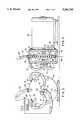
- FIG. 1is a vertical elevation, partly broken away of one side of a rotor constructed in accordance with the invention, the opposite side of the rotor being essentially a mirror image of the rotor as shown in FIG. 1;
- FIG. 2is a side elevation of the rotor of FIG. 1;
- FIG. 3is an end elevational view on a reduced scale of a rotor housing incorporating the invention
- FIG. 4is a side view partly in section and partly in elevation of the assembly of FIG. 3 and including a driving motor;
- FIG. 5is an end view of the rotor and housing with parts omitted, including a side of the rotor housing, illustrating a friction-increasing liquid shearing ramp which may be used with the rotor of the invention.
- FIG. 6is a vertical cross sectional view, partly schematic, illustrating the arrangement of liquid passages within the rotor.
- the liquid heating apparatus of the inventioncomprises an impeller or rotor 10, broadly designated by the numeral 10, designed to be disposed within a housing 12, (FIGS. 3 and 4) defining a reservoir for a heat transfer liquid.
- the rotor 10is rotatable about an axis of rotation 14 in a predetermined direction as indicated by the arrow 16.
- the rotor 10comprises axially spaced front and rear annular face members 18, 20 each having radially spaced inner and outer edges 22, 24. Radially spaced inner and outer cylindrical surfaces 26, 28 of predetermined axial width join the respective inner and outer edges 22, 24 of the face members 18, 20.
- a web 30 having an axial width substantially less than the axial width of the inner cylindrical surface 26is fixed to the surface 26 midway of the width thereof, the web 30 being provided with a central collar 32 for receiving a rotor driving shaft 34.
- the web 30 with the inner cylindrical surface 26 on either side of the webdefine first and second annular inlet cavities 36, 38 in the rotor.
- a plurality of fluid transfer passages 40, 42are provided in the rotor 10, which for purposes of illustration, may total 24 one-half of the total number, say passages 40 numbering 12, lead to the first inlet cavity 36 and the remaining passages 42 lead to the second inlet cavity 38.
- the passages 40, 42have outlets 40a, 42a lie symmetrically in common plane 44 bisecting the rotor end all of which are equally circumferentially spaced around and opening through the outer cylindrical surface 28 as should be clear in FIGS. 2.
- Alternate ones of the passages, say the passages 40have inlets 40b opening through the inner cylindrical surface 26 on one side of the web 30 to connect the alternate ones of the outlets 40a with the first inlet cavity 36.
- the other alternate ones of the passage 42have inlets 42b opening through the inner cylindrical surface 26 on the other side of the web 30 to connect said other alternate outlets 42a with the second inlet cavity 38.
- the inventionis dependent, in part, on the ability of the rotor to pump past its periphery an amount of liquid in excess of a receiver's capacity to accept the quantity pumped, as will become apparent hereinafter.
- a large number of liquid transfer passages 40, 42are required in the rotor and though there is space on the peripheral cylindrical surface 28 for the passage outlets 40a, 42a there is not sufficient space on the inner peripheral surface 26 for all the inlets 40b, 42b.
- the respective alternate passages 40, 42are alternately axially sloped as shown in FIG. 6 so that their respective inlets 40b, 42b are located in the respective inlet cavities 36, 38 whereas their outlets 40a, 40b lie symmetrically in the plane 44 bisecting the rotor, see FIG. 4.
- each passage 40, 42is provided along its length, preferably at its outlets, with a restricted orifice 46 which may be formed in a threaded insert 50, only one such insert being shown in FIG. 1 though all passages have identical inserts.
- the rotor 10is disposed within the housing 12 with means, such as the motor 52 being provided to rotate the rotor 10 through shaft 34 in the predetermined direction 16.
- the housinghas a pair of axially spaced end walls 54, 56 joined by a cylindrical side wall 58 whose internal diameter is substantially complementary to the diameter of the rotor 10.
- outlets 60, 62, 64through the side wall 58.
- inlets 68, 70, 72are provided through at least one end wall, in this case end wall 54 though, should the drive motor 52 be spaced to the right of rotor housing 12, one or more inlets could also be located in end wall 56.
- the number of inlets 68, 70, 72are equal in number to the outlets 60, 62, 64 and at least one of the inlets, say inlet 70, is connected by a pipe 73 to the outlet of the heat utilization device 66, with by-pass passages 76, 78 connecting the other outlets 60, 64 with corresponding inlets 68, 72. There could be additional by-passages.
- the outer diameter of the rotor 10is less than the inner diameter of the housing 12 to provide an annular space 78 between the housing and rotor.
- At least one wedge shaped ramp 80is fixed to the housing in the space 78 and has an edge 82 terminating in close adjacency to the periphery of the rotor whereby the ramp further frictionally heats the liquid through shearing action as liquid is impelled through the passages 40, 42 in the rotor.
- the ramp's wedge shapediverges in a direction opposite to the predetermined direction of rotation of the rotor but it is within the purview of the invention for the wedge shape to diverge in the direction of rotor rotation.
Landscapes
- Engineering & Computer Science (AREA)
- Physics & Mathematics (AREA)
- Thermal Sciences (AREA)
- Chemical & Material Sciences (AREA)
- Combustion & Propulsion (AREA)
- Mechanical Engineering (AREA)
- General Engineering & Computer Science (AREA)
- Structures Of Non-Positive Displacement Pumps (AREA)
Abstract
Description
Claims (10)
Priority Applications (1)
| Application Number | Priority Date | Filing Date | Title |
|---|---|---|---|
| US08/124,019US5341768A (en) | 1993-09-21 | 1993-09-21 | Apparatus for frictionally heating liquid |
Applications Claiming Priority (1)
| Application Number | Priority Date | Filing Date | Title |
|---|---|---|---|
| US08/124,019US5341768A (en) | 1993-09-21 | 1993-09-21 | Apparatus for frictionally heating liquid |
Publications (1)
| Publication Number | Publication Date |
|---|---|
| US5341768Atrue US5341768A (en) | 1994-08-30 |
Family
ID=22412286
Family Applications (1)
| Application Number | Title | Priority Date | Filing Date |
|---|---|---|---|
| US08/124,019Expired - LifetimeUS5341768A (en) | 1993-09-21 | 1993-09-21 | Apparatus for frictionally heating liquid |
Country Status (1)
| Country | Link |
|---|---|
| US (1) | US5341768A (en) |
Cited By (43)
| Publication number | Priority date | Publication date | Assignee | Title |
|---|---|---|---|---|
| US5419306A (en)* | 1994-10-05 | 1995-05-30 | Huffman; Michael T. | Apparatus for heating liquids |
| FR2751056A1 (en)* | 1996-07-15 | 1998-01-16 | Toyoda Automatic Loom Works | VISCOUS FLUID HEATING DEVICE |
| EP0821209A3 (en)* | 1996-07-23 | 1998-05-20 | Kabushiki Kaisha Toyoda Jidoshokki Seisakusho | Viscous fluid type heat generator with heat generation regulating performance |
| US5906055A (en)* | 1993-07-19 | 1999-05-25 | Grenci; Charles | Heat generation through mechanical molecular gas agitation |
| US6016798A (en)* | 1995-04-18 | 2000-01-25 | Advanced Molecular Technologies Llc | Method of heating a liquid and a device therefor |
| US6019499A (en)* | 1995-04-18 | 2000-02-01 | Advanced Molecular Technologies, Llc | Method of conditioning hydrocarbon liquids and an apparatus for carrying out the method |
| US20040062647A1 (en)* | 2002-09-26 | 2004-04-01 | Garrett Norman H. | Roto-dynamic fluidic systems |
| US20040194775A1 (en)* | 2003-04-02 | 2004-10-07 | Thoma Christian Helmut | Apparatus and method for heating fluids |
| KR100489760B1 (en)* | 2002-06-24 | 2005-05-16 | 김원무 | Heat generating Device using Rotatory force |
| RU2255267C2 (en)* | 2003-06-27 | 2005-06-27 | Лисняк Станислав Афанасьевич | Heater for fluid |
| US20050263607A1 (en)* | 2004-05-28 | 2005-12-01 | Christian Thoma | Heat generator |
| RU2334177C2 (en)* | 2005-04-13 | 2008-09-20 | Евгений Георгиевич Порсев | Cavitational heat generator |
| US20090191065A1 (en)* | 2006-08-26 | 2009-07-30 | Ksb Aktiengesellschaft | Feed Pump |
| US7614367B1 (en) | 2006-05-15 | 2009-11-10 | F. Alan Frick | Method and apparatus for heating, concentrating and evaporating fluid |
| US7654728B2 (en) | 1997-10-24 | 2010-02-02 | Revalesio Corporation | System and method for therapeutic application of dissolved oxygen |
| US20100059600A1 (en)* | 2008-09-10 | 2010-03-11 | Vortex Co., Ltd. | High efficiency heater using spatial energy |
| US7726331B1 (en) | 2007-05-23 | 2010-06-01 | Giese Gregory C | Modular fluid handling device II |
| US20100154395A1 (en)* | 2006-04-24 | 2010-06-24 | Franklin Alan Frick | Methods and apparatuses for heating, concentrating and evaporating fluid |
| US7770814B2 (en) | 1997-10-24 | 2010-08-10 | Revalesio Corporation | System and method for irrigating with aerated water |
| US7806584B2 (en) | 1997-10-24 | 2010-10-05 | Revalesio Corporation | Diffuser/emulsifier |
| US7832920B2 (en) | 2006-10-25 | 2010-11-16 | Revalesio Corporation | Mixing device for creating an output mixture by mixing a first material and a second material |
| US7887698B2 (en) | 1997-10-24 | 2011-02-15 | Revalesio Corporation | Diffuser/emulsifier for aquaculture applications |
| US8445546B2 (en) | 2006-10-25 | 2013-05-21 | Revalesio Corporation | Electrokinetically-altered fluids comprising charge-stabilized gas-containing nanostructures |
| RU2495337C2 (en)* | 2011-12-16 | 2013-10-10 | Общество с ограниченной ответственностью Научно-производственная фирма "Свет.Вода.Тепло-М" | Electrically driven pump-sealed rotary heat generator |
| US8591957B2 (en) | 2006-10-25 | 2013-11-26 | Revalesio Corporation | Methods of therapeutic treatment of eyes and other human tissues using an oxygen-enriched solution |
| US8609148B2 (en) | 2006-10-25 | 2013-12-17 | Revalesio Corporation | Methods of therapeutic treatment of eyes |
| US8617616B2 (en) | 2006-10-25 | 2013-12-31 | Revalesio Corporation | Methods of wound care and treatment |
| US8784898B2 (en) | 2006-10-25 | 2014-07-22 | Revalesio Corporation | Methods of wound care and treatment |
| US8784897B2 (en) | 2006-10-25 | 2014-07-22 | Revalesio Corporation | Methods of therapeutic treatment of eyes |
| US8815292B2 (en) | 2009-04-27 | 2014-08-26 | Revalesio Corporation | Compositions and methods for treating insulin resistance and diabetes mellitus |
| RU2534198C2 (en)* | 2012-12-26 | 2014-11-27 | Юрий Семенович Потапов | Heat energy generation method and device |
| US8980325B2 (en) | 2008-05-01 | 2015-03-17 | Revalesio Corporation | Compositions and methods for treating digestive disorders |
| US9198929B2 (en) | 2010-05-07 | 2015-12-01 | Revalesio Corporation | Compositions and methods for enhancing physiological performance and recovery time |
| US9370194B2 (en)* | 2013-06-05 | 2016-06-21 | Smith-Root, Inc. | Method and apparatus for slaughtering of fish |
| US20160265813A1 (en)* | 2015-03-12 | 2016-09-15 | Tyler Charles Krumm | Flameless Friction Heater |
| US9492404B2 (en) | 2010-08-12 | 2016-11-15 | Revalesio Corporation | Compositions and methods for treatment of taupathy |
| US9523090B2 (en) | 2007-10-25 | 2016-12-20 | Revalesio Corporation | Compositions and methods for treating inflammation |
| US9745567B2 (en) | 2008-04-28 | 2017-08-29 | Revalesio Corporation | Compositions and methods for treating multiple sclerosis |
| US9776102B2 (en) | 2006-04-24 | 2017-10-03 | Phoenix Caliente Llc | Methods and systems for heating and manipulating fluids |
| US10039996B2 (en) | 2006-04-24 | 2018-08-07 | Phoenix Callente LLC | Methods and systems for heating and manipulating fluids |
| US10125359B2 (en) | 2007-10-25 | 2018-11-13 | Revalesio Corporation | Compositions and methods for treating inflammation |
| US10145586B2 (en) | 2015-01-20 | 2018-12-04 | Wacker Neuson Production Americas Llc | Flameless heater |
| US20220389840A1 (en)* | 2021-06-03 | 2022-12-08 | Howard Purdum | Reaction turbine operating on condensing vapors |
Citations (13)
| Publication number | Priority date | Publication date | Assignee | Title |
|---|---|---|---|---|
| US3333771A (en)* | 1963-09-13 | 1967-08-01 | Scandura Inc | Heating means |
| US4143639A (en)* | 1977-08-22 | 1979-03-13 | Frenette Eugene J | Friction heat space heater |
| US4256085A (en)* | 1979-03-02 | 1981-03-17 | Line Howard C | Method and system for generating heat |
| US4277020A (en)* | 1979-04-30 | 1981-07-07 | General Industries, Inc. | Fluid friction heater |
| US4357931A (en)* | 1980-09-11 | 1982-11-09 | Wolpert Kenneth R | Flameless heat source |
| US4372254A (en)* | 1981-01-23 | 1983-02-08 | Edmund Hildebrandt | Hydraulic heat generator |
| US4424797A (en)* | 1981-10-13 | 1984-01-10 | Eugene Perkins | Heating device |
| US4483277A (en)* | 1983-06-02 | 1984-11-20 | Perkins Eugene W | Superheated liquid heating system |
| US4501231A (en)* | 1983-06-02 | 1985-02-26 | Perkins Eugene W | Heating system with liquid pre-heating |
| US4651681A (en)* | 1981-10-13 | 1987-03-24 | Perkins Eugene W | Heating system using a liquid heater as the source of heat |
| US4779575A (en)* | 1987-08-04 | 1988-10-25 | Perkins Eugene W | Liquid friction heating apparatus |
| US4798176A (en)* | 1987-08-04 | 1989-01-17 | Perkins Eugene W | Apparatus for frictionally heating liquid |
| US5279262A (en)* | 1992-06-04 | 1994-01-18 | Muehleck Norman J | Mechanical liquid vaporizing waterbrake |
- 1993
- 1993-09-21USUS08/124,019patent/US5341768A/ennot_activeExpired - Lifetime
Patent Citations (13)
| Publication number | Priority date | Publication date | Assignee | Title |
|---|---|---|---|---|
| US3333771A (en)* | 1963-09-13 | 1967-08-01 | Scandura Inc | Heating means |
| US4143639A (en)* | 1977-08-22 | 1979-03-13 | Frenette Eugene J | Friction heat space heater |
| US4256085A (en)* | 1979-03-02 | 1981-03-17 | Line Howard C | Method and system for generating heat |
| US4277020A (en)* | 1979-04-30 | 1981-07-07 | General Industries, Inc. | Fluid friction heater |
| US4357931A (en)* | 1980-09-11 | 1982-11-09 | Wolpert Kenneth R | Flameless heat source |
| US4372254A (en)* | 1981-01-23 | 1983-02-08 | Edmund Hildebrandt | Hydraulic heat generator |
| US4424797A (en)* | 1981-10-13 | 1984-01-10 | Eugene Perkins | Heating device |
| US4651681A (en)* | 1981-10-13 | 1987-03-24 | Perkins Eugene W | Heating system using a liquid heater as the source of heat |
| US4483277A (en)* | 1983-06-02 | 1984-11-20 | Perkins Eugene W | Superheated liquid heating system |
| US4501231A (en)* | 1983-06-02 | 1985-02-26 | Perkins Eugene W | Heating system with liquid pre-heating |
| US4779575A (en)* | 1987-08-04 | 1988-10-25 | Perkins Eugene W | Liquid friction heating apparatus |
| US4798176A (en)* | 1987-08-04 | 1989-01-17 | Perkins Eugene W | Apparatus for frictionally heating liquid |
| US5279262A (en)* | 1992-06-04 | 1994-01-18 | Muehleck Norman J | Mechanical liquid vaporizing waterbrake |
Cited By (69)
| Publication number | Priority date | Publication date | Assignee | Title |
|---|---|---|---|---|
| US5979075A (en)* | 1993-07-19 | 1999-11-09 | Grenci; Charles | Heat generation through mechanical molecular gas agitation |
| US6049997A (en)* | 1993-07-19 | 2000-04-18 | Grenci; Charles | Heat generation through mechanical molecular gas agitation |
| US5906055A (en)* | 1993-07-19 | 1999-05-25 | Grenci; Charles | Heat generation through mechanical molecular gas agitation |
| US5419306A (en)* | 1994-10-05 | 1995-05-30 | Huffman; Michael T. | Apparatus for heating liquids |
| US6019499A (en)* | 1995-04-18 | 2000-02-01 | Advanced Molecular Technologies, Llc | Method of conditioning hydrocarbon liquids and an apparatus for carrying out the method |
| US6016798A (en)* | 1995-04-18 | 2000-01-25 | Advanced Molecular Technologies Llc | Method of heating a liquid and a device therefor |
| US5937797A (en)* | 1996-07-15 | 1999-08-17 | Kabushiki Kaisha Toyoda Jidoshokki Seisakusho | Viscous fluid heater |
| FR2751056A1 (en)* | 1996-07-15 | 1998-01-16 | Toyoda Automatic Loom Works | VISCOUS FLUID HEATING DEVICE |
| US5970972A (en)* | 1996-07-23 | 1999-10-26 | Kabushiki Kaisha Toyoda Jidoshokki Seisakusho | Viscous fluid type heat generator with heat generation regulating performance |
| EP0821209A3 (en)* | 1996-07-23 | 1998-05-20 | Kabushiki Kaisha Toyoda Jidoshokki Seisakusho | Viscous fluid type heat generator with heat generation regulating performance |
| US7654728B2 (en) | 1997-10-24 | 2010-02-02 | Revalesio Corporation | System and method for therapeutic application of dissolved oxygen |
| US8349191B2 (en) | 1997-10-24 | 2013-01-08 | Revalesio Corporation | Diffuser/emulsifier for aquaculture applications |
| US9034195B2 (en) | 1997-10-24 | 2015-05-19 | Revalesio Corporation | Diffuser/emulsifier for aquaculture applications |
| US7887698B2 (en) | 1997-10-24 | 2011-02-15 | Revalesio Corporation | Diffuser/emulsifier for aquaculture applications |
| US7806584B2 (en) | 1997-10-24 | 2010-10-05 | Revalesio Corporation | Diffuser/emulsifier |
| US7770814B2 (en) | 1997-10-24 | 2010-08-10 | Revalesio Corporation | System and method for irrigating with aerated water |
| KR100489760B1 (en)* | 2002-06-24 | 2005-05-16 | 김원무 | Heat generating Device using Rotatory force |
| US20040062647A1 (en)* | 2002-09-26 | 2004-04-01 | Garrett Norman H. | Roto-dynamic fluidic systems |
| US6974305B2 (en)* | 2002-09-26 | 2005-12-13 | Garrett Iii Norman H | Roto-dynamic fluidic systems |
| US6976486B2 (en) | 2003-04-02 | 2005-12-20 | Christian Helmut Thoma | Apparatus and method for heating fluids |
| US20040194775A1 (en)* | 2003-04-02 | 2004-10-07 | Thoma Christian Helmut | Apparatus and method for heating fluids |
| RU2255267C2 (en)* | 2003-06-27 | 2005-06-27 | Лисняк Станислав Афанасьевич | Heater for fluid |
| US7387262B2 (en) | 2004-05-28 | 2008-06-17 | Christian Thoma | Heat generator |
| US20050263607A1 (en)* | 2004-05-28 | 2005-12-01 | Christian Thoma | Heat generator |
| RU2334177C2 (en)* | 2005-04-13 | 2008-09-20 | Евгений Георгиевич Порсев | Cavitational heat generator |
| US10039996B2 (en) | 2006-04-24 | 2018-08-07 | Phoenix Callente LLC | Methods and systems for heating and manipulating fluids |
| US20100154395A1 (en)* | 2006-04-24 | 2010-06-24 | Franklin Alan Frick | Methods and apparatuses for heating, concentrating and evaporating fluid |
| US9776102B2 (en) | 2006-04-24 | 2017-10-03 | Phoenix Caliente Llc | Methods and systems for heating and manipulating fluids |
| US10166489B2 (en) | 2006-04-24 | 2019-01-01 | Phoenix Caliente, LLC | Methods and systems for heating and manipulating fluids |
| US8371251B2 (en) | 2006-04-24 | 2013-02-12 | Phoenix Caliente Llc | Methods and apparatuses for heating, concentrating and evaporating fluid |
| US7614367B1 (en) | 2006-05-15 | 2009-11-10 | F. Alan Frick | Method and apparatus for heating, concentrating and evaporating fluid |
| US8021133B2 (en)* | 2006-08-26 | 2011-09-20 | Ksb Aktiengesellschaft | Feed pump |
| US20090191065A1 (en)* | 2006-08-26 | 2009-07-30 | Ksb Aktiengesellschaft | Feed Pump |
| US8445546B2 (en) | 2006-10-25 | 2013-05-21 | Revalesio Corporation | Electrokinetically-altered fluids comprising charge-stabilized gas-containing nanostructures |
| US9512398B2 (en) | 2006-10-25 | 2016-12-06 | Revalesio Corporation | Ionic aqueous solutions comprising charge-stabilized oxygen-containing nanobubbles |
| US8449172B2 (en) | 2006-10-25 | 2013-05-28 | Revalesio Corporation | Mixing device for creating an output mixture by mixing a first material and a second material |
| US8470893B2 (en) | 2006-10-25 | 2013-06-25 | Revalesio Corporation | Electrokinetically-altered fluids comprising charge-stabilized gas-containing nanostructures |
| US7832920B2 (en) | 2006-10-25 | 2010-11-16 | Revalesio Corporation | Mixing device for creating an output mixture by mixing a first material and a second material |
| US8591957B2 (en) | 2006-10-25 | 2013-11-26 | Revalesio Corporation | Methods of therapeutic treatment of eyes and other human tissues using an oxygen-enriched solution |
| US8597689B2 (en) | 2006-10-25 | 2013-12-03 | Revalesio Corporation | Methods of wound care and treatment |
| US8609148B2 (en) | 2006-10-25 | 2013-12-17 | Revalesio Corporation | Methods of therapeutic treatment of eyes |
| US8617616B2 (en) | 2006-10-25 | 2013-12-31 | Revalesio Corporation | Methods of wound care and treatment |
| US8784898B2 (en) | 2006-10-25 | 2014-07-22 | Revalesio Corporation | Methods of wound care and treatment |
| US8784897B2 (en) | 2006-10-25 | 2014-07-22 | Revalesio Corporation | Methods of therapeutic treatment of eyes |
| US9511333B2 (en) | 2006-10-25 | 2016-12-06 | Revalesio Corporation | Ionic aqueous solutions comprising charge-stabilized oxygen-containing nanobubbles |
| US8410182B2 (en) | 2006-10-25 | 2013-04-02 | Revalesio Corporation | Mixing device |
| US9402803B2 (en) | 2006-10-25 | 2016-08-02 | Revalesio Corporation | Methods of wound care and treatment |
| US8962700B2 (en) | 2006-10-25 | 2015-02-24 | Revalesio Corporation | Electrokinetically-altered fluids comprising charge-stabilized gas-containing nanostructures |
| US7919534B2 (en) | 2006-10-25 | 2011-04-05 | Revalesio Corporation | Mixing device |
| US9004743B2 (en) | 2006-10-25 | 2015-04-14 | Revalesio Corporation | Mixing device for creating an output mixture by mixing a first material and a second material |
| US7726331B1 (en) | 2007-05-23 | 2010-06-01 | Giese Gregory C | Modular fluid handling device II |
| US10125359B2 (en) | 2007-10-25 | 2018-11-13 | Revalesio Corporation | Compositions and methods for treating inflammation |
| US9523090B2 (en) | 2007-10-25 | 2016-12-20 | Revalesio Corporation | Compositions and methods for treating inflammation |
| US9745567B2 (en) | 2008-04-28 | 2017-08-29 | Revalesio Corporation | Compositions and methods for treating multiple sclerosis |
| US8980325B2 (en) | 2008-05-01 | 2015-03-17 | Revalesio Corporation | Compositions and methods for treating digestive disorders |
| US20100059600A1 (en)* | 2008-09-10 | 2010-03-11 | Vortex Co., Ltd. | High efficiency heater using spatial energy |
| US9272000B2 (en) | 2009-04-27 | 2016-03-01 | Revalesio Corporation | Compositions and methods for treating insulin resistance and diabetes mellitus |
| US9011922B2 (en) | 2009-04-27 | 2015-04-21 | Revalesio Corporation | Compositions and methods for treating insulin resistance and diabetes mellitus |
| US8815292B2 (en) | 2009-04-27 | 2014-08-26 | Revalesio Corporation | Compositions and methods for treating insulin resistance and diabetes mellitus |
| US9198929B2 (en) | 2010-05-07 | 2015-12-01 | Revalesio Corporation | Compositions and methods for enhancing physiological performance and recovery time |
| US9492404B2 (en) | 2010-08-12 | 2016-11-15 | Revalesio Corporation | Compositions and methods for treatment of taupathy |
| RU2495337C2 (en)* | 2011-12-16 | 2013-10-10 | Общество с ограниченной ответственностью Научно-производственная фирма "Свет.Вода.Тепло-М" | Electrically driven pump-sealed rotary heat generator |
| RU2534198C2 (en)* | 2012-12-26 | 2014-11-27 | Юрий Семенович Потапов | Heat energy generation method and device |
| RU2534198C9 (en)* | 2012-12-26 | 2015-01-20 | Юрий Семенович Потапов | Heat energy generation method and device |
| US9370194B2 (en)* | 2013-06-05 | 2016-06-21 | Smith-Root, Inc. | Method and apparatus for slaughtering of fish |
| US10145586B2 (en) | 2015-01-20 | 2018-12-04 | Wacker Neuson Production Americas Llc | Flameless heater |
| US20160265813A1 (en)* | 2015-03-12 | 2016-09-15 | Tyler Charles Krumm | Flameless Friction Heater |
| US20220389840A1 (en)* | 2021-06-03 | 2022-12-08 | Howard Purdum | Reaction turbine operating on condensing vapors |
| US11898469B2 (en)* | 2021-06-03 | 2024-02-13 | Howard Purdum | Reaction turbine operating on condensing vapors |
Similar Documents
| Publication | Publication Date | Title |
|---|---|---|
| US5341768A (en) | Apparatus for frictionally heating liquid | |
| US4779575A (en) | Liquid friction heating apparatus | |
| US4798176A (en) | Apparatus for frictionally heating liquid | |
| US5338158A (en) | Pressure exchanger having axially inclined rotor ducts | |
| JP4205770B2 (en) | Reversible gerotor pump | |
| US4488626A (en) | Torque transmitting apparatus and method | |
| JPH0893879A (en) | Fluid torque converter with direct-coupled clutch | |
| EP0283780B1 (en) | Side channel self priming fuel pump having reservoir | |
| US5017086A (en) | Hydraulic periphery pumps | |
| US4501231A (en) | Heating system with liquid pre-heating | |
| US4483277A (en) | Superheated liquid heating system | |
| US4651681A (en) | Heating system using a liquid heater as the source of heat | |
| US4347047A (en) | Hydraulic pump for power steering | |
| US4347048A (en) | Hydraulic pump for power steering | |
| GB2381836A (en) | Regenerative fuel pump with contaminant collection means | |
| EP1003970A4 (en) | Improved rotor for blood pump | |
| EP0862027B1 (en) | Viscous fluid type heat generator with heat transmission enhancing means | |
| US20020119065A1 (en) | Cartridge vane pump having enhanced cold start performance | |
| US4284386A (en) | High pressure pump | |
| US6572339B2 (en) | Positive displacement fluid pump having improved fill characteristics | |
| US6398494B1 (en) | Centrifugal pump impeller | |
| JPS5817233A (en) | Fluid joint | |
| US3478694A (en) | High-speed,self-boosting gear pump | |
| SU915174A1 (en) | Liquid-cooled electric machine | |
| GB2205129A (en) | Pump |
Legal Events
| Date | Code | Title | Description |
|---|---|---|---|
| AS | Assignment | Owner name:KINETIC SYSTEMS, INC., NORTH CAROLINA Free format text:ASSIGNMENT OF ASSIGNORS INTEREST;ASSIGNOR:POPE, RALPH E.;REEL/FRAME:006703/0777 Effective date:19930909 | |
| AS | Assignment | Owner name:KINETIC HEATING SYSTEMS INCORPORATED, GEORGIA Free format text:ASSIGNMENT OF ASSIGNORS INTEREST;ASSIGNOR:KINETIC SYSTEMS INCORPORATED;REEL/FRAME:007709/0725 Effective date:19950820 | |
| FEPP | Fee payment procedure | Free format text:PAYOR NUMBER ASSIGNED (ORIGINAL EVENT CODE: ASPN); ENTITY STATUS OF PATENT OWNER: SMALL ENTITY | |
| FPAY | Fee payment | Year of fee payment:4 | |
| SULP | Surcharge for late payment | ||
| REMI | Maintenance fee reminder mailed | ||
| AS | Assignment | Owner name:THERMO ENERGY SYSTEMS, INC., GEORGIA Free format text:ASSIGNMENT OF ASSIGNORS INTEREST;ASSIGNOR:POPE, JR., RALPH E.;REEL/FRAME:013067/0419 Effective date:20020629 | |
| FPAY | Fee payment | Year of fee payment:8 | |
| SULP | Surcharge for late payment | Year of fee payment:7 | |
| AS | Assignment | Owner name:THERMO ENERGY SYSTEMS, INC., GEORGIA Free format text:ASSIGNMENT OF ASSIGNORS INTEREST;ASSIGNOR:POPE, JR., RALPH E.;REEL/FRAME:013392/0582 Effective date:20020701 | |
| REMI | Maintenance fee reminder mailed | ||
| REIN | Reinstatement after maintenance fee payment confirmed | ||
| FP | Lapsed due to failure to pay maintenance fee | Effective date:20060830 | |
| FEPP | Fee payment procedure | Free format text:PETITION RELATED TO MAINTENANCE FEES FILED (ORIGINAL EVENT CODE: PMFP); ENTITY STATUS OF PATENT OWNER: SMALL ENTITY | |
| FEPP | Fee payment procedure | Free format text:PETITION RELATED TO MAINTENANCE FEES GRANTED (ORIGINAL EVENT CODE: PMFG); ENTITY STATUS OF PATENT OWNER: SMALL ENTITY | |
| FPAY | Fee payment | Year of fee payment:12 | |
| SULP | Surcharge for late payment | ||
| PRDP | Patent reinstated due to the acceptance of a late maintenance fee | Effective date:20080919 | |
| STCF | Information on status: patent grant | Free format text:PATENTED CASE |