US5341679A - Resistor card fuel level sender with float arm actuator - Google Patents
Resistor card fuel level sender with float arm actuatorDownload PDFInfo
- Publication number
- US5341679A US5341679AUS08/061,868US6186893AUS5341679AUS 5341679 AUS5341679 AUS 5341679AUS 6186893 AUS6186893 AUS 6186893AUS 5341679 AUS5341679 AUS 5341679A
- Authority
- US
- United States
- Prior art keywords
- arm
- housing
- resistor card
- ground terminal
- support
- Prior art date
- Legal status (The legal status is an assumption and is not a legal conclusion. Google has not performed a legal analysis and makes no representation as to the accuracy of the status listed.)
- Expired - Lifetime
Links
Images


Classifications
- G—PHYSICS
- G01—MEASURING; TESTING
- G01F—MEASURING VOLUME, VOLUME FLOW, MASS FLOW OR LIQUID LEVEL; METERING BY VOLUME
- G01F23/00—Indicating or measuring liquid level or level of fluent solid material, e.g. indicating in terms of volume or indicating by means of an alarm
- G01F23/30—Indicating or measuring liquid level or level of fluent solid material, e.g. indicating in terms of volume or indicating by means of an alarm by floats
- G01F23/32—Indicating or measuring liquid level or level of fluent solid material, e.g. indicating in terms of volume or indicating by means of an alarm by floats using rotatable arms or other pivotable transmission elements
- G01F23/36—Indicating or measuring liquid level or level of fluent solid material, e.g. indicating in terms of volume or indicating by means of an alarm by floats using rotatable arms or other pivotable transmission elements using electrically actuated indicating means
Definitions
- the present inventionrelates in general to liquid level fuel senders of the type in which a liquid-responsive float arm moves a contact wiper over a variable resistance conductive path on a resistor card.
- the position of the contact wiper on the cardcorresponds to the level of liquid fuel in the tank as measured by the float.
- the difference in resistanceis measured in an electric circuit indicates the level of liquid fuel in the tank.
- Variable resistance fuel level sendersare known in the art for indicating the level of liquid fuel in a vehicle fuel tank.
- Such fuel senderstypically comprise a housing or body mounted in or on the interior of the fuel tank, a resistor card mounted on the housing, a float arm assembly pivotally connected to the housing, and a conductive wiper connected to and operated by the float arm.
- the conductive wiperhas a sliding contact which moves along the resistive path of the card, and a ground contact to a ground terminal.
- a positive terminal on the housingsupplies electric current to the card with suitable connections from a remote power source.
- the resistive path on the cardis often arcuate, comprising a plurality of conductive pads with varying resistance along the length of the arc.
- the float armpivots on an axis approximately coincident with the center of the arc.
- the float arm assemblyincludes a bent wire float arm with a float mounted at its free end and a pivot pin extending through a hole in the housing.
- a plastic support arm or carrieris connected to the float arm and rotates with the float arm, transferring float arm rotation to the conductive wiper, and provides stop surfaces which interact with stops on the housing to define the limit of travel of the float arm and wiper.
- the present inventionis an easily-manufactured, stable, tightly-fit and accurate fuel sender assembly of the float arm/resistor card type.
- the senderhas a plastic rheostat housing which can be affixed to the interior of the fuel tank, the plastic housing mounting a resistor card defining an arcuate path of variably-resistive conductive pads.
- a float arm assemblyis connected to the plastic housing to rotate in a plane parallel to the resistor card.
- the float arm assemblyoperates a conductive wiper arm to slide a first contact along the arcuate path of the resistor card.
- the plastic housingincludes a positive terminal to supply power to the resistor card, and a ground terminal with which a second contact portion of the wiper arm is in continuous sliding contact.
- the float arm assemblymoves up and down in response to rising and decreasing fuel levels, it moves the first sliding contact of the wiper arm along the arcuate resistive path on the resistor card to generate signals corresponding to the fuel level in a known manner.
- the float arm assemblypivots relative to the plastic housing on two spaced bearings, a first pivot bearing defined by the housing and a second pivot bearing defined by the ground terminal.
- a support armis connected to the float arm assembly to pivot therewith, the support arm carrying the wiper arm between the first and second pivot bearings.
- the fuel sender unit of the present inventionincludes bifurcated mounting legs on the plastic housing for connecting it to the fuel tank (or mounting structure within the fuel tank).
- the mounting legsare bifurcated and dimensioned to remain loaded under tension when mounted. Bifurcating or splitting the legs provides a degree of lateral tension when inserted in a mounting slot, and ensures that they will fit a wide range of mounting slot sizes and still remain under tension. This feature maintains the fuel sender unit in tight engagement with its mount in the fuel tank to avoid assembly rotation and subsequent loss of calibration accuracy.
- the plastic housingincludes a number of locking tabs which retain the resistor card in place on the housing.
- the locking tabsare curved and tapered in cross section to distribute loading stress evenly throughout. This serves to offset the effect of plastic creep caused at stress concentrations by thermal cycling in the environment of the fuel tank and fuel additives.
- the bodyfurther includes a number of through-holes associated with the resistor card locking tabs to improve ease of assembly, particularly when automated, and to improve the deflection of the resistor card locking tabs.
- the through-holesfurther help align the resistor card upon assembly for proper calibration with respect to the float arm, by defining a positional "window" within which the card is aligned.
- the plastic housingprovides a pivot axis and first bearing for the float arm assembly, comprising a bore extending through the housing to define a radial bearing surface for a pivot pin portion of the float arm.
- Coaxial with the float arm pivot axisis an axial bearing surface for the support arm, which is connected to pivot with the float arm assembly.
- the support armis connected to the float arm assembly at a point radially spaced from the pivot axis, and rides freely on the single axial bearing surface on the housing.
- the support armcarries the conductive wiper arm assembly for rotation with the float arm.
- the wiper arm assemblyincludes a body portion which is connected to the plastic support arm, an outer card-contacting wiper arm, and at least one, preferably two, inner wiper arms which remain in sliding contact with the ground terminal.
- the ground terminalis mounted essentially coaxially with the pivot axis of the float arm assembly, the ground terminal defining a second pivot bearing for the float arm pivot pin comprising a hole through which the pivot pin extends.
- the ground terminalin one embodiment is a flat, plate-like member having a central portion whose underside provides a sliding contact surface for the inner wiper arms of the wiper arm assembly.
- the ground terminalis mounted to the plastic housing in a manner which maximizes control over the alignment of the pivot bearings and rotational stability and uniformity of the float arm assembly and the wiper arm forces.
- the ground terminalis connected to the plastic housing with a pair of widely-spaced support posts bracketing the pivot axis of the float arm assembly.
- the postsdefine support surfaces which are parallel to the axial bearing surface of the support arm and to the resistor card.
- the dimension or tolerance between the ground terminal support surfaces and the support arm bearing surfacecontrols the contact force of the inner wiper arms mounted between the plastic support arm and the lower surface of the ground terminal.
- Control over the contact force of the outer wiper armis also significantly increased since only one dimension, that between the plane of the resistor card and the support arm bearing surface, need be controlled.
- the axial spacing of the ground terminal pivot bearing from the pivot bearing on the plastic housinggreatly increases the torsional stability of the float arm assembly. Additionally, the ground terminal pivot bearing is precisely located during assembly by structure on the support posts to ensure uniform contact forces between the terminal pivot bearing and the float arm over the entire range of float arm sweep.
- the mounting postsare provided with mounting pins which engage holes in the ground terminal to locate the ground terminal pivot bearing precisely. Placement of the mounting pins on the same side of the housing with the plastic support arm bearing surface reduces the number of dimensions which must be controlled during manufacture to ensure a precise fit.
- the area of the ground terminal in contact with the plastic housingis maximized to distribute pressure and reduce the effect of plastic creep in the environment of the fuel tank.
- the ground terminalincludes bifurcated end portions which engage slots in the plastic housing in a crip or swedged fit.
- the positive terminalis connected to the resistor card with a rigid arm which prevents the card from sliding relative to the housing.
- the positive terminalis secured to the housing in a manner which isolates the arm from blade connector deflection.
- the armitself is provided with a locking tab which engages the housing to prevent shifting.
- the wiper arm assemblyis rigidly connected to the plastic support arm at one point and with a sliding expansion joint at a second point to eliminate contact force changes between the wiper arm and the plastic support arm due to differential expansion.
- the ground terminalcomprises a softer material than the inner wiper contact arms, providing a sacrificial wear surface. This ensures a continuously freshly polished surface with good electrical contact characteristics throughout the sender life.
- the face of the ground terminal in contact with the inner wiper armsincludes a number of slots which serve to clean wear debris from the wipers. The slots are preferably spaced a distance greater than the width of either of the inner wiper arms, angularly arranged so that only one wiper arm is in contact with a slot at any one time.
- the inner and outer contact arms of the wiper arm assemblywhen installed in the fuel sender, have their moments balanced to eliminate uneven contact forces between the wiper arm and the ground terminal and resistor card.
- the outer contact arm of the wiper arm assemblycomprises a twin beam wiper supporting a contact rivet in contact with the resistor card.
- the twin beams of the wiperare separated by a triangular cutout.
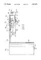
- FIG. 1is a plan view of an assembled fuel sender unit according to the present invention
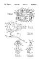
- FIG. 2is an exploded assembly view of the components of the fuel sender of FIG. 1;
- FIG. 3is a rear side view of the fuel sender of FIG. 1;
- FIG. 4is a plan view of a support arm of the fuel sender housing of FIG. 1;
- FIG. 4Ais a side view of the support arm of FIG. 4;
- FIG. 5is a plan view of a wiper arm of the assembled fuel sender of FIG. 1;
- FIG. 5Ais a side view of the wiper arm of FIG. 5;
- FIG. 6is a plan view of the housing of the fuel sender of FIG. 1;
- FIG. 7is a bottom view of the housing of the FIG. 6.
- a fuel sender unit 10comprising a plastic rheostat housing 12 supporting a thick film resistor card 16.
- Resistor card 16defines an arcuate array of spaced resistive conductor pads 18, and is securely mounted on plastic housing 12 by a plurality of snap-fit locking tabs 20 integrally molded in the housing.
- Housing 12is itself securely mounted on a suitable mounting fixture 11 in the interior of a fuel tank, via bifurcated snap lock feet 14 inserted into mounting slots 13.
- An electrically-conductive positive terminal 22is mounted on the housing, connected by blade connector 22A to an external electrical lead (not shown), and to resistor card 16 by soldered appurtenance arm 23.
- a flat, plate-like, electrically-conductive ground terminal 24is also supported on housing 12, supported on surfaces 30 of mounting posts 34 above and parallel to the plane of resistor card 16 in a manner described below.
- Ground terminal 24includes a central hole or pivot bearing 25 through which the horizontal pivot pin portion 102 of a wire float arm assembly 100 extends in rotatable fashion.
- Ground terminal 24includes a circular central body portion 24a and two opposed rectangular legs 114 with which terminal 24 is mounted to posts 34.
- the float arm assemblyincludes wire float arm 101, a pivot pin 102, a float pin 104 parallel to pin 102 on the free end of wire float arm 101, and a cylindrical float 106 securely mounted on float pin 104 via a suitable through-bore and groove 108.
- float 106is made from a fuel-resistant closed cell foam, for example NitrophylTM.
- plastic carrier or support arm assembly 50is connected to float arm 101 and is pivotally mounted on housing 12 coaxial with the pivot pin 102 of float arm assembly 100.
- plastic support arm 50includes a circular hub 52 from whose lower surface extends a cylindrical pivot bushing 54.
- the lower surface 56 of pivot bushing 54defines an annular axial thrust bearing surface.
- Support arm 50also includes an upper annular flange 58, chamfered at 59.
- a tightly toleranced bore 60 of a diameter approximately equal to that of float arm pivot pin 102extends through annular flange 58, circular hub 52 and pivot bushing 54.
- the top surface of circular hub 52has an L-shaped retainer hook 62 formed on its rear edge and a heat stake pin 64 on its front portion, hook 62 and heat stake 64 pin aligned with the line of symmetry of support arm 50.
- Support arm 50further includes a pair of spaced support beams 66 having angled extensions connected to a triangular or arrowhead-shaped support head 70.
- Support head 70includes two pairs of chamfered locking tabs 72 which secure wire float arm 101 in a snap-fit. Head 70 is also provided with angled stop surfaces 74 whose angle corresponds to that of the arcuate resistor array 18 on resistor card 16.
- the pivot bushing 54 of plastic support arm 50is mounted in rotatable fashion within a cylindrical blind bore 28 on plastic housing 12. Bore 28 orients support arm 50 during assembly, but has a diameter slightly greater than bushing 54 and does not engage support arm 50 after pivot pin 102 is inserted therethrough to align it with the float arm pivot axis. Bore 28 surrounds an annular thrust bearing surface 30 which mates with lower bearing surface 56 to permit smooth, level rotation of support arm 50 relative to housing 12. Stops 75 on housing 12 limit the arc of travel of support arm 50 by abutting stop surfaces 74.
- Bore 28 in housing 12also includes a chamfered bore 31 of a diameter approximately equal to that of float arm pivot pin 102.
- FIGS. 1 and 2show that ground terminal pivot bearing 25, support arm bore 60 and housing pivot bore 31 are aligned when housing 12, support arm 50, ground terminal 24 and float arm assembly 100 are assembled, with float arm pivot pin 102 extending through 25, 60, 31 and wire arm 101 fully engaged in tabs 72.
- housing 12includes a cylindrical radial bearing sleeve 26 extending from its lower surface. Pivot bore 31 extends through sleeve 26 to define a second pivot bearing for pivot pin 102.
- support arm 50 and float arm assembly 100are assembled to housing 12 as best shown in FIGS. 1 and 3, hole 25 and sleeve 26 define axially spaced bearing/support surfaces for pivot pin 102.
- Support arm 50is connected by tabs 72 to move with float arm assembly 100 therebetween, its lower bearing surface 56 mating with axial bearing surface 30 in housing 12 to define a smooth, planar axial bearing/support surface.
- Wiper arm 80is carried on support arm 50 between support arm hub 52 and the lower surface of ground terminal 24.
- Wiper arm 80includes a body portion 82 having a circular central cutout 84 dimensioned to fit over annular flange 58 on support arm 50.
- Wiper arm 80also includes a circular cutout 86 dimensioned to mate with heat stake pin 64, and a rectangular cutout 88 dimensioned to mate with L-shaped retainer hook 62.
- Circular cutout 86 and 84 and rectangular cutout 88are radially spaced on wiper arm 80 so that retainer hook 62 overlies wiper arm body 82 when wiper arm 80 is assembled to support arm 50.
- axial and radial gaps between the inner surfaces of L-shaped retainer hook 62 and wiper arm body 82create a sliding expansion joint to prevent wiper arm contact force variation due to differential metal/plastic expansion.
- Wiper arm 80includes two resilient inner contact arms 90 bent upwardly at an angle relative to body 82.
- An outer resilient contact arm 92,93extends from body 82 at a downward angle relative thereto to maintain a contact rivet 96 in contact with resistor card 16.
- Outer contact arm 92comprises twin beams separated by a triangular cutout region 94.
- wiper arm 80is carried by support arm 50 such that inner contact arms 90 remain in continuous sliding contact with the lower surface of portion 24a of ground terminal 24, and contact rivet 96 on the end of outer contact arm 92 remains in continuous sliding contact with arcuate resistor array 18 on card 16.
- the movementis transmitted via float arm 101 and support arm 50 to wiper 80 to move contact rivet 96 along the resistive path 18, the change in resistance measured to determine the level of fuel in the tank in known manner.
- Stop surfaces 74 on support arm 50engage stop posts 75 on plastic housing 12 to limit motion of the float arm assembly and contact rivet 96 to the arcuate resistor array 18.
- the dimensions, tolerances and connecting and bearing/support structures of the fuel sender 10are designed and manufactured in a manner to optimize the stability, accuracy and repeatability of the sender unit.
- the snap-lock feet 14 of plastic housing 12are bifurcated, sufficiently flexible and spaced far enough apart to remain loaded under tension when fuel sender 10 is mounted to a fixture such as that shown schematically at 11 in FIG. 2.
- the horizontal spacing between flexible lock feet 14ensures that they mate tightly with a wide range of mounting slots 13, each pair of bifurcated feet 14 exerting an outward and axial loading tension on the slot after insertion. This prevents housing 12 from rotating or shifting both axially and in the plane of card 16 relative to fixture 11, which would affect the accuracy of sender calibration by altering the position of float 106 and wiper contact 96 relative to resistor card 16 for a given fuel level.
- Locking tabs 20, 20'which secure resistor card 16 to housing 12 in two planes are curved and tapered from base to tip; i.e., tabs 20 are thicker at their base and taper to a thinner cross-section at their tip. This is a substantial improvement over traditional rectangular cantilever beams, the curved and tapered tabs 20, 20' of the present invention distributing loading stresses more evenly throughout the tabs to prevent material failures. This even distribution of stress serves to reduce the effect of plastic creep found at stress concentrations during temperature swings in the interior of the fuel tank and during gross deformations during the assembly process.
- resistor card 16is initially inserted underneath the four inboard tabs 20, the opposite edge subsequently snapped under the two outboard tabs 20'. In the illustrated embodiment only the two inside inboard tabs 20 actually engage the resistor card surface; the other two provide a backup function. However, it will be apparent to those skilled in the art that all four or other suitable numbers could be used.
- tabs 20, 20' and small "speed bumps" or rounded beads 21a below the inboard tabssecure card 16 in the left-right direction in FIG. 1.
- Card 106is calibrated by sliding it up or down and soldering or otherwise affixing it to arm 23 of the positive terminal 22.
- the flattened, offset ends 20a on outboard tabs 20', the tapered tips 20b on inboard tabs 20, and planar mounting ribs 19 on housing 12positively hold card 16 from moving in a plane perpendicular to housing 12.
- Flattened ends 20aengage the surface of card 16 and with the edge-engaging surface of outboard tabs 20' keep card 16 tensioned in two planes when card 16 is mounted on non-deflecting ribs 19, while the tapered tips 20b of the inboard tabs deform or crush against the surface of card 16.
- through-holes 21extending through plastic housing 12 in association with tabs 20', best shown in FIGS. 6 and 7.
- Through-holes 21improve the deflection of the cantilever locking tabs 20, 20' which is particularly helpful in automation-assisted assembly of card 16 to housing 12 and during calibration, by permitting access to the undersurface of tabs 20, 20' for deflection/retraction by automated assembly equipment such as pins inserted through holes 21.
- two edge datums in the form of semi-circular "speed bumps” 21aare provided, to which the left edge of resistor card 16 is matched during assembly.
- the rounded tops of speed bumps 21aprecisely locate the card 16 during assembly, and further provide a sliding surface for the card edge in the up-down direction during calibration.
- the "window" created by through-holes 21 through and housing 12will show uneven gaps between card 16 and housing 12 if not properly positioned.
- Circular through-holes 27are also formed in housing 12, providing access for manual or automated assembly tools or sensors to sense and locate the position of card 16.
- One hole 27is associated with the "bottom” edge of the resistor card opposite terminal 22 to align it in the up/down direction, and a second hole 27 is located at the "right" edge of card 16 opposite terminal 24 to check location in the left/right direction.
- Another critical area for fuel sender accuracyis the rotational mounting and support of the float arm assembly 100 which drives conductive wiper arm 80 relative to card 16 and ground terminal 24. Unevenness or improper alignment of the float arm pivot axis and bearing/support surfaces can cause premature wear of moving parts, fluctuating wiper arm contact forces and rotational instability, all of which reduce the accuracy and effective lifespan of fuel sender 10.
- ground terminal 24The uniformity, stability and alignment of radial bearing surface 25 in ground terminal 24 is enhanced by the method and structure for mounting ground terminal 24 to plastic housing 12.
- Widely-spaced, solid rectangular support posts 34, wide, rectangular ground terminal support legs 114, and long crimping legs 116provide great stability to terminal 24 and therefore to bearing hole 25.
- legs 114 on support surfaces 36 of support posts 34further ensures good initial and maintained alignment of bearing hole 25 relative to card 16 and the axial alignment and bearing structures/surfaces of housing 12 and support arm 50.
- Chamfered pins 38 on support posts 34orient and wedge mounting holes 118,120 of ground terminal 24 tightly in place.
- Mounting pins 38 on support surfaces 36are integrally molded with housing 12 and mate with mounting pin slots 118,120 on legs 114 to precisely position the ground terminal above and parallel to the plane of the resistor card.
- the taper of mounting pins 38provides a tight wedge fit when legs 114 of the ground terminal are flush with support surfaces 36, further reducing the risk of shifting or unevenly loading bearing 25 caused by thermal expansion differences between housing 12 and terminal 24.
- the elongated mounting pin cutout 120provides tolerance in the up-down direction, maintaining bearing hole alignment in one plane without exerting loading forces on the rheostat housing 12.
- Locking tabs or legs 116 on the ends of legs 114mate with chamfered slots 39 on the outside edges of support post 34, supplying some orientation to ground terminal 24 to keep it flat on support surfaces 36.
- Locking tabs 116are further provided with splayed or bifurcated prongs 117 which spread apart and remain loaded in tension once inserted in slots 39, stabilizing ground terminal 24 relative to housing 12 similar to the manner in which bifurcated snap lock feet 14 stabilize plastic housing 12 relative to fixture 11.
- ground terminal support surfaces 36 and parallel support arm bearing surface 30controls the contact force of inner wiper arms 90 against the lower surface of ground terminal 24.
- the present inventionrequires control over only two dimensions in the plastic housing 12, and one on the plastic support arm 50, during manufacture to ensure proper contact force for all points of the wiper arm assembly.
- alignment cutouts 118,120 and bearing hole 25are punched simultaneously to eliminate positioning errors. In particular, this helps align the ground terminal bearing 25 with the housing bearing 31 to achieve an accurate wiper arm axis of rotation.
- resistor card 16is properly aligned on housing 12 soldering or otherwise affixing connector 23 of positive terminal 22 secures the card relative to housing 12.
- the manner of mounting positive terminal 22 in slot 15 in housing 12 and its connection to card 16prevents shifting of resistor card 16 if the connector end 22a of terminal 22 is deflected, for example when making an electrical connection.
- Slot 15 in housing 12is provided with a number of staggered and opposed chamfered teeth 15a which "bite" into mounting tab 22b of terminal 22 to securely lock it relative to housing 12.
- small slots 22d on terminal mounting tab 22blockingly engage the two outboard teeth 15a.
- the outboard wall 15b in the illustrated embodiment of slot 15curves or bows inwardly, and yields when terminal 22 is inserted to maintain spring tension on terminal 22.
- Connector arm 23 connecting positive terminal 22 to card 16extends from mounting tab 22b, not connector portion 22a, and is therefore isolated from loading forces exerted on connector portion 22a of terminal 22.
- Mounting tab 22bis further provided with tapered ribs 22c along its edges to further tighten its fit in slot 15.
- connector arm 23further includes a small tab 23a engaging the inner surface of housing 12 to further prevent any shifting of arm 23 and card 16 relative to the housing.
- L-shaped retainer hook 62eliminates contact force changes on wiper arm 80 to differential expansion of the plastic support assembly 50 and the metal wiper.
- the gap or tolerance between rectangular cutout 88 and retainer hook 62allows relative expansion/contraction between support arm 50 and wiper arm 80 without loading on either part.
- the structure and method of manufacture of the wiper arm itselfadds to the stability, uniformity and accuracy of the fuel sender unit 10.
- the width of twin beams 93 of outer contact arm 92controls the spring rate of contact arm 92 and therefore the contact force of rivet 96 on card 16.
- the width of twin beams 93is a function of the size or width of triangular cutout 94.
- the heat stake cutout 86 in wiper arm assembly 80includes a rectangular slot 87 extending to central opening 84.
- This anti-rotation featureeliminates hysteresis in the sender readings caused by lost motion of the contact rivet relative to rotation of the float arm and support arm 50.
- the wiper arm contact forces, and the moments created thereby,are balanced in magnitude and direction to eliminate preferential tip of the wiper arm in one direction or another to prevent the contact forces from tipping the bearing axis off center, which would cause hysteresis and contribute to bearing wear. This is achieved by balancing the outer wiper arm moment relative to the moments exerted by the two symmetrical inner contact arms 90.
- Ground terminal 24is made of a material softer than that of wiper arm 80 to provide a sacrificial wear surface with respect to the inner contact arms 90. This sacrificial wear provides a continuously fresh contact surface with good electrical characteristics throughout the sender life.
- the lower side of the ground terminal 24 in contact with inner wiper arms 90is further provided with a radial pattern of spaced slots (not shown), angularly positioned to prevent simultaneous contact of inner arms 90 with slots. The edges of the slots wipe sacrificial wear debris from the wiper arms to improve the electrical signal.
Landscapes
- Physics & Mathematics (AREA)
- Fluid Mechanics (AREA)
- General Physics & Mathematics (AREA)
- Level Indicators Using A Float (AREA)
Abstract
Description
Claims (14)
Priority Applications (1)
| Application Number | Priority Date | Filing Date | Title |
|---|---|---|---|
| US08/061,868US5341679A (en) | 1993-05-14 | 1993-05-14 | Resistor card fuel level sender with float arm actuator |
Applications Claiming Priority (1)
| Application Number | Priority Date | Filing Date | Title |
|---|---|---|---|
| US08/061,868US5341679A (en) | 1993-05-14 | 1993-05-14 | Resistor card fuel level sender with float arm actuator |
Publications (1)
| Publication Number | Publication Date |
|---|---|
| US5341679Atrue US5341679A (en) | 1994-08-30 |
Family
ID=22038666
Family Applications (1)
| Application Number | Title | Priority Date | Filing Date |
|---|---|---|---|
| US08/061,868Expired - LifetimeUS5341679A (en) | 1993-05-14 | 1993-05-14 | Resistor card fuel level sender with float arm actuator |
Country Status (1)
| Country | Link |
|---|---|
| US (1) | US5341679A (en) |
Cited By (43)
| Publication number | Priority date | Publication date | Assignee | Title |
|---|---|---|---|---|
| FR2751745A1 (en)* | 1996-07-26 | 1998-01-30 | Marwal Systems | FUEL GAUGE DEVICE FOR A MOTOR VEHICLE TANK |
| US5746088A (en)* | 1996-02-09 | 1998-05-05 | General Motors Corporation | Fuel system low current rheostat |
| US5765435A (en)* | 1994-10-27 | 1998-06-16 | Pierburg Ag | Apparatus for indicating fuel level in a fuel tank |
| DE19732981A1 (en)* | 1997-07-31 | 1999-02-18 | Mannesmann Vdo Ag | Level sensor |
| USD419091S (en)* | 1999-04-01 | 2000-01-18 | Rochester Gauges, Inc. | Liquid level sender assembly |
| US6025772A (en)* | 1998-07-08 | 2000-02-15 | Chen; Jack | Potentiometer |
| US6089086A (en) | 1997-08-26 | 2000-07-18 | Rochester Gauges, Inc. | Liquid level gauge |
| US6142018A (en)* | 1997-11-10 | 2000-11-07 | Cts Corporation | Conductor burnishing |
| WO2000039536A3 (en)* | 1998-12-31 | 2001-01-11 | Methode Electronics Inc | Fuel level sensor with miniaturized ceramic resistor card |
| US6176134B1 (en)* | 1997-12-09 | 2001-01-23 | Mannesmann Vdo Ag | Filling level sensor |
| US6267007B1 (en)* | 1997-10-20 | 2001-07-31 | Mannesmann Vdo Ag | Level sensor |
| US20030037612A1 (en)* | 2001-08-27 | 2003-02-27 | Yazaki Corporation | Apparatus for detecting liquid level |
| US6658934B1 (en)* | 1999-04-01 | 2003-12-09 | Rochester Gauges, Inc. | Liquid level sender assembly |
| US6711950B1 (en)* | 1999-11-30 | 2004-03-30 | Nippon Seiki Co., Ltd. | Liquid level detector |
| US20040221645A1 (en)* | 2003-05-08 | 2004-11-11 | Brzozowski Marc A. | Sealed fuel level sensor |
| DE10336791A1 (en)* | 2003-08-08 | 2005-03-17 | Siemens Ag | Level sensor, measuring method for determining a contact pressure of a contact against a contact path of a potentiometer and apparatus for carrying out the measuring method |
| US20050066723A1 (en)* | 2003-09-26 | 2005-03-31 | Robert Bosch Corporation | Fuel level sending unit and contact button for same |
| US20050139003A1 (en)* | 2003-02-26 | 2005-06-30 | Rudolph Bergsma Trust | Hermetic fuel level sender |
| US20060000279A1 (en)* | 2004-07-01 | 2006-01-05 | Jamnia Mohammad A | Device employing magnetic flux to measure the level of fluid in a tank |
| US20060019536A1 (en)* | 2004-07-22 | 2006-01-26 | Yazaki Corporation | Liquid level detection apparatus |
| US20060042379A1 (en)* | 2004-08-30 | 2006-03-02 | Ireland Hugh W | Sealed fuel level sensor |
| US20060219003A1 (en)* | 2005-04-05 | 2006-10-05 | Forgue John R | Electrostatic charge control for in-tank fuel module components |
| US20070006648A1 (en)* | 2003-05-30 | 2007-01-11 | Nippon Seiki Co. Ltd. | Liquid level detector |
| US20070074568A1 (en)* | 2005-09-30 | 2007-04-05 | Hans-Guenter Benner | Level transmitter |
| US20070079872A1 (en)* | 2005-10-07 | 2007-04-12 | Alfmeier Corporation | Vent valve assembly with lever arrangement |
| US20070151337A1 (en)* | 2006-01-04 | 2007-07-05 | Cochran Gary D | Magnetically coupled drive for a sealed liquid level sender |
| US20070214882A1 (en)* | 2004-08-30 | 2007-09-20 | Ulf Sawert | Sealed fuel level sensors |
| US20070283755A1 (en)* | 2006-06-07 | 2007-12-13 | Gm Global Technology Operations, Inc. | Fuel Tank Float Arm Assembly |
| US7318576B2 (en) | 2004-05-27 | 2008-01-15 | Alfmeier Prazision Ag Baugruppen Und Systemlosungen | Bi-directional air valve for a tank system of a motor vehicle |
| WO2008125478A1 (en)* | 2007-04-11 | 2008-10-23 | Continental Automotive Gmbh | Level indicator |
| WO2008142709A1 (en)* | 2007-05-23 | 2008-11-27 | Pricol Limited | A fluid level sensor and a method thereof |
| US20080295592A1 (en)* | 2007-05-31 | 2008-12-04 | Yazaki Corporation | Liquid level detection device |
| USD583693S1 (en) | 2006-03-30 | 2008-12-30 | Rochester Gauges, Inc. | Dial assembly for a gauge |
| US20090107393A1 (en)* | 2007-10-31 | 2009-04-30 | Rochester Gauges, Inc. | Gauge head assembly with non-magnetic insert |
| US20090266157A1 (en)* | 2008-04-24 | 2009-10-29 | Hisafumi Maruo | Liquid-level detecting apparatus |
| US7654281B2 (en) | 2004-01-22 | 2010-02-02 | Rochester Gauges, Inc. | Gauge assembly having a stop fill device |
| US7726334B2 (en) | 2004-01-22 | 2010-06-01 | Rochester Gauges, Inc. | Service valve assembly having a stop-fill device and remote liquid level indicator |
| US7921873B2 (en) | 2004-01-22 | 2011-04-12 | Rochester Gauges, Inc. | Service valve assembly having a stop-fill device and a liquid level indicating dial |
| US20140373623A1 (en)* | 2011-12-16 | 2014-12-25 | Continential Automotive Gmbh | Filling level sensor in a fuel tank of a motor vehicle, production method for such a filling level sensor, and method for operating such a filling level sensor |
| USD871456S1 (en) | 2018-09-06 | 2019-12-31 | Trico Group, LLC | Fuel pump assembly |
| US10634102B2 (en) | 2018-09-06 | 2020-04-28 | Trico Group, LLC | Fuel pump assembly |
| US10648848B2 (en)* | 2017-06-05 | 2020-05-12 | Yazaki Corporation | Mounting structure of liquid level detecting device |
| US11460335B2 (en)* | 2016-07-22 | 2022-10-04 | Vitesco Technologies GmbH | Filling level indicator |
Citations (31)
| Publication number | Priority date | Publication date | Assignee | Title |
|---|---|---|---|---|
| FR1389934A (en)* | 1964-04-07 | 1965-02-19 | Borletti Spa | Fuel level indicator, especially for cars |
| US3774449A (en)* | 1972-10-16 | 1973-11-27 | Gen Motors Corp | Fuel level sensor for a rotating fuel tank |
| US3798970A (en)* | 1973-02-16 | 1974-03-26 | Gen Motors Corp | Fuel level sender for a vehicle fuel tank |
| US4107998A (en)* | 1975-04-30 | 1978-08-22 | Stewart-Warner Corporation | Petrol tank gauges |
| US4114130A (en)* | 1977-11-25 | 1978-09-12 | General Motors Corporation | Fuel level sender with molded plastic case |
| US4157038A (en)* | 1977-04-28 | 1979-06-05 | Niles Parts Co., Ltd. | Liquid meter with an enlarged range of indication mechanism |
| GB2048495A (en)* | 1979-04-26 | 1980-12-10 | Plessey Co Ltd | Liquid level sensor |
| US4441364A (en)* | 1981-05-22 | 1984-04-10 | Thomas G. Faria Corp. | Liquid-level transducer/indicator |
| JPS6018720A (en)* | 1983-07-13 | 1985-01-30 | Koito Mfg Co Ltd | Contact-point holding mechanism in liquid level gage using thick film resistor |
| US4532491A (en)* | 1981-11-21 | 1985-07-30 | Vdo Adolf Schindling Ag | Liquid-level transmitter with bell jar housing for gasoline tanks |
| US4557144A (en)* | 1982-09-27 | 1985-12-10 | Fiat Auto S.P.A. | Electric level sensor for motor vehicle fuel tanks |
| US4685332A (en)* | 1986-07-07 | 1987-08-11 | Chrysler Motors Corporation | Liquid level sensing device |
| JPS62201324A (en)* | 1986-02-28 | 1987-09-05 | Nippon Seiki Co Ltd | Liquid level detector |
| US4700170A (en)* | 1985-04-12 | 1987-10-13 | Stewart-Warner Corporation | Condition sensing rheostat and method of manufacture |
| US4780705A (en)* | 1987-02-10 | 1988-10-25 | Enterprise Brass Works Of Florida, Inc. | Overfill sensing system |
| US4841771A (en)* | 1988-07-08 | 1989-06-27 | Chrysler Motors Corporation | Fuel level sensor |
| US4843883A (en)* | 1988-11-21 | 1989-07-04 | Chrysler Motors Corporation | Differential pressure fluid level sensor |
| US4845486A (en)* | 1986-09-12 | 1989-07-04 | Robert Scully | Residential fuel-oil level reporting and alarm system |
| US4870861A (en)* | 1986-10-24 | 1989-10-03 | Yazaki Corporation | Liquid level indicator |
| US4873865A (en)* | 1988-12-27 | 1989-10-17 | Ford Motor Company | Fuel sender assembly requiring no calibration |
| US4911011A (en)* | 1988-11-01 | 1990-03-27 | Rochester Gauges, Inc. | Gauge with magnetically driven voltage divider |
| US4924704A (en)* | 1988-12-27 | 1990-05-15 | Ford Motor Company | Fuel sender assembly requiring no calibration and having reduced wear |
| US4928526A (en)* | 1988-11-29 | 1990-05-29 | Stewart Warner Instrument Corporation | Universal fuel sender |
| US4931764A (en)* | 1988-12-27 | 1990-06-05 | Ford Motor Company | Low wear resistor card for use in a liquid fuel sender circuit |
| US4967181A (en)* | 1988-09-12 | 1990-10-30 | Yazaki Corporation | Fuel level gauge provided with an apparatus for issuing a warning on the amount of remaining fuel |
| US4974570A (en)* | 1989-05-05 | 1990-12-04 | Carter Automotive Company, Inc. | Fuel supply module |
| US4986113A (en)* | 1989-09-18 | 1991-01-22 | Computerized Tank Testing, Inc. | Liquid tank leakage detection system |
| US5184510A (en)* | 1991-12-23 | 1993-02-09 | Ford Motor Company | Liquid level sensor |
| US5191912A (en)* | 1992-01-10 | 1993-03-09 | Mcdaniel Roy L | Liquid level controller |
| US5197445A (en)* | 1990-09-04 | 1993-03-30 | Robert Bosch Gmbh | Fuel-supply system for an internal combustion engine |
| US5201298A (en)* | 1991-12-27 | 1993-04-13 | Paccar Inc. | Combination sending unit and fuel draw automatic shutoff valve |
- 1993
- 1993-05-14USUS08/061,868patent/US5341679A/ennot_activeExpired - Lifetime
Patent Citations (31)
| Publication number | Priority date | Publication date | Assignee | Title |
|---|---|---|---|---|
| FR1389934A (en)* | 1964-04-07 | 1965-02-19 | Borletti Spa | Fuel level indicator, especially for cars |
| US3774449A (en)* | 1972-10-16 | 1973-11-27 | Gen Motors Corp | Fuel level sensor for a rotating fuel tank |
| US3798970A (en)* | 1973-02-16 | 1974-03-26 | Gen Motors Corp | Fuel level sender for a vehicle fuel tank |
| US4107998A (en)* | 1975-04-30 | 1978-08-22 | Stewart-Warner Corporation | Petrol tank gauges |
| US4157038A (en)* | 1977-04-28 | 1979-06-05 | Niles Parts Co., Ltd. | Liquid meter with an enlarged range of indication mechanism |
| US4114130A (en)* | 1977-11-25 | 1978-09-12 | General Motors Corporation | Fuel level sender with molded plastic case |
| GB2048495A (en)* | 1979-04-26 | 1980-12-10 | Plessey Co Ltd | Liquid level sensor |
| US4441364A (en)* | 1981-05-22 | 1984-04-10 | Thomas G. Faria Corp. | Liquid-level transducer/indicator |
| US4532491A (en)* | 1981-11-21 | 1985-07-30 | Vdo Adolf Schindling Ag | Liquid-level transmitter with bell jar housing for gasoline tanks |
| US4557144A (en)* | 1982-09-27 | 1985-12-10 | Fiat Auto S.P.A. | Electric level sensor for motor vehicle fuel tanks |
| JPS6018720A (en)* | 1983-07-13 | 1985-01-30 | Koito Mfg Co Ltd | Contact-point holding mechanism in liquid level gage using thick film resistor |
| US4700170A (en)* | 1985-04-12 | 1987-10-13 | Stewart-Warner Corporation | Condition sensing rheostat and method of manufacture |
| JPS62201324A (en)* | 1986-02-28 | 1987-09-05 | Nippon Seiki Co Ltd | Liquid level detector |
| US4685332A (en)* | 1986-07-07 | 1987-08-11 | Chrysler Motors Corporation | Liquid level sensing device |
| US4845486A (en)* | 1986-09-12 | 1989-07-04 | Robert Scully | Residential fuel-oil level reporting and alarm system |
| US4870861A (en)* | 1986-10-24 | 1989-10-03 | Yazaki Corporation | Liquid level indicator |
| US4780705A (en)* | 1987-02-10 | 1988-10-25 | Enterprise Brass Works Of Florida, Inc. | Overfill sensing system |
| US4841771A (en)* | 1988-07-08 | 1989-06-27 | Chrysler Motors Corporation | Fuel level sensor |
| US4967181A (en)* | 1988-09-12 | 1990-10-30 | Yazaki Corporation | Fuel level gauge provided with an apparatus for issuing a warning on the amount of remaining fuel |
| US4911011A (en)* | 1988-11-01 | 1990-03-27 | Rochester Gauges, Inc. | Gauge with magnetically driven voltage divider |
| US4843883A (en)* | 1988-11-21 | 1989-07-04 | Chrysler Motors Corporation | Differential pressure fluid level sensor |
| US4928526A (en)* | 1988-11-29 | 1990-05-29 | Stewart Warner Instrument Corporation | Universal fuel sender |
| US4931764A (en)* | 1988-12-27 | 1990-06-05 | Ford Motor Company | Low wear resistor card for use in a liquid fuel sender circuit |
| US4924704A (en)* | 1988-12-27 | 1990-05-15 | Ford Motor Company | Fuel sender assembly requiring no calibration and having reduced wear |
| US4873865A (en)* | 1988-12-27 | 1989-10-17 | Ford Motor Company | Fuel sender assembly requiring no calibration |
| US4974570A (en)* | 1989-05-05 | 1990-12-04 | Carter Automotive Company, Inc. | Fuel supply module |
| US4986113A (en)* | 1989-09-18 | 1991-01-22 | Computerized Tank Testing, Inc. | Liquid tank leakage detection system |
| US5197445A (en)* | 1990-09-04 | 1993-03-30 | Robert Bosch Gmbh | Fuel-supply system for an internal combustion engine |
| US5184510A (en)* | 1991-12-23 | 1993-02-09 | Ford Motor Company | Liquid level sensor |
| US5201298A (en)* | 1991-12-27 | 1993-04-13 | Paccar Inc. | Combination sending unit and fuel draw automatic shutoff valve |
| US5191912A (en)* | 1992-01-10 | 1993-03-09 | Mcdaniel Roy L | Liquid level controller |
Cited By (70)
| Publication number | Priority date | Publication date | Assignee | Title |
|---|---|---|---|---|
| US5765435A (en)* | 1994-10-27 | 1998-06-16 | Pierburg Ag | Apparatus for indicating fuel level in a fuel tank |
| US5746088A (en)* | 1996-02-09 | 1998-05-05 | General Motors Corporation | Fuel system low current rheostat |
| FR2751745A1 (en)* | 1996-07-26 | 1998-01-30 | Marwal Systems | FUEL GAUGE DEVICE FOR A MOTOR VEHICLE TANK |
| WO1998004890A1 (en)* | 1996-07-26 | 1998-02-05 | Marwal Systems | Fuel gauging system for a motor vehicle fuel tank |
| US6305220B1 (en)* | 1996-07-26 | 2001-10-23 | Marwal Systems | Fuel gauging system for a motor vehicle fuel tank |
| DE19732981A1 (en)* | 1997-07-31 | 1999-02-18 | Mannesmann Vdo Ag | Level sensor |
| EP0895068A3 (en)* | 1997-07-31 | 2000-03-08 | Mannesmann VDO Aktiengesellschaft | Level sensor |
| US6089086A (en) | 1997-08-26 | 2000-07-18 | Rochester Gauges, Inc. | Liquid level gauge |
| US6267007B1 (en)* | 1997-10-20 | 2001-07-31 | Mannesmann Vdo Ag | Level sensor |
| US6142018A (en)* | 1997-11-10 | 2000-11-07 | Cts Corporation | Conductor burnishing |
| US6176134B1 (en)* | 1997-12-09 | 2001-01-23 | Mannesmann Vdo Ag | Filling level sensor |
| US6025772A (en)* | 1998-07-08 | 2000-02-15 | Chen; Jack | Potentiometer |
| WO2000039536A3 (en)* | 1998-12-31 | 2001-01-11 | Methode Electronics Inc | Fuel level sensor with miniaturized ceramic resistor card |
| US6209392B1 (en)* | 1998-12-31 | 2001-04-03 | Methode Electronics, Inc. | Fuel level sensor with miniaturized ceramic resistor card |
| USD419091S (en)* | 1999-04-01 | 2000-01-18 | Rochester Gauges, Inc. | Liquid level sender assembly |
| US6658934B1 (en)* | 1999-04-01 | 2003-12-09 | Rochester Gauges, Inc. | Liquid level sender assembly |
| US6711950B1 (en)* | 1999-11-30 | 2004-03-30 | Nippon Seiki Co., Ltd. | Liquid level detector |
| EP1174692A4 (en)* | 1999-11-30 | 2005-05-18 | Nippon Seiki Co Ltd | LIQUID LEVEL DETECTOR |
| US20030037612A1 (en)* | 2001-08-27 | 2003-02-27 | Yazaki Corporation | Apparatus for detecting liquid level |
| US7343799B2 (en)* | 2001-08-27 | 2008-03-18 | Yazaki Corporation | Apparatus for detecting liquid level |
| US20050139003A1 (en)* | 2003-02-26 | 2005-06-30 | Rudolph Bergsma Trust | Hermetic fuel level sender |
| US6868724B2 (en)* | 2003-05-08 | 2005-03-22 | Ti Group Automotive Systems, L.L.C. | Sealed fuel level sensor |
| US20040221645A1 (en)* | 2003-05-08 | 2004-11-11 | Brzozowski Marc A. | Sealed fuel level sensor |
| US7437929B2 (en)* | 2003-05-30 | 2008-10-21 | Nippon Seiki Co., Ltd. | Liquid level detector |
| US20070006648A1 (en)* | 2003-05-30 | 2007-01-11 | Nippon Seiki Co. Ltd. | Liquid level detector |
| US20060179937A1 (en)* | 2003-08-08 | 2006-08-17 | Hans-Guenter Benner | Fill level sensor, measuring method for determining a contact pressure of a contact against a contact path of a potentiometer and device for carrying out the measuring method |
| DE10336791B4 (en)* | 2003-08-08 | 2005-07-28 | Siemens Ag | Level sensor, measuring method for determining a contact pressure of a contact against a contact path of a potentiometer and apparatus for carrying out the measuring method |
| DE10336791A1 (en)* | 2003-08-08 | 2005-03-17 | Siemens Ag | Level sensor, measuring method for determining a contact pressure of a contact against a contact path of a potentiometer and apparatus for carrying out the measuring method |
| US7043982B2 (en)* | 2003-09-26 | 2006-05-16 | Robert Bosch Corporation | Fuel level sending unit and contact button for same |
| US20050066723A1 (en)* | 2003-09-26 | 2005-03-31 | Robert Bosch Corporation | Fuel level sending unit and contact button for same |
| US7726334B2 (en) | 2004-01-22 | 2010-06-01 | Rochester Gauges, Inc. | Service valve assembly having a stop-fill device and remote liquid level indicator |
| US7654281B2 (en) | 2004-01-22 | 2010-02-02 | Rochester Gauges, Inc. | Gauge assembly having a stop fill device |
| US7921873B2 (en) | 2004-01-22 | 2011-04-12 | Rochester Gauges, Inc. | Service valve assembly having a stop-fill device and a liquid level indicating dial |
| US7318576B2 (en) | 2004-05-27 | 2008-01-15 | Alfmeier Prazision Ag Baugruppen Und Systemlosungen | Bi-directional air valve for a tank system of a motor vehicle |
| US7165450B2 (en)* | 2004-07-01 | 2007-01-23 | Mohammad Ali Jamnia | Variable position sensor employing magnetic flux and housing therefore |
| US20060000279A1 (en)* | 2004-07-01 | 2006-01-05 | Jamnia Mohammad A | Device employing magnetic flux to measure the level of fluid in a tank |
| US20060019536A1 (en)* | 2004-07-22 | 2006-01-26 | Yazaki Corporation | Liquid level detection apparatus |
| US7350413B2 (en)* | 2004-07-22 | 2008-04-01 | Yazaki Corporation | Liquid level detection apparatus |
| US20060042379A1 (en)* | 2004-08-30 | 2006-03-02 | Ireland Hugh W | Sealed fuel level sensor |
| US20070214882A1 (en)* | 2004-08-30 | 2007-09-20 | Ulf Sawert | Sealed fuel level sensors |
| US7555946B2 (en)* | 2004-08-30 | 2009-07-07 | Delphi Technologies, Inc. | Sealed fuel level sensors |
| US7140247B2 (en)* | 2005-04-05 | 2006-11-28 | Ti Group Automotive Systems, Llc | Electrostatic charge control for in-tank fuel module components |
| US20060219003A1 (en)* | 2005-04-05 | 2006-10-05 | Forgue John R | Electrostatic charge control for in-tank fuel module components |
| US20070074568A1 (en)* | 2005-09-30 | 2007-04-05 | Hans-Guenter Benner | Level transmitter |
| US20070079872A1 (en)* | 2005-10-07 | 2007-04-12 | Alfmeier Corporation | Vent valve assembly with lever arrangement |
| US7543597B2 (en) | 2005-10-07 | 2009-06-09 | Alfmeier Corporation | Vent valve assembly with lever arrangement |
| US7584658B2 (en)* | 2005-10-14 | 2009-09-08 | Siemens Aktiengesellschaft | Level transmitter |
| US20070151337A1 (en)* | 2006-01-04 | 2007-07-05 | Cochran Gary D | Magnetically coupled drive for a sealed liquid level sender |
| US7673509B2 (en) | 2006-01-04 | 2010-03-09 | Rudolph Bergsma Trust | Magnetically coupled drive for a sealed liquid level sender |
| USD583693S1 (en) | 2006-03-30 | 2008-12-30 | Rochester Gauges, Inc. | Dial assembly for a gauge |
| US20070283755A1 (en)* | 2006-06-07 | 2007-12-13 | Gm Global Technology Operations, Inc. | Fuel Tank Float Arm Assembly |
| US7467550B2 (en)* | 2006-06-07 | 2008-12-23 | Gm Global Technology Operations, Inc. | Fuel tank float arm assembly |
| WO2008125478A1 (en)* | 2007-04-11 | 2008-10-23 | Continental Automotive Gmbh | Level indicator |
| US8939022B2 (en)* | 2007-04-11 | 2015-01-27 | Continental Automotive Gmbh | Level indicator |
| US20100139394A1 (en)* | 2007-04-11 | 2010-06-10 | Continental Automotive Gmbh | Level Indicator |
| WO2008142709A1 (en)* | 2007-05-23 | 2008-11-27 | Pricol Limited | A fluid level sensor and a method thereof |
| US20100199759A1 (en)* | 2007-05-23 | 2010-08-12 | Dharmaraj Prasad | Fluid Level Sensor and a Method Thereof |
| US20080295592A1 (en)* | 2007-05-31 | 2008-12-04 | Yazaki Corporation | Liquid level detection device |
| US8024969B2 (en)* | 2007-05-31 | 2011-09-27 | Yazaki Corporation | Liquid level detection device |
| US7690323B2 (en) | 2007-10-31 | 2010-04-06 | Rochester Gauges, Inc. | Gauge head assembly with non-magnetic insert |
| US20090107393A1 (en)* | 2007-10-31 | 2009-04-30 | Rochester Gauges, Inc. | Gauge head assembly with non-magnetic insert |
| US8171787B2 (en)* | 2008-04-24 | 2012-05-08 | Yazaki Corporation | Liquid-level detecting apparatus |
| US20090266157A1 (en)* | 2008-04-24 | 2009-10-29 | Hisafumi Maruo | Liquid-level detecting apparatus |
| US20140373623A1 (en)* | 2011-12-16 | 2014-12-25 | Continential Automotive Gmbh | Filling level sensor in a fuel tank of a motor vehicle, production method for such a filling level sensor, and method for operating such a filling level sensor |
| US11460335B2 (en)* | 2016-07-22 | 2022-10-04 | Vitesco Technologies GmbH | Filling level indicator |
| US10648848B2 (en)* | 2017-06-05 | 2020-05-12 | Yazaki Corporation | Mounting structure of liquid level detecting device |
| USD871456S1 (en) | 2018-09-06 | 2019-12-31 | Trico Group, LLC | Fuel pump assembly |
| US10634102B2 (en) | 2018-09-06 | 2020-04-28 | Trico Group, LLC | Fuel pump assembly |
| US10865750B2 (en) | 2018-09-06 | 2020-12-15 | Trico Group, LLC | Fuel pump assembly |
| US11022080B2 (en) | 2018-09-06 | 2021-06-01 | Trico Group, LLC | Fuel pump assembly |
Similar Documents
| Publication | Publication Date | Title |
|---|---|---|
| US5341679A (en) | Resistor card fuel level sender with float arm actuator | |
| US20100199759A1 (en) | Fluid Level Sensor and a Method Thereof | |
| AU626335B2 (en) | Universal fuel sender | |
| US5466371A (en) | Cytocentrifugation device | |
| US6658934B1 (en) | Liquid level sender assembly | |
| US4343064A (en) | Device for connecting a wiper blade holder to a wiper arm | |
| US5211128A (en) | Automotive meter device having self-acting light-emitting pointer | |
| US6040705A (en) | Rolling electrical contactor | |
| US20100271061A1 (en) | Contact probe and socket | |
| US20080180117A1 (en) | Adjustable Force Electrical Contactor | |
| JPH04198830A (en) | Inclination measuring equipment of head lamp for automobile | |
| CN116519998A (en) | A probe adjustment part, a probe frame and a test platform | |
| US6219931B1 (en) | Target base for a measuring system | |
| TWI778403B (en) | Test probe, method of manufacturing the same, and test socket supporting the same | |
| US6386020B1 (en) | Rotary sensor capable of high-precision detection of rotation angle transmitted from outside | |
| AU656880B2 (en) | Heater bar assembly | |
| US6247239B1 (en) | Clinometric sensor | |
| EP0462944B1 (en) | Universal multicontact connection between an EWS probe card and a test card of a "test-on-wafer" station | |
| US4482122A (en) | Auto antenna mounting | |
| US3497858A (en) | Potentiometer | |
| US4556307A (en) | Adjusting apparatus for a doctor blade structure for copy machines | |
| CN216560676U (en) | Interface device, circuit board unit, and semiconductor test apparatus | |
| US4928083A (en) | Wiper for variable electrical resistor | |
| KR100276100B1 (en) | Binding structure of the reinforcement type flexible wire probe and the PCB block in which the probe is engaged | |
| JP3060164B2 (en) | Inspection probe device for IC test socket |
Legal Events
| Date | Code | Title | Description |
|---|---|---|---|
| STPP | Information on status: patent application and granting procedure in general | Free format text:APPLICATION UNDERGOING PREEXAM PROCESSING | |
| AS | Assignment | Owner name:G.T. PRODUCTS, INC., MICHIGAN Free format text:ASSIGNMENT OF ASSIGNORS INTEREST;ASSIGNORS:WALKOWSKI, PAUL D.;SCHLIEBE, DUANE M.;REEL/FRAME:006616/0992 Effective date:19930616 | |
| FEPP | Fee payment procedure | Free format text:PAYOR NUMBER ASSIGNED (ORIGINAL EVENT CODE: ASPN); ENTITY STATUS OF PATENT OWNER: LARGE ENTITY | |
| FPAY | Fee payment | Year of fee payment:4 | |
| FEPP | Fee payment procedure | Free format text:PAT HOLDER NO LONGER CLAIMS SMALL ENTITY STATUS, ENTITY STATUS SET TO UNDISCOUNTED (ORIGINAL EVENT CODE: STOL); ENTITY STATUS OF PATENT OWNER: LARGE ENTITY | |
| REFU | Refund | Free format text:REFUND - PAYMENT OF MAINTENANCE FEE, 8TH YR, SMALL ENTITY (ORIGINAL EVENT CODE: R2552); ENTITY STATUS OF PATENT OWNER: LARGE ENTITY | |
| FPAY | Fee payment | Year of fee payment:8 | |
| SULP | Surcharge for late payment | Year of fee payment:7 | |
| FEPP | Fee payment procedure | Free format text:ENTITY STATUS SET TO UNDISCOUNTED (ORIGINAL EVENT CODE: BIG.); ENTITY STATUS OF PATENT OWNER: LARGE ENTITY | |
| FPAY | Fee payment | Year of fee payment:12 |