US5341242A - Helmet mounted display - Google Patents
Helmet mounted displayDownload PDFInfo
- Publication number
- US5341242A US5341242AUS07/878,391US87839192AUS5341242AUS 5341242 AUS5341242 AUS 5341242AUS 87839192 AUS87839192 AUS 87839192AUS 5341242 AUS5341242 AUS 5341242A
- Authority
- US
- United States
- Prior art keywords
- image
- partially reflecting
- observer
- semi
- sagittal
- Prior art date
- Legal status (The legal status is an assumption and is not a legal conclusion. Google has not performed a legal analysis and makes no representation as to the accuracy of the status listed.)
- Expired - Lifetime
Links
- 230000003287optical effectEffects0.000claimsabstractdescription24
- 238000002310reflectometryMethods0.000claimsabstractdescription20
- 230000000694effectsEffects0.000description7
- 230000004075alterationEffects0.000description5
- 239000011248coating agentSubstances0.000description5
- 238000000576coating methodMethods0.000description5
- 230000003247decreasing effectEffects0.000description5
- 239000000463materialSubstances0.000description3
- 238000007792additionMethods0.000description2
- 230000007423decreaseEffects0.000description2
- 238000010586diagramMethods0.000description2
- 238000004519manufacturing processMethods0.000description2
- 238000000034methodMethods0.000description2
- 201000009310astigmatismDiseases0.000description1
- 238000010276constructionMethods0.000description1
- 238000012217deletionMethods0.000description1
- 230000037430deletionEffects0.000description1
- 230000008020evaporationEffects0.000description1
- 238000001704evaporationMethods0.000description1
- 239000000835fiberSubstances0.000description1
- 239000010408filmSubstances0.000description1
- 238000003384imaging methodMethods0.000description1
- 239000004973liquid crystal related substanceSubstances0.000description1
- 239000010409thin filmSubstances0.000description1
- 238000001771vacuum depositionMethods0.000description1
Images


Classifications
- G—PHYSICS
- G02—OPTICS
- G02B—OPTICAL ELEMENTS, SYSTEMS OR APPARATUS
- G02B27/00—Optical systems or apparatus not provided for by any of the groups G02B1/00 - G02B26/00, G02B30/00
- G02B27/01—Head-up displays
- G02B27/017—Head mounted
- G02B27/0172—Head mounted characterised by optical features
- G—PHYSICS
- G02—OPTICS
- G02B—OPTICAL ELEMENTS, SYSTEMS OR APPARATUS
- G02B27/00—Optical systems or apparatus not provided for by any of the groups G02B1/00 - G02B26/00, G02B30/00
- G02B27/01—Head-up displays
- G02B27/0101—Head-up displays characterised by optical features
- G02B2027/011—Head-up displays characterised by optical features comprising device for correcting geometrical aberrations, distortion
- G—PHYSICS
- G02—OPTICS
- G02B—OPTICAL ELEMENTS, SYSTEMS OR APPARATUS
- G02B27/00—Optical systems or apparatus not provided for by any of the groups G02B1/00 - G02B26/00, G02B30/00
- G02B27/01—Head-up displays
- G02B27/0101—Head-up displays characterised by optical features
- G02B2027/0123—Head-up displays characterised by optical features comprising devices increasing the field of view
- G—PHYSICS
- G02—OPTICS
- G02B—OPTICAL ELEMENTS, SYSTEMS OR APPARATUS
- G02B27/00—Optical systems or apparatus not provided for by any of the groups G02B1/00 - G02B26/00, G02B30/00
- G02B27/01—Head-up displays
- G02B27/0101—Head-up displays characterised by optical features
- G02B2027/0143—Head-up displays characterised by optical features the two eyes not being equipped with identical nor symmetrical optical devices
- G—PHYSICS
- G02—OPTICS
- G02B—OPTICAL ELEMENTS, SYSTEMS OR APPARATUS
- G02B27/00—Optical systems or apparatus not provided for by any of the groups G02B1/00 - G02B26/00, G02B30/00
- G02B27/01—Head-up displays
- G02B27/017—Head mounted
- G—PHYSICS
- G02—OPTICS
- G02B—OPTICAL ELEMENTS, SYSTEMS OR APPARATUS
- G02B5/00—Optical elements other than lenses
- G02B5/08—Mirrors
- G02B5/10—Mirrors with curved faces
- G—PHYSICS
- G02—OPTICS
- G02B—OPTICAL ELEMENTS, SYSTEMS OR APPARATUS
- G02B5/00—Optical elements other than lenses
- G02B5/20—Filters
- G02B5/26—Reflecting filters
Definitions
- This inventionrelates to the field of displays and especially to the field of head mounted helmet displays.
- Helmet displayswhich allow for the simultaneous viewing of information and/or images generated by a computer or other source together with and/or superimposed on a direct viewing of a distant scene are well known.
- a second type of apparatusprovides for the image to be projected off a semi-reflecting portion of the visor of the helmet.
- the imageis distorted.
- U.S. Pat. No. 4,761,056 to Evans et al.provides a parabolic semi-reflecting portion on the helmet visor and a parabolic mirror for reflecting the image onto the semi-reflecting portion.
- U.S. Pat. No. 3,787,109 to Vizenor and U.S. Pat. No. 3,923,370 to Mosttomare typical of systems in which the image is reflected off a semi-reflecting parabolic portion of a visor to the eye of the observer.
- U.S. Pat. No. 4,081,209describes a system in which the image of a LED display is reflected from a spherical semi-reflecting surface molded into the surface of the helmet visor.
- a prismplaced in the path of the projection from the LED display to the spherical surface, is used to compensate for spherical and croma aberrations caused by the off-axis reflection from the spherical surface and an additional cylindrical element is added to compensate for astigmatic effects.
- the imageis projected toward the eye from the source without any intervening focus.
- Such systemsappear to be unable to compensate for a field of view of more than a few degrees, even with the addition of additional elements.
- the semi-reflecting sectionis separate from, and at an angle with, the rest of the visor.
- U.S. Pat. No. 3,302,515describes a projection mirror where the reflectivity of the surface decreases from the edges to the center so as to provide a uniformly lighted field.
- a displayincluding a visor attached to the helmet and having a partially reflecting semi-transparent portion in the view of the wearer and an optical projector for projecting an image onto the semi-transparent portion for reflection therefrom, wherein the semi-transparent portion has a relatively higher reflectivity in a central area thereof and a relatively lower reflectivity in an annular area outside the central area.
- the reflectivity of the annular areadecreases as the distance from the central area increases.
- the annular areaintersects an angle of at least about 25, more preferably at least about 50, and most preferably at least about 100 mrad when viewed by the wearer.
- a head mounted displaypreferably including a visor attached to a helmet and having at least a partially reflecting portion in the view of the wearer and an optical projector for projecting an image onto the at least partially reflecting portion for reflection therefrom.
- the optical projectorincludes a display source whereon an image is formed and an optical system for focusing the image at separate sagittal and tangential loci between the image forming surface and the at least partially reflecting portion.
- the optical projectorincludes a toroidal mirror.
- the projectorincludes a focusing element placed between the sagittal and tangential loci. More preferably one face of the element is placed at the sagittal focus and the second face is placed at the tangential focus.
- the optical projectorincludes a focusing element placed at the tangential focus and/or a focusing element placed at the sagittal focus.
- the at least partially reflecting portionhas a substantially spherical shape, the image is reflected therefrom at an angle to the radius therefrom and the sagittal and tangential foci of spherical surface correspond to the sagittal and tangential foci of the image.
- a helmet mounted displayincluding a visor attached to the helmet and having a substantially spherical, at least partially reflecting portion in the view of the wearer and an optical projector for projecting an image onto the at least partially reflecting portion.
- the optical projectorincludes a display source whereon an image is formed and a toroidal mirror for reflecting the image received from the image forming surface.
- a helmet mounted displayincluding a visor attached to the helmet and having a partially reflecting at least partially reflecting portion in the view of the wearer and an optical projector for projecting an image onto the at least partially reflecting portion.
- the projectorincludes a display source whereon an image is formed, a toroidal mirror for reflecting the image from the image source, an imaging lens system, preferably an astigmatic lens system for receiving the image from the toroidal mirror, and a prismatic lens for receiving the image from the astigmatic lens for projection onto the at least partially reflecting surface.
- a helmetincluding a helmet mounted display of the invention.
- the display apparatus of the inventionis especially suitable for a head-up helmet display it is also applicable to goggles or other substantially transparent head mounted windows having images projected thereon.
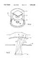
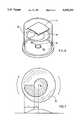
- FIGS. 1 and 2are respective front and side views of a helmet incorporating a helmet mounted display in accordance with a preferred embodiment of the invention
- FIG. 3is an unfolded drawing of the optical path of a display system of the preferred embodiment of FIGS. 1 and 2;
- FIGS. 4 and 5are schematic diagrams illustrating one method for producing a semi-reflecting surface according to a preferred embodiment of the invention.
- FIGS. 6 and 7are schematic diagrams illustrating a alternative preferred method for producing a semi-reflecting surface according to a preferred embodiment of the invention.
- FIGS. 1 and 2show respective front and side views of a helmet 10 in accordance with a preferred embodiment of the invention.
- Helmet 10comprises a body portion 12 of standard construction and a mostly transparent visor 14 rotationally attached to the sides of body portion 12 such that it can be rotated upwards and out of view of the wearers.
- Visor 14has, preferably, a substantially spherical shape and includes a partially-reflecting simi-transparent spherical portion 16, which will be described in more detail below, placed in the line of sight of the observer.
- Projection system 18for projecting information onto the semi-transparent portion 16 to form a helmet mounted display enabling the wearer to view the projection from system 18 superimposed on the outside scene.
- Projection system 18includes a display 20 having a substantially flat display source 22.
- Display 20can be for example a CRT display, a LED display, a plasma display, an electroluminescent display, a liquid crystal display or any other suitable display.
- Light from an image which is generated or formed at display source 22is reflected from a toroidal folding mirror 24, which may be either a front surface mirror or a reflection coating placed on the back surface of a suitable lens, via a lens 26 to a folding mirror 28.
- the imageafter reflection from mirror 28, passes through a preferably prismatic lens 30 to semi-transparent portion 16 whence it is reflected toward the eye of the wearer of the helmet.
- the path of the central ray of the imageis shown on FIGS. 1 and 2 by dotted line 32.
- Lens 30comprises a central, preferably prismatic portion 30A and two spherical portions 30B and 30C. It should be noted that, in a preferred embodiment of the invention, one of the spherical portions is placed at or near the tangential focus of surface 16 and the other spherical portion is placed at or near the sagittal focus of surface 16. This placement allows for separate adjustment of the focal lengths of the two reflection axes. Lens 30 acts as field optics for the system and partially corrects for the astigmatism caused by off-axis reflection from surface 16.
- Lens 26is designed to correct for some of the aberrations of the system.
- toroidal mirror 24compensates for the astigmatic effect of the off-axis reflection from surface 16, i.e., it focuses the light from source 22 at the tangential and sagittal focuses of surface 16.
- prismatic lens 30 and lens 26are placed at an angle to the optical axis of the system in order to aid in correcting for comma and spherical aberrations.
- the above described projection systemprovides an image of source 22 to the eye of the wearer which appears to be at infinity.
- a field flattenerat source 22 in order to overcome any residual minor aberrations in the optics to insure that the entire image is at infinity.
- the field flattenermay be, for example, a lens placed at the source 22 or it may be a curved fiber optic face plate which will provide the image on a curved rather than flat surface.
- source 22may be curved rather than flat.
- the semi-transparent portionis not uniformly reflecting.
- the central area of the semi-transparent portionhas the desired uniform reflection and the reflectivity is decreased from the central area to the edge of the semi-reflective portion so that the edge is not noticeable to the wearer.
- the present inventorshave found that a decreasing portion having a angle (as viewed by the wearer) of 50 mrad is sufficient to cause the edge effect to disappear where portion 16 has a reflectivity of 10%. For higher reflectivities larger decreasing portions are required-for example, 100 mrad at 30% reflectivities. In general an angle of 50-300 mrad is preferred, with about 130 mrad being especially preferred. Useful improvement is often achieved with angles as low as 50 mrad.
- FIGS. 4 and 5illustrate one method of producing a semi-reflecting coating having the desired edge.
- FIG. 4shows a vacuum system including a vacuum bell 38 containing visor 14. Within the vacuum bell is a heated boat 40 containing the coating material for the semi-transparent portion 16. Spaced from and between boat 40 and visor 14 is a mask 42 having an opening of the generally the same shape as the semi-transparent portion.
- the size of the opening and the spacing of mask relative to boat 40 and visor 14, as well as the size of the boatwill be determined by simple geometric considerations as illustrated in FIG. 5 taking into consideration the size of central area and the desired angle of the decreasing portion.
- portions of visor 14 adjacent to the center of the hole in mask 42will be subject to evaporation from the entire boat 40, while outlying portions will "see" less of the boat, and will have a thinner layer deposited on them.
- Lines 44indicate the portion of boat 40 (i.e., all of the boat) viewed by a point 46.
- Lines 48indicate that off-center point 50 still sees the entire boat while lines 52 show that point 54 sees only a portion of the boat and is therefore coated by a thinner film of material.
- a reflecting materialis used to coat a portion of the surface of visor 14 with a thin film so that the central coated portion is semi-transparent, then near the edges the amount of coating will be reduced, reducing the reflectivity at the edges.
- FIG. 6shows an vacuum coating system similar to that of FIG. 4, except that the stationary mask is replaced by a rotating mask 56 closely spaced from visor 14.
- the aperture in mask 56shown more clearly in FIG. 7 is not circularly symmetric and rotates about point 58.
- the central portion, marked “a” on the curve at the bottom of FIG. 7will be uniformly coated, while portions outside the central portion, marked “b” on the curve will have less coating the farther they are from the central portion, due to the decreased amount of time they view boat 40.
- the present inventionhas been described in conjunction with a helmet mounted display having a visor on which the projected images are displayed, the invention is also applicable to other types of viewers such as goggles and larger windows on which images are projected.
Landscapes
- Physics & Mathematics (AREA)
- General Physics & Mathematics (AREA)
- Optics & Photonics (AREA)
- Helmets And Other Head Coverings (AREA)
Abstract
Description
Claims (22)
Applications Claiming Priority (2)
| Application Number | Priority Date | Filing Date | Title |
|---|---|---|---|
| IL99420 | 1991-09-05 | ||
| IL9942091AIL99420A (en) | 1991-09-05 | 1991-09-05 | Helmet mounted display |
Publications (1)
| Publication Number | Publication Date |
|---|---|
| US5341242Atrue US5341242A (en) | 1994-08-23 |
Family
ID=11062874
Family Applications (1)
| Application Number | Title | Priority Date | Filing Date |
|---|---|---|---|
| US07/878,391Expired - LifetimeUS5341242A (en) | 1991-09-05 | 1992-05-04 | Helmet mounted display |
Country Status (5)
| Country | Link |
|---|---|
| US (1) | US5341242A (en) |
| EP (1) | EP0531121B1 (en) |
| AT (1) | ATE182010T1 (en) |
| DE (1) | DE69229528D1 (en) |
| IL (1) | IL99420A (en) |
Cited By (102)
| Publication number | Priority date | Publication date | Assignee | Title |
|---|---|---|---|---|
| US5576887A (en)* | 1995-06-22 | 1996-11-19 | Honeywell Inc. | Head gear display system using off-axis image sources |
| EP0744643A3 (en)* | 1995-05-25 | 1997-01-15 | Canon Kabushiki Kaisha | Optical system for head-up display |
| EP0777142A2 (en) | 1995-11-24 | 1997-06-04 | Vectop Ltd. | Adapter for extracting a portion of an image from an optical system or device |
| US5646785A (en)* | 1993-11-04 | 1997-07-08 | Elbit Ltd. | Helmet with wind resistant visor |
| US5706137A (en)* | 1992-09-22 | 1998-01-06 | Kelly; Shawn L. | Wide field of view imaging system |
| US5757339A (en)* | 1997-01-06 | 1998-05-26 | Xybernaut Corporation | Head mounted display |
| US5909325A (en)* | 1995-06-26 | 1999-06-01 | Olympus Optical Co., Ltd. | Image display apparatus |
| WO1999040470A1 (en)* | 1998-02-06 | 1999-08-12 | Rodenstock Präzisionsoptik Gmbh | Observation and mirroring device |
| DE19809711C1 (en)* | 1998-02-06 | 1999-11-18 | Rodenstock Praezisionsoptik Gm | Optical viewing device for head-up display or helmet-mounted display e.g. for aircraft pilot |
| US6061182A (en)* | 1996-11-21 | 2000-05-09 | Vectop Ltd. | Combiner for superimposing a display image on to an image of an external scene |
| US6215269B1 (en)* | 1996-05-21 | 2001-04-10 | Kent Gregg | Method of exposing a path on a curved, or otherwise irregularly shaped, surface |
| US20040162637A1 (en)* | 2002-07-25 | 2004-08-19 | Yulun Wang | Medical tele-robotic system with a master remote station with an arbitrator |
| US20040174129A1 (en)* | 2003-03-06 | 2004-09-09 | Yulun Wang | Medical tele-robotic system with a head worn device |
| US6847336B1 (en) | 1996-10-02 | 2005-01-25 | Jerome H. Lemelson | Selectively controllable heads-up display system |
| US20050125098A1 (en)* | 2003-12-09 | 2005-06-09 | Yulun Wang | Protocol for a remotely controlled videoconferencing robot |
| US20060082642A1 (en)* | 2002-07-25 | 2006-04-20 | Yulun Wang | Tele-robotic videoconferencing in a corporate environment |
| US20060205703A1 (en)* | 2003-01-23 | 2006-09-14 | Patel Pravin M | Stabilized steroid composition and method for its preparation |
| US20060250696A1 (en)* | 2005-05-03 | 2006-11-09 | Mcguire James P | Head mounted display devices |
| US7147338B2 (en) | 2001-04-09 | 2006-12-12 | Kent Gregg | Circuit on a curved, or otherwise irregularly shaped, surface, such as on a helmet to be worn on the head, including a fiber optic conductive path |
| US7158861B2 (en) | 2002-07-25 | 2007-01-02 | Intouch Technologies, Inc. | Tele-robotic system used to provide remote consultation services |
| US20070198130A1 (en)* | 2006-02-22 | 2007-08-23 | Yulun Wang | Graphical interface for a remote presence system |
| US20070291109A1 (en)* | 2006-06-15 | 2007-12-20 | Yulun Wang | Remote controlled mobile robot with auxillary input ports |
| US20080082211A1 (en)* | 2006-10-03 | 2008-04-03 | Yulun Wang | Remote presence display through remotely controlled robot |
| US20090055023A1 (en)* | 2007-08-23 | 2009-02-26 | Derek Walters | Telepresence robot with a printer |
| US7542209B2 (en) | 2004-09-01 | 2009-06-02 | Optical Research Associates | Compact head mounted display devices with tilted/decentered lens element |
| US20090225396A1 (en)* | 2008-03-07 | 2009-09-10 | Qualcomm Mems Technologies, Inc. | System and methods for tiling display panels |
| US20090231722A1 (en)* | 2008-03-13 | 2009-09-17 | Day & Night Display Systems, Llc | Visor heads-up display |
| US20100019715A1 (en)* | 2008-04-17 | 2010-01-28 | David Bjorn Roe | Mobile tele-presence system with a microphone system |
| US20100115418A1 (en)* | 2004-02-26 | 2010-05-06 | Yulun Wang | Graphical interface for a remote presence system |
| US20100165443A1 (en)* | 2004-09-27 | 2010-07-01 | Qualcomm Mems Technologies, Inc. | Systems and methods using interferometric optical modulators and diffusers |
| US20100214642A1 (en)* | 1995-11-06 | 2010-08-26 | Miles Mark W | Method and device for modulating light with optical compensation |
| US20100268383A1 (en)* | 2009-04-17 | 2010-10-21 | Yulun Wang | Tele-presence robot system with software modularity, projector and laser pointer |
| US7848001B2 (en) | 1994-05-05 | 2010-12-07 | Qualcomm Mems Technologies, Inc. | Method and system for interferometric modulation in projection or peripheral devices |
| US20100309103A1 (en)* | 2004-09-27 | 2010-12-09 | Qualcomm Mems Technologies, Inc. | Methods and devices for lighting displays |
| US20110055993A1 (en)* | 2009-09-08 | 2011-03-10 | Thales | Helmet including a protective shell with variable rigidity |
| US8045252B2 (en) | 2004-02-03 | 2011-10-25 | Qualcomm Mems Technologies, Inc. | Spatial light modulator with integrated optical compensation structure |
| US8061882B2 (en) | 2006-10-06 | 2011-11-22 | Qualcomm Mems Technologies, Inc. | Illumination device with built-in light coupler |
| US8068710B2 (en) | 2007-12-07 | 2011-11-29 | Qualcomm Mems Technologies, Inc. | Decoupled holographic film and diffuser |
| US8077963B2 (en) | 2004-07-13 | 2011-12-13 | Yulun Wang | Mobile robot with a head-based movement mapping scheme |
| US8179418B2 (en) | 2008-04-14 | 2012-05-15 | Intouch Technologies, Inc. | Robotic based health care system |
| US8340819B2 (en) | 2008-09-18 | 2012-12-25 | Intouch Technologies, Inc. | Mobile videoconferencing robot system with network adaptive driving |
| US8346048B2 (en) | 2008-05-28 | 2013-01-01 | Qualcomm Mems Technologies, Inc. | Front light devices and methods of fabrication thereof |
| US8384755B2 (en) | 2009-08-26 | 2013-02-26 | Intouch Technologies, Inc. | Portable remote presence robot |
| US8463435B2 (en) | 2008-11-25 | 2013-06-11 | Intouch Technologies, Inc. | Server connectivity control for tele-presence robot |
| US8670171B2 (en) | 2010-10-18 | 2014-03-11 | Qualcomm Mems Technologies, Inc. | Display having an embedded microlens array |
| US8670017B2 (en) | 2010-03-04 | 2014-03-11 | Intouch Technologies, Inc. | Remote presence system including a cart that supports a robot face and an overhead camera |
| US20140071294A1 (en)* | 2012-09-12 | 2014-03-13 | Bae Systems Information And Electronic Systems Integration Inc. | Face mounted extreme environment thermal sensor system |
| US8718837B2 (en) | 2011-01-28 | 2014-05-06 | Intouch Technologies | Interfacing with a mobile telepresence robot |
| US20140184477A1 (en)* | 2012-12-27 | 2014-07-03 | Seiko Epson Corporation | Head-mounted display |
| US8836751B2 (en) | 2011-11-08 | 2014-09-16 | Intouch Technologies, Inc. | Tele-presence system with a user interface that displays different communication links |
| US8849679B2 (en) | 2006-06-15 | 2014-09-30 | Intouch Technologies, Inc. | Remote controlled robot system that provides medical images |
| US8849680B2 (en) | 2009-01-29 | 2014-09-30 | Intouch Technologies, Inc. | Documentation through a remote presence robot |
| US8872085B2 (en) | 2006-10-06 | 2014-10-28 | Qualcomm Mems Technologies, Inc. | Display device having front illuminator with turning features |
| US8892260B2 (en) | 2007-03-20 | 2014-11-18 | Irobot Corporation | Mobile robot for telecommunication |
| US8902278B2 (en) | 2012-04-11 | 2014-12-02 | Intouch Technologies, Inc. | Systems and methods for visualizing and managing telepresence devices in healthcare networks |
| US8928967B2 (en) | 1998-04-08 | 2015-01-06 | Qualcomm Mems Technologies, Inc. | Method and device for modulating light |
| US8930019B2 (en) | 2010-12-30 | 2015-01-06 | Irobot Corporation | Mobile human interface robot |
| US8935005B2 (en) | 2010-05-20 | 2015-01-13 | Irobot Corporation | Operating a mobile robot |
| US8971675B2 (en) | 2006-01-13 | 2015-03-03 | Qualcomm Mems Technologies, Inc. | Interconnect structure for MEMS device |
| US8979349B2 (en) | 2009-05-29 | 2015-03-17 | Qualcomm Mems Technologies, Inc. | Illumination devices and methods of fabrication thereof |
| US8996165B2 (en) | 2008-10-21 | 2015-03-31 | Intouch Technologies, Inc. | Telepresence robot with a camera boom |
| US9014848B2 (en) | 2010-05-20 | 2015-04-21 | Irobot Corporation | Mobile robot system |
| US9019183B2 (en) | 2006-10-06 | 2015-04-28 | Qualcomm Mems Technologies, Inc. | Optical loss structure integrated in an illumination apparatus |
| US9025235B2 (en) | 2002-12-25 | 2015-05-05 | Qualcomm Mems Technologies, Inc. | Optical interference type of color display having optical diffusion layer between substrate and electrode |
| US20150130945A1 (en)* | 2013-11-14 | 2015-05-14 | Chiun Mai Communication Systems, Inc. | Smart helmet |
| US9098611B2 (en) | 2012-11-26 | 2015-08-04 | Intouch Technologies, Inc. | Enhanced video interaction for a user interface of a telepresence network |
| US9110289B2 (en) | 1998-04-08 | 2015-08-18 | Qualcomm Mems Technologies, Inc. | Device for modulating light with multiple electrodes |
| US9138891B2 (en) | 2008-11-25 | 2015-09-22 | Intouch Technologies, Inc. | Server connectivity control for tele-presence robot |
| US9160783B2 (en) | 2007-05-09 | 2015-10-13 | Intouch Technologies, Inc. | Robot system that operates through a network firewall |
| US9174342B2 (en) | 2012-05-22 | 2015-11-03 | Intouch Technologies, Inc. | Social behavior rules for a medical telepresence robot |
| US9193065B2 (en) | 2008-07-10 | 2015-11-24 | Intouch Technologies, Inc. | Docking system for a tele-presence robot |
| US9198728B2 (en) | 2005-09-30 | 2015-12-01 | Intouch Technologies, Inc. | Multi-camera mobile teleconferencing platform |
| US9251313B2 (en) | 2012-04-11 | 2016-02-02 | Intouch Technologies, Inc. | Systems and methods for visualizing and managing telepresence devices in healthcare networks |
| US9264664B2 (en) | 2010-12-03 | 2016-02-16 | Intouch Technologies, Inc. | Systems and methods for dynamic bandwidth allocation |
| US9323250B2 (en) | 2011-01-28 | 2016-04-26 | Intouch Technologies, Inc. | Time-dependent navigation of telepresence robots |
| WO2016071352A1 (en) | 2014-11-06 | 2016-05-12 | Thales | Head-borne viewing system comprising crossed optics |
| US9361021B2 (en) | 2012-05-22 | 2016-06-07 | Irobot Corporation | Graphical user interfaces including touchpad driving interfaces for telemedicine devices |
| US9498886B2 (en) | 2010-05-20 | 2016-11-22 | Irobot Corporation | Mobile human interface robot |
| US20170143068A1 (en)* | 2015-11-25 | 2017-05-25 | Ming Zhang | Intelligent Safety Helmet with Front Play of Rearview |
| US20170212350A1 (en)* | 2016-01-21 | 2017-07-27 | Coretronic Corporation | Head-mounted display apparatus |
| US9842192B2 (en) | 2008-07-11 | 2017-12-12 | Intouch Technologies, Inc. | Tele-presence robot system with multi-cast features |
| US9974612B2 (en) | 2011-05-19 | 2018-05-22 | Intouch Technologies, Inc. | Enhanced diagnostics for a telepresence robot |
| US10120194B2 (en) | 2016-01-22 | 2018-11-06 | Corning Incorporated | Wide field personal display |
| US20190142327A1 (en)* | 2016-01-13 | 2019-05-16 | REBIScan, Inc. | Method and apparatus for measuring saccadic latency |
| US10343283B2 (en) | 2010-05-24 | 2019-07-09 | Intouch Technologies, Inc. | Telepresence robot system that can be accessed by a cellular phone |
| US10488660B2 (en) | 2008-03-13 | 2019-11-26 | Everysight Ltd. | Wearable optical display system for unobstructed viewing |
| US10769739B2 (en) | 2011-04-25 | 2020-09-08 | Intouch Technologies, Inc. | Systems and methods for management of information among medical providers and facilities |
| US10808882B2 (en) | 2010-05-26 | 2020-10-20 | Intouch Technologies, Inc. | Tele-robotic system with a robot face placed on a chair |
| US10875182B2 (en) | 2008-03-20 | 2020-12-29 | Teladoc Health, Inc. | Remote presence system mounted to operating room hardware |
| US10976551B2 (en) | 2017-08-30 | 2021-04-13 | Corning Incorporated | Wide field personal display device |
| US11154981B2 (en) | 2010-02-04 | 2021-10-26 | Teladoc Health, Inc. | Robot user interface for telepresence robot system |
| US11256094B2 (en) | 2008-03-13 | 2022-02-22 | Everysight Ltd. | Wearable optical display system for unobstructed viewing |
| US11389064B2 (en) | 2018-04-27 | 2022-07-19 | Teladoc Health, Inc. | Telehealth cart that supports a removable tablet with seamless audio/video switching |
| US11399153B2 (en) | 2009-08-26 | 2022-07-26 | Teladoc Health, Inc. | Portable telepresence apparatus |
| US11493773B2 (en) | 2021-06-07 | 2022-11-08 | Panamorph, Inc. | Near-eye display system |
| US11513349B2 (en) | 2008-03-13 | 2022-11-29 | Everysight Ltd. | Optical see-through (OST) near-eye display (NED) system integrating ophthalmic correction |
| US11636944B2 (en) | 2017-08-25 | 2023-04-25 | Teladoc Health, Inc. | Connectivity infrastructure for a telehealth platform |
| US11742094B2 (en) | 2017-07-25 | 2023-08-29 | Teladoc Health, Inc. | Modular telehealth cart with thermal imaging and touch screen user interface |
| US11862302B2 (en) | 2017-04-24 | 2024-01-02 | Teladoc Health, Inc. | Automated transcription and documentation of tele-health encounters |
| US12093036B2 (en) | 2011-01-21 | 2024-09-17 | Teladoc Health, Inc. | Telerobotic system with a dual application screen presentation |
| US12204096B2 (en) | 2021-06-07 | 2025-01-21 | Panamorph, Inc. | Near-eye display system |
| US12224059B2 (en) | 2011-02-16 | 2025-02-11 | Teladoc Health, Inc. | Systems and methods for network-based counseling |
Families Citing this family (11)
| Publication number | Priority date | Publication date | Assignee | Title |
|---|---|---|---|---|
| US5384654A (en)* | 1993-05-10 | 1995-01-24 | Olympus Optical Co., Ltd. | Image observation device |
| JP3392929B2 (en)* | 1994-02-07 | 2003-03-31 | オリンパス光学工業株式会社 | Video display device |
| WO1997034182A1 (en)* | 1996-03-11 | 1997-09-18 | Seiko Epson Corporation | Head-mounted display |
| FR2766931B1 (en)* | 1997-08-01 | 1999-10-15 | Sextant Avionique | OPTICAL DEVICE FOR A HELMET SIGHT COMPRISING AN ASPHERIC MIRROR |
| FR2769721B1 (en)* | 1997-10-10 | 2001-01-26 | Sextant Avionique | OPTICAL DEVICE FOR A HELMET SIGHT COMPRISING A MANGIN MIRROR |
| FR2775358B1 (en)* | 1998-02-20 | 2003-06-20 | Sextant Avionique | OPTICAL DEVICE FOR A HELMET SIGHT COMPRISING A TUBULAR MIRROR |
| GB2348068A (en)* | 1999-03-16 | 2000-09-20 | Keeler Ltd | Image detection system |
| FR2810412B1 (en)* | 2000-06-19 | 2003-08-01 | Aerospatiale Matra Missiles | VISUALIZATION DEVICE MOUNTED ON A HELMET |
| FR2824921B1 (en)* | 2001-05-15 | 2003-09-19 | Thomson Csf | REDUCED OVERALL OPTICAL ARCHITECTURE FOR LARGE FIELD HELMET VIEWFINDER |
| FR2980858B1 (en)* | 2011-10-04 | 2014-03-21 | Optinvent | OPTICAL DEVICE FOR PROJECTING IMAGES WITH ASPHERIC MIRRORS PLACED HEAD-SPOT |
| FR3156549A1 (en)* | 2023-12-06 | 2025-06-13 | Eyelights | Optical design process for a head-up display and associated head-up display |
Citations (14)
| Publication number | Priority date | Publication date | Assignee | Title |
|---|---|---|---|---|
| US3302515A (en)* | 1963-05-28 | 1967-02-07 | Alos Ag | Projection apparatus or system provided with concave reflector |
| US3787109A (en)* | 1972-06-28 | 1974-01-22 | Honeywell Inc | Inside helmet sight apparatus |
| US3923370A (en)* | 1974-10-15 | 1975-12-02 | Honeywell Inc | Head mounted displays |
| US4026641A (en)* | 1975-12-30 | 1977-05-31 | The United States Of America As Represented By The Secretary Of The Army | Toric reflector display |
| GB1489323A (en)* | 1975-01-23 | 1977-10-19 | Hughes Aircraft Co | Optical display systems utilizing holographic lenses |
| US4081209A (en)* | 1975-04-29 | 1978-03-28 | Elliott Brothers (London) Limited | Headgear with spherical semi-reflecting surface |
| DE2730635A1 (en)* | 1977-07-07 | 1979-01-25 | Gelhard | Rear view mirror esp. for cycling, skiing, roller-stating etc. - is fastened to safety helmet on wearer's head and stuck to wind shield |
| US4364636A (en)* | 1979-11-09 | 1982-12-21 | Elliott Brothers (London) Limited | Helmet mounted sight with fixed display and pivotal arm |
| FR2569863A1 (en)* | 1984-09-04 | 1986-03-07 | Saint Gobain Vitrage | Glass with a semireflecting surface portion, its method of manufacture and its application as a windscreen |
| US4722601A (en)* | 1983-07-23 | 1988-02-02 | Ferranti Plc | Apparatus for determining the direction of a line of sight |
| US4761056A (en)* | 1987-03-27 | 1988-08-02 | Kaiser Aerospace And Electronics Corporation | Compact helmet mounted display |
| EP0303742A1 (en)* | 1987-08-13 | 1989-02-22 | KAISER AEROSPACE & ELECTRONICS CORPORATION | Head-up display |
| US4859030A (en)* | 1987-07-29 | 1989-08-22 | Honeywell, Inc. | Helmet mounted display with improved brightness |
| US4878046A (en)* | 1987-07-30 | 1989-10-31 | United Technologies Corporation | Mounting a cathode ray tube for a heads-up display system |
- 1991
- 1991-09-05ILIL9942091Apatent/IL99420A/ennot_activeIP Right Cessation
- 1992
- 1992-05-04USUS07/878,391patent/US5341242A/ennot_activeExpired - Lifetime
- 1992-09-03ATAT92307983Tpatent/ATE182010T1/ennot_activeIP Right Cessation
- 1992-09-03DEDE69229528Tpatent/DE69229528D1/ennot_activeExpired - Lifetime
- 1992-09-03EPEP92307983Apatent/EP0531121B1/ennot_activeExpired - Lifetime
Patent Citations (14)
| Publication number | Priority date | Publication date | Assignee | Title |
|---|---|---|---|---|
| US3302515A (en)* | 1963-05-28 | 1967-02-07 | Alos Ag | Projection apparatus or system provided with concave reflector |
| US3787109A (en)* | 1972-06-28 | 1974-01-22 | Honeywell Inc | Inside helmet sight apparatus |
| US3923370A (en)* | 1974-10-15 | 1975-12-02 | Honeywell Inc | Head mounted displays |
| GB1489323A (en)* | 1975-01-23 | 1977-10-19 | Hughes Aircraft Co | Optical display systems utilizing holographic lenses |
| US4081209A (en)* | 1975-04-29 | 1978-03-28 | Elliott Brothers (London) Limited | Headgear with spherical semi-reflecting surface |
| US4026641A (en)* | 1975-12-30 | 1977-05-31 | The United States Of America As Represented By The Secretary Of The Army | Toric reflector display |
| DE2730635A1 (en)* | 1977-07-07 | 1979-01-25 | Gelhard | Rear view mirror esp. for cycling, skiing, roller-stating etc. - is fastened to safety helmet on wearer's head and stuck to wind shield |
| US4364636A (en)* | 1979-11-09 | 1982-12-21 | Elliott Brothers (London) Limited | Helmet mounted sight with fixed display and pivotal arm |
| US4722601A (en)* | 1983-07-23 | 1988-02-02 | Ferranti Plc | Apparatus for determining the direction of a line of sight |
| FR2569863A1 (en)* | 1984-09-04 | 1986-03-07 | Saint Gobain Vitrage | Glass with a semireflecting surface portion, its method of manufacture and its application as a windscreen |
| US4761056A (en)* | 1987-03-27 | 1988-08-02 | Kaiser Aerospace And Electronics Corporation | Compact helmet mounted display |
| US4859030A (en)* | 1987-07-29 | 1989-08-22 | Honeywell, Inc. | Helmet mounted display with improved brightness |
| US4878046A (en)* | 1987-07-30 | 1989-10-31 | United Technologies Corporation | Mounting a cathode ray tube for a heads-up display system |
| EP0303742A1 (en)* | 1987-08-13 | 1989-02-22 | KAISER AEROSPACE & ELECTRONICS CORPORATION | Head-up display |
Non-Patent Citations (2)
| Title |
|---|
| J. G. Droessler et al, "Tilted Cat Helmet-Mounted Display", Optical Engineering, vol. 29, No. 8, Aug. 1990, Bellingham US pp. 849-854. |
| J. G. Droessler et al, Tilted Cat Helmet Mounted Display , Optical Engineering, vol. 29, No. 8, Aug. 1990, Bellingham US pp. 849 854.* |
Cited By (205)
| Publication number | Priority date | Publication date | Assignee | Title |
|---|---|---|---|---|
| USRE39643E1 (en)* | 1992-09-22 | 2007-05-22 | Kelly Shawn L | Wide field of view imaging system |
| US5706137A (en)* | 1992-09-22 | 1998-01-06 | Kelly; Shawn L. | Wide field of view imaging system |
| US5646785A (en)* | 1993-11-04 | 1997-07-08 | Elbit Ltd. | Helmet with wind resistant visor |
| US8284474B2 (en) | 1994-05-05 | 2012-10-09 | Qualcomm Mems Technologies, Inc. | Method and system for interferometric modulation in projection or peripheral devices |
| US7848001B2 (en) | 1994-05-05 | 2010-12-07 | Qualcomm Mems Technologies, Inc. | Method and system for interferometric modulation in projection or peripheral devices |
| US5687025A (en)* | 1995-05-25 | 1997-11-11 | Canon Kabushiki Kaisha | Image display apparatus and image pickup apparatus |
| EP0744643A3 (en)* | 1995-05-25 | 1997-01-15 | Canon Kabushiki Kaisha | Optical system for head-up display |
| US5576887A (en)* | 1995-06-22 | 1996-11-19 | Honeywell Inc. | Head gear display system using off-axis image sources |
| US5909325A (en)* | 1995-06-26 | 1999-06-01 | Olympus Optical Co., Ltd. | Image display apparatus |
| US8422108B2 (en) | 1995-11-06 | 2013-04-16 | Qualcomm Mems Technologies, Inc. | Method and device for modulating light with optical compensation |
| US20100214642A1 (en)* | 1995-11-06 | 2010-08-26 | Miles Mark W | Method and device for modulating light with optical compensation |
| EP0777142A2 (en) | 1995-11-24 | 1997-06-04 | Vectop Ltd. | Adapter for extracting a portion of an image from an optical system or device |
| US5742434A (en)* | 1995-11-24 | 1998-04-21 | Vectop Ltd. | Adapter for extracting a portion of an image from an optical system or device |
| US6215269B1 (en)* | 1996-05-21 | 2001-04-10 | Kent Gregg | Method of exposing a path on a curved, or otherwise irregularly shaped, surface |
| US6847336B1 (en) | 1996-10-02 | 2005-01-25 | Jerome H. Lemelson | Selectively controllable heads-up display system |
| US20050206583A1 (en)* | 1996-10-02 | 2005-09-22 | Lemelson Jerome H | Selectively controllable heads-up display system |
| US6061182A (en)* | 1996-11-21 | 2000-05-09 | Vectop Ltd. | Combiner for superimposing a display image on to an image of an external scene |
| US5757339A (en)* | 1997-01-06 | 1998-05-26 | Xybernaut Corporation | Head mounted display |
| DE19809711C1 (en)* | 1998-02-06 | 1999-11-18 | Rodenstock Praezisionsoptik Gm | Optical viewing device for head-up display or helmet-mounted display e.g. for aircraft pilot |
| WO1999040470A1 (en)* | 1998-02-06 | 1999-08-12 | Rodenstock Präzisionsoptik Gmbh | Observation and mirroring device |
| US9110289B2 (en) | 1998-04-08 | 2015-08-18 | Qualcomm Mems Technologies, Inc. | Device for modulating light with multiple electrodes |
| US8928967B2 (en) | 1998-04-08 | 2015-01-06 | Qualcomm Mems Technologies, Inc. | Method and device for modulating light |
| US7147338B2 (en) | 2001-04-09 | 2006-12-12 | Kent Gregg | Circuit on a curved, or otherwise irregularly shaped, surface, such as on a helmet to be worn on the head, including a fiber optic conductive path |
| US20070021871A1 (en)* | 2002-07-25 | 2007-01-25 | Yulun Wang | Medical tele-robotic system |
| US9849593B2 (en) | 2002-07-25 | 2017-12-26 | Intouch Technologies, Inc. | Medical tele-robotic system with a master remote station with an arbitrator |
| US20040162637A1 (en)* | 2002-07-25 | 2004-08-19 | Yulun Wang | Medical tele-robotic system with a master remote station with an arbitrator |
| US8209051B2 (en) | 2002-07-25 | 2012-06-26 | Intouch Technologies, Inc. | Medical tele-robotic system |
| US20060082642A1 (en)* | 2002-07-25 | 2006-04-20 | Yulun Wang | Tele-robotic videoconferencing in a corporate environment |
| US7289883B2 (en) | 2002-07-25 | 2007-10-30 | Intouch Technologies, Inc. | Apparatus and method for patient rounding with a remote controlled robot |
| US7158861B2 (en) | 2002-07-25 | 2007-01-02 | Intouch Technologies, Inc. | Tele-robotic system used to provide remote consultation services |
| US20080029536A1 (en)* | 2002-07-25 | 2008-02-07 | Intouch Technologies, Inc. | Medical tele-robotic system |
| US10315312B2 (en) | 2002-07-25 | 2019-06-11 | Intouch Technologies, Inc. | Medical tele-robotic system with a master remote station with an arbitrator |
| US20080201017A1 (en)* | 2002-07-25 | 2008-08-21 | Yulun Wang | Medical tele-robotic system |
| USRE45870E1 (en) | 2002-07-25 | 2016-01-26 | Intouch Technologies, Inc. | Apparatus and method for patient rounding with a remote controlled robot |
| US7593030B2 (en) | 2002-07-25 | 2009-09-22 | Intouch Technologies, Inc. | Tele-robotic videoconferencing in a corporate environment |
| US8515577B2 (en) | 2002-07-25 | 2013-08-20 | Yulun Wang | Medical tele-robotic system with a master remote station with an arbitrator |
| US20070112464A1 (en)* | 2002-07-25 | 2007-05-17 | Yulun Wang | Apparatus and method for patient rounding with a remote controlled robot |
| US9025235B2 (en) | 2002-12-25 | 2015-05-05 | Qualcomm Mems Technologies, Inc. | Optical interference type of color display having optical diffusion layer between substrate and electrode |
| US20060205703A1 (en)* | 2003-01-23 | 2006-09-14 | Patel Pravin M | Stabilized steroid composition and method for its preparation |
| US7262573B2 (en)* | 2003-03-06 | 2007-08-28 | Intouch Technologies, Inc. | Medical tele-robotic system with a head worn device |
| US20040174129A1 (en)* | 2003-03-06 | 2004-09-09 | Yulun Wang | Medical tele-robotic system with a head worn device |
| US9956690B2 (en) | 2003-12-09 | 2018-05-01 | Intouch Technologies, Inc. | Protocol for a remotely controlled videoconferencing robot |
| US20050125098A1 (en)* | 2003-12-09 | 2005-06-09 | Yulun Wang | Protocol for a remotely controlled videoconferencing robot |
| US9375843B2 (en) | 2003-12-09 | 2016-06-28 | Intouch Technologies, Inc. | Protocol for a remotely controlled videoconferencing robot |
| US7813836B2 (en) | 2003-12-09 | 2010-10-12 | Intouch Technologies, Inc. | Protocol for a remotely controlled videoconferencing robot |
| US10882190B2 (en) | 2003-12-09 | 2021-01-05 | Teladoc Health, Inc. | Protocol for a remotely controlled videoconferencing robot |
| US9019590B2 (en) | 2004-02-03 | 2015-04-28 | Qualcomm Mems Technologies, Inc. | Spatial light modulator with integrated optical compensation structure |
| US8111445B2 (en) | 2004-02-03 | 2012-02-07 | Qualcomm Mems Technologies, Inc. | Spatial light modulator with integrated optical compensation structure |
| US8045252B2 (en) | 2004-02-03 | 2011-10-25 | Qualcomm Mems Technologies, Inc. | Spatial light modulator with integrated optical compensation structure |
| US20100115418A1 (en)* | 2004-02-26 | 2010-05-06 | Yulun Wang | Graphical interface for a remote presence system |
| US9610685B2 (en) | 2004-02-26 | 2017-04-04 | Intouch Technologies, Inc. | Graphical interface for a remote presence system |
| US10241507B2 (en) | 2004-07-13 | 2019-03-26 | Intouch Technologies, Inc. | Mobile robot with a head-based movement mapping scheme |
| US8077963B2 (en) | 2004-07-13 | 2011-12-13 | Yulun Wang | Mobile robot with a head-based movement mapping scheme |
| US8983174B2 (en) | 2004-07-13 | 2015-03-17 | Intouch Technologies, Inc. | Mobile robot with a head-based movement mapping scheme |
| US8401275B2 (en) | 2004-07-13 | 2013-03-19 | Intouch Technologies, Inc. | Mobile robot with a head-based movement mapping scheme |
| US9766624B2 (en) | 2004-07-13 | 2017-09-19 | Intouch Technologies, Inc. | Mobile robot with a head-based movement mapping scheme |
| US7542209B2 (en) | 2004-09-01 | 2009-06-02 | Optical Research Associates | Compact head mounted display devices with tilted/decentered lens element |
| US20100165443A1 (en)* | 2004-09-27 | 2010-07-01 | Qualcomm Mems Technologies, Inc. | Systems and methods using interferometric optical modulators and diffusers |
| US20100309103A1 (en)* | 2004-09-27 | 2010-12-09 | Qualcomm Mems Technologies, Inc. | Methods and devices for lighting displays |
| US8013831B2 (en) | 2004-09-27 | 2011-09-06 | Qualcomm Mems Technologies, Inc. | Methods and devices for lighting displays |
| US7944602B2 (en) | 2004-09-27 | 2011-05-17 | Qualcomm Mems Technologies, Inc. | Systems and methods using interferometric optical modulators and diffusers |
| US20060250696A1 (en)* | 2005-05-03 | 2006-11-09 | Mcguire James P | Head mounted display devices |
| US7450310B2 (en) | 2005-05-03 | 2008-11-11 | Optical Research Associates | Head mounted display devices |
| US9198728B2 (en) | 2005-09-30 | 2015-12-01 | Intouch Technologies, Inc. | Multi-camera mobile teleconferencing platform |
| US10259119B2 (en) | 2005-09-30 | 2019-04-16 | Intouch Technologies, Inc. | Multi-camera mobile teleconferencing platform |
| US8971675B2 (en) | 2006-01-13 | 2015-03-03 | Qualcomm Mems Technologies, Inc. | Interconnect structure for MEMS device |
| US20070198130A1 (en)* | 2006-02-22 | 2007-08-23 | Yulun Wang | Graphical interface for a remote presence system |
| US7769492B2 (en) | 2006-02-22 | 2010-08-03 | Intouch Technologies, Inc. | Graphical interface for a remote presence system |
| US8849679B2 (en) | 2006-06-15 | 2014-09-30 | Intouch Technologies, Inc. | Remote controlled robot system that provides medical images |
| US20070291109A1 (en)* | 2006-06-15 | 2007-12-20 | Yulun Wang | Remote controlled mobile robot with auxillary input ports |
| US20080082211A1 (en)* | 2006-10-03 | 2008-04-03 | Yulun Wang | Remote presence display through remotely controlled robot |
| US7761185B2 (en) | 2006-10-03 | 2010-07-20 | Intouch Technologies, Inc. | Remote presence display through remotely controlled robot |
| US9019183B2 (en) | 2006-10-06 | 2015-04-28 | Qualcomm Mems Technologies, Inc. | Optical loss structure integrated in an illumination apparatus |
| US8061882B2 (en) | 2006-10-06 | 2011-11-22 | Qualcomm Mems Technologies, Inc. | Illumination device with built-in light coupler |
| US8872085B2 (en) | 2006-10-06 | 2014-10-28 | Qualcomm Mems Technologies, Inc. | Display device having front illuminator with turning features |
| US9296109B2 (en) | 2007-03-20 | 2016-03-29 | Irobot Corporation | Mobile robot for telecommunication |
| US8892260B2 (en) | 2007-03-20 | 2014-11-18 | Irobot Corporation | Mobile robot for telecommunication |
| US9160783B2 (en) | 2007-05-09 | 2015-10-13 | Intouch Technologies, Inc. | Robot system that operates through a network firewall |
| US10682763B2 (en) | 2007-05-09 | 2020-06-16 | Intouch Technologies, Inc. | Robot system that operates through a network firewall |
| US8116910B2 (en) | 2007-08-23 | 2012-02-14 | Intouch Technologies, Inc. | Telepresence robot with a printer |
| US20090055023A1 (en)* | 2007-08-23 | 2009-02-26 | Derek Walters | Telepresence robot with a printer |
| US8798425B2 (en) | 2007-12-07 | 2014-08-05 | Qualcomm Mems Technologies, Inc. | Decoupled holographic film and diffuser |
| US8068710B2 (en) | 2007-12-07 | 2011-11-29 | Qualcomm Mems Technologies, Inc. | Decoupled holographic film and diffuser |
| US20090225396A1 (en)* | 2008-03-07 | 2009-09-10 | Qualcomm Mems Technologies, Inc. | System and methods for tiling display panels |
| US7948672B2 (en) | 2008-03-07 | 2011-05-24 | Qualcomm Mems Technologies, Inc. | System and methods for tiling display panels |
| US11256094B2 (en) | 2008-03-13 | 2022-02-22 | Everysight Ltd. | Wearable optical display system for unobstructed viewing |
| US20090231722A1 (en)* | 2008-03-13 | 2009-09-17 | Day & Night Display Systems, Llc | Visor heads-up display |
| US11513349B2 (en) | 2008-03-13 | 2022-11-29 | Everysight Ltd. | Optical see-through (OST) near-eye display (NED) system integrating ophthalmic correction |
| US10488660B2 (en) | 2008-03-13 | 2019-11-26 | Everysight Ltd. | Wearable optical display system for unobstructed viewing |
| US7791809B2 (en)* | 2008-03-13 | 2010-09-07 | Day And Night Display Systems, Inc. | Visor heads-up display |
| US20100315720A1 (en)* | 2008-03-13 | 2010-12-16 | Day And Night Displays Systems, Llc | Visor heads-up display |
| US8970962B2 (en) | 2008-03-13 | 2015-03-03 | Elbit Systems Ltd | Visor heads-up display |
| US11787060B2 (en) | 2008-03-20 | 2023-10-17 | Teladoc Health, Inc. | Remote presence system mounted to operating room hardware |
| US10875182B2 (en) | 2008-03-20 | 2020-12-29 | Teladoc Health, Inc. | Remote presence system mounted to operating room hardware |
| US10471588B2 (en) | 2008-04-14 | 2019-11-12 | Intouch Technologies, Inc. | Robotic based health care system |
| US11472021B2 (en) | 2008-04-14 | 2022-10-18 | Teladoc Health, Inc. | Robotic based health care system |
| US8179418B2 (en) | 2008-04-14 | 2012-05-15 | Intouch Technologies, Inc. | Robotic based health care system |
| US20100019715A1 (en)* | 2008-04-17 | 2010-01-28 | David Bjorn Roe | Mobile tele-presence system with a microphone system |
| US8170241B2 (en) | 2008-04-17 | 2012-05-01 | Intouch Technologies, Inc. | Mobile tele-presence system with a microphone system |
| US8346048B2 (en) | 2008-05-28 | 2013-01-01 | Qualcomm Mems Technologies, Inc. | Front light devices and methods of fabrication thereof |
| US9193065B2 (en) | 2008-07-10 | 2015-11-24 | Intouch Technologies, Inc. | Docking system for a tele-presence robot |
| US10493631B2 (en) | 2008-07-10 | 2019-12-03 | Intouch Technologies, Inc. | Docking system for a tele-presence robot |
| US10878960B2 (en) | 2008-07-11 | 2020-12-29 | Teladoc Health, Inc. | Tele-presence robot system with multi-cast features |
| US9842192B2 (en) | 2008-07-11 | 2017-12-12 | Intouch Technologies, Inc. | Tele-presence robot system with multi-cast features |
| US8340819B2 (en) | 2008-09-18 | 2012-12-25 | Intouch Technologies, Inc. | Mobile videoconferencing robot system with network adaptive driving |
| US9429934B2 (en) | 2008-09-18 | 2016-08-30 | Intouch Technologies, Inc. | Mobile videoconferencing robot system with network adaptive driving |
| US8996165B2 (en) | 2008-10-21 | 2015-03-31 | Intouch Technologies, Inc. | Telepresence robot with a camera boom |
| US8463435B2 (en) | 2008-11-25 | 2013-06-11 | Intouch Technologies, Inc. | Server connectivity control for tele-presence robot |
| US9138891B2 (en) | 2008-11-25 | 2015-09-22 | Intouch Technologies, Inc. | Server connectivity control for tele-presence robot |
| US10059000B2 (en) | 2008-11-25 | 2018-08-28 | Intouch Technologies, Inc. | Server connectivity control for a tele-presence robot |
| US10875183B2 (en) | 2008-11-25 | 2020-12-29 | Teladoc Health, Inc. | Server connectivity control for tele-presence robot |
| US12138808B2 (en) | 2008-11-25 | 2024-11-12 | Teladoc Health, Inc. | Server connectivity control for tele-presence robots |
| US8849680B2 (en) | 2009-01-29 | 2014-09-30 | Intouch Technologies, Inc. | Documentation through a remote presence robot |
| WO2010105201A1 (en)* | 2009-03-13 | 2010-09-16 | Day & Night Display Systems, Llc | Visor heads-up display |
| EP2406683A4 (en)* | 2009-03-13 | 2012-09-05 | Day & Night Display Systems Llc | DISPLAY DEVICE HEAD HIGH VISOR |
| JP2012520487A (en)* | 2009-03-13 | 2012-09-06 | デイ アンド ナイト ディスプレイ システムズ エルエルシー | Visor type head-up display |
| US8897920B2 (en) | 2009-04-17 | 2014-11-25 | Intouch Technologies, Inc. | Tele-presence robot system with software modularity, projector and laser pointer |
| US20100268383A1 (en)* | 2009-04-17 | 2010-10-21 | Yulun Wang | Tele-presence robot system with software modularity, projector and laser pointer |
| US10969766B2 (en) | 2009-04-17 | 2021-04-06 | Teladoc Health, Inc. | Tele-presence robot system with software modularity, projector and laser pointer |
| US8979349B2 (en) | 2009-05-29 | 2015-03-17 | Qualcomm Mems Technologies, Inc. | Illumination devices and methods of fabrication thereof |
| US9121979B2 (en) | 2009-05-29 | 2015-09-01 | Qualcomm Mems Technologies, Inc. | Illumination devices and methods of fabrication thereof |
| US11399153B2 (en) | 2009-08-26 | 2022-07-26 | Teladoc Health, Inc. | Portable telepresence apparatus |
| US9602765B2 (en) | 2009-08-26 | 2017-03-21 | Intouch Technologies, Inc. | Portable remote presence robot |
| US10404939B2 (en) | 2009-08-26 | 2019-09-03 | Intouch Technologies, Inc. | Portable remote presence robot |
| US10911715B2 (en) | 2009-08-26 | 2021-02-02 | Teladoc Health, Inc. | Portable remote presence robot |
| US8384755B2 (en) | 2009-08-26 | 2013-02-26 | Intouch Technologies, Inc. | Portable remote presence robot |
| US20110055993A1 (en)* | 2009-09-08 | 2011-03-10 | Thales | Helmet including a protective shell with variable rigidity |
| US11154981B2 (en) | 2010-02-04 | 2021-10-26 | Teladoc Health, Inc. | Robot user interface for telepresence robot system |
| US9089972B2 (en) | 2010-03-04 | 2015-07-28 | Intouch Technologies, Inc. | Remote presence system including a cart that supports a robot face and an overhead camera |
| US8670017B2 (en) | 2010-03-04 | 2014-03-11 | Intouch Technologies, Inc. | Remote presence system including a cart that supports a robot face and an overhead camera |
| US10887545B2 (en) | 2010-03-04 | 2021-01-05 | Teladoc Health, Inc. | Remote presence system including a cart that supports a robot face and an overhead camera |
| US11798683B2 (en) | 2010-03-04 | 2023-10-24 | Teladoc Health, Inc. | Remote presence system including a cart that supports a robot face and an overhead camera |
| US9498886B2 (en) | 2010-05-20 | 2016-11-22 | Irobot Corporation | Mobile human interface robot |
| US9902069B2 (en) | 2010-05-20 | 2018-02-27 | Irobot Corporation | Mobile robot system |
| US8935005B2 (en) | 2010-05-20 | 2015-01-13 | Irobot Corporation | Operating a mobile robot |
| US9014848B2 (en) | 2010-05-20 | 2015-04-21 | Irobot Corporation | Mobile robot system |
| US11389962B2 (en) | 2010-05-24 | 2022-07-19 | Teladoc Health, Inc. | Telepresence robot system that can be accessed by a cellular phone |
| US10343283B2 (en) | 2010-05-24 | 2019-07-09 | Intouch Technologies, Inc. | Telepresence robot system that can be accessed by a cellular phone |
| US10808882B2 (en) | 2010-05-26 | 2020-10-20 | Intouch Technologies, Inc. | Tele-robotic system with a robot face placed on a chair |
| US8670171B2 (en) | 2010-10-18 | 2014-03-11 | Qualcomm Mems Technologies, Inc. | Display having an embedded microlens array |
| US10218748B2 (en) | 2010-12-03 | 2019-02-26 | Intouch Technologies, Inc. | Systems and methods for dynamic bandwidth allocation |
| US9264664B2 (en) | 2010-12-03 | 2016-02-16 | Intouch Technologies, Inc. | Systems and methods for dynamic bandwidth allocation |
| US8930019B2 (en) | 2010-12-30 | 2015-01-06 | Irobot Corporation | Mobile human interface robot |
| US12093036B2 (en) | 2011-01-21 | 2024-09-17 | Teladoc Health, Inc. | Telerobotic system with a dual application screen presentation |
| US10399223B2 (en) | 2011-01-28 | 2019-09-03 | Intouch Technologies, Inc. | Interfacing with a mobile telepresence robot |
| US9785149B2 (en) | 2011-01-28 | 2017-10-10 | Intouch Technologies, Inc. | Time-dependent navigation of telepresence robots |
| US11289192B2 (en) | 2011-01-28 | 2022-03-29 | Intouch Technologies, Inc. | Interfacing with a mobile telepresence robot |
| US9323250B2 (en) | 2011-01-28 | 2016-04-26 | Intouch Technologies, Inc. | Time-dependent navigation of telepresence robots |
| US8718837B2 (en) | 2011-01-28 | 2014-05-06 | Intouch Technologies | Interfacing with a mobile telepresence robot |
| US9469030B2 (en) | 2011-01-28 | 2016-10-18 | Intouch Technologies | Interfacing with a mobile telepresence robot |
| US8965579B2 (en) | 2011-01-28 | 2015-02-24 | Intouch Technologies | Interfacing with a mobile telepresence robot |
| US11468983B2 (en) | 2011-01-28 | 2022-10-11 | Teladoc Health, Inc. | Time-dependent navigation of telepresence robots |
| US10591921B2 (en) | 2011-01-28 | 2020-03-17 | Intouch Technologies, Inc. | Time-dependent navigation of telepresence robots |
| US12224059B2 (en) | 2011-02-16 | 2025-02-11 | Teladoc Health, Inc. | Systems and methods for network-based counseling |
| US10769739B2 (en) | 2011-04-25 | 2020-09-08 | Intouch Technologies, Inc. | Systems and methods for management of information among medical providers and facilities |
| US9974612B2 (en) | 2011-05-19 | 2018-05-22 | Intouch Technologies, Inc. | Enhanced diagnostics for a telepresence robot |
| US8836751B2 (en) | 2011-11-08 | 2014-09-16 | Intouch Technologies, Inc. | Tele-presence system with a user interface that displays different communication links |
| US10331323B2 (en) | 2011-11-08 | 2019-06-25 | Intouch Technologies, Inc. | Tele-presence system with a user interface that displays different communication links |
| US9715337B2 (en) | 2011-11-08 | 2017-07-25 | Intouch Technologies, Inc. | Tele-presence system with a user interface that displays different communication links |
| US10762170B2 (en) | 2012-04-11 | 2020-09-01 | Intouch Technologies, Inc. | Systems and methods for visualizing patient and telepresence device statistics in a healthcare network |
| US8902278B2 (en) | 2012-04-11 | 2014-12-02 | Intouch Technologies, Inc. | Systems and methods for visualizing and managing telepresence devices in healthcare networks |
| US11205510B2 (en) | 2012-04-11 | 2021-12-21 | Teladoc Health, Inc. | Systems and methods for visualizing and managing telepresence devices in healthcare networks |
| US9251313B2 (en) | 2012-04-11 | 2016-02-02 | Intouch Technologies, Inc. | Systems and methods for visualizing and managing telepresence devices in healthcare networks |
| US9361021B2 (en) | 2012-05-22 | 2016-06-07 | Irobot Corporation | Graphical user interfaces including touchpad driving interfaces for telemedicine devices |
| US11453126B2 (en) | 2012-05-22 | 2022-09-27 | Teladoc Health, Inc. | Clinical workflows utilizing autonomous and semi-autonomous telemedicine devices |
| US10603792B2 (en) | 2012-05-22 | 2020-03-31 | Intouch Technologies, Inc. | Clinical workflows utilizing autonomous and semiautonomous telemedicine devices |
| US10658083B2 (en) | 2012-05-22 | 2020-05-19 | Intouch Technologies, Inc. | Graphical user interfaces including touchpad driving interfaces for telemedicine devices |
| US11628571B2 (en) | 2012-05-22 | 2023-04-18 | Teladoc Health, Inc. | Social behavior rules for a medical telepresence robot |
| US11515049B2 (en) | 2012-05-22 | 2022-11-29 | Teladoc Health, Inc. | Graphical user interfaces including touchpad driving interfaces for telemedicine devices |
| US10061896B2 (en) | 2012-05-22 | 2018-08-28 | Intouch Technologies, Inc. | Graphical user interfaces including touchpad driving interfaces for telemedicine devices |
| US10780582B2 (en) | 2012-05-22 | 2020-09-22 | Intouch Technologies, Inc. | Social behavior rules for a medical telepresence robot |
| US10892052B2 (en) | 2012-05-22 | 2021-01-12 | Intouch Technologies, Inc. | Graphical user interfaces including touchpad driving interfaces for telemedicine devices |
| US9776327B2 (en) | 2012-05-22 | 2017-10-03 | Intouch Technologies, Inc. | Social behavior rules for a medical telepresence robot |
| US10328576B2 (en) | 2012-05-22 | 2019-06-25 | Intouch Technologies, Inc. | Social behavior rules for a medical telepresence robot |
| US9174342B2 (en) | 2012-05-22 | 2015-11-03 | Intouch Technologies, Inc. | Social behavior rules for a medical telepresence robot |
| US20140071294A1 (en)* | 2012-09-12 | 2014-03-13 | Bae Systems Information And Electronic Systems Integration Inc. | Face mounted extreme environment thermal sensor system |
| US9998687B2 (en)* | 2012-09-12 | 2018-06-12 | Bae Systems Information And Electronic Systems Integration Inc. | Face mounted extreme environment thermal sensor system |
| US11910128B2 (en) | 2012-11-26 | 2024-02-20 | Teladoc Health, Inc. | Enhanced video interaction for a user interface of a telepresence network |
| US10924708B2 (en) | 2012-11-26 | 2021-02-16 | Teladoc Health, Inc. | Enhanced video interaction for a user interface of a telepresence network |
| US10334205B2 (en) | 2012-11-26 | 2019-06-25 | Intouch Technologies, Inc. | Enhanced video interaction for a user interface of a telepresence network |
| US9098611B2 (en) | 2012-11-26 | 2015-08-04 | Intouch Technologies, Inc. | Enhanced video interaction for a user interface of a telepresence network |
| US20140184477A1 (en)* | 2012-12-27 | 2014-07-03 | Seiko Epson Corporation | Head-mounted display |
| US9229236B2 (en)* | 2012-12-27 | 2016-01-05 | Seiko Epson Corporation | Head-mounted display with half mirror area |
| US20150130945A1 (en)* | 2013-11-14 | 2015-05-14 | Chiun Mai Communication Systems, Inc. | Smart helmet |
| WO2016071352A1 (en) | 2014-11-06 | 2016-05-12 | Thales | Head-borne viewing system comprising crossed optics |
| US10620438B2 (en) | 2014-11-06 | 2020-04-14 | Thales | Head-borne viewing system comprising crossed optics |
| US20170143068A1 (en)* | 2015-11-25 | 2017-05-25 | Ming Zhang | Intelligent Safety Helmet with Front Play of Rearview |
| US10051909B2 (en)* | 2015-11-25 | 2018-08-21 | Ming Zhang | Intelligent safety helmet with front play of rearview |
| US20190142327A1 (en)* | 2016-01-13 | 2019-05-16 | REBIScan, Inc. | Method and apparatus for measuring saccadic latency |
| US10598934B2 (en)* | 2016-01-21 | 2020-03-24 | Coretronic Corporation | Head-mounted display apparatus |
| US20170212350A1 (en)* | 2016-01-21 | 2017-07-27 | Coretronic Corporation | Head-mounted display apparatus |
| US10120194B2 (en) | 2016-01-22 | 2018-11-06 | Corning Incorporated | Wide field personal display |
| US10649210B2 (en) | 2016-01-22 | 2020-05-12 | Corning Incorporated | Wide field personal display |
| US11862302B2 (en) | 2017-04-24 | 2024-01-02 | Teladoc Health, Inc. | Automated transcription and documentation of tele-health encounters |
| US11742094B2 (en) | 2017-07-25 | 2023-08-29 | Teladoc Health, Inc. | Modular telehealth cart with thermal imaging and touch screen user interface |
| US11636944B2 (en) | 2017-08-25 | 2023-04-25 | Teladoc Health, Inc. | Connectivity infrastructure for a telehealth platform |
| US10976551B2 (en) | 2017-08-30 | 2021-04-13 | Corning Incorporated | Wide field personal display device |
| US11389064B2 (en) | 2018-04-27 | 2022-07-19 | Teladoc Health, Inc. | Telehealth cart that supports a removable tablet with seamless audio/video switching |
| US11733532B2 (en) | 2021-06-07 | 2023-08-22 | Panamorph, Inc. | Near-eye display system |
| US12007575B2 (en) | 2021-06-07 | 2024-06-11 | Panamorph, Inc. | Near-eye display system |
| US11681150B2 (en) | 2021-06-07 | 2023-06-20 | Panamorph, Inc. | Near-eye display system |
| US12099206B2 (en) | 2021-06-07 | 2024-09-24 | Panamorph, Inc. | Near-eye display system |
| US11493773B2 (en) | 2021-06-07 | 2022-11-08 | Panamorph, Inc. | Near-eye display system |
| US12204096B2 (en) | 2021-06-07 | 2025-01-21 | Panamorph, Inc. | Near-eye display system |
| US11663942B1 (en) | 2021-06-07 | 2023-05-30 | Panamorph, Inc. | Near-eye display system |
Also Published As
| Publication number | Publication date |
|---|---|
| EP0531121A3 (en) | 1993-10-27 |
| EP0531121A2 (en) | 1993-03-10 |
| ATE182010T1 (en) | 1999-07-15 |
| IL99420A (en) | 2000-12-06 |
| DE69229528D1 (en) | 1999-08-12 |
| EP0531121B1 (en) | 1999-07-07 |
Similar Documents
| Publication | Publication Date | Title |
|---|---|---|
| US5341242A (en) | Helmet mounted display | |
| US5384654A (en) | Image observation device | |
| US5654827A (en) | Optical system | |
| US4761056A (en) | Compact helmet mounted display | |
| US6204975B1 (en) | Reflective micro-display system | |
| EP0660155B1 (en) | Image display apparatus | |
| US6421183B1 (en) | Head-mounted display | |
| US4269476A (en) | Helmet-mounted display system | |
| EP0834097B1 (en) | Head gear display system | |
| US5748375A (en) | Magnifying lens and display apparatus | |
| US5309169A (en) | Visor display with fiber optic faceplate correction | |
| US4669810A (en) | Head up display system | |
| EP1195637A1 (en) | Display device with screen having curved surface | |
| JPH10246866A (en) | Video display device | |
| WO1996005533A1 (en) | Method and apparatus for direct retinal projection | |
| US6396463B1 (en) | Image projection apparatus | |
| JP5043251B2 (en) | Compact and lightweight optical imaging system and manufacturing method thereof | |
| US20010048561A1 (en) | Virtual imaging system for small font text | |
| JPH05303054A (en) | Visual display device | |
| US6935747B2 (en) | Image enhancement and aberration corrections in a small real image projection system | |
| JPH05323229A (en) | Visual display device | |
| JP2000019450A (en) | Display device | |
| JP2000221441A (en) | Display device | |
| JP2002090693A (en) | Image display device | |
| Norrie et al. | Optical technology utilized in the design of the Crusader HMD system |
Legal Events
| Date | Code | Title | Description |
|---|---|---|---|
| AS | Assignment | Owner name:ELBIT COMPUTERS LTD., ISRAEL Free format text:ASSIGNMENT OF ASSIGNORS INTEREST.;ASSIGNORS:GILBOA, PINHAS;GOLD, ALEXANDER;YAELI, JOSEPH;REEL/FRAME:006112/0615 Effective date:19920331 | |
| AS | Assignment | Owner name:ELBIT LTD, ISRAEL Free format text:CORRECTED ASSIGNMENT-ORIGINAL ASSIGNMENT RECORDED MAY 4, 1992 ON REEL 6112 AT FRAME 0615-6;ASSIGNORS:GILBOA, PINHAS;GOLD, ALEXANDER;YAELI, JOSEPH;REEL/FRAME:006300/0224;SIGNING DATES FROM 19921015 TO 19921021 | |
| STCF | Information on status: patent grant | Free format text:PATENTED CASE | |
| CC | Certificate of correction | ||
| FEPP | Fee payment procedure | Free format text:PAYOR NUMBER ASSIGNED (ORIGINAL EVENT CODE: ASPN); ENTITY STATUS OF PATENT OWNER: LARGE ENTITY | |
| FPAY | Fee payment | Year of fee payment:4 | |
| AS | Assignment | Owner name:ELBIT SYSTEMS LTD., ISRAEL Free format text:ASSIGNMENT OF ASSIGNORS INTEREST;ASSIGNOR:ELBIT LTD.;REEL/FRAME:009685/0518 Effective date:19980727 | |
| FEPP | Fee payment procedure | Free format text:PAYER NUMBER DE-ASSIGNED (ORIGINAL EVENT CODE: RMPN); ENTITY STATUS OF PATENT OWNER: LARGE ENTITY Free format text:PAYOR NUMBER ASSIGNED (ORIGINAL EVENT CODE: ASPN); ENTITY STATUS OF PATENT OWNER: LARGE ENTITY | |
| FPAY | Fee payment | Year of fee payment:8 | |
| FPAY | Fee payment | Year of fee payment:12 |