US5340954A - Wireless multiple position switching system - Google Patents
Wireless multiple position switching systemDownload PDFInfo
- Publication number
- US5340954A US5340954AUS08/026,392US2639293AUS5340954AUS 5340954 AUS5340954 AUS 5340954AUS 2639293 AUS2639293 AUS 2639293AUS 5340954 AUS5340954 AUS 5340954A
- Authority
- US
- United States
- Prior art keywords
- switch
- contacts
- toggle lever
- master
- compression spring
- Prior art date
- Legal status (The legal status is an assumption and is not a legal conclusion. Google has not performed a legal analysis and makes no representation as to the accuracy of the status listed.)
- Expired - Lifetime
Links
Images


Classifications
- H—ELECTRICITY
- H01—ELECTRIC ELEMENTS
- H01H—ELECTRIC SWITCHES; RELAYS; SELECTORS; EMERGENCY PROTECTIVE DEVICES
- H01H23/00—Tumbler or rocker switches, i.e. switches characterised by being operated by rocking an operating member in the form of a rocker button
- H—ELECTRICITY
- H02—GENERATION; CONVERSION OR DISTRIBUTION OF ELECTRIC POWER
- H02J—CIRCUIT ARRANGEMENTS OR SYSTEMS FOR SUPPLYING OR DISTRIBUTING ELECTRIC POWER; SYSTEMS FOR STORING ELECTRIC ENERGY
- H02J13/00—Circuit arrangements for providing remote indication of network conditions, e.g. an instantaneous record of the open or closed condition of each circuitbreaker in the network; Circuit arrangements for providing remote control of switching means in a power distribution network, e.g. switching in and out of current consumers by using a pulse code signal carried by the network
- H02J13/00006—Circuit arrangements for providing remote indication of network conditions, e.g. an instantaneous record of the open or closed condition of each circuitbreaker in the network; Circuit arrangements for providing remote control of switching means in a power distribution network, e.g. switching in and out of current consumers by using a pulse code signal carried by the network characterised by information or instructions transport means between the monitoring, controlling or managing units and monitored, controlled or operated power network element or electrical equipment
- H02J13/0002—Circuit arrangements for providing remote indication of network conditions, e.g. an instantaneous record of the open or closed condition of each circuitbreaker in the network; Circuit arrangements for providing remote control of switching means in a power distribution network, e.g. switching in and out of current consumers by using a pulse code signal carried by the network characterised by information or instructions transport means between the monitoring, controlling or managing units and monitored, controlled or operated power network element or electrical equipment using ultrasonic means
- H—ELECTRICITY
- H02—GENERATION; CONVERSION OR DISTRIBUTION OF ELECTRIC POWER
- H02J—CIRCUIT ARRANGEMENTS OR SYSTEMS FOR SUPPLYING OR DISTRIBUTING ELECTRIC POWER; SYSTEMS FOR STORING ELECTRIC ENERGY
- H02J13/00—Circuit arrangements for providing remote indication of network conditions, e.g. an instantaneous record of the open or closed condition of each circuitbreaker in the network; Circuit arrangements for providing remote control of switching means in a power distribution network, e.g. switching in and out of current consumers by using a pulse code signal carried by the network
- H02J13/00006—Circuit arrangements for providing remote indication of network conditions, e.g. an instantaneous record of the open or closed condition of each circuitbreaker in the network; Circuit arrangements for providing remote control of switching means in a power distribution network, e.g. switching in and out of current consumers by using a pulse code signal carried by the network characterised by information or instructions transport means between the monitoring, controlling or managing units and monitored, controlled or operated power network element or electrical equipment
- H02J13/00022—Circuit arrangements for providing remote indication of network conditions, e.g. an instantaneous record of the open or closed condition of each circuitbreaker in the network; Circuit arrangements for providing remote control of switching means in a power distribution network, e.g. switching in and out of current consumers by using a pulse code signal carried by the network characterised by information or instructions transport means between the monitoring, controlling or managing units and monitored, controlled or operated power network element or electrical equipment using wireless data transmission
- H—ELECTRICITY
- H02—GENERATION; CONVERSION OR DISTRIBUTION OF ELECTRIC POWER
- H02J—CIRCUIT ARRANGEMENTS OR SYSTEMS FOR SUPPLYING OR DISTRIBUTING ELECTRIC POWER; SYSTEMS FOR STORING ELECTRIC ENERGY
- H02J13/00—Circuit arrangements for providing remote indication of network conditions, e.g. an instantaneous record of the open or closed condition of each circuitbreaker in the network; Circuit arrangements for providing remote control of switching means in a power distribution network, e.g. switching in and out of current consumers by using a pulse code signal carried by the network
- H02J13/00032—Systems characterised by the controlled or operated power network elements or equipment, the power network elements or equipment not otherwise provided for
- H02J13/00036—Systems characterised by the controlled or operated power network elements or equipment, the power network elements or equipment not otherwise provided for the elements or equipment being or involving switches, relays or circuit breakers
- H—ELECTRICITY
- H05—ELECTRIC TECHNIQUES NOT OTHERWISE PROVIDED FOR
- H05B—ELECTRIC HEATING; ELECTRIC LIGHT SOURCES NOT OTHERWISE PROVIDED FOR; CIRCUIT ARRANGEMENTS FOR ELECTRIC LIGHT SOURCES, IN GENERAL
- H05B47/00—Circuit arrangements for operating light sources in general, i.e. where the type of light source is not relevant
- H05B47/10—Controlling the light source
- H05B47/175—Controlling the light source by remote control
- H05B47/19—Controlling the light source by remote control via wireless transmission
- H—ELECTRICITY
- H01—ELECTRIC ELEMENTS
- H01H—ELECTRIC SWITCHES; RELAYS; SELECTORS; EMERGENCY PROTECTIVE DEVICES
- H01H2300/00—Orthogonal indexing scheme relating to electric switches, relays, selectors or emergency protective devices covered by H01H
- H01H2300/03—Application domotique, e.g. for house automation, bus connected switches, sensors, loads or intelligent wiring
- Y—GENERAL TAGGING OF NEW TECHNOLOGICAL DEVELOPMENTS; GENERAL TAGGING OF CROSS-SECTIONAL TECHNOLOGIES SPANNING OVER SEVERAL SECTIONS OF THE IPC; TECHNICAL SUBJECTS COVERED BY FORMER USPC CROSS-REFERENCE ART COLLECTIONS [XRACs] AND DIGESTS
- Y02—TECHNOLOGIES OR APPLICATIONS FOR MITIGATION OR ADAPTATION AGAINST CLIMATE CHANGE
- Y02B—CLIMATE CHANGE MITIGATION TECHNOLOGIES RELATED TO BUILDINGS, e.g. HOUSING, HOUSE APPLIANCES OR RELATED END-USER APPLICATIONS
- Y02B70/00—Technologies for an efficient end-user side electric power management and consumption
- Y02B70/30—Systems integrating technologies related to power network operation and communication or information technologies for improving the carbon footprint of the management of residential or tertiary loads, i.e. smart grids as climate change mitigation technology in the buildings sector, including also the last stages of power distribution and the control, monitoring or operating management systems at local level
- Y—GENERAL TAGGING OF NEW TECHNOLOGICAL DEVELOPMENTS; GENERAL TAGGING OF CROSS-SECTIONAL TECHNOLOGIES SPANNING OVER SEVERAL SECTIONS OF THE IPC; TECHNICAL SUBJECTS COVERED BY FORMER USPC CROSS-REFERENCE ART COLLECTIONS [XRACs] AND DIGESTS
- Y02—TECHNOLOGIES OR APPLICATIONS FOR MITIGATION OR ADAPTATION AGAINST CLIMATE CHANGE
- Y02B—CLIMATE CHANGE MITIGATION TECHNOLOGIES RELATED TO BUILDINGS, e.g. HOUSING, HOUSE APPLIANCES OR RELATED END-USER APPLICATIONS
- Y02B90/00—Enabling technologies or technologies with a potential or indirect contribution to GHG emissions mitigation
- Y02B90/20—Smart grids as enabling technology in buildings sector
- Y—GENERAL TAGGING OF NEW TECHNOLOGICAL DEVELOPMENTS; GENERAL TAGGING OF CROSS-SECTIONAL TECHNOLOGIES SPANNING OVER SEVERAL SECTIONS OF THE IPC; TECHNICAL SUBJECTS COVERED BY FORMER USPC CROSS-REFERENCE ART COLLECTIONS [XRACs] AND DIGESTS
- Y02—TECHNOLOGIES OR APPLICATIONS FOR MITIGATION OR ADAPTATION AGAINST CLIMATE CHANGE
- Y02E—REDUCTION OF GREENHOUSE GAS [GHG] EMISSIONS, RELATED TO ENERGY GENERATION, TRANSMISSION OR DISTRIBUTION
- Y02E60/00—Enabling technologies; Technologies with a potential or indirect contribution to GHG emissions mitigation
- Y—GENERAL TAGGING OF NEW TECHNOLOGICAL DEVELOPMENTS; GENERAL TAGGING OF CROSS-SECTIONAL TECHNOLOGIES SPANNING OVER SEVERAL SECTIONS OF THE IPC; TECHNICAL SUBJECTS COVERED BY FORMER USPC CROSS-REFERENCE ART COLLECTIONS [XRACs] AND DIGESTS
- Y04—INFORMATION OR COMMUNICATION TECHNOLOGIES HAVING AN IMPACT ON OTHER TECHNOLOGY AREAS
- Y04S—SYSTEMS INTEGRATING TECHNOLOGIES RELATED TO POWER NETWORK OPERATION, COMMUNICATION OR INFORMATION TECHNOLOGIES FOR IMPROVING THE ELECTRICAL POWER GENERATION, TRANSMISSION, DISTRIBUTION, MANAGEMENT OR USAGE, i.e. SMART GRIDS
- Y04S10/00—Systems supporting electrical power generation, transmission or distribution
- Y04S10/18—Systems supporting electrical power generation, transmission or distribution using switches, relays or circuit breakers, e.g. intelligent electronic devices [IED]
- Y—GENERAL TAGGING OF NEW TECHNOLOGICAL DEVELOPMENTS; GENERAL TAGGING OF CROSS-SECTIONAL TECHNOLOGIES SPANNING OVER SEVERAL SECTIONS OF THE IPC; TECHNICAL SUBJECTS COVERED BY FORMER USPC CROSS-REFERENCE ART COLLECTIONS [XRACs] AND DIGESTS
- Y04—INFORMATION OR COMMUNICATION TECHNOLOGIES HAVING AN IMPACT ON OTHER TECHNOLOGY AREAS
- Y04S—SYSTEMS INTEGRATING TECHNOLOGIES RELATED TO POWER NETWORK OPERATION, COMMUNICATION OR INFORMATION TECHNOLOGIES FOR IMPROVING THE ELECTRICAL POWER GENERATION, TRANSMISSION, DISTRIBUTION, MANAGEMENT OR USAGE, i.e. SMART GRIDS
- Y04S20/00—Management or operation of end-user stationary applications or the last stages of power distribution; Controlling, monitoring or operating thereof
- Y04S20/14—Protecting elements, switches, relays or circuit breakers
- Y—GENERAL TAGGING OF NEW TECHNOLOGICAL DEVELOPMENTS; GENERAL TAGGING OF CROSS-SECTIONAL TECHNOLOGIES SPANNING OVER SEVERAL SECTIONS OF THE IPC; TECHNICAL SUBJECTS COVERED BY FORMER USPC CROSS-REFERENCE ART COLLECTIONS [XRACs] AND DIGESTS
- Y04—INFORMATION OR COMMUNICATION TECHNOLOGIES HAVING AN IMPACT ON OTHER TECHNOLOGY AREAS
- Y04S—SYSTEMS INTEGRATING TECHNOLOGIES RELATED TO POWER NETWORK OPERATION, COMMUNICATION OR INFORMATION TECHNOLOGIES FOR IMPROVING THE ELECTRICAL POWER GENERATION, TRANSMISSION, DISTRIBUTION, MANAGEMENT OR USAGE, i.e. SMART GRIDS
- Y04S20/00—Management or operation of end-user stationary applications or the last stages of power distribution; Controlling, monitoring or operating thereof
- Y04S20/20—End-user application control systems
- Y04S20/242—Home appliances
- Y04S20/246—Home appliances the system involving the remote operation of lamps or lighting equipment
- Y—GENERAL TAGGING OF NEW TECHNOLOGICAL DEVELOPMENTS; GENERAL TAGGING OF CROSS-SECTIONAL TECHNOLOGIES SPANNING OVER SEVERAL SECTIONS OF THE IPC; TECHNICAL SUBJECTS COVERED BY FORMER USPC CROSS-REFERENCE ART COLLECTIONS [XRACs] AND DIGESTS
- Y04—INFORMATION OR COMMUNICATION TECHNOLOGIES HAVING AN IMPACT ON OTHER TECHNOLOGY AREAS
- Y04S—SYSTEMS INTEGRATING TECHNOLOGIES RELATED TO POWER NETWORK OPERATION, COMMUNICATION OR INFORMATION TECHNOLOGIES FOR IMPROVING THE ELECTRICAL POWER GENERATION, TRANSMISSION, DISTRIBUTION, MANAGEMENT OR USAGE, i.e. SMART GRIDS
- Y04S40/00—Systems for electrical power generation, transmission, distribution or end-user application management characterised by the use of communication or information technologies, or communication or information technology specific aspects supporting them
- Y04S40/12—Systems for electrical power generation, transmission, distribution or end-user application management characterised by the use of communication or information technologies, or communication or information technology specific aspects supporting them characterised by data transport means between the monitoring, controlling or managing units and monitored, controlled or operated electrical equipment
- Y04S40/126—Systems for electrical power generation, transmission, distribution or end-user application management characterised by the use of communication or information technologies, or communication or information technology specific aspects supporting them characterised by data transport means between the monitoring, controlling or managing units and monitored, controlled or operated electrical equipment using wireless data transmission
Definitions
- This inventionpertains generally to a remote-controlled switching system and is more particularly directed to a wireless multiple position switch which is operable from a plurality of locations.
- Hard-wired switching systemswhich are operable from a plurality of locations to cause switching of a given electrical circuit are well known. Such systems generally employ a combination of three- and four-way switches connected in series with one another such that the operation of any of the switches will reverse the energization state of the load between an "on" state and an “off” state.
- the switchesmay be adapted for mounting inside a standard electrical junction and must be hard-wired to any remaining switches which control the load device of the electrical circuit.
- Typical load devicesinclude incandescent lamps, ceiling fans, and/or electrical appliances.
- the load devicemay be controlled indirectly by means of a switched electrical outlet, or directly by means of a switched wire.
- the inventionprovides a multiple position switching system for changing the energization state of a load device from a plurality of remote locations.
- the systemincludes a power source, a load device, a slave switch and a master switch.
- the slave switchis used to revise the energization state of a load device and includes a switching signal generator which generates electromagnetic switching signals or direct current switching signals.
- the slave switchprovides switching signal activation means which activates the switching signal generator.
- the master switchis responsive to the switching signal to reverse the energization state of the load device whenever the switching signal is received.
- the master switchis connected in series with the power source and the load device.
- the inventionalso provides an improved two-position switch.
- the switchincludes a ball-bearing having an electrically conductive surface, a compression spring, a set of electrical contacts, and a toggle lever for activating the switch.
- the toggle leverhas a first stable resting position and a second stable resting position.
- the switchis activated by moving the toggle lever from the first position to the second position.
- the switchis also activated by moving the toggle lever from the second position to the first position.
- the toggle levercontains an aperture for accommodating the compression spring.
- the springapplies a force to the ball-bearing such that the ball-bearing momentarily rests across the set of contacts when the switch is activated, momentarily completing an electrical circuit across a set of contacts.
- FIG. 1is a representative pictorial view of a typical installation for the multiple position wireless switching system of the present invention
- FIG. 2is an isometric view of the master switch of the multiple position wireless switching system
- FIG. 3is an isometric view of the slave switch of the multiple position wireless switching system
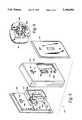
- FIG. 4is an exploded assembly view of the master switch shown in FIG. 2;
- FIG. 5is an exploded assembly view of the slave switch shown in FIG. 3;
- FIG. 6is an exploded isometric view of the system disconnect switch and the toggle switch included in the master switch unit shown in FIG. 2;
- FIG. 7is a cross-sectional view of a slave switch or a master switch with the switch in a first stable resting position
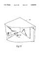
- FIG. 8is a cross-sectional view of the switch shown in FIG. 7 during activation of the switch from a first stable resting position to a second stable resting position;
- FIG. 9is a cross-sectional view of the switch shown in FIG. 7 with the switch in a second stable resting position
- FIG. 10is an exploded cross-sectional view of the switch contacts for the switch shown in FIG. 8;
- FIG. 11is an exploded plan view of the switch contacts shown in FIG. 10 with various components removed for clarity;
- FIG. 12is a block diagram of the electrical circuitry of the slave switch unit shown in FIG. 3;
- FIG. 13is a block diagram of the signal detection circuit in the master switch
- FIG. 14is a block diagram of the switching circuit in the master switch
- FIG. 15is a representative pictorial view of a first alternate embodiment for the switching system of the present invention.
- FIG. 16is a representative pictorial view of a second alternate embodiment for the switching system of the present invention.
- the wireless multiple position switchconsists of two components, a master switch and a slave switch.
- the master switch and the slave switcheach contain a switching mechanism which is designed to have the appearance and operational feel of a conventional household 120-VAC wall-mounted light switch.
- the mechanism of the present inventioncarries low-voltage DC, which is used to trigger a 120-VAC electronic switch located in the master switch and having no mechanical contacts.
- the switching mechanismhas the electrical characteristics of a conventional momentary-contact toggle switch. The contacts are normally open, but when the mechanism is activated, the contacts are closed for a brief interval of time.
- the toggle switchis activated by moving a toggle lever from a first stable resting position to a second stable resting position, or vice versa.
- Plastic partsmay be used to fabricate the switching mechanism, with the exception of the contacts and the ball bearing.
- the contacts and the ball bearingshould be fabricated from electrically conductive material.
- the master switchcontains a receiver and is designed to be used in place of a standard, two-way, two- or three-wire home light switch. Accordingly, the master switch operates on standard 120-VAC power.
- the slave switchcontains a transmitter, has the appearance of a home light switch, but requires no wiring.
- the slave (transmitter)communicates to the master (receiver) the information required to cause the master (receiver) switch to alternate its state.
- the master switchis wired in series between a power source and a load device. Reception frequencies are selected to match the transmitting frequencies of the slave switches.
- the systemis designed so that any number of slave (transmitter) units can be installed, each with the capacity to independently trigger a master switch.
- the function of the systemis to emulate the operation of a conventional three-way (or multiple-way) switching system without having to run wires between the master and slave switches.
- This systemmay be adapted to employ a plurality of transmitter/receiver systems. However, if more than one wireless multiple position switching system is used in a given dwelling, switches with different frequency ratings must be used. Otherwise, the switching systems will interact with one another such that the load controlled by a first wireless switching system might be intermittently triggered by other switching systems in use. Each wireless multiple position switch should be labelled with a channel number corresponding to a given frequency. This may be accomplished by means of stickers positioned on the packaging to enable the user to select systems which will not interact with one another. The system includes circuitry to guard against false actuations.
- the master switchcontains a system disconnect switch which allows the system to be switched off for an indefinite period of time.
- Non-metallic wall platesmust be used with the master and slave units, because metal wall plates will interfere with electromagnetic wave propagation, significantly reducing the operational range of the system in some cases.
- the unitis certified under FCC Part 15 and Underwriter's Laboratories. 500 watt switching capacity is provided. The minimum lighting load is 25 watts, incandescent only, and the maximum lighting load is 500 watts, incandescent only. The typical range is up to 50 feet, and the physical dimensions permit mounting in a standard electrical junction box.
- the slave switchprovides a battery life of about one year with a standard 9-volt cell.
- the wireless multiple position switchis ideal for household use, for example, in family rooms, dens, dining rooms, hallways, bedrooms, basements, utility rooms, and other places where convenient light control is desired. However, the system will not work with fluorescent lights, lights with fans, or other appliances.
- FIG. 1is a representative pictorial view of a typical installation for the multiple position wireless switching system 100 of the present invention.
- a power source 102provides standard 117-volt alternating current for the switching system 100.
- a master switch 104is connected in series with the power source 102 and a load device 106.
- Load device 106may be a light fixture hardwired to a pre-existing electrical system. Alternatively, the load device may be connected to the switching system by means of a standard switch wall outlet 108.
- a slave switch 110is placed at a desired remote switching location. However, to ensure reliable switching system performance, the master switch and the slave switch 104, 110 should not be physically separated by more than about 50 feet. Large metal objects situated between the master switch 104 and the slave switch 110 may interfere with the proper functioning of switching system 100.
- the slave switch 110contains a transmitter which generates a switching signal comprised of electromagnetic radiation. The switching signal is generated whenever the slave switch 110 is activated.
- the master switch 104may be activated in one of two ways. First, the switch may be a triggered response to the receipt of a switching signal from the slave switch 110. Additionally, the master switch 104 may be manually activated by a system user as desired. Upon activation, the master switch 104 reverses the energization state of the load device 106.
- the switching signal transmitted by the slave switch 110 and received by the master switch 104consists of electromagnetic radiation.
- the switching signalmay be modulated, or, alternatively, an open carrier may be employed.
- Virtually any desired frequencymay be selected for the switching signal; operation over a broad range of frequencies is possible from the ultrasonic region of the spectrum through ultraviolet light.
- the preferred embodimentuses signals in the range of approximately 300 mHz. This frequency range is desirable because it is situated in a relatively quiet area of the spectrum between TV channels 13 and 14, thus rendering interference between the switching system 100 and other services highly unlikely.
- FIG. 2illustrates a detailed isometric view of the master switch shown in FIG. 1.
- the master switch 104is housed in an outer enclosure 201 of dimensions sufficiently small to permit mounting of the master switch 104 in a standard electrical junction box.
- the outer enclosure 201may consist of a back plate 203 and two side members 205, 207.
- the back plate 203Acontains spring elements 204, 206, 208 for securing two side members 205, 207.
- the back plate 203may be contoured to form a top plate 209 and a bottom plate for the outer enclosure 201.
- the back plate 203may be further contoured to provide a plurality of mounting tabs 213, 215 for mounting the outer enclosure 201 in a standard electrical junction box.
- the master switch 104includes a front plate 217, a system disconnect switch 219, and system disconnect switch linkage 221.
- the plate 217includes a plurality of holes 223, 225, permitting the mounting of a standard or decorative non-metallic cover plate.
- System disconnect switch 219allows the switching system operator to remove all power from the switching system.
- the master switch 104is activated by means of toggle switch 227.
- Toggle switch 227is designed to have the look and the feel of a standard two-way or three-way switch. However, unlike conventional three-way switches which have two sets of contacts, the toggle switch 227 contains one set of contacts which is normally open. When activated, the contacts are shorted out momentarily and then remain open until the toggle switch 227 is activated again.
- FIG. 3is a detailed isometric view of the slave switch 110.
- the slave switch 110may be affixed to a wall at a desired control location by means of screws, fasteners, tape or other adhesive means.
- the slave switch 110includes a front enclosure 301, a battery compartment 303, a toggle switch 227 and mounting means 305 for mounting a standard or decorative non-metallic cover plate to the front enclosure 301.
- FIG. 4is an exploded assembly view of the master switch 104 shown in FIG. 2.
- a non-metallic front cover 219covers the front of the master switch 104.
- Boss plate 251secures the system disconnect switch 219, the toggle switch 227, and the system disconnect switch linkage 221.
- Toggle switch 227includes a toggle lever 253, a compression spring 255, an electrically conductive ball bearing 257, and a pivot member 259.
- the toggle lever 253contains an aperture 261 which accommodates the pivot member 259.
- Pivot member 259is secured by a retainer plate 263.
- the retainer plate 263contains a plurality of projections 265 which each contain apertures 266 for accommodating a pivot member 259.
- the retainer plate 263is held in place by two side members 205, 207.
- the side members 205, 207contain a plurality of raised projections 267 which exert compressive forces on the retainer plate 263.
- the side members 205, 207are secured by back plate 203.
- Back plate 203contains spring elements 204, 206, 208, 210, which exert compressive forces on side member ramps 273, 275, 277, 279.
- FIG. 5is an exploded assembly view of the slave switch shown in FIG. 3.
- a non-metallic cover plate 501covers the front of slave switch 110.
- the cover plate 501fits over front enclosure 301.
- Front enclosure 301contains an aperture 503 for accommodating a toggle switch lever, and a battery compartment aperture 505.
- Cover plate holes 507, 509accommodate fasteners or screws used to mount cover plate 501.
- Mounting holes 511, 513mount the front enclosure 301 to a retainer plate 515.
- Retainer plate 515contains battery compartment walls 517, cover plate holes 519, 521, and retainer plate holes 523, 525.
- the retainer plate 515contains a plurality of projections 527 which each contain apertures 529 for accommodating a pivot member 259 (FIG. 4). Pivot member 259 passes through an aperture 261 on a toggle lever 253, securing the toggle 1ever 253 to the retainer plate 515 (FIG. 6).
- FIG. 6is an exploded view of the retainer plate 515 toggle lever 253 assembly shown in FIG. 5.
- a system disconnect switch 537 situated next to toggle lever 253permits the system to be powered down.
- Disconnect switch linkage 539allows the system operator to turn the system disconnect switch 537 on and off after the cover plate 501 has been installed.
- the disconnect switch linkage 539is designed to be cosmetically unobtrusive as this function is used infrequently during normal system operation.
- FIG. 7is an exploded cross-sectional view of a switching mechanism assembly 701 employed in the present invention.
- the switching mechanism assembly 701may be incorporated into the master switch 104 and/or the slave switch 110.
- a toggle lever 253contains an inner aperture 705.
- the inner aperture 705houses a compression spring 255.
- an optional screw or fastener 709may be used to secure the compression spring 255 in the inner aperture 705.
- Compression spring 255applies force to a ball bearing 257G.
- Ball bearing 257should have an electrically conductive surface for the switching mechanism assembly 701 to operate as intended.
- FIG. 7shows the toggle lever 253 in one of two possible stable resting positions.
- the ball bearing 257rests in an aperture formed by a switch contact 713 and a lower raised projection 715. In the second resting position, the ball bearing would rest between switch contact 717 and an upper raised projection 719. However, in both resting positions, the contacts 713G, 717 are open and no current will flow from contact 713 to contact 717, or vice-versa.
- switching mechanism 701 componentsmay be fabricated from plastic, the operational characteristics of the mechanism are enhanced if the ball bearing 257 and the compression spring 255 are made of metal. Of course, the switch contacts 713 and 717, and the ball-bearing 257 must be fabricated of metal to permit the switching mechanism to function.
- FIG. 8displays the switching mechanism assembly 701 of FIG. 7 while the switch assembly 701 is being activated.
- the toggle lever 253is situated at an intermediate point between the two aforementioned stable resting positions.
- the compression spring 255Happlies force to the ball bearing 257, which, in turn, forces the ball bearing 257 against switch contacts 713, 717.
- the switch contacts 713, 717 and ball bearing 257complete an electrical circuit for a brief interval of time.
- switch assembly 701is a momentary-contact toggle switch.
- the switchis designed to look and feel similar to a conventional 117-VAC two- or multiple position household switch.
- FIG. 9illustrates the switching mechanism assembly 701 of FIG. 7 in the second resting position.
- the toggle lever 253Prior to activation, the toggle lever 253 is at the position indicated in FIG. 7. Upon activation, the lever 253 moves downward to reach the position shown in FIG. 8, and then travels further downward to the second resting position shown in FIG. 9 as 253. If the toggle lever 253, as shown in FIG. 9, is activated, the toggle lever 253 will travel upward to reach the position shown in FIG. 8, 253, before reaching the first equilibrium position shown in FIG. 7, 253.
- FIG. 10is an exploded cross-sectional view of the switch assembly shown in FIGS. 7-9 with the toggle lever 253 in the position shown at FIG. 8.
- FIG. 11is an exploded plan view of the switch contacts 713, 717 with the toggle lever 253, the compression spring 255, and the ball bearing 257 removed for clarity. To the left of switch contacts 713 and 717 is the system disconnect switch 537.
- FIG. 12is a block diagram of the electrical circuitry of the slave switch 110 shown in FIG. 1.
- Switch contacts 717, 713 FIG. 7 and switching mechanism assembly 227(FIG. 4) are configured as a single-pole, momentary-contact switch, shown at block 1201 (FIG. 12) as a switching signal activation means.
- An active filter 1203is used to broaden the response time of the switching signal activation means 1201. If the switching signal activation means 1201 was configured to key an RF oscillator 1207 directly, the RF oscillator 1207 would be activated for a very brief interval of time. Consequently, switching system operation would be extremely susceptible to electrical noise.
- the active filter 1203modifies the response time of the switching signal activation means 1201 to enable a gate 1205 whenever the switching signal activation means 1201 is activated.
- the gate 1205is enabled for approximately one second.
- poweris applied to the RF oscillator 1207 from a power supply 1209.
- the gate 1205may also be used to apply modulation to the RF oscillator 1207.
- the modulation signalmay be produced by a modulation oscillator 1211.
- the frequency of the modulation oscillatoris determined by a frequency reference 1213 which, for example, may be a crystal resonator operating in the range of approximately 30 kHz.
- each systemcan be configured to operate on a different modulation frequency by selecting appropriate crystal resonators for frequency reference 1213.
- the preferred embodimentoperates at one of three modulation frequencies: 28 kHz, 30 kHz or 32 kHz.
- RF oscillator 1207may be configured to operate in the frequency range of 300 mHz.
- the oscillatormay be modulated or unmodulated. For example, amplitude modulation, frequency modulation or open carrier could be employed.
- An output power of approximately 5 milliwatts into a 50- ⁇ loadis provided in the preferred embodiment.
- the maximum permissible output poweris determined by Part 15 of FCC Rules and Regulations, which sets limits on the electromagnetic field strength produced by RF-generating devices. With an output power of 5 mW and a short antenna 1221 comprised of several inches of wire, the slave switch 110 will operate in compliance with Part 15.
- the output of the oscillatoris coupled into the antenna 1221; band pass of low-pass filters may be used to purify the transmitted signal, but are not required for the present application.
- the antenna 1221may consist of a wire jumper or a printed-circuit trace running in close proximity to the tank circuit of the oscillator 1207.
- FIG. 13is a block diagram of a portion of the electrical circuitry of the master switch 104 illustrated in FIG. 1.
- An antenna 1301is used to receive the signal from the slave switch 110.
- the antenna 1301is a short length of wire several inches long.
- the signal from the antenna 1301is fed into an RF amplifier 1303 to increase the amplitude of the signal received by the antenna 1301.
- the signalis passed on to an RF detector 1305 which removes the RF carrier from the received signal.
- the resulting baseband signal at the output of the RF detector 1305is fed to a low frequency amplifier 1307 and a modulation filter 1309.
- the modulation filter 1309is designed to pass one or more discrete modulation frequencies. Any other frequencies which may be present are filtered out at this point.
- the modulation filter 1309is a crystal filter which is tuned to one of three frequencies - 28 kHz, 30 kHz or 32 kHz, depending upon the desired channel of operation.
- the output of the modulation filter 1309consisting of one or more discrete demodulated frequency components, is fed to a buffer amplifier 1311.
- the buffer amplifierincreases the amplitude of the demodulated signal so that the detected signal is of sufficient strength to drive a modulation detector 1313.
- Modulation detector 1313converts the discrete frequency components at the output of buffer amplifier 1311 into a DC voltage offset.
- the AC component of the waveformis removed by modulation detector 1313.
- the DC voltage offsetmay be used to control logic circuitry, including TTL and/or CMOS devices.
- FIG. 14is a block diagram of a portion of the electrical circuitry of the master switch 104 illustrated in FIG. 1.
- Switch contacts 711, 713 and switching mechanism assembly 227(FIG. 7) are configured as a single-pole, momentary-contact switch, shown as switching signal activation means 1401 (FIG. 14).
- the output of the switching signal activation means 1401is fed into a first input terminal of an OR gate 1405.
- the second input terminal of OR gate 1405accepts the detected signal from the receiver (FIG. 13).
- the output of OR gate 1405is processed by a buffer amplifier 1407 and the resulting signal is applied to the trigger input of a flip-flop 1409.
- the output of flip-flop 1409is amplified by a driver circuit 1411 to provide sufficient current to drive high-powered semiconductor devices.
- the driver circuit 1411drives an electronic switch 1413 which may be comprised of a DIAC, a TRIAC and related components.
- the electronic switch 1413controls current flow between a power source 102 (nominally 120-VAC) and a load device 106, such as an incandescent lamp.
- the electronic switch 1413is always in one of two mutually-exclusive states, ON or OFF. Whenever the trigger input of the flip-flop 1409 is activated, the electronic switch will reverse states.
- FIG. 15is a pictorial representation of an alternate embodiment for the present invention.
- a wireless switching system 5100is shown, including a power source 5102, a standard electrical outlet 5108, a master plug-in module 5109, and a slave switch 5110.
- the power source 5102consists of 120-VAC, 50 or 60 Hz alternating current.
- Power source 5102is connected to the standard electrical outlet 5108.
- Power to the standard electrical outletmay optionally be switched on and off by means of one or more standard electrical two-way or three-way switches.
- the master plug-in module 5109functions in a manner similar to the master switch 104 shown in FIG. 1.
- Master plug-in module 5109contains a receiver and an electronic switch. The receiver senses the presence of switching signals generated by a transmitter in the slave switch 5110.
- the electronic switch in the master plug-in module 5109will reverse its state. If the electronic switch was initially in the “off” state, receipt of the switching signal will trigger the switch into the "on” state. Conversely, if the electronic switch was initially in the “on” state, the switching signal will place the switch into the "off” state.
- the plug-in module 5109contains a two-prong or three-prong plug which may be inserted into a standard electrical outlet 5108.
- the plug-in module 5109contains one or more electrical outlets 5113, which each accept the standard electrical two-prong or three-prong plugs present on typical load devices, such as lamps or small appliances.
- FIG. 16illustrates a further alternate embodiment of the present invention.
- the wireless switching system 6100includes a power source 6102, a standard light bulb socket 6107, a master screw-in module 6106, a load device 6109 and a slave switch 6110.
- the power source 6102consists of 120-VAC, 50 or 60 Hz alternating current.
- Power source 6102is connected to the standard light bulb socket 6107. Power to the standard light bulb socket may optionally be switched on and off by means of one or more standard electrical two-way or three-way switches.
- the master screw-in module 6109functions in a manner similar to that of master switch 104 shown in FIG. 1 or plug-in module 5109 shown in FIG. 15. Master screw-in module 6109 contains a receiver and an electronic switch.
- the receiversenses the presence of switching signals generated by a transmitter in the slave switch 6110.
- the electronic switch in the master screw-in module 6109will reverse its state. If the electronic switch was initially in the “off” state, receipt of the switching signal will cause the switch to enter the "on” state. Conversely, if the electronic switch was initially in the “on” state, the switching signal will place the switch into the "off” state.
- the switching systemprovides a relatively simple installation procedure, which is readily implemented by a typical homeowner or layman having no special skills.
- the only tool need to install the switching systemis a flat-bladed screwdriver.
- a wall switch location that controls an outlet to a lamp or overhead incandescent lightis selected.
- the total lighting loadmust not exceed 500 watts.
- the master switchmust be able to easily detect the signals from the slave switch in the room or hallway where the system is installed so that the system will operate properly. Large metal objects should not be situated between the two switches. Otherwise, the switching signals may be attenuated, substantially reducing the operational range of the system.
- Power to the light switch circuitshould be turned off before installing the master switch. This should be done at the circuit breaker or fuse box.
- the master switchreplaces a conventional two-way switch. The existing switch is removed and its wires are disconnected. The screws may be saved for installation of the master switch. Some local building codes may require the switching system to be installed by a qualified electrician.
- Either wire coming from the master switchmay be connected to either wire coming from the wall box.
- One of the wire connectors supplied with the switching systemmay be used to secure the wires.
- the remaining wire coming from the master switchis connected to the other wire coming from the wall box.
- the wire connectionsshould be checked to make sure they are secure and no bare wires are exposed.
- the two screws removed earliermay be used to mount the master switch to the wall box.
- the excess wiringshould be placed into the wall box at this time.
- the wiresmay require forming to fit inside the box.
- the switch platewill be mounted later.
- Power to the light switch circuitis turned on at the circuit breaker or fuse box.
- the master switch system disconnect switchlocated beside the toggle switch, is positioned to its ON (up) position. If the switching system has been connected to a switched electrical outlet as opposed to a hard-wired light fixture, a lamp may be connected to the switched outlet, the lamp's switch should be turned on.
- the battery clips coming from the slave switchare snapped over the terminals of a 9-volt battery and the battery is placed into its compartment.
- the slave switchis held at the desired mounting location and switched on.
- the lightshould turn on immediately. After one second has elapsed, the slave switch may be switched off, in which case the light should turn off. This procedure may be repeated several times to ensure that the system is functioning properly. At least one second should elapse before the slave switch is toggled, otherwise the switch will not work properly.
- the antenna on the master switchshould be removed from its track and positioned inside the wall so that it hangs down. This will increase the range of the master switch and allow it to turn on the light more readily.
- the slave switchmay be repositioned at the desired location to make sure it operates the light. If necessary, the receiving antenna may be repositioned until the light works properly.
- the slave switchmay be mounted at the desired location with screws or double-stick tape.
- the wall plate removed earliermay be mounted over the slave switch with screws.
- a wall platemay be mounted over the master switch with the screws removed earlier. This completes the installation.
Landscapes
- Engineering & Computer Science (AREA)
- Power Engineering (AREA)
- Computer Networks & Wireless Communication (AREA)
- Selective Calling Equipment (AREA)
Abstract
Description
Claims (7)
Priority Applications (2)
| Application Number | Priority Date | Filing Date | Title |
|---|---|---|---|
| US08/026,392US5340954A (en) | 1991-05-02 | 1993-03-04 | Wireless multiple position switching system |
| US08/603,388US5818128A (en) | 1991-05-02 | 1996-02-20 | Wireless multiple position switching system |
Applications Claiming Priority (2)
| Application Number | Priority Date | Filing Date | Title |
|---|---|---|---|
| US07/694,649US5239205A (en) | 1991-05-02 | 1991-05-02 | Wireless multiple position switching system |
| US08/026,392US5340954A (en) | 1991-05-02 | 1993-03-04 | Wireless multiple position switching system |
Related Parent Applications (1)
| Application Number | Title | Priority Date | Filing Date |
|---|---|---|---|
| US07/694,649DivisionUS5239205A (en) | 1991-05-02 | 1991-05-02 | Wireless multiple position switching system |
Related Child Applications (1)
| Application Number | Title | Priority Date | Filing Date |
|---|---|---|---|
| US24151394ADivision | 1991-05-02 | 1994-05-12 |
Publications (1)
| Publication Number | Publication Date |
|---|---|
| US5340954Atrue US5340954A (en) | 1994-08-23 |
Family
ID=24789722
Family Applications (3)
| Application Number | Title | Priority Date | Filing Date |
|---|---|---|---|
| US07/694,649Expired - LifetimeUS5239205A (en) | 1991-05-02 | 1991-05-02 | Wireless multiple position switching system |
| US08/026,392Expired - LifetimeUS5340954A (en) | 1991-05-02 | 1993-03-04 | Wireless multiple position switching system |
| US08/603,388Expired - Fee RelatedUS5818128A (en) | 1991-05-02 | 1996-02-20 | Wireless multiple position switching system |
Family Applications Before (1)
| Application Number | Title | Priority Date | Filing Date |
|---|---|---|---|
| US07/694,649Expired - LifetimeUS5239205A (en) | 1991-05-02 | 1991-05-02 | Wireless multiple position switching system |
Family Applications After (1)
| Application Number | Title | Priority Date | Filing Date |
|---|---|---|---|
| US08/603,388Expired - Fee RelatedUS5818128A (en) | 1991-05-02 | 1996-02-20 | Wireless multiple position switching system |
Country Status (1)
| Country | Link |
|---|---|
| US (3) | US5239205A (en) |
Cited By (73)
| Publication number | Priority date | Publication date | Assignee | Title |
|---|---|---|---|---|
| US5818128A (en)* | 1991-05-02 | 1998-10-06 | Heath Company | Wireless multiple position switching system |
| US5925128A (en)* | 1996-03-22 | 1999-07-20 | Leonard Bloom A Part Interest | Access control module for a personal computer |
| GB2336045A (en)* | 1998-03-31 | 1999-10-06 | Exodus Electronic Ltd | Remotely controllable electrical switching apparatus |
| US5986358A (en)* | 1998-07-15 | 1999-11-16 | Gen-Home Technology Co. Ltd. | Remotely controllable wall switch |
| US6650029B1 (en) | 1998-03-31 | 2003-11-18 | Exodus Electronic Limited | Remotely controllable electrical switching apparatus |
| US20050068186A1 (en)* | 2003-09-30 | 2005-03-31 | Wanie Andrew J. | Water softener monitoring device |
| USD503607S1 (en) | 2003-09-03 | 2005-04-05 | Vip Investments, Ltd. | Faceplate |
| USD505855S1 (en) | 2003-09-03 | 2005-06-07 | Vip Investments, Ltd. | Faceplate |
| US6930260B2 (en) | 2001-02-28 | 2005-08-16 | Vip Investments Ltd. | Switch matrix |
| NL1025613C2 (en)* | 2004-03-02 | 2005-09-05 | Pex Franciscus Antonius Maria | Can be installed in a wall socket, remote controlled switch. |
| USD509127S1 (en) | 2003-09-03 | 2005-09-06 | Vip Investments, Ltd. | Faceplate |
| US20050280598A1 (en)* | 2004-06-21 | 2005-12-22 | Lutron Electronics Co., Inc. | Compact radio frequency transmitting and receiving antenna and control device employing same |
| USD516411S1 (en) | 2003-09-03 | 2006-03-07 | Vip Investments, Ltd. | Faceplate |
| USD521849S1 (en) | 2003-09-03 | 2006-05-30 | Vip Investments, Ltd. | Faceplate |
| US20060273970A1 (en)* | 2005-06-06 | 2006-12-07 | Lutron Electronics Co., Inc. | Load control device having a compact antenna |
| FR2893442A1 (en)* | 2005-11-16 | 2007-05-18 | Abmi Soc Par Actions Simplifie | Electronic device for creating two-way electrical circuit, has push buttons mechanically or electrically activating respective receiver and transmitting modules, where button activates relay which controls wired connection |
| US20070273309A1 (en)* | 2006-05-23 | 2007-11-29 | Carmen Lawrence R | Radio-frequency controlled motorized roller shade |
| US7307542B1 (en) | 2003-09-03 | 2007-12-11 | Vantage Controls, Inc. | System and method for commissioning addressable lighting systems |
| US20080055073A1 (en)* | 2006-09-06 | 2008-03-06 | Lutron Electronics Co., Inc. | Method of discovering a remotely-located wireless control device |
| US20080068126A1 (en)* | 2006-09-06 | 2008-03-20 | Lutron Electronics Co., Inc. | Procedure for addressing remotely-located radio frequency components of a control system |
| US20080068204A1 (en)* | 2006-09-06 | 2008-03-20 | Lutron Electronics Co., Inc. | Method of restoring a remote wireless control device to a known state |
| US20080111491A1 (en)* | 2006-11-13 | 2008-05-15 | Spira Joel S | Radio-frequency lighting control system |
| US20080136663A1 (en)* | 2006-09-06 | 2008-06-12 | Lutron Electronics Co., Inc. | Method of establishing communication with wireless control devices |
| US7394451B1 (en) | 2003-09-03 | 2008-07-01 | Vantage Controls, Inc. | Backlit display with motion sensor |
| US20080258563A1 (en)* | 2007-04-23 | 2008-10-23 | Jonas Joel Hodges | Electrical Communication Switch, Outlet, Companion Device, and System |
| US20090206983A1 (en)* | 2008-02-19 | 2009-08-20 | Lutron Electronics Co., Inc. | Communication System for a Radio-Frequency Load Control System |
| US20090206769A1 (en)* | 2008-02-19 | 2009-08-20 | Lutron Electronics Co., Inc. | Smart Load Control Device Having a Rotary Actuator |
| US7640351B2 (en) | 2005-11-04 | 2009-12-29 | Intermatic Incorporated | Application updating in a home automation data transfer system |
| US20100039240A1 (en)* | 2008-08-15 | 2010-02-18 | Wayne-Dalton Corp. | Method for Wiring Devices in a Structure Using a Wireless Network |
| US20100070100A1 (en)* | 2008-09-15 | 2010-03-18 | Finlinson Jan F | Control architecture and system for wireless sensing |
| US7694005B2 (en) | 2005-11-04 | 2010-04-06 | Intermatic Incorporated | Remote device management in a home automation data transfer system |
| US7698448B2 (en) | 2005-11-04 | 2010-04-13 | Intermatic Incorporated | Proxy commands and devices for a home automation data transfer system |
| US7755506B1 (en) | 2003-09-03 | 2010-07-13 | Legrand Home Systems, Inc. | Automation and theater control system |
| US7778262B2 (en) | 2005-09-07 | 2010-08-17 | Vantage Controls, Inc. | Radio frequency multiple protocol bridge |
| US20100225167A1 (en)* | 2009-03-06 | 2010-09-09 | Briggs And Stratton Corporation | Power management system and method of operating the same |
| US7870232B2 (en) | 2005-11-04 | 2011-01-11 | Intermatic Incorporated | Messaging in a home automation data transfer system |
| US20110050451A1 (en)* | 2009-09-03 | 2011-03-03 | Lutron Electronics Co., Inc. | Method of selecting a transmission frequency of a one-way wireless remote control device |
| US8330038B1 (en)* | 2011-12-20 | 2012-12-11 | Wright Ronnie H | Radium power pack and system for generating power |
| US8471779B2 (en) | 2010-05-17 | 2013-06-25 | Lutron Electronics Co., Inc. | Wireless battery-powered remote control with label serving as antenna element |
| US8598978B2 (en) | 2010-09-02 | 2013-12-03 | Lutron Electronics Co., Inc. | Method of configuring a two-way wireless load control system having one-way wireless remote control devices |
| US9167669B2 (en) | 2013-03-14 | 2015-10-20 | Lutron Electronic Co., Inc. | State change devices for switched electrical receptacles |
| US20160124567A1 (en)* | 2013-05-24 | 2016-05-05 | Vimar S.P.A. | A control unit for controlling electrical apparatus |
| US9386666B2 (en) | 2011-06-30 | 2016-07-05 | Lutron Electronics Co., Inc. | Method of optically transmitting digital information from a smart phone to a control device |
| US9413171B2 (en) | 2012-12-21 | 2016-08-09 | Lutron Electronics Co., Inc. | Network access coordination of load control devices |
| USD772175S1 (en)* | 2014-12-23 | 2016-11-22 | Eaton Corporation | Switch apparatus |
| US9538619B2 (en) | 2012-10-26 | 2017-01-03 | Lutron Electronics Co., Inc. | Controllable light source |
| US9544977B2 (en) | 2011-06-30 | 2017-01-10 | Lutron Electronics Co., Inc. | Method of programming a load control device using a smart phone |
| USD779444S1 (en)* | 2015-07-30 | 2017-02-21 | Eaton Corporation | Switch apparatus |
| US9578720B2 (en) | 2014-05-30 | 2017-02-21 | Lutron Electronics Co., Inc. | Wireless control device |
| USD779443S1 (en)* | 2015-07-30 | 2017-02-21 | Eaton Corporation | Switch apparatus |
| USD780132S1 (en)* | 2015-07-30 | 2017-02-28 | Eaton Corporation | Switch apparatus |
| USD780701S1 (en)* | 2015-07-30 | 2017-03-07 | Eaton Corporation | Switch apparatus |
| USD780700S1 (en)* | 2015-07-30 | 2017-03-07 | Eaton Corporation | Switch apparatus |
| US9614553B2 (en) | 2000-05-24 | 2017-04-04 | Enocean Gmbh | Energy self-sufficient radiofrequency transmitter |
| US9633557B2 (en) | 2014-06-24 | 2017-04-25 | Lutron Electronics Co., Inc. | Battery-powered retrofit remote control device |
| US9652979B2 (en) | 2014-05-30 | 2017-05-16 | Lutron Electronics Co., Inc. | Wireless control device |
| US9679696B2 (en) | 2012-11-14 | 2017-06-13 | Lutron Electronics Co., Inc. | Wireless load control device |
| USRE46499E1 (en) | 2001-07-03 | 2017-08-01 | Face International Corporation | Self-powered switch initiation system |
| US9848479B2 (en) | 2013-12-26 | 2017-12-19 | Lutron Electronics Co., Inc. | Faceplate remote control device for use in a load control system |
| US10019047B2 (en) | 2012-12-21 | 2018-07-10 | Lutron Electronics Co., Inc. | Operational coordination of load control devices for control of electrical loads |
| US10041292B2 (en) | 2011-03-11 | 2018-08-07 | Lutron Electronics Co., Inc. | Low-power radio-frequency receiver |
| US10135629B2 (en) | 2013-03-15 | 2018-11-20 | Lutron Electronics Co., Inc. | Load control device user interface and database management using near field communication (NFC) |
| US10244086B2 (en) | 2012-12-21 | 2019-03-26 | Lutron Electronics Co., Inc. | Multiple network access load control devices |
| US10271407B2 (en) | 2011-06-30 | 2019-04-23 | Lutron Electronics Co., Inc. | Load control device having Internet connectivity |
| US10317923B2 (en) | 2013-12-26 | 2019-06-11 | Lutron Technology Company Llc | Load-sensing remote control device for use in a load control system |
| US10559433B2 (en) | 2015-12-01 | 2020-02-11 | Switchdown Llc | Switching apparatus for synchronized toggle positioning and related sensory feedback |
| US10587147B2 (en) | 2011-08-29 | 2020-03-10 | Lutron Technology Company Llc | Two-part load control system mountable to a single electrical wallbox |
| US10806010B2 (en) | 2013-12-26 | 2020-10-13 | Lutron Technology Company Llc | Control device for use with a three-way lamp socket |
| US11513764B2 (en) | 2017-12-27 | 2022-11-29 | Leviton Manufacturing Co., Inc. | Wireless enabled load control device with voice controller |
| US12002632B2 (en) | 2020-10-09 | 2024-06-04 | Leviton Manufacturing Co., Inc. | Anywhere wireless switch and/or dimmer |
| USD1047939S1 (en)* | 2023-01-03 | 2024-10-22 | Wenzhou Nova New Energy Co., Ltd. | Electric switch |
| US12244129B2 (en) | 2019-12-24 | 2025-03-04 | Leviton Manufacturing Co., Inc. | Smart wall-plate system |
| US12300449B2 (en) | 2012-10-26 | 2025-05-13 | Lutron Technology Company Llc | Battery-powered retrofit remote control device |
Families Citing this family (56)
| Publication number | Priority date | Publication date | Assignee | Title |
|---|---|---|---|---|
| US5598039A (en)* | 1993-03-15 | 1997-01-28 | Touchstone Patent Trust | Method and apparatus for sensing state of electric power flow through a master circuit and producing remote control of a slave circuit |
| US5477113A (en)* | 1994-09-30 | 1995-12-19 | Toroid Hong Kong Limited | Apparatus for applying a variable voltage to an electric load |
| US5659209A (en)* | 1994-12-05 | 1997-08-19 | Fairform Mfg. Co., Ltd. | Supply/load on/off switching assembly |
| US5977882A (en)* | 1995-08-22 | 1999-11-02 | Moore; Clayton K. | Infrared remote controlled in-line power switch |
| US5736965A (en)* | 1996-02-07 | 1998-04-07 | Lutron Electronics Co. Inc. | Compact radio frequency transmitting and receiving antenna and control device employing same |
| US5731664A (en)* | 1996-04-08 | 1998-03-24 | Posa; John G. | Electrical switched load relocation apparatus |
| FR2759805B1 (en)* | 1997-02-17 | 1999-04-23 | E M Sat Engineering Et Materie | DEVICE FOR MANUAL, REMOTE CONTROL OF ELECTRICAL APPLIANCES |
| US6421322B1 (en) | 1997-11-17 | 2002-07-16 | Adc Telecommunications, Inc. | System and method for electronically identifying connections of a cross-connect system |
| US6350148B1 (en)* | 1999-02-10 | 2002-02-26 | Avaya Technology Corp. | Method and device for detecting the presence of a patch cord connector in a telecommunications patch system |
| US6700225B1 (en)* | 1999-10-05 | 2004-03-02 | Thomas C. Barmore | Digital electronic switching systems |
| KR20020085620A (en)* | 2001-05-09 | 2002-11-16 | 배을섭 | Switch capable of being remote controlled |
| FR2848034B1 (en)* | 2002-11-29 | 2005-02-11 | Somfy Sas | METHOD AND DEVICE FOR SUPPLYING THE ELECTRONIC MODULE OF A CONTROL DEVICE |
| US7274117B1 (en) | 2003-09-05 | 2007-09-25 | The Watt Stopper, Inc. | Radio wall switch |
| US7440246B2 (en)* | 2004-10-15 | 2008-10-21 | Leviton Manufacturing Co., Inc. | Circuit interrupting apparatus with remote test and reset activation |
| US20090212967A1 (en)* | 2004-10-15 | 2009-08-27 | Leviton Manufacturing Company, Inc | Circuit Interrupting System with Remote Test And Reset Activation |
| US7467888B2 (en)* | 2004-12-31 | 2008-12-23 | Ole K. Nilssen | Quick change power supply |
| US8386661B2 (en)* | 2005-11-18 | 2013-02-26 | Leviton Manufacturing Co., Inc. | Communication network for controlling devices |
| US20070176788A1 (en)* | 2006-02-02 | 2007-08-02 | Zion Mor | Remote control system for controlling wall-mounted switches |
| EP2006362A4 (en)* | 2006-03-30 | 2010-11-10 | Mitsui Shipbuilding Eng | Process for producing gas hydrate pellet |
| US7756556B2 (en)* | 2006-11-14 | 2010-07-13 | Leviton Manufacturing Company, Inc. | RF antenna integrated into a control device installed into a wall switch box |
| US7538285B2 (en)* | 2007-03-30 | 2009-05-26 | Leviton Manufacturing Company, Inc. | Electrical control device |
| TW200826396A (en)* | 2006-12-13 | 2008-06-16 | Inst Information Industry | Control circuit with manual/remote control function |
| US20090184652A1 (en)* | 2007-04-23 | 2009-07-23 | Lutron Electronics Co., Inc. | Antenna for a Load Control Device Having a Modular Assembly |
| KR101572819B1 (en)* | 2007-05-03 | 2015-12-01 | 코닌클리케 필립스 엔.브이. | A system for controlling light sources |
| DE102007026169A1 (en)* | 2007-06-04 | 2008-12-11 | Moeller Gmbh | Device and method for detecting the type of control for a voltage or current-triggering switching device |
| US20100101924A1 (en)* | 2007-07-18 | 2010-04-29 | Leviton Manufacturing Co., Inc. | Switching device |
| US20090028372A1 (en)* | 2007-07-23 | 2009-01-29 | Leviton Manufacturing Co., Inc. | Light fixture with sound capability |
| DE202007015713U1 (en)* | 2007-11-12 | 2008-02-07 | Osram Gesellschaft mit beschränkter Haftung | Control of lighting devices |
| US8468165B2 (en)* | 2007-12-02 | 2013-06-18 | Leviton Manufacturing Company, Inc. | Method for discovering network of home or building control devices |
| US8330638B2 (en) | 2008-04-04 | 2012-12-11 | Lutron Electronics Co., Inc. | Wireless battery-powered remote control having multiple mounting means |
| US8364325B2 (en) | 2008-06-02 | 2013-01-29 | Adura Technologies, Inc. | Intelligence in distributed lighting control devices |
| US8275471B2 (en) | 2009-11-06 | 2012-09-25 | Adura Technologies, Inc. | Sensor interface for wireless control |
| US7839017B2 (en)* | 2009-03-02 | 2010-11-23 | Adura Technologies, Inc. | Systems and methods for remotely controlling an electrical load |
| US8497634B2 (en)* | 2008-10-23 | 2013-07-30 | Innovation Works, Inc. | Wireless lighting system for staircases and passageways |
| US7714790B1 (en) | 2009-10-27 | 2010-05-11 | Crestron Electronics, Inc. | Wall-mounted electrical device with modular antenna bezel frame |
| US9155172B2 (en) | 2011-05-13 | 2015-10-06 | Lutron Electronics Co., Inc. | Load control device having an electrically isolated antenna |
| US9192019B2 (en) | 2011-12-07 | 2015-11-17 | Abl Ip Holding Llc | System for and method of commissioning lighting devices |
| US8975545B2 (en)* | 2012-05-22 | 2015-03-10 | Eaton Corporation | Circuit interrupter including indicator circuit |
| US10027127B2 (en) | 2013-03-14 | 2018-07-17 | Lutron Electronics Co., Inc. | Commissioning load control systems |
| US9590453B2 (en) | 2013-06-11 | 2017-03-07 | Lutron Electronics Co., Inc. | Configuring communications for a load control system |
| WO2015023768A1 (en) | 2013-08-14 | 2015-02-19 | Adc Telecommunications, Inc. | Inferring physical layer connection status of generic cables from planned single-end connection events |
| US10149369B2 (en) | 2013-11-21 | 2018-12-04 | Lutron Electronics Co., Inc. | Method of associating wireless control devices |
| US10339795B2 (en) | 2013-12-24 | 2019-07-02 | Lutron Technology Company Llc | Wireless communication diagnostics |
| US9699870B2 (en) | 2013-12-27 | 2017-07-04 | Lutron Electronics Co., Inc. | Wall-mountable wireless remote control device |
| US9851735B2 (en) | 2014-01-02 | 2017-12-26 | Lutron Electronics Co., Inc. | Wireless load control system |
| US9589461B1 (en)* | 2014-03-29 | 2017-03-07 | Hkc-Us, Llc | Battery powered wall mounted remote control for ceiling fans and lights |
| GB2527134A (en)* | 2014-06-14 | 2015-12-16 | Alexander Joseph Dawood | A light switch interface for electronic devices fitted into a light fitting |
| US10194512B2 (en) | 2014-06-27 | 2019-01-29 | Belkin International Inc. | Network light switch with mechanical/electrical interface port |
| WO2015200689A1 (en) | 2014-06-27 | 2015-12-30 | Belkin International, Inc. | Light switch controlling light source via wireless transmission |
| US10912179B2 (en) | 2014-06-27 | 2021-02-02 | Belkin International, Inc. | Systems and methods for contextual intelligence using networked devices |
| US9356472B2 (en) | 2014-09-02 | 2016-05-31 | e5 Global Innovations, Inc. | Systems and methods for remotely controlling a wall socket |
| US10957498B2 (en)* | 2016-07-07 | 2021-03-23 | Racepoint Energy, LLC | Intelligent lighting control system deployment with scalable wallplate |
| JP7002526B2 (en) | 2016-07-07 | 2022-01-20 | サバント システムズ インコーポレイテッド | Air gap devices, systems and methods for intelligent lighting control systems |
| US10066820B2 (en)* | 2016-07-12 | 2018-09-04 | Abl Ip Holding Llc | Wall mounted battery-powered wireless device |
| US11367583B2 (en)* | 2020-02-18 | 2022-06-21 | Canon Kabushiki Kaisha | Seesaw type operation unit used for zooming operation in video camera and electronic device |
| USD963595S1 (en)* | 2022-02-21 | 2022-09-13 | Guodong Cai | Switch |
Citations (4)
| Publication number | Priority date | Publication date | Assignee | Title |
|---|---|---|---|---|
| US4031345A (en)* | 1974-12-18 | 1977-06-21 | Grayhill, Inc. | Miniature electrical switch |
| US4439649A (en)* | 1982-08-30 | 1984-03-27 | Suncom, Incorporated | Joy stick switch |
| US5095181A (en)* | 1987-10-28 | 1992-03-10 | Mcgill Manufacturing Company, Inc. | Three-position safety rocker |
| US5158172A (en)* | 1991-01-28 | 1992-10-27 | Otto Engineering, Inc. | Toggle switch |
Family Cites Families (7)
| Publication number | Priority date | Publication date | Assignee | Title |
|---|---|---|---|---|
| JPS57147895A (en)* | 1981-03-10 | 1982-09-11 | Hitachi Ltd | Garage door controller |
| US4668876A (en)* | 1984-06-28 | 1987-05-26 | Skarman John S | Touch control switch and lamp system |
| US4889999A (en)* | 1988-09-26 | 1989-12-26 | Lutron Electronics Co., Inc. | Master electrical load control system |
| US5237207A (en)* | 1988-09-26 | 1993-08-17 | Lutron Electronics Co., Inc. | Master electrical load control system |
| US5170068A (en)* | 1988-09-26 | 1992-12-08 | Lutron Electronics Co., Inc. | Master electrical load control system |
| US5066898A (en)* | 1990-05-03 | 1991-11-19 | Delat Systems, Incorporated | Multi-way switch system having plural remote touch pads |
| US5239205A (en)* | 1991-05-02 | 1993-08-24 | Heath Company | Wireless multiple position switching system |
- 1991
- 1991-05-02USUS07/694,649patent/US5239205A/ennot_activeExpired - Lifetime
- 1993
- 1993-03-04USUS08/026,392patent/US5340954A/ennot_activeExpired - Lifetime
- 1996
- 1996-02-20USUS08/603,388patent/US5818128A/ennot_activeExpired - Fee Related
Patent Citations (4)
| Publication number | Priority date | Publication date | Assignee | Title |
|---|---|---|---|---|
| US4031345A (en)* | 1974-12-18 | 1977-06-21 | Grayhill, Inc. | Miniature electrical switch |
| US4439649A (en)* | 1982-08-30 | 1984-03-27 | Suncom, Incorporated | Joy stick switch |
| US5095181A (en)* | 1987-10-28 | 1992-03-10 | Mcgill Manufacturing Company, Inc. | Three-position safety rocker |
| US5158172A (en)* | 1991-01-28 | 1992-10-27 | Otto Engineering, Inc. | Toggle switch |
Cited By (185)
| Publication number | Priority date | Publication date | Assignee | Title |
|---|---|---|---|---|
| US5818128A (en)* | 1991-05-02 | 1998-10-06 | Heath Company | Wireless multiple position switching system |
| US5925128A (en)* | 1996-03-22 | 1999-07-20 | Leonard Bloom A Part Interest | Access control module for a personal computer |
| EP0948114A3 (en)* | 1998-03-31 | 2005-11-30 | Fitzgerald Lighting Ltd | Electrical switching apparatus |
| GB2336045A (en)* | 1998-03-31 | 1999-10-06 | Exodus Electronic Ltd | Remotely controllable electrical switching apparatus |
| GB2336045B (en)* | 1998-03-31 | 2002-11-27 | Exodus Electronic Ltd | Electrical switching apparatus |
| US6650029B1 (en) | 1998-03-31 | 2003-11-18 | Exodus Electronic Limited | Remotely controllable electrical switching apparatus |
| US5986358A (en)* | 1998-07-15 | 1999-11-16 | Gen-Home Technology Co. Ltd. | Remotely controllable wall switch |
| US9614553B2 (en) | 2000-05-24 | 2017-04-04 | Enocean Gmbh | Energy self-sufficient radiofrequency transmitter |
| US9887711B2 (en) | 2000-05-24 | 2018-02-06 | Enocean Gmbh | Energy self-sufficient radiofrequency transmitter |
| US7414210B2 (en) | 2001-02-28 | 2008-08-19 | Vantage Controls, Inc. | Button assembly with status indicator and programmable backlighting |
| US7432463B2 (en) | 2001-02-28 | 2008-10-07 | Vantage Controls, Inc. | Button assembly with status indicator and programmable backlighting |
| US7361853B2 (en) | 2001-02-28 | 2008-04-22 | Vantage Controls, Inc. | Button assembly with status indicator and programmable backlighting |
| US7432460B2 (en) | 2001-02-28 | 2008-10-07 | Vantage Controls, Inc. | Button assembly with status indicator and programmable backlighting |
| US6930260B2 (en) | 2001-02-28 | 2005-08-16 | Vip Investments Ltd. | Switch matrix |
| USRE46499E1 (en) | 2001-07-03 | 2017-08-01 | Face International Corporation | Self-powered switch initiation system |
| USD516411S1 (en) | 2003-09-03 | 2006-03-07 | Vip Investments, Ltd. | Faceplate |
| US7394451B1 (en) | 2003-09-03 | 2008-07-01 | Vantage Controls, Inc. | Backlit display with motion sensor |
| USD521849S1 (en) | 2003-09-03 | 2006-05-30 | Vip Investments, Ltd. | Faceplate |
| US7307542B1 (en) | 2003-09-03 | 2007-12-11 | Vantage Controls, Inc. | System and method for commissioning addressable lighting systems |
| USD505855S1 (en) | 2003-09-03 | 2005-06-07 | Vip Investments, Ltd. | Faceplate |
| USD503607S1 (en) | 2003-09-03 | 2005-04-05 | Vip Investments, Ltd. | Faceplate |
| USD509127S1 (en) | 2003-09-03 | 2005-09-06 | Vip Investments, Ltd. | Faceplate |
| USD548049S1 (en) | 2003-09-03 | 2007-08-07 | Vip Investments, Ltd. | Faceplate |
| US7755506B1 (en) | 2003-09-03 | 2010-07-13 | Legrand Home Systems, Inc. | Automation and theater control system |
| US7030768B2 (en) | 2003-09-30 | 2006-04-18 | Wanie Andrew J | Water softener monitoring device |
| USRE42386E1 (en) | 2003-09-30 | 2011-05-24 | Wanie Andrew J | Water softener monitoring system |
| US20060176185A1 (en)* | 2003-09-30 | 2006-08-10 | Wanic Andrew J | Water softener monitoring system |
| US7369055B2 (en) | 2003-09-30 | 2008-05-06 | Wanie Andrew J | Water softener monitoring system |
| US20050068186A1 (en)* | 2003-09-30 | 2005-03-31 | Wanie Andrew J. | Water softener monitoring device |
| US20070278964A1 (en)* | 2004-03-02 | 2007-12-06 | Franciscus Antonius Maria Pex | Remotely Controllable Switch For Incorporating In A Wall Socket |
| US7888823B2 (en) | 2004-03-02 | 2011-02-15 | Icom Technology B.V. | Remotely controllable switch for incorporating in a wall socket |
| WO2005089029A1 (en)* | 2004-03-02 | 2005-09-22 | Pex, Franciscus, Antonius, Maria | Remotely controllable switch for incorporating in a wall socket |
| NL1025613C2 (en)* | 2004-03-02 | 2005-09-05 | Pex Franciscus Antonius Maria | Can be installed in a wall socket, remote controlled switch. |
| US20070085755A1 (en)* | 2004-06-21 | 2007-04-19 | Lutron Electronics Co., Inc. | Compact radio frequency transmitting and receiving antenna and control device employing same |
| US20050280598A1 (en)* | 2004-06-21 | 2005-12-22 | Lutron Electronics Co., Inc. | Compact radio frequency transmitting and receiving antenna and control device employing same |
| US7362285B2 (en) | 2004-06-21 | 2008-04-22 | Lutron Electronics Co., Ltd. | Compact radio frequency transmitting and receiving antenna and control device employing same |
| US7408525B2 (en) | 2004-06-21 | 2008-08-05 | Lutron Electronics, Inc. | Compact radio frequency transmitting and receiving antenna and control device employing same |
| US20080042907A1 (en)* | 2004-06-21 | 2008-02-21 | Lutron Electronics Co., Inc. | Compact radio frequency transmitting and receiving antenna and control device employing same |
| US20080042914A1 (en)* | 2004-06-21 | 2008-02-21 | Lutron Electronics Co., Inc. | Compact radio frequency transmitting and receiving antenna and control device employing same |
| US7548216B2 (en) | 2004-06-21 | 2009-06-16 | Lutron Electronics Co., Inc. | Compact radio frequency transmitting and receiving antenna and control device employing same |
| US7573436B2 (en) | 2004-06-21 | 2009-08-11 | Lutron Electronics Co., Inc. | Compact radio frequency transmitting and receiving antenna and control device employing same |
| US7834817B2 (en) | 2005-06-06 | 2010-11-16 | Lutron Electronics Co., Inc. | Load control device having a compact antenna |
| US20060273970A1 (en)* | 2005-06-06 | 2006-12-07 | Lutron Electronics Co., Inc. | Load control device having a compact antenna |
| US20080303451A1 (en)* | 2005-06-06 | 2008-12-11 | Lutron Electronics Co., Inc. | Radio-frequency dimmer having a slider control |
| US7592967B2 (en) | 2005-06-06 | 2009-09-22 | Lutron Electronics Co., Inc. | Compact antenna for a load control device |
| US7778262B2 (en) | 2005-09-07 | 2010-08-17 | Vantage Controls, Inc. | Radio frequency multiple protocol bridge |
| US7698448B2 (en) | 2005-11-04 | 2010-04-13 | Intermatic Incorporated | Proxy commands and devices for a home automation data transfer system |
| US7694005B2 (en) | 2005-11-04 | 2010-04-06 | Intermatic Incorporated | Remote device management in a home automation data transfer system |
| US7640351B2 (en) | 2005-11-04 | 2009-12-29 | Intermatic Incorporated | Application updating in a home automation data transfer system |
| US7870232B2 (en) | 2005-11-04 | 2011-01-11 | Intermatic Incorporated | Messaging in a home automation data transfer system |
| FR2893442A1 (en)* | 2005-11-16 | 2007-05-18 | Abmi Soc Par Actions Simplifie | Electronic device for creating two-way electrical circuit, has push buttons mechanically or electrically activating respective receiver and transmitting modules, where button activates relay which controls wired connection |
| US7723939B2 (en) | 2006-05-23 | 2010-05-25 | Lutron Electronics Co., Inc. | Radio-frequency controlled motorized roller shade |
| US20070273309A1 (en)* | 2006-05-23 | 2007-11-29 | Carmen Lawrence R | Radio-frequency controlled motorized roller shade |
| US7880639B2 (en) | 2006-09-06 | 2011-02-01 | Lutron Electronics Co., Inc. | Method of establishing communication with wireless control devices |
| US20080055073A1 (en)* | 2006-09-06 | 2008-03-06 | Lutron Electronics Co., Inc. | Method of discovering a remotely-located wireless control device |
| US7755505B2 (en) | 2006-09-06 | 2010-07-13 | Lutron Electronics Co., Inc. | Procedure for addressing remotely-located radio frequency components of a control system |
| US7768422B2 (en) | 2006-09-06 | 2010-08-03 | Carmen Jr Lawrence R | Method of restoring a remote wireless control device to a known state |
| US20080068126A1 (en)* | 2006-09-06 | 2008-03-20 | Lutron Electronics Co., Inc. | Procedure for addressing remotely-located radio frequency components of a control system |
| US20080068204A1 (en)* | 2006-09-06 | 2008-03-20 | Lutron Electronics Co., Inc. | Method of restoring a remote wireless control device to a known state |
| US20080136663A1 (en)* | 2006-09-06 | 2008-06-12 | Lutron Electronics Co., Inc. | Method of establishing communication with wireless control devices |
| US20080111491A1 (en)* | 2006-11-13 | 2008-05-15 | Spira Joel S | Radio-frequency lighting control system |
| US20150236454A1 (en)* | 2007-04-23 | 2015-08-20 | Jonas Joel Hodges | Electrical communication switch, outlet, companion device, and system |
| US10181685B2 (en)* | 2007-04-23 | 2019-01-15 | Jonas Joel Hodges | Electrical communication switch, outlet, companion device, and system |
| US9054465B2 (en)* | 2007-04-23 | 2015-06-09 | Jonas Joel Hodges | Electrical communication switch, outlet, companion device, and system |
| US11289859B2 (en) | 2007-04-23 | 2022-03-29 | Jonas Joel Hodges | Electrical communication switch, outlet, companion device, and system |
| US20080258563A1 (en)* | 2007-04-23 | 2008-10-23 | Jonas Joel Hodges | Electrical Communication Switch, Outlet, Companion Device, and System |
| US20090206983A1 (en)* | 2008-02-19 | 2009-08-20 | Lutron Electronics Co., Inc. | Communication System for a Radio-Frequency Load Control System |
| US8212486B2 (en) | 2008-02-19 | 2012-07-03 | Lutron Electronics Co., Inc. | Smart load control device having a rotary actuator |
| US20110187282A1 (en)* | 2008-02-19 | 2011-08-04 | Lutron Electronics Co., Inc. | Smart Load Control Device Having a Rotary Actuator |
| US8427061B2 (en) | 2008-02-19 | 2013-04-23 | Lutron Electronics Co., Inc. | Smart load control device having a rotary actuator |
| US7872423B2 (en) | 2008-02-19 | 2011-01-18 | Lutron Electronics Co., Inc. | Smart load control device having a rotary actuator |
| US8786196B2 (en) | 2008-02-19 | 2014-07-22 | Lutron Electronics Co., Inc. | Load control system having a rotary actuator |
| US20090206769A1 (en)* | 2008-02-19 | 2009-08-20 | Lutron Electronics Co., Inc. | Smart Load Control Device Having a Rotary Actuator |
| US8598993B2 (en)* | 2008-08-15 | 2013-12-03 | Homerun Holdings Corporation | Method for wiring devices in a structure using a wireless network |
| US20100039240A1 (en)* | 2008-08-15 | 2010-02-18 | Wayne-Dalton Corp. | Method for Wiring Devices in a Structure Using a Wireless Network |
| US20100070100A1 (en)* | 2008-09-15 | 2010-03-18 | Finlinson Jan F | Control architecture and system for wireless sensing |
| US8324755B2 (en) | 2009-03-06 | 2012-12-04 | Briggs And Stratton Corporation | Power management system and method of operating the same |
| US20100225167A1 (en)* | 2009-03-06 | 2010-09-09 | Briggs And Stratton Corporation | Power management system and method of operating the same |
| US20110050451A1 (en)* | 2009-09-03 | 2011-03-03 | Lutron Electronics Co., Inc. | Method of selecting a transmission frequency of a one-way wireless remote control device |
| US8471779B2 (en) | 2010-05-17 | 2013-06-25 | Lutron Electronics Co., Inc. | Wireless battery-powered remote control with label serving as antenna element |
| US8598978B2 (en) | 2010-09-02 | 2013-12-03 | Lutron Electronics Co., Inc. | Method of configuring a two-way wireless load control system having one-way wireless remote control devices |
| US12203325B2 (en) | 2011-03-11 | 2025-01-21 | Lutron Technology Company Llc | Low-power radio-frequency receiver |
| US11753866B2 (en) | 2011-03-11 | 2023-09-12 | Lutron Technology Company Llc | Low-power radio-frequency receiver |
| US11946316B2 (en) | 2011-03-11 | 2024-04-02 | Lutron Technology Company Llc | Low-power radio-frequency receiver |
| US10041292B2 (en) | 2011-03-11 | 2018-08-07 | Lutron Electronics Co., Inc. | Low-power radio-frequency receiver |
| US9386666B2 (en) | 2011-06-30 | 2016-07-05 | Lutron Electronics Co., Inc. | Method of optically transmitting digital information from a smart phone to a control device |
| US12089318B2 (en) | 2011-06-30 | 2024-09-10 | Lutron Technology Company Llc | Method of optically transmitting digital information from a smart phone to a control device |
| US9923633B2 (en) | 2011-06-30 | 2018-03-20 | Lutron Electronics Co., Inc. | Method of optically transmitting digital information from a smart phone to a control device |
| US10588204B2 (en) | 2011-06-30 | 2020-03-10 | Lutron Technology Company Llc | Load control device having internet connectivity |
| US10367582B2 (en) | 2011-06-30 | 2019-07-30 | Lutron Technology Company Llc | Method of optically transmitting digital information from a smart phone to a control device |
| US10693558B2 (en) | 2011-06-30 | 2020-06-23 | Lutron Technology Company Llc | Method of optically transmitting digital information from a smart phone to a control device |
| US11388570B2 (en) | 2011-06-30 | 2022-07-12 | Lutron Technology Company Llc | Method of programming a load control device |
| US11765809B2 (en) | 2011-06-30 | 2023-09-19 | Lutron Technology Company Llc | Load control device having internet connectivity |
| US12144082B2 (en) | 2011-06-30 | 2024-11-12 | Lutron Technology Company Llc | Load control device having internet connectivity |
| US12317162B2 (en) | 2011-06-30 | 2025-05-27 | Lutron Technology Company Llc | Method of programming a load control device |
| US10271407B2 (en) | 2011-06-30 | 2019-04-23 | Lutron Electronics Co., Inc. | Load control device having Internet connectivity |
| US12075321B2 (en) | 2011-06-30 | 2024-08-27 | Lutron Technology Company Llc | Method of programming a load control device |
| US10779381B2 (en) | 2011-06-30 | 2020-09-15 | Lutron Technology Company Llc | Method of programming a load control device |
| US11412603B2 (en) | 2011-06-30 | 2022-08-09 | Lutron Technology Company Llc | Method of optically transmitting digital information from a smart phone to a control device |
| US9544977B2 (en) | 2011-06-30 | 2017-01-10 | Lutron Electronics Co., Inc. | Method of programming a load control device using a smart phone |
| US11889604B2 (en) | 2011-08-29 | 2024-01-30 | Lutron Technology Company, LLC | Two-part load control system mountable to a single electrical wallbox |
| US10587147B2 (en) | 2011-08-29 | 2020-03-10 | Lutron Technology Company Llc | Two-part load control system mountable to a single electrical wallbox |
| US11229105B2 (en) | 2011-08-29 | 2022-01-18 | Lutron Technology Company Llc | Two-part load control system mountable to a single electrical wallbox |
| US8330038B1 (en)* | 2011-12-20 | 2012-12-11 | Wright Ronnie H | Radium power pack and system for generating power |
| US10418193B2 (en) | 2012-10-26 | 2019-09-17 | Lutron Tehnology Company LLC | Controllable light source |
| US10104750B2 (en) | 2012-10-26 | 2018-10-16 | Lutron Electronics Co., Inc. | Controllable light source |
| US11102874B2 (en) | 2012-10-26 | 2021-08-24 | Lutron Technology Company Llc | Controllable light source |
| US10849206B2 (en) | 2012-10-26 | 2020-11-24 | Lutron Technology Company Llc | Battery-powered retrofit remote control device |
| US11837418B2 (en) | 2012-10-26 | 2023-12-05 | Lutron Technology Company Llc | Battery-powered retrofit remote control device |
| US9538619B2 (en) | 2012-10-26 | 2017-01-03 | Lutron Electronics Co., Inc. | Controllable light source |
| US9565742B2 (en) | 2012-10-26 | 2017-02-07 | Lutron Electronics Co., Inc. | Battery-powered retrofit remote control device |
| US12300449B2 (en) | 2012-10-26 | 2025-05-13 | Lutron Technology Company Llc | Battery-powered retrofit remote control device |
| US11102875B2 (en) | 2012-10-26 | 2021-08-24 | Lutron Technology Company Llc | Battery-powered retrofit remote control device |
| US10147560B2 (en) | 2012-10-26 | 2018-12-04 | Lutron Electronics Co., Inc. | Battery-powered retrofit remote control device |
| US12191070B2 (en) | 2012-11-14 | 2025-01-07 | Lutron Technology Company Llc | Wireless load control device |
| US9679696B2 (en) | 2012-11-14 | 2017-06-13 | Lutron Electronics Co., Inc. | Wireless load control device |
| US11170932B2 (en) | 2012-11-14 | 2021-11-09 | Lutron Technology Company, LLC | Wireless load control device |
| US11817257B2 (en) | 2012-11-14 | 2023-11-14 | Lutron Technology Company Llc | Wireless load control device |
| US11574771B2 (en) | 2012-11-14 | 2023-02-07 | Lutron Technology Company Llc | Wireless load control device |
| US10707014B2 (en) | 2012-11-14 | 2020-07-07 | Lutron Technology Company Llc | Wireless load control device |
| US12052331B2 (en) | 2012-12-21 | 2024-07-30 | Lutron Technology Company Llc | Multiple network access load control devices |
| US10019047B2 (en) | 2012-12-21 | 2018-07-10 | Lutron Electronics Co., Inc. | Operational coordination of load control devices for control of electrical loads |
| US12412467B2 (en) | 2012-12-21 | 2025-09-09 | Lutron Technology Company Llc | Network access coordination of load control devices |
| US11470187B2 (en) | 2012-12-21 | 2022-10-11 | Lutron Technology Company Llc | Multiple network access load control devices |
| US11301013B2 (en) | 2012-12-21 | 2022-04-12 | Lutron Technology Company, LLC | Operational coordination of load control devices for control of electrical loads |
| US12282367B2 (en) | 2012-12-21 | 2025-04-22 | Lutron Technology Company Llc | Operational coordination of load control devices for control of electrical loads |
| US9413171B2 (en) | 2012-12-21 | 2016-08-09 | Lutron Electronics Co., Inc. | Network access coordination of load control devices |
| US10244086B2 (en) | 2012-12-21 | 2019-03-26 | Lutron Electronics Co., Inc. | Multiple network access load control devices |
| US10050444B2 (en) | 2012-12-21 | 2018-08-14 | Lutron Electronics Co., Inc. | Network access coordination of load control devices |
| US10742032B2 (en) | 2012-12-21 | 2020-08-11 | Lutron Technology Company Llc | Network access coordination of load control devices |
| US11521482B2 (en) | 2012-12-21 | 2022-12-06 | Lutron Technology Company Llc | Network access coordination of load control devices |
| US12368791B2 (en) | 2012-12-21 | 2025-07-22 | Lutron Technology Company Llc | Multiple network access load control devices |
| US10694610B2 (en) | 2013-03-14 | 2020-06-23 | Lutron Technology Company Llc | Load control system for controlling electrical loads in response to state change information |
| US12317394B2 (en) | 2013-03-14 | 2025-05-27 | Lutron Technology Company Llc | State change devices for switched electrical receptacles |
| US9826604B2 (en) | 2013-03-14 | 2017-11-21 | Lutron Electronics Co., Inc. | State change devices for switched electrical receptacles |
| US9699871B2 (en) | 2013-03-14 | 2017-07-04 | Lutron Electronics Co., Inc. | State change devices for switched electrical receptacles |
| US10143071B2 (en) | 2013-03-14 | 2018-11-27 | Lutron Electronics Co., Inc. | Load control system for controlling electrical loads in response to state change information |
| US11083072B2 (en) | 2013-03-14 | 2021-08-03 | Lutron Technology Company Llc | Load control system for controlling electrical loads in response to state change information |
| US9167669B2 (en) | 2013-03-14 | 2015-10-20 | Lutron Electronic Co., Inc. | State change devices for switched electrical receptacles |
| US11240055B2 (en) | 2013-03-15 | 2022-02-01 | Lutron Technology Company Llc | Load control device user interface and database management using near field communication (NFC) |
| US10135629B2 (en) | 2013-03-15 | 2018-11-20 | Lutron Electronics Co., Inc. | Load control device user interface and database management using near field communication (NFC) |
| US10516546B2 (en) | 2013-03-15 | 2019-12-24 | Lutron Technology Company Llc | Load control device user interface and database management using Near Field Communication (NFC) |
| US20160124567A1 (en)* | 2013-05-24 | 2016-05-05 | Vimar S.P.A. | A control unit for controlling electrical apparatus |
| US10806010B2 (en) | 2013-12-26 | 2020-10-13 | Lutron Technology Company Llc | Control device for use with a three-way lamp socket |
| US11711876B2 (en) | 2013-12-26 | 2023-07-25 | Lutron Technology Company Llc | Faceplate remote control device for use in a load control system |
| US12317390B2 (en)* | 2013-12-26 | 2025-05-27 | Lutron Technology Company Llc | Faceplate remote control device for use in a load control system |
| US11229106B2 (en) | 2013-12-26 | 2022-01-18 | Lutron Technology Company Llc | Faceplate remote control device for use in a load control system |
| US10687409B2 (en) | 2013-12-26 | 2020-06-16 | Lutron Technology Company Llc | Faceplate remote control device for use in a load control system |
| US12174652B2 (en) | 2013-12-26 | 2024-12-24 | Lutron Technology Company Llc | Load-sensing remote control device for use in a load control system |
| US10317923B2 (en) | 2013-12-26 | 2019-06-11 | Lutron Technology Company Llc | Load-sensing remote control device for use in a load control system |
| US10314148B2 (en) | 2013-12-26 | 2019-06-04 | Lutron Technology Company Llc | Faceplate remote control device for use in a load control system |
| US20240032177A1 (en)* | 2013-12-26 | 2024-01-25 | Lutron Technology Company Llc | Faceplate Remote Control Device for Use in a Load Control System |
| US11825581B2 (en) | 2013-12-26 | 2023-11-21 | Lutron Technology Company Llc | Control device for use with a three-way lamp socket |
| US9848479B2 (en) | 2013-12-26 | 2017-12-19 | Lutron Electronics Co., Inc. | Faceplate remote control device for use in a load control system |
| US10068466B2 (en) | 2014-05-30 | 2018-09-04 | Lutron Electronics Co., Inc. | Wireless control device |
| US11915580B2 (en) | 2014-05-30 | 2024-02-27 | Lutron Technology Company Llc | Wireless control device |
| US9955548B2 (en) | 2014-05-30 | 2018-04-24 | Lutron Electronics Co., Inc. | Wireless control device |
| US9652979B2 (en) | 2014-05-30 | 2017-05-16 | Lutron Electronics Co., Inc. | Wireless control device |
| US9742580B2 (en) | 2014-05-30 | 2017-08-22 | Lutron Electronics Co., Inc. | Wireless control device |
| US9578720B2 (en) | 2014-05-30 | 2017-02-21 | Lutron Electronics Co., Inc. | Wireless control device |
| US10902718B2 (en) | 2014-05-30 | 2021-01-26 | Lutron Technology Company Llc | Wireless control device |
| US10149367B2 (en) | 2014-05-30 | 2018-12-04 | Lutron Electronics Co., Inc. | Wireless control device |
| US9609719B2 (en) | 2014-05-30 | 2017-03-28 | Lutron Electronics Co., Inc. | Wireless control device |
| US10147311B2 (en) | 2014-05-30 | 2018-12-04 | Lutron Electronics Co., Inc. | Wireless control device |
| US9699864B2 (en) | 2014-05-30 | 2017-07-04 | Lutron Electronics Co., Inc. | Wireless control device |
| US9633557B2 (en) | 2014-06-24 | 2017-04-25 | Lutron Electronics Co., Inc. | Battery-powered retrofit remote control device |
| US11043115B2 (en) | 2014-06-24 | 2021-06-22 | Lutron Technology Company Llc | Battery-powered retrofit remote control device |
| US12020561B2 (en) | 2014-06-24 | 2024-06-25 | Lutron Technology Company Llc | Battery-powered retrofit remote control device |
| US11657702B2 (en) | 2014-06-24 | 2023-05-23 | Lutron Technology Company Llc | Battery-powered retrofit remote control device |
| USD772175S1 (en)* | 2014-12-23 | 2016-11-22 | Eaton Corporation | Switch apparatus |
| USD795204S1 (en) | 2015-07-30 | 2017-08-22 | Eaton Corporation | Switch apparatus |
| USD779443S1 (en)* | 2015-07-30 | 2017-02-21 | Eaton Corporation | Switch apparatus |
| USD810032S1 (en) | 2015-07-30 | 2018-02-13 | Eaton Corporation | Switch apparatus |
| USD795205S1 (en) | 2015-07-30 | 2017-08-22 | Eaton Corporation | Switch apparatus |
| USD779444S1 (en)* | 2015-07-30 | 2017-02-21 | Eaton Corporation | Switch apparatus |
| USD798827S1 (en) | 2015-07-30 | 2017-10-03 | Eaton Corporation | Switch apparatus |
| USD780700S1 (en)* | 2015-07-30 | 2017-03-07 | Eaton Corporation | Switch apparatus |
| USD800078S1 (en) | 2015-07-30 | 2017-10-17 | Eaton Corporation | Switch apparatus |
| USD780701S1 (en)* | 2015-07-30 | 2017-03-07 | Eaton Corporation | Switch apparatus |
| USD780132S1 (en)* | 2015-07-30 | 2017-02-28 | Eaton Corporation | Switch apparatus |
| US10559433B2 (en) | 2015-12-01 | 2020-02-11 | Switchdown Llc | Switching apparatus for synchronized toggle positioning and related sensory feedback |
| US11513764B2 (en) | 2017-12-27 | 2022-11-29 | Leviton Manufacturing Co., Inc. | Wireless enabled load control device with voice controller |
| US12244129B2 (en) | 2019-12-24 | 2025-03-04 | Leviton Manufacturing Co., Inc. | Smart wall-plate system |
| US12002632B2 (en) | 2020-10-09 | 2024-06-04 | Leviton Manufacturing Co., Inc. | Anywhere wireless switch and/or dimmer |
| USD1047939S1 (en)* | 2023-01-03 | 2024-10-22 | Wenzhou Nova New Energy Co., Ltd. | Electric switch |
Also Published As
| Publication number | Publication date |
|---|---|
| US5239205A (en) | 1993-08-24 |
| US5818128A (en) | 1998-10-06 |
Similar Documents
| Publication | Publication Date | Title |
|---|---|---|
| US5340954A (en) | Wireless multiple position switching system | |
| JP3902660B2 (en) | Small radio frequency transmitting / receiving antenna and control device using the antenna | |
| US6687487B1 (en) | Repeater for transmission system for controlling and determining the status of electrical devices from remote locations | |
| US8289716B2 (en) | Dual load control device | |
| US5157273A (en) | Modular power outlet strip | |
| EP3696783B1 (en) | Wireless control device | |
| CN101842983B (en) | Method and apparatus for remotely operating an AC powered appliance from a video intercom or shopping terminal | |
| US5164609A (en) | Controllable power distribution system | |
| AU2012243250B2 (en) | Method and apparatus for combining AC power relay and current sensors with AC wiring devices | |
| US8237069B2 (en) | Control button having a single return spring for multiple buttons | |
| US20040130456A1 (en) | Intelligent switch assembly and system | |
| US7888823B2 (en) | Remotely controllable switch for incorporating in a wall socket | |
| EP3631586B1 (en) | Electrical control system, in particular for home automation systems | |
| US5036214A (en) | Remote control switch for controlling two electric supplies | |
| US20220334541A1 (en) | Electrical control apparatus, particularly for home automation systems | |
| US20030087678A1 (en) | Energy conservation system | |
| US11013088B2 (en) | Three-position operating mode switch | |
| JPH0746737A (en) | House wiring | |
| JP2004266923A (en) | Method for controlling table tap equipped with circuit breaker, and household electrical appliance | |
| HK1101243A (en) | Remotely controllable switch for incorporating in a wall socket | |
| HK1141902B (en) | Method and apparatus for remotely operating ac powered appliances from video interphones or shopping terminals |
Legal Events
| Date | Code | Title | Description |
|---|---|---|---|
| STCF | Information on status: patent grant | Free format text:PATENTED CASE | |
| AS | Assignment | Owner name:NATIONSBANK, N.A., NORTH CAROLINA Free format text:SECURITY AGREEMENT SUPPLEMENT;ASSIGNORS:HEATH HOLDING CORP.;HEATH COMPANY;REEL/FRAME:009123/0123 Effective date:19980204 | |
| FPAY | Fee payment | Year of fee payment:4 | |
| SULP | Surcharge for late payment | ||
| AS | Assignment | Owner name:HEATH HOLDING CORP., MICHIGAN Free format text:MERGER;ASSIGNOR:HEATH COMPANY;REEL/FRAME:009614/0666 Effective date:19980527 Owner name:DESA INTERNATIONAL, INC., KENTUCKY Free format text:ASSIGNMENT OF ASSIGNORS INTEREST;ASSIGNOR:HEATH HOLDING CORP.;REEL/FRAME:009614/0661 Effective date:19980527 | |
| FEPP | Fee payment procedure | Free format text:PAYOR NUMBER ASSIGNED (ORIGINAL EVENT CODE: ASPN); ENTITY STATUS OF PATENT OWNER: LARGE ENTITY | |
| AS | Assignment | Owner name:HEATH HOLDING CORP., MICHIGAN Free format text:"DOCUMENT PREVIOUSLY RECORDED AT REEL 9614 FRAME 0666 CONTAINED AN ERROR IN PROPERTY NUMBER 5818218. DOCUMENT RERECORDED TO CORRECT ERROR ON STATED REEL".;ASSIGNOR:HEATH COMPANY;REEL/FRAME:009950/0597 Effective date:19980527 | |
| AS | Assignment | Owner name:DESA INTERNATIONAL, INC., KENTUCKY Free format text:"DOCUMENT PREVIOUSLY RECORDED AT REEL 9614, FRAME 0661 CONTAINED ERROR IN PROPERTY NUMBER 5818218. DOCUMENT RERECORDED TO CORRECT ERROR ON STATED REEL".;ASSIGNOR:HEATH HOLDING CORP.;REEL/FRAME:009950/0326 Effective date:19980527 | |
| FPAY | Fee payment | Year of fee payment:8 | |
| AS | Assignment | Owner name:BANK OF AMERICA, N.A., NORTH CAROLINA Free format text:SECURITY INTEREST;ASSIGNORS:DESA INTERNATIONAL, INC.;DESA HOLDINGS CORPORATION;REEL/FRAME:013019/0552 Effective date:20020612 | |
| AS | Assignment | Owner name:ABLECO FINANCE LLC, AS COLLATERAL AGENT, NEW YORK Free format text:SECURITY INTEREST;ASSIGNOR:DESA IP, LLC;REEL/FRAME:013933/0061 Effective date:20021226 | |
| AS | Assignment | Owner name:DESA INTERNATIONAL LLC, KENTUCKY Free format text:CONVERSION FROM CORP. TO LLC;ASSIGNOR:DESA INTERNATIONAL, INC.;REEL/FRAME:013964/0276 Effective date:20030103 Owner name:DESA IP, LLC, FLORIDA Free format text:ASSIGNMENT OF ASSIGNORS INTEREST;ASSIGNOR:DESA INTERNATIONAL LLC;REEL/FRAME:013964/0866 Effective date:20021226 | |
| AS | Assignment | Owner name:DESA IP, LLC, FLORIDA Free format text:ASSIGNMENT OF ASSIGNORS INTEREST;ASSIGNOR:DESA INTERNATIONAL LLC;REEL/FRAME:014373/0884 Effective date:20021226 | |
| AS | Assignment | Owner name:HEATH HOLDING CORP., MICHIGAN Free format text:BANKRUPTCY COURT SALE ORDER CLEARING ALL LIENS, INCLUDING, BUT NOT LIMITED TO, THE SECURITY INTEREST RECORDED AT REEL/FRAME 009123/0123;ASSIGNOR:NATIONSBANK, N.A.;REEL/FRAME:015400/0205 Effective date:20021212 Owner name:HEATH COMPANY, MICHIGAN Free format text:BANKRUPTCY COURT SALE ORDER CLEARING ALL LIENS, INCLUDING, BUT NOT LIMITED TO, THE SECURITY INTEREST RECORDED AT REEL/FRAME 009123/0123;ASSIGNOR:NATIONSBANK, N.A.;REEL/FRAME:015400/0205 Effective date:20021212 Owner name:DESA INTERNATIONAL, INC., KENTUCKY Free format text:BANKRUPTCY COURT SALE ORDER RELEASING ALL LIENS, INCLUDING, BUT NOT LIMITED TO, THE SECURITY INTEREST RECORDED AT REEL/FRAME 013019/0552;ASSIGNOR:BANK OF AMERICA, N.A.;REEL/FRAME:015400/0264 Effective date:20021212 Owner name:DESA HOLDINGS CORPORATION, KENTUCKY Free format text:BANKRUPTCY COURT SALE ORDER RELEASING ALL LIENS, INCLUDING, BUT NOT LIMITED TO, THE SECURITY INTEREST RECORDED AT REEL/FRAME 013019/0552;ASSIGNOR:BANK OF AMERICA, N.A.;REEL/FRAME:015400/0264 Effective date:20021212 Owner name:DESA IP, LLC, KENTUCKY Free format text:BANKRUPTCY COURT SALE ORDER CLEARING ALL LIENS, INCLUDING, BUT NOT LIMITED TO, THE SECURITY INTEREST RECORDED AT REEL/FRAME 013933/0061;ASSIGNOR:ABLECO FINANCE LLC;REEL/FRAME:015400/0285 Effective date:20021212 | |
| AS | Assignment | Owner name:DESA IP, LLC, KENTUCKY Free format text:RELEASE OF SECURITY INTEREST;ASSIGNOR:ABLECO FINANCE LLC;REEL/FRAME:015442/0253 Effective date:20041206 | |
| AS | Assignment | Owner name:MERRILL LYNCH CAPITAL, A DIVISION OF MERRILL LYNCH Free format text:SECURITY AGREEMENT;ASSIGNOR:DESA IP, LLC;REEL/FRAME:015452/0092 Effective date:20041206 | |
| FPAY | Fee payment | Year of fee payment:12 | |
| AS | Assignment | Owner name:DESA IP, LLC, KENTUCKY Free format text:PARTIAL RELEASE OF SECURITY INTEREST;ASSIGNOR:MERRILL LYNCH CAPITAL, A DIVISION OF MERRILL LYNCH BUSINESS FINANCIAL SERVICES INC., AS ADMINISTRATIVE AGENT;REEL/FRAME:019825/0251 Effective date:20070830 Owner name:DESA IP, LLC,KENTUCKY Free format text:PARTIAL RELEASE OF SECURITY INTEREST;ASSIGNOR:MERRILL LYNCH CAPITAL, A DIVISION OF MERRILL LYNCH BUSINESS FINANCIAL SERVICES INC., AS ADMINISTRATIVE AGENT;REEL/FRAME:019825/0251 Effective date:20070830 | |
| AS | Assignment | Owner name:HEATHCO LLC, ILLINOIS Free format text:ASSIGNMENT OF ASSIGNORS INTEREST;ASSIGNOR:DESA IP, LLC;REEL/FRAME:020010/0766 Effective date:20070828 Owner name:HEATHCO LLC,ILLINOIS Free format text:ASSIGNMENT OF ASSIGNORS INTEREST;ASSIGNOR:DESA IP, LLC;REEL/FRAME:020010/0766 Effective date:20070828 |