US5340231A - Pavement marker - Google Patents
Pavement markerDownload PDFInfo
- Publication number
- US5340231A US5340231AUS07/809,645US80964591AUS5340231AUS 5340231 AUS5340231 AUS 5340231AUS 80964591 AUS80964591 AUS 80964591AUS 5340231 AUS5340231 AUS 5340231A
- Authority
- US
- United States
- Prior art keywords
- housing
- marker
- wall
- pavement
- lens
- Prior art date
- Legal status (The legal status is an assumption and is not a legal conclusion. Google has not performed a legal analysis and makes no representation as to the accuracy of the status listed.)
- Expired - Lifetime
Links
- 239000003550markerSubstances0.000titleclaimsabstractdescription88
- 239000000853adhesiveSubstances0.000claimsdescription39
- 230000001070adhesive effectEffects0.000claimsdescription39
- 239000000463materialSubstances0.000claimsdescription19
- 230000002093peripheral effectEffects0.000claimsdescription18
- 239000007787solidSubstances0.000claimsdescription8
- 239000012815thermoplastic materialSubstances0.000claimsdescription6
- 230000014759maintenance of locationEffects0.000claimsdescription5
- 229920001169thermoplasticPolymers0.000claimsdescription5
- 239000004416thermosoftening plasticSubstances0.000claimsdescription5
- 210000004027cellAnatomy0.000description29
- 239000004593EpoxySubstances0.000description21
- 239000011521glassSubstances0.000description11
- 239000010426asphaltSubstances0.000description10
- 230000008901benefitEffects0.000description8
- 230000036961partial effectEffects0.000description7
- 238000010276constructionMethods0.000description6
- 238000005299abrasionMethods0.000description5
- 238000009434installationMethods0.000description5
- 238000001465metallisationMethods0.000description5
- 238000004382pottingMethods0.000description5
- 229920002877acrylic styrene acrylonitrilePolymers0.000description4
- 238000000465mouldingMethods0.000description4
- 235000012773wafflesNutrition0.000description4
- 230000009471actionEffects0.000description3
- 210000002421cell wallAnatomy0.000description3
- 230000006835compressionEffects0.000description3
- 238000007906compressionMethods0.000description3
- 235000014510cookyNutrition0.000description3
- 230000032798delaminationEffects0.000description3
- 238000013461designMethods0.000description3
- 239000003365glass fiberSubstances0.000description3
- 238000011068loading methodMethods0.000description3
- 230000002829reductive effectEffects0.000description3
- 229920001431Long-fiber-reinforced thermoplasticPolymers0.000description2
- NIXOWILDQLNWCW-UHFFFAOYSA-Nacrylic acid groupChemical groupC(C=C)(=O)ONIXOWILDQLNWCW-UHFFFAOYSA-N0.000description2
- 230000000903blocking effectEffects0.000description2
- 239000011248coating agentSubstances0.000description2
- 238000000576coating methodMethods0.000description2
- 230000000295complement effectEffects0.000description2
- 239000002131composite materialSubstances0.000description2
- 238000005520cutting processMethods0.000description2
- 238000011161developmentMethods0.000description2
- 230000018109developmental processEffects0.000description2
- 230000007613environmental effectEffects0.000description2
- 210000004013groinAnatomy0.000description2
- 238000005304joiningMethods0.000description2
- 238000000034methodMethods0.000description2
- 238000012986modificationMethods0.000description2
- 230000004048modificationEffects0.000description2
- 229920000642polymerPolymers0.000description2
- 230000035939shockEffects0.000description2
- 238000003466weldingMethods0.000description2
- 230000001464adherent effectEffects0.000description1
- 230000003466anti-cipated effectEffects0.000description1
- 230000000712assemblyEffects0.000description1
- 238000000429assemblyMethods0.000description1
- 230000001413cellular effectEffects0.000description1
- 210000003850cellular structureAnatomy0.000description1
- 238000006243chemical reactionMethods0.000description1
- 150000001875compoundsChemical class0.000description1
- 239000013078crystalSubstances0.000description1
- 230000003292diminished effectEffects0.000description1
- 238000009826distributionMethods0.000description1
- 230000000694effectsEffects0.000description1
- 230000008030eliminationEffects0.000description1
- 238000003379elimination reactionMethods0.000description1
- 229920006332epoxy adhesivePolymers0.000description1
- 238000005429filling processMethods0.000description1
- 230000003116impacting effectEffects0.000description1
- 238000002347injectionMethods0.000description1
- 239000007924injectionSubstances0.000description1
- 238000012423maintenanceMethods0.000description1
- 239000002184metalSubstances0.000description1
- 238000005058metal castingMethods0.000description1
- 239000004033plasticSubstances0.000description1
- 229920003023plasticPolymers0.000description1
- 230000008569processEffects0.000description1
- 230000001902propagating effectEffects0.000description1
- 230000001681protective effectEffects0.000description1
- 238000002310reflectometryMethods0.000description1
- 230000000452restraining effectEffects0.000description1
- 230000002441reversible effectEffects0.000description1
- 239000004576sandSubstances0.000description1
- 239000000126substanceSubstances0.000description1
Images


Classifications
- E—FIXED CONSTRUCTIONS
- E01—CONSTRUCTION OF ROADS, RAILWAYS, OR BRIDGES
- E01F—ADDITIONAL WORK, SUCH AS EQUIPPING ROADS OR THE CONSTRUCTION OF PLATFORMS, HELICOPTER LANDING STAGES, SIGNS, SNOW FENCES, OR THE LIKE
- E01F9/00—Arrangement of road signs or traffic signals; Arrangements for enforcing caution
- E01F9/50—Road surface markings; Kerbs or road edgings, specially adapted for alerting road users
- E01F9/553—Low discrete bodies, e.g. marking blocks, studs or flexible vehicle-striking members
Definitions
- the present inventionrelates to pavement markers of the retroreflector type which are cleaned by the action of vehicle tires passing over the markers and, in particular, to markers having improved retroreflectors and housings.
- Pavement markershave become widely accepted as permanent installations for providing visible signals which mark traffic lanes and control the flow of traffic on roadways in combination with, or in place of, conventional painted traffic lines.
- a large number of such markersemploy retroreflectors which retroreflect light emanating from oncoming vehicles to provide a signal visible to the operators of such oncoming vehicles.
- Exemplary of other pavement markers previously knownare those disclosed in U.S. Pat. No. 3,790,293 issued to S. A. Heenan et al., on Feb. 5, 1974, and U.S. Pat. No. 3,809,487, issued to R. M. Flanagan on May 7, 1974, both commonly assigned herewith.
- the plastic retroreflector elementsare first formed as part of the walls of a hollow shell, and then a layer of metal, by vacuum metallization, is deposited on the exposed faces of the cube corner retroreflector elements. Following that step, the "shell" is filled or “potted” with a rigid epoxy-type material.
- the resulting structureis relatively rigid and over the years has proven to be remarkably durable in use.
- exposure of the metallization to moisturemay lead to failure of the retroreflector.
- because of the diminution in specific intensity of the reflected light(caused by the metallization of the retroreflector elements and distortion during the epoxy filling process, see, for example, Suhr et al U.S. Pat. No.
- full epoxy-filled markersprovide a textured and flat bottom surface, which makes them readily adherent through either bitumen or epoxy adhesive to any roadway surface.
- hollow ribbed type markerssuch as for example the type of temporary roadway marker illustrated in Luckinbill U.S. Pat. No. D-267,983
- hollow ribbed type markerstend to act as a "cookie cutter” against the bitumen.
- another advantage of the present inventionis the ability to employ, in a pavement marker having a thermoplastic hollow base member, means for achieving higher retroreflectivity, by eliminating the metallizing of and potting against reflective elements, while also providing a relatively flat bottom surface to enhance the bond between the installed marker and the underlying roadway surface.
- Another object of the present inventionis to provide a marker having a particular configuration for its base which will enable the marker to be inexpensively and efficiently produced while at the same time providing a new and novel combination of various elements so as to achieve the foregoing objectives.
- Yet another object of the present inventionis to provide an improved pavement marker which, through the use of certain selected materials, provides enhanced durability.
- the reflector housingis constructed of a long-fiber-reinforced thermoplastic material having properties which demonstrate superior performance in a variety of environmental conditions from high to low temperatures. The material so used provides improved impact and compression resistance of the reflector assembly, together with excellent abrasion and mar resistance.
- Still another object of the present inventionis to provide an improved reflector housing having hollow recesses formed by a ribbed structure and filled with epoxy to form a flat bottom surface that is textured for better adherence to a bituminous adhesive and which will have reduced delamination and brittleness failures.
- an improved retroreflective lens assembly and housing for pavement markersprimarily adapted for use in "sun country” areas.
- a pavement markeris disclosed for application directly to the road surface or into a groove cut into the road surface.
- the pavement markershave a shape designed for optimum strength and resistance to applied forces.
- the base or housing and the lens assembly configurationare designed to work especially well with more "flexible” pavement surfaces, thus allowing for flexure, but still maintaining adequate strength in elevated temperatures.
- the basewhen produced from acrylic-styrene-acrylonitrile (ASA), is highly weatherable, with good impact resistance and very good color stability. It may be colored to match the lens or other highway markings. Substantially radiused corners are used to minimize tire impact forces and reduce internal stresses.
- the base ribsare designed for optimum strength while preserving material and providing good flow in the mold. The underside edges along the perimeter of the base have ample radii to restrict cutting through bituminous-type installation adhesives.
- Teeth or recesses on the bottom of the front and rear edges of the baseprovide handling advantages and a means to help diffuse adhesive around the edges to avoid the adhesive riding up on the lens assembly.
- the lensis set deeply into a recess or pocket in the housing with part of the lens brow built into the housing. In this manner, the only way the lens may break out of the pocket in which it sets is straight out, thus providing resistance to flexural forces.
- the lens housingin which the retroreflector is positioned, is constructed of a long-glass-fiber-reinforced thermoplastic material such as Celstran N 50G from Polymer Composites, Inc. of Winona, Minn., providing improved impact and compression resistance of the pavement marker.
- a long-glass-fiber-reinforced thermoplastic materialsuch as Celstran N 50G from Polymer Composites, Inc. of Winona, Minn.
- Conventional thermoplasticsincluding those formed with short glass fibers, demonstrate poor impact resistance when formulated for high compressive strength and vice versa. Due to the long glass fibers, of about 1/2 inch, of these novel materials, both increased impact and compressive strength can be attained, making it ideal for the present application.
- a still further important featureis that the front face or lens portion of the retroreflective lens assembly is inclined at an angle which results in reduced abrasive action on the lens.
- this face angleis approximately 35° relative to the roadway surface.
- the lens assembly of the present markerswill incorporate an array of two cube-corner reflective elements surrounded by a wall to define a cell for strength and support.
- this arrangementprovides improved retroreflectivity and, accordingly, better visibility of the marker as compared with the use of a single cube-corner element in such a cell.
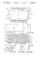
- FIG. 1is a perspective view of an improved partially epoxy-filled pavement marker
- FIG. 2is a top plan view of the marker shown in FIG. 1;
- FIG. 3is an enlarged top plan view of the marker shown in FIG. 2 without the retroreflective lens assembly in position;
- FIG. 4is a partial sectional elevational view taken along the line 4--4 in FIG. 3;
- FIG. 5is a bottom view of the marker housing in FIG. 3, without the epoxy fill;
- FIG. 6is a transverse sectional view in elevation taken along line 6--6 of FIG. 3;
- FIG. 7is an enlarged partial section view of one side of the device shown in FIG. 6;
- FIG. 8is a partial sectional elevational schematic view of the preferred form of the lens assembly mounted in the housing of the marker;
- FIG. 9is a side elevation view in cross section of a retroreflective lens assembly having two rows of cells
- FIG. 10is a side elevational view, in cross section, of a retroreflective lens having three rows of cells;
- FIGS. 11 and 12are a top and side view, respectively, of a lens backing for the retroreflective lenses of the type contemplated herein;
- FIG. 13is a cross-sectional partial elevation view of a metallized potted shell reflector that can be found in the prior art
- FIGS. 14-16are various views of an alternate version of the marker using a two-piece housing in lieu of the partial epoxy fill;
- FIGS. 17 and 18are views of the bottom plate for the construction shown in FIGS. 14-16;
- FIGS. 19 and 20are cross-sectional elevation views of alternate pavement markers
- FIG. 21is a view of one embodiment of the novel lens assembly of the present invention taken normal to the front face;
- FIG. 22is a partial end view of the lens assembly illustrated in FIG. 21;
- FIG. 23is a detailed view of the walls in the lens assembly that separate the columns of retroreflective elements in the cells.
- FIG. 24is a detailed view of the walls separating rows of the cells
- FIG. 25is a view similar to FIG. 8, in which yet a slightly further modified version of the pavement marker housing is illustrated.
- FIG. 26is a view similar to FIG. 25, with yet a further modified housing and lens arrangement.
- the pavement marker 150is adapted for use in a sun country where the possibility of impact by snowplow blades is remote at best and which marker can be effectively utilized when it is placed directly on the surface of the roadway (or in a groove in the roadway).
- the marker 150includes a housing 160 and a retroreflective lens assembly 180.
- the housing 160is constructed of a first thermoplastic material, such as ASA, and has a substantially hollow ribbed shell having rounded outer ends 186 joining a top wall 176.
- the housing 160is supported by spaced, integrally formed, depending rib means 172 (see FIGS. 4-6) extending longitudinally of the housing 160 that provide suitable strength while conserving material, providing ease in handling, and enabling good material flow during the molding operation.
- a pair of the depending ribs 172are spaced from a central longitudinal rib 172a and all are integrally interconnected along their longitudinal extent by the top wall 176 and spaced transversely disposed ribs 173 into a generally waffle-type appearance, and forming a substantially hollow body while conserving materials but providing substantial resistance to lateral impact and compressive forces as tires roll over the unit, while simultaneously permitting some flexure to conform with irregularities in the roadway with which the marker is to be associated.
- Housing 160includes integrally formed longitudinally extending inclined web members 177 and 178 that terminate in a flat horizontal bottom wall 174 to provide a continuous surface that combines with the remainder of the bottom of the ribs 172 as at 174a (FIG. 5) to provide a peripheral bottom wall giving cooperative support when directly engaging or contacting the installation adhesive for securement to the roadway.
- the internal ribs 172do not reach the bottom surface. See FIG. 4.
- the hollow body recesses or pockets 175 formed by ribs 172 and 173, web members 177 and 178, top wall 176 and rounded outer ends 186are filled with an epoxy 175', well known in the art, to provide a marker that does not suffer from failure and delamination from the roadway and wherein the epoxy is isolated from the retroreflector elements. See FIG. 6.
- the bottom of the marker, with its exposed epoxy 175',may be sand covered to provide a flat textured surface 179 to maintain an adequate bond with bituminous adhesives and to provide a type of longer service life for which the marker is designed.
- the solid and textured bottom surface 179provides an adequate footprint to resist horizontal forces that could lead to retention problems and avoids the "cookie cutter” result where the prior type hollow ribbed housing tends to cut through the bituminous adhesive.
- the housing 160is rigid enough to withstand repeated, short compressive loadings at elevated temperatures while also having good flexural strength for use on flexible asphaltic pavements.
- Each inclined web member 177 and 178includes a complementary recess or pocket 181 to accommodate the retroreflective lens 290 or retroreflective lens assembly 180.
- Each recess 181includes a rear wall 184 and an inclined upper wall 182 and lower inclined wall 183, the latter walls being substantially perpendicular to the rear wall 184, with only a minor draft angle for molding purposes.
- the two recesses 181 for accepting the reflective lens assemblies 180are terminated by flat spaced end walls 185 (FIG. 3).
- the outer end surfaces 186 of the marker 150are smoothly curved in three planes and are joined to the straight side walls 185 and top wall 176 by a blended radius slightly above the lens assembly 180 so that an automotive tire will ride over the road marker and the lens assembly will be less subject to impact while still providing access to the lens to be wiped by the rotating tire.
- a continuous groove 194to accept and retain any adhesive residue (used to hold the lens assembly 180 in the recess or in holding a glass plate 135 to the lens 290), to prevent the residue from blocking the retroreflective action of the lens 290.
- At least a pair of shouldered tangs 196are disposed adjacent one edge of the lower recess wall 183 and are adapted to position and assist in retaining a glass covering 135 (FIG. 8) in the appropriate location.
- a longitudinally extending groin or overhang 198that serves to provide housing material to protect the top edge of the lens assembly 180.
- FIG. 8A schematic representation of one embodiment of a portion of a retroreflective lens assembly 180 is shown in FIG. 8 mounted in a housing 160 similar to the one described.
- retroreflective systemsare injection molded from acrylic (or other satisfactory optically acceptable materials) and may have a single retroreflective cube-corner type element per cell or two elements 256 per cell or other appropriate combination of numbers of such retroreflective elements, depending in part on the strength and reflectance characteristics desired.
- Each lens assembly 180has a lens 290 and a rear wall or backing member 210.
- Lens 290has cell units 204 (FIG. 9) that include a downwardly depending continuous peripheral ridge 200 and similar downwardly depending dividing walls 202 that define each cell 204 and terminate coplanar with ridge 200, for purposes set forth hereinafter.
- a flat platelike lens backing member 210may be accurately affixed by sonic welding to hold the two elements together at contact of cell walls 200, 202 and 268 (FIG. 9, 10 and 21) with member 210.
- the lens 290 with backing 210will then be adhesively secured to the housing 160.
- FIG. 9two rows of cells 204 each containing two cube corner retroreflector elements 256 for use in a reflector for a snowplowable marker with a metal casting is illustrated.
- Such unitis set forth in greater detail in U.S. Pat. No. 5,277,513 issued on Jan. 11, 1994, entitled “Snowplowable Pavement Marker” filed on even date herewith and commonly assigned, incorporated herein by reference.
- FIG. 10illustrates a lens 390 for use in a "sun country” marker, having three rows of such double cube-corner retroreflective cells 204.
- the nominal design value specific intensity of reflected light from the "sun country” markershould be about 50% greater than that of the "snowplowable" version.
- each lens 290 in FIG. 8there is provided a tapered wall 206 (FIG. 10) that is generally complementary to the groin or overhang 198 of housing 160 as shown in FIG. 6.
- the wall 206provides for protection of the upper edge of the glass covering (or the top of the lens, if no glass is used) to minimize chipping or delamination along that edge.
- the abrasive resistant glass coating 135may be applied to the face 214 of the lens assembly 180 shown in FIGS. 6, 7 and 8 to improve abrasion resistance.
- the lens assembly 180may be mounted in the recess 181 of the housing 160 by application of an adhesive system 221 (FIG. 7) to withstand impact shocks and retain the assembly 180 in the recess 181.
- the adhesive 221may be one of a number of structural adhesives of which, for example, Versilok 406 with accelerator 17, sold by Lord Corporation of Erie, Pa., appears to be satisfactory. While other adhesive systems may prove more than adequate for the purpose of bonding the lens assembly 180 to the housing recess 181, ample tensile strength is required to resist the forces applied through the application of the glass 135.
- the adhesive 221is especially suitable for joining two dissimilar thermoplastic materials of different coefficients of thermal expansion.
- the lens assembly 180has a face angle in the range of 30°-45° and preferably of 35° relative to the roadway surface for an optimum balance between abrasion and wiping.
- the tangs 196(FIGS. 6, 7 and 8) assist in positioning of the glass 135 during its installation, after the lens assembly 180 is secured to the housing 168.
- the elongated groove 194serves as a receptacle for glassing adhesive for the glass 135 and keeps any residue from blocking the retroreflective lens 290.
- the glass 135generally may be applied in accordance with the disclosure in U.S. Pat. No. 4,340,319, commonly assigned and incorporated herein by reference.
- the preheat temperaturein this case would be about 150° F.
- FIG. 8A larger cross-sectional area of the reflective lens assembly 180 in housing 160 is shown in FIG. 8.
- a few small protuberances 205may be formed on the front face 214 of lens element 290 or 390 to assist in assuring proper adhesive thickness during glass application. The protuberances would overlie the cell walls 202 so as not to interfere with the reflector optics therebelow.
- the housing bottom wall 174includes a plurality of spaced outwardly and downwardly opening declivities 190 on the outer periphery as shown in FIGS. 4 and 5.
- the adhesive utilized to fasten the marker 150 to the pavement surfacewill engage the declivities 190 and flange 192 to assure retention of the marker in a fixed relation.
- the declivities 190provide a "handling" advantage (less likely to slip from one's grasp) and also help to diffuse adhesive around the edges to avoid the probability of adhesive riding up onto the front face of lens 290.
- An additional techniqueis to texture at least a portion of the bottom surfaces, i.e. 174a and epoxy 175', and thereby insure better adhesion.
- the texturemay be EDM finish CHARMILLES No. 36 or equivalent.
- FIG. 13illustrates a section of a prior art marker 300 illustrating the shell like body 302 and the retroreflective elements 304 on the inner face thereof with metallization 306 of the cube-corner elements, and epoxy fill 308 in immediate contact with the metallized surfaces 306.
- the disadvantage of reduced reflectance caused by both metallization and contact of the potting compound with the metallizingis well known.
- the foregoing novel embodiment of the present inventioncombines the strength of the epoxy fill--and generally planar bottom surface 310, with the attributes of "air" cell type retroreflectors, with full walls for the cells so as to provide added strength and minimize propagation of damage throughout the entire lens.
- any crack or breakage that admitted dirt below the lenswould spread throughout the entire lens and devalue the optics.
- FIG. 14One alternate construction is the marker 412 shown in FIG. 14.
- the housing constructionis generally similar to that illustrated in FIGS. 1 and 2, except that in lieu of filling the housing with epoxy 175' (as in FIG. 6), a bottom plate 220 is fastened, such as by adhesive, sonic welding or other means, to the lower shoulder like edges 224 of the webs 177 and 178 (FIG. 15) and the lower edges 222 of the longitudinal support ribs 172 and the transverse support rib 173.
- the cross support ribs 173 and the longitudinal ribs 172 and 172aare shorter in vertical length than the webs 177 and 178 by an amount approximately equal to the thickness of the bottom plate 220.
- a cross-sectional view of this markeris illustrated in FIG.
- the plate 220essentially forms a solid planar surface along with the bottom surfaces 174 of inclined webs 177 and 178.
- the inclined web members 177 and 178each have the shoulder-like support surfaces 224 to which the bottom plate 220 is secured.
- FIG. 16The underside of the marker 412 is shown in FIG. 16 with plate 220 mounted thereon. From FIGS. 14 and 15 it can be seen that the bottom surface 174a of end walls 186, the bottom surface 174 of webs 177 and 178 and the bottom of plate 220 are all coterminous with each other and are at the same elevation. Thus, it can be seen that plate 220 rests on shoulder supports 224 of inclined webs 177 and 178 and bottom edges 222 of longitudinal ribs 172, 172a and 173. A plan view of plate 220 is shown in FIG. 17 and an end view is shown in FIG. 18.
- FIGS. 19 and 20illustrate yet other forms of markers which can be used, having large single unitary formed bottom bases 226 and 240 respectively.
- the basemay be molded of a single unitary piece.
- the base 226may include integrally formed spaced upright vertical supports 230 and 232 having edges 246 which engage snap-in locking housing portions 236 and 238.
- the snap-in portions 236 and 238overlay the reflector lens 590.
- the base 240may have upright supports 247 and 248 again having edges 246 which engage snap-in portions 242 and 244.
- the base 240extends substantially beyond the periphery of the housing 160 to form an extended flat bottom surface to be adhered to the pavement.
- FIG. 14, 19 and 20all provide a generally hollow housing 160 for receiving a cellular air gap lens element 590 or lens assembly 180, and also have a solid bottom surface for making exceptionally large area contact with the bituminous (or other adhesive) surface on which they are placed to be able to absorb shock and pressure without damage to the underlying pavement surface on which the marker rests.
- the bottom platealong with all other bottom surfaces on other alternatives which do not have a flat bottom plate, may be textured with the CHARMILLES No. 36 or other equivalent texture.
- the bottom plate or surfacemust be heavily textured to provide greater adhesion to bitumen adhesive and to provide greater resistance to horizontal shear forces.
- having a flat plate or solid bottom surface formed with epoxy potting material instead of an exposed rib or waffle patternincreases the contact area which allows for greater load distribution and the "cookie cutter" effect is eliminated.
- the lip 192 around the outward periphery of the housingis effective in causing the marker to adhere to the pavement.
- Use of either epoxy or bituminous adhesiveachieved the same results. Ample puddles of either adhesive will flow around the lip 192 to improve the bond between the marker and the associated pavement surface.
- FIG. 21A front face view of the preferred embodiment of the lens 390 is illustrated in FIG. 21.
- the unitconsists of three rows 250, 252, and 254 of cells in a plurality of columns, each cell having two retroreflective cube-corner elements 256 formed therein.
- the rectangular double cube-corner retroreflective lens formed such as illustrated in FIG. 21gives superior performance.
- the vertical walls 268are 1/2 the thickness of the horizontal walls 258 and 260, as it has been found that crack damage is more likely to run vertically than horizontally. For clarity, it should be understood that these walls dividing the cells are essentially the same as designated 202 in FIG. 10, where the lower end of each such wall is adhered to plate 210.
- FIG. 22is a partial end view of the lens 390 illustrated in FIG. 21.
- the three rows of cells 250, 252, and 254can be seen to be separated by walls 258 and 260.
- the details of these wallsare illustrated in FIG. 24. They are approximately 0.023 inch at the top thereof and are 0.135 inch deep.
- the distance from the back surface 264 to the first wall 260is about 0.15 inch and the distance to the center of the second wall is about 0.302 inch.
- the distance from the bottom of the first wall 260 to the tip 266 of the lowest portion of the lens 390is about 0.152 inch, while the distance from the base of the second wall 258 to the lowest point 266 of the assembly 180 is 0.415 inch.
- the nominal design specific intensity for this lens, in crystal, at 0.2° observation angle and zero degree entrance angle,is 8.0 candelas per foot candle.
- FIG. 23is a view taken along lines 23--23 of FIG. 21 and is a detailed view of the walls which separate the columns of cells from each other.
- the lowest portion 280 of wall 268is angled on both sides at substantially 60°.
- the bottomhas a radius of 0.003 inch maximum.
- the upper portion of wall 268has a width of 0.018 inch.
- the sides of the slot 262have a 2° draft on each side for molding purposes.
- FIG. 25is yet another housing (half view along center line) which also is a relatively hollow shell like structure 660 which may be provided with the downwardly extending longitudinal (672) and lateral (678) ribs; unlike the prior versions, there are two distinct differences.
- the bottom surface 674 below the inclined wall member 678provides a unitary bottom wall entirely encompassing the area formed by said peripheral bottom wall which eliminates the need for epoxy 175' or a separate bottom plate 220.
- the web or wall 678which extends transversely to the housing 660, has a main recess 681 therein, like recess 181, but the inclined wall 678 is subdivided into a plurality of vertically directed walls (such as 655) by a longitudinally extending wall 666 inclining upwardly from the extended bottom wall 674 thereby dividing the web into plural open cells, the walls 655 being formed to be in alignment with the columnar walls 268 of the lens element 290 to provide support for the lens, without impeding or impacting any of the cube corner reflector elements 256 on the reverse side of the lens. Further, the inclined walls 666 engage and support the walls 258 separating rows of cube corner reflector elements.
- the housing 660 in the embodiments of FIGS. 25 and 26are essentially identical, except for the longitudinal inclined rib 666 in the FIG. 25 embodiment which must be aligned with horizontal dividing wall 258 when the lens element 290 is affixed directly within the recess 681 without the backing plate 210.
- the FIG. 26 embodimentneed not be provided with the longitudinally inclined rib 666 because the lens element 290 is provided with the backing plate 210 that is supported by the laterally inclined walls 678.
- the length in the travel directionmay be made somewhat shorter, or alternatively the housing could be extended beyond the lens element.
- the cell walls 258 and 268 for the lens elementmay be provided support directly by the ribs 655, 666 within the recess formed within the webs 678.
- FIGS. 25 and 26The advantages of the housings of FIGS. 25 and 26, is the elimination of a separate "potting" step and/or the addition of a large bottom plate.
- the enlarged bottom surfaces 674will be molded as part of the housing 660 with any difficulty in molding such solid areas being compensated for by providing the cellular structure on the web wall.
- the cell dividing wallscould be provided directly on the lens backing plate 210 itself rather than as at 202 on the lens element 290.
- the molded housingfurther includes rounded surfaces that will deflect impact forces, the housing being molded of very weatherable materials with excellent abrasion and mar resistance.
- the hollow ribbed housing constructionis designed to not only conserve on materials but also to work especially well with flexible asphaltic pavement surfaces, allowing for flexure, while maintaining strength in elevated temperatures. Superior performance is obtained from a partially epoxy-filled marker for support of the ribbed structure. A rough textured bottom surface assists in adhering the marker to the bitumen with the adhesive and in resisting shear forces.
- the housingmay be formed of a first thermoplastic, such as acrylic-styrene-acrylonitrile from Monsanto Chemical Co., while the lens is formed of a second thermoplastic, such as a modified acrylic, MI-7 from Rohm & Haas.
- a first thermoplasticsuch as acrylic-styrene-acrylonitrile from Monsanto Chemical Co.
- second thermoplasticsuch as a modified acrylic, MI-7 from Rohm & Haas.
- the width of the housingis about 4.50 inch; the length (in the direction of travel) is about 2.75 inch; and the height of the housing from top to bottom is about 0.625 inch.
- the housingis formed of Celstran N50G from Polymer Composites.
- the long glass fiberwould be about 0.5 inch long. It will be understood that this housing is more durable and more costly, but if desired the long fiber thermoplastic housing could be used for sun country markers as well.
Landscapes
- Engineering & Computer Science (AREA)
- Architecture (AREA)
- Civil Engineering (AREA)
- Structural Engineering (AREA)
- Road Signs Or Road Markings (AREA)
Abstract
Description
Claims (17)
Priority Applications (2)
| Application Number | Priority Date | Filing Date | Title |
|---|---|---|---|
| US07/809,645US5340231A (en) | 1991-12-10 | 1991-12-10 | Pavement marker |
| US08/270,245US5425596A (en) | 1991-12-10 | 1994-07-05 | Pavement marker |
Applications Claiming Priority (1)
| Application Number | Priority Date | Filing Date | Title |
|---|---|---|---|
| US07/809,645US5340231A (en) | 1991-12-10 | 1991-12-10 | Pavement marker |
Related Child Applications (1)
| Application Number | Title | Priority Date | Filing Date |
|---|---|---|---|
| US08/270,245DivisionUS5425596A (en) | 1991-12-10 | 1994-07-05 | Pavement marker |
Publications (1)
| Publication Number | Publication Date |
|---|---|
| US5340231Atrue US5340231A (en) | 1994-08-23 |
Family
ID=25201864
Family Applications (2)
| Application Number | Title | Priority Date | Filing Date |
|---|---|---|---|
| US07/809,645Expired - LifetimeUS5340231A (en) | 1991-12-10 | 1991-12-10 | Pavement marker |
| US08/270,245Expired - LifetimeUS5425596A (en) | 1991-12-10 | 1994-07-05 | Pavement marker |
Family Applications After (1)
| Application Number | Title | Priority Date | Filing Date |
|---|---|---|---|
| US08/270,245Expired - LifetimeUS5425596A (en) | 1991-12-10 | 1994-07-05 | Pavement marker |
Country Status (1)
| Country | Link |
|---|---|
| US (2) | US5340231A (en) |
Cited By (33)
| Publication number | Priority date | Publication date | Assignee | Title |
|---|---|---|---|---|
| US5449244A (en)* | 1994-02-14 | 1995-09-12 | Sandino; Hector | Light reflective pavement marker and method of making the same |
| US5501545A (en)* | 1994-11-09 | 1996-03-26 | Reflexite Corporation | Retroreflective structure and road marker employing same |
| WO1996036771A1 (en)* | 1995-05-19 | 1996-11-21 | Minnesota Mining And Manufacturing Company | Fiber reinforced raised pavement marker |
| WO1996036770A1 (en)* | 1995-05-19 | 1996-11-21 | Minnesota Mining And Manufacturing Company | Raised retroreflective pavement marker |
| EP0745497A1 (en)* | 1995-06-01 | 1996-12-04 | Eugen Ehs | Drier vessel for air conditioning systems |
| USD386706S (en)* | 1996-05-14 | 1997-11-25 | Minnesota Mining And Manufacturing Company | Raised pavement marker |
| US5816737A (en)* | 1996-10-04 | 1998-10-06 | Hallen Products Ltd. | Signal assembly for roadway markers |
| US5857801A (en)* | 1997-04-03 | 1999-01-12 | The D.S. Brown Company | Roadway reflector |
| US5880885A (en)* | 1995-06-29 | 1999-03-09 | Minnesota Mining And Manufacturing Company | High entrance angle retroreflective article and method of making |
| US5914812A (en)* | 1993-10-20 | 1999-06-22 | Minnesota Mining And Manufacturing Company | Directly machined raised structure retroreflective cube corner article and method of manufacture |
| US5927897A (en)* | 1995-07-14 | 1999-07-27 | Attar; Adil | Housingless abrasion resistant pavement marker |
| USD422932S (en)* | 1999-04-23 | 2000-04-18 | 3M Innovative Properties Company | Pavement marker |
| US6059488A (en)* | 1996-08-15 | 2000-05-09 | Winter Beaver, Inc. | Raised road marker |
| US6079899A (en)* | 1997-05-08 | 2000-06-27 | Winter Beaver, Inc. | Raised road marker |
| US6109821A (en)* | 1996-03-21 | 2000-08-29 | Montalbano; Anthony A. | Roadway marker |
| US6127020A (en)* | 1995-06-29 | 2000-10-03 | 3M Innovative Properties Company | Method of making wet retroreflective marking material |
| WO2001044581A1 (en)* | 1999-12-15 | 2001-06-21 | Tac Technical Advice & Consulting Ag | Marking device for pedestrian crossings |
| US6303058B1 (en) | 1996-06-27 | 2001-10-16 | 3M Innovative Properties Company | Method of making profiled retroreflective marking material |
| US6325515B1 (en) | 2000-03-21 | 2001-12-04 | 3M Innovative Properties Company | Cube corner retroreflective article with enhanced pigmentation |
| US6347906B2 (en)* | 1998-07-21 | 2002-02-19 | D. Swarovski & Co. | Marking element |
| US6451408B1 (en) | 1995-06-29 | 2002-09-17 | 3M Innovative Properties Company | Retroreflective article |
| US6537679B1 (en)* | 2000-11-09 | 2003-03-25 | Avery Dennison Corporation | Fluorescent articles of glycol-modified polyethylene terephthalate |
| US6551014B2 (en) | 2000-02-24 | 2003-04-22 | 3M Innovative Properties Company | Raised pavement marker with improved lens |
| US20030091815A1 (en)* | 1996-12-04 | 2003-05-15 | 3M Innovative Properties Company | Pavement marking article and raised pavement marker that uses pressure sensitive adhesive |
| US6703108B1 (en) | 1995-06-29 | 2004-03-09 | 3M Innovative Properties Company | Wet retroreflective marking material |
| WO2004111343A3 (en)* | 2003-06-09 | 2005-02-10 | Avery Dennison Corp | Pavement marker |
| US7025528B1 (en)* | 2004-11-08 | 2006-04-11 | Attar Adil H | Multi-sided unitary body for reflective pavement marker |
| USD565447S1 (en)* | 2006-09-26 | 2008-04-01 | Horng-Tsung Horng | Solar warning light |
| KR100845116B1 (en) | 2007-05-02 | 2008-07-10 | 신정기 | Reflector with air layer |
| RU2382845C2 (en)* | 2003-08-01 | 2010-02-27 | Стимсонайт Копэрейшн | Marker of road carpet with amplified signal of daytime |
| WO2019150244A3 (en)* | 2018-01-30 | 2019-09-26 | 3M Innovative Properties Company | Retro-reflective raised pavement marker and a method of manufacturing thereof |
| US20240218618A1 (en)* | 2017-07-26 | 2024-07-04 | David E. Lambert | Reflective road marker |
| US12077179B2 (en) | 2017-02-23 | 2024-09-03 | Vehicle Radar Guidance, Llc | Vehicle guidance system |
Families Citing this family (24)
| Publication number | Priority date | Publication date | Assignee | Title |
|---|---|---|---|---|
| US5662430A (en)* | 1995-10-26 | 1997-09-02 | Lee; Fang Ming | Universal ground marker |
| US6428238B2 (en) | 1996-10-11 | 2002-08-06 | Pac-Tec, Inc. | Road marker collar |
| US6200064B1 (en)* | 1996-10-11 | 2001-03-13 | Pac-Tec, Inc. | Road marker with collar |
| US6267929B1 (en)* | 1997-09-16 | 2001-07-31 | BIO MéRIEUX, INC. | Textured surface for test sample cards |
| US6334734B1 (en)* | 1999-08-30 | 2002-01-01 | Adil Attar | One piece reflective pavement marker and method of making |
| US6821051B2 (en)* | 1999-10-16 | 2004-11-23 | Adil H. Attar | One-piece structural body for reflective pavement marker |
| US6267530B1 (en)* | 1999-10-16 | 2001-07-31 | Adil Attar | Reflective pavement marker |
| WO2002092915A1 (en)* | 2001-05-16 | 2002-11-21 | Shaun Burchell | Road marker |
| US6579036B2 (en)* | 2001-06-22 | 2003-06-17 | Adil Attar | Reflective pavement marker and method of making |
| US6579035B1 (en)* | 2001-08-21 | 2003-06-17 | Ted J. Watson | Traffic warning device and method of use |
| US20040042850A1 (en)* | 2002-08-31 | 2004-03-04 | Provenzano Peter J. | Pre-cast detectable warning tile system and method |
| US20070258763A1 (en)* | 2003-05-14 | 2007-11-08 | Shaun Burchell | Embedded-Type Reflective Road Maker |
| USD492907S1 (en) | 2003-06-10 | 2004-07-13 | Adil Attar | One-piece reflective pavement marker |
| WO2005066665A1 (en)* | 2003-12-24 | 2005-07-21 | Avery Dennison Corporation | Cube corner retroreflector with limited range |
| US20080038058A1 (en)* | 2006-08-08 | 2008-02-14 | Pac-Tec, Inc. | Retro-Reflective Pavement Markers |
| USD565985S1 (en)* | 2007-07-12 | 2008-04-08 | D. Swarovski & Co. | Road-marking device |
| WO2011047005A2 (en)* | 2009-10-13 | 2011-04-21 | Tecknotraffic Inc. | Road marker with nonplated lens |
| WO2011084798A2 (en)* | 2009-12-21 | 2011-07-14 | Tecknotraffic Inc. | Reflective lens with reflective sheeting |
| WO2011133789A2 (en)* | 2010-04-21 | 2011-10-27 | Teknotraffic, Inc. | Road marker with solid body and lens protection |
| KR101958657B1 (en)* | 2011-07-25 | 2019-03-18 | 박병수 | Road Eye |
| WO2015110972A1 (en)* | 2014-01-21 | 2015-07-30 | Hernández Santacruz Ignácio | Improvements to reflectors |
| US10973682B2 (en) | 2014-02-24 | 2021-04-13 | Alcon Inc. | Surgical instrument with adhesion optimized edge condition |
| WO2018226727A1 (en) | 2017-06-05 | 2018-12-13 | Lambert David E | Illuminated road marker |
| PT11442U (en) | 2017-08-07 | 2018-02-07 | Municipio Do Fundao | SIGNALING DEVICE FOR INDICATING SHIFTING IN THE CORRECT OR INCORRECT SENSE OF ROADWAYS |
Citations (10)
| Publication number | Priority date | Publication date | Assignee | Title |
|---|---|---|---|---|
| US4303305A (en)* | 1978-11-08 | 1981-12-01 | Lucas Industries Limited | Reflex reflector device |
| US4498733A (en)* | 1982-07-02 | 1985-02-12 | Amerace Corporation | Reflector structure |
| US4557624A (en)* | 1983-09-09 | 1985-12-10 | Walker Floyd E | Snow plowable pavement marker |
| US4634310A (en)* | 1984-02-14 | 1987-01-06 | Clarke Ronald A W | Traffic marker and housing |
| US4726706A (en)* | 1986-06-02 | 1988-02-23 | Attar Adil H | Reflective pavement marker |
| US4753548A (en)* | 1986-09-29 | 1988-06-28 | Pac-Tec, Inc. | Abrasive resistant pavement marker |
| US4797024A (en)* | 1986-09-29 | 1989-01-10 | Pac-Tec, Inc. | Abrasive resistant pavement marker |
| US4875798A (en)* | 1988-06-30 | 1989-10-24 | Minnesota Mining And Manufacturing Company | Retroreflective pavement marker |
| US5002424A (en)* | 1990-01-24 | 1991-03-26 | Pac-Tec, Inc. | Reflective pavement marker with inclined reinforcing ribs |
| US5061114A (en)* | 1990-02-05 | 1991-10-29 | Pac-Tec, Inc. | Reflective pavement marker and method of apparatus for making same |
Family Cites Families (2)
| Publication number | Priority date | Publication date | Assignee | Title |
|---|---|---|---|---|
| GB2212841B (en)* | 1987-11-28 | 1991-10-09 | Ronald Charles Fisher | Reflectors |
| US5255995A (en)* | 1992-05-29 | 1993-10-26 | Branning Lester W | Highway reflectors |
- 1991
- 1991-12-10USUS07/809,645patent/US5340231A/ennot_activeExpired - Lifetime
- 1994
- 1994-07-05USUS08/270,245patent/US5425596A/ennot_activeExpired - Lifetime
Patent Citations (10)
| Publication number | Priority date | Publication date | Assignee | Title |
|---|---|---|---|---|
| US4303305A (en)* | 1978-11-08 | 1981-12-01 | Lucas Industries Limited | Reflex reflector device |
| US4498733A (en)* | 1982-07-02 | 1985-02-12 | Amerace Corporation | Reflector structure |
| US4557624A (en)* | 1983-09-09 | 1985-12-10 | Walker Floyd E | Snow plowable pavement marker |
| US4634310A (en)* | 1984-02-14 | 1987-01-06 | Clarke Ronald A W | Traffic marker and housing |
| US4726706A (en)* | 1986-06-02 | 1988-02-23 | Attar Adil H | Reflective pavement marker |
| US4753548A (en)* | 1986-09-29 | 1988-06-28 | Pac-Tec, Inc. | Abrasive resistant pavement marker |
| US4797024A (en)* | 1986-09-29 | 1989-01-10 | Pac-Tec, Inc. | Abrasive resistant pavement marker |
| US4875798A (en)* | 1988-06-30 | 1989-10-24 | Minnesota Mining And Manufacturing Company | Retroreflective pavement marker |
| US5002424A (en)* | 1990-01-24 | 1991-03-26 | Pac-Tec, Inc. | Reflective pavement marker with inclined reinforcing ribs |
| US5061114A (en)* | 1990-02-05 | 1991-10-29 | Pac-Tec, Inc. | Reflective pavement marker and method of apparatus for making same |
Cited By (48)
| Publication number | Priority date | Publication date | Assignee | Title |
|---|---|---|---|---|
| US5959774A (en)* | 1993-10-20 | 1999-09-28 | 3M Innovative Properties Company | Raised structure retroreflective article |
| US5946134A (en)* | 1993-10-20 | 1999-08-31 | Minnesota Mining & Manufacturing Company | Raised structure retroreflective article |
| US5914812A (en)* | 1993-10-20 | 1999-06-22 | Minnesota Mining And Manufacturing Company | Directly machined raised structure retroreflective cube corner article and method of manufacture |
| US5449244A (en)* | 1994-02-14 | 1995-09-12 | Sandino; Hector | Light reflective pavement marker and method of making the same |
| US5501545A (en)* | 1994-11-09 | 1996-03-26 | Reflexite Corporation | Retroreflective structure and road marker employing same |
| US5660768A (en)* | 1994-11-09 | 1997-08-26 | Reflexite Corporation | Method for forming a retroreflective structure |
| US5667335A (en)* | 1995-05-19 | 1997-09-16 | Minnesota Mining And Manufacturing Commpany | Fiber reinforced raised pavement marker and method of making |
| US6126360A (en)* | 1995-05-19 | 2000-10-03 | 3M Innovative Properties Company | Raised retroreflective pavement marker |
| RU2164978C2 (en)* | 1995-05-19 | 2001-04-10 | Миннесота Майнинг Энд Мэнюфекчуринг Компани | Road pavement raised light-reflecting marking member |
| AU686948B2 (en)* | 1995-05-19 | 1998-02-12 | Minnesota Mining And Manufacturing Company | Raised retroreflective pavement marker |
| WO1996036771A1 (en)* | 1995-05-19 | 1996-11-21 | Minnesota Mining And Manufacturing Company | Fiber reinforced raised pavement marker |
| AU700278B2 (en)* | 1995-05-19 | 1998-12-24 | Minnesota Mining And Manufacturing Company | Fiber reinforced raised pavement marker |
| WO1996036770A1 (en)* | 1995-05-19 | 1996-11-21 | Minnesota Mining And Manufacturing Company | Raised retroreflective pavement marker |
| EP0745497A1 (en)* | 1995-06-01 | 1996-12-04 | Eugen Ehs | Drier vessel for air conditioning systems |
| US5702023A (en)* | 1995-06-01 | 1997-12-30 | Ehs; Eugen | Drying-agent receptacle for an air-conditioning system |
| US6451408B1 (en) | 1995-06-29 | 2002-09-17 | 3M Innovative Properties Company | Retroreflective article |
| US6127020A (en)* | 1995-06-29 | 2000-10-03 | 3M Innovative Properties Company | Method of making wet retroreflective marking material |
| US5880885A (en)* | 1995-06-29 | 1999-03-09 | Minnesota Mining And Manufacturing Company | High entrance angle retroreflective article and method of making |
| US6703108B1 (en) | 1995-06-29 | 2004-03-09 | 3M Innovative Properties Company | Wet retroreflective marking material |
| US5927897A (en)* | 1995-07-14 | 1999-07-27 | Attar; Adil | Housingless abrasion resistant pavement marker |
| US6109821A (en)* | 1996-03-21 | 2000-08-29 | Montalbano; Anthony A. | Roadway marker |
| USD386706S (en)* | 1996-05-14 | 1997-11-25 | Minnesota Mining And Manufacturing Company | Raised pavement marker |
| US6303058B1 (en) | 1996-06-27 | 2001-10-16 | 3M Innovative Properties Company | Method of making profiled retroreflective marking material |
| US6059488A (en)* | 1996-08-15 | 2000-05-09 | Winter Beaver, Inc. | Raised road marker |
| US5816737A (en)* | 1996-10-04 | 1998-10-06 | Hallen Products Ltd. | Signal assembly for roadway markers |
| US6861141B2 (en) | 1996-12-04 | 2005-03-01 | Gina M. Buccellato | Pavement marking article and raised pavement marker that uses pressure sensitive adhesive |
| US20030091815A1 (en)* | 1996-12-04 | 2003-05-15 | 3M Innovative Properties Company | Pavement marking article and raised pavement marker that uses pressure sensitive adhesive |
| US5857801A (en)* | 1997-04-03 | 1999-01-12 | The D.S. Brown Company | Roadway reflector |
| US6079899A (en)* | 1997-05-08 | 2000-06-27 | Winter Beaver, Inc. | Raised road marker |
| US6347906B2 (en)* | 1998-07-21 | 2002-02-19 | D. Swarovski & Co. | Marking element |
| USD422932S (en)* | 1999-04-23 | 2000-04-18 | 3M Innovative Properties Company | Pavement marker |
| WO2001044581A1 (en)* | 1999-12-15 | 2001-06-21 | Tac Technical Advice & Consulting Ag | Marking device for pedestrian crossings |
| US6551014B2 (en) | 2000-02-24 | 2003-04-22 | 3M Innovative Properties Company | Raised pavement marker with improved lens |
| US6325515B1 (en) | 2000-03-21 | 2001-12-04 | 3M Innovative Properties Company | Cube corner retroreflective article with enhanced pigmentation |
| US6537679B1 (en)* | 2000-11-09 | 2003-03-25 | Avery Dennison Corporation | Fluorescent articles of glycol-modified polyethylene terephthalate |
| WO2004111343A3 (en)* | 2003-06-09 | 2005-02-10 | Avery Dennison Corp | Pavement marker |
| CN101265692B (en)* | 2003-06-09 | 2012-05-30 | 斯迪姆索耐特公司 | Pavement marker |
| AU2004248115B2 (en)* | 2003-06-09 | 2009-01-29 | Ennis Paint, Inc. | Pavement marker |
| AU2009201630B2 (en)* | 2003-06-09 | 2010-11-11 | Ennis Paint, Inc. | Pavement marker |
| RU2382845C2 (en)* | 2003-08-01 | 2010-02-27 | Стимсонайт Копэрейшн | Marker of road carpet with amplified signal of daytime |
| US7025528B1 (en)* | 2004-11-08 | 2006-04-11 | Attar Adil H | Multi-sided unitary body for reflective pavement marker |
| USD565447S1 (en)* | 2006-09-26 | 2008-04-01 | Horng-Tsung Horng | Solar warning light |
| KR100845116B1 (en) | 2007-05-02 | 2008-07-10 | 신정기 | Reflector with air layer |
| US12077179B2 (en) | 2017-02-23 | 2024-09-03 | Vehicle Radar Guidance, Llc | Vehicle guidance system |
| US20240218618A1 (en)* | 2017-07-26 | 2024-07-04 | David E. Lambert | Reflective road marker |
| WO2019150244A3 (en)* | 2018-01-30 | 2019-09-26 | 3M Innovative Properties Company | Retro-reflective raised pavement marker and a method of manufacturing thereof |
| CN111655932A (en)* | 2018-01-30 | 2020-09-11 | 3M创新有限公司 | Reflective raised pavement marker and method of making the same |
| US11952732B2 (en) | 2018-01-30 | 2024-04-09 | 3M Innovative Properties Company | Retro-reflective raised pavement marker and a method of manufacturing thereof |
Also Published As
| Publication number | Publication date |
|---|---|
| US5425596A (en) | 1995-06-20 |
Similar Documents
| Publication | Publication Date | Title |
|---|---|---|
| US5340231A (en) | Pavement marker | |
| US5277513A (en) | Snowplowable pavement marker using different materials | |
| US4428320A (en) | Reflective paving marker | |
| EP0349323B1 (en) | Retroreflective pavement marker | |
| US4498733A (en) | Reflector structure | |
| US6334734B1 (en) | One piece reflective pavement marker and method of making | |
| US4232979A (en) | Pavement marker | |
| US4340319A (en) | Pavement marker | |
| US3785719A (en) | Roadway lane delineator having an elastomeric reflective portion | |
| US5393166A (en) | Reflective marker from recyclable material | |
| US6505994B1 (en) | One piece reflective delineator and method of making | |
| WO1997001673A1 (en) | Wide range vertical retroreflective delineator | |
| US4332437A (en) | Retroreflective marking tape | |
| US3980393A (en) | Retroreflective device | |
| JP2840727B2 (en) | Safety road contour projection device and its manufacturing method | |
| CA1069480A (en) | Depressible reflector road stud | |
| US4182548A (en) | Retroreflective marking tape | |
| US6102612A (en) | Controlled tire impact pavement marker | |
| GB1587738A (en) | Road surface marking prefabricated tape material having retrorefelctive composite elements associated therewith | |
| US5502593A (en) | Compact pavement marker | |
| US4227772A (en) | Pavement marker | |
| CA1083111A (en) | Road marker | |
| US6841223B2 (en) | Composite pavement markings | |
| KR20060003105A (en) | Pavement marker | |
| US5098217A (en) | Abrasion resistant coating for pavement marker |
Legal Events
| Date | Code | Title | Description |
|---|---|---|---|
| AS | Assignment | Owner name:STIMSONITE CORPORATION, ILLINOIS Free format text:ASSIGNMENT OF ASSIGNORS INTEREST.;ASSIGNORS:STEERE, RICHARD M.;HEENAN, SIDNEY A.;REEL/FRAME:005954/0804 Effective date:19911205 | |
| STCF | Information on status: patent grant | Free format text:PATENTED CASE | |
| CC | Certificate of correction | ||
| FPAY | Fee payment | Year of fee payment:4 | |
| FEPP | Fee payment procedure | Free format text:PAT HLDR NO LONGER CLAIMS SMALL ENT STAT AS SMALL BUSINESS (ORIGINAL EVENT CODE: LSM2); ENTITY STATUS OF PATENT OWNER: LARGE ENTITY | |
| AS | Assignment | Owner name:AVERY DENNISON CORPORATION, CALIFORNIA Free format text:ASSIGNMENT OF ASSIGNORS INTEREST;ASSIGNOR:STIMSONITE CORPORATION;REEL/FRAME:011442/0087 Effective date:20010104 | |
| FEPP | Fee payment procedure | Free format text:PAYOR NUMBER ASSIGNED (ORIGINAL EVENT CODE: ASPN); ENTITY STATUS OF PATENT OWNER: LARGE ENTITY | |
| FPAY | Fee payment | Year of fee payment:8 | |
| REMI | Maintenance fee reminder mailed | ||
| FPAY | Fee payment | Year of fee payment:12 | |
| AS | Assignment | Owner name:STIMSONITE CORPORATION, OHIO Free format text:ASSIGNMENT OF ASSIGNORS INTEREST;ASSIGNOR:AVERY DENNISON CORPORATION;REEL/FRAME:017746/0420 Effective date:20060509 | |
| AS | Assignment | Owner name:BANK OF SCOTLAND, NEW YORK Free format text:SECURITY AGREEMENT;ASSIGNOR:STIMSONITE CORPORATION;REEL/FRAME:019161/0593 Effective date:20070403 | |
| AS | Assignment | Owner name:ENNIS PAINT, INC., TEXAS Free format text:MERGER;ASSIGNOR:STIMSONITE CORPORATION;REEL/FRAME:027710/0468 Effective date:20091231 | |
| AS | Assignment | Owner name:CREDIT SUISSE AG, CAYMAN ISLANDS BRANCH, AS COLLAT Free format text:SECURITY AGREEMENT (FIRST LIEN);ASSIGNORS:FLINT ACQUISITION CORP.;FLINT TRADING, INC.;PRECISION SCAN, L.L.C.;AND OTHERS;REEL/FRAME:027988/0211 Effective date:20120330 Owner name:CREDIT SUISSE AG, CAYMAN ISLANDS BRANCH, AS COLLAT Free format text:SECURITY AGREEMENT (SECOND LIEN);ASSIGNORS:FLINT ACQUISITION CORP.;FLINT TRADING, INC.;PRECISION SCAN, L.L.C.;AND OTHERS;REEL/FRAME:027991/0403 Effective date:20120330 | |
| AS | Assignment | Owner name:STIMSONITE CORPORATION, TEXAS Free format text:RELEASE AND REASSIGNMENT OF PATENTS;ASSIGNOR:BANK OF SCOTLAND PLC;REEL/FRAME:028003/0859 Effective date:20120329 | |
| AS | Assignment | Owner name:CREDIT SUISSE AG, CAYMAN ISLANDS BRANCH, AS COLLAT Free format text:PATENT SECURITY AGREEMENT (FIRST LIEN);ASSIGNORS:FLINT TRADING, INC.;ENNIS PAINT, INC.;EBERLE DESIGN, INC.;AND OTHERS;REEL/FRAME:032591/0275 Effective date:20140331 Owner name:FLINT TRADING, INC., NORTH CAROLINA Free format text:RELEASE OF SECURITY INTEREST (SECOND LIEN);ASSIGNOR:CREDIT SUISSE AG, CAYMAN ISLANDS BRANCH, AS COLLATERAL AGENT;REEL/FRAME:032591/0216 Effective date:20140331 Owner name:PRECISION SCAN, L.L.C., NORTH CAROLINA Free format text:RELEASE OF SECURITY INTEREST (FIRST LIEN);ASSIGNOR:CREDIT SUISSE AG, CAYMAN ISLANDS BRANCH, AS COLLATERAL AGENT;REEL/FRAME:032591/0201 Effective date:20140331 Owner name:ENNIS PAINT, INC., NORTH CAROLINA Free format text:RELEASE OF SECURITY INTEREST (SECOND LIEN);ASSIGNOR:CREDIT SUISSE AG, CAYMAN ISLANDS BRANCH, AS COLLATERAL AGENT;REEL/FRAME:032591/0216 Effective date:20140331 Owner name:ENNIS PAINT, INC., NORTH CAROLINA Free format text:RELEASE OF SECURITY INTEREST (FIRST LIEN);ASSIGNOR:CREDIT SUISSE AG, CAYMAN ISLANDS BRANCH, AS COLLATERAL AGENT;REEL/FRAME:032591/0201 Effective date:20140331 Owner name:FLINT ACQUISITION CORP., NORTH CAROLINA Free format text:RELEASE OF SECURITY INTEREST (SECOND LIEN);ASSIGNOR:CREDIT SUISSE AG, CAYMAN ISLANDS BRANCH, AS COLLATERAL AGENT;REEL/FRAME:032591/0216 Effective date:20140331 Owner name:PRECISION SCAN, L.L.C., NORTH CAROLINA Free format text:RELEASE OF SECURITY INTEREST (SECOND LIEN);ASSIGNOR:CREDIT SUISSE AG, CAYMAN ISLANDS BRANCH, AS COLLATERAL AGENT;REEL/FRAME:032591/0216 Effective date:20140331 Owner name:CREDIT SUISSE AG, CAYMAN ISLANDS BRANCH, AS COLLAT Free format text:PATENT SECURITY AGREEMENT (SECOND LIEN);ASSIGNORS:FLINT TRADING, INC.;ENNIS PAINT, INC.;EBERLE DESIGN, INC.;AND OTHERS;REEL/FRAME:032591/0239 Effective date:20140331 Owner name:FLINT TRADING, INC., NORTH CAROLINA Free format text:RELEASE OF SECURITY INTEREST (FIRST LIEN);ASSIGNOR:CREDIT SUISSE AG, CAYMAN ISLANDS BRANCH, AS COLLATERAL AGENT;REEL/FRAME:032591/0201 Effective date:20140331 Owner name:FLINT ACQUISITION CORP., NORTH CAROLINA Free format text:RELEASE OF SECURITY INTEREST (FIRST LIEN);ASSIGNOR:CREDIT SUISSE AG, CAYMAN ISLANDS BRANCH, AS COLLATERAL AGENT;REEL/FRAME:032591/0201 Effective date:20140331 | |
| AS | Assignment | Owner name:FLINT TRADING, INC., NORTH CAROLINA Free format text:TERMINATION OF SECURITY INTEREST IN PATENTS;ASSIGNOR:CREDIT SUISSE AG, CAYMAN ISLANDS BRANCH;REEL/FRAME:039025/0196 Effective date:20160613 Owner name:ENNIS PAINT, INC., NORTH CAROLINA Free format text:TERMINATION OF SECURITY INTEREST IN PATENTS;ASSIGNOR:CREDIT SUISSE AG, CAYMAN ISLANDS BRANCH;REEL/FRAME:039025/0196 Effective date:20160613 Owner name:EBERLE DESIGN, INC., ARIZONA Free format text:TERMINATION OF SECURITY INTEREST IN PATENTS;ASSIGNOR:CREDIT SUISSE AG, CAYMAN ISLANDS BRANCH;REEL/FRAME:039025/0196 Effective date:20160613 Owner name:RENO A&E, LLC, NEVADA Free format text:TERMINATION OF SECURITY INTEREST IN PATENTS;ASSIGNOR:CREDIT SUISSE AG, CAYMAN ISLANDS BRANCH;REEL/FRAME:039025/0196 Effective date:20160613 Owner name:RENO A&E, LLC, NEVADA Free format text:TERMINATION OF SECURITY INTEREST IN PATENTS;ASSIGNOR:CREDIT SUISSE AG, CAYMAN ISLANDS BRANCH;REEL/FRAME:039025/0246 Effective date:20160613 Owner name:FLINT TRADING, INC., NORTH CAROLINA Free format text:TERMINATION OF SECURITY INTEREST IN PATENTS;ASSIGNOR:CREDIT SUISSE AG, CAYMAN ISLANDS BRANCH;REEL/FRAME:039025/0246 Effective date:20160613 Owner name:EBERLE DESIGN, INC., ARIZONA Free format text:TERMINATION OF SECURITY INTEREST IN PATENTS;ASSIGNOR:CREDIT SUISSE AG, CAYMAN ISLANDS BRANCH;REEL/FRAME:039025/0246 Effective date:20160613 Owner name:ENNIS PAINT, INC., NORTH CAROLINA Free format text:TERMINATION OF SECURITY INTEREST IN PATENTS;ASSIGNOR:CREDIT SUISSE AG, CAYMAN ISLANDS BRANCH;REEL/FRAME:039025/0246 Effective date:20160613 |