US5339808A - Endotracheal-esophageal intubation devices - Google Patents
Endotracheal-esophageal intubation devicesDownload PDFInfo
- Publication number
- US5339808A US5339808AUS07/878,492US87849292AUS5339808AUS 5339808 AUS5339808 AUS 5339808AUS 87849292 AUS87849292 AUS 87849292AUS 5339808 AUS5339808 AUS 5339808A
- Authority
- US
- United States
- Prior art keywords
- hollow tube
- tube
- patient
- hollow
- distal end
- Prior art date
- Legal status (The legal status is an assumption and is not a legal conclusion. Google has not performed a legal analysis and makes no representation as to the accuracy of the status listed.)
- Expired - Fee Related
Links
- 238000002627tracheal intubationMethods0.000titleclaimsabstractdescription10
- 210000003238esophagusAnatomy0.000claimsabstractdescription31
- 210000003437tracheaAnatomy0.000claimsabstractdescription27
- 210000004072lungAnatomy0.000claimsdescription22
- 239000012530fluidSubstances0.000claimsdescription12
- 230000000903blocking effectEffects0.000claimsdescription7
- 239000000463materialSubstances0.000claimsdescription5
- 238000007789sealingMethods0.000claimsdescription3
- 229920002379silicone rubberPolymers0.000claimsdescription3
- 239000004945silicone rubberSubstances0.000claimsdescription3
- 238000004891communicationMethods0.000claimsdescription2
- 239000012858resilient materialSubstances0.000claims1
- 238000003780insertionMethods0.000description14
- 230000037431insertionEffects0.000description14
- 210000002784stomachAnatomy0.000description9
- 238000000034methodMethods0.000description5
- 238000002680cardiopulmonary resuscitationMethods0.000description4
- 229940079593drugDrugs0.000description4
- 239000003814drugSubstances0.000description4
- QVGXLLKOCUKJST-UHFFFAOYSA-Natomic oxygenChemical compound[O]QVGXLLKOCUKJST-UHFFFAOYSA-N0.000description2
- 230000008878couplingEffects0.000description2
- 238000010168coupling processMethods0.000description2
- 238000005859coupling reactionMethods0.000description2
- 238000012986modificationMethods0.000description2
- 230000004048modificationEffects0.000description2
- 239000002991molded plasticSubstances0.000description2
- 239000001301oxygenSubstances0.000description2
- 229910052760oxygenInorganic materials0.000description2
- 238000012360testing methodMethods0.000description2
- 241000700605VirusesSpecies0.000description1
- 239000000729antidoteSubstances0.000description1
- 229940075522antidotesDrugs0.000description1
- 210000001124body fluidAnatomy0.000description1
- 239000010839body fluidSubstances0.000description1
- 238000011109contaminationMethods0.000description1
- 210000005069earsAnatomy0.000description1
- 230000000694effectsEffects0.000description1
- 239000006260foamSubstances0.000description1
- 229920001821foam rubberPolymers0.000description1
- 239000007789gasSubstances0.000description1
- 239000007788liquidSubstances0.000description1
- 239000013518molded foamSubstances0.000description1
- 230000029058respiratory gaseous exchangeEffects0.000description1
Images


Classifications
- A—HUMAN NECESSITIES
- A61—MEDICAL OR VETERINARY SCIENCE; HYGIENE
- A61M—DEVICES FOR INTRODUCING MEDIA INTO, OR ONTO, THE BODY; DEVICES FOR TRANSDUCING BODY MEDIA OR FOR TAKING MEDIA FROM THE BODY; DEVICES FOR PRODUCING OR ENDING SLEEP OR STUPOR
- A61M16/00—Devices for influencing the respiratory system of patients by gas treatment, e.g. ventilators; Tracheal tubes
- A61M16/04—Tracheal tubes
- A61M16/0402—Special features for tracheal tubes not otherwise provided for
- A61M16/0409—Special features for tracheal tubes not otherwise provided for with mean for closing the oesophagus
- A—HUMAN NECESSITIES
- A61—MEDICAL OR VETERINARY SCIENCE; HYGIENE
- A61M—DEVICES FOR INTRODUCING MEDIA INTO, OR ONTO, THE BODY; DEVICES FOR TRANSDUCING BODY MEDIA OR FOR TAKING MEDIA FROM THE BODY; DEVICES FOR PRODUCING OR ENDING SLEEP OR STUPOR
- A61M16/00—Devices for influencing the respiratory system of patients by gas treatment, e.g. ventilators; Tracheal tubes
- A61M16/04—Tracheal tubes
- A61M16/0402—Special features for tracheal tubes not otherwise provided for
- A61M16/0415—Special features for tracheal tubes not otherwise provided for with access means to the stomach
- A—HUMAN NECESSITIES
- A61—MEDICAL OR VETERINARY SCIENCE; HYGIENE
- A61M—DEVICES FOR INTRODUCING MEDIA INTO, OR ONTO, THE BODY; DEVICES FOR TRANSDUCING BODY MEDIA OR FOR TAKING MEDIA FROM THE BODY; DEVICES FOR PRODUCING OR ENDING SLEEP OR STUPOR
- A61M16/00—Devices for influencing the respiratory system of patients by gas treatment, e.g. ventilators; Tracheal tubes
- A61M16/04—Tracheal tubes
- A61M16/0488—Mouthpieces; Means for guiding, securing or introducing the tubes
- Y—GENERAL TAGGING OF NEW TECHNOLOGICAL DEVELOPMENTS; GENERAL TAGGING OF CROSS-SECTIONAL TECHNOLOGIES SPANNING OVER SEVERAL SECTIONS OF THE IPC; TECHNICAL SUBJECTS COVERED BY FORMER USPC CROSS-REFERENCE ART COLLECTIONS [XRACs] AND DIGESTS
- Y10—TECHNICAL SUBJECTS COVERED BY FORMER USPC
- Y10S—TECHNICAL SUBJECTS COVERED BY FORMER USPC CROSS-REFERENCE ART COLLECTIONS [XRACs] AND DIGESTS
- Y10S128/00—Surgery
- Y10S128/911—Unilimb inhalation-exhalation breathing tubes
- Y—GENERAL TAGGING OF NEW TECHNOLOGICAL DEVELOPMENTS; GENERAL TAGGING OF CROSS-SECTIONAL TECHNOLOGIES SPANNING OVER SEVERAL SECTIONS OF THE IPC; TECHNICAL SUBJECTS COVERED BY FORMER USPC CROSS-REFERENCE ART COLLECTIONS [XRACs] AND DIGESTS
- Y10—TECHNICAL SUBJECTS COVERED BY FORMER USPC
- Y10S—TECHNICAL SUBJECTS COVERED BY FORMER USPC CROSS-REFERENCE ART COLLECTIONS [XRACs] AND DIGESTS
- Y10S128/00—Surgery
- Y10S128/912—Connections and closures for tubes delivering fluids to or from the body
Definitions
- the present inventionrelates to intubation devices for use in performing artificial respiration and the like.
- EOAesophageal airways
- ETCesophageal tracheal combitubes
- EOAsone example of which is disclosed in U.S. Pat. No. 4,497,318, must be inserted into the esophagus. If, during insertion, the airway should enter the trachea, it must be withdrawn and reinserted. While, in the hands of a skilled individual, and under normal conditions, such a tube will enter the esophagus, it will initially pass into the trachea in a not insignificant percentage, and perhaps 5-10%, of cases.
- ETCsconsist essentially of two tubes disposed side-by-side and having respective air inlets. If the device is inserted into the esophagus, air is blown in via the inlet associated with one tube, whereas if the device initially finds its way into the trachea, air is blown in via the inlet of the other tube. Since each tube must have the cross section required to permit introduction of the required quantity of air, the overall device would, as a rule, have to have at least one relatively large transverse dimension, which makes insertion more difficult and increases possible patient discomfort.
- Another device of this typeemploys, in effect, a single tube having an adapter inserted therein for allowing the airway to be utilized whether it has been inserted in the trachea or the esophagus.
- the adapteris provided at its distal end with a plug which seals the lumen in the airway, and is further provided with a sleeve which can be moved to selectively open or block passages provided in the region of the proximal end of the airway.
- the adapterWhen the airway has been inserted to the trachea, the adapter is not inserted, or is removed, and the sleeve is moved into a position in which it blocks the passages located adjacent the proximal end of the airway. Air can then be introduced directly into the patient's lungs.
- the adapteris introduced in order to block flow of air directly through the airway and the sleeve is moved to the position in which it opens the passages in the vicinity of the proximal end of the airway, so that air can then be introduced into the patient's lungs.
- This embodimenthas certain drawbacks. Particularly, it is intended to be initially inserted with the sleeve in the position in which it blocks the passages adjacent the proximal end of the airway and the adapter not inserted. If, in this condition, the airway is inserted into the esophagus, normal flow of air to the patient's lungs will be blocked during the time of insertion of the airway, which can be of some duration, and until it has been determined, by appropriate tests, that the airway is, indeed, in the esophagus and not in the trachea. Thus, during this interval, the patient's condition can be worsened by the airway itself.
- the sleevecan be inadvertently moved from its intended position by contact with interior surfaces in the patient's mouth or throat.
- the adapteris secured at the proximal end of the tube, or airway and includes an outer sleeve which may be integral with the airway and an inner sleeve which is rotatable within the outer sleeve between two end positions.
- the distal end of the adaptercooperates with a blocking member disposed at the interior of the airway to close the longitudinal passage which extends through the airway and to open the lateral passages adjacent the proximal end of the airway.
- the lateral passages adjacent the proximal end of the airwayare blocked and the longitudinal passage through the airway is opened.
- this embodimentalso has the drawback that during the time of insertion of the airway, there is always the possibility, regardless of the initial position of the inner sleeve, that the passage to the patient's lungs will be blocked until the actual disposition of the airway within the patient has been determined.
- Another object of the inventionis to simplify the procedure required to perform CPR with the aid of an airway.
- Yet another object of the inventionis to minimize the transverse dimensions of such an airway while allowing for adequate air flow.
- a further object of the present inventionis to avoid the danger of medical complications during intubation of a patient.
- Another object of the inventionis to provide an intubation apparatus which is characterized by structural simplicity and ease of utilization.
- intubation apparatuscomprising:
- an airway devicecomposed of a first hollow tube having a wall, a proximal end, a distal end, at least one first opening located in the wall between the proximal and distal ends, and a second opening located in the wall between the first opening and the distal end, the first hollow tube being insertable, via its distal end, into a patient's mouth and into one of the esophagus and trachea of the patient, the first hollow tube providing a first air flow path between the proximal end and the distal end of the first hollow tube and a second air flow path between the proximal end of the first hollow tube and the first opening;
- a second hollow tubehaving a wall, a proximal end and a distal end, the second hollow tube being joined to the first hollow tube so that the distal end of the second hollow tube is aligned with the second opening;
- a third tubehaving a wall, a proximal end and a distal end, the third hollow tube having an outer diameter which is smaller than the inner diameters of each of the first and second hollow tubes and being insertable into the first and second hollow tubes to extend along the second hollow tube and along a portion of the first hollow tube from the second opening in the direction away from the proximal end of the first hollow tube;
- air flow directing meanscomprising first flow control means disposed for closing the first opening to block the second air flow path, and second flow control means disposed for blocking the interior of the first hollow tube to block the first air flow path;
- the air flow directing meansfor opening the first air flow path when the distal end of the first hollow tube is in the trachea and for opening the second air flow path when the distal end of the first hollow tube is in the esophagus.
- intubation apparatuscomprising:
- a first hollow tubehaving an imperforate wall, a proximal end and a distal end, the first hollow tube being insertable, via its distal end, into a patient's mouth and into one of the esophagus and trachea of the patient;
- a second hollow tubehaving a wall provided with an opening, a proximal end and a distal end, the distal end of the second hollow tube being secured to the outer surface of the wall of the first hollow tube at a location such that when the first hollow tube is inserted into the esophagus of the patient, the opening in the wall of the second hollow tube is in fluid flow communication with the patient's trachea, the second hollow tube being open at its proximal end and being of a length such that when the first hollow tube is properly inserted into a patient, the proximal end of the second hollow tube will extend out of the patient's mouth.
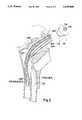
- FIGS. 1a and 1bare cross-sectional views of an intubation device according to a preferred embodiment of the invention inserted into the esophagus and trachea, respectively.
- FIG. 1cis a view similar to FIGS. 1a and 1b showing a modified form of the device inserted into the esophagus.
- FIG. 2is a side elevational view of a mask according to the invention for use with the device of FIG. 1.
- FIG. 3is a view, in cross section, of a further embodiment of a device according to the invention, including an airway and a mask which is detachably securable to the airway.
- FIGS. 1a and 1bAn advantageous embodiment of the invention is illustrated in FIGS. 1a and 1b, this embodiment being a multifunction endoesotube which can be used to insufflate the lungs, whether placed in the esophagus or trachea and which can also be employed to suction fluids from either the lungs or the stomach, depending on the passage into which it has been inserted, and to enable drugs, including antidotes, or other liquids, to be introduced into the lungs, if the device has been inserted into the trachea, or into the stomach if the device has been inserted into the esophagus.
- drugsincluding antidotes, or other liquids
- a deviceincludes a main airway tube 111 which is open at both ends to provide a longitudinal air passage that extends along its entire length, and an auxiliary tube 114 which is also open at both ends to provide a longitudinal passage that extends along its entire length.
- the side wall of tube 111is provided with an opening in which is connected the open distal end of tube 114.
- Tube 114is substantially shorter than tube 111 and both tubes have proximal ends which will extend out of the patient's mouth when the device has been fully inserted.
- Tube 111is provided with an array of openings 124 via which fluid, such as air or oxygen, can flow between the interior of, and the region, surrounding tube 111. Openings 124 may be located only on a portion of the circumference of tube 111 in a manner such that openings 124 will not be present at the side of tube 111 which is directed toward the patient's tongue.
- annular sleeve 126which is slidable in the longitudinal direction of tube 111.
- Sleeve 126is connected via a stiff wire 128 to a handle 130 which can be manipulated to move sleeve 126 between the position shown in FIG. 1a, in which openings 124 are unobstructed and the position shown in FIG. 1b in which sleeve 126 covers openings 124 in order to prevent the flow of fluid through those openings.
- Tube 111carries an inflatable balloon or cuff 140 which extends circumferentially around the outer surface of tube 111, adjacent the distal end thereof.
- the interior of balloon or cuff 140is connected to a source of inflation fluid via a small diameter tube, or lumen, which extends along main airway tube 111, in a manner similar to that described in copending application Ser. No. 07/679,197.
- balloon 140is a high compliance, low pressure balloon.
- Auxiliary tube 114is provided for introduction of a small diameter tube 150 which is open at both ends and presents a longitudinal through passage extending along its entire length.
- Tube 150has an outer diameter which is smaller than the inner diameters of tubes 111 and 114.
- tube 150is provided with a plurality of openings 152 which extend through the tube wall.
- Tube 150is of a length sufficient to permit its distal end to extend beyond the distal end of tube 111.
- the proximal end of tube 150may be adapted for connection to suction apparatus (not shown).
- an inflatable balloon or cuff 156which may be either structurally separate from tube 150, i.e. carried by a separate tube, or may be mounted on the outer wall of tube 150.
- a small diameter inflation tube, or lumen,(not shown) is connected to balloon 156 and may be mounted on the wall of tube 150, or may be independent therefrom. This lumen may also be arranged as described in copending application Ser. No. 07/679,197.
- balloon 156can be replaced by an annular cuff, or balloon, 156' mounted on the interior wall surface of tube 111, as shown in FIG. 1c. Such cuff, or balloon 156', would be deflated whenever it is desired to insert tube 150 into the distal portion of main airway tube 111.
- Each lumen for inflating a respective ballooncan be provided with a one-way valve which normally permits the passage of air or other inflating gas only in the inflating direction and which can be opened to permit balloon deflation by insertion of a syringe.
- balloon 156 or 156'can be replaced by a sealing plug made, for example, of foam rubber, mounted on tube 150.
- tube 111which proximal end may be tapered or rounded if desired, and may be lubricated, is inserted along the patient's tongue and against the posterior pharyngeal wall. Insertion of tube 111 continues until its distal end is properly positioned. Typically, this is a position in which the distal end of tube 111 is approximately 13.8 inches (35 cm) from the patient's mouth opening. During this portion of a procedure, tube 111 need not be initially assembled with a mask, to be described below.
- tube 111The proper position of the distal end of tube 111 within the patient can be verified by providing tube 111, at a small distance from its proximal end, with a first reference mark which will have a defined location relative to the patient's mouth when tube 111 has been inserted by the requisite amount.
- balloon 140is deflated.
- Tube 150may be introduced into main airway tube 111, via auxiliary tube 114, either prior to or after insertion of the device into the patient. Then, with balloon 156 deflated, as shown in FIG. 1b, tube 150 is moved along the interior of tube 111 so that the distal end of tube 150 traverses the lower portion of tube 111 while a suction force is applied, via the proximal end of tube 150, in order to withdraw from the interior of tube 111 any fluids which have accumulated therein during insertion. Openings 152 aid in the performance of this suctioning procedure.
- tube 111may be in the patient's esophagus, leading to the stomach as shown in FIGS. 1a and 1c, or in the patient's trachea, leading to the lungs, as shown in FIG. 1b.
- FIGS. 1a and 1cthe distal end of tube 111 may be in the patient's esophagus, leading to the stomach as shown in FIGS. 1a and 1c, or in the patient's trachea, leading to the lungs, as shown in FIG. 1b.
- the precise location of tube 111is determined by delivering air through tube 150, via the proximal end thereof, while using a stethoscope to listen for signs of air flowing into the stomach and visually observing the patient's chest for signs of lung inflation. During this time, since air is being introduced via tube 150, openings 124 may be unblocked so that the normal flow of air to and from the patient's lungs is unobstructed regardless of the location of tube 111.
- tube 111is in the trachea
- sleeve 126is moved to the position in which it blocks openings 124
- tube 111may be pulled back to a point at which its distal end is approximately 24 cm from the patient's mouth opening, again aided by a second reference mark on tube 111 which will be visible when tube 111 has been retracted by the proper amount, and balloon 140 is inflated by an amount appropriate to tracheal insertion, in order to seal the annular region between tube 111 and the trachea.
- the attending medical personnelcan then proceed to force air through tube 111 and into the patient's lungs. In this event, a mask is not required.
- tube 111is in the esophagus
- sleeve 126is maintained at, or moved to, the position in which openings 124 are unobstructed and balloon 156 is inflated to block the air passage through tube 111 downstream of openings 124. If balloon 156 is carried by tube 150, this requires that tube 150 be inserted into tube 111 to bring balloon 156 to a suitable location.
- a maskto be described below, is then coupled to the proximal end of tube 111 and balloon 140 is inflated by an amount appropriate for esophageal insertion. During this time, a suction force can be applied to tube 150 in order to continue to suction fluids from the patient's esophagus and stomach.
- suction tube 150can be employed to administer an appropriate medication, either to the lungs in the case of tracheal insertion or the stomach in the case of esophageal insertion.
- the inflated condition of the ballooncan be verified by applying a longitudinal force to tube 150 and observing its resistance to movement.
- the proximal end of tube 114may be closed by a suitable cap 160 which fits around tube 150.
- FIG. 2One embodiment of a mask according to the present invention is illustrated in FIG. 2. This mask may have a physical appearance similar to that of the mask illustrated in U.S. Pat. No. 4,497,318.
- mask 62differs from the mask shown in that patent in certain significant respects, as will be described in detail below.
- a collar 64which may be constituted by a molded plastic piece or a foam pad which is not constructed to be inflated.
- collar 62When collar 62 is made of a suitably configured molded plastic or foam pad, it can be made to conform satisfactorily to the patient's face, while the undesirable additional step of inflating the collar is avoided.
- collar 64may be constituted by a thin sheet of flexible material, such as a silicone rubber.
- collar 64is provided with a strap arrangement 66 which extends around to the other side of collar 64 (not visible in FIG. 2) and is used to secure mask 62 to the patient's face, with collar 64 properly positioned, so that the resuscitation procedure can be performed while the attention of the attending medical personnel need not be diverted to verify that the mask is in place.
- Mask 62further includes a cup-shaped section 70 which will fit over the patient's nose when mask 62 is in place, along with a tube 74 which is to be coupled to, and form an extension of, tube 111, and a further port (not shown) for passage of auxiliary tube 114.
- the lower, or distal, end of tube 74is flared to facilitate coupling with the proximal end of tube 111.
- Tube 74is given a free length, for example of the order of at least three inches (7.6 cm), and preferably at least four inches (10.1 cm), in order to facilitate access either by the mouth of an individual who will perform resuscitation or by a source of air or oxygen.
- tube 74is equipped with a one-way valve 76 which permits air to be blown into the patient's lungs via tube 74, but prevents the flow of air or body fluids upwardly from the patient and through the proximal end of tube 74, to thereby protect operating personnel who are performing resuscitation by mouth against contamination by viruses or other harmful organisms.
- Valve 76can have a form similar to that of the one-way valve disclosed in U.S. Pat. No. 4,998,530.
- tube 111when, during resuscitation, tube 111 is located in the patient's esophagus, air can be expelled from the patient's lungs around tube 111 and then between collar 64 and the patient's face so that the mask need not be removed to permit the patient to exhale.
- tube 114which provides a passage for insertion of suction tube 150, offers the advantage of facilitating manipulation of tube 150 and connection of that tube to either a suction source or a medication supply source, while the proximal region of tube 111 is continuously accessible for resuscitation purposes.
- FIG. 3shows an airway and mask in cross section.
- a main airway tube 211composed of a sidewall which is completely free of perforations and which is open at both ends to define a longitudinal air passage.
- auxiliary tube 214Joined to tube 211, at a location which is centered at a point approximately 2 inches (5 cm) from the proximal, or upper, end of tube 211, is the distal end of an auxiliary tube 214 which is open at its proximal end and which has a sidewall provided with a plurality of openings 224 defining lateral air passages.
- An inflatable annular cuff 240is secured to the outer wall of tube 211, in the vicinity of the distal end thereof. Cuff 240 performs the same function as cuff 140 of FIGS. 1a-1c and may be inflated in the same manner as the cuff 140 of FIGS. 1a-1c.
- a tube 250is introduced into tube 211, preferably via an opening provided in the wall of tube 211 at a location adjacent the proximal end thereof.
- Tube 250has an outer diameter which is smaller than the inner diameter of tube 211.
- Tube 250is movable longitudinally within tube 211 and is provided to perform functions similar to those described above with respect to tube 150 of FIGS. 1a-1c.
- Tube 250may be provided with lateral openings at a location corresponding to the location of openings 152 in tube 150 of FIGS. 1a-1c and tube 250 is preferably given a length sufficient to allow its distal end to extend beyond the distal end of tube 211 in order to enter the patient's stomach or lungs.
- the airway device shown in FIG. 3may be inserted into a patient in the manner described above with respect to the embodiment of FIGS. 1a-1c, and its location, whether in the esophagus or trachea, will be determined also in the manner described with reference to the embodiment of FIGS. 1a-1c.
- resuscitationcan be performed immediately via the proximal end of tube 211, after suitable inflation of cuff 240, and in this case tube 214 will perform no function.
- tube 211may then be introduced into the lungs directly via tube 214.
- cuff 240will also be inflated, and the proximal end of tube 211 may be blocked by a plug 260 to prevent the expulsion of stomach fluids.
- the tube assemblywill at this time be properly located to assure that air flowing via openings 224 will be delivered to the patient's lungs.
- the maskis composed of a thin sheet 170 of flexible material, for example of silicone rubber, having two straps 172 intended to be fitted around the victim's ears in order to hold the mask in place.
- Sheet 170 and straps 172may be constructed in the manner disclosed in U.S. Pat. No. 4,998,530.
- Sheet 170carries an extension tube 174 containing a one-way valve 176, these components corresponding in structure to tube 74 and valve 76 illustrated in FIG. 2.
- Tube 174may be coupled to the proximal end of tube 214 in the manner described above with reference to FIG. 2 relative to the coupling of tube 111.
- Sheet 170may additionally be provided with an opening 178 for access to plug 260.
- the proximal end of tube 250can project beyond sheet 170 to permit the performance of suction procedures and/or the administration of medication to the victim's stomach.
- a significant advantage of the embodiment shown in FIG. 3is its extreme structural simplicity, and in particular the absence of any movable parts, other than tube 250.
- tubes 211 and 2 14may be prominently marked, as by color coding and/or suitable labels, to indicate which tube is to be utilized if tube 211 is in the trachea or in the esophagus.
- each of tubes 211 and 2 14may be provided, in the vicinity of its proximal end, with a known sensing disc for providing an indication of end tidal CO 2 . The indication produced by each such disc can serve to indicate, or confirm, whether tube 211 is in the esophagus or the trachea.
- sheet 170may be provided with a passage for a further suction tube which will pass into the patient's mouth to permit suctioning of fluids therefrom.
- inventionswill be those conventionally used for esophageal and endotracheal intubators.
- the components of devices according to the inventioncan be constructed so as to be sterilizable and reusable, or can be constructed so as to be disposable after a single use.
Landscapes
- Health & Medical Sciences (AREA)
- Pulmonology (AREA)
- Emergency Medicine (AREA)
- Engineering & Computer Science (AREA)
- Anesthesiology (AREA)
- Biomedical Technology (AREA)
- Heart & Thoracic Surgery (AREA)
- Hematology (AREA)
- Life Sciences & Earth Sciences (AREA)
- Animal Behavior & Ethology (AREA)
- General Health & Medical Sciences (AREA)
- Public Health (AREA)
- Veterinary Medicine (AREA)
- Media Introduction/Drainage Providing Device (AREA)
Abstract
Description
Claims (19)
Priority Applications (1)
| Application Number | Priority Date | Filing Date | Title |
|---|---|---|---|
| US07/878,492US5339808A (en) | 1991-04-02 | 1992-05-05 | Endotracheal-esophageal intubation devices |
Applications Claiming Priority (2)
| Application Number | Priority Date | Filing Date | Title |
|---|---|---|---|
| US67919791A | 1991-04-02 | 1991-04-02 | |
| US07/878,492US5339808A (en) | 1991-04-02 | 1992-05-05 | Endotracheal-esophageal intubation devices |
Related Parent Applications (1)
| Application Number | Title | Priority Date | Filing Date |
|---|---|---|---|
| US67919791AContinuation-In-Part | 1991-04-02 | 1991-04-02 |
Publications (1)
| Publication Number | Publication Date |
|---|---|
| US5339808Atrue US5339808A (en) | 1994-08-23 |
Family
ID=24725951
Family Applications (1)
| Application Number | Title | Priority Date | Filing Date |
|---|---|---|---|
| US07/878,492Expired - Fee RelatedUS5339808A (en) | 1991-04-02 | 1992-05-05 | Endotracheal-esophageal intubation devices |
Country Status (1)
| Country | Link |
|---|---|
| US (1) | US5339808A (en) |
Cited By (61)
| Publication number | Priority date | Publication date | Assignee | Title |
|---|---|---|---|---|
| DE4447186A1 (en)* | 1994-12-30 | 1996-07-11 | Johann Dr Med Wittenbeck | Larynx mask for fibre optic endotracheal intubation with simultaneous artificial respiration |
| US5591130A (en)* | 1994-02-22 | 1997-01-07 | Wolfe Troy Medical, Inc. | Esophageal intubation detector with indicator |
| US5688237A (en)* | 1995-05-04 | 1997-11-18 | Cedars-Sinai Medical Center | Implantable catheter and method of use |
| US5694929A (en)* | 1996-02-26 | 1997-12-09 | Christopher; Kent L. | Method and apparatus for ventilation/oxygenation during guided insertion of an endotracheal tube |
| US5765558A (en)* | 1995-10-13 | 1998-06-16 | Siemens Elema Ab | Tracheal tube and ventilator system permitting endogenously-produced NO to be combined with respiratory gas |
| US5865176A (en)* | 1995-03-08 | 1999-02-02 | Michael Jeffrey O'Neil | Artificial airway device with sealing cuff for distal end |
| US5885248A (en)* | 1994-02-22 | 1999-03-23 | Wolf Tory Medical, Inc. | Intubation detection system with transducer based indicator |
| US5957978A (en)* | 1997-12-22 | 1999-09-28 | Hansa Medical Products, Inc. | Valved fenestrated tracheotomy tube |
| US6098617A (en)* | 1997-12-05 | 2000-08-08 | Connell; Donald G. | Device for administering/sampling inhalant/expired gases in an oro/nasopharyngeal airway |
| WO2001024859A1 (en)* | 1999-10-01 | 2001-04-12 | Evergreen Medical, Inc. | Ventilation system during guided insertion of an endotracheal tube |
| US6405725B1 (en) | 1996-02-26 | 2002-06-18 | Evergreen Medical, Inc. | Method and apparatus for ventilation/oxygenation during guided insertion of an endotracheal tube |
| US20020195103A1 (en)* | 2001-03-05 | 2002-12-26 | Government Of The United States, As Represented By The Secretary Of The Army | Intubation device and method |
| US6543446B1 (en)* | 1996-02-26 | 2003-04-08 | Evergreen Medical Incorporated | Method and apparatus for ventilation/oxygenation during guided insertion of an endotracheal tube |
| US6568388B2 (en)* | 1996-02-26 | 2003-05-27 | Evergreen Medical Incorporated | Method and apparatus for ventilation / oxygenation during guided insertion of an endotracheal tube |
| US20030101998A1 (en)* | 1997-12-24 | 2003-06-05 | Laryngeal Mask Company (Uk) Limited | Monitoring and control for a laryngeal mask airway device |
| US6626169B2 (en)* | 2001-05-17 | 2003-09-30 | Elisha Medical Technologies Ltd. | Anatomical airway ventilation intubating and resuscitation device |
| US20030185879A1 (en)* | 1999-11-05 | 2003-10-02 | Teni Boulikas | Therapy for human cancers using cisplatin and other drugs or genes encapsulated into liposomes |
| US6634354B2 (en)* | 1996-02-26 | 2003-10-21 | Evergreen Medical Incorporated | Laryngeal mask airway |
| US6668821B2 (en)* | 1996-02-26 | 2003-12-30 | Evergreen Medical Incorporated | Laryngeal mask airway |
| US6698428B2 (en) | 1996-11-06 | 2004-03-02 | Archibald I. J. Brain | Endotracheal tube construction |
| US20040060564A1 (en)* | 1997-07-25 | 2004-04-01 | Lma International Sa | Intubating laryngeal mask |
| US6722367B1 (en) | 1997-12-22 | 2004-04-20 | Hansa Medical Products, Inc. | Valved fenestrated tracheotomy tube having outer and inner cannulae |
| US6763831B2 (en)* | 2001-08-02 | 2004-07-20 | Joseph A. Sniadach | Adjustable ventilation mask for a patient |
| US20040139971A1 (en)* | 2003-01-22 | 2004-07-22 | Brain Archibald I. J. | Laryngeal mask airway device with airway tube having flattened outer circumference and elliptical inner airway passage |
| US20050051173A1 (en)* | 2003-09-08 | 2005-03-10 | Brain Archibald I. J. | Laryngeal mask airway device with position controlling tab |
| US20050051175A1 (en)* | 2003-09-10 | 2005-03-10 | Brain Archibald I. J. | Intubating laryngeal mask airway device with fiber optic assembly |
| US20050066975A1 (en)* | 1999-10-07 | 2005-03-31 | Brain Archibald I.J. | Laryngeal mask with large-bore gastric drainage |
| US20050139220A1 (en)* | 1996-02-26 | 2005-06-30 | Evergreen Medical Incorporated | Method and apparatus for ventilation / oxygenation during guided insertion of an endotracheal tube |
| US20050274383A1 (en)* | 1998-10-06 | 2005-12-15 | Brain Archibald I | Laryngeal mask airway device |
| US7159589B2 (en) | 2001-08-23 | 2007-01-09 | Indian Ocean Medical Inc. | Disposable laryngeal mask airway device |
| EP1803478A1 (en) | 2005-12-27 | 2007-07-04 | Hansa Medical Products, Inc. | Valved fenestrated tracheotomy tube having outer and inner cannulae |
| US20070277830A1 (en)* | 2003-12-18 | 2007-12-06 | Ladru Pietronella C | Respiratory Tube Having a Cuff With a Construction Zone |
| US7305985B2 (en) | 1998-08-13 | 2007-12-11 | The Laryngeal Mask Company Limited | Laryngeal mask airway device |
| USRE39938E1 (en) | 1996-03-01 | 2007-12-18 | Indian Ocean Medical, Inc. | Gastro-laryngeal mask |
| US7331346B2 (en) | 1997-12-24 | 2008-02-19 | Indian Ocean Medical, Inc. | Monitoring and control for a laryngeal mask airway device |
| US20080105263A1 (en)* | 2006-11-07 | 2008-05-08 | Jadhav Kishor B | Esophageal intubation and airway management system and method |
| US20080308108A1 (en)* | 2007-06-14 | 2008-12-18 | Melanie Paige Diorio | Oral cannula |
| US20090090366A1 (en)* | 2007-09-20 | 2009-04-09 | Cuevas Brian J | Balloon cuff tracheostomy tube |
| US20090133701A1 (en)* | 2005-05-27 | 2009-05-28 | The Laryngeal Mask Company Ltd. | Laryngeal mask airway device |
| EP1409055A4 (en)* | 2000-11-20 | 2009-09-09 | Evergreen Medical Inc | Laryngeal mask airway |
| US20090235935A1 (en)* | 2005-12-21 | 2009-09-24 | John Allen Pacey | Secretion clearing patient airway management system |
| US20090235936A1 (en)* | 2008-03-18 | 2009-09-24 | Hansa Medical Products, Inc. | Valved Fenestrated Tracheotomy Tube Having Inner and Outer Cannulae with Pressure Relief |
| US20130056007A1 (en)* | 2004-11-19 | 2013-03-07 | John A. Pacey | Secretion clearing ventilation catheter and airway management system |
| US20130146051A1 (en)* | 2011-12-09 | 2013-06-13 | Colabs | Apparatus and method for improved assisted ventilation |
| US8707956B2 (en) | 2005-12-27 | 2014-04-29 | Hansa Medical Products, Inc. | Endotracheal tube having outer and inner cannulae |
| US20150265790A1 (en)* | 2011-12-09 | 2015-09-24 | Colabs, Inc. | Apparatus and method for improved assisted ventilation |
| JP2015531300A (en)* | 2012-10-08 | 2015-11-02 | ザ クリーブランド クリニック ファウンデーションThe Cleveland ClinicFoundation | Reversible airway device and related methods for ventilating a subject |
| US9265904B2 (en) | 2009-07-06 | 2016-02-23 | Teleflex Life Sciences | Artificial airway |
| US20160192829A1 (en)* | 2013-08-15 | 2016-07-07 | Teleflex Life Sciences | Endoscopy device |
| US9528897B2 (en) | 2009-08-13 | 2016-12-27 | Chimden Medical Pty Ltd | Pressure indicator |
| US9579477B2 (en) | 2005-12-27 | 2017-02-28 | Hansa Medical Products, Inc. | Endotracheal tube having outer and inner cannulae |
| US9675772B2 (en) | 2010-10-15 | 2017-06-13 | The Laryngeal Mask Company Limited | Artificial airway device |
| US9974912B2 (en) | 2010-10-01 | 2018-05-22 | Teleflex Life Sciences Unlimited Company | Artificial airway device |
| WO2019121087A1 (en)* | 2017-12-21 | 2019-06-27 | Laerdal Medical As | Device for training tracheal suctioning |
| US10549054B2 (en) | 2011-02-02 | 2020-02-04 | Teleflex Life Sciences Unlimited Company | Artificial airway |
| US10576229B2 (en) | 2009-03-03 | 2020-03-03 | The Laryngeal Mask Company Limited | Artificial airway device |
| US10675425B2 (en) | 2013-10-08 | 2020-06-09 | The Cleveland Clinic Foundation | Reversible airway device and related method for ventilating a subject |
| US10806327B2 (en) | 2011-11-30 | 2020-10-20 | Teleflex Life Sciences Pte, Ltd. | Laryngeal mask for use with an endoscope |
| CN112354057A (en)* | 2020-11-27 | 2021-02-12 | 郴州市第一人民医院 | Laryngeal mask and monitoring devices convenient to trachea cannula moves back pipe |
| US11219729B2 (en) | 2018-03-21 | 2022-01-11 | Hansa Medical Products, Inc. | Medical device system and method including an endotracheal tube |
| US11969549B2 (en) | 2011-12-09 | 2024-04-30 | Colabs Medical, Inc. | Apparatus and method for improved assisted ventilation |
Citations (5)
| Publication number | Priority date | Publication date | Assignee | Title |
|---|---|---|---|---|
| US3874377A (en)* | 1974-06-06 | 1975-04-01 | Kenneth L Davidson | Apparatus for endotracheal and esophageal intubation |
| US4090518A (en)* | 1975-08-25 | 1978-05-23 | Elam James O | Esophago-pharyngeal airway |
| US4327720A (en)* | 1979-01-22 | 1982-05-04 | Bronson Paul A | Esophageal-endotracheal airway |
| US4497318A (en)* | 1982-04-09 | 1985-02-05 | Donmichael T A | Esophageal obturator airway |
| US5256099A (en)* | 1992-03-19 | 1993-10-26 | Elliot A. Rudell | Contact-activated pressurized water release toy |
- 1992
- 1992-05-05USUS07/878,492patent/US5339808A/ennot_activeExpired - Fee Related
Patent Citations (5)
| Publication number | Priority date | Publication date | Assignee | Title |
|---|---|---|---|---|
| US3874377A (en)* | 1974-06-06 | 1975-04-01 | Kenneth L Davidson | Apparatus for endotracheal and esophageal intubation |
| US4090518A (en)* | 1975-08-25 | 1978-05-23 | Elam James O | Esophago-pharyngeal airway |
| US4327720A (en)* | 1979-01-22 | 1982-05-04 | Bronson Paul A | Esophageal-endotracheal airway |
| US4497318A (en)* | 1982-04-09 | 1985-02-05 | Donmichael T A | Esophageal obturator airway |
| US5256099A (en)* | 1992-03-19 | 1993-10-26 | Elliot A. Rudell | Contact-activated pressurized water release toy |
Cited By (114)
| Publication number | Priority date | Publication date | Assignee | Title |
|---|---|---|---|---|
| US5885248A (en)* | 1994-02-22 | 1999-03-23 | Wolf Tory Medical, Inc. | Intubation detection system with transducer based indicator |
| US5591130A (en)* | 1994-02-22 | 1997-01-07 | Wolfe Troy Medical, Inc. | Esophageal intubation detector with indicator |
| DE4447186A1 (en)* | 1994-12-30 | 1996-07-11 | Johann Dr Med Wittenbeck | Larynx mask for fibre optic endotracheal intubation with simultaneous artificial respiration |
| US5865176A (en)* | 1995-03-08 | 1999-02-02 | Michael Jeffrey O'Neil | Artificial airway device with sealing cuff for distal end |
| US5688237A (en)* | 1995-05-04 | 1997-11-18 | Cedars-Sinai Medical Center | Implantable catheter and method of use |
| US5765558A (en)* | 1995-10-13 | 1998-06-16 | Siemens Elema Ab | Tracheal tube and ventilator system permitting endogenously-produced NO to be combined with respiratory gas |
| US20040079364A1 (en)* | 1996-02-26 | 2004-04-29 | Christopher Kent L. | Laryngeal mask airway |
| US6634354B2 (en)* | 1996-02-26 | 2003-10-21 | Evergreen Medical Incorporated | Laryngeal mask airway |
| US5964217A (en)* | 1996-02-26 | 1999-10-12 | Christopher; Kent L. | Method and apparatus for ventilation/oxygenation during guided insertion of an endotracheal tube |
| US6895966B2 (en) | 1996-02-26 | 2005-05-24 | Evergreen Medical Incorporated | Laryngeal mask airway |
| US5694929A (en)* | 1996-02-26 | 1997-12-09 | Christopher; Kent L. | Method and apparatus for ventilation/oxygenation during guided insertion of an endotracheal tube |
| US6405725B1 (en) | 1996-02-26 | 2002-06-18 | Evergreen Medical, Inc. | Method and apparatus for ventilation/oxygenation during guided insertion of an endotracheal tube |
| US20050139220A1 (en)* | 1996-02-26 | 2005-06-30 | Evergreen Medical Incorporated | Method and apparatus for ventilation / oxygenation during guided insertion of an endotracheal tube |
| US6543446B1 (en)* | 1996-02-26 | 2003-04-08 | Evergreen Medical Incorporated | Method and apparatus for ventilation/oxygenation during guided insertion of an endotracheal tube |
| US6568388B2 (en)* | 1996-02-26 | 2003-05-27 | Evergreen Medical Incorporated | Method and apparatus for ventilation / oxygenation during guided insertion of an endotracheal tube |
| US6668821B2 (en)* | 1996-02-26 | 2003-12-30 | Evergreen Medical Incorporated | Laryngeal mask airway |
| US6631713B1 (en) | 1996-02-26 | 2003-10-14 | Evergreen Medical Incorporated | Method and apparatus for ventilation/oxygenation during guided insertion of an endotracheal tube |
| USRE39938E1 (en) | 1996-03-01 | 2007-12-18 | Indian Ocean Medical, Inc. | Gastro-laryngeal mask |
| US20080142017A1 (en)* | 1996-03-01 | 2008-06-19 | The Laryngeal Mask Company Limited | Gastro-Laryngeal Mask |
| US6698428B2 (en) | 1996-11-06 | 2004-03-02 | Archibald I. J. Brain | Endotracheal tube construction |
| US20040060564A1 (en)* | 1997-07-25 | 2004-04-01 | Lma International Sa | Intubating laryngeal mask |
| US6918388B2 (en) | 1997-07-25 | 2005-07-19 | The Laryngeal Mask Company Limited | Intubating laryngeal mask |
| US6098617A (en)* | 1997-12-05 | 2000-08-08 | Connell; Donald G. | Device for administering/sampling inhalant/expired gases in an oro/nasopharyngeal airway |
| USRE41345E1 (en)* | 1997-12-22 | 2010-05-25 | Hansa Medical Products, Inc. | Valued fenestrated tracheotomy tube having outer and inner cannulae |
| US5957978A (en)* | 1997-12-22 | 1999-09-28 | Hansa Medical Products, Inc. | Valved fenestrated tracheotomy tube |
| US6722367B1 (en) | 1997-12-22 | 2004-04-20 | Hansa Medical Products, Inc. | Valved fenestrated tracheotomy tube having outer and inner cannulae |
| US20030101998A1 (en)* | 1997-12-24 | 2003-06-05 | Laryngeal Mask Company (Uk) Limited | Monitoring and control for a laryngeal mask airway device |
| US7273053B2 (en) | 1997-12-24 | 2007-09-25 | Mario Zocca | Monitoring and control for a laryngeal mask airway device |
| US7331346B2 (en) | 1997-12-24 | 2008-02-19 | Indian Ocean Medical, Inc. | Monitoring and control for a laryngeal mask airway device |
| US7305985B2 (en) | 1998-08-13 | 2007-12-11 | The Laryngeal Mask Company Limited | Laryngeal mask airway device |
| US9694150B2 (en) | 1998-08-13 | 2017-07-04 | The Laryngeal Mask Company Limited | Laryngeal mask airway device |
| US20080060655A1 (en)* | 1998-08-13 | 2008-03-13 | Lma International | Laryngeal mask airway device |
| US7156100B1 (en) | 1998-10-06 | 2007-01-02 | The Laryngeal Mask Company Ltd. | Laryngeal mask airway device |
| US20050274383A1 (en)* | 1998-10-06 | 2005-12-15 | Brain Archibald I | Laryngeal mask airway device |
| US7493901B2 (en) | 1998-10-06 | 2009-02-24 | The Laryngeal Mask Company Ltd. | Laryngeal mask airway device |
| US20060254596A1 (en)* | 1998-10-06 | 2006-11-16 | Brain Archibald I J | Laryngeal mask airway device |
| US20090007920A1 (en)* | 1998-10-06 | 2009-01-08 | The Laryngeal Mask Company Ltd. | Laryngeal mask airway device |
| US7506648B2 (en) | 1998-10-06 | 2009-03-24 | The Laryngeal Mask Company Ltd. | Laryngeal mask airway device |
| WO2001024859A1 (en)* | 1999-10-01 | 2001-04-12 | Evergreen Medical, Inc. | Ventilation system during guided insertion of an endotracheal tube |
| US20050066975A1 (en)* | 1999-10-07 | 2005-03-31 | Brain Archibald I.J. | Laryngeal mask with large-bore gastric drainage |
| US7004169B2 (en) | 1999-10-07 | 2006-02-28 | Indian Ocean Medical Inc. | Laryngeal mask with large-bore gastric drainage |
| US20030185879A1 (en)* | 1999-11-05 | 2003-10-02 | Teni Boulikas | Therapy for human cancers using cisplatin and other drugs or genes encapsulated into liposomes |
| EP1409055A4 (en)* | 2000-11-20 | 2009-09-09 | Evergreen Medical Inc | Laryngeal mask airway |
| US20100059048A1 (en)* | 2001-03-05 | 2010-03-11 | Government Of The United States As Represented By The Secretary Of The Army | Intubation device and method |
| US7552729B2 (en) | 2001-03-05 | 2009-06-30 | The United States Of America As Represented By The Secretary Of The Army | Intubation device and method |
| US20020195103A1 (en)* | 2001-03-05 | 2002-12-26 | Government Of The United States, As Represented By The Secretary Of The Army | Intubation device and method |
| US6626169B2 (en)* | 2001-05-17 | 2003-09-30 | Elisha Medical Technologies Ltd. | Anatomical airway ventilation intubating and resuscitation device |
| US6763831B2 (en)* | 2001-08-02 | 2004-07-20 | Joseph A. Sniadach | Adjustable ventilation mask for a patient |
| US20070102001A1 (en)* | 2001-08-23 | 2007-05-10 | Indian Ocean Medical Inc. | Disposable laryngeal mask airway device |
| US7159589B2 (en) | 2001-08-23 | 2007-01-09 | Indian Ocean Medical Inc. | Disposable laryngeal mask airway device |
| US20040139971A1 (en)* | 2003-01-22 | 2004-07-22 | Brain Archibald I. J. | Laryngeal mask airway device with airway tube having flattened outer circumference and elliptical inner airway passage |
| US20080053455A1 (en)* | 2003-01-22 | 2008-03-06 | Lma International | Laryngeal mask airway device with airway tube having flattened outer circumference and elliptical inner airway passage |
| US6792948B2 (en) | 2003-01-22 | 2004-09-21 | Archibald I. J. Brain | Laryngeal mask airway device with airway tube having flattened outer circumference and elliptical inner airway passage |
| US9027559B2 (en) | 2003-01-22 | 2015-05-12 | The Laryngeal Mask Company Ltd. | Laryngeal mask airway device with airway tube having flattened outer circumference and elliptical inner airway passage |
| US20050051173A1 (en)* | 2003-09-08 | 2005-03-10 | Brain Archibald I. J. | Laryngeal mask airway device with position controlling tab |
| US7134431B2 (en) | 2003-09-08 | 2006-11-14 | Indian Ocean Medical Inc. | Laryngeal mask airway device with position controlling tab |
| US20070119460A1 (en)* | 2003-09-10 | 2007-05-31 | Brain Archibald I | Intubating laryngeal mask airway device with fiber optic assembly |
| US20050051175A1 (en)* | 2003-09-10 | 2005-03-10 | Brain Archibald I. J. | Intubating laryngeal mask airway device with fiber optic assembly |
| US7128071B2 (en) | 2003-09-10 | 2006-10-31 | Indian Ocean Medical Inc. | Intubating laryngeal mask airway device with fiber optic assembly |
| US7896007B2 (en) | 2003-09-10 | 2011-03-01 | Indian Ocean Medical Inc. | Intubating laryngeal mask airway device with fiber optic assembly |
| US20070277830A1 (en)* | 2003-12-18 | 2007-12-06 | Ladru Pietronella C | Respiratory Tube Having a Cuff With a Construction Zone |
| US20130056007A1 (en)* | 2004-11-19 | 2013-03-07 | John A. Pacey | Secretion clearing ventilation catheter and airway management system |
| US9522245B2 (en) | 2005-05-27 | 2016-12-20 | The Laryngeal Mask Company Ltd. | Laryngeal mask airway device and method of manufacture |
| US20100059061A1 (en)* | 2005-05-27 | 2010-03-11 | The Laryngeal Mask Company Ltd. | Laryngeal mask airway device and method of manufacture |
| US9498591B2 (en) | 2005-05-27 | 2016-11-22 | The Laryngeal Mask Company Ltd. | Laryngeal mask airway device with a support for preventing occlusion |
| US9662465B2 (en) | 2005-05-27 | 2017-05-30 | The Laryngeal Mask Company Ltd. | Laryngeal mask airway device |
| US20090133701A1 (en)* | 2005-05-27 | 2009-05-28 | The Laryngeal Mask Company Ltd. | Laryngeal mask airway device |
| US8783256B2 (en) | 2005-05-27 | 2014-07-22 | The Laryngeal Mask Company Ltd. | Laryngeal mask airway device |
| US20180318536A1 (en)* | 2005-12-21 | 2018-11-08 | Foster Pepper PLLC | Secretion clearing patient airway management system |
| US20090235935A1 (en)* | 2005-12-21 | 2009-09-24 | John Allen Pacey | Secretion clearing patient airway management system |
| US20210346626A1 (en)* | 2005-12-21 | 2021-11-11 | Foster Garvey Pc | Secretion clearing patient airway management system |
| US10940282B2 (en) | 2005-12-21 | 2021-03-09 | Foster Pepper PLLC | Secretion clearing patient airway management system |
| EP1803478A1 (en) | 2005-12-27 | 2007-07-04 | Hansa Medical Products, Inc. | Valved fenestrated tracheotomy tube having outer and inner cannulae |
| US8707956B2 (en) | 2005-12-27 | 2014-04-29 | Hansa Medical Products, Inc. | Endotracheal tube having outer and inner cannulae |
| EP1961441A2 (en) | 2005-12-27 | 2008-08-27 | Hansa Medical Products, Inc. | Valved fenestrated tracheotomy tube having outer and inner cannulae |
| US7987851B2 (en) | 2005-12-27 | 2011-08-02 | Hansa Medical Products, Inc. | Valved fenestrated tracheotomy tube having outer and inner cannulae |
| US20110011406A1 (en)* | 2005-12-27 | 2011-01-20 | Hansa Medical Products, Inc. | Valved Fenestrated Tracheotomy Tube Having Outer and Inner Cannulae |
| US9579477B2 (en) | 2005-12-27 | 2017-02-28 | Hansa Medical Products, Inc. | Endotracheal tube having outer and inner cannulae |
| US20080105263A1 (en)* | 2006-11-07 | 2008-05-08 | Jadhav Kishor B | Esophageal intubation and airway management system and method |
| US20080308108A1 (en)* | 2007-06-14 | 2008-12-18 | Melanie Paige Diorio | Oral cannula |
| US20090090366A1 (en)* | 2007-09-20 | 2009-04-09 | Cuevas Brian J | Balloon cuff tracheostomy tube |
| US8607795B2 (en)* | 2007-09-20 | 2013-12-17 | Kimberly-Clark Worldwide, Inc. | Balloon cuff tracheostomy tube |
| US20090235936A1 (en)* | 2008-03-18 | 2009-09-24 | Hansa Medical Products, Inc. | Valved Fenestrated Tracheotomy Tube Having Inner and Outer Cannulae with Pressure Relief |
| US10576229B2 (en) | 2009-03-03 | 2020-03-03 | The Laryngeal Mask Company Limited | Artificial airway device |
| US9265904B2 (en) | 2009-07-06 | 2016-02-23 | Teleflex Life Sciences | Artificial airway |
| US10576230B2 (en) | 2009-07-06 | 2020-03-03 | Teleflex Life Sciences Unlimited Company | Artificial airway |
| US10126197B2 (en) | 2009-08-13 | 2018-11-13 | Teleflex Life Sciences | Pressure indicator |
| US9528897B2 (en) | 2009-08-13 | 2016-12-27 | Chimden Medical Pty Ltd | Pressure indicator |
| US9974912B2 (en) | 2010-10-01 | 2018-05-22 | Teleflex Life Sciences Unlimited Company | Artificial airway device |
| US10842962B2 (en) | 2010-10-15 | 2020-11-24 | Teleflex Life Sciences Pte. Ltd. | Artificial airway device |
| US9675772B2 (en) | 2010-10-15 | 2017-06-13 | The Laryngeal Mask Company Limited | Artificial airway device |
| US10549054B2 (en) | 2011-02-02 | 2020-02-04 | Teleflex Life Sciences Unlimited Company | Artificial airway |
| US10806327B2 (en) | 2011-11-30 | 2020-10-20 | Teleflex Life Sciences Pte, Ltd. | Laryngeal mask for use with an endoscope |
| US10485940B2 (en) | 2011-12-09 | 2019-11-26 | Colabs Medical, Inc. | Apparatus and method for improved assisted ventilation |
| US20150265790A1 (en)* | 2011-12-09 | 2015-09-24 | Colabs, Inc. | Apparatus and method for improved assisted ventilation |
| US9220858B2 (en) | 2011-12-09 | 2015-12-29 | Colabs, Inc. | Apparatus and method for improved assisted ventilation |
| US9802014B2 (en)* | 2011-12-09 | 2017-10-31 | Colabs, Inc. | Apparatus and method for improved assisted ventilation |
| US12364827B2 (en) | 2011-12-09 | 2025-07-22 | Colabs Medical, Inc. | Apparatus and method for improved assisted ventilation |
| US9757530B2 (en)* | 2011-12-09 | 2017-09-12 | Colabs, Inc. | Apparatus and method for improved assisted ventilation |
| US8776796B2 (en)* | 2011-12-09 | 2014-07-15 | Colabs, Inc. | Apparatus and method for improved assisted ventilation |
| US11969549B2 (en) | 2011-12-09 | 2024-04-30 | Colabs Medical, Inc. | Apparatus and method for improved assisted ventilation |
| US11633558B2 (en) | 2011-12-09 | 2023-04-25 | Colabs Medical, Inc. | Apparatus and method for improved assisted ventilation |
| US10709855B2 (en) | 2011-12-09 | 2020-07-14 | Colabs Medical, Inc. | Apparatus and method for improved assisted ventilation |
| US11511061B2 (en) | 2011-12-09 | 2022-11-29 | Colabs Medical, Inc. | Apparatus and method for improved assisted ventilation |
| US20130146051A1 (en)* | 2011-12-09 | 2013-06-13 | Colabs | Apparatus and method for improved assisted ventilation |
| JP2015531300A (en)* | 2012-10-08 | 2015-11-02 | ザ クリーブランド クリニック ファウンデーションThe Cleveland ClinicFoundation | Reversible airway device and related methods for ventilating a subject |
| US10556077B2 (en) | 2012-10-08 | 2020-02-11 | The Cleveland Clinic Foundation | Reversible airway device and related method for ventilating a subject |
| US20160192829A1 (en)* | 2013-08-15 | 2016-07-07 | Teleflex Life Sciences | Endoscopy device |
| US10722104B2 (en)* | 2013-08-15 | 2020-07-28 | Teleflex Life Sciences Pte. Ltd. | Endoscopy device |
| US10675425B2 (en) | 2013-10-08 | 2020-06-09 | The Cleveland Clinic Foundation | Reversible airway device and related method for ventilating a subject |
| WO2019121087A1 (en)* | 2017-12-21 | 2019-06-27 | Laerdal Medical As | Device for training tracheal suctioning |
| US10636324B2 (en) | 2017-12-21 | 2020-04-28 | Laerdal Medical As | Device for training tracheal suctioning |
| US11219729B2 (en) | 2018-03-21 | 2022-01-11 | Hansa Medical Products, Inc. | Medical device system and method including an endotracheal tube |
| CN112354057A (en)* | 2020-11-27 | 2021-02-12 | 郴州市第一人民医院 | Laryngeal mask and monitoring devices convenient to trachea cannula moves back pipe |
Similar Documents
| Publication | Publication Date | Title |
|---|---|---|
| US5339808A (en) | Endotracheal-esophageal intubation devices | |
| US5499625A (en) | Esophageal-tracheal double lumen airway | |
| EP0596517B1 (en) | Emergency resuscitation apparatus | |
| US3905361A (en) | Apparatus for sealing the esophagus and providing artificial respiration and evacuating the stomach | |
| US4280492A (en) | Tracheostomy tube | |
| US3788326A (en) | Distally perforated catheter for use in ventilating system | |
| US5623921A (en) | Laryngeal mask airway and method for its use | |
| US5964217A (en) | Method and apparatus for ventilation/oxygenation during guided insertion of an endotracheal tube | |
| US7938118B2 (en) | Combination laryngeal mask airway with dual blocking and fluid removal features and method | |
| US4256099A (en) | Two-tube resuscitation system | |
| US6626169B2 (en) | Anatomical airway ventilation intubating and resuscitation device | |
| US4231365A (en) | Emergency resuscitation apparatus | |
| US3874377A (en) | Apparatus for endotracheal and esophageal intubation | |
| US5791341A (en) | Oropharyngeal stent with laryngeal aditus shield and nasal airway with laryngeal aditus shield | |
| EP0746368B1 (en) | Cuffed oro-pharyngeal airway | |
| US6668821B2 (en) | Laryngeal mask airway | |
| US6631713B1 (en) | Method and apparatus for ventilation/oxygenation during guided insertion of an endotracheal tube | |
| US4497318A (en) | Esophageal obturator airway | |
| US5291882A (en) | Multi-lumen ITPV endotracheal tube | |
| EP0448878A2 (en) | Artificial airway device | |
| US20140128676A1 (en) | Non-Rebreathing Mask With Closeable Aperture and Auxilliary Flow Tube | |
| WO1998023317A1 (en) | Artificial respiration device | |
| WO1997007846A1 (en) | Coupling device for a stethoscope and an endotracheal tube | |
| WO1997007846A9 (en) | Coupling device for a stethoscope and an endotracheal tube | |
| US3948255A (en) | Apparatus for endotracheal and esophageal intubation |
Legal Events
| Date | Code | Title | Description |
|---|---|---|---|
| AS | Assignment | Owner name:BRUNSWICK BIOMEDICAL TECHNOLOGIES, INC., MASSACHUS Free format text:ASSIGNMENT OF ASSIGNORS INTEREST.;ASSIGNOR:MICHAEL, T. ANTHONY;REEL/FRAME:006112/0912 Effective date:19920407 | |
| AS | Assignment | Owner name:MICHAEL, T. ANTHONY DON, CALIFORNIA Free format text:ASSIGNMENT OF ASSIGNORS INTEREST;ASSIGNOR:BRUNSWICK BIOMEDICAL TECHNOLOGIES, INC.;REEL/FRAME:007012/0009 Effective date:19940406 | |
| AS | Assignment | Owner name:GREENFIELD MEDICAL PRODUCTS, INC., MASSACHUSETTS Free format text:ASSIGNMENT OF ASSIGNORS INTEREST;ASSIGNOR:DON MICHAEL, T. ANTHONY;REEL/FRAME:008334/0030 Effective date:19961213 | |
| AS | Assignment | Owner name:GREENFIELD MEDICAL TECHNOLOGIES, INC., MASSACHUSET Free format text:ASSIGNMENT OF ASSIGNORS INTEREST;ASSIGNOR:GREENFIELD MEDICAL PRODUCTS, INC.;REEL/FRAME:008447/0466 Effective date:19970310 | |
| FPAY | Fee payment | Year of fee payment:4 | |
| AS | Assignment | Owner name:MICHAEL, T. ANTHONY DON, M.D., CALIFORNIA Free format text:ASSIGNMENT OF ASSIGNORS INTEREST;ASSIGNOR:GREENFIELD MEDICAL TECHNOLOGIES, INC.;REEL/FRAME:010321/0160 Effective date:19991008 | |
| FPAY | Fee payment | Year of fee payment:8 | |
| AS | Assignment | Owner name:DON MICHAEL INTERNATIONAL, LLC, CALIFORNIA Free format text:ASSIGNMENT OF ASSIGNORS INTEREST;ASSIGNOR:MICHAEL, T. ANTHONY DON, M.D.;REEL/FRAME:017353/0670 Effective date:19980101 | |
| REMI | Maintenance fee reminder mailed | ||
| LAPS | Lapse for failure to pay maintenance fees | ||
| STCH | Information on status: patent discontinuation | Free format text:PATENT EXPIRED DUE TO NONPAYMENT OF MAINTENANCE FEES UNDER 37 CFR 1.362 | |
| FP | Lapsed due to failure to pay maintenance fee | Effective date:20060823 |