US5339074A - Very low frequency tracking system - Google Patents
Very low frequency tracking systemDownload PDFInfo
- Publication number
- US5339074A US5339074AUS07/759,538US75953891AUS5339074AUS 5339074 AUS5339074 AUS 5339074AUS 75953891 AUS75953891 AUS 75953891AUS 5339074 AUS5339074 AUS 5339074A
- Authority
- US
- United States
- Prior art keywords
- instrumentality
- identifying
- radio frequency
- station
- proximity sensor
- Prior art date
- Legal status (The legal status is an assumption and is not a legal conclusion. Google has not performed a legal analysis and makes no representation as to the accuracy of the status listed.)
- Expired - Lifetime
Links
Images


Classifications
- G—PHYSICS
- G06—COMPUTING OR CALCULATING; COUNTING
- G06K—GRAPHICAL DATA READING; PRESENTATION OF DATA; RECORD CARRIERS; HANDLING RECORD CARRIERS
- G06K1/00—Methods or arrangements for marking the record carrier in digital fashion
- G—PHYSICS
- G03—PHOTOGRAPHY; CINEMATOGRAPHY; ANALOGOUS TECHNIQUES USING WAVES OTHER THAN OPTICAL WAVES; ELECTROGRAPHY; HOLOGRAPHY
- G03F—PHOTOMECHANICAL PRODUCTION OF TEXTURED OR PATTERNED SURFACES, e.g. FOR PRINTING, FOR PROCESSING OF SEMICONDUCTOR DEVICES; MATERIALS THEREFOR; ORIGINALS THEREFOR; APPARATUS SPECIALLY ADAPTED THEREFOR
- G03F7/00—Photomechanical, e.g. photolithographic, production of textured or patterned surfaces, e.g. printing surfaces; Materials therefor, e.g. comprising photoresists; Apparatus specially adapted therefor
- G03F7/70—Microphotolithographic exposure; Apparatus therefor
- G03F7/70483—Information management; Active and passive control; Testing; Wafer monitoring, e.g. pattern monitoring
- G03F7/70491—Information management, e.g. software; Active and passive control, e.g. details of controlling exposure processes or exposure tool monitoring processes
- G03F7/70541—Tagging, i.e. hardware or software tagging of features or components, e.g. using tagging scripts or tagging identifier codes for identification of chips, shots or wafers
- G—PHYSICS
- G01—MEASURING; TESTING
- G01S—RADIO DIRECTION-FINDING; RADIO NAVIGATION; DETERMINING DISTANCE OR VELOCITY BY USE OF RADIO WAVES; LOCATING OR PRESENCE-DETECTING BY USE OF THE REFLECTION OR RERADIATION OF RADIO WAVES; ANALOGOUS ARRANGEMENTS USING OTHER WAVES
- G01S13/00—Systems using the reflection or reradiation of radio waves, e.g. radar systems; Analogous systems using reflection or reradiation of waves whose nature or wavelength is irrelevant or unspecified
- G01S13/74—Systems using reradiation of radio waves, e.g. secondary radar systems; Analogous systems
- G01S13/75—Systems using reradiation of radio waves, e.g. secondary radar systems; Analogous systems using transponders powered from received waves, e.g. using passive transponders, or using passive reflectors
- G—PHYSICS
- G03—PHOTOGRAPHY; CINEMATOGRAPHY; ANALOGOUS TECHNIQUES USING WAVES OTHER THAN OPTICAL WAVES; ELECTROGRAPHY; HOLOGRAPHY
- G03F—PHOTOMECHANICAL PRODUCTION OF TEXTURED OR PATTERNED SURFACES, e.g. FOR PRINTING, FOR PROCESSING OF SEMICONDUCTOR DEVICES; MATERIALS THEREFOR; ORIGINALS THEREFOR; APPARATUS SPECIALLY ADAPTED THEREFOR
- G03F7/00—Photomechanical, e.g. photolithographic, production of textured or patterned surfaces, e.g. printing surfaces; Materials therefor, e.g. comprising photoresists; Apparatus specially adapted therefor
- G03F7/70—Microphotolithographic exposure; Apparatus therefor
- G03F7/70691—Handling of masks or workpieces
- G03F7/70733—Handling masks and workpieces, e.g. exchange of workpiece or mask, transport of workpiece or mask
- G03F7/7075—Handling workpieces outside exposure position, e.g. SMIF box
- G—PHYSICS
- G07—CHECKING-DEVICES
- G07C—TIME OR ATTENDANCE REGISTERS; REGISTERING OR INDICATING THE WORKING OF MACHINES; GENERATING RANDOM NUMBERS; VOTING OR LOTTERY APPARATUS; ARRANGEMENTS, SYSTEMS OR APPARATUS FOR CHECKING NOT PROVIDED FOR ELSEWHERE
- G07C9/00—Individual registration on entry or exit
- G07C9/20—Individual registration on entry or exit involving the use of a pass
- G07C9/28—Individual registration on entry or exit involving the use of a pass the pass enabling tracking or indicating presence
Definitions
- an eventsuch as a person commencing to operate a personal computer or a computer terminal, or such as an item of material or a container residing at a particular location.
- Such an identificationmay be recorded and may initiate other events or sequences, and may initiate gathering of other information, such as the time and location of the event or such as the nature of the events to follow.
- Identification tags on such an instrumentalityhave been previously known to incorporate a transponder and to emit a radio frequency (hereafter r.f.) signal in response to an r.f. transmitted inquiry, to identify the tag.
- r.f.radio frequency
- r.f. transmissionsmay be closely coupled with personnel in confined locations. It is believed that such r.f. transmissions may have some adverse effects upon such personnel.
- An object of the inventionis to provide a new and improved device for identifying an instrumentality, such as a person or an object, through the use of r.f. signal transmitting and receiving devices coupled together while minimizing possible adverse effects of such r.f. transmissions on nearby persons and nearby environment.
- a feature of the inventionis the provision of the method and means for identifying a person who assumes a position for operating an apparatus, such as the trackball, at a computer terminal.
- a tag incorporating a programmed transponderis attached to the person's wrist and will transmit an identifying unique r.f. signal in response to an r.f. transmitted inquiry from a computer-controlled identifying station incorporated into a portion of such apparatus, such as a nest for the trackball.
- An advantage of identifying a person in the manner set forthis that the person may conveniently wear a wristband incorporating such a tag without interfering with other normal activities of the person.
- the resulting identificationmay be simply recorded or may be used to permit or cause the computer to perform certain functions without operating a keyboard or other facility.
- Another feature of the inventionis the provision of a proximity sensor at an identifying station to sense the presence of an instrumentality, i.e., a person or object carrying a tag with a programmed transponder, in a position to be identified.
- the identifying stationincorporates a computer chip and r.f. sensor which is programmed to limit the length of the r.f. transmissions to obtain the identification of the instrumentality, and to also prevent additional transmissions after the instrumentality has been identified.
- the identifying stationIn obtaining the identification of such an instrumentality, the identifying station is polled sequentially, along with other identifying stations, by a host computer for a report.
- the identifying stationresponds to the polling inquiry, and to an indication from the proximity sensor that the instrumentality is present, by first initiating a momentary transmitted inquiry, to which the transponder of the tag produces an identifying response.
- the identifying stationimmediately reports to the host computer the identity of the tag on the instrumentality; and at the same time, the identifying station sets a one-time flag that the tag identity has been read and reported.
- the proximity sensoragain indicates the presence of the instrumentality, but the identifying station recognizes the one-time flag and simply reports that instrumentality is still sensed to be present, but that its identity has already been read and reported.
- the proximity sensorWhen the instrumentality has been removed from the identifying station, the proximity sensor, after a short delay, will permit the one-time flag to be cleared and permit the identifying station to be ready to again receive another instrumentality to be identified.
- the short delaypermits the instrumentality previously identified to be briefly removed from the identifying station and then returned again without permitting the identifying station to generate and transmit an r.f. inquiry.
- a principal advantage of limiting the r.f. transmitted inquiry to only those occasions when an instrumentality is present,is to minimize the existence of r.f. fields around operating personnel and equipment that may be sensitive to such r.f. fields.
- the advantage of limiting the repeating of such r.f. transmissionsis to minimize the possible hazards of such excessive r.f. transmissions.
- polling of the several stationsis not slowed by excessive identifying activity at each station.
- One or more photodiodessense the physical presence of the instrumentality.
- the instrumentalityobstructs transmission of ambient light to the photodiode, which indicates a change in its circuit. No moving parts are utilized in this form.
- This form of proximity sensoris particularly useful in detecting the presence of a person's hand or arm.
- a principal advantage in the use of photodiodesis the prevention of generating any particles which are contaminants in the processing of silicon wafers.
- Another principal advantage in the use of photodiodes to sense the presence of the instrumentalityis that no additional activity by a person is needed to induce the identifying functions. There are no buttons to operate and no other physical activity needed. The intended reading of the identification tag with the transponder is not affected.
- a mechanical feelermay be operated by an object at the identifying station, but the feeler, which operates with a minimum of physical force, minimizes the generation of particles.
- An additional feature of the inventionis a supporting nest upon which a portion of the instrumentality, such as a person's arm, may rest as the expected function is being performed. The presence of the person's arm may be detected so that the identity of its identifying tag may be determined. The nest will hold the instrument in a certain position so that the person's hand and arm are required to have a particular location and orientation.
- a portion of the instrumentalitysuch as a person's arm
- Such a supporting nestprovides the advantage of establishing a positive position between the identifying tag which incorporates the transponder, and the r.f. antenna which is a part of the identifying station.
- a further feature of the inventionis the provision of an LCD display on the nest for the box which may be programmed to display a message relevant to the contents of the box.
- the silicon wafers in the boxmay be at an intermediate stage of processing and the message may indicate the required next destination or station for further processing.
- Still another featureis the ornamental design of the nest for the trackball device, and of the nest for the box.
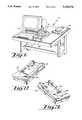
- FIG. 1is a perspective view of the identifying stations and the computer terminal.
- FIG. 2is a right side perspective view of a trackball nest.
- FIG. 3is a left side perspective view of the nest for a trackball.
- FIG. 4is an elevation view of a trackball nest showing it in use.
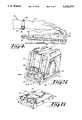
- FIG. 5is a perspective view of a typical box being identified and its nest.
- FIG. 6is a right side perspective view of a nest for a box.
- FIG. 7is a left side perspective view of a nest for a box.
- FIG. 8is a detail section view of a portion of a box nest and a portion of a box resting thereon.
- FIG. 9is a left side perspective view of a wrist tag incorporating a transponder.
- FIG. 10is a right side perspective view of the wrist tag incorporating a transponder.
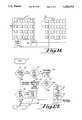
- FIG. 11is a block diagram showing multiple identifying stations for various instrumentalities, being polled by a host computer.
- FIG. 12is a diagrammatic sketch showing the relation of the major components of the instrumentality identifying station to the circuit board contained in a nest for a trackball.
- FIG. 13is a flow diagram indicating the identifying functions being performed.
- FIG. 14is a diagrammatic sketch showing the relation of the major components of the instrumentality identifying station to the circuit board contained in a nest for a box.
- the tracking system of the present inventionis indicated in general in FIG. 1 by the numeral 10, and is capable of identifying an instrumentality which may be in the form of a container or box 11 for storing or shipping silicon wafers contained in a wafer carrier as illustrated in FIG. 5; or the instrumentality may comprise a person 12 whose hand 13 is illustrated in FIG. 4.
- a container or box 11 of FIG. 5such a box may be one of many boxes containing silicon wafers at various stages of processing and being stored between process steps.
- it is important to keep track of such boxesso that they may be efficiently handled and moved through the processing system during the manufacture of chips from the wafers being stored in the containers.
- the person 12may be identified as the person assumes a position to work at a workstation, and the identification of the person may be used for various purposes, such as to boot-up a computer or to allow access into certain software programs, etc.
- the containers or boxes 11 which contain wafers being processedwould ordinarily be stored in a clean room 14 illustrated diagrammatically in FIG. 11 wherein a multiplicity of identifying stations 15 are available for identifying such containers or other vehicles related to the processing of wafers. Similarly, a plurality of identifying stations 16 are available for identifying persons at their various workstations.
- the identifying stations 15, 16,are under the control of a host computer 17 which regularly and repeatedly polls each of the identifying stations 15, 16 seeking a response to determine the presence and identity of an instrumentality at such an identifying station.
- a power supply 18is also provided, also connected to each of the identifying stations, 15, 16 to supply the necessary DC power to these stations.
- the identifying stations 15are illustrated in the form of a nest 19 upon which the container 11 may rest in a predetermined and specified position so that its presence may be sensed.
- the identifying stations 16may also take a number of different forms, but in the form illustrated, the identifying stations 16 take the form of a trackball nest 20 to carry a trackball device or control 21 in such a position that the person 12 must orient the operating hand 13 in a predetermined relation to the nest 20 in order to operate the trackball device 21.
- a trackballmay control a computer in a manner similar to a "mouse", except that the trackball device has the control ball 22 in a stationary but upright position so that it can be turned by the fingers of the person's hand; and the trackball device also has additional controls such as a pressure operated button 23 to provide additional control functions for the computer or terminal.
- Each of the instrumentalities 12, 11,carries an identifying tag 24, 25, each of which confines a programmed transponder 26, 27 which incorporates an r.f. antenna and which generates a unique r.f. identifying signal in response to an r.f. transmitted inquiry from a remote location outside of the respective tag 24, 25.
- the tag 24is carried by a strap 28 on the person's wrist; and the tag 25 is adhered directly to the side of the box 11.
- both of the identifying stations 15, 16are substantially identical to each other with certain minor exceptions, as will be noted.
- Each of the identifying stationshas a circuit board 29 contained within the respective housing or nest, 19, 20; and the circuit board has a pair of cable connections 30 and 31 connecting it to the circuit board of the next adjacent identifying station and to the host computer 17 and the power supply 18.
- the cable connection 30transmits data in and out, to and from the host computer; and the cable connection 31 transmits power from the power supply 18 to the circuit board 29 and also transmits data in and out, and to and from the next identifying station.
- all of the identifying stationsare essentially series connected with the host computer and with the power supply, substantially as illustrated in FIG. 11.
- Each of the circuit boardsalso includes an r.f. sensor 32 performing multiple functions as hereafter described, and is importantly connected to the antenna 33.1, 33.2.
- the respective antennaIn the trackball nest 20 of identifying station 16, the respective antenna is indicated by the numeral 33.1; and in the container nest 19 of identifying station 15, the respective antenna is identified by the numeral 33.2. Both of the antennas 33.1 and 33.2 are physically located in their respective nest at a position closely adjacent the location of the respective tag 24, 25 of the instrumentality being identified.
- Each of the identifying stations 15, 16has a proximity sensor 35 or 34, wherein the proximity sensor 34 is utilized in the identifying station 16 for identifying the person 12; and the proximity sensor 35 is utilized in the identifying station 15 in nest 19 in relation to the container or box 11 being identified therein.
- the proximity sensor 34 of identifying station 16embodies a pair of photodiodes 36 on the upper surface of the housing or nest 20 so that the person's wrist or hand 13 will obstruct or interfere with ambient light reaching the photodiodes 36 when the person's hand 13 is in position to operate the trackball device 21. In this way, the proximity sensor 34 will sense the presence of the person 12 at the trackball station.
- the proximity sensor 34is connected, in the identifying station 16, to the respective circuit board 29 and the r.f. sensor 32 thereof. Whereas one of the functions of the r.f. sensor is to generate an r.f. signal to be transmitted by the antenna 33.1, the proximity sensor 34 will prevent the r.f. sensor from generating the r.f. signal when the proximity sensor 34 senses the absence of the instrumentality or person's wrist 13 at the identifying station.
- the proximity sensor 35utilized in conjunction with the identifying station 15 and in the nest 19, also utilizes a photodiode 37, but in the proximity sensor 35, the photodiode 37 is not exposed to ambient light, but is exposed to the light generated by an LED light source 38.
- the light from the LEDis obstructed by a movable armature 39 within the proximity sensor 35 and movable by a box-engaging feeler or movable button 40 which is engaged by the surface of the container 11 when it is properly mounted and carried upon the nest 19.
- the proximity sensor 35is connected to the circuit board 29 and particularly to the r.f. sensor 32 thereof; and the proximity sensor 35 will alternately permit or prevent the r.f. sensor 32 from generating an r.f.
- the box 11When the feeler 40 is not engaged by a box 11, the box 11 is absent from the nest 19 and the armature 39 will permit transmission of light from the LED light source 38 to the photodiode 37; and in this condition, the proximity sensor 35, which is connected to the r.f. sensor 32, prevents the r.f. sensor from generating the r.f. signal to be transmitted by the antenna.
- the feeler 40when the feeler 40 is engaged by the box properly placed on the nest 19, the feeler 40 moves the armature 39 as to obstruct light from the LED light source 38, and the obstruction and reduced light is sensed by the photodiode 37 so that in this condition, the proximity sensor 35, which is connected to the r.f. sensor 32, permits the r.f. sensor to generate and transmit the r.f. signal to and by the antenna.
- the LCD 41.2is also connected to the r.f. sensor 32 as shown in FIG. 14.
- the trackball nestis illustrated so that the ornamental design of it is apparent.
- the rectangular shape of recess 42 and the relative locations of the recess 42 and photodiodes 36are utilitarian, and the balance of the aesthetic design is ornamental.
- the upper portion 20.1 of the housinghas an elongate recess 42 therein to receive the trackball unit 21, and as will be apparent, the photodiodes 36 protrude through the upper portion of the housing to respond to ambient light above the trackball nest.
- FIGS. 6, 7 and 8illustrate the detailed shape of the nest 19 for the container 11.
- the upper portion 43 of the housing of nest 19has protruding insert portions 44 which fit into and are received into the bottom wall portion 11.1 of the box when the box is rested upon the nest 19.
- the feeler 40 of the proximity sensorprotrudes through the upper portion 43 of the nest 19 as to be engaged by a portion of the container when the container rests upon the nest.
- FIGS. 9 and 10The specific design of the tag 24, attachable to a person's wrist, is illustrated in FIGS. 9 and 10 from different sides.
- the central portion 45 of the tagcarries the transponder 26 which is shown schematically in dotted lines in FIG. 9.
- the end portions 46 of the tag 24have openings 47 to facilitate attaching the wristband or strap 28 thereto.
- the host computer 17regularly polls all of the identifying stations 15, 16 to determine from these stations whether an instrumentality has been identified and to determine whether an instrumentality is present at one of the identifying stations to be identified.
- the identifying stationsare polled in sequence for responses.
- the host computer 17 and the r.f. sensor 32 of a particular identifying station 15, 16senses the condition of the proximity sensor to determine whether the proximity sensor 32, see box 52, indicates a true condition, i.e., the presence of an instrumentality. If the proximity sensor responds "no" or "not true", i.e., the absence of any instrumentality at the identifying station, an additional inquiry is made as to whether a one-time flag has been set, see box 53, and if the response to that is in the negative, the host computer simply passes the identifying station, exits, see box 54, and goes on to the next station.
- the r.f. sensor 32will determine that the proximity sensor reports "true", i.e., the presence of an instrumentality, and will then determine whether a one-time flag has yet been set, see box 55, and if the one-time flag has not yet been set, the r.f. sensor will activate the antenna 33 of the identifying station, see box 56, causing generation of an r.f. transmitted inquiry of the adjacent tag 24 or 25.
- the transponder in the tag24 or 25
- the transponder in the tagwill generate an r.f. identifying signal momentarily, which is received by the antenna and the r.f. sensor 32.
- the r.f. sensor 32will determine whether the identification of the instrumentality 24 or 25 has been accurately read, see box 57; and if the response is "yes", the tag has been satisfactorily read, then the r.f. sensor will set a one-time flag, see box 58, and will report the tag number, see box 59, to the host computer. In the event that the tag was not accurately read, and responds "no", then the one-time flag is not set, and the inquiry from the host computer is terminated, see box 54, subject to polling of the identifying station in the next polling sequence by the host computer.
- a one-time flag of this actionwill have been set in the r.f. sensor.
- the r.f. sensor 32will again inquire as to whether the one-time flag has been set, see box 55, and because the one-time flag has been set, the response to the inquiry is "yes", and whereupon the r.f. sensor 32 will report to the host computer that the proximity sensor reports "true”, but the tag has been read before, see box 60, so that no additional message need be sent to the host computer. Accordingly, the r.f. signal will not be generated and transmitted at the antenna, and the transponder of the tag on the instrumentality will not respond.
- the proximity sensorwill again report "no", see box 52, i.e., the absence of an instrumentality; and subsequently the r.f. sensor 32 will inquire as to whether the one-time flag has been set, see box 53 and if the report is "yes", the one-time flag will be cleared, see box 61, so that a report to the host computer will simply be that there is no instrumentality at the identifying station to be identified.
- the proximity sensorwill continue to report "true”, i.e., "yes”, indicating the presence of the instrumentality, whereupon the r.f. sensor will again report to the host computer that the proximity sensor reports "true”, but the identity of the tag has been read before.
- the host computermay transmit a message to the r.f. sensor of the appropriate identifying station which is to be displayed at the LCD display in the window 41.
- the r.f. transmitted inquiry from the r.f. sensorwill be transmitted only momentarily, i.e., for approximately 60 microseconds, see box 56, as to minimize the exposure of nearby persons and media to this r.f. transmission; and then the transponder of the identifying tag will also only transmit only momentarily, obtaining the same advantage of minimal transmission.
- the identity of the unique signal from the transponder in the taghas been identified and therefore the instrumentality has been identified, no additional r.f. transmissions will be emanated from either the antenna of the identifying station or from the transponder on the instrumentality.
- the present disclosureis of a method of identifying an instrumentality, i.e., a person or an object such as a container filled with semiconductor wafers; attaching a programmed transponder to the instrumentality to be identified, and wherein the transponder is preprogrammed for transmitting a unique r.f. identifying signal, sensing the proximity or absence of the instrumentality at the identifying station, momentarily generating an r.f. transmitted identification inquiry from the identifying station when permitted by the sensed proximity of the instrumentality and inducing the transponder to transmit the identifying signal.
- the generating of the identification inquiryis prevented by the sensed absence of the instrumentality, receiving the unique identifying signal to identify the instrumentality, and preventing subsequent generation of an r.f. transmitted identification inquiry until after the absence of the instrumentality is sensed.
Landscapes
- Physics & Mathematics (AREA)
- General Physics & Mathematics (AREA)
- Engineering & Computer Science (AREA)
- Radar, Positioning & Navigation (AREA)
- Remote Sensing (AREA)
- Computer Networks & Wireless Communication (AREA)
- Theoretical Computer Science (AREA)
- Radar Systems Or Details Thereof (AREA)
- Financial Or Insurance-Related Operations Such As Payment And Settlement (AREA)
Abstract
Description
Claims (5)
Priority Applications (8)
| Application Number | Priority Date | Filing Date | Title |
|---|---|---|---|
| US07/759,538US5339074A (en) | 1991-09-13 | 1991-09-13 | Very low frequency tracking system |
| KR1019920015909AKR960014830B1 (en) | 1991-09-13 | 1992-09-02 | Very low frequency tracking system |
| ITTO920741AIT1257093B (en) | 1991-09-13 | 1992-09-04 | VERY LOW FREQUENCY TRACKING SYSTEM |
| DE9218371UDE9218371U1 (en) | 1991-09-13 | 1992-09-08 | Device for identifying a specific object in a specific location |
| DE4230011ADE4230011A1 (en) | 1991-09-13 | 1992-09-08 | DEVICE AND METHOD FOR IDENTIFYING A PERSON OR ITEM AT A SPECIFIC LOCATION |
| GB9219335AGB2259631A (en) | 1991-09-13 | 1992-09-11 | A device for identifying a person or object |
| FR9210866AFR2685785B1 (en) | 1991-09-13 | 1992-09-11 | DEVICE AND METHOD FOR IDENTIFYING A PERSON OR AN OBJECT. |
| JP26970692AJP2653613B2 (en) | 1991-09-13 | 1992-09-11 | Identification apparatus and identification method for identifying an identification target such as a specific person or a specific object |
Applications Claiming Priority (1)
| Application Number | Priority Date | Filing Date | Title |
|---|---|---|---|
| US07/759,538US5339074A (en) | 1991-09-13 | 1991-09-13 | Very low frequency tracking system |
Publications (1)
| Publication Number | Publication Date |
|---|---|
| US5339074Atrue US5339074A (en) | 1994-08-16 |
Family
ID=25056028
Family Applications (1)
| Application Number | Title | Priority Date | Filing Date |
|---|---|---|---|
| US07/759,538Expired - LifetimeUS5339074A (en) | 1991-09-13 | 1991-09-13 | Very low frequency tracking system |
Country Status (7)
| Country | Link |
|---|---|
| US (1) | US5339074A (en) |
| JP (1) | JP2653613B2 (en) |
| KR (1) | KR960014830B1 (en) |
| DE (1) | DE4230011A1 (en) |
| FR (1) | FR2685785B1 (en) |
| GB (1) | GB2259631A (en) |
| IT (1) | IT1257093B (en) |
Cited By (35)
| Publication number | Priority date | Publication date | Assignee | Title |
|---|---|---|---|---|
| WO1997029795A1 (en)* | 1996-02-20 | 1997-08-21 | Kriton Medical, Inc. | Sealless rotary blood pump with passive magnetic radial bearings and blood immersed axial bearings |
| US5742238A (en)* | 1995-09-01 | 1998-04-21 | Emtrak, Inc. | System for communication between a central controller and items in a factory using infrared light |
| US5745036A (en)* | 1996-09-12 | 1998-04-28 | Checkpoint Systems, Inc. | Electronic article security system for store which uses intelligent security tags and transaction data |
| US5748846A (en)* | 1995-08-18 | 1998-05-05 | The United States Of America As Represented By The Secretary Of The Air Force | Neural engineering utility with adaptive algorithms |
| US5821854A (en)* | 1997-06-16 | 1998-10-13 | Motorola, Inc. | Security system for a personal computer |
| US5963134A (en)* | 1997-07-24 | 1999-10-05 | Checkpoint Systems, Inc. | Inventory system using articles with RFID tags |
| CN1046059C (en)* | 1994-03-31 | 1999-10-27 | 道尔玛有限公司和两合公司 | Device for receiving sensor signals |
| US6025780A (en)* | 1997-07-25 | 2000-02-15 | Checkpoint Systems, Inc. | RFID tags which are virtually activated and/or deactivated and apparatus and methods of using same in an electronic security system |
| US6138058A (en)* | 1998-01-06 | 2000-10-24 | Jenoptik Infab, Inc. | Method for electronically tracking containers to avoid misprocessing of contents |
| US6154137A (en)* | 1998-06-08 | 2000-11-28 | 3M Innovative Properties Company | Identification tag with enhanced security |
| GB2351207A (en)* | 1999-04-12 | 2000-12-20 | Sensor Technos Co Ltd | System for analysing reflected waves from an LC resonant tag |
| US6232870B1 (en) | 1998-08-14 | 2001-05-15 | 3M Innovative Properties Company | Applications for radio frequency identification systems |
| US6335686B1 (en) | 1998-08-14 | 2002-01-01 | 3M Innovative Properties Company | Application for a radio frequency identification system |
| WO2002056344A2 (en) | 2001-01-10 | 2002-07-18 | Entegris Cayman Ltd. | Transportable container including an internal environment monitor |
| US6424262B2 (en) | 1998-08-14 | 2002-07-23 | 3M Innovative Properties Company | Applications for radio frequency identification systems |
| US20020130817A1 (en)* | 2001-03-16 | 2002-09-19 | Forster Ian J. | Communicating with stackable objects using an antenna array |
| US20020196126A1 (en)* | 2001-06-05 | 2002-12-26 | 3M Innovative Properties Company | Raido frequency identification in document management |
| US6591162B1 (en) | 2000-08-15 | 2003-07-08 | Asyst Technologies, Inc. | Smart load port with integrated carrier monitoring and fab-wide carrier management system |
| US6604063B2 (en)* | 1999-02-17 | 2003-08-05 | Lawrence A. Denny | Oilfield equipment identification method and apparatus |
| US6642897B2 (en)* | 2000-03-25 | 2003-11-04 | Marconi Communications Inc. | Tuning techniques for a slot antenna |
| US20040036657A1 (en)* | 2002-04-24 | 2004-02-26 | Forster Ian J. | Energy source communication employing slot antenna |
| US6700493B1 (en) | 1996-12-02 | 2004-03-02 | William A. Robinson | Method, apparatus and system for tracking, locating and monitoring an object or individual |
| US20040078957A1 (en)* | 2002-04-24 | 2004-04-29 | Forster Ian J. | Manufacturing method for a wireless communication device and manufacturing apparatus |
| US20040080299A1 (en)* | 2002-04-24 | 2004-04-29 | Forster Ian J. | Energy source recharging device and method |
| US20040106376A1 (en)* | 2002-04-24 | 2004-06-03 | Forster Ian J. | Rechargeable interrogation reader device and method |
| US6778096B1 (en)* | 1997-11-17 | 2004-08-17 | International Business Machines Corporation | Method and apparatus for deploying and tracking computers |
| US7044373B1 (en) | 1998-08-14 | 2006-05-16 | 3M Innovative Properties Company | Radio frequency identification systems applications |
| US20070298726A1 (en)* | 2006-06-21 | 2007-12-27 | Fuqua Walter B | System for limiting use of a cell phone |
| US7588185B2 (en) | 2001-06-07 | 2009-09-15 | 3M Innovative Properties Company | RFID data collection and use |
| US8210047B2 (en) | 1996-01-23 | 2012-07-03 | En-Gauge, Inc. | Remote fire extinguisher station inspection |
| US8749373B2 (en) | 2008-02-13 | 2014-06-10 | En-Gauge, Inc. | Emergency equipment power sources |
| US8816857B2 (en) | 2010-10-20 | 2014-08-26 | Panduit Corp. | RFID system |
| US8981927B2 (en)* | 2008-02-13 | 2015-03-17 | En-Gauge, Inc. | Object Tracking with emergency equipment |
| US9041534B2 (en) | 2011-01-26 | 2015-05-26 | En-Gauge, Inc. | Fluid container resource management |
| US9418256B2 (en) | 2010-10-20 | 2016-08-16 | Panduit Corp. | RFID system |
Families Citing this family (19)
| Publication number | Priority date | Publication date | Assignee | Title |
|---|---|---|---|---|
| DE4239271A1 (en)* | 1991-11-21 | 1993-10-14 | Thomson Brandt Gmbh | Anti-theft system for vehicle using transmitted signals - has transmitter initiated by signal when object removed ,which provides identification data and also GPS location data |
| US5457447A (en)* | 1993-03-31 | 1995-10-10 | Motorola, Inc. | Portable power source and RF tag utilizing same |
| AUPM402394A0 (en)* | 1994-02-23 | 1994-03-17 | Monaad Corporation Pty Limited | Security access arrangement |
| ITBO940266A1 (en)* | 1994-06-06 | 1995-12-06 | Datalogic Spa | PASSIVE TRANSPONDER, PARTICULARLY FOR AN AUTOMATIC RADIO FREQUENCY IDENTIFICATION SYSTEM. |
| DE9416409U1 (en)* | 1994-10-12 | 1994-12-01 | Kruse, Gerald, 22525 Hamburg | Security device in prisons, especially for the cell wing |
| DE4440855C2 (en)* | 1994-11-15 | 2000-04-06 | Simons & Vos Identifikationssy | Control system |
| DE4441083C1 (en)* | 1994-11-18 | 1996-11-28 | Ingo Prof Dr Ing Wolff | Fever monitoring appts. for continually monitoring temp. of patient in intensive care |
| DE19505199A1 (en)* | 1995-02-16 | 1996-08-29 | Wolfgang Dipl Ing Sachs | Anti-theft radio alarm installation with in-built security |
| DE19519450C2 (en)* | 1995-05-26 | 1997-06-12 | Oliver Simons | Control system |
| AU670907B3 (en)* | 1995-11-03 | 1996-08-01 | Alfa Laval Agri Ab | Attachable transponder housing |
| DE19608777A1 (en)* | 1996-03-07 | 1997-09-11 | Telefunken Microelectron | Road vehicle identification system |
| AUPO032296A0 (en)* | 1996-06-06 | 1996-07-04 | Finlayson, Dorothy Elizabeth | Ear tag |
| DE29617588U1 (en)* | 1996-10-09 | 1997-01-09 | Reischl, Dieter, 82275 Emmering | Device for partner identification |
| DE19653931A1 (en)* | 1996-12-21 | 1998-06-25 | Meto International Gmbh | Device and method for electronically securing articles against theft |
| DE29702795U1 (en)* | 1997-02-18 | 1997-04-24 | digi table thielen GmbH, 45141 Essen | Device for identifying information carriers |
| DE19708841A1 (en)* | 1997-03-05 | 1998-09-17 | Mediport Consult Gmbh | Person guide and information system for hospital |
| KR100368571B1 (en)* | 2000-07-31 | 2003-01-24 | 주식회사 코스모링크 | Modified polyester resin for insulated wire and multilayered insulated wire prepared by using them |
| DE10054320B4 (en)* | 2000-11-02 | 2012-03-08 | Volkswagen Ag | Method and device for identifying and locating objects |
| JP4316210B2 (en)* | 2002-08-27 | 2009-08-19 | 東京エレクトロン株式会社 | Maintenance system, substrate processing apparatus and remote control device |
Citations (7)
| Publication number | Priority date | Publication date | Assignee | Title |
|---|---|---|---|---|
| US3891980A (en)* | 1971-11-08 | 1975-06-24 | Lewis Security Syst Ltd | Security systems |
| US4189712A (en)* | 1977-11-09 | 1980-02-19 | Lemelson Jerome H | Switch and lock activating system and method |
| US4354189A (en)* | 1977-11-09 | 1982-10-12 | Lemelson Jerome H | Switch and lock activating system and method |
| US4384288A (en)* | 1980-12-31 | 1983-05-17 | Walton Charles A | Portable radio frequency emitting identifier |
| US4712103A (en)* | 1985-12-03 | 1987-12-08 | Motohiro Gotanda | Door lock control system |
| US4818973A (en)* | 1986-08-01 | 1989-04-04 | Kabushiki Kaisha Wako Sangyo | System for detecting a transfer of an article |
| US5019815A (en)* | 1979-10-12 | 1991-05-28 | Lemelson Jerome H | Radio frequency controlled interrogator-responder system with passive code generator |
Family Cites Families (7)
| Publication number | Priority date | Publication date | Assignee | Title |
|---|---|---|---|---|
| FR1531508A (en)* | 1967-05-19 | 1968-07-05 | Automatic sorting system for items such as mail bags | |
| JPS57186185A (en)* | 1981-05-11 | 1982-11-16 | Sanyo Electric Co Ltd | Body to be discriminated for individual body discrimination |
| US4475481A (en)* | 1981-07-06 | 1984-10-09 | B.I. Incorporated | Identification system |
| SE8404876L (en)* | 1984-09-28 | 1986-05-21 | Bengt Larsson | IDENTIFICATION SYSTEM |
| JPS61143869A (en)* | 1984-12-17 | 1986-07-01 | Toshiba Corp | Identification system |
| WO1987003119A1 (en)* | 1985-11-19 | 1987-05-21 | Pal Enterprises | Patient alert locator |
| JPS62129476A (en)* | 1985-11-29 | 1987-06-11 | 株式会社東芝 | personal identification device |
- 1991
- 1991-09-13USUS07/759,538patent/US5339074A/ennot_activeExpired - Lifetime
- 1992
- 1992-09-02KRKR1019920015909Apatent/KR960014830B1/ennot_activeExpired - Fee Related
- 1992-09-04ITITTO920741Apatent/IT1257093B/enactiveIP Right Grant
- 1992-09-08DEDE4230011Apatent/DE4230011A1/ennot_activeWithdrawn
- 1992-09-11FRFR9210866Apatent/FR2685785B1/ennot_activeExpired - Fee Related
- 1992-09-11JPJP26970692Apatent/JP2653613B2/ennot_activeExpired - Fee Related
- 1992-09-11GBGB9219335Apatent/GB2259631A/ennot_activeWithdrawn
Patent Citations (7)
| Publication number | Priority date | Publication date | Assignee | Title |
|---|---|---|---|---|
| US3891980A (en)* | 1971-11-08 | 1975-06-24 | Lewis Security Syst Ltd | Security systems |
| US4189712A (en)* | 1977-11-09 | 1980-02-19 | Lemelson Jerome H | Switch and lock activating system and method |
| US4354189A (en)* | 1977-11-09 | 1982-10-12 | Lemelson Jerome H | Switch and lock activating system and method |
| US5019815A (en)* | 1979-10-12 | 1991-05-28 | Lemelson Jerome H | Radio frequency controlled interrogator-responder system with passive code generator |
| US4384288A (en)* | 1980-12-31 | 1983-05-17 | Walton Charles A | Portable radio frequency emitting identifier |
| US4712103A (en)* | 1985-12-03 | 1987-12-08 | Motohiro Gotanda | Door lock control system |
| US4818973A (en)* | 1986-08-01 | 1989-04-04 | Kabushiki Kaisha Wako Sangyo | System for detecting a transfer of an article |
Non-Patent Citations (5)
| Title |
|---|
| Spec Sheet, Telsor Corporation Antenna Models 5100, 5110, 5120 and 5130, Dated Mar. 1991.* |
| Spec Sheet, Telsor Corporation Programmer, Models 3010, and 3020 Dated Mar. 1991.* |
| Spec Sheet, Telsor Corporation Sensor, Models 1840, 1845, 1880 and 1885, Dated Mar. 1991.* |
| Spec Sheet, Telsor Corporation Transponder Models 1781, 1783, 1787, 1789 and 1791, Dated Sep. 1991.* |
| Spec. Sheet, Telsor Corporation Reader Interface Models 2002 and 2022, Dated Mar. 1991.* |
Cited By (94)
| Publication number | Priority date | Publication date | Assignee | Title |
|---|---|---|---|---|
| CN1046059C (en)* | 1994-03-31 | 1999-10-27 | 道尔玛有限公司和两合公司 | Device for receiving sensor signals |
| US5748846A (en)* | 1995-08-18 | 1998-05-05 | The United States Of America As Represented By The Secretary Of The Air Force | Neural engineering utility with adaptive algorithms |
| US5742238A (en)* | 1995-09-01 | 1998-04-21 | Emtrak, Inc. | System for communication between a central controller and items in a factory using infrared light |
| US9606013B2 (en) | 1996-01-23 | 2017-03-28 | En-Gauge, Inc. | Remote fire extinguisher station inspection |
| US8701495B2 (en) | 1996-01-23 | 2014-04-22 | En-Gauge, Inc. | Remote fire extinguisher station inspection |
| US8210047B2 (en) | 1996-01-23 | 2012-07-03 | En-Gauge, Inc. | Remote fire extinguisher station inspection |
| WO1997029795A1 (en)* | 1996-02-20 | 1997-08-21 | Kriton Medical, Inc. | Sealless rotary blood pump with passive magnetic radial bearings and blood immersed axial bearings |
| US5745036A (en)* | 1996-09-12 | 1998-04-28 | Checkpoint Systems, Inc. | Electronic article security system for store which uses intelligent security tags and transaction data |
| US6700493B1 (en) | 1996-12-02 | 2004-03-02 | William A. Robinson | Method, apparatus and system for tracking, locating and monitoring an object or individual |
| US5821854A (en)* | 1997-06-16 | 1998-10-13 | Motorola, Inc. | Security system for a personal computer |
| US6195006B1 (en) | 1997-07-24 | 2001-02-27 | Checkpoint Systems Inc. | Inventory system using articles with RFID tags |
| US5963134A (en)* | 1997-07-24 | 1999-10-05 | Checkpoint Systems, Inc. | Inventory system using articles with RFID tags |
| US6693539B2 (en) | 1997-07-24 | 2004-02-17 | Checkpoint Systems, Inc. | Inventory system using articles with RFID tags |
| US6025780A (en)* | 1997-07-25 | 2000-02-15 | Checkpoint Systems, Inc. | RFID tags which are virtually activated and/or deactivated and apparatus and methods of using same in an electronic security system |
| US6778096B1 (en)* | 1997-11-17 | 2004-08-17 | International Business Machines Corporation | Method and apparatus for deploying and tracking computers |
| US6138058A (en)* | 1998-01-06 | 2000-10-24 | Jenoptik Infab, Inc. | Method for electronically tracking containers to avoid misprocessing of contents |
| US6154137A (en)* | 1998-06-08 | 2000-11-28 | 3M Innovative Properties Company | Identification tag with enhanced security |
| US6646554B1 (en) | 1998-06-08 | 2003-11-11 | 3M Innovative Properties Company | Identification tag with enhanced security |
| US8502673B2 (en) | 1998-08-14 | 2013-08-06 | 3M Innovative Properties Company | Applications for radio frequency identification systems |
| US7044373B1 (en) | 1998-08-14 | 2006-05-16 | 3M Innovative Properties Company | Radio frequency identification systems applications |
| US7471205B2 (en) | 1998-08-14 | 2008-12-30 | 3M Innovative Properties Company | Applications for radio frequency identification systems |
| US6600420B2 (en) | 1998-08-14 | 2003-07-29 | 3M Innovative Properties Company | Application for a radio frequency identification system |
| US7619529B2 (en) | 1998-08-14 | 2009-11-17 | 3M Innovative Properties Company | Application for a radio frequency identification system |
| US7728732B2 (en) | 1998-08-14 | 2010-06-01 | 3M Innovative Properties Company | Applications for radio frequency identification systems |
| US6486780B1 (en) | 1998-08-14 | 2002-11-26 | 3M Innovative Properties Company | Applications for radio frequency identification systems |
| US7270268B2 (en) | 1998-08-14 | 2007-09-18 | 3M Innovative Properties Company | Radio frequency identification systems applications |
| US8006902B2 (en) | 1998-08-14 | 2011-08-30 | 3M Innovative Properties Company | Radio frequency identification systems applications |
| US6448886B2 (en) | 1998-08-14 | 2002-09-10 | 3M Innovative Properties Company | Application for radio frequency identification systems |
| US6424262B2 (en) | 1998-08-14 | 2002-07-23 | 3M Innovative Properties Company | Applications for radio frequency identification systems |
| US6232870B1 (en) | 1998-08-14 | 2001-05-15 | 3M Innovative Properties Company | Applications for radio frequency identification systems |
| US7123151B2 (en) | 1998-08-14 | 2006-10-17 | 3M Innovative Properties Company | Applications for radio frequency identification systems |
| US7113094B2 (en) | 1998-08-14 | 2006-09-26 | 3M Innovative Properties Company | Applications for radio frequency identification systems |
| US6768419B2 (en) | 1998-08-14 | 2004-07-27 | 3M Innovative Properties Company | Applications for radio frequency identification systems |
| US6335686B1 (en) | 1998-08-14 | 2002-01-01 | 3M Innovative Properties Company | Application for a radio frequency identification system |
| US7062413B2 (en) | 1999-02-17 | 2006-06-13 | Den-Con Tool Company | Oilfield equipment identification method and apparatus |
| US6604063B2 (en)* | 1999-02-17 | 2003-08-05 | Lawrence A. Denny | Oilfield equipment identification method and apparatus |
| US20080249747A1 (en)* | 1999-02-17 | 2008-10-09 | Denny Lawrence A | Oilfield equipment identification method and apparatus |
| US20060080064A1 (en)* | 1999-02-17 | 2006-04-13 | Denny Lawrence A | Oilfield equipment identification method and apparatus |
| US7606682B2 (en) | 1999-02-17 | 2009-10-20 | Den-Con Electronics, Inc. | Oilfield equipment identification method and apparatus |
| US7389205B2 (en) | 1999-02-17 | 2008-06-17 | Den-Con Electronics, Inc. | Oilfield equipment identification method and apparatus |
| US6973416B2 (en) | 1999-02-17 | 2005-12-06 | Den-Con Tool Company | Oilfield equipment identification method and apparatus |
| US20060214011A1 (en)* | 1999-02-17 | 2006-09-28 | Denny Lawrence A | Oilfield equipment identification method and apparatus |
| US20040030501A1 (en)* | 1999-02-17 | 2004-02-12 | Denny Lawrence A. | Oilfield equipment identification method and apparatus |
| US9534451B2 (en) | 1999-02-17 | 2017-01-03 | Den-Con Electronics, Inc. | Oilfield equipment identification method and apparatus |
| GB2351207A (en)* | 1999-04-12 | 2000-12-20 | Sensor Technos Co Ltd | System for analysing reflected waves from an LC resonant tag |
| USRE40972E1 (en) | 2000-03-25 | 2009-11-17 | Forster Ian J | Tuning techniques for a slot antenna |
| US20060250314A1 (en)* | 2000-03-25 | 2006-11-09 | Mineral Lassen Llc | Multiple feed point slot antenna |
| US20070075906A1 (en)* | 2000-03-25 | 2007-04-05 | Forster Ian J | Multiple feed point slot antenna |
| US7528785B2 (en) | 2000-03-25 | 2009-05-05 | Ian J Forster | Multiple feed point slot antenna |
| US7432869B2 (en) | 2000-03-25 | 2008-10-07 | Mineral Lassen Llc | Multiple feed point slot antenna |
| US6642897B2 (en)* | 2000-03-25 | 2003-11-04 | Marconi Communications Inc. | Tuning techniques for a slot antenna |
| US6591162B1 (en) | 2000-08-15 | 2003-07-08 | Asyst Technologies, Inc. | Smart load port with integrated carrier monitoring and fab-wide carrier management system |
| US20050284535A1 (en)* | 2001-01-10 | 2005-12-29 | Entegris, Inc. | Transportable container including an internal environment monitor |
| US7156129B2 (en) | 2001-01-10 | 2007-01-02 | Entegris, Inc. | Transportable container including an internal environment monitor |
| WO2002056344A2 (en) | 2001-01-10 | 2002-07-18 | Entegris Cayman Ltd. | Transportable container including an internal environment monitor |
| US6901971B2 (en) | 2001-01-10 | 2005-06-07 | Entegris, Inc. | Transportable container including an internal environment monitor |
| US20070185687A1 (en)* | 2001-01-10 | 2007-08-09 | Entegris, Inc. | Transportable container including an internal environment monitor |
| US7490637B2 (en) | 2001-01-10 | 2009-02-17 | Entegris, Inc. | Transportable container including an internal environment monitor |
| US20020130817A1 (en)* | 2001-03-16 | 2002-09-19 | Forster Ian J. | Communicating with stackable objects using an antenna array |
| US20020196126A1 (en)* | 2001-06-05 | 2002-12-26 | 3M Innovative Properties Company | Raido frequency identification in document management |
| US7511601B2 (en)* | 2001-06-05 | 2009-03-31 | 3M Innovative Properties Company | Radio frequency identification in document management |
| US7588185B2 (en) | 2001-06-07 | 2009-09-15 | 3M Innovative Properties Company | RFID data collection and use |
| US20060290583A1 (en)* | 2002-04-24 | 2006-12-28 | Mineral Lassen Llc | Energy source communication employing slot antenna |
| US8136223B2 (en) | 2002-04-24 | 2012-03-20 | Mineral Lassen Llc | Apparatus for forming a wireless communication device |
| US7546675B2 (en) | 2002-04-24 | 2009-06-16 | Ian J Forster | Method and system for manufacturing a wireless communication device |
| US7414589B2 (en) | 2002-04-24 | 2008-08-19 | Mineral Lassen Llc | Energy source communication employing slot antenna |
| US20080168647A1 (en)* | 2002-04-24 | 2008-07-17 | Forster Ian J | Manufacturing method for a wireless communication device and manufacturing apparatus |
| US7372418B2 (en) | 2002-04-24 | 2008-05-13 | Mineral Lassen Llc | Energy source communication employing slot antenna |
| US20040036657A1 (en)* | 2002-04-24 | 2004-02-26 | Forster Ian J. | Energy source communication employing slot antenna |
| US7647691B2 (en) | 2002-04-24 | 2010-01-19 | Ian J Forster | Method of producing antenna elements for a wireless communication device |
| US7650683B2 (en) | 2002-04-24 | 2010-01-26 | Forster Ian J | Method of preparing an antenna |
| US20070216593A1 (en)* | 2002-04-24 | 2007-09-20 | Mineral Lassen Llc | Energy source communication employing slot antenna |
| US7730606B2 (en) | 2002-04-24 | 2010-06-08 | Ian J Forster | Manufacturing method for a wireless communication device and manufacturing apparatus |
| US7755556B2 (en) | 2002-04-24 | 2010-07-13 | Forster Ian J | Energy source communication employing slot antenna |
| US20100218371A1 (en)* | 2002-04-24 | 2010-09-02 | Forster Ian J | Manufacturing method for a wireless communication device and manufacturing apparatus |
| US7908738B2 (en) | 2002-04-24 | 2011-03-22 | Mineral Lassen Llc | Apparatus for manufacturing a wireless communication device |
| US7191507B2 (en) | 2002-04-24 | 2007-03-20 | Mineral Lassen Llc | Method of producing a wireless communication device |
| US20080293455A1 (en)* | 2002-04-24 | 2008-11-27 | Mineral Lassen Llc | Energy source communication employing slot antenna |
| US8171624B2 (en) | 2002-04-24 | 2012-05-08 | Mineral Lassen Llc | Method and system for preparing wireless communication chips for later processing |
| US7123204B2 (en) | 2002-04-24 | 2006-10-17 | Forster Ian J | Energy source communication employing slot antenna |
| US8302289B2 (en) | 2002-04-24 | 2012-11-06 | Mineral Lassen Llc | Apparatus for preparing an antenna for use with a wireless communication device |
| US20040106376A1 (en)* | 2002-04-24 | 2004-06-03 | Forster Ian J. | Rechargeable interrogation reader device and method |
| US20040080299A1 (en)* | 2002-04-24 | 2004-04-29 | Forster Ian J. | Energy source recharging device and method |
| US20040078957A1 (en)* | 2002-04-24 | 2004-04-29 | Forster Ian J. | Manufacturing method for a wireless communication device and manufacturing apparatus |
| US20070298726A1 (en)* | 2006-06-21 | 2007-12-27 | Fuqua Walter B | System for limiting use of a cell phone |
| US8981927B2 (en)* | 2008-02-13 | 2015-03-17 | En-Gauge, Inc. | Object Tracking with emergency equipment |
| US9478121B2 (en) | 2008-02-13 | 2016-10-25 | En-Gauge, Inc. | Emergency equipment power sources |
| US8749373B2 (en) | 2008-02-13 | 2014-06-10 | En-Gauge, Inc. | Emergency equipment power sources |
| US8816857B2 (en) | 2010-10-20 | 2014-08-26 | Panduit Corp. | RFID system |
| US9047581B2 (en) | 2010-10-20 | 2015-06-02 | Panduit Corp. | RFID system |
| US9418256B2 (en) | 2010-10-20 | 2016-08-16 | Panduit Corp. | RFID system |
| US9041534B2 (en) | 2011-01-26 | 2015-05-26 | En-Gauge, Inc. | Fluid container resource management |
| US9747569B2 (en) | 2011-01-26 | 2017-08-29 | En-Gauge, Inc. | Fluid container resource management |
| US10540622B2 (en) | 2011-01-26 | 2020-01-21 | En-Gauge, Inc. | Fluid container resource management |
Also Published As
| Publication number | Publication date |
|---|---|
| ITTO920741A1 (en) | 1994-03-04 |
| GB9219335D0 (en) | 1992-10-28 |
| JPH0612531A (en) | 1994-01-21 |
| ITTO920741A0 (en) | 1992-09-04 |
| KR960014830B1 (en) | 1996-10-21 |
| KR930006576A (en) | 1993-04-21 |
| FR2685785A1 (en) | 1993-07-02 |
| GB2259631A (en) | 1993-03-17 |
| JP2653613B2 (en) | 1997-09-17 |
| IT1257093B (en) | 1996-01-05 |
| DE4230011A1 (en) | 1993-03-18 |
| FR2685785B1 (en) | 1996-02-16 |
Similar Documents
| Publication | Publication Date | Title |
|---|---|---|
| US5339074A (en) | Very low frequency tracking system | |
| US4833306A (en) | Bar code remote recognition system for process carriers of wafer disks | |
| US5910776A (en) | Method and apparatus for identifying locating or monitoring equipment or other objects | |
| US6236335B1 (en) | System and method of tracking short range transmitters | |
| US5966083A (en) | Electronic indentification system with transponder muting | |
| US4888473A (en) | Wafer disk location monitoring system and tagged process carriers for use therewith | |
| US8106746B2 (en) | Method, apparatus, and system for selecting and locating objects having radio frequency identification (RFID) tags | |
| US6011487A (en) | System and method of locating wireless devices | |
| US5387993A (en) | Method for receiving and transmitting optical data and control information to and from remotely located receivers and transmitters in an optical locator system | |
| EP1514207B1 (en) | Wireless pick-and-pack system | |
| US20160379166A1 (en) | Identifying inventory items in a storage facility | |
| WO1997049972A3 (en) | Measuring distance | |
| EP0782001A1 (en) | Probe card identification for computer aided manufacturing | |
| AU2009269761B2 (en) | Laboratory sample carrier tray and tracking method | |
| US8669846B2 (en) | Wireless devices for process automation and verification | |
| JP7162182B2 (en) | Wireless communication system and communication terminal control method | |
| EP0402129A3 (en) | Location identification system | |
| JP2811730B2 (en) | Terminal device | |
| JP2008133132A (en) | Article position detection system | |
| JP2005032082A (en) | System for automatically recording behavior of worker | |
| Mallinson | WHITE PAPER SERIES/EDITION | |
| JP2004152918A (en) | Component to be inspected, body to be inspected, and stockout inspecting apparatus and method | |
| JPH06176184A (en) | Bar code reading method and production/test line | |
| WO2007104338A1 (en) | Portable device for reading radio frequency identification labels | |
| KR20060089563A (en) | Shipping error prevention device using wireless identification technology |
Legal Events
| Date | Code | Title | Description |
|---|---|---|---|
| AS | Assignment | Owner name:FLUOROWARE, INC. A CORP. OF MINNESOTA, MINNESOTA Free format text:ASSIGNMENT OF ASSIGNORS INTEREST.;ASSIGNORS:SHINDLEY, RICHARD P.;WILLIAMS, RANDALL S.;REEL/FRAME:005849/0880 Effective date:19910827 | |
| STCF | Information on status: patent grant | Free format text:PATENTED CASE | |
| FEPP | Fee payment procedure | Free format text:PAT HLDR NO LONGER CLAIMS SMALL ENT STAT AS SMALL BUSINESS (ORIGINAL EVENT CODE: LSM2); ENTITY STATUS OF PATENT OWNER: LARGE ENTITY | |
| FPAY | Fee payment | Year of fee payment:4 | |
| AS | Assignment | Owner name:ASYST TECHNOLOGIES, INC., CALIFORNIA Free format text:ASSIGNMENT OF ASSIGNORS INTEREST;ASSIGNOR:FLUOROWARE, INC.;REEL/FRAME:011485/0574 Effective date:19980415 | |
| FPAY | Fee payment | Year of fee payment:8 | |
| FEPP | Fee payment procedure | Free format text:PAYOR NUMBER ASSIGNED (ORIGINAL EVENT CODE: ASPN); ENTITY STATUS OF PATENT OWNER: LARGE ENTITY | |
| FPAY | Fee payment | Year of fee payment:12 | |
| AS | Assignment | Owner name:BANK OF AMERICA, N.A., AS ADMINISTRATIVE AGENT,WAS Free format text:SECURITY AGREEMENT;ASSIGNORS:ASYST TECHNOLOGIES, INC.;ASYST JAPAN, INC.;REEL/FRAME:018303/0969 Effective date:20060713 Owner name:BANK OF AMERICA, N.A., AS ADMINISTRATIVE AGENT, WA Free format text:SECURITY AGREEMENT;ASSIGNORS:ASYST TECHNOLOGIES, INC.;ASYST JAPAN, INC.;REEL/FRAME:018303/0969 Effective date:20060713 | |
| AS | Assignment | Owner name:KEYBANK NATIONAL ASSOCIATION, AS ADMINISTRATIVE AG Free format text:SECURITY AGREEMENT;ASSIGNOR:ASYST TECHNOLOGIES, INC.;REEL/FRAME:019699/0165 Effective date:20070727 | |
| AS | Assignment | Owner name:ASYST TECHNOLOGIES, INC., CALIFORNIA Free format text:RELEASE BY SECURED PARTY;ASSIGNOR:BANK OF AMERICA, N.A., AS ADMINISTRATIVE AGENT;REEL/FRAME:019733/0967 Effective date:20070727 Owner name:ASYST JAPAN, INC., JAPAN Free format text:RELEASE BY SECURED PARTY;ASSIGNOR:BANK OF AMERICA, N.A., AS ADMINISTRATIVE AGENT;REEL/FRAME:019733/0967 Effective date:20070727 Owner name:ASYST TECHNOLOGIES, INC.,CALIFORNIA Free format text:RELEASE BY SECURED PARTY;ASSIGNOR:BANK OF AMERICA, N.A., AS ADMINISTRATIVE AGENT;REEL/FRAME:019733/0967 Effective date:20070727 Owner name:ASYST JAPAN, INC.,JAPAN Free format text:RELEASE BY SECURED PARTY;ASSIGNOR:BANK OF AMERICA, N.A., AS ADMINISTRATIVE AGENT;REEL/FRAME:019733/0967 Effective date:20070727 | |
| AS | Assignment | Owner name:CROSSING AUTOMATION, INC., CALIFORNIA Free format text:ASSET PURCHASE AGREEMENT-AFTER BANKRUPTCY;ASSIGNOR:ASYST TECHNOLOGIES, INC., AS DEBTOR AND DEBTOR IN POSSESSION;REEL/FRAME:026904/0827 Effective date:20090729 |