US5338314A - Rotating Y-connector - Google Patents
Rotating Y-connectorDownload PDFInfo
- Publication number
- US5338314A US5338314AUS07/869,340US86934092AUS5338314AUS 5338314 AUS5338314 AUS 5338314AUS 86934092 AUS86934092 AUS 86934092AUS 5338314 AUS5338314 AUS 5338314A
- Authority
- US
- United States
- Prior art keywords
- connector
- gasket
- guidewire
- catheter
- compression
- Prior art date
- Legal status (The legal status is an assumption and is not a legal conclusion. Google has not performed a legal analysis and makes no representation as to the accuracy of the status listed.)
- Expired - Lifetime
Links
- 230000006835compressionEffects0.000claimsabstractdescription55
- 238000007906compressionMethods0.000claimsabstractdescription55
- 238000000034methodMethods0.000claimsdescription12
- 239000011521glassSubstances0.000claimsdescription8
- 210000001124body fluidAnatomy0.000abstractdescription5
- 239000008280bloodSubstances0.000abstractdescription3
- 210000004369bloodAnatomy0.000abstractdescription3
- 229920002457flexible plasticPolymers0.000description7
- 238000002347injectionMethods0.000description6
- 239000007924injectionSubstances0.000description6
- 238000007789sealingMethods0.000description6
- 210000003813thumbAnatomy0.000description6
- 238000003780insertionMethods0.000description5
- 230000037431insertionEffects0.000description5
- 239000000463materialSubstances0.000description5
- 239000010839body fluidSubstances0.000description4
- 235000012489doughnutsNutrition0.000description4
- 239000012530fluidSubstances0.000description4
- 238000011010flushing procedureMethods0.000description4
- 230000013011matingEffects0.000description4
- 238000002399angioplastyMethods0.000description3
- 210000003811fingerAnatomy0.000description3
- 229920002379silicone rubberPolymers0.000description3
- QNRATNLHPGXHMA-XZHTYLCXSA-N(r)-(6-ethoxyquinolin-4-yl)-[(2s,4s,5r)-5-ethyl-1-azabicyclo[2.2.2]octan-2-yl]methanol;hydrochlorideChemical compoundCl.C([C@H]([C@H](C1)CC)C2)CN1[C@@H]2[C@H](O)C1=CC=NC2=CC=C(OCC)C=C21QNRATNLHPGXHMA-XZHTYLCXSA-N0.000description2
- FAPWRFPIFSIZLT-UHFFFAOYSA-MSodium chlorideChemical compound[Na+].[Cl-]FAPWRFPIFSIZLT-UHFFFAOYSA-M0.000description2
- 230000008901benefitEffects0.000description2
- 239000002872contrast mediaSubstances0.000description2
- 230000006870functionEffects0.000description2
- 239000004417polycarbonateSubstances0.000description2
- 229920000515polycarbonatePolymers0.000description2
- 229920000642polymerPolymers0.000description2
- 239000002861polymer materialSubstances0.000description2
- 239000011780sodium chlorideSubstances0.000description2
- XUIMIQQOPSSXEZ-UHFFFAOYSA-NSiliconChemical compound[Si]XUIMIQQOPSSXEZ-UHFFFAOYSA-N0.000description1
- 230000004308accommodationEffects0.000description1
- 230000009471actionEffects0.000description1
- 238000002583angiographyMethods0.000description1
- 210000001367arteryAnatomy0.000description1
- 238000005452bendingMethods0.000description1
- 230000000694effectsEffects0.000description1
- 238000012986modificationMethods0.000description1
- 230000004048modificationEffects0.000description1
- 230000002093peripheral effectEffects0.000description1
- 230000008569processEffects0.000description1
- 230000003014reinforcing effectEffects0.000description1
- 229910052710siliconInorganic materials0.000description1
- 239000010703siliconSubstances0.000description1
- 230000007704transitionEffects0.000description1
- 230000002792vascularEffects0.000description1
- 210000003462veinAnatomy0.000description1
Images


Classifications
- A—HUMAN NECESSITIES
- A61—MEDICAL OR VETERINARY SCIENCE; HYGIENE
- A61M—DEVICES FOR INTRODUCING MEDIA INTO, OR ONTO, THE BODY; DEVICES FOR TRANSDUCING BODY MEDIA OR FOR TAKING MEDIA FROM THE BODY; DEVICES FOR PRODUCING OR ENDING SLEEP OR STUPOR
- A61M39/00—Tubes, tube connectors, tube couplings, valves, access sites or the like, specially adapted for medical use
- A61M39/02—Access sites
- A61M39/06—Haemostasis valves, i.e. gaskets sealing around a needle, catheter or the like, closing on removal thereof
- A61M39/0613—Haemostasis valves, i.e. gaskets sealing around a needle, catheter or the like, closing on removal thereof with means for adjusting the seal opening or pressure
- A—HUMAN NECESSITIES
- A61—MEDICAL OR VETERINARY SCIENCE; HYGIENE
- A61M—DEVICES FOR INTRODUCING MEDIA INTO, OR ONTO, THE BODY; DEVICES FOR TRANSDUCING BODY MEDIA OR FOR TAKING MEDIA FROM THE BODY; DEVICES FOR PRODUCING OR ENDING SLEEP OR STUPOR
- A61M39/00—Tubes, tube connectors, tube couplings, valves, access sites or the like, specially adapted for medical use
- A61M39/02—Access sites
- A61M39/06—Haemostasis valves, i.e. gaskets sealing around a needle, catheter or the like, closing on removal thereof
- A61M2039/062—Haemostasis valves, i.e. gaskets sealing around a needle, catheter or the like, closing on removal thereof used with a catheter
Definitions
- the bodyis the main structure for the Y-connector, and is an injection molded polycarbonate material with two internal lumens configured in a Y orientation.
- the straight through part of the Yis used for insertion of a medical device and is connected with a Touhy Borst adapter.
- the branch of the Ycontains a female luer connector that can be used for a number of functions including an additional device, injection of flushing medium such as saline, or injection of contrast medium such as Renographin®.
- a rotating y-connectorhaving a compression gasket and a snap-on style swivel luer for rotation of a catheter tube.
- the rotating y-connectorincludes two halves which are a y-body and a swivel luer and catheter which rotatingly attach and seal over and about a cylindrical extension extending from the inboard end of the y-body.
- An O-ring and a snap ring in the junction of the y-body and the swivel luerseal the y-body and swivel luer to one another.
- a further significant aspect and feature of the present inventionincludes a frictionally engaging guidewire clamp at one end of a side arm.
- Still a further significant aspect and feature of the present inventionis the use of a compression gasket in conjunction with a swivel luer in a y-connector.
- a further significant aspect and feature of the present inventionis a y-connector and coupled swivel luer having a snap ring and an O-ring to ensure integrity.
- a still further significant aspect and feature of the present inventionis a rotating y-connector having finger grip tabs for turning of the swivel luer and catheter shaft with respect to the y-body.
- One object of the present inventionis a polymer gasket with an hour glass configuration for engaging about a guidewire, a catheter or other medical device.
- Another object of the present inventionis a y-connector with a compression gasket and swivel luer.
- FIG. 3illustrates a cross-sectional view of a compression gasket for sealing along a guidewire in a Y-connector
- FIG. 4illustrates a plan view of the compression gasket for a Y-connector, the present invention
- FIG. 5illustrates a top view of FIG. 4
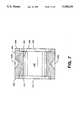
- FIG. 7illustrates a view taken along line 7--7 of FIG. 5;
- FIG. 14an alternative embodiment, illustrates a y-connector incorporating a compression seal and a swivel luer and catheter assembly
- FIG. 15illustrates a cross-sectional view of the y-connector of FIG. 4.
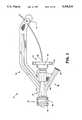
- FIG. 1illustrates a front view of a Y-connector 10, the present invention with major components including a body 12, a Touhy Borst adapter 14, a rotating connector 16, a side port 18, a side arm 20, a guidewire clamp 21, and a compression gasket 22, all of which are described later in detail.
- Each componentis made of medical grade polymer materials.
- the body 12is the main structure for the Y-connector 10, and is an injection molded polycarbonate material with two lumens 24 and 26 configured in a Y orientation.
- the straight through part of the Y containing lumen 24is used for insertion of a circular medical device and is connected to the Touhy Borst adapter 14.
- the branch of the Y with the lumen 26contains a female luer connector 28 that can be used for a number of functions including an additional device, injection of flushing medium such as saline, or injection of contrast medium such as Renographin®.
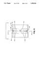
- FIG. 2illustrates a cross-sectional view of the Y-connector 10 where all numerals correspond to those elements previously described.
- Lumen 24aligns longitudinally along the ergonormally sculptured main body portion 38 of the body 12.
- a radiused shoulder 40 with an adjoining flat donut like annular surface 41, an annular snap ring 42 and a lesser radiused shoulder 44extend from the main body 38, and aligns concentrically along the longitudinal center line of the lumen 24 at the left end of the body 12.
- the quad O-ring and/or O-ring 36frictionally engages the lesser radiused shoulder 44.
- a radiused shoulder 46 with adjoining threads 48extends from the opposing end of the body 12 to align concentrically along the longitudinal center line of the lumen 24.
- a radiused cavity 50aligns concentrically with the lesser radiused lumen 24 at the right end of the body 12 and intersects a recessed seat 49.
- An annular lip 51extends outwardly to the right from the recessed seat 49 to accommodate and engage the compression gasket 22 as later described in detail.
- the flexible plastic compression gasket 22aligns in the radiused cavity 50 in alignment with the recessed seat 49.
- Protrusions 52a-52n at the mount of the cavity 50act as keepers to capture the compression gasket 22 in the cavity 50.
- Lumen 26aligns within the extension body 54, and intersects and connects with the lumen 24.
- a cavity 56aligns with the lumen 26 in conjunction with the female luer connector 28 which aligns concentrically with the lumen 26.
- Protrusions 52a-52nalign at the outer circumference of the cavity 50 to also capture a snap ring 55 on the end of the tubular extension of cap 30 to keep the thumb wheel knob loosely coupled to the body 12.
- the Touhy Borst adapter 14aligns to and threadingly engages the main body 12 and includes a thumb wheel knob 32 and pluralities of gripping ribs 58a-58n and 60a-60n.
- An index tab or rib 61is included on the thumb wheel knob 32 of the cap 30.
- the cap 30includes internal threads 62 which align and mate with the threads 48 of the body 12.
- An annular cavity 64aligns concentrically along the center line of the cap 30 and is bounded by the internal threads 62 and by a concentric tubular extension 66.
- the tubular extension 66extends to the left from the thumb wheel knob 32, and includes a passage hole 68 with a flared opening 70.
- An annular lip 72extends from the tubular extension 66 to engage and accommodate the compression gasket 22.
- the rotating connector 16includes a round main body 73 with a plurality of external gripping ribs 74a-74n around its outer circumference.
- a male luer 76extends longitudinally from the main body 73 through a cavity 78.
- Raised threads 80line the cavity 78.
- the cavity 78, raised threads 80, a ramped cylinder section or male section 82, and surrounding main body 73form the male luer 76.
- the passageway 84 formed by the ramped cylinder section 82aligns concentrically with radiused cavities 86 and 88 and also with a rounded annular groove 90 which is located off-center to the right of the cavity 88.
- Cavity 88includes a flat donut like annular surface 92 adjacent to the radiused portion of the cavity 88.
- FIG. 4illustrates a perspective view of the compression gasket 22, which can be made of silicon rubber or any other suitable material, compressible material which has a memory to return to its original geometrical shape when not compressed. Any other suitable materials can be utilized which exhibit compressible qualities and also exhibit memory to return to an original geometrical shape.
- the compression gasket 22includes a right edge 100 and a corresponding and opposed left edge 102.
- the outer circumferential wall 104is shaped in an hour glass configuration. The particular geometrical configuration of the outer circumferential wall 104 is that as illustrated in the Figure, but it is within the teachings of the present invention to vary the geometrical configuration as to the exact hour glass configuration.
- FIG. 5illustrates a side view of FIG. 4 where all numerals correspond to those elements previously described.
- Angled walls 114a and 16balign between the ribs 112a and 112d and the outer circumferential wall 104 as illustrated.
- Angled walls 114c-114d, 114e-114f and 114g-114halign between the ribs 112a-112d and about the circumferential wall 104 in a similar fashion.
- FIG. 6illustrates a sectional view taken along line 6--6 of FIG. 5 where all numerals correspond to those elements previously described.
- angled walls 114a-114b and corresponding unillustrated angled walls 114c-114d, 114e-114f and 114g-114hfold inwardly towards their like mirror surfaces to aid in full inward movement of the inner circumference to cause sealing of the guidewire 93.
- a sufficient fluid sealis maintained while still maintaining the ability of the guidewire 93 to slide to and fro in sliding engagement.
- FIG. 11illustrates an exploded view of the guidewire clamp 21 which snappingly affixes a guidewire to the side arm support 20 as illustrated in FIG. 1 where all numerals correspond to those elements previously described.
- the guidewire clamp 21includes a left clamp member 120, each of which mutually engage each other. Flexible plastic discs 124 and 126 align over and about the left and right clamp members 120 and 122.
- a multi-radius cylindrical shaft member 128extends perpendicularly from a disc shaped head 130 and includes a centrally located wide recessed groove 132. Edges 128a and 128b are rounded or can be ramped to transition between the general large radius of the shaft 128 down to the wide groove 132.
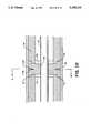
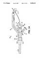
- FIG. 13illustrates the mode of operation of the guidewire 93 or medical device frictionally engaged and secured between the side arm 20 and the flexible plastic disc 126 and adjacent disc shaped head 136 where the entire guidewire clamp 21 has been forcibly positioned to the left to effect the securement of the guidewire to the side arm 20.
- the hole 144disengages from alignment with the wide groove 132 of the shaft 128 by action of the ramp 128b against the beveled edges of the hole 144 to cause the wider radius portion of the cylindrical shaft member 128 to firmly engage the hole 144 for positive securement of the guidewire clamp 21 and guidewire with respect to the side arm 20.
Landscapes
- Health & Medical Sciences (AREA)
- Heart & Thoracic Surgery (AREA)
- Pulmonology (AREA)
- Engineering & Computer Science (AREA)
- Anesthesiology (AREA)
- Biomedical Technology (AREA)
- Hematology (AREA)
- Life Sciences & Earth Sciences (AREA)
- Animal Behavior & Ethology (AREA)
- General Health & Medical Sciences (AREA)
- Public Health (AREA)
- Veterinary Medicine (AREA)
- Infusion, Injection, And Reservoir Apparatuses (AREA)
Abstract
Description
Claims (4)
Priority Applications (2)
| Application Number | Priority Date | Filing Date | Title |
|---|---|---|---|
| US07/869,340US5338314A (en) | 1991-04-22 | 1992-04-16 | Rotating Y-connector |
| EP93302968AEP0566426A1 (en) | 1992-04-16 | 1993-04-16 | Rotating Y-connector |
Applications Claiming Priority (2)
| Application Number | Priority Date | Filing Date | Title |
|---|---|---|---|
| US07/688,176US5205831A (en) | 1991-04-22 | 1991-04-22 | Compression gasket for y-connector |
| US07/869,340US5338314A (en) | 1991-04-22 | 1992-04-16 | Rotating Y-connector |
Related Parent Applications (1)
| Application Number | Title | Priority Date | Filing Date |
|---|---|---|---|
| US07/688,176Continuation-In-PartUS5205831A (en) | 1991-04-22 | 1991-04-22 | Compression gasket for y-connector |
Publications (1)
| Publication Number | Publication Date |
|---|---|
| US5338314Atrue US5338314A (en) | 1994-08-16 |
Family
ID=25353368
Family Applications (1)
| Application Number | Title | Priority Date | Filing Date |
|---|---|---|---|
| US07/869,340Expired - LifetimeUS5338314A (en) | 1991-04-22 | 1992-04-16 | Rotating Y-connector |
Country Status (2)
| Country | Link |
|---|---|
| US (1) | US5338314A (en) |
| EP (1) | EP0566426A1 (en) |
Cited By (57)
| Publication number | Priority date | Publication date | Assignee | Title |
|---|---|---|---|---|
| US5456676A (en)* | 1994-02-18 | 1995-10-10 | Merit Medical Systems, Inc. | Rotatable bubble-free connector |
| US5476454A (en)* | 1992-02-11 | 1995-12-19 | Minntech Corporation | Balloon catheter lock adaptor for use with a resterilization system |
| WO1996040347A1 (en)* | 1995-06-07 | 1996-12-19 | Heartport, Inc. | Endovascular system for arresting the heart |
| US5935112A (en)* | 1997-10-15 | 1999-08-10 | Stevens; Brian W. | Hemostasis valve with catheter/guidewire seals |
| US5989240A (en)* | 1998-02-27 | 1999-11-23 | Becton, Dickson And Company | Adaptor for mounting a fluid handling device on a catheter tubing |
| WO2000012160A1 (en)* | 1998-08-28 | 2000-03-09 | Mdc Investment Holdings, Inc. | Fluid infusion device with retractable needle |
| WO2000048663A1 (en)* | 1999-02-17 | 2000-08-24 | Becton, Dickinson And Company | Needleless injection site and guidewire assembly |
| US6331176B1 (en)* | 1999-03-11 | 2001-12-18 | Advanced Cardiovascular Systems, Inc. | Bleed back control assembly and method |
| US20020120231A1 (en)* | 2000-01-18 | 2002-08-29 | Douglas Joel S. | Subcutaneous injection set with secondary injection septum |
| WO2002047742A3 (en)* | 2000-12-15 | 2003-08-21 | Alsius Corp | Temperature sensor adapter for foley catheters |
| US6613014B1 (en)* | 2000-06-09 | 2003-09-02 | Advanced Cardiovascular Systems, Inc. | Catheter hub with detachable push device |
| US20030216771A1 (en)* | 2002-03-15 | 2003-11-20 | Thomas P. Osypka | Locking vascular introducer assembly with adjustable hemostatic seal |
| US6652509B1 (en) | 2000-04-03 | 2003-11-25 | Abbott Laboratories | Housing capable of connecting a container to a medical device |
| WO2002041940A3 (en)* | 2000-11-27 | 2003-12-31 | Kimberly Clark Co | A clamping assembly for maintaining the position of a respiratory care treatment device |
| US6685674B2 (en) | 2001-03-04 | 2004-02-03 | Sterling Medivations, Inc. | Infusion hub assembly and fluid line disconnect system |
| US6749589B1 (en) | 2000-01-18 | 2004-06-15 | Sterling Medications, Inc. | Subcutaneous injection set for use with a reservoir that has a septum |
| US20040172008A1 (en)* | 2002-11-19 | 2004-09-02 | Gmp/Cardiac Care, Inc. | Hemostasis valve and method of using a hemostasis valve |
| US20040181192A1 (en)* | 2003-03-11 | 2004-09-16 | Cuppy Michael John | Vascular access device and method of using same |
| US20040243054A1 (en)* | 2001-05-14 | 2004-12-02 | Kraushaar Timothy Y. | IV administration set identification system |
| US20040260309A1 (en)* | 2003-04-04 | 2004-12-23 | Packard Brian M. | Introduction apparatus |
| WO2005018732A1 (en)* | 2003-08-26 | 2005-03-03 | Zerusa Limited | A haemostasis device |
| US20050090835A1 (en)* | 2003-07-31 | 2005-04-28 | Deal Stephen E. | Wire guide holder |
| US20050119637A1 (en)* | 2002-04-08 | 2005-06-02 | Dan Lundgren | Transcutaneous portal device |
| US20050137576A1 (en)* | 2003-04-04 | 2005-06-23 | Packard Brian M. | Guide catheter and method of making same |
| US6921391B1 (en) | 1998-08-28 | 2005-07-26 | Mdc Investment Holdings, Inc. | Fluid infusion device with retractable needle |
| US20050235996A1 (en)* | 2004-04-27 | 2005-10-27 | Hooser David Theron V | Clamping assembly for limiting the depth of insertion of a respiratory care treatment device |
| US20050267404A1 (en)* | 2001-05-14 | 2005-12-01 | Kraushaar Timothy Y | IV administration set identification system |
| US20060195117A1 (en)* | 2003-07-31 | 2006-08-31 | Rucker Brian K | Wire guide holder with wire guide deflector |
| US20060211990A1 (en)* | 2003-11-18 | 2006-09-21 | Fangrow Thomas F Jr | Infusion set |
| US20060276772A1 (en)* | 2005-06-06 | 2006-12-07 | Sherwood Services Ag | Bayonet release of safety shield for needle tip |
| US20070010796A1 (en)* | 2005-06-23 | 2007-01-11 | Derek Moran | Catheter device |
| US20070185454A1 (en)* | 2006-02-07 | 2007-08-09 | Fangrow Thomas F Jr | Infusion set |
| US20070238928A1 (en)* | 2006-04-07 | 2007-10-11 | Boston Scientific Scimed, Inc. | Biopsy port for easy device passage |
| US7520489B2 (en) | 2003-06-17 | 2009-04-21 | Filtertek Inc. | Fluid handling device and method of making same |
| US20090171153A1 (en)* | 2007-12-27 | 2009-07-02 | Tyco Healthcare Group Lp | Insertion assisting tool for an endoscope |
| US20090264864A1 (en)* | 2008-04-21 | 2009-10-22 | Paul S. Teirstein | Guide wire retention and positioning apparatus |
| US7654735B2 (en) | 2005-11-03 | 2010-02-02 | Covidien Ag | Electronic thermometer |
| US7731692B2 (en) | 2005-07-11 | 2010-06-08 | Covidien Ag | Device for shielding a sharp tip of a cannula and method of using the same |
| US20100145313A1 (en)* | 2003-04-04 | 2010-06-10 | Packard Brian M | System and method for treating septal defects |
| US7828773B2 (en) | 2005-07-11 | 2010-11-09 | Covidien Ag | Safety reset key and needle assembly |
| US7850650B2 (en) | 2005-07-11 | 2010-12-14 | Covidien Ag | Needle safety shield with reset |
| US7905857B2 (en) | 2005-07-11 | 2011-03-15 | Covidien Ag | Needle assembly including obturator with safety reset |
| US8357104B2 (en) | 2007-11-01 | 2013-01-22 | Coviden Lp | Active stylet safety shield |
| US8652104B2 (en) | 2010-06-25 | 2014-02-18 | Smiths Medical Asd, Inc. | Catheter assembly with seal member |
| US8834417B2 (en) | 2005-06-06 | 2014-09-16 | Covidien Ag | Needle assembly with removable depth stop |
| US20150190610A1 (en)* | 2014-01-06 | 2015-07-09 | Biosense Webster (Israel) Ltd. | Cable arranger |
| US9345859B2 (en) | 2012-09-06 | 2016-05-24 | Corindus, Inc. | Hemostasis valve and system for guide catheter control |
| US9504806B2 (en)* | 2012-10-02 | 2016-11-29 | The Queen's Medical Center | Vascular access systems having a guidewire anti-migration feature |
| US9545495B2 (en) | 2010-06-25 | 2017-01-17 | Smiths Medical Asd, Inc. | Catheter assembly with seal member |
| US10361802B1 (en) | 1999-02-01 | 2019-07-23 | Blanding Hovenweep, Llc | Adaptive pattern recognition based control system and method |
| US10549071B2 (en) | 2013-10-15 | 2020-02-04 | Corindus, Inc. | Guide catheter control flexible track |
| WO2020111003A1 (en)* | 2018-11-27 | 2020-06-04 | テルモ株式会社 | Medical elongated body and puncture needle assembly |
| CN112023266A (en)* | 2020-07-30 | 2020-12-04 | 创领心律管理医疗器械(上海)有限公司 | Torsion Aid |
| WO2023278359A1 (en)* | 2021-07-02 | 2023-01-05 | Becton, Dickinson And Company | Catheter assembly adapter, instrument delivery device, and related methods |
| US11617858B2 (en) | 2019-01-18 | 2023-04-04 | Ipg Photonics Corporation | Ergonomic steering handle |
| WO2023225139A1 (en)* | 2022-05-19 | 2023-11-23 | Becton, Dickinson And Company | Vascular access device with extendable catheter |
| US11994375B2 (en) | 2015-06-30 | 2024-05-28 | Corindus, Inc. | System and method for detecting a position of a guide catheter support |
Families Citing this family (5)
| Publication number | Priority date | Publication date | Assignee | Title |
|---|---|---|---|---|
| EP2793991B1 (en) | 2011-12-22 | 2019-02-06 | Boston Scientific Scimed, Inc. | Steerable sheath handle pulley mechanism |
| EP2842590A1 (en)* | 2013-09-03 | 2015-03-04 | Coloplast A/S | Access sheath |
| EP4018946A1 (en) | 2017-05-03 | 2022-06-29 | Medtronic Vascular, Inc. | Tissue-removing catheter |
| US11690645B2 (en) | 2017-05-03 | 2023-07-04 | Medtronic Vascular, Inc. | Tissue-removing catheter |
| US11819236B2 (en) | 2019-05-17 | 2023-11-21 | Medtronic Vascular, Inc. | Tissue-removing catheter |
Citations (17)
| Publication number | Priority date | Publication date | Assignee | Title |
|---|---|---|---|---|
| GB2063679A (en)* | 1979-11-29 | 1981-06-10 | Abbott Lab | Venipuncture device |
| US4419094A (en)* | 1981-06-08 | 1983-12-06 | The Kendall Company | Suprapubic catheter system |
| US4475548A (en)* | 1982-06-01 | 1984-10-09 | Rudolph Muto | Fitting for endotracheal tube apparatus and method of making the fitting |
| US4723550A (en)* | 1986-11-10 | 1988-02-09 | Cordis Corporation | Leakproof hemostasis valve with single valve member |
| US4809679A (en)* | 1986-11-19 | 1989-03-07 | Olympus Optical Co., Ltd. | Forceps plug for endoscopes |
| US4817637A (en)* | 1987-11-25 | 1989-04-04 | Medical Engineering Corporation | Subcutaneous injection and withdrawal site |
| US4857062A (en)* | 1988-03-09 | 1989-08-15 | Medical Parameters, Inc. | Catheter introducer valve |
| US4895346A (en)* | 1988-05-02 | 1990-01-23 | The Kendall Company | Valve assembly |
| US4929235A (en)* | 1985-07-31 | 1990-05-29 | Universal Medical Instrument Corp. | Self-sealing percutaneous tube introducer |
| US4932633A (en)* | 1988-11-21 | 1990-06-12 | Schneider-Shiley (U.S.A.) Inc. | Hemostasis valve |
| US4978341A (en)* | 1988-04-07 | 1990-12-18 | Schneider Europe | Introducer valve for a catheter arrangement |
| US5009391A (en)* | 1988-05-02 | 1991-04-23 | The Kendall Company | Valve assembly |
| US5045061A (en)* | 1990-02-02 | 1991-09-03 | C. R. Bard, Inc. | Balloon catheter and locking guidewire system |
| US5088984A (en)* | 1990-10-03 | 1992-02-18 | Tri-State Hospital Supply Corporation | Medical connector |
| US5092857A (en)* | 1991-05-17 | 1992-03-03 | Fleischhacker John J | Hemostasis valve having support shoulders |
| US5129887A (en)* | 1988-12-07 | 1992-07-14 | Scimed Life Systems, Inc. | Adjustable manifold for dilatation catheter |
| US5158553A (en)* | 1990-12-26 | 1992-10-27 | Cardiopulmonics | Rotatably actuated constricting catheter valve |
Family Cites Families (4)
| Publication number | Priority date | Publication date | Assignee | Title |
|---|---|---|---|---|
| DE8619671U1 (en)* | 1986-07-22 | 1989-03-09 | Sterimed Gesellschaft für medizinischen Bedarf mbH, 6600 Saarbrücken | Coupling for connecting a medical tube, in particular a drain or a catheter, to another device |
| DE3834600C1 (en)* | 1988-10-11 | 1989-12-21 | B. Braun Melsungen Ag, 3508 Melsungen, De | Puncturing and introduction device for elongate articles |
| US5062648A (en)* | 1989-09-26 | 1991-11-05 | Interventional Technologies, Inc. | Seal for rotating torque tube with seal valve |
| US5205831A (en)* | 1991-04-22 | 1993-04-27 | Burron Medical, Inc. | Compression gasket for y-connector |
- 1992
- 1992-04-16USUS07/869,340patent/US5338314A/ennot_activeExpired - Lifetime
- 1993
- 1993-04-16EPEP93302968Apatent/EP0566426A1/ennot_activeWithdrawn
Patent Citations (18)
| Publication number | Priority date | Publication date | Assignee | Title |
|---|---|---|---|---|
| US4496348A (en)* | 1979-11-29 | 1985-01-29 | Abbott Laboratories | Venipuncture device |
| GB2063679A (en)* | 1979-11-29 | 1981-06-10 | Abbott Lab | Venipuncture device |
| US4419094A (en)* | 1981-06-08 | 1983-12-06 | The Kendall Company | Suprapubic catheter system |
| US4475548A (en)* | 1982-06-01 | 1984-10-09 | Rudolph Muto | Fitting for endotracheal tube apparatus and method of making the fitting |
| US4929235A (en)* | 1985-07-31 | 1990-05-29 | Universal Medical Instrument Corp. | Self-sealing percutaneous tube introducer |
| US4723550A (en)* | 1986-11-10 | 1988-02-09 | Cordis Corporation | Leakproof hemostasis valve with single valve member |
| US4809679A (en)* | 1986-11-19 | 1989-03-07 | Olympus Optical Co., Ltd. | Forceps plug for endoscopes |
| US4817637A (en)* | 1987-11-25 | 1989-04-04 | Medical Engineering Corporation | Subcutaneous injection and withdrawal site |
| US4857062A (en)* | 1988-03-09 | 1989-08-15 | Medical Parameters, Inc. | Catheter introducer valve |
| US4978341A (en)* | 1988-04-07 | 1990-12-18 | Schneider Europe | Introducer valve for a catheter arrangement |
| US4895346A (en)* | 1988-05-02 | 1990-01-23 | The Kendall Company | Valve assembly |
| US5009391A (en)* | 1988-05-02 | 1991-04-23 | The Kendall Company | Valve assembly |
| US4932633A (en)* | 1988-11-21 | 1990-06-12 | Schneider-Shiley (U.S.A.) Inc. | Hemostasis valve |
| US5129887A (en)* | 1988-12-07 | 1992-07-14 | Scimed Life Systems, Inc. | Adjustable manifold for dilatation catheter |
| US5045061A (en)* | 1990-02-02 | 1991-09-03 | C. R. Bard, Inc. | Balloon catheter and locking guidewire system |
| US5088984A (en)* | 1990-10-03 | 1992-02-18 | Tri-State Hospital Supply Corporation | Medical connector |
| US5158553A (en)* | 1990-12-26 | 1992-10-27 | Cardiopulmonics | Rotatably actuated constricting catheter valve |
| US5092857A (en)* | 1991-05-17 | 1992-03-03 | Fleischhacker John J | Hemostasis valve having support shoulders |
Cited By (117)
| Publication number | Priority date | Publication date | Assignee | Title |
|---|---|---|---|---|
| US5766151A (en)* | 1991-07-16 | 1998-06-16 | Heartport, Inc. | Endovascular system for arresting the heart |
| US5814016A (en)* | 1991-07-16 | 1998-09-29 | Heartport, Inc. | Endovascular system for arresting the heart |
| US6913600B2 (en) | 1991-07-16 | 2005-07-05 | Heartport, Inc. | Endovascular system for arresting the heart |
| US5476454A (en)* | 1992-02-11 | 1995-12-19 | Minntech Corporation | Balloon catheter lock adaptor for use with a resterilization system |
| US5456676A (en)* | 1994-02-18 | 1995-10-10 | Merit Medical Systems, Inc. | Rotatable bubble-free connector |
| WO1996040347A1 (en)* | 1995-06-07 | 1996-12-19 | Heartport, Inc. | Endovascular system for arresting the heart |
| US5935112A (en)* | 1997-10-15 | 1999-08-10 | Stevens; Brian W. | Hemostasis valve with catheter/guidewire seals |
| US5989240A (en)* | 1998-02-27 | 1999-11-23 | Becton, Dickson And Company | Adaptor for mounting a fluid handling device on a catheter tubing |
| US6921391B1 (en) | 1998-08-28 | 2005-07-26 | Mdc Investment Holdings, Inc. | Fluid infusion device with retractable needle |
| AU743918B2 (en)* | 1998-08-28 | 2002-02-07 | Mdc Investment Holdings, Inc. | Fluid infusion device with retractable needle |
| WO2000012160A1 (en)* | 1998-08-28 | 2000-03-09 | Mdc Investment Holdings, Inc. | Fluid infusion device with retractable needle |
| US10361802B1 (en) | 1999-02-01 | 2019-07-23 | Blanding Hovenweep, Llc | Adaptive pattern recognition based control system and method |
| WO2000048663A1 (en)* | 1999-02-17 | 2000-08-24 | Becton, Dickinson And Company | Needleless injection site and guidewire assembly |
| US6331176B1 (en)* | 1999-03-11 | 2001-12-18 | Advanced Cardiovascular Systems, Inc. | Bleed back control assembly and method |
| US6695820B1 (en) | 1999-03-11 | 2004-02-24 | Advanced Cardiovascular Systems, Inc. | Bleed back control assembly |
| US6749589B1 (en) | 2000-01-18 | 2004-06-15 | Sterling Medications, Inc. | Subcutaneous injection set for use with a reservoir that has a septum |
| US20020120231A1 (en)* | 2000-01-18 | 2002-08-29 | Douglas Joel S. | Subcutaneous injection set with secondary injection septum |
| US20040143241A1 (en)* | 2000-01-18 | 2004-07-22 | Joel Douglas | Subcutaneous injection set for use with a reservoir that has a septum |
| US6652509B1 (en) | 2000-04-03 | 2003-11-25 | Abbott Laboratories | Housing capable of connecting a container to a medical device |
| US6613014B1 (en)* | 2000-06-09 | 2003-09-02 | Advanced Cardiovascular Systems, Inc. | Catheter hub with detachable push device |
| WO2002041940A3 (en)* | 2000-11-27 | 2003-12-31 | Kimberly Clark Co | A clamping assembly for maintaining the position of a respiratory care treatment device |
| US6688306B1 (en) | 2000-11-27 | 2004-02-10 | Kimberly-Clark Worldwide, Inc. | Clamping assembly for maintaining the position of a respiratory care treatment device |
| WO2002047742A3 (en)* | 2000-12-15 | 2003-08-21 | Alsius Corp | Temperature sensor adapter for foley catheters |
| WO2002068014A3 (en)* | 2001-02-26 | 2002-10-31 | Sterling Medivations Inc | Subcutaneous injection set with secondary injection septum |
| US6685674B2 (en) | 2001-03-04 | 2004-02-03 | Sterling Medivations, Inc. | Infusion hub assembly and fluid line disconnect system |
| US20040138620A1 (en)* | 2001-03-04 | 2004-07-15 | Douglas Joel S. | Infusion hub assembly and fluid line disconnect system |
| US8152769B2 (en) | 2001-03-04 | 2012-04-10 | Tecpharma Licensing Ag | Infusion hub assembly and fluid line disconnect system |
| US7744568B2 (en) | 2001-03-04 | 2010-06-29 | Icu Medical, Inc. | Infusion hub assembly and fluid line disconnect system |
| US20100268166A1 (en)* | 2001-03-04 | 2010-10-21 | Icu Medical, Inc. | Infusion hub assembly and fluid line disconnect system |
| US20080312598A1 (en)* | 2001-03-04 | 2008-12-18 | Sterling Medivations, Inc. | Infusion hub assembly and fluid line disconnect system |
| US7455662B2 (en)* | 2001-05-14 | 2008-11-25 | Kraushaar Timothy Y | IV administration set identification system |
| US20050267404A1 (en)* | 2001-05-14 | 2005-12-01 | Kraushaar Timothy Y | IV administration set identification system |
| US7338476B2 (en) | 2001-05-14 | 2008-03-04 | Kraushaar Timothy Y | IV administration set identification system |
| US20040243054A1 (en)* | 2001-05-14 | 2004-12-02 | Kraushaar Timothy Y. | IV administration set identification system |
| US7192433B2 (en)* | 2002-03-15 | 2007-03-20 | Oscor Inc. | Locking vascular introducer assembly with adjustable hemostatic seal |
| US20030216771A1 (en)* | 2002-03-15 | 2003-11-20 | Thomas P. Osypka | Locking vascular introducer assembly with adjustable hemostatic seal |
| US20050119637A1 (en)* | 2002-04-08 | 2005-06-02 | Dan Lundgren | Transcutaneous portal device |
| US7172574B2 (en)* | 2002-04-08 | 2007-02-06 | Transcutan Ab | Transcutaneous portal device |
| US20040172008A1 (en)* | 2002-11-19 | 2004-09-02 | Gmp/Cardiac Care, Inc. | Hemostasis valve and method of using a hemostasis valve |
| US20040181192A1 (en)* | 2003-03-11 | 2004-09-16 | Cuppy Michael John | Vascular access device and method of using same |
| US20100145313A1 (en)* | 2003-04-04 | 2010-06-10 | Packard Brian M | System and method for treating septal defects |
| US20100030193A1 (en)* | 2003-04-04 | 2010-02-04 | Minnesota Medtec, Inc. | Guide catheter and method of making same |
| US20050137576A1 (en)* | 2003-04-04 | 2005-06-23 | Packard Brian M. | Guide catheter and method of making same |
| US20040260309A1 (en)* | 2003-04-04 | 2004-12-23 | Packard Brian M. | Introduction apparatus |
| US8038123B2 (en) | 2003-06-17 | 2011-10-18 | Filtertek Inc. | Fluid handling device and method of making same |
| US7520489B2 (en) | 2003-06-17 | 2009-04-21 | Filtertek Inc. | Fluid handling device and method of making same |
| US20060195117A1 (en)* | 2003-07-31 | 2006-08-31 | Rucker Brian K | Wire guide holder with wire guide deflector |
| US7637863B2 (en) | 2003-07-31 | 2009-12-29 | Wilson-Cook Medical Inc. | Wire guide holder |
| US20050090835A1 (en)* | 2003-07-31 | 2005-04-28 | Deal Stephen E. | Wire guide holder |
| US7976503B2 (en) | 2003-08-26 | 2011-07-12 | Vascular Solutions Zerusa Limited | Haemostasis device |
| US20050085789A1 (en)* | 2003-08-26 | 2005-04-21 | Khan Mazhar M. | Haemostasis device |
| WO2005018732A1 (en)* | 2003-08-26 | 2005-03-03 | Zerusa Limited | A haemostasis device |
| US7314463B2 (en) | 2003-11-18 | 2008-01-01 | Icu Medical, Inc. | Infusion set |
| US20060211990A1 (en)* | 2003-11-18 | 2006-09-21 | Fangrow Thomas F Jr | Infusion set |
| US7300419B2 (en) | 2003-11-18 | 2007-11-27 | Icu Medical, Inc. | Infusion set |
| US7309326B2 (en) | 2003-11-18 | 2007-12-18 | Icu Medical, Inc. | Infusion set |
| US7311694B2 (en) | 2003-11-18 | 2007-12-25 | Icu Medical, Inc. | Infusion set |
| US7744570B2 (en) | 2003-11-18 | 2010-06-29 | Icu Medical, Inc. | Infusion set |
| US7331939B2 (en) | 2003-11-18 | 2008-02-19 | Icu Medical, Inc. | Infusion set |
| US20060270990A1 (en)* | 2003-11-18 | 2006-11-30 | Fangrow Thomas F Jr | Infusion set |
| US20060276760A1 (en)* | 2003-11-18 | 2006-12-07 | Fangrow Thomas F Jr | Infusion set |
| US7407491B2 (en) | 2003-11-18 | 2008-08-05 | Icu Medical, Inc. | Infusion set |
| US7297138B2 (en) | 2003-11-18 | 2007-11-20 | Icu Medical, Inc. | Infusion set |
| US20060270992A1 (en)* | 2003-11-18 | 2006-11-30 | Fangrow Thomas F Jr | Infusion set |
| US20060224119A1 (en)* | 2003-11-18 | 2006-10-05 | Fangrow Thomas F Jr | Infusion set |
| US20060211991A1 (en)* | 2003-11-18 | 2006-09-21 | Fangrow Thomas F Jr | Infusion set |
| US7353822B2 (en) | 2004-04-27 | 2008-04-08 | Kimberly-Clark , Worldwide, Inc. | Clamping assembly for limiting the depth of insertion of a respiratory care treatment device |
| US20050235996A1 (en)* | 2004-04-27 | 2005-10-27 | Hooser David Theron V | Clamping assembly for limiting the depth of insertion of a respiratory care treatment device |
| WO2006014320A3 (en)* | 2004-07-02 | 2007-03-22 | Timothy Y Kraushaar | Iv administration set identification system |
| US8834417B2 (en) | 2005-06-06 | 2014-09-16 | Covidien Ag | Needle assembly with removable depth stop |
| US20060276772A1 (en)* | 2005-06-06 | 2006-12-07 | Sherwood Services Ag | Bayonet release of safety shield for needle tip |
| US20070010796A1 (en)* | 2005-06-23 | 2007-01-11 | Derek Moran | Catheter device |
| US7914519B2 (en) | 2005-06-23 | 2011-03-29 | Elcam Medical Agricultural Cooperative Association, Ltd. | Catheter device |
| US8162889B2 (en) | 2005-07-11 | 2012-04-24 | Covidien Ag | Safety reset key and needle assembly |
| US7976498B2 (en) | 2005-07-11 | 2011-07-12 | Tyco Healthcare Group Lp | Needle assembly including obturator with safety reset |
| US7828773B2 (en) | 2005-07-11 | 2010-11-09 | Covidien Ag | Safety reset key and needle assembly |
| US7850650B2 (en) | 2005-07-11 | 2010-12-14 | Covidien Ag | Needle safety shield with reset |
| US8523809B2 (en) | 2005-07-11 | 2013-09-03 | Covidien Ag | Device for shielding a sharp tip of a cannula and method of using the same |
| US7905857B2 (en) | 2005-07-11 | 2011-03-15 | Covidien Ag | Needle assembly including obturator with safety reset |
| US7731692B2 (en) | 2005-07-11 | 2010-06-08 | Covidien Ag | Device for shielding a sharp tip of a cannula and method of using the same |
| US8419687B2 (en) | 2005-07-11 | 2013-04-16 | Covidien Ag | Device for shielding a sharp tip of a cannula and method of using the same |
| US8348894B2 (en) | 2005-07-11 | 2013-01-08 | Covidien Lp | Needle assembly including obturator with safety reset |
| US7654735B2 (en) | 2005-11-03 | 2010-02-02 | Covidien Ag | Electronic thermometer |
| US20070185454A1 (en)* | 2006-02-07 | 2007-08-09 | Fangrow Thomas F Jr | Infusion set |
| US20070185455A1 (en)* | 2006-02-07 | 2007-08-09 | Fangrow Thomas F Jr | Infusion set |
| US7931615B2 (en) | 2006-02-07 | 2011-04-26 | Icu Medical, Inc. | Infusion set |
| US7892216B2 (en) | 2006-02-07 | 2011-02-22 | Icu Medical, Inc. | Infusion set |
| US8657788B2 (en) | 2006-02-07 | 2014-02-25 | Tecpharma Licensing Ag | Infusion set |
| US20070185441A1 (en)* | 2006-02-07 | 2007-08-09 | Fangrow Thomas F Jr | Infusion set |
| US8956330B2 (en) | 2006-02-07 | 2015-02-17 | Techpharma Licensing Ag | Infusion set |
| US20070238928A1 (en)* | 2006-04-07 | 2007-10-11 | Boston Scientific Scimed, Inc. | Biopsy port for easy device passage |
| US8357104B2 (en) | 2007-11-01 | 2013-01-22 | Coviden Lp | Active stylet safety shield |
| US20090171153A1 (en)* | 2007-12-27 | 2009-07-02 | Tyco Healthcare Group Lp | Insertion assisting tool for an endoscope |
| US20090264864A1 (en)* | 2008-04-21 | 2009-10-22 | Paul S. Teirstein | Guide wire retention and positioning apparatus |
| US8652104B2 (en) | 2010-06-25 | 2014-02-18 | Smiths Medical Asd, Inc. | Catheter assembly with seal member |
| US9399116B2 (en) | 2010-06-25 | 2016-07-26 | Smiths Medical Asd, Inc. | Method of making catheter assembly with seal member |
| US9545495B2 (en) | 2010-06-25 | 2017-01-17 | Smiths Medical Asd, Inc. | Catheter assembly with seal member |
| US10080867B2 (en) | 2010-06-25 | 2018-09-25 | Smiths Medical Asd, Inc. | Method of making catheter assembly with seal member |
| US11207495B2 (en) | 2010-06-25 | 2021-12-28 | Smiths Medical Asd, Inc. | Catheter assembly with seal member |
| US11413431B2 (en) | 2012-09-06 | 2022-08-16 | Corindus, Inc. | Hemostasis valve for guide catheter control |
| US9452277B2 (en) | 2012-09-06 | 2016-09-27 | Corindus, Inc. | Hemostasis valve for guide catheter control |
| US9345859B2 (en) | 2012-09-06 | 2016-05-24 | Corindus, Inc. | Hemostasis valve and system for guide catheter control |
| US10307570B2 (en) | 2012-09-06 | 2019-06-04 | Corindus, Inc. | Hemostasis valve for guide catheter control |
| US9504806B2 (en)* | 2012-10-02 | 2016-11-29 | The Queen's Medical Center | Vascular access systems having a guidewire anti-migration feature |
| US11964116B2 (en) | 2013-10-15 | 2024-04-23 | Corindus, Inc. | Guide catheter control flexible track |
| US11801366B2 (en) | 2013-10-15 | 2023-10-31 | Corindus, Inc. | Guide catheter control flexible track |
| US10549071B2 (en) | 2013-10-15 | 2020-02-04 | Corindus, Inc. | Guide catheter control flexible track |
| US11007348B2 (en) | 2013-10-15 | 2021-05-18 | Corindus, Inc. | Guide catheter control flexible track |
| US20150190610A1 (en)* | 2014-01-06 | 2015-07-09 | Biosense Webster (Israel) Ltd. | Cable arranger |
| US10588809B2 (en)* | 2014-01-06 | 2020-03-17 | Biosense Webster (Israel) Ltd. | Cable arranger |
| US11994375B2 (en) | 2015-06-30 | 2024-05-28 | Corindus, Inc. | System and method for detecting a position of a guide catheter support |
| JPWO2020111003A1 (en)* | 2018-11-27 | 2021-10-07 | テルモ株式会社 | Medical long body and puncture needle assembly |
| WO2020111003A1 (en)* | 2018-11-27 | 2020-06-04 | テルモ株式会社 | Medical elongated body and puncture needle assembly |
| US11617858B2 (en) | 2019-01-18 | 2023-04-04 | Ipg Photonics Corporation | Ergonomic steering handle |
| CN112023266A (en)* | 2020-07-30 | 2020-12-04 | 创领心律管理医疗器械(上海)有限公司 | Torsion Aid |
| WO2023278359A1 (en)* | 2021-07-02 | 2023-01-05 | Becton, Dickinson And Company | Catheter assembly adapter, instrument delivery device, and related methods |
| WO2023225139A1 (en)* | 2022-05-19 | 2023-11-23 | Becton, Dickinson And Company | Vascular access device with extendable catheter |
Also Published As
| Publication number | Publication date |
|---|---|
| EP0566426A1 (en) | 1993-10-20 |
Similar Documents
| Publication | Publication Date | Title |
|---|---|---|
| US5338314A (en) | Rotating Y-connector | |
| US5205831A (en) | Compression gasket for y-connector | |
| US5279597A (en) | Catheter compression clamp | |
| US4607868A (en) | Universal connector | |
| US4838269A (en) | Manifold for angioplasty balloon catheter | |
| US4676530A (en) | Coupling assembly for use in fluid flow systems | |
| US4526572A (en) | Medical connector | |
| US5944697A (en) | Percutaneous catheter introducer | |
| US6402723B1 (en) | Inline hemostasis valve | |
| EP0733380B1 (en) | Luer-type connector | |
| US5591137A (en) | Hemostasis valve with locking seal | |
| US4613329A (en) | Catheter placement device | |
| US5989223A (en) | Rotatable medical valve closure | |
| US4387879A (en) | Self-sealing connector for use with plastic cannulas and vessel catheters | |
| US5693025A (en) | Adapter with hemostasis valve and rotatable connector | |
| EP0513969B1 (en) | Hemostasis valve | |
| EP0900105B1 (en) | Hemostasis valve | |
| US5470522A (en) | Method of molding Y-adapter with a sideport radius | |
| EP0316096B1 (en) | Universal hemostasis cannula | |
| CA2001558A1 (en) | Hemostasis valve | |
| WO1998013083A1 (en) | Catheter sheath introducer with improved hemostasis valve | |
| EP0607343B1 (en) | Rotatable medical valve closure | |
| CA1202340A (en) | Swivel coupling | |
| US20230405295A1 (en) | Cathlock System for Proximally Trimmable Catheter | |
| CN220002547U (en) | Body seat of extracorporeal circulation intubation and extracorporeal circulation catheter intubation |
Legal Events
| Date | Code | Title | Description |
|---|---|---|---|
| AS | Assignment | Owner name:ANGEION CORPORATION, MINNESOTA Free format text:ASSIGNMENT OF ASSIGNORS INTEREST.;ASSIGNOR:RYAN, WILLIAM P.;REEL/FRAME:006097/0452 Effective date:19920327 | |
| AS | Assignment | Owner name:BURRON MEDICAL, INC., PENNSYLVANIA Free format text:ASSIGNMENT OF ASSIGNORS INTEREST.;ASSIGNOR:ANGEION CORPORATION;REEL/FRAME:006289/0604 Effective date:19920922 | |
| AS | Assignment | Owner name:B. BRAUN MEDICAL INC., PENNSYLVANIA Free format text:CHANGE OF NAME;ASSIGNOR:BURRON MEDICAL INC.;REEL/FRAME:006537/0448 Effective date:19921001 | |
| STCF | Information on status: patent grant | Free format text:PATENTED CASE | |
| FEPP | Fee payment procedure | Free format text:PAYOR NUMBER ASSIGNED (ORIGINAL EVENT CODE: ASPN); ENTITY STATUS OF PATENT OWNER: LARGE ENTITY | |
| FEPP | Fee payment procedure | Free format text:PAT HLDR NO LONGER CLAIMS SMALL ENT STAT AS SMALL BUSINESS (ORIGINAL EVENT CODE: LSM2); ENTITY STATUS OF PATENT OWNER: LARGE ENTITY | |
| FPAY | Fee payment | Year of fee payment:4 | |
| SULP | Surcharge for late payment | ||
| FPAY | Fee payment | Year of fee payment:8 | |
| FPAY | Fee payment | Year of fee payment:12 |