US5338210A - Media connector interface for use with a PCMCIA-architecture communications card - Google Patents
Media connector interface for use with a PCMCIA-architecture communications cardDownload PDFInfo
- Publication number
- US5338210A US5338210AUS08/040,656US4065693AUS5338210AUS 5338210 AUS5338210 AUS 5338210AUS 4065693 AUS4065693 AUS 4065693AUS 5338210 AUS5338210 AUS 5338210A
- Authority
- US
- United States
- Prior art keywords
- communications card
- media connector
- planar surface
- aperture
- access portion
- Prior art date
- Legal status (The legal status is an assumption and is not a legal conclusion. Google has not performed a legal analysis and makes no representation as to the accuracy of the status listed.)
- Expired - Lifetime
Links
Images


Classifications
- G—PHYSICS
- G06—COMPUTING OR CALCULATING; COUNTING
- G06F—ELECTRIC DIGITAL DATA PROCESSING
- G06F1/00—Details not covered by groups G06F3/00 - G06F13/00 and G06F21/00
- G06F1/16—Constructional details or arrangements
- G06F1/1613—Constructional details or arrangements for portable computers
- G06F1/1633—Constructional details or arrangements of portable computers not specific to the type of enclosures covered by groups G06F1/1615 - G06F1/1626
- G06F1/1656—Details related to functional adaptations of the enclosure, e.g. to provide protection against EMI, shock, water, or to host detachable peripherals like a mouse or removable expansions units like PCMCIA cards, or to provide access to internal components for maintenance or to removable storage supports like CDs or DVDs, or to mechanically mount accessories
- G—PHYSICS
- G06—COMPUTING OR CALCULATING; COUNTING
- G06F—ELECTRIC DIGITAL DATA PROCESSING
- G06F1/00—Details not covered by groups G06F3/00 - G06F13/00 and G06F21/00
- G06F1/16—Constructional details or arrangements
- G06F1/1613—Constructional details or arrangements for portable computers
- G—PHYSICS
- G06—COMPUTING OR CALCULATING; COUNTING
- G06F—ELECTRIC DIGITAL DATA PROCESSING
- G06F1/00—Details not covered by groups G06F3/00 - G06F13/00 and G06F21/00
- G06F1/16—Constructional details or arrangements
- G06F1/1613—Constructional details or arrangements for portable computers
- G06F1/1615—Constructional details or arrangements for portable computers with several enclosures having relative motions, each enclosure supporting at least one I/O or computing function
- G06F1/1616—Constructional details or arrangements for portable computers with several enclosures having relative motions, each enclosure supporting at least one I/O or computing function with folding flat displays, e.g. laptop computers or notebooks having a clamshell configuration, with body parts pivoting to an open position around an axis parallel to the plane they define in closed position
- G—PHYSICS
- G06—COMPUTING OR CALCULATING; COUNTING
- G06F—ELECTRIC DIGITAL DATA PROCESSING
- G06F1/00—Details not covered by groups G06F3/00 - G06F13/00 and G06F21/00
- G06F1/16—Constructional details or arrangements
- G06F1/1613—Constructional details or arrangements for portable computers
- G06F1/1632—External expansion units, e.g. docking stations
- H—ELECTRICITY
- H01—ELECTRIC ELEMENTS
- H01R—ELECTRICALLY-CONDUCTIVE CONNECTIONS; STRUCTURAL ASSOCIATIONS OF A PLURALITY OF MUTUALLY-INSULATED ELECTRICAL CONNECTING ELEMENTS; COUPLING DEVICES; CURRENT COLLECTORS
- H01R13/00—Details of coupling devices of the kinds covered by groups H01R12/70 or H01R24/00 - H01R33/00
- H01R13/62—Means for facilitating engagement or disengagement of coupling parts or for holding them in engagement
- H01R13/639—Additional means for holding or locking coupling parts together, after engagement, e.g. separate keylock, retainer strap
- H—ELECTRICITY
- H01—ELECTRIC ELEMENTS
- H01R—ELECTRICALLY-CONDUCTIVE CONNECTIONS; STRUCTURAL ASSOCIATIONS OF A PLURALITY OF MUTUALLY-INSULATED ELECTRICAL CONNECTING ELEMENTS; COUPLING DEVICES; CURRENT COLLECTORS
- H01R31/00—Coupling parts supported only by co-operation with counterpart
- H01R31/06—Intermediate parts for linking two coupling parts, e.g. adapter
- H—ELECTRICITY
- H01—ELECTRIC ELEMENTS
- H01R—ELECTRICALLY-CONDUCTIVE CONNECTIONS; STRUCTURAL ASSOCIATIONS OF A PLURALITY OF MUTUALLY-INSULATED ELECTRICAL CONNECTING ELEMENTS; COUPLING DEVICES; CURRENT COLLECTORS
- H01R2201/00—Connectors or connections adapted for particular applications
- H01R2201/06—Connectors or connections adapted for particular applications for computer periphery
- H—ELECTRICITY
- H01—ELECTRIC ELEMENTS
- H01R—ELECTRICALLY-CONDUCTIVE CONNECTIONS; STRUCTURAL ASSOCIATIONS OF A PLURALITY OF MUTUALLY-INSULATED ELECTRICAL CONNECTING ELEMENTS; COUPLING DEVICES; CURRENT COLLECTORS
- H01R2201/00—Connectors or connections adapted for particular applications
- H01R2201/16—Connectors or connections adapted for particular applications for telephony
- H—ELECTRICITY
- H01—ELECTRIC ELEMENTS
- H01R—ELECTRICALLY-CONDUCTIVE CONNECTIONS; STRUCTURAL ASSOCIATIONS OF A PLURALITY OF MUTUALLY-INSULATED ELECTRICAL CONNECTING ELEMENTS; COUPLING DEVICES; CURRENT COLLECTORS
- H01R24/00—Two-part coupling devices, or either of their cooperating parts, characterised by their overall structure
- H01R24/60—Contacts spaced along planar side wall transverse to longitudinal axis of engagement
- H01R24/62—Sliding engagements with one side only, e.g. modular jack coupling devices
- Y—GENERAL TAGGING OF NEW TECHNOLOGICAL DEVELOPMENTS; GENERAL TAGGING OF CROSS-SECTIONAL TECHNOLOGIES SPANNING OVER SEVERAL SECTIONS OF THE IPC; TECHNICAL SUBJECTS COVERED BY FORMER USPC CROSS-REFERENCE ART COLLECTIONS [XRACs] AND DIGESTS
- Y10—TECHNICAL SUBJECTS COVERED BY FORMER USPC
- Y10S—TECHNICAL SUBJECTS COVERED BY FORMER USPC CROSS-REFERENCE ART COLLECTIONS [XRACs] AND DIGESTS
- Y10S439/00—Electrical connectors
- Y10S439/928—Modular electrically interengaging parts, e.g. stove with replaceable heating elements formed on coupling parts
- Y—GENERAL TAGGING OF NEW TECHNOLOGICAL DEVELOPMENTS; GENERAL TAGGING OF CROSS-SECTIONAL TECHNOLOGIES SPANNING OVER SEVERAL SECTIONS OF THE IPC; TECHNICAL SUBJECTS COVERED BY FORMER USPC CROSS-REFERENCE ART COLLECTIONS [XRACs] AND DIGESTS
- Y10—TECHNICAL SUBJECTS COVERED BY FORMER USPC
- Y10S—TECHNICAL SUBJECTS COVERED BY FORMER USPC CROSS-REFERENCE ART COLLECTIONS [XRACs] AND DIGESTS
- Y10S439/00—Electrical connectors
- Y10S439/946—Memory card cartridge
Definitions
- the present inventionrelates to the field of computers. More particularly, the present invention relates to an interface between a physical/electrical media connector and a 5 mm PCMCIA-architecture communications card in a laptop or notebook computer.
- LANslocal area networks
- the ability to freely transfer data and information from one computer to another computer over a telephone linemay dramatically increase productivity and reduce overall production time.
- modemsTo translate the binary code utilized by a computer into signals capable of being transmitted over the telephone lines, modems have been developed to translate and reconfigure binary signals into analog signals capable of being transmitted over telephone lines. For conversion of signals to take place, a modem must be placed between the computer generating the binary signals and the telephone line capable of carrying the analog signals.
- a modem at the transmitting end of a telephone linereceives binary digital data from a computer and converts the binary code received from the computer into modem frequency signals. These modem frequency signals are then transmitted over telephone lines to a receiving modem at a receiving computer.
- the receiving modem at the recipient's endthen converts the modem frequency signal back into binary digital data characters and inputs the data characters to the input port of the receiving computer.
- DAAData Access Arrangement
- Physical/electrical media connectorsare used by almost all telephone companies throughout the world for many applications, the most important of which is interconnection of telephones with telephone lines. For this reason, stringent standardization of connectors is required if compatibility and interactivity is to be realized.
- RJ-11 6-pin miniature modular plugOne popular physical/electrical media connector used in the United States of America is the RJ-11 6-pin miniature modular plug.
- the RJ-11 physical/electrical media connectoris used in many applications including between the telephone line and the telephone itself.
- Modemsreconfigure binary data from the central processing unit of the computer as received through the multi-pin peripheral port.
- the reconfigured datais then transmitted in analog form through the RJ-11 physical/electrical media connector into the telephone line.
- transmission lines used in telephonic systemshave been developed specifically for the transmission of computer-generated signals. Because of the recent development of LAN transmission lines, however, a variety of internal configurations for these transmission lines have been developed to accomplish the transmission of computer data between computers.
- Ethernet® and ARCnet®two of the original LAN systems, functioned properly only when used with coaxial cable. Because these protocols have been around the longest, the majority of installed LANs use coaxial cable.
- Coaxial cablehas four components. The first is an inner conductor--a solid metal wire. This inner conductor is surrounded by an insulation layer. A third layer, comprised of a thin tubular piece of metal screen, surrounds the insulation. The axis of curvature of the screen coincides with that of the inner conductor; hence, the term "coaxial" has developed. Coaxial cable also has applications in cable television connection and in automotive radio installations. Coaxial cable ranges in size from thick Ethernet® (which is as thick as one-half inch) to Thinnet® (which resembles cable television cable).
- coaxial cableThe advantages of coaxial cable include high bandwidth which allows it to carry signals at high speeds, relatively low susceptibility to interference, and familiarity to LAN installers.
- coaxial cableThe main disadvantage to coaxial cable is the difficulty in connecting it to LANs.
- Standard Ethernet® coaxial cablerequires a connection commonly referred to as a vampire tap and drop cable. This connection is bulky and adds to the already high expenses incurred with the acquisition of the coaxial cable.
- twisted-pair cableThe benefits to using twisted-pair cable revolve around the availability of twisted-pair cable in almost every building constructed offering telephone service. By utilizing the twisted-pair cable already installed in buildings for telephone lines, twisted-pair cable enjoys a significant cost advantage over coaxial cable in retrofit situations. In addition, twisted-pair cable is more flexible and is easier to install in new buildings.
- twisted-pair cableDue to the size and configuration of twisted-pair cable, a variety of physical/electrical media connectors may be utilized to connect the cable to peripheral devices. Physical/electrical media connectors complying with FCC Rule 68.500, subpart F, such as RJ-type connectors are easily used with twisted-pair cable. As a result, one of the most advantageous features of twisted-pair cable is its connectability.
- Fiber optic cableis immune to electromagnetic interference, has enormous bandwidth, sends data over huge distances, and can carry voice, video, and data.
- the biggest disadvantages of fiber optic cableare the price and the difficulty in connecting it to LANs. Fiber optic connectors are more difficult to install than even coaxial connectors.
- unshielded twisted pair cableseems to be emerging as the most popular variety of computer data transmission cable. Contributing to the popularity of this variety of cable at least in part, is the compatibility of this cable with a broad range of physical/electrical media connectors.
- a typical local area networkcomprises several computers at remote locations throughout a building interconnected with unshielded twisted pair cable utilizing RJ-type physical/electrical media connectors.
- the networkis typically connected to a file server.
- a file serveris a computer providing shared access to a file system, printer, electronic mail service, or modem.
- the file serveris a combination of hardware and software that contains files shared by everyone connected to the LAN.
- the counterpart to the modem in telephonic communicationsis the LAN adapter card or data communications card.
- these communications cardsreconfigure the parallel data produced by the computer into a serial form and back.
- These cardsalso provide buffering, encoding and decoding, cable access, and transmission.
- LANsAs the use of LANs increases, it has become increasingly more beneficial for users of portable computers to have the ability to interact with several local area networks at different locations. For example, information at one location may be downloaded to a portable computer that allows a user to manipulate the data during a business trip and load the manipulated data onto the network at a destination. Diagnostics and maintenance are also made easier through the use of common connectors.
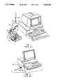
- FIG. 1 of the drawingsA modem 10 is shown near a telephone base 12 which cradles a telephone receiver 14. Modem 10 is electrically connected to the telephone with a telephone extension line 20 utilizing physical/electrical media connectors at each end. Signals transmitted by a modem at a remote location are received over a telephone line 16. An RJ-11 physical/electrical media connector 18 is used to physically and electrically connect a local telephone extension line 20 to telephone line 16. Another RJ-11 connector is used to connect extension line 20 to modem 10.
- Modem 10converts the modem frequency signal back to binary digital data characters. The digital characters are then transmitted through a multiplexed cable 22 to an input port of a receiving computer 24.
- a DAA circuitis located within modem 10 at the point where the modem interfaces with telephone extension line 20. At this location, the DAA circuit isolates the modem and the computer from disturbances coming in or going out over the phone line.
- External modems like modem 10are often employed by users of personal computers. External modems have been popular because they can easily contain a substantial amount of electronic circuitry or hardware, as well as executable programs or software.
- FIG. 2An integral internal modem 30 is located within the housing of a portable computer 32 at a position giving access to local telephone extension line 20.
- the interface between telephone line 20 and modem 30is achieved through the use of an RJ-11 physical/electrical media connector and an internal DAA 34.
- the RJ-11 physical/electrical media connectorhas two components: an RJ-11 socket 36 and an RJ-11 plug 38.
- RJ-11 socket 36is formed in the housing of computer 32. This socket is capable of receiving an RJ-11 plug 38 from any of the many telephone lines utilizing an RJ-11 physical/electrical media connector system.
- the ubiquity of the RJ-11 systemprovides users of portable computers with internal modems a uniform standard interface for media access devices such as modems.
- Modem manufacturerscan build products capable of accepting the RJ-11 media connector with confidence that their product can be used in a wide geographical area. Because modems can be built to the RJ-11 uniform standard, consumers benefit from the ability to interchange and interconnect media access devices without the need for adapters for products made by different manufacturers.
- PCMCIAPersonal Computer Memory Card International Association
- communications card illustratedserves the functions of a modem, a similar card has been contemplated for use in LANs.
- FIG. 4illustrates a 68 pin socket 42 which is pressed over a corresponding plug affixed to the circuit board of the computer.
- This plug and socket arrangementprovides versatility in the selection of cards that a user may select for use with the computer. For example, extra memory cards also utilize the same PCMCIA architecture standards and may therefore be inserted over the same plug as is used with communications card 40.
- FIG. 5illustrates a peripheral socket 44 in PCMCIA communications card 40.
- socket 44is built into communications card 40 to correspond to the variety of plugs employed by different manufacturers.
- socket 44is used to interface with external media access units that contain elements of integrated modems that have not been included within PCMCIA communications card 40.
- Elements not included within the communications card illustrated in FIG. 5include the RJ-type connector interface and the DAA.
- the DAA and the connector interface used in the system illustrated in FIG. 5are housed in an external unit (often referred to as an "intermediate physical/electrical connector” or “podule”).
- an external unitoften referred to as an "intermediate physical/electrical connector” or “podule”
- 68 pin socket 42is standardized as part of the PCMCIA architecture, the shape and configuration of peripheral socket 44 varies with the needs of the manufacturers of the external intermediate physical/electrical connectors.
- FIG. 6illustrates another form of a peripheral socket like peripheral socket 44 illustrated in FIG. 5.
- External intermediate physical/electrical connector socket 46has a shape capable of receiving a corresponding plug for use with the DAA and RJ-11 interface housed in a podule for modem transmissions or an 8 pin modular plug interface for use with LANs.
- Socket 46is manufactured into communications card 40 for use with a specific external DAA and RJ-11 interface podule.
- the RJ-11 media connectoris available at most locations providing telephone service, a user will still be unable to utilize an integral modem if a compatible external DAA and RJ-11 interface podule corresponding to socket 46 is not available.
- FIG. 7depicts communications card 40 inside of a down-sized or laptop computer.
- External intermediate physical/electrical connector socket 46is shown incorporated into communications card 40 and extending to an exposed position so that connection can be made therewith.
- An intermediate physical/electrical connector podule 48houses an external DAA 50 and RJ-11 enclosed socket 36. Podule 48 may be placed in electrical communication with communications card 40 through an external physical/electrical connector plug 52 and a connector cord 54.
- a telephone lineis physically and electrically connected to RJ-11 enclosed socket 36 with an RJ-11 plug to form a communications interface.
- Incoming signalsare then filtered through external DAA 50 and pass through connector cord 54 to external physical/electrical connector plug 52.
- a second communications interfaceis formed between connector plug 52 and connector socket 46.
- the RJ-11 communications interfaceis widely available, while the second communications interface between connector plug 52 and connector socket 46 is manufacturer-specific.
- signalsAfter passing through the second communications interface, signals are translated from analog modem frequency to binary signals compatible with the computer.
- the depth of a PCMCIA standard communications cardis limited to 5 mm.
- the depth of a media connectorsuch as the RJ-type or 8-pin miniature modular plug is approximately 8-12 mm.
- an RJ-11 or other modular connectorexceeds the depth restrictions imposed by the PCMCIA standards for internal computer components.
- Direct internal connection of the physical/electrical media connectorwould necessitate encroaching on a neighboring card space--an approach advocated by some manufacturers, but requiring the sacrifice of space that could be used to provide additional memory capacity.
- a second problem encountered by users of external DAA'sis that there is no standardization among the various manufacturers of external DAA's.
- intermediate physical/electrical connector podule 48may take several forms, no one form allowing use of an external DAA made by a different manufacturer.
- FIG. 8Another solution advocated by some manufacturers to the incompatibility of the RJ-11 connector with the PCMCIA memory card size constraints is illustrated in FIG. 8.
- PCMCIA communications card 40is shown with an integrated physical/electrical connector 56 attached at the location where enclosed socket 44 is usually located. A small DAA is located within integrated connector 56 to filter signals passing therethrough.
- RJ-11 connector socket 36is formed in a free end 57 of connector 56. The height of connector 56 is approximately 10 mm, thereby allowing RJ-11 socket 36 to be contained therein. Incorporation of integrated connector 56 allows an 8 mm RJ-11 plug to interface with the 5 mm communications card 40.
- FIG. 9illustrates the communications card and connector of FIG. 8 installed in a laptop computer.
- 68 pin socket 42is installed over a corresponding plug in electrical communication with the circuit board of the computer.
- communications card 40complies with the 5 mm PCMCIA size restrictions, the 10 mm integrated connector 56 does not. As a result, integrated connector 56 must either be placed outside of the computer housing or must displace memory cards in adjoining slots.
- Operation of the communications cardrequires only the connection of an RJ-11 plug into RJ-11 enclosed socket 36 or an RJ-45 or 8 pin modular plug for use in LANs.
- Signals received from remote modemsare filtered by the internal DAA and converted by communications card 40.
- the extension of integral connector 56 beyond the housing of the computerexposes the connector to the possibility of breakage even when the connector is not in use.
- the protrusion beyond the normal dimensions of the computeralso interferes with the fit of computer portfolios used in transporting many laptop computers.
- Yet another advancement in the artwould be to provide a direct media connector interface for use in laptop and notebook computers that does not displace contiguous memory cards.
- a further advancement in the artwould be to provide a communications card that complies with the 5 mm PCMCIA memory card space configuration limitations while also providing direct connection with a miniature modular plug physical/electrical media connector.
- a still further advancement in the artwould be to provide a communications card that allows the computer housing to retain its designed shape free from any added protrusions or added external equipment.
- Another advancement in the artwould be to provide a 5 mm PCMCIA-architecture communications card/media connector interface that is capable of being carried internally when not in use.
- Still another advancement in the artwould be to provide a communications card/media connector interface that is free from reliance on an enclosed physical/electrical media connector socket.
- a further advancement in the artwould be to provide a communications card connecting system that is free from reliance upon an external Data Access Arrangement circuit.
- a still further advancement in the artwould be to provide a communications card connecting system that is free from reliance on any components which must be carried externally in addition to the computer.
- Another advancement in the artwould be to provide a LAN adaptor card capable of direct connection with a miniature modular plug physical/electrical media connector.
- Still another advancement in the artwould be to provide a LAN adaptor card that is capable of being carried internally in the computer when not in use.
- Yet another advancement in the artwould be to provide a LAN adaptor card connecting system that is free from reliance on any components which must be carried externally in addition to a portable computer.
- Another object of the present inventionis to provide a direct media connector interface for use in laptop or notebook computers that does not displace contiguous memory cards.
- Yet another object of the present inventionis to provide a communications card that complies with the 5 mm PCMCIA memory card space configuration limitations while also providing direct connection with a miniature modular plug physical/electrical media connector.
- Still another object of the present inventionis to provide a communications card that allows the computer housing to retain its designed shape free from any added protrusions or added external equipment.
- Yet another object of the present inventionis to provide a 5 mm PCMCIA-architecture communications card/media connector interface that is capable of being carried internally when not in use.
- Still another object of the present inventionis to provide a communications card/media connector interface that is free from reliance on an enclosed physical/electrical media connector socket.
- Yet another object of the present inventionis to provide a communications card connecting system that is free from reliance upon an external Data Access Arrangement circuit.
- a further object of the present inventionis to provide a communications card connecting system that is free from reliance on any components which must be carried externally in addition to the computer.
- a still further object of the present inventionis to provide a LAN adaptor card capable of direct connection with a miniature modular plug physical/electrical media connector.
- a further object of the present inventionis to provide a LAN adaptor card that is capable of being carried internally in the computer when not in use.
- Yet another object of the present inventionis to provide a LAN adaptor card connecting system that is free from reliance on any components which must be carried externally in addition to the portable computer.
- an interface for use between a miniature modular plug physical/electrical media connector and a PCMCIA-architecture communications card such as used in laptop and notebook computersis provided.
- the media connector capable of being used with the present inventionhas a biased retention clip, a contact pin block, and contact pins.
- the retention cliphas several standardized characteristics, including a broad fixed end protruding from an outer surface of the contact pin block.
- the broad fixed endtapers abruptly at a transition notch to a narrow free end. A user manipulates the narrow free end to disengage the media connector from the communications card.
- a media connectorsuch as an RJ-type, 6 or 8-pin miniature modular plug
- a media connectoris inserted directly into an aperture in a communications card having a plurality of contact wires in electrical connection with both the computer and the aperture. This direct connection obviates the need for any adapters to facilitate connection of the media connector to the communications card.
- the apertureis sized and configured so as to be capable of receiving the media connector.
- the orientation of the aperture to the communications cardis important as the contact wires must be in electrical contact with the contact pins in the media connector to properly communicate electrical signals therethrough.
- One embodiment of the present inventionutilizes means for biasing a wall of the aperture against the media connector inserted therein to retain the media connector within the aperture.
- the apertureis sized slightly smaller than the media connector and accesses made thereto by compressing the compression arms so as to expand the size of the aperture so that the media connector may be placed therein. After releasing the compression arms the size of the aperture serves to maintain the media connector within the aperture.
- FIG. 1For example, one embodiment utilizes a base and support wall which are capable of being retracted within the housing of the computer.
- Embodiments of the inventionincorporate stirrups of a variety of shapes capable of engaging either the transition notch of the retention clip to retain the physical/electrical media connector against the communications card or the bottom of the contact pin block.
- One embodimentutilizes an open retention channel to provide lateral support to a media connector that is inserted parallel to the face of the communications card.
- a stirrupcaptures the media connector and maintains the media connector in electrical contact with exposed contact wires fixed in the retention channel.
- Another embodiment of the present inventionutilizes an aperture formed perpendicular to the surface of the communications card. Complete passage through the aperture is prevented by a depending stirrup blocking the travel of the contact pin block completely through the aperture.
- This presently preferred embodimentutilizes an angled aperture at an angle of 90° when measured from the plane of the face of the communications card.
- This embodimentovercomes the depth restrictions of the PCMCIA communications architecture by allowing the contact pin block to protrude below the plane of the lower surface of the communications card to a point where it is captured by the depending stirrup and prevented from further travel. Structures formed in the aperture such as a retention ridge capture the biased retention clip and hold the physical/electrical media connector in electrical communication with the retractable access portion of the communications card.
- embodiments of the claimed inventionprovide a retractable access portion of the communications card which can be directly accessed by manipulating an actuating mechanism which releases means for retaining a portion of a communications card within a computer housing thereby allowing means for biasing to push the retractable access portion of the card external to the computer housing.
- the travel of the retractable access portionis limited so that the retractable access portion of the communications card will remain in electrical contact with the remainder of the communications card.
- the media connectorAfter exposure of the retractable access portion of the communications card, the media connector is inserted directly into the aperture to facilitate electrical connection between the telephone line and the computer.
- the retractable access portion of the communications cardis reinserted back into the computer housing to be carried internally when not in use.
- the media connector plugis inserted directly into the aperture in the communications card without any intermediate adaptor, no enclosed RJ-11 or RJ-45 connector socket is needed.
- the elimination of the enclosed RJ-11 or RJ-45 connector socketreduces the overall height required for the media connector interface.
- Additional height reductionis accomplished in some embodiments by angling the aperture relative to the upper face of the communications card. This angular orientation allows the aperture in the communications card to present a longer realized aspect relative to the media connector to allow capture of the transition notch therein.
- the angular orientation of the apertureallows for direct connection of a conventional RJ-11 media connector with the PCMCIA standard communications card.
- the PCMCIA communications card utilized in the present inventionhas an integral DAA. As a result, no extra components need be carried along with the computer to facilitate data transfer over telephone lines. Any readily available RJ-11 media connector may be directly inserted into the aperture in the communications card.
- the present inventionalso contemplates a LAN adaptor connection system utilizing a PCMCIA communications card configured for use with a local area network.
- a physical/electrical media connectoris inserted directly into the aperture in the PCMCIA-architecture LAN adaptor card. This direct connection obviates the need for any external adapters to facilitate connection of the RJ-type media connector to the LAN adaptor card.
- FIG. 1is a perspective view of a prior art external modem
- FIG. 2is a perspective view of a prior art integral modem installed in a portable computer
- FIG. 3is a partially cut away perspective view of a PCMCIA-architecture communications card
- FIG. 4is a perspective view of a 68 pin connector end of a communications card like the PCMCIA communications card illustrated in FIG. 3;
- FIG. 5is an enlarged perspective view of the other end of the PCMCIA-architecture communications card illustrated in FIG. 3 having formed therein a manufacture-specific peripheral socket;
- FIG. 6is an enlarged perspective view of a manufacturer-specific peripheral socket like that illustrated in FIG. 5 utilizing a different podule plug;
- FIG. 7is a partially cut away perspective view of a portable computer having installed therein an PCMCIA-architecture communications card capable of attachment to an intermediate physical/electrical connector;
- FIG. 8is a perspective view of an PCMCIA-architecture communications card utilizing an integral DAA and physical/electrical media connector socket;
- FIG. 9is partially cut away perspective view of an installation of the communications card illustrated in FIG. 8 into a portable computer;
- FIG. 10is a plan view of a first embodiment of an PCMCIA communications card within the scope of the present invention wherein the card is extended ready for insertion by a connector;
- FIG. 11ais a cross-sectional view of a retractable access portion of a communications card of the present invention and mounted in a remainder of the communications card;
- FIG. 11bis a second embodiment of a retractable access portion such as that illustrated in FIG. 11a also mounted in a PCMCIA communications card;
- FIG. 11ca cross-section of the communications card taken along lines 11c-11c in FIG. 10;
- FIG. 12is a partially cut away perspective view of a retractable access portion of a communications card shown mounted within a remaining portion of a communications card;
- FIG. 13is a plan of an PCMCIA-architecture communications card capable of being retracted wholly within the housing of the computer;
- FIG. 14is a perspective view of a computer housing formed so as to reveal the communications card installed therein;
- FIG. 15is a partially broken-away cross-sectional view of a retractable access portion of an PCMCIA communications card having a physical/electrical media connector inserted therein;
- FIG. 16is a partially broken away perspective view of a retractable access portion of an PCMCIA-architecture communications card having a physical/electrical media connector disconnected therefrom;
- FIG. 17is a partially broken away perspective view of one embodiment of an interface between a physical/electrical media connector and a 5 mm PCMCIA communications card incorporating the teachings of the present invention
- FIG. 18is a perspective view of the interconnection of the physical/electrical media connector with the communications card
- FIG. 19is a cross-sectional view taken along lines 19--19 in FIG. 18 further illustrating the inventive interface
- FIG. 20is a cross-sectional view of an embodiment of an interface incorporating the teachings of the present invention.
- FIG. 21is a cross-sectional view of an embodiment of an interface incorporating the teachings of the present invention.
- FIG. 22is a partially broken away perspective view of an embodiment of an interface between a physical/electrical media connector and a 5 mm PCMCIA communications card incorporating the teachings present invention
- FIG. 23is a perspective view of an embodiment of the present invention utilizing a combination of a channel formed in the retractable access portion and a stirrup to retain the physical/electrical media connector therein;
- FIG. 24is a perspective view of the embodiment of the present invention illustrated in FIG. 23 having a physical/electrical media connector retained therein;
- FIG. 25ais a plan view of an embodiment of the present invention utilizing an aperture and compression arms to retain the media connector;
- FIG. 25bis a perspective view of an embodiment of the present invention utilizing a vertical aperture having springs recessed in the sides thereof capable of retaining the physical/electrical media connector therein;
- FIG. 26is a perspective view of an embodiment of the present invention utilizing a vertical aperture and having a retention arm capable of pivoting within the retractable access portion of the card to assist in retaining the physical/electrical media connector in the aperture;
- FIG. 27is a perspective view depicting an embodiment of the present invention utilizing a retention arm like that shown in FIG. 26 to assist in retaining a physical/electrical media connector within a channel formed in the bottom of the retractable access portion;
- FIG. 28is a perspective view of an embodiment of the present invention in a folded position
- FIG. 29illustrates an embodiment of the present invention like that illustrated in FIG. 28 in an open position
- FIG. 30is a perspective view of an embodiment of the present invention using a foldable tongue and angled retention bars to form portions of an aperture within which the physical/electrical media connector may be inserted;
- FIG. 31depicts an embodiment like that illustrated in FIG. 30 having a physical/electrical media connector inserted therein;
- FIG. 32is a perspective view taken from the rear of the embodiment illustrated in FIG. 30 and 31;
- FIG. 33is a cross-sectional view taken along lines 33--33 in FIG. 32;
- FIG. 34is a perspective view of the embodiments illustrated in FIGS. 31 through 33 shown retracted into the housing of the computer;
- FIG. 35is a perspective view of an embodiment of the present invention having a hinged support wall and access wall which function to the physical/electrical media connector;
- FIG. 36is a perspective view of the embodiment illustrated in 35 showing the access wall and support wall in an unfolded position;
- FIG. 37is a perspective view of the present invention using a depending stirrup to prevent passage of the physical/electrical media connector completely through the aperture;
- FIG. 38is a partially broken away elevational view of the embodiment illustrated in FIG. 37 depicting the interaction of the stirrup with the physical/electrical media connector.
- PCMCIA communications cardrefers to a communications card falling within the Personal Computer Memory Card International Association memory card parameters for communications cards having a thickness less than the thickness of a miniature modular jack physical/electrical media connector.
- miniature modular jack physical/electrical media connectorconnotes a media connector such as those connectors having physical attributes described in F.C.C. Part 68, subpart F.
- Specific termssuch as RJ-type, RJ-11, RJ-45, 6-pin miniature modular plug, 8-pin miniature modular plug, etc. are all references to specific exemplary physical/electrical media connectors falling within the broader parameters of the term physical/electrical media connectors and should not be used to limit the scope of the invention to specific connectors.
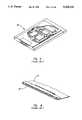
- FIG. 10illustrates a PCMCIA communications card 70 having a retractable access portion 72 and a fixed portion 74.
- Fixed portion 74is in electrical communication with a computer (not shown).
- Retractable access portion 72is in electrical communication with fixed portion 74 through a flexible wire ribbon 75.
- Retractable access portion 72slides in and out of a slot 76 formed within communications card 70.
- Retractable portion 72is urged out of slot 76 by a spring 78.
- the communications cardsuch as illustrated in FIG. 10 is provided with means for biasing the retractable access portion of the communications card in a direction external to the computer housing.
- the biasing means of the embodiment illustrated in FIG. 10comprise spring 78 and at least one spring ramp 79.
- a retention notch 80 in combination with a biased lever 82retains retractable access portion 72 within the housing of the computer.
- the communications cardsuch as is illustrated in FIG. 10 is provided with means for selectively retaining the retractable access portion of the communications card within the computer housing.
- the selective retention means of the embodiment illustrated in FIG. 10comprise retention notch 80 and biased lever 82.
- a limiting notch 84is engaged by biased lever 82 when the communications card is extended from the computer housing.
- a communications cardsuch as the communications card illustrated in FIG. 10 is provided with means for restricting the travel of the retractable access portion of the communications card to a predetermined distance.
- the travel restricting means of the embodiment illustrated in FIG. 10comprise biased lever 82 and limiting notch 84.
- Biased lever 82serves as an actuating mechanism to initiate exposure or retraction of the retractable access portion of the communications card.
- an aperture 86 having a plurality of walls 88is formed within retractable access portion 72.
- Aperture 86is so sized and shaped as to be capable of receiving a physical/electrical media connector.
- Within aperture 86is formed a broad retention clip groove 90, a narrow retention clip groove 92, and a retention ridge 94.
- the structures within aperture 86provide for the retention of a connector pin block of a physical/electrical media connector.
- a guide track 96is formed within communications card 70 protruding upwardly from the bottom of communications card 70. Guide track 96 is interengaged with a corresponding guide groove formed in the bottom of retractable access portion 72.
- biased lever 82When a user wishes to connect a telephone line to the communications card, biased lever 82 is manipulated out of retention notch 80. As retractable access portion 72 is released from the grip of biased lever 82, tension applied by spring 78 urges retractable access portion 72 out of slot 76. The progress of retractable access portion 72 is guided by guide track 96 and is halted when biased lever 82 engages limiting notch 84. A user then inserts a physical/electrical media connector into aperture 86 to provide an electrical connection between communications card 70 and the telephone line.
- a communications cardsuch as communications card 70 provides means for biasing the retractable access portion of the communications card in a direction away from the computer housing.
- the biasing means employed in the embodiment illustrated in FIG. 10comprise sprung wire 78.
- the userWhen a user no longer wishes access to retractable access portion 72, the user merely presses retractable access portion 72 back within the confines of the computer housing such that retention notch 80 will be engaged by biased lever 82 to prevent inadvertent exposure of retractable access portion 72 outside of the computer housing.
- a communications cardsuch as communications card 70 is provided with means for selectively retaining the retractable access portion of the communications card within a computer housing.
- the selective retention means at the embodiment illustrated in FIG. 10comprise retention notch 80 and biased lever 82.
- the physical/electrical media connectoris removed from aperture 86, and biased lever 82 is removed from limiting notch 84. Pressure opposing spring 78 is then applied until biased lever 82 engages retention notch 80. Engagement of biased lever 82 into retention notch 80 secures the communications card within the housing of the computer, thereby protecting the communications card from breakage during transport of the computer.
- Direct connection of a physical/electrical media connector to the communications cardeliminates the need for an external DAA and also eliminates the need for an enclosed physical/electrical media connector socket.
- a communications cardsuch as the communications card illustrated in FIG. 10 is provided with means for maintaining electrical communication between the retractable access portion of the communications card and the fixed remainder of the communications card as the retractable access portion of the communications card travels in and out of the computer housing.
- the electrical communication maintenance means of the embodiment illustrated in FIG. 10comprise flexible wire ribbon 75.
- Flexible wire ribbon 75is connected at one end both physically and electrically to communications card 70.
- the other end of flexible wire ribbon 75is connected both physically and electrically to retractable access portion 72.
- FIG. 11aillustrates retractable access portion 72 of PCMCIA communications card 70 interengaged with fixed portion 74 through the interaction of guide track 96 with guide channel 100.
- a communications cardsuch as communications card 70 illustrated in FIGS. 11a-c provides means for guiding the travel of the retractable access portion of the communications card as the retractable access portion of the communications card travels in and out of the computer housing.
- the guiding means of the embodiment illustrated in FIGS. 11a-ccomprise guide channel 100 and guide track 96.
- the usermanipulates retractable access portion 72 through a slot in the housing in the computer guided by guide track 96 and guide channel 100.
- FIG. 11billustrates an alternate embodiment of the guiding means illustrated in 11a, wherein the guide track 96 and guide channel 100 are reversed such that guide track 96 is formed in fixed portion 74 and guide channel 100 is formed in retractable access portion 72.
- FIG. 11cis a cross-sectional view taken along lines 11c--11c of FIG. 10 illustrating the interaction of retractable access portion 72 with communications card 70.
- Retractable access portion 72is shown having guide channel 100 through which guide track 96 slides when retractable access portion 72 is urged out of slot 76 by spring 78.
- Guide track 96is formed on the bottom of PCMCIA communications card 70 protruding upward whereas guide channel 100 is formed in the bottom of retractable access portion 72.
- FIG. 12illustrates an alternate embodiment of the present invention incorporating a ratcheted groove 102 through which an actuating shaft 104 travels during exposure and retraction of retractable access portion 72.
- retractable access portion 72As retractable access portion 72 is exposed outside of the computer housing, actuating shaft 104 is forced along a linear extended pathway 108 until reaching the end thereof. Further travel of retractable access portion 72 is halted by contact between actuating shaft 104 and the end of linear extended pathway 108. When a user no longer requires exposure of retractable access portion 72, retractable access portion 72 may be manually reinserted through slot 76 until actuating shaft 104 leaves linear extended pathway 108 and continues in a clockwise motion through the chevron-shaped ratcheted groove 102.
- a communications cardsuch as communications card 70 illustrated in FIG. 12 provides means for selectively retaining the retractable access portion of the communications card within the computer housing.
- the selective retention means of the embodiment illustrated in FIG. 12comprise ratcheted groove 102, actuating shaft 104, and linear extended pathway 108.
- FIG. 13illustrates an alternate embodiment of the communications card employing the teachings of the present invention.
- Retractable access portion 72is exposed from the computer housing through the use of a sprung wire 110.
- a communications cardsuch as communications card 70 provides means for biasing the retractable access portion of the communications card in a direction out of the computer housing.
- the biasing means employed in the embodiment illustrated in FIG. 13comprise sprung wire 110.
- a communications cardsuch as communications card 70 is provided with means for selectively retaining the retractable access portion of the communications card within a computer housing.
- the selective retention means of the embodiment illustrated in FIG. 13comprise retention notch 80 and biased lever 82.
- FIG. 14depicts the computer housing having formed therein an access tunnel 123.
- Access tunnel 123allows direct access to communications card 70 from outside of the computer without the need to move communications card 70.
- Media connector 18is inserted through access tunnel 123 directly into communications card 70 to provide a physical and electrical connection between the computer and telephone line 16.
- FIG. 15depicts an inventive interface between a physical/electrical media connector 38 and retractable access portion 72.
- Physical/electrical media connector 38comprises a contact pin block 112, a plurality of contact pins 114, and a biased retention clip 116.
- the biased retention clipcomprises a broad fixed end 118, a narrow free end 120, and a transition notch 122.
- the communications card in FIG. 15may also be provided with means for preventing passage of the contact pin block completely through the aperture in the communications card.
- the passage prevention means of the embodiment illustrated in FIG. 15comprise a ledge 126.
- FIG. 16illustrates a conventional J-11 plug 38 located near retractable access portion 72 of communications card 70.
- RJ-11 plug 38initiates electrical connection between contact wires 124 and contact pine 114 to allow the transfer of data from telephone line 16 to the computer.
- Ledge 126prevents passage of RJ-11 plug 38 entirely through retractable access portion 72 of communications card 70.
- RJ-11 plug 38The physical connection of RJ-11 plug 38 into angled aperture 86 is guided by the insertion of broad fixed end 118 into broad retention clip groove 90 of angled aperture 86. Progress of broad fixed end 118 through broad retention clip groove 90 are not impeded. However, once narrow free end 120 of biased retention clip 116 is pressed beyond retention ridge 94, RJ-11 plug 38 is locked within angled aperture 86. To release RJ-11 plug 38 from angled aperture 86, a user merely presses biased retention clip 116 at narrow free end 120 toward contact pin block 112 and withdraws J-11 plug 38 from angled aperture 86. Transition notch 122 interacts with retention ridge 94 to lock RJ-11 plug 38 into angled aperture 86 when engaged.
- angled aperture 86mirrors closely the function of an enclosed J-11 socket without violating the constraints of the PCMCIA communications card architecture.
- the angle at which angled aperture 86 is formed within this embodiment in retractable access portion 72is thus limited by the restrictions imposed by the PCMCIA architecture.
- Apertures utilizing the teachings of the present invention exhibited in this embodimentare formed within the PCMCIA communications card with angles relative to the surface thereof falling within the range of about 15 degrees to about 60 degrees.
- the preferred angle for the aperture utilized in the embodiment illustrated in FIGS. 10 and 12-16is 20 degrees measured from a line perpendicular to the faces of the communications card.
- FIG. 17illustrates yet another embodiment of the present invention.
- the embodiment illustrated in FIG. 17does not employ an angled aperture, but instead utilizes a perpendicular aperture 130 formed within retractable access portion 72 of communications card 40.
- Such an arrangementrequires that additional structures be incorporated into the communications card to either capture retention clip 116 as the clip protrudes above the communications card or to support the lower end of pin block 112 if it protrudes below the communications card.
- the 8-15 mm connectormust protrude from at least one face of the communications card when inserted in a perpendicular orientation relative to the face of that card.
- an aperturesuch as the aperture illustrated in FIG. 17 is provided with means for securing the physical/electrical connector within the aperture in the communications card.
- the securing means of the embodiment illustrated in FIG. 17comprise biased retention stirrup 132.
- Stirrup 132is pivotally biased by a stirrup spring 134 about the longitudinal axis of a pivot pin 136.
- Stirrup spring 134biases stirrup 132 by way of example in a clockwise direction in the embodiment illustrated in FIG. 17.
- the natural state of repose for stirrup 132is shown in phantom lines.
- stirrup 132When use of perpendicular aperture 130 is desired, stirrup 132 is pivoted out of aperture 130 into a recess 138 thereby removing any obstruction to plug 38 as plug 38 is inserted into aperture 130. In the embodiment illustrated in FIG. 17, travel of plug 38 through aperture 130 is limited by a stop 140 which protrudes into aperture 130. Upon abutment of plug 38 with stop 140, stirrup 132 may be released to pivot under urging from spring 134 into contact with the portion of plug 38 protruding from the upper face of retractable access portion 72.
- Stirrup 132is configured so as to have a retention tab 142 projecting from stirrup 132 so as to be capable of engaging transition notch 122 when plug 38 is abutting stop 140 in aperture 130.
- Spring 134maintains engagement of retention tabs 142 with transition notch 122 when connection is made between plug 38 and aperture 130.
- a retractable access portion of a communications cardsuch as retractable access portion 72 illustrated in FIG. 18 is provided with means for securing the physical/electrical connector within the aperture in the communications card.
- the securing means of the embodiment illustrated in FIG. 18comprise a biased biarcuate stirrup 144.
- Biarcuate stirrup 144is pivotally biased against plug 38. Retention of plug 38 with aperture 130 is accomplished through the biarcuate shape of biarcuate stirrup 144.
- biarcuatedescribes any stirrup having a depending attachment leg 146 and a retention leg 148, two attachment legs being positioned apart a distance at least as wide as broad fixed end 18, and the retention legs being capable of engaging transition notch 122.
- biarcuate stirrup 144when biarcuate stirrup 144 is pressed into recess 138, tension produced by stirrup spring 134 urges biarcuate stirrup 144 into aperture 130. While biarcuate stirrup 144 may be manipulated out of aperture 130 prior to use, it is preferable to have biarcuate stirrup housed so as not to block entry of plug 38 into aperture 130.
- a stirrupsuch as the stirrup illustrated in FIG. 18 is provided with means for selectively restraining a stirrup from obstructing the aperture.
- the restraining means illustrated in FIG. 18comprise a locking disk 150.
- Locking disk 150selectively engages a stirrup such as biarcuate stirrup 144 to prevent pivoting of biarcuate stirrup 144 into an aperture such as aperture 130.
- FIG. 19is a cross-sectional view taken along lines 19--19 in FIG. 18 illustrating more specifically the interaction between aperture 130 and plug 38.
- Biarcuate stirrup 144is shown engaged with transition notch 122 of biased retention clip 116. Tension produced between biased retention clip 116 and stirrup spring 134 via biarcuate stirrup 144 maintains the engagement of biarcuate stirrup 144 with transition notch 122.
- a userdisengages biarcuate stirrup 144 from transition notch 122 by pressing biarcuate stirrup 144 into recess 138 while withdrawing plug 38 from abutment with stop 140 in aperture 130.
- biarcuate stirrup 144will be biased by stirrup spring 134 into aperture 130.
- Aperture 130is positioned within retractable access portion 72 to allow electrical contact between contact wires 124 and the plurality of electrical contact pins 114 located in contact pin block 112.
- Locking disk 150selectively engages biarcuate stirrup 144 to prevent pivoting of biarcuate stirrup 144 into aperture 130.
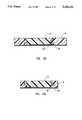
- FIG. 20illustrates a retractable access portion 72 of a communications card having formed therein perpendicular aperture 130 as illustrated in FIG. 19.
- the embodiment of the present invention illustrated in FIG. 20differs from that in FIG. 19 in that plug 38 is not stopped by a protrusion from the wall of aperture 130, but is instead allowed to pass partially through retractable access portion 72. Partial passage of plug 38 through retractable access portion 72 allows transition notch 122 of biased retention clip 116 to be engaged by a perpendicular retention ridge 152 formed within aperture 130.
- a retractable access portion of a communications card like that illustrated in FIG. 20is provided with means for preventing passage of the plug completely through the aperture.
- the passage prevention means of the embodiment illustrated in FIG. 20comprise a pivot arm 154. Pivot arm 154 is biased into aperture 130 by a pivot arm spring 156.
- plug 38forces pivot arm 154 out of aperture 130 into a position below and perpendicular to a lower face 158 of retractable access portion 72.
- a depending arm 160 of pivot arm 154is perpendicular to face 158.
- An abutment arm 162protrudes perpendicular to depending arm 160.
- FIG. 21illustrates the presently preferred embodiment of the present invention.
- stirrup 174Upon introduction of plug 38 into aperture 130, stirrup 174 is pivoted out of an orientation parallel with lower surface 158 into a perpendicular orientation therewith. Upon reaching a depending condition, stirrup 174 prevents further passage of plug 38 through aperture 130. At this point a sufficient portion of plug 38 is extending below surface 158 to allow capture of the transition notch of the bias retention clip by the retention ridge formed in the wall of aperture 130. The sufficient portion of the electrical contacts within plug 38 remain in the aperture 130 to afford electrical communication with the contact wires formed within the retractable access portion of the communications card.
- a retractable access portion of a communications card like that illustrated in FIG. 21is provided with means for preventing passage of the plug completely through the aperture.
- the passage prevention means of the embodiment illustrated in FIG. 21comprise a pivoting dependant stirrup 174. Although retraction of the retractable access portion will pivot the stirrup into aperture 130 without the need for a spring, stirrup 174 may be biased into the aperture 130 by a spring 176.
- FIG. 22illustrates an embodiment of the present invention utilizing a retention channel with a longitudinal axis parallel with and formed in lower face 158.
- Retention channel 170serves to resist lateral movement of plug 38.
- Channel 170terminates in an end wall 172 against which plug 38 abuts when fully inserted into channel 170.
- Plug 38is held in channel 170 by a support stirrup 174 pivotally attached to retractable access portion 72.
- a spring 176biases support stirrup 174 into channel 170.
- support stirrup 174will be pivoted out of channel 170 and plug 38 will be inserted into support stirrup 174.
- Plug 38is inserted into channel 170 until contact pin block 112 abuts end wall 172 whereupon support stirrup 174 engages transition notch 122 of biased retention clip 116.
- a userpresses biased retention clip 116 toward contact pin block 112 thereby disengaging support stirrup 174 from transition notch 122.
- FIG. 23illustrates an embodiment of the present invention wherein retractable access portion 72 has formed therein a channel 202 which supports contact pin block 112.
- Channel 202is shaped so as to conform to contact pin block 112.
- a stirrup 204is positioned within retractable access portion 72 so as to pivot in a 90 degree arch from a position substantially parallel with retractable access portion 72 to a position substantially perpendicular thereto.
- Stirrup 204is biased by a spring 206 in a direction substantially parallel with retractable access portion 72.
- stirrup 204is pulled into a perpendicular position to retractable access portion 72 and plug 38 is inserted into channel 202 until plug 38 abuts an end wall 208 of channel 202. Stirrup 204 is then released from its perpendicular position and is urged by spring 206 into contact with the top of plug 38.
- stirrup 204When connection of the RJ-11 phone jack is no longer needed, stirrup 204 is lifted back into a perpendicular position and plug 38 can be removed from channel 202. Biasing of spring 206 will then urge stirrup 204 back into channel 202 and retractable access portion 72 can be retracted.
- stirrup 204The configuration of stirrup 204 is best appreciated by reference to FIG. 24 in which stirrup 204 is shown having a bridge 210 and contact points 212. Free ends 214 of stirrup 204 engage apertures (not shown) formed in retractable access portion 72.
- FIG. 25aAnother embodiment of the present invention is illustrated in FIG. 25a wherein plug 38 is shown inserted into an aperture 216. It will be noted that in the embodiment illustrated in FIG. 25a, there is no means for engaging the retaining clip. Instead, the physical/electrical media connector is held in place by friction produced by means for biasing a wall of the aperture against the media connector inserted therein to retain the media connector with the aperture.
- the means for biasing a wall of the aperture utilized in the embodiment illustrated in FIG. 25acomprises compression arms 217.
- compression arms 217By forming aperture 216 slightly smaller than the media connector, friction is created which maintains the media connector within the aperture.
- compression arms 217are biased toward one another by the fingers of the user. This biasing action increases the dimensions of the aperture thereby releasing the media connector allowing the media connector to be removed.
- FIG. 25bAnother embodiment of the present invention utilizing friction to retain the media connector inside the aperture is depicted in FIG. 25b.
- a spring 218is mounted within a wall 220 of aperture 216 opposite biased retention clip 116.
- Aperture 216is formed with a recess 222 which is formed so as to conform to the shape of biased retention clip 116.
- biased retention clip 116reacts by exerting a compressive force against plug 38 from the side of the aperture containing recess 222.
- the combined compressive forces of spring 218 and biased retention clip 116serve to retain plug 38 within aperture 216.
- Contact wires 124also positioned in wall 220 are placed in electrical communication with contact pins 114 in contact pin block 112 when plug 38 is fully inserted within aperture 216.
- spring 218is located opposite biased retention clip 116 in the embodiment illustrated in FIG. 25, it will be appreciated that one or more springs may be located in any or all of the walls 220 surrounding aperture 216 to produce a retentive force.
- aperture 216is so sized and shaped as to be capable of accepting plug 38.
- Aperture 216is formed in retractable access portion 72 and has a recess 223 shaped so as to be capable of accepting biased retention clip 116.
- a retaining arm 224is pivotally attached to retractable access portion 72 and is capable of pivoting from a groove 226 formed in retractable access portion 72 through a 90 degree arc so as to be substantially perpendicular to retractable access portion 72. When not in use, retaining arm 224 is pivoted down into groove 226 so that retractable access portion 72 may be retracted.
- retaining arm 224When plug 38 is inserted into aperture 216, retaining arm 224 may be pivoted out of groove 226 past biased retention clip 116 into the position illustrated in FIG. 26.
- electrical communicationoccurs between contact pins 114 in plug 38 and contact wires fixed in the wall of aperture 216.
- FIG. 27another embodiment of the present invention is illustrated in which a channel 228 is formed in the bottom face of retractable access portion 72.
- Channel 228is so sized and configured as to be capable of receiving a portion of a physical/electrical media connector.
- a pivoting retention clip 230is capable of pivoting from a position substantially parallel to the retractable access portion 72 to a position perpendicular to retractable access portion 72. When plug 38 is inserted into channel 228, pivoting retention clip 230 can be pivoted up out of retractable access portion 72 and over the back of plug 38 to thereby retain plug 38 in channel 228.
- a spring loaded pivot block 232operates within channel 228 to assist in retaining the physical/electrical media connector within channel 228.
- Pivot block 232is capable of being pivoted so that the physical/electrical media connector may be inserted thereby. Thereafter, by elevating the nonpivoting of the block farthest away from plug 38, the block may be forced upward thereby blocking removal of the physical/electrical media connector from channel 228.
- a corner of the pivot block nearest plug 38may then be depressed so that pivot block 232 is once again flush with the bottom of channel 228.
- pivot block 232must be located behind plug 38 a distance so as to allow pivotable movement of pivot block 232 when plug 38 is channel 228.
- retention clip 230is pivoted into a groove (not shown) formed in retractable access portion 72.
- Retractable access portion 72may then be retracted without interference from retention clip 230 or pivot block 232.
- Contact pine 114 in plug 38are placed in electrical communication with contact wires 124 (not shown) when plug 38 is retained in channel 228.
- pivotal member 236 and pivotal member 238have a common pivotal access 240 and are capable of being positioned substantially parallel to retractable access portion 72 when retractable access portion 72 is retracted, and are also capable of being pivoted to a position perpendicular to retractable access portion 72.
- a composite aperture 234is formed within pivotal member 236 and pivotal member 238.
- Aperture 234is so sized and shaped so as to be capable of accepting a physical/electrical media connector therein.
- contact pins 114 in plug 38come into electrical communication with contact wires 124 formed within an inside surface of upper pivotal member 236.
- biased retention clip 116is biased in a direction toward the contact pin block and the physical/electrical media connector may be removed.
- Upper pivotal member 236is wider than lower pivotal member 238 and both pivot at common pivotal access 240.
- a pivot pin 244passes through both pivotal member 236 and pivotal member 238 at axis 240 and is affixed to arms forming retractable access portion 72.
- Upper pivotal member 236provides only the roof of aperture of composite 234 with the remainder of the aperture being provided by lower pivotal member 238.
- lower pivotal member 238is pivoted into a position substantially parallel with the retractable access portion 72 and upper pivotal member 236 is pivoted over lower pivotal member 238 into a position substantially parallel with retractable access portion 72.
- FIG. 30an embodiment of the present invention is illustrated in which three structures cooperate to form portions of a partial aperture 250.
- the three structures which cooperate to form partial aperture 250are tongue 252, and angled retention bars 254 and 256. Angled retention bars 254 and 256 are joined by horizontal guide pins 258.
- Vertical guide bars 260join tongue 252 to angled retention bars 254 and 256.
- a spring 262operates to bias apart angled retention bars 254 and 256.
- Stop 264is positioned so as to limit the travel of angled retention bars 254 and 256 to a point where partial aperture 250 is so sized and shaped so as to be capable of accepting a physical/electrical media connector.
- Contact wires 124are located in tongue 252 and are capable of establishing electrical communication with contact pins in plug 38.
- a retention notch 266is formed within in the angled retention bars 254 and 256 and is capable of engaging structures on the physical/electrical media connector to retain the physical/electrical media connector within partial aperture 250.
- FIG. 31depicts the embodiment illustrated in FIG. 30 where plug 38 is inserted therein.
- Retention ledge 266is shown having retained therein the transition notch 122 of the biased retention clip 116.
- FIG. 32depicts partial aperture 250 when viewed from the rear of the aperture.
- the structures forming partial aperture 250are joined to the stationary portion of the communications card by an anchor 263.
- the bottom of plug 38is supported by tongue 252 and electrical communication occurs at contact wires 124.
- FIG. 33is a cross-section taken along lines 33--33 in FIG. 32 illustrating the pivotal elements of that embodiment.
- Vertical guide bars 260are capable of pivoting upward in a counter-clockwise direction when viewed in FIG. 33, and tongue 252 is capable of being folded into the area between vertical guide bars 260 prior to retraction of the partial aperture into the remainder of the communications card.
- tongue 252 and vertical support bars 260are pivoted up into a position parallel with retractable access portion 72, angled retention bars 254 and 256 are pressed together into a configuration depicted in FIG. 34.
- those structuresmay then be retracted into the remainder of the communications card.
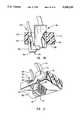
- FIG. 35Another embodiment of the present invention is illustrated in FIG. 35 in which a retractable access portion 72 houses an aperture support structure 268.
- Aperture support structure 268comprises hinge 270 joining a support wall 272 to an access wall 274.
- Formed within access wall 274is an aperture 276 which is so sized and configured so as to be capable of accepting a physical/electrical media connector.
- Support wall 272serves to not only support the top of access wall 274, but also houses contact wires 124 which were placed in electrical communication with contact pins located within the physical/electrical media connector when the media connector is inserted into aperture 276.
- a base 278has formed therein a track 280 which directs guides 282 formed in the lower edge of access wall 274.
- Guides 282are shaped so as to not only slide within tract 280, but also serve to retain the lower edge of access wall 274 against base 278.
- aperture support structure 268When a user wishes to utilize aperture support structure 268, pressure is exerted by the user against the base of access wall 274 causing compression near hinge 270. As illustrated in FIG. 36, this compression results in the elevation of both support wall 272 and access wall 274.
- a stop located within track 280halts the progress of guides 282 and thereby positions access wall 274 in proper alignment with support wall 272 to provide electrical communication between the physical/electrical media connector contact pins and contact wires 124.
- base 278, access wall 274 and support wall 272provide support for and retain the physical/electrical media connector therein.
- base 278serves to support the bottom edge of the physical/electrical media connector while aperture 276 serves to limit the lateral travel of the physical/electrical media connector.
- a notch 284is so sized and configured so as to be capable of engaging the transition notch of the biased retention clip.
- the biased retention clipWhen the user wishes to remove the physical/electrical media connector from the aperture support structure, the biased retention clip is pressed toward the contact pin block and a physical/electrical media connector is removed from aperture 276. Thereafter, pressure is applied in the area of hinge 270 to flatten aperture support structure 268. When flattened, aperture support structure 268 maybe retracted within the communications card.
- retractable access portion 72houses an aperture 286 capable of accepting a physical/electrical media connector.
- Contact wires 124protrude into aperture 286 so as to be capable of making electrical communication with contact pins located within the physical/electrical media connector when the physical/electrical media connector is inserted into aperture 286.
- a stirrup 288limits the progress of the physical/electrical media connector through aperture 286.
- stirrup 288is pivotally engaged in retractable access portion 72 and depends therefrom. As stirrup 288 is positioned so as to pass across a portion of aperture 286, the physical/electrical media connector cannot pass therethrough. The physical/electrical media connector rests on stirrup 288 when the communications card is in use.
- the present inventionobviates the need for any external podule or other device that must be carried externally in addition to the computer. If a portable computer is to be transported, the telephone line and compatible physical/electrical media connector can be easily disconnected and the communications card may then be retracted into the housing of the computer. Retraction of the communications card prevents breakage and allows portfolios designed to carry the computer to function in a normal manner without the impedance of any apparatus protruding from the side of the computer housing.
Landscapes
- Engineering & Computer Science (AREA)
- Theoretical Computer Science (AREA)
- Computer Hardware Design (AREA)
- Physics & Mathematics (AREA)
- General Engineering & Computer Science (AREA)
- Human Computer Interaction (AREA)
- General Physics & Mathematics (AREA)
- Mathematical Physics (AREA)
- Coupling Device And Connection With Printed Circuit (AREA)
- Details Of Connecting Devices For Male And Female Coupling (AREA)
- Telephonic Communication Services (AREA)
Abstract
Description
Claims (24)
Priority Applications (10)
| Application Number | Priority Date | Filing Date | Title |
|---|---|---|---|
| US08/040,656US5338210A (en) | 1992-04-08 | 1993-03-31 | Media connector interface for use with a PCMCIA-architecture communications card |
| JP5149517AJP2810840B2 (en) | 1993-03-31 | 1993-06-21 | Media connector interface for communication card with PCMCIA structure |
| US08/291,277US5547401A (en) | 1992-04-08 | 1994-08-16 | Media connector interface for use with a thin-architecture communications card |
| US08/662,675US5816832A (en) | 1992-04-08 | 1996-06-14 | Media connector interface for use with a PCMCIA-architecture communications card |
| US08/689,715US5727972A (en) | 1992-04-08 | 1996-08-16 | Media connector interface for use with a thin-architecture communications card |
| US08/865,553US6266017B1 (en) | 1992-04-08 | 1997-05-29 | Retractable antenna system |
| US08/991,074US5938480A (en) | 1992-04-08 | 1997-12-16 | Media connector interface for use with electrical apparatus |
| US09/100,524US5975927A (en) | 1992-04-08 | 1998-06-18 | Communications card having rotating communications port |
| US09/183,835US6099329A (en) | 1992-04-08 | 1998-10-30 | Retractable coaxial jack |
| US09/357,017US6561824B1 (en) | 1992-04-08 | 1999-07-19 | Media connector interface for electrical apparatus |
Applications Claiming Priority (3)
| Application Number | Priority Date | Filing Date | Title |
|---|---|---|---|
| US07/866,670US5183404A (en) | 1992-04-08 | 1992-04-08 | Systems for connection of physical/electrical media connectors to computer communications cards |
| US97425392A | 1992-11-10 | 1992-11-10 | |
| US08/040,656US5338210A (en) | 1992-04-08 | 1993-03-31 | Media connector interface for use with a PCMCIA-architecture communications card |
Related Parent Applications (2)
| Application Number | Title | Priority Date | Filing Date |
|---|---|---|---|
| US07/974,252Continuation-In-PartUS5330062A (en) | 1992-04-08 | 1992-11-10 | Light tree display for a horizontal carousel |
| US97425392AContinuation-In-Part | 1992-04-08 | 1992-11-10 |
Related Child Applications (1)
| Application Number | Title | Priority Date | Filing Date |
|---|---|---|---|
| US08/291,277Continuation-In-PartUS5547401A (en) | 1992-04-08 | 1994-08-16 | Media connector interface for use with a thin-architecture communications card |
Publications (1)
| Publication Number | Publication Date |
|---|---|
| US5338210Atrue US5338210A (en) | 1994-08-16 |
Family
ID=25348122
Family Applications (3)
| Application Number | Title | Priority Date | Filing Date |
|---|---|---|---|
| US07/866,670Expired - LifetimeUS5183404A (en) | 1992-04-08 | 1992-04-08 | Systems for connection of physical/electrical media connectors to computer communications cards |
| US08/040,656Expired - LifetimeUS5338210A (en) | 1992-04-08 | 1993-03-31 | Media connector interface for use with a PCMCIA-architecture communications card |
| US08/131,012Expired - LifetimeUS5336099A (en) | 1992-04-08 | 1993-10-01 | Media connector interface for use with a PCMCIA-architecture communications card |
Family Applications Before (1)
| Application Number | Title | Priority Date | Filing Date |
|---|---|---|---|
| US07/866,670Expired - LifetimeUS5183404A (en) | 1992-04-08 | 1992-04-08 | Systems for connection of physical/electrical media connectors to computer communications cards |
Family Applications After (1)
| Application Number | Title | Priority Date | Filing Date |
|---|---|---|---|
| US08/131,012Expired - LifetimeUS5336099A (en) | 1992-04-08 | 1993-10-01 | Media connector interface for use with a PCMCIA-architecture communications card |
Country Status (9)
| Country | Link |
|---|---|
| US (3) | US5183404A (en) |
| JP (1) | JPH07122842B2 (en) |
| AU (1) | AU653672B2 (en) |
| CA (1) | CA2070571C (en) |
| DE (1) | DE4304880C2 (en) |
| FR (1) | FR2689987B1 (en) |
| GB (1) | GB2267999B (en) |
| SE (1) | SE513968C2 (en) |
| SG (4) | SG48337A1 (en) |
Cited By (99)
| Publication number | Priority date | Publication date | Assignee | Title |
|---|---|---|---|---|
| USD357007S (en) | 1993-05-07 | 1995-04-04 | International Business Machines Corp. | Media access module connector for credit card adapters |
| US5411405A (en)* | 1993-11-12 | 1995-05-02 | Angia Communications, Inc. | Miniature electrical communications connectors |
| USD361989S (en) | 1993-05-07 | 1995-09-05 | International Business Machines Corporation | Media access module connector for credit card adapters |
| US5493477A (en)* | 1993-09-10 | 1996-02-20 | Honda Tsushin Kogyo Kabushiki Kaisha | IC card device |
| US5505633A (en)* | 1994-05-13 | 1996-04-09 | Intel Corporation | Integral external connector interface for thin form factor computer cards |
| US5537558A (en)* | 1994-10-05 | 1996-07-16 | Halliburton Company | Apparatus and method for communicating multiple devices through one PCMCIA interface |
| USD371770S (en) | 1995-03-06 | 1996-07-16 | Motorola, Inc. | Wireless modem enclosure |
| US5538442A (en)* | 1993-10-04 | 1996-07-23 | Murata Mfg. Co., Ltd. | Communication card |
| US5547401A (en)* | 1992-04-08 | 1996-08-20 | Megahertz Corporation | Media connector interface for use with a thin-architecture communications card |
| US5549115A (en)* | 1994-09-28 | 1996-08-27 | Heartstream, Inc. | Method and apparatus for gathering event data using a removable data storage medium and clock |
| US5562504A (en)* | 1995-01-04 | 1996-10-08 | Simple Technology Incorporated | Communications card with integral transmission media line adaptor |
| US5575669A (en)* | 1993-12-23 | 1996-11-19 | Lin; Carol S. M. | Ejection mechanism for expansion card |
| GB2300981A (en)* | 1995-05-18 | 1996-11-20 | Nec Corp | Connector for portable information apparatus |
| US5615344A (en)* | 1992-11-12 | 1997-03-25 | New Media Corp. | Apparatus used to interface a peripheral device to a computer employing a reconfigurable interface circuit |
| US5641314A (en)* | 1995-06-30 | 1997-06-24 | The Whitaker Corporation | Memory card receptacle connector and contact terminal |
| US5655143A (en)* | 1994-04-21 | 1997-08-05 | Alpert; Martin A. | PCMICIA card-like device with internal retractable cord mechanism |
| US5660568A (en)* | 1995-01-04 | 1997-08-26 | Simple Technology, Inc. | Communications card with integral transmission media line adaptor |
| US5667395A (en)* | 1994-08-29 | 1997-09-16 | Murata Mfg. Co., Ltd. | Communication card and structure of jack for use in the same |
| US5679013A (en)* | 1994-11-14 | 1997-10-21 | International Business Machines Corporation | Electrical connector and an electronic apparatus using the electrical connector |
| US5692914A (en)* | 1995-01-24 | 1997-12-02 | Mitsubishi Denki Kabushiki Kaisha | PC card including a jack for a connector |
| US5727966A (en)* | 1994-04-21 | 1998-03-17 | Alpert; Martin | Foldable connector assembly for miniature circuit card |
| US5773332A (en)* | 1993-11-12 | 1998-06-30 | Xircom, Inc. | Adaptable communications connectors |
| US5805929A (en)* | 1996-01-29 | 1998-09-08 | International Business Machines Corporation | Multiple independent I/O functions on a PCMCIA card share a single interrupt request signal using an AND gate for triggering a delayed RESET signal |
| US5823796A (en)* | 1996-04-02 | 1998-10-20 | Itt Manufacturing Enterprises, Inc. | Audio/power jack for IC card |
| USD405764S (en) | 1998-04-22 | 1999-02-16 | Simple Technology Inc. | Adaptor for a media line connector |
| US5876218A (en)* | 1997-05-28 | 1999-03-02 | Gateway 2000, Inc. | Piggy back PC card |
| JP2882571B2 (en) | 1994-08-18 | 1999-04-12 | インターナショナル・ビジネス・マシーンズ・コーポレイション | Pull-out jack |
| JP2921407B2 (en) | 1994-08-24 | 1999-07-19 | 株式会社村田製作所 | Communication card |
| JP2920728B2 (en) | 1994-08-29 | 1999-07-19 | 株式会社村田製作所 | Communication card |
| JP2921411B2 (en) | 1994-08-31 | 1999-07-19 | 株式会社村田製作所 | Communication card |
| US5954808A (en)* | 1997-09-17 | 1999-09-21 | Micron Electronics, Inc. | Method for configuring a computer-based system with a configuration card |
| WO1999041805A3 (en)* | 1998-02-17 | 1999-09-30 | Xircom Inc | Compliant communications connectors |
| US5971777A (en)* | 1997-11-21 | 1999-10-26 | 3Com Corporation | Breakaway physical/electrical media jack |
| US5984731A (en)* | 1997-11-17 | 1999-11-16 | Xircom, Inc. | Removable I/O device with integrated receptacles for receiving standard plugs |
| US5991875A (en)* | 1997-09-17 | 1999-11-23 | Micron Electronics, Inc. | System configuration card |
| US6000957A (en)* | 1997-12-29 | 1999-12-14 | Itt Manufacturing Enterprises, Inc. | PC card extendable interface |
| US6005774A (en)* | 1994-12-09 | 1999-12-21 | International Business Machines Corporation | Integrated circuit card |
| US6019630A (en)* | 1994-04-21 | 2000-02-01 | Click Technologies, Inc. | Foldable connector assembly for miniature circuit card |
| US6033240A (en)* | 1998-10-30 | 2000-03-07 | 3Com Corporation | Retractable media jack operable with two discrete media connectors |
| US6041257A (en)* | 1994-09-28 | 2000-03-21 | Heartstream | Method of using a measuring instrument and data gathering system |
| US6045393A (en)* | 1994-04-21 | 2000-04-04 | Click Technologies, Inc. | Foldable connector assembly for miniature circuit card |
| US6102714A (en)* | 1998-03-02 | 2000-08-15 | 3Com Corporation | Electrical connectors having dual biased contact pins |
| US6109934A (en)* | 1998-11-30 | 2000-08-29 | 3Com Corporation | Connector for connecting an electronic device to a communications card |
| US6115256A (en)* | 1998-12-04 | 2000-09-05 | Itt Manufacturing Enterprises, Inc. | Card with retractable RJ jack |
| US6116962A (en)* | 1997-11-17 | 2000-09-12 | Xircom Inc | Type III PCMCIA card with integrated receptacles for receiving standard communications plugs |
| US6116927A (en)* | 1998-03-02 | 2000-09-12 | 3Com Corporation | Electrical connector for use between media connectors and computer communications cards |
| US6120307A (en)* | 1998-11-30 | 2000-09-19 | 3Com Corporation | Modular connector with printed circuit board |
| USD431035S (en)* | 1999-02-12 | 2000-09-19 | Nokia Mobile Phones Limited | Card phone |
| US6129566A (en)* | 1998-09-24 | 2000-10-10 | Ericsson Inc. | Compact connector socket assembly with fixed leads |
| US6131136A (en)* | 1997-12-12 | 2000-10-10 | Gateway 2000, Inc. | Dual mode modem for automatically selecting between wireless and wire-based communication modes |
| US6135786A (en)* | 1998-11-30 | 2000-10-24 | 3Com Corporation | Removable modular connector for connecting an electronic device to a communications card |
| US6159037A (en)* | 1998-11-05 | 2000-12-12 | 3Com Corporation | Illuminated connector |
| US6173405B1 (en)* | 1998-05-29 | 2001-01-09 | 3Com Corporation | Secure communications card modem and method of using same |
| US6174205B1 (en) | 1999-05-28 | 2001-01-16 | 3Com Corporation | Communication card extension and adapter port |
| US6198632B1 (en) | 1998-11-30 | 2001-03-06 | 3Com Corporation | Slim media jack |
| US6213403B1 (en) | 1999-09-10 | 2001-04-10 | Itt Manufacturing Enterprises, Inc. | IC card with fingerprint sensor |
| US6217391B1 (en) | 1998-03-26 | 2001-04-17 | Stewart Connector Systems, Inc. | Low profile modular electrical jack and communication card including the same |
| US6217350B1 (en) | 1999-02-01 | 2001-04-17 | 3Com Corporation | Media jack adaptor and system |
| US6315618B1 (en) | 1997-08-05 | 2001-11-13 | 3Com Corporation | Surface mountable electrical connector system |
| US6325674B1 (en) | 2000-03-20 | 2001-12-04 | 3Com Corporation | Card edge connector for a modular jack |
| US6330151B1 (en) | 2000-05-30 | 2001-12-11 | Itt Manufacturing Enterprises, Inc. | Electronic device with retractable tray |
| US6333860B1 (en) | 2000-03-20 | 2001-12-25 | 3Com Corporation | Emi shield with connector cover extension |
| USD452863S1 (en) | 2000-03-20 | 2002-01-08 | 3Com Corporation | Communications card with a receptacle for receiving a RJ-type connector plug |
| US6338656B1 (en) | 2000-03-20 | 2002-01-15 | 3Com Corporation | Modular jack for Type III PCMCIA cards |
| US6345988B1 (en) | 1999-03-12 | 2002-02-12 | 3Com Corporation | Inter-card connection between adjacently positioned expansion cards |
| US6361357B1 (en) | 2000-04-13 | 2002-03-26 | 3Com Corporation | Remotely illuminated electronic connector for improving viewing of status indicators |
| US6375479B1 (en) | 2000-08-31 | 2002-04-23 | 3Com Corporation | Retractable connector with an alignment mechanism for use with electronic devices |
| US6386922B1 (en) | 2000-10-13 | 2002-05-14 | 3Com Corporation | Low profile connector with extending latch mechanism |
| US6394850B1 (en) | 2000-03-20 | 2002-05-28 | David Oliphant | Contact pin design for a modular jack |
| US6398565B1 (en) | 2000-10-12 | 2002-06-04 | 3Com Corporation | Connector with an insulation shield |
| US6398564B1 (en) | 1999-10-12 | 2002-06-04 | 3Com Corporation | Communication connector for compact computer devices |
| US6428347B1 (en) | 2000-10-12 | 2002-08-06 | 3Com Corporation | Electrical compression connection for retractable connectors |
| US6439900B1 (en) | 2000-10-13 | 2002-08-27 | 3Com Corporation | Sliding connector interface with non-metallic contacts |
| US6447306B1 (en) | 2001-02-28 | 2002-09-10 | 3Com Corporation | PC card configuration |
| US6456496B1 (en) | 2000-10-30 | 2002-09-24 | 3Com Corporation | Type III pccard system with full wall modular extendable RJ45/11 connector |
| US6457992B2 (en) | 1999-02-08 | 2002-10-01 | 3Com Corporation | Visual feedback system for electronic device |
| US6461170B1 (en) | 2001-05-17 | 2002-10-08 | 3Com Corporation | Stacked electronic integrated card assembly with multi-function shared interface |
| US6469681B2 (en) | 1999-10-12 | 2002-10-22 | 3Com Corporation | Removable antenna for connection to miniature modular jacks |
| US6475003B2 (en)* | 1999-10-12 | 2002-11-05 | 3Com Corporation | Physically independent connector for retractable and removeable extensions in thin-profile electronic devices |
| US6483712B1 (en) | 2000-03-20 | 2002-11-19 | 3Com Corporation | Illuminating electrical jack system |
| US6482019B1 (en) | 2000-10-13 | 2002-11-19 | 3Com Corporation | Retracting modular jack for portable appliance connections |
| US6509876B1 (en) | 2000-09-08 | 2003-01-21 | 3Com Corporation | Antenna for wireless communication system |
| US6522299B2 (en) | 1999-04-08 | 2003-02-18 | Cypress Semiconductor Corp. | PC card retractable antenna |
| US6542358B1 (en) | 2000-10-31 | 2003-04-01 | 3Com Corporation | Retractable platform with wireless electrical interface |
| US6561824B1 (en) | 1992-04-08 | 2003-05-13 | 3Com Corporation | Media connector interface for electrical apparatus |
| US6577500B2 (en) | 2001-02-28 | 2003-06-10 | 3Com Corporation | Wireless PC card |
| JP3429595B2 (en) | 1995-03-02 | 2003-07-22 | 富士通株式会社 | Modular plug socket and communication-related equipment having the same |
| US6628814B1 (en) | 2000-02-04 | 2003-09-30 | Identix Incorporated | Expansion card and integrated fingerprint acquisition system |
| US6650546B2 (en) | 2001-02-27 | 2003-11-18 | 3Com Corporation | Chip component assembly |
| US6674652B2 (en) | 2002-01-29 | 2004-01-06 | 3Com Corporation | Integrated shield wrap |
| US6724889B1 (en) | 1999-11-01 | 2004-04-20 | 3Com Corporation | Method and system for line status indicators using line side power |
| US20040090751A1 (en)* | 2002-11-08 | 2004-05-13 | Choi Dae Seon | Portable USB storage device |
| US6773291B1 (en) | 1993-11-12 | 2004-08-10 | Intel Corporation | Compliant communications connectors |
| US6971921B1 (en)* | 2004-08-24 | 2005-12-06 | Cheng Uei Precision Industry Co., Ltd. | Open/close type electrical connector |
| US20100041263A1 (en)* | 2007-04-23 | 2010-02-18 | Lutron Electronics Co., Inc. | Flexible Connector Assembly for a Load Control Device |
| US20120021638A1 (en)* | 2009-05-19 | 2012-01-26 | Edward Douglas Knapton | Modular network connector |
| US20120041949A1 (en)* | 2010-08-11 | 2012-02-16 | Toshiba Medical Systems Corporation | Report generation support system |
| US20220291722A1 (en)* | 2019-09-30 | 2022-09-15 | Hewlett-Packard Development Company, L.P. | Accessory docks with moveable holders |
| US20230266791A1 (en)* | 2020-07-28 | 2023-08-24 | Hewlett-Packard Development Company, L.P. | Displays with movable input/output modules |
Families Citing this family (177)
| Publication number | Priority date | Publication date | Assignee | Title |
|---|---|---|---|---|
| US5708833A (en) | 1993-04-27 | 1998-01-13 | Norand Corporation | Antenna cap, antenna connectors and telephone line connectors for computer devices utilizing radio and modem cards |
| US5655009A (en)* | 1992-03-19 | 1997-08-05 | Fujitsu Limited | Modem unit |
| US6099329A (en)* | 1992-04-08 | 2000-08-08 | 3Com Corporation | Retractable coaxial jack |
| JPH0635566A (en)* | 1992-07-15 | 1994-02-10 | Mitsubishi Electric Corp | Electronic equipment |
| JP2842063B2 (en)* | 1992-07-30 | 1998-12-24 | 株式会社村田製作所 | Modular connector |
| GB2269486B (en)* | 1992-07-31 | 1996-05-08 | Communicate Ltd | Printed circuit connector assembly |
| US5385479A (en)* | 1992-08-10 | 1995-01-31 | Murata Mfg. Co., Ltd. | Modular jack |
| JP2800604B2 (en)* | 1992-12-02 | 1998-09-21 | 株式会社村田製作所 | Modular jack storage structure |
| DE4232622C1 (en)* | 1992-09-29 | 1994-03-31 | Siemens Nixdorf Inf Syst | Contacting device for connecting a conductor foil having a plurality of contact conductor tracks |
| US5455572A (en)* | 1992-10-19 | 1995-10-03 | Motorola, Inc. | Selective call receiver with computer interface message notification |
| US5521589A (en)* | 1992-10-19 | 1996-05-28 | Motorola, Inc. | Method and apparatus for receiving and selectively announcing time-activated messages |
| US5512886A (en)* | 1992-10-19 | 1996-04-30 | Motorola, Inc. | Selective call receiver with computer interface |
| US5630168A (en)* | 1992-10-27 | 1997-05-13 | Pi Systems Corporation | System for utilizing object oriented approach in a portable pen-based data acquisition system by passing digitized data by data type to hierarchically arranged program objects |
| US5861841A (en)* | 1992-11-18 | 1999-01-19 | Trimble Navigation Limited | Compact GPS receiver/processor |
| US5649224A (en)* | 1993-01-26 | 1997-07-15 | Intel Corporation | Integrated circuit card having contacts along the side rails and method for transferring information using the contacts |
| EP0639314B1 (en)* | 1993-03-04 | 2003-05-28 | Telefonaktiebolaget Lm Ericsson | Modular radio communications system |
| US5890074A (en)* | 1993-03-04 | 1999-03-30 | Telefonaktiebolaget L M Ericsson | Modular unit headset |
| US5905947A (en)* | 1993-03-04 | 1999-05-18 | Telefonaktiebolaget Lm Ericsson | Electronic audio system capable of communicating data signals over wireless networks |
| US5963872A (en)* | 1993-03-04 | 1999-10-05 | Telefonaktiebolaget Lm Ericsson (Publ) | Electronic equipment audio system |
| EP0716786A4 (en)* | 1993-04-27 | 1998-05-06 | Norand Corp | Multiple antenna selection and antenna cap for computer devices utilizing radio and modem cards |
| US7119750B2 (en) | 1993-04-27 | 2006-10-10 | Broadcom Corporation | Radio transceiver card communicating in a plurality of frequency bands |
| WO1995001020A1 (en)* | 1993-06-25 | 1995-01-05 | Xircom, Incorporated | Virtual carrier detection for wireless local area network with distributed control |
| EP0746810A4 (en)* | 1993-08-02 | 1998-12-30 | New Media Corp | Computer interface device |
| BE1007488A3 (en)* | 1993-09-10 | 1995-07-11 | Philips Electronics Nv | TELEPHONE SET WITH REMOVABLE OPERATING AND display panel. |
| AU721275B2 (en)* | 1993-09-15 | 2000-06-29 | Ericsson Inc. | System for providing electrical power to modular electronic components |
| DE4496932T1 (en)* | 1993-09-15 | 1997-10-02 | Ericsson Ge Mobile Inc | Energy systems for plug-in modules |
| JP2852378B2 (en) | 1993-10-04 | 1999-02-03 | 株式会社村田製作所 | Communication card |
| JP2586107Y2 (en) | 1993-10-04 | 1998-12-02 | 株式会社村田製作所 | Communication card |
| MY112412A (en)* | 1993-10-14 | 2001-06-30 | Nuchem Australia Pty Ltd | Multimedia enabled network. |
| US6339767B1 (en)* | 1997-06-02 | 2002-01-15 | Aurigin Systems, Inc. | Using hyperbolic trees to visualize data generated by patent-centric and group-oriented data processing |
| TW249877B (en)* | 1993-11-23 | 1995-06-21 | Bellsouth Int Inc | |
| US6819916B1 (en)* | 1993-11-23 | 2004-11-16 | Bellsouth Intellectual Property Corporation | Memory device for a cellular telephone |
| JPH07147170A (en)* | 1993-11-25 | 1995-06-06 | Nec Corp | Plug socket with plug locking mechanism |
| US5457601A (en)* | 1993-12-08 | 1995-10-10 | At&T Corp. | Credit card-sized modem with modular DAA |
| US5540597A (en)* | 1993-12-15 | 1996-07-30 | International Business Machines Corporation | All flex PCMCIA-format cable |
| US5501608A (en)* | 1993-12-20 | 1996-03-26 | Intel Corporation | Computer system with an interconnection receptacle suitable for different external connectors |
| US5519577A (en)* | 1993-12-23 | 1996-05-21 | Symbol Technologies, Inc. | Spread spectrum radio incorporated in a PCMCIA Type II card holder |
| US5537293A (en)* | 1993-12-28 | 1996-07-16 | Nec Corporation | IC card having an electronic apparatus |
| US5509811A (en)* | 1994-01-12 | 1996-04-23 | Dell Usa, L.P. | Computer enclosure with embedded PCMCIA modem card |
| AU123870S (en) | 1994-01-31 | 1995-07-04 | Nec Corp | Wireless modem |
| EP0744087A4 (en)* | 1994-02-10 | 1999-04-14 | Elonex Technologies Inc | Smart phone |
| US5469332A (en)* | 1994-02-17 | 1995-11-21 | Robodyne Corporation | PC card assembly |
| US5768605A (en)* | 1994-03-16 | 1998-06-16 | Itel Corporation | Method and apparatus for power management of a PCMCIA card |
| US5805834A (en)* | 1994-03-30 | 1998-09-08 | Zilog, Inc. | Hot reconfigurable parallel bus bridging circuit |
| USRE40150E1 (en) | 1994-04-25 | 2008-03-11 | Matsushita Electric Industrial Co., Ltd. | Fiber optic module |
| US5619660A (en)* | 1994-04-28 | 1997-04-08 | Intel Corporation | Keying notches for side contacts on a thin form factor computer card |
| US5664231A (en) | 1994-04-29 | 1997-09-02 | Tps Electronics | PCMCIA interface card for coupling input devices such as barcode scanning engines to personal digital assistants and palmtop computers |
| USD381640S (en)* | 1994-05-12 | 1997-07-29 | International Business Machines Corporation | Audio interface module for use with a data processing system |
| US5445525A (en)* | 1994-05-12 | 1995-08-29 | Intel Corporation | Interconnection scheme for integrated circuit card with auxiliary contacts |
| US5605463A (en)* | 1994-05-16 | 1997-02-25 | Intel Corporation | Performance of add in printed circuit cards for computer systems |
| US5525795A (en)* | 1994-05-24 | 1996-06-11 | Intel Corporation | Voltage protection for add in cards with sideswipe contacts |
| US5526217A (en)* | 1994-05-24 | 1996-06-11 | Intel Corporation | Voltage protection for modem add in cards with sideswipe contacts |
| US5423697A (en)* | 1994-05-26 | 1995-06-13 | Intel Corporation | Modular communications connector for I/O card applications |
| US5796579A (en)* | 1994-05-31 | 1998-08-18 | Kabushiki Kaisha Toshiba | Portable electronic apparatus having expansion connector covered by pivotally mounted upper and lower covers having laterally extending guide portions |
| US5689400A (en)* | 1994-05-31 | 1997-11-18 | Kabushiki Kaisha Toshiba | Portable electronic apparatus including space-saving component mounting features |
| USD362250S (en) | 1994-06-20 | 1995-09-12 | International Business Machines Corporation | PCMCIA radio telephone |
| US5889866A (en)* | 1994-06-30 | 1999-03-30 | Intel Corporation | Method and apparatus for controlling access to detachably connectable computer devices using an encrypted password |
| US5477418A (en)* | 1994-07-15 | 1995-12-19 | Intel Corporation | I/O connector for add in printed circuit cards for computer systems |
| US5563769A (en)* | 1994-07-19 | 1996-10-08 | Intel Corporation | Tabbed cover attach for PCMCIA card packaging and method for attaching the PCMCIA covers to the printed circuit board assembly |
| US5619684A (en)* | 1994-07-25 | 1997-04-08 | International Business Machines Corporation | Method and apparatus for consistent user interface in a multiple application personal communications device |
| US5568536A (en)* | 1994-07-25 | 1996-10-22 | International Business Machines Corporation | Selective reconfiguration method and apparatus in a multiple application personal communications device |
| US5590373A (en)* | 1994-07-25 | 1996-12-31 | International Business Machines Corporation | Field programming apparatus and method for updating programs in a personal communications device |
| US5564055A (en)* | 1994-08-30 | 1996-10-08 | Lucent Technologies Inc. | PCMCIA slot expander and method |
| US5765027A (en)* | 1994-09-26 | 1998-06-09 | Toshiba American Information Systems, Inc. | Network controller which enables the local processor to have greater access to at least one memory device than the host computer in response to a control signal |
| US5463261A (en)* | 1994-10-19 | 1995-10-31 | Minnesota Mining And Manufacturing Company | Power conservation device for a peripheral interface module |
| US5606704A (en)* | 1994-10-26 | 1997-02-25 | Intel Corporation | Active power down for PC card I/O applications |
| US5637018A (en)* | 1994-11-01 | 1997-06-10 | Intel Corporation | Hi-jack hinged connection adapter for input/output cards |
| US5499923A (en)* | 1994-11-09 | 1996-03-19 | At&T Corp. | Communication card with extendible, rotatable coupling |
| US6865551B1 (en) | 1994-11-23 | 2005-03-08 | Contentguard Holdings, Inc. | Removable content repositories |
| US7117180B1 (en) | 1994-11-23 | 2006-10-03 | Contentguard Holdings, Inc. | System for controlling the use of digital works using removable content repositories |
| US20050149450A1 (en)* | 1994-11-23 | 2005-07-07 | Contentguard Holdings, Inc. | System, method, and device for controlling distribution and use of digital works based on a usage rights grammar |
| US6963859B2 (en) | 1994-11-23 | 2005-11-08 | Contentguard Holdings, Inc. | Content rendering repository |
| JPH08263438A (en)* | 1994-11-23 | 1996-10-11 | Xerox Corp | Distribution and use control system of digital work and access control method to digital work |
| USD368911S (en) | 1994-12-14 | 1996-04-16 | Apple Computer, Inc. | Radio card for a computer device |
| US5717533A (en) | 1995-01-13 | 1998-02-10 | Methode Electronics Inc. | Removable optoelectronic module |
| US6220878B1 (en) | 1995-10-04 | 2001-04-24 | Methode Electronics, Inc. | Optoelectronic module with grounding means |
| US5530235A (en)* | 1995-02-16 | 1996-06-25 | Xerox Corporation | Interactive contents revealing storage device |
| AU129825S (en) | 1995-03-30 | 1997-05-05 | Nec Corp | Wireless modem |
| US5918163A (en)* | 1995-03-31 | 1999-06-29 | Compaq Computer Corporation | Electronic card assembly having a retractable antenna |
| US5619018A (en)* | 1995-04-03 | 1997-04-08 | Compaq Computer Corporation | Low weight multilayer printed circuit board |
| US5626980A (en)* | 1995-08-28 | 1997-05-06 | Motorola, Inc. | Contact block in a battery pack having snap in features |
| USD379983S (en)* | 1995-09-28 | 1997-06-17 | Sony Corporation | Wireless telephone |
| US6008985A (en)* | 1995-11-20 | 1999-12-28 | The Foxboro Company | Industrial field controlling device with controller and expansion modules |
| US5771468A (en)* | 1996-01-17 | 1998-06-23 | Telefonaktiebolaget L M Ericsson | Multi-purpose base station |
| CA2182438C (en)* | 1996-07-31 | 2001-05-29 | Peter Craig | Circuit connector |
| KR19980015695A (en)* | 1996-08-23 | 1998-05-25 | 김광호 | PC MC IC card which can use the BNC connector |
| US6219732B1 (en) | 1997-01-10 | 2001-04-17 | 3Com Corporation | Apparatus and method for wireless communication between a host and a selectively removable module electrically connected to the host |
| US6233684B1 (en) | 1997-02-28 | 2001-05-15 | Contenaguard Holdings, Inc. | System for controlling the distribution and use of rendered digital works through watermaking |
| US6115242A (en)* | 1997-10-24 | 2000-09-05 | Advanced Micro Devices, Inc. | Chip chassis including a micro-backplane for receiving and connecting a plurality of computer chips |
| TW365473U (en)* | 1997-12-15 | 1999-07-21 | Hon Hai Prec Ind Co Ltd | Electronic card device |
| US5877565A (en) | 1998-02-24 | 1999-03-02 | Lucent Technologies, Inc. | Communication card with telephone line interlock and cellular interconnect |
| DE19811630C2 (en)* | 1998-03-18 | 2002-11-21 | Siemens Ag | Data adapter for communication devices for the remote transmission of user data, in particular packet and / or voice data |
| US5989042A (en)* | 1998-04-03 | 1999-11-23 | 23-3178 | Electrical connector for use between shielded media connectors and computer communications cards |
| US5980322A (en)* | 1998-09-01 | 1999-11-09 | 3Com Corporation | Electrical connector having a fusible link for use between media connectors and computer communications cards |
| US7068787B1 (en) | 1998-10-23 | 2006-06-27 | Contentguard Holdings, Inc. | System and method for protection of digital works |
| US6167781B1 (en)* | 1998-11-30 | 2001-01-02 | 3Com Corporation | System and apparatus for retaining position of cam follower |
| US6213782B1 (en) | 1998-12-14 | 2001-04-10 | The Whitaker Corporation | Input/output connector with hinged member |
| JP2000251974A (en)* | 1999-02-25 | 2000-09-14 | Yazaki Corp | Board connector |
| US7716060B2 (en) | 1999-03-02 | 2010-05-11 | Germeraad Paul B | Patent-related tools and methodology for use in the merger and acquisition process |
| US7966328B2 (en) | 1999-03-02 | 2011-06-21 | Rose Blush Software Llc | Patent-related tools and methodology for use in research and development projects |
| US7286665B1 (en) | 1999-04-06 | 2007-10-23 | Contentguard Holdings, Inc. | System and method for transferring the right to decode messages |
| US7356688B1 (en) | 1999-04-06 | 2008-04-08 | Contentguard Holdings, Inc. | System and method for document distribution |
| US6859533B1 (en) | 1999-04-06 | 2005-02-22 | Contentguard Holdings, Inc. | System and method for transferring the right to decode messages in a symmetric encoding scheme |
| US6937726B1 (en) | 1999-04-06 | 2005-08-30 | Contentguard Holdings, Inc. | System and method for protecting data files by periodically refreshing a decryption key |
| US7130417B1 (en)* | 1999-06-21 | 2006-10-31 | Teledex Corporation | Telephone-coupled device for internet access |
| US6220873B1 (en) | 1999-08-10 | 2001-04-24 | Stratos Lightwave, Inc. | Modified contact traces for interface converter |
| DE60028674T2 (en)* | 1999-09-10 | 2007-05-24 | ITT Manufacturing Enterprises, Inc., Wilmington | IC card with pull-out shelf |
| US6885748B1 (en) | 1999-10-23 | 2005-04-26 | Contentguard Holdings, Inc. | System and method for protection of digital works |
| US6295197B1 (en)* | 2000-01-25 | 2001-09-25 | Dell Usa, L.P. | Wireless communication apparatus |
| US6332784B1 (en) | 2000-06-02 | 2001-12-25 | David Oliphant | Housing for a communications card |
| US6524122B1 (en)* | 2000-07-25 | 2003-02-25 | 3Com Corporation | Retractable connector for use with electronic devices |
| US7743259B2 (en) | 2000-08-28 | 2010-06-22 | Contentguard Holdings, Inc. | System and method for digital rights management using a standard rendering engine |
| US8225414B2 (en)* | 2000-08-28 | 2012-07-17 | Contentguard Holdings, Inc. | Method and apparatus for identifying installed software and regulating access to content |
| US7073199B1 (en) | 2000-08-28 | 2006-07-04 | Contentguard Holdings, Inc. | Document distribution management method and apparatus using a standard rendering engine and a method and apparatus for controlling a standard rendering engine |
| US6931545B1 (en)* | 2000-08-28 | 2005-08-16 | Contentguard Holdings, Inc. | Systems and methods for integrity certification and verification of content consumption environments |
| US7343324B2 (en)* | 2000-11-03 | 2008-03-11 | Contentguard Holdings Inc. | Method, system, and computer readable medium for automatically publishing content |
| US6912294B2 (en)* | 2000-12-29 | 2005-06-28 | Contentguard Holdings, Inc. | Multi-stage watermarking process and system |
| US7028009B2 (en)* | 2001-01-17 | 2006-04-11 | Contentguardiholdings, Inc. | Method and apparatus for distributing enforceable property rights |
| US6754642B2 (en) | 2001-05-31 | 2004-06-22 | Contentguard Holdings, Inc. | Method and apparatus for dynamically assigning usage rights to digital works |
| US7774279B2 (en)* | 2001-05-31 | 2010-08-10 | Contentguard Holdings, Inc. | Rights offering and granting |
| US8069116B2 (en)* | 2001-01-17 | 2011-11-29 | Contentguard Holdings, Inc. | System and method for supplying and managing usage rights associated with an item repository |
| US7206765B2 (en)* | 2001-01-17 | 2007-04-17 | Contentguard Holdings, Inc. | System and method for supplying and managing usage rights based on rules |
| US20030220880A1 (en)* | 2002-01-17 | 2003-11-27 | Contentguard Holdings, Inc. | Networked services licensing system and method |
| BR0206506A (en) | 2001-01-17 | 2003-10-21 | Contentguard Holdings Inc | Process and appliance for managing digital content use rights |
| US6942395B1 (en) | 2001-01-29 | 2005-09-13 | Jds Uniphase Corporation | Method and apparatus of pull-lever release for fiber optic modules |
| US6954438B2 (en)* | 2001-02-21 | 2005-10-11 | 3Com Corporation | Wireless callback access control for a LAN network access point |
| US6994478B1 (en) | 2001-04-14 | 2006-02-07 | Jds Uniphase Corporation | Modules having rotatable release and removal lever |
| US6796715B2 (en) | 2001-04-14 | 2004-09-28 | E20 Communications, Inc. | Fiber optic modules with pull-action de-latching mechanisms |
| US6863448B2 (en) | 2001-04-14 | 2005-03-08 | Jds Uniphase Corporation | Method and apparatus for push button release fiber optic modules |
| US6851867B2 (en) | 2001-04-14 | 2005-02-08 | Jds Uniphase Corporation | Cam-follower release mechanism for fiber optic modules with side delatching mechanisms |
| US6840680B1 (en) | 2001-04-14 | 2005-01-11 | Jds Uniphase Corporation | Retention and release mechanisms for fiber optic modules |
| US6692159B2 (en)* | 2001-04-14 | 2004-02-17 | E20 Communications, Inc. | De-latching mechanisms for fiber optic modules |
| US20030043852A1 (en)* | 2001-05-18 | 2003-03-06 | Bijan Tadayon | Method and apparatus for verifying data integrity based on data compression parameters |
| US7152046B2 (en)* | 2001-05-31 | 2006-12-19 | Contentguard Holdings, Inc. | Method and apparatus for tracking status of resource in a system for managing use of the resources |
| US8099364B2 (en)* | 2001-05-31 | 2012-01-17 | Contentguard Holdings, Inc. | Digital rights management of content when content is a future live event |
| US8275716B2 (en)* | 2001-05-31 | 2012-09-25 | Contentguard Holdings, Inc. | Method and system for subscription digital rights management |
| US8275709B2 (en)* | 2001-05-31 | 2012-09-25 | Contentguard Holdings, Inc. | Digital rights management of content when content is a future live event |
| US7222104B2 (en)* | 2001-05-31 | 2007-05-22 | Contentguard Holdings, Inc. | Method and apparatus for transferring usage rights and digital work having transferrable usage rights |
| US8001053B2 (en)* | 2001-05-31 | 2011-08-16 | Contentguard Holdings, Inc. | System and method for rights offering and granting using shared state variables |
| US6973445B2 (en)* | 2001-05-31 | 2005-12-06 | Contentguard Holdings, Inc. | Demarcated digital content and method for creating and processing demarcated digital works |
| US6895503B2 (en)* | 2001-05-31 | 2005-05-17 | Contentguard Holdings, Inc. | Method and apparatus for hierarchical assignment of rights to documents and documents having such rights |
| US6876984B2 (en) | 2001-05-31 | 2005-04-05 | Contentguard Holdings, Inc. | Method and apparatus for establishing usage rights for digital content to be created in the future |
| US6976009B2 (en) | 2001-05-31 | 2005-12-13 | Contentguard Holdings, Inc. | Method and apparatus for assigning consequential rights to documents and documents having such rights |
| US7725401B2 (en)* | 2001-05-31 | 2010-05-25 | Contentguard Holdings, Inc. | Method and apparatus for establishing usage rights for digital content to be created in the future |
| US20030009424A1 (en)* | 2001-05-31 | 2003-01-09 | Contentguard Holdings, Inc. | Method for managing access and use of resources by verifying conditions and conditions for use therewith |
| US7774280B2 (en)* | 2001-06-07 | 2010-08-10 | Contentguard Holdings, Inc. | System and method for managing transfer of rights using shared state variables |
| EP1323018A4 (en)* | 2001-06-07 | 2004-07-07 | Contentguard Holdings Inc | Protected content distribution system |
| KR20030096250A (en)* | 2001-06-07 | 2003-12-24 | 콘텐트가드 홀딩즈 인코포레이티드 | Method and apparatus for supporting multiple trust zones in a digital rights management system |
| MXPA03011338A (en)* | 2001-06-07 | 2004-07-08 | Contentguard Holdings Inc | Method and apparatus managing the transfer of rights. |
| US20030051178A1 (en)* | 2001-09-12 | 2003-03-13 | Ping Liu | Mechanism for wireless modem power control |
| US6579108B1 (en) | 2001-10-17 | 2003-06-17 | 3Com Corporation | Retractable jack |
| TW519312U (en)* | 2002-01-18 | 2003-01-21 | Hon Hai Prec Ind Co Ltd | Electrical connector |
| KR100875616B1 (en)* | 2002-07-10 | 2008-12-24 | 삼성전자주식회사 | computer |
| US7118281B2 (en)* | 2002-08-09 | 2006-10-10 | Jds Uniphase Corporation | Retention and release mechanisms for fiber optic modules |
| US7006350B2 (en)* | 2003-09-04 | 2006-02-28 | Lenovo(Singapore) Pte. Ltd. | PC Card slot assembly and accompanying system |
| US7156683B2 (en)* | 2004-10-19 | 2007-01-02 | Dell Products, L.P. | System and method for push-push cable connection |
| KR100670580B1 (en) | 2004-12-30 | 2007-01-17 | 삼성전자주식회사 | connector |
| CN100375337C (en)* | 2005-05-17 | 2008-03-12 | 华硕电脑股份有限公司 | Electrical connector structure and transmission line |
| US20060271915A1 (en)* | 2005-05-24 | 2006-11-30 | Contentguard Holdings, Inc. | Usage rights grammar and digital works having usage rights created with the grammar |
| US7438078B2 (en)* | 2005-08-05 | 2008-10-21 | Peter Woodruff | Sleeping bag and system |
| US7244129B2 (en)* | 2005-09-30 | 2007-07-17 | Apple Inc | Connection system |
| US7452225B2 (en)* | 2005-10-20 | 2008-11-18 | Hewlett-Packard Development Company, L.P. | Computer device with retractable connector |
| US8456818B2 (en)* | 2007-04-27 | 2013-06-04 | Hewlett-Packard Development Company, L.P. | Wireless card module |
| JP2009027525A (en)* | 2007-07-20 | 2009-02-05 | Nec Corp | Optical transmission system and optical transmission method |
| CN101604804B (en)* | 2008-06-10 | 2012-06-13 | 鸿富锦精密工业(深圳)有限公司 | Socket and plug-and-socket device using same |
| US7815471B2 (en)* | 2008-08-01 | 2010-10-19 | Hon Hai Precision Ind. Co., Ltd. | Rotatable electrical interconnection device |
| US20110273832A1 (en)* | 2008-12-30 | 2011-11-10 | Tracy Mark S | Access Door For A Mobile Computing System |
| TWM364314U (en)* | 2009-03-09 | 2009-09-01 | Hon Hai Prec Ind Co Ltd | Electrical connector |
| TWI373170B (en)* | 2009-03-16 | 2012-09-21 | Asustek Comp Inc | Adapter and portable electronic apparatus |
| JP2012053524A (en)* | 2010-08-31 | 2012-03-15 | Funai Electric Co Ltd | Apparatus with modular jack |
| DE102012100882A1 (en)* | 2012-02-02 | 2013-08-08 | Aesculap Ag | Housing for receiving electrical and / or electronic components |
| US10084331B2 (en) | 2012-03-25 | 2018-09-25 | Gbatteries Energy Canada Inc. | Systems and methods for enhancing the performance and utilization of battery systems |
| US10020608B2 (en)* | 2014-10-09 | 2018-07-10 | Gbatteries Energy Canada Inc. | Connectors for delivery of power |
| US9831621B2 (en) | 2015-09-03 | 2017-11-28 | Microsoft Technology Licensing, Llc | Extendable connector port |
| US10840725B2 (en) | 2016-07-10 | 2020-11-17 | Gbatteries Energy Canada Inc. | Battery charging with charging parameters sweep |
| NO345674B1 (en)* | 2018-04-25 | 2021-06-07 | Autostore Tech As | Container-handling vehicle with a lifting shaft and method of operating gripper elements on a lifting frame of a container-handling vehicle |
| CN116520950B (en)* | 2023-04-17 | 2024-11-05 | 深圳市智仁科技有限公司 | Lying type connecting structure of display card and main board |
Citations (33)
| Publication number | Priority date | Publication date | Assignee | Title |
|---|---|---|---|---|
| US1989823A (en)* | 1932-01-05 | 1935-02-05 | Herbert L Raabe | Spring clamp |
| DE1195385B (en)* | 1961-06-19 | 1965-06-24 | Siemens Ag | Clampable contact piece for telecommunications, especially telephone systems |
| US3433886A (en)* | 1966-05-25 | 1969-03-18 | Porter Co Inc H K | Recessible electrical service device |
| US3553635A (en)* | 1967-09-27 | 1971-01-05 | Amp Inc | Electrical interconnecting system and parts |
| US3613043A (en)* | 1969-04-30 | 1971-10-12 | Amp Inc | Printed circuit board connector |
| US3685002A (en)* | 1970-07-07 | 1972-08-15 | James D Kennedy | Socket device for connecting circuit components with a circuit board |
| US3777303A (en)* | 1972-03-15 | 1973-12-04 | Molex Inc | Hole liner for printed circuit boards |
| US4109295A (en)* | 1977-08-01 | 1978-08-22 | Ncr Corporation | Solderless circuit board component |
| JPS5756476A (en)* | 1980-09-24 | 1982-04-05 | Mitsubishi Chem Ind Ltd | Omega-aminoalkoxybenzoylthiophene |
| US4482938A (en)* | 1982-08-27 | 1984-11-13 | Norden Alexander | Electrical apparatus with plug-in modules |
| US4497526A (en)* | 1983-03-28 | 1985-02-05 | Amp Incorporated | Circuit board housing having self-contained modular jack |
| US4511198A (en)* | 1983-10-12 | 1985-04-16 | Dunbar Furniture, Inc. | Pop-up electrical receptacle unit |
| US4758168A (en)* | 1985-07-29 | 1988-07-19 | Siemens Aktiengesellschaft | Contact device composed of a plug and a corresponding socket |
| JPS6410585A (en)* | 1987-07-03 | 1989-01-13 | Fuji Electric Co Ltd | Resin sealed printed wiring board |
| US4809360A (en)* | 1987-10-06 | 1989-02-28 | Collage Video Specialities, Inc. | Electronic equipment remote control unit chassis |
| JPH01243384A (en)* | 1988-03-24 | 1989-09-28 | Nec Home Electron Ltd | Insertion of parallel multi-core cable into printed circuit board and device thereof |
| EP0355413A2 (en)* | 1988-08-16 | 1990-02-28 | Feller Ag | Socket for electrical installation |
| JPH0290481A (en)* | 1988-09-27 | 1990-03-29 | Matsushita Electric Works Ltd | connector device |
| US4954928A (en)* | 1987-09-18 | 1990-09-04 | La Telemecanique Electrique | Memory cartridge for electronic equipment, and electronic equipment provided with such cartridges |
| US4969830A (en)* | 1989-06-12 | 1990-11-13 | Grid Systems Corporation | Connection between portable computer components |
| US4984982A (en)* | 1989-07-28 | 1991-01-15 | Amp Incorporated | Retractable access flooring module |
| US4986762A (en)* | 1989-08-15 | 1991-01-22 | Minnesota Mining And Manufacturing Company | Termination module for use in an array of modules |
| US4993962A (en)* | 1989-08-18 | 1991-02-19 | Tomei Tsushin Kogyo Co., Ltd. | Closed type connecting block |
| US4997381A (en)* | 1990-02-26 | 1991-03-05 | Oh Tae J | Dual functional, electrical plug use in conjunction with an electric appliance |
| US5035641A (en)* | 1988-02-15 | 1991-07-30 | Itt Industries Limited | Terminating insulated conductors |
| US5035649A (en)* | 1989-01-10 | 1991-07-30 | Itt Industries Limited | Shielded electrical connectors |
| US5082450A (en)* | 1990-11-05 | 1992-01-21 | Warren Sr Charles C | Safety plug with ground lock and prong locks |
| US5085591A (en)* | 1990-11-05 | 1992-02-04 | Warren Sr Charles C | Safety plug with prong locks |
| US5114356A (en)* | 1990-03-13 | 1992-05-19 | Krone Ag | Connecting block for the telecommunication and data technology |
| US5122069A (en)* | 1989-07-28 | 1992-06-16 | Amp Incorporated | Access flooring module |
| US5132877A (en)* | 1990-07-05 | 1992-07-21 | Branan Mac W | Molded electrical assembly having an integral connector |
| US5159533A (en)* | 1991-05-07 | 1992-10-27 | Kuang Ma H | Portable note-book computer expansion device with disk drives |
| US5182698A (en)* | 1989-12-15 | 1993-01-26 | Kabushiki Kaisha Toshiba | Function expanding apparatus for compact electronic device |
Family Cites Families (3)
| Publication number | Priority date | Publication date | Assignee | Title |
|---|---|---|---|---|
| DK579386A (en)* | 1986-12-02 | 1988-06-03 | Topo Cap Unit A S | PROCEDURE FOR MANUFACTURING A FORMABLE, HEAT-INSULATING AND DIFFUSION STATE SCALE |
| DE3711369C2 (en)* | 1987-04-04 | 1997-07-31 | Teves Gmbh Alfred | Expansion tank for a hydraulic brake system |
| DE9115189U1 (en)* | 1991-12-06 | 1992-02-13 | Lee, Stephen, Taipeh/T'ai-pei | Portable computer with a control ball or sphere |
- 1992
- 1992-04-08USUS07/866,670patent/US5183404A/ennot_activeExpired - Lifetime
- 1992-06-05CACA002070571Apatent/CA2070571C/ennot_activeExpired - Fee Related
- 1993
- 1993-01-14SGSG1996009002Apatent/SG48337A1/enunknown
- 1993-01-14SGSG1996007584Apatent/SG48171A1/enunknown
- 1993-01-14GBGB9300619Apatent/GB2267999B/ennot_activeExpired - Fee Related
- 1993-01-14SGSG1996009305Apatent/SG48391A1/enunknown
- 1993-01-14SGSG1996009089Apatent/SG48351A1/enunknown
- 1993-02-08JPJP5020184Apatent/JPH07122842B2/ennot_activeExpired - Fee Related
- 1993-02-16AUAU33055/93Apatent/AU653672B2/ennot_activeCeased
- 1993-02-17DEDE4304880Apatent/DE4304880C2/ennot_activeExpired - Fee Related
- 1993-03-31USUS08/040,656patent/US5338210A/ennot_activeExpired - Lifetime
- 1993-04-07FRFR9304106Apatent/FR2689987B1/ennot_activeExpired - Fee Related
- 1993-04-07SESE9301166Apatent/SE513968C2/ennot_activeIP Right Cessation
- 1993-10-01USUS08/131,012patent/US5336099A/ennot_activeExpired - Lifetime
Patent Citations (33)
| Publication number | Priority date | Publication date | Assignee | Title |
|---|---|---|---|---|
| US1989823A (en)* | 1932-01-05 | 1935-02-05 | Herbert L Raabe | Spring clamp |
| DE1195385B (en)* | 1961-06-19 | 1965-06-24 | Siemens Ag | Clampable contact piece for telecommunications, especially telephone systems |
| US3433886A (en)* | 1966-05-25 | 1969-03-18 | Porter Co Inc H K | Recessible electrical service device |
| US3553635A (en)* | 1967-09-27 | 1971-01-05 | Amp Inc | Electrical interconnecting system and parts |
| US3613043A (en)* | 1969-04-30 | 1971-10-12 | Amp Inc | Printed circuit board connector |
| US3685002A (en)* | 1970-07-07 | 1972-08-15 | James D Kennedy | Socket device for connecting circuit components with a circuit board |
| US3777303A (en)* | 1972-03-15 | 1973-12-04 | Molex Inc | Hole liner for printed circuit boards |
| US4109295A (en)* | 1977-08-01 | 1978-08-22 | Ncr Corporation | Solderless circuit board component |
| JPS5756476A (en)* | 1980-09-24 | 1982-04-05 | Mitsubishi Chem Ind Ltd | Omega-aminoalkoxybenzoylthiophene |
| US4482938A (en)* | 1982-08-27 | 1984-11-13 | Norden Alexander | Electrical apparatus with plug-in modules |
| US4497526A (en)* | 1983-03-28 | 1985-02-05 | Amp Incorporated | Circuit board housing having self-contained modular jack |
| US4511198A (en)* | 1983-10-12 | 1985-04-16 | Dunbar Furniture, Inc. | Pop-up electrical receptacle unit |
| US4758168A (en)* | 1985-07-29 | 1988-07-19 | Siemens Aktiengesellschaft | Contact device composed of a plug and a corresponding socket |
| JPS6410585A (en)* | 1987-07-03 | 1989-01-13 | Fuji Electric Co Ltd | Resin sealed printed wiring board |
| US4954928A (en)* | 1987-09-18 | 1990-09-04 | La Telemecanique Electrique | Memory cartridge for electronic equipment, and electronic equipment provided with such cartridges |
| US4809360A (en)* | 1987-10-06 | 1989-02-28 | Collage Video Specialities, Inc. | Electronic equipment remote control unit chassis |
| US5035641A (en)* | 1988-02-15 | 1991-07-30 | Itt Industries Limited | Terminating insulated conductors |
| JPH01243384A (en)* | 1988-03-24 | 1989-09-28 | Nec Home Electron Ltd | Insertion of parallel multi-core cable into printed circuit board and device thereof |
| EP0355413A2 (en)* | 1988-08-16 | 1990-02-28 | Feller Ag | Socket for electrical installation |
| JPH0290481A (en)* | 1988-09-27 | 1990-03-29 | Matsushita Electric Works Ltd | connector device |
| US5035649A (en)* | 1989-01-10 | 1991-07-30 | Itt Industries Limited | Shielded electrical connectors |
| US4969830A (en)* | 1989-06-12 | 1990-11-13 | Grid Systems Corporation | Connection between portable computer components |
| US5122069A (en)* | 1989-07-28 | 1992-06-16 | Amp Incorporated | Access flooring module |
| US4984982A (en)* | 1989-07-28 | 1991-01-15 | Amp Incorporated | Retractable access flooring module |
| US4986762A (en)* | 1989-08-15 | 1991-01-22 | Minnesota Mining And Manufacturing Company | Termination module for use in an array of modules |
| US4993962A (en)* | 1989-08-18 | 1991-02-19 | Tomei Tsushin Kogyo Co., Ltd. | Closed type connecting block |
| US5182698A (en)* | 1989-12-15 | 1993-01-26 | Kabushiki Kaisha Toshiba | Function expanding apparatus for compact electronic device |
| US4997381A (en)* | 1990-02-26 | 1991-03-05 | Oh Tae J | Dual functional, electrical plug use in conjunction with an electric appliance |
| US5114356A (en)* | 1990-03-13 | 1992-05-19 | Krone Ag | Connecting block for the telecommunication and data technology |
| US5132877A (en)* | 1990-07-05 | 1992-07-21 | Branan Mac W | Molded electrical assembly having an integral connector |
| US5082450A (en)* | 1990-11-05 | 1992-01-21 | Warren Sr Charles C | Safety plug with ground lock and prong locks |
| US5085591A (en)* | 1990-11-05 | 1992-02-04 | Warren Sr Charles C | Safety plug with prong locks |
| US5159533A (en)* | 1991-05-07 | 1992-10-27 | Kuang Ma H | Portable note-book computer expansion device with disk drives |
Cited By (130)
| Publication number | Priority date | Publication date | Assignee | Title |
|---|---|---|---|---|
| US5547401A (en)* | 1992-04-08 | 1996-08-20 | Megahertz Corporation | Media connector interface for use with a thin-architecture communications card |
| US5727972A (en)* | 1992-04-08 | 1998-03-17 | Aldous; Stephen C. | Media connector interface for use with a thin-architecture communications card |
| US6561824B1 (en) | 1992-04-08 | 2003-05-13 | 3Com Corporation | Media connector interface for electrical apparatus |
| US5615344A (en)* | 1992-11-12 | 1997-03-25 | New Media Corp. | Apparatus used to interface a peripheral device to a computer employing a reconfigurable interface circuit |
| USD361989S (en) | 1993-05-07 | 1995-09-05 | International Business Machines Corporation | Media access module connector for credit card adapters |
| USD357007S (en) | 1993-05-07 | 1995-04-04 | International Business Machines Corp. | Media access module connector for credit card adapters |
| US5493477A (en)* | 1993-09-10 | 1996-02-20 | Honda Tsushin Kogyo Kabushiki Kaisha | IC card device |
| US5538442A (en)* | 1993-10-04 | 1996-07-23 | Murata Mfg. Co., Ltd. | Communication card |
| US6832920B2 (en) | 1993-11-12 | 2004-12-21 | Intel Corporation | Compliant communications connectors |
| US6089922A (en)* | 1993-11-12 | 2000-07-18 | Xircom | Adaptable communications connectors |
| US6164989A (en)* | 1993-11-12 | 2000-12-26 | Glad; Paul H. | Adaptable communications connectors |
| US6773291B1 (en) | 1993-11-12 | 2004-08-10 | Intel Corporation | Compliant communications connectors |
| US5773332A (en)* | 1993-11-12 | 1998-06-30 | Xircom, Inc. | Adaptable communications connectors |
| US5411405A (en)* | 1993-11-12 | 1995-05-02 | Angia Communications, Inc. | Miniature electrical communications connectors |
| US7074061B1 (en)* | 1993-11-12 | 2006-07-11 | Intel Corporation | Versatile communications connectors |
| US6863554B1 (en) | 1993-11-12 | 2005-03-08 | Intel Corporation | PCMCIA compliant communications connectors |
| US5575669A (en)* | 1993-12-23 | 1996-11-19 | Lin; Carol S. M. | Ejection mechanism for expansion card |
| US6065080A (en)* | 1994-04-21 | 2000-05-16 | Click Technologies, Inc. | Miniature circuit card with retractable cord assembly |
| US6532653B1 (en)* | 1994-04-21 | 2003-03-18 | Martin Alpert | Foldable connector assembly for miniature circuit card |
| US6045393A (en)* | 1994-04-21 | 2000-04-04 | Click Technologies, Inc. | Foldable connector assembly for miniature circuit card |
| US5655143A (en)* | 1994-04-21 | 1997-08-05 | Alpert; Martin A. | PCMICIA card-like device with internal retractable cord mechanism |
| US5841628A (en)* | 1994-04-21 | 1998-11-24 | Click Technologies, Inc. | Miniature circuit card with retractable cord assembly |
| US5727966A (en)* | 1994-04-21 | 1998-03-17 | Alpert; Martin | Foldable connector assembly for miniature circuit card |
| US6019630A (en)* | 1994-04-21 | 2000-02-01 | Click Technologies, Inc. | Foldable connector assembly for miniature circuit card |
| US5505633A (en)* | 1994-05-13 | 1996-04-09 | Intel Corporation | Integral external connector interface for thin form factor computer cards |
| JP2882571B2 (en) | 1994-08-18 | 1999-04-12 | インターナショナル・ビジネス・マシーンズ・コーポレイション | Pull-out jack |
| JP2921407B2 (en) | 1994-08-24 | 1999-07-19 | 株式会社村田製作所 | Communication card |
| US5667395A (en)* | 1994-08-29 | 1997-09-16 | Murata Mfg. Co., Ltd. | Communication card and structure of jack for use in the same |
| JP2920728B2 (en) | 1994-08-29 | 1999-07-19 | 株式会社村田製作所 | Communication card |
| JP2921411B2 (en) | 1994-08-31 | 1999-07-19 | 株式会社村田製作所 | Communication card |
| US5680864A (en)* | 1994-09-28 | 1997-10-28 | Heartstream, Inc. | Method for processing event data using a removable data storage medium and clock |
| US6047207A (en)* | 1994-09-28 | 2000-04-04 | Heartstream, Inc. | Method of using a measuring instrument and data gathering system |
| US5549115A (en)* | 1994-09-28 | 1996-08-27 | Heartstream, Inc. | Method and apparatus for gathering event data using a removable data storage medium and clock |
| US5674252A (en)* | 1994-09-28 | 1997-10-07 | Heartstream, Inc. | Quality assurance method for a care delivery system |
| US5891049A (en)* | 1994-09-28 | 1999-04-06 | Heartstream, Inc | Time and data correlated medical display system |
| US5891046A (en)* | 1994-09-28 | 1999-04-06 | Heartstream, Inc. | Method of assembling a time-correlated medical event database |
| US6041257A (en)* | 1994-09-28 | 2000-03-21 | Heartstream | Method of using a measuring instrument and data gathering system |
| US5899866A (en)* | 1994-09-28 | 1999-05-04 | Heartstream, Inc. | Method and apparatus for recording and replaying time-correlated medical event data |
| US5951485A (en)* | 1994-09-28 | 1999-09-14 | Heartstream, Inc. | Method and apparatus for recording and replaying time-correlated medical event data |
| US5749913A (en)* | 1994-09-28 | 1998-05-12 | Heartstream, Inc. | System and method for collecting and storing electrotherapy data on a detachable memory device |
| US5785043A (en)* | 1994-09-28 | 1998-07-28 | Heartstream, Inc. | Method of creating a report showing the time correlation between recorded medical events |
| US5537558A (en)* | 1994-10-05 | 1996-07-16 | Halliburton Company | Apparatus and method for communicating multiple devices through one PCMCIA interface |
| US5679013A (en)* | 1994-11-14 | 1997-10-21 | International Business Machines Corporation | Electrical connector and an electronic apparatus using the electrical connector |
| US6005774A (en)* | 1994-12-09 | 1999-12-21 | International Business Machines Corporation | Integrated circuit card |
| US5562504A (en)* | 1995-01-04 | 1996-10-08 | Simple Technology Incorporated | Communications card with integral transmission media line adaptor |
| US5660568A (en)* | 1995-01-04 | 1997-08-26 | Simple Technology, Inc. | Communications card with integral transmission media line adaptor |
| US5692914A (en)* | 1995-01-24 | 1997-12-02 | Mitsubishi Denki Kabushiki Kaisha | PC card including a jack for a connector |
| JP3429595B2 (en) | 1995-03-02 | 2003-07-22 | 富士通株式会社 | Modular plug socket and communication-related equipment having the same |
| USD371770S (en) | 1995-03-06 | 1996-07-16 | Motorola, Inc. | Wireless modem enclosure |
| GB2300981B (en)* | 1995-05-18 | 1999-02-10 | Nec Corp | Portable information apparatus |
| AU707150B2 (en)* | 1995-05-18 | 1999-07-01 | Nec Corporation | Portable information apparatus which is considerably small in size and in thickness when a card is disconnected therefrom |
| GB2300981A (en)* | 1995-05-18 | 1996-11-20 | Nec Corp | Connector for portable information apparatus |
| US5745345A (en)* | 1995-05-18 | 1998-04-28 | Nec Corporation | Portable information apparatus which is considerably small in size and in thickness when a card is disconnected therefrom |
| US5641314A (en)* | 1995-06-30 | 1997-06-24 | The Whitaker Corporation | Memory card receptacle connector and contact terminal |
| US5805929A (en)* | 1996-01-29 | 1998-09-08 | International Business Machines Corporation | Multiple independent I/O functions on a PCMCIA card share a single interrupt request signal using an AND gate for triggering a delayed RESET signal |
| US5823796A (en)* | 1996-04-02 | 1998-10-20 | Itt Manufacturing Enterprises, Inc. | Audio/power jack for IC card |
| US5876218A (en)* | 1997-05-28 | 1999-03-02 | Gateway 2000, Inc. | Piggy back PC card |
| US6190182B1 (en) | 1997-05-28 | 2001-02-20 | Gateway 2000, Inc. | Piggy back PC card |
| US6454611B1 (en) | 1997-08-05 | 2002-09-24 | 3Com Corporation | Surface mountable electrical connector system |
| US6315618B1 (en) | 1997-08-05 | 2001-11-13 | 3Com Corporation | Surface mountable electrical connector system |
| US5991875A (en)* | 1997-09-17 | 1999-11-23 | Micron Electronics, Inc. | System configuration card |
| US5954808A (en)* | 1997-09-17 | 1999-09-21 | Micron Electronics, Inc. | Method for configuring a computer-based system with a configuration card |
| US6488542B2 (en) | 1997-11-17 | 2002-12-03 | Intel Corporation | Type III PCMCIA card with integrated receptacles for receiving standard communications plugs |
| US6116962A (en)* | 1997-11-17 | 2000-09-12 | Xircom Inc | Type III PCMCIA card with integrated receptacles for receiving standard communications plugs |
| US6183308B1 (en) | 1997-11-17 | 2001-02-06 | Xircom, Inc. | Type III PCMCIA card with integrated receptacles for receiving standard communications plugs |
| US5984731A (en)* | 1997-11-17 | 1999-11-16 | Xircom, Inc. | Removable I/O device with integrated receptacles for receiving standard plugs |
| US6186803B1 (en) | 1997-11-21 | 2001-02-13 | 3Com Corporation | Breakaway physical/electrical media jack |
| US5971777A (en)* | 1997-11-21 | 1999-10-26 | 3Com Corporation | Breakaway physical/electrical media jack |
| US6131136A (en)* | 1997-12-12 | 2000-10-10 | Gateway 2000, Inc. | Dual mode modem for automatically selecting between wireless and wire-based communication modes |
| US6000957A (en)* | 1997-12-29 | 1999-12-14 | Itt Manufacturing Enterprises, Inc. | PC card extendable interface |
| WO1999041805A3 (en)* | 1998-02-17 | 1999-09-30 | Xircom Inc | Compliant communications connectors |
| US6116927A (en)* | 1998-03-02 | 2000-09-12 | 3Com Corporation | Electrical connector for use between media connectors and computer communications cards |
| US6102714A (en)* | 1998-03-02 | 2000-08-15 | 3Com Corporation | Electrical connectors having dual biased contact pins |
| US6217391B1 (en) | 1998-03-26 | 2001-04-17 | Stewart Connector Systems, Inc. | Low profile modular electrical jack and communication card including the same |
| USD405764S (en) | 1998-04-22 | 1999-02-16 | Simple Technology Inc. | Adaptor for a media line connector |
| US6173405B1 (en)* | 1998-05-29 | 2001-01-09 | 3Com Corporation | Secure communications card modem and method of using same |
| US6129566A (en)* | 1998-09-24 | 2000-10-10 | Ericsson Inc. | Compact connector socket assembly with fixed leads |
| US6033240A (en)* | 1998-10-30 | 2000-03-07 | 3Com Corporation | Retractable media jack operable with two discrete media connectors |
| US6159037A (en)* | 1998-11-05 | 2000-12-12 | 3Com Corporation | Illuminated connector |
| US6135786A (en)* | 1998-11-30 | 2000-10-24 | 3Com Corporation | Removable modular connector for connecting an electronic device to a communications card |
| US6198632B1 (en) | 1998-11-30 | 2001-03-06 | 3Com Corporation | Slim media jack |
| US6109934A (en)* | 1998-11-30 | 2000-08-29 | 3Com Corporation | Connector for connecting an electronic device to a communications card |
| US6120307A (en)* | 1998-11-30 | 2000-09-19 | 3Com Corporation | Modular connector with printed circuit board |
| US6115256A (en)* | 1998-12-04 | 2000-09-05 | Itt Manufacturing Enterprises, Inc. | Card with retractable RJ jack |
| US6217350B1 (en) | 1999-02-01 | 2001-04-17 | 3Com Corporation | Media jack adaptor and system |
| US6457992B2 (en) | 1999-02-08 | 2002-10-01 | 3Com Corporation | Visual feedback system for electronic device |
| USD431035S (en)* | 1999-02-12 | 2000-09-19 | Nokia Mobile Phones Limited | Card phone |
| US6345988B1 (en) | 1999-03-12 | 2002-02-12 | 3Com Corporation | Inter-card connection between adjacently positioned expansion cards |
| US6762725B2 (en) | 1999-04-08 | 2004-07-13 | Cypress Semiconductor Corp. | PC card retractable antenna |
| US6522299B2 (en) | 1999-04-08 | 2003-02-18 | Cypress Semiconductor Corp. | PC card retractable antenna |
| US6174205B1 (en) | 1999-05-28 | 2001-01-16 | 3Com Corporation | Communication card extension and adapter port |
| US6213403B1 (en) | 1999-09-10 | 2001-04-10 | Itt Manufacturing Enterprises, Inc. | IC card with fingerprint sensor |
| US6398564B1 (en) | 1999-10-12 | 2002-06-04 | 3Com Corporation | Communication connector for compact computer devices |
| US6469681B2 (en) | 1999-10-12 | 2002-10-22 | 3Com Corporation | Removable antenna for connection to miniature modular jacks |
| US6475003B2 (en)* | 1999-10-12 | 2002-11-05 | 3Com Corporation | Physically independent connector for retractable and removeable extensions in thin-profile electronic devices |
| US6724889B1 (en) | 1999-11-01 | 2004-04-20 | 3Com Corporation | Method and system for line status indicators using line side power |
| US6628814B1 (en) | 2000-02-04 | 2003-09-30 | Identix Incorporated | Expansion card and integrated fingerprint acquisition system |
| US6488543B2 (en) | 2000-03-20 | 2002-12-03 | 3Com Corporation | Modular jack for type III PCMCIA cards |
| US6394850B1 (en) | 2000-03-20 | 2002-05-28 | David Oliphant | Contact pin design for a modular jack |
| US6325674B1 (en) | 2000-03-20 | 2001-12-04 | 3Com Corporation | Card edge connector for a modular jack |
| US6483712B1 (en) | 2000-03-20 | 2002-11-19 | 3Com Corporation | Illuminating electrical jack system |
| US6333860B1 (en) | 2000-03-20 | 2001-12-25 | 3Com Corporation | Emi shield with connector cover extension |
| USD452863S1 (en) | 2000-03-20 | 2002-01-08 | 3Com Corporation | Communications card with a receptacle for receiving a RJ-type connector plug |
| US6338656B1 (en) | 2000-03-20 | 2002-01-15 | 3Com Corporation | Modular jack for Type III PCMCIA cards |
| US6361357B1 (en) | 2000-04-13 | 2002-03-26 | 3Com Corporation | Remotely illuminated electronic connector for improving viewing of status indicators |
| US6330151B1 (en) | 2000-05-30 | 2001-12-11 | Itt Manufacturing Enterprises, Inc. | Electronic device with retractable tray |
| US6375479B1 (en) | 2000-08-31 | 2002-04-23 | 3Com Corporation | Retractable connector with an alignment mechanism for use with electronic devices |
| US6509876B1 (en) | 2000-09-08 | 2003-01-21 | 3Com Corporation | Antenna for wireless communication system |
| US6398565B1 (en) | 2000-10-12 | 2002-06-04 | 3Com Corporation | Connector with an insulation shield |
| US6428347B1 (en) | 2000-10-12 | 2002-08-06 | 3Com Corporation | Electrical compression connection for retractable connectors |
| US6386922B1 (en) | 2000-10-13 | 2002-05-14 | 3Com Corporation | Low profile connector with extending latch mechanism |
| US6482019B1 (en) | 2000-10-13 | 2002-11-19 | 3Com Corporation | Retracting modular jack for portable appliance connections |
| US6439900B1 (en) | 2000-10-13 | 2002-08-27 | 3Com Corporation | Sliding connector interface with non-metallic contacts |
| US6456496B1 (en) | 2000-10-30 | 2002-09-24 | 3Com Corporation | Type III pccard system with full wall modular extendable RJ45/11 connector |
| US6542358B1 (en) | 2000-10-31 | 2003-04-01 | 3Com Corporation | Retractable platform with wireless electrical interface |
| US6650546B2 (en) | 2001-02-27 | 2003-11-18 | 3Com Corporation | Chip component assembly |
| US6447306B1 (en) | 2001-02-28 | 2002-09-10 | 3Com Corporation | PC card configuration |
| US6577500B2 (en) | 2001-02-28 | 2003-06-10 | 3Com Corporation | Wireless PC card |
| US6461170B1 (en) | 2001-05-17 | 2002-10-08 | 3Com Corporation | Stacked electronic integrated card assembly with multi-function shared interface |
| US6674652B2 (en) | 2002-01-29 | 2004-01-06 | 3Com Corporation | Integrated shield wrap |
| US20040090751A1 (en)* | 2002-11-08 | 2004-05-13 | Choi Dae Seon | Portable USB storage device |
| US7133296B2 (en)* | 2002-11-08 | 2006-11-07 | Electronics And Telecommunications Research Institute | Portable USB storage device |
| US6971921B1 (en)* | 2004-08-24 | 2005-12-06 | Cheng Uei Precision Industry Co., Ltd. | Open/close type electrical connector |
| US20100041263A1 (en)* | 2007-04-23 | 2010-02-18 | Lutron Electronics Co., Inc. | Flexible Connector Assembly for a Load Control Device |
| US7896674B2 (en)* | 2007-04-23 | 2011-03-01 | Lutron Electronics Co., Inc. | Flexible connector assembly for a load control device |
| US20120021638A1 (en)* | 2009-05-19 | 2012-01-26 | Edward Douglas Knapton | Modular network connector |
| US20120041949A1 (en)* | 2010-08-11 | 2012-02-16 | Toshiba Medical Systems Corporation | Report generation support system |
| US8589379B2 (en)* | 2010-08-11 | 2013-11-19 | Kabushiki Kaisha Toshiba | Report generation support system |
| US20220291722A1 (en)* | 2019-09-30 | 2022-09-15 | Hewlett-Packard Development Company, L.P. | Accessory docks with moveable holders |
| US20230266791A1 (en)* | 2020-07-28 | 2023-08-24 | Hewlett-Packard Development Company, L.P. | Displays with movable input/output modules |
Also Published As
| Publication number | Publication date |
|---|---|
| AU653672B2 (en) | 1994-10-06 |
| CA2070571A1 (en) | 1993-10-09 |
| CA2070571C (en) | 1994-10-18 |
| FR2689987A1 (en) | 1993-10-15 |
| SG48337A1 (en) | 1998-04-17 |
| JPH06187076A (en) | 1994-07-08 |
| SG48171A1 (en) | 1998-04-17 |
| US5183404A (en) | 1993-02-02 |
| GB9300619D0 (en) | 1993-03-03 |
| SE9301166L (en) | 1993-10-09 |
| DE4304880C2 (en) | 1998-04-30 |
| SG48351A1 (en) | 1998-04-17 |
| AU3305593A (en) | 1993-10-28 |
| SE513968C2 (en) | 2000-12-04 |
| SG48391A1 (en) | 1998-04-17 |
| FR2689987B1 (en) | 1997-05-30 |
| GB2267999B (en) | 1996-07-24 |
| SE9301166D0 (en) | 1993-04-07 |
| JPH07122842B2 (en) | 1995-12-25 |
| GB2267999A (en) | 1993-12-22 |
| US5336099A (en) | 1994-08-09 |
| DE4304880A1 (en) | 1993-10-14 |
Similar Documents
| Publication | Publication Date | Title |
|---|---|---|
| US5338210A (en) | Media connector interface for use with a PCMCIA-architecture communications card | |
| US5816832A (en) | Media connector interface for use with a PCMCIA-architecture communications card | |
| CA2197645C (en) | Media connector for use with a communications card | |
| US6561824B1 (en) | Media connector interface for electrical apparatus | |
| US6089922A (en) | Adaptable communications connectors | |
| US5989042A (en) | Electrical connector for use between shielded media connectors and computer communications cards | |
| US6059583A (en) | Interconnection between media connectors of unknown interface standards and a computer communications card | |
| JP2882571B2 (en) | Pull-out jack | |
| US7074061B1 (en) | Versatile communications connectors | |
| US6033240A (en) | Retractable media jack operable with two discrete media connectors | |
| US6736661B2 (en) | Collapsible RJ11/RJ45 connector for type II PC card extension cord application | |
| US5975927A (en) | Communications card having rotating communications port | |
| US6116927A (en) | Electrical connector for use between media connectors and computer communications cards | |
| GB2294819A (en) | Connector interface for PCMCIA communications card | |
| JP2810840B2 (en) | Media connector interface for communication card with PCMCIA structure | |
| US6595423B2 (en) | Optical connection apparatus for hand-held personal computer and docking station | |
| US6129566A (en) | Compact connector socket assembly with fixed leads | |
| US5931704A (en) | Media connector interface with tapered contact wires for use with a thin-architecture communications card | |
| US20020099898A1 (en) | Multifunction portable expansion card | |
| US6386922B1 (en) | Low profile connector with extending latch mechanism | |
| JP2852378B2 (en) | Communication card | |
| JP3443930B2 (en) | Communication card connector connection device |
Legal Events
| Date | Code | Title | Description |
|---|---|---|---|
| AS | Assignment | Owner name:MEGAHERTZ CORPORATION, UTAH Free format text:ASSIGNMENT OF ASSIGNORS INTEREST;ASSIGNORS:BECKHAM, D. SCOTT;PUTNAM, GREG A.;BOLT, LORRAINE;AND OTHERS;REEL/FRAME:006533/0940 Effective date:19930331 Owner name:MEGAHERTZ CORPORATION, UTAH Free format text:ASSIGNMENT OF ASSIGNORS INTEREST;ASSIGNOR:NELSON, JON A.;REEL/FRAME:006533/0936 Effective date:19930331 | |
| STPP | Information on status: patent application and granting procedure in general | Free format text:APPLICATION UNDERGOING PREEXAM PROCESSING | |
| CC | Certificate of correction | ||
| AS | Assignment | Owner name:U.S. ROBOTICS MOBILE COMMUNICATIONS CORP., UTAH Free format text:CHANGE OF NAME;ASSIGNOR:MEGAHERTZ CORPORATION;REEL/FRAME:007854/0757 Effective date:19960116 | |
| FEPP | Fee payment procedure | Free format text:PAYOR NUMBER ASSIGNED (ORIGINAL EVENT CODE: ASPN); ENTITY STATUS OF PATENT OWNER: LARGE ENTITY | |
| FPAY | Fee payment | Year of fee payment:4 | |
| AS | Assignment | Owner name:3COM CORPORATION, CALIFORNIA Free format text:THIS DOCUMENT WAS SUBMITTED WITH 3 DIFFERENT TRANSFERS UNDER ONE COVER SHEET AND IT WAS RECORDED INCORRECTLY. THEREFORE, THIS RECORDING IS INVALID.;ASSIGNORS:U.S. ROBOTICS MOBILE COMMUNICATIONS CORPORATION;MEGAHERTZ HOLDING CORPORATION;U.S. ROBOTICS CORPORATION;REEL/FRAME:010052/0927 Effective date:19971222 | |
| AS | Assignment | Owner name:MEGAHERTZ HOLDING CORPORATION, UTAH Free format text:MERGER;ASSIGNOR:U.S. ROBOTICS MOBILE COMMUNICATIONS CORPORATION;REEL/FRAME:011195/0214 Effective date:19971222 Owner name:U.S. ROBOTICS MOBILE COMMUNICATIONS CORP., UTAH Free format text:;ASSIGNOR:MEGAHERTZ CORPORATION;REEL/FRAME:011195/0226 Effective date:19960321 Owner name:3COM CORPORATION, CALIFORNIA Free format text:MERGER AND CHANGE OF NAME;ASSIGNOR:U.S. ROBOTICS CORPORATION;REEL/FRAME:011195/0228 Effective date:19971222 Owner name:U.S. ROBOTICS CORPORATION, ILLINOIS Free format text:MERGER;ASSIGNOR:MEGAHERTZ HOLDING CORPORATION;REEL/FRAME:011195/0232 Effective date:19971222 | |
| FPAY | Fee payment | Year of fee payment:8 | |
| REMI | Maintenance fee reminder mailed | ||
| FPAY | Fee payment | Year of fee payment:12 | |
| AS | Assignment | Owner name:HEWLETT-PACKARD COMPANY, CALIFORNIA Free format text:MERGER;ASSIGNOR:3COM CORPORATION;REEL/FRAME:024630/0820 Effective date:20100428 | |
| AS | Assignment | Owner name:HEWLETT-PACKARD COMPANY, CALIFORNIA Free format text:CORRECTIVE ASSIGNMENT TO CORRECT THE SEE ATTACHED;ASSIGNOR:3COM CORPORATION;REEL/FRAME:025039/0844 Effective date:20100428 | |
| AS | Assignment | Owner name:HEWLETT-PACKARD DEVELOPMENT COMPANY, L.P., TEXAS Free format text:ASSIGNMENT OF ASSIGNORS INTEREST;ASSIGNOR:HEWLETT-PACKARD COMPANY;REEL/FRAME:027329/0044 Effective date:20030131 | |
| AS | Assignment | Owner name:HEWLETT-PACKARD DEVELOPMENT COMPANY, L.P., TEXAS Free format text:CORRECTIVE ASSIGNMENT PREVIUOSLY RECORDED ON REEL 027329 FRAME 0001 AND 0044;ASSIGNOR:HEWLETT-PACKARD COMPANY;REEL/FRAME:028911/0846 Effective date:20111010 |