US5336869A - Method and apparatus for manipulating fluid - Google Patents
Method and apparatus for manipulating fluidDownload PDFInfo
- Publication number
- US5336869A US5336869AUS07/800,572US80057291AUS5336869AUS 5336869 AUS5336869 AUS 5336869AUS 80057291 AUS80057291 AUS 80057291AUS 5336869 AUS5336869 AUS 5336869A
- Authority
- US
- United States
- Prior art keywords
- restrictor
- fluid
- opening
- electromagnetic energy
- reactive
- Prior art date
- Legal status (The legal status is an assumption and is not a legal conclusion. Google has not performed a legal analysis and makes no representation as to the accuracy of the status listed.)
- Expired - Lifetime
Links
- 239000012530fluidSubstances0.000titleclaimsabstractdescription57
- 238000000034methodMethods0.000titleabstractdescription8
- 239000000463materialSubstances0.000claimsabstractdescription13
- 230000005670electromagnetic radiationEffects0.000claimsabstractdescription12
- 238000004891communicationMethods0.000claimsabstractdescription9
- 229910052594sapphireInorganic materials0.000claimsabstractdescription9
- 239000010980sapphireSubstances0.000claimsabstractdescription9
- 239000010979rubySubstances0.000claimsabstractdescription6
- 229910001750rubyInorganic materials0.000claimsabstractdescription6
- 238000001816coolingMethods0.000claimsdescription5
- 238000010438heat treatmentMethods0.000abstractdescription9
- CURLTUGMZLYLDI-UHFFFAOYSA-NCarbon dioxideChemical compoundO=C=OCURLTUGMZLYLDI-UHFFFAOYSA-N0.000description12
- YMWUJEATGCHHMB-UHFFFAOYSA-NDichloromethaneChemical compoundClCClYMWUJEATGCHHMB-UHFFFAOYSA-N0.000description12
- 229910002092carbon dioxideInorganic materials0.000description10
- 239000002904solventSubstances0.000description8
- 239000000843powderSubstances0.000description6
- 239000012491analyteSubstances0.000description4
- 230000006698inductionEffects0.000description4
- OKKJLVBELUTLKV-UHFFFAOYSA-NMethanolChemical compoundOCOKKJLVBELUTLKV-UHFFFAOYSA-N0.000description3
- 239000004809TeflonSubstances0.000description3
- 229920006362Teflon®Polymers0.000description3
- HBMJWWWQQXIZIP-UHFFFAOYSA-Nsilicon carbideChemical compound[Si+]#[C-]HBMJWWWQQXIZIP-UHFFFAOYSA-N0.000description3
- 229910010271silicon carbideInorganic materials0.000description3
- OFBQJSOFQDEBGM-UHFFFAOYSA-NPentaneChemical compoundCCCCCOFBQJSOFQDEBGM-UHFFFAOYSA-N0.000description2
- 238000005054agglomerationMethods0.000description2
- 230000002776aggregationEffects0.000description2
- 239000001569carbon dioxideSubstances0.000description2
- 239000004020conductorSubstances0.000description2
- 239000002184metalSubstances0.000description2
- VLKZOEOYAKHREP-UHFFFAOYSA-Nn-HexaneChemical compoundCCCCCCVLKZOEOYAKHREP-UHFFFAOYSA-N0.000description2
- 229920000642polymerPolymers0.000description2
- 229910001220stainless steelInorganic materials0.000description2
- 239000010935stainless steelSubstances0.000description2
- VHUUQVKOLVNVRT-UHFFFAOYSA-NAmmonium hydroxideChemical compound[NH4+].[OH-]VHUUQVKOLVNVRT-UHFFFAOYSA-N0.000description1
- 239000004593EpoxySubstances0.000description1
- VGGSQFUCUMXWEO-UHFFFAOYSA-NEtheneChemical compoundC=CVGGSQFUCUMXWEO-UHFFFAOYSA-N0.000description1
- 239000005977EthyleneSubstances0.000description1
- VYPSYNLAJGMNEJ-UHFFFAOYSA-NSilicium dioxideChemical compoundO=[Si]=OVYPSYNLAJGMNEJ-UHFFFAOYSA-N0.000description1
- 239000011358absorbing materialSubstances0.000description1
- 238000009835boilingMethods0.000description1
- 238000004587chromatography analysisMethods0.000description1
- 239000011248coating agentSubstances0.000description1
- 238000000576coating methodMethods0.000description1
- 238000005516engineering processMethods0.000description1
- 238000001704evaporationMethods0.000description1
- 238000000605extractionMethods0.000description1
- 238000007710freezingMethods0.000description1
- 230000008014freezingEffects0.000description1
- 239000005350fused silica glassSubstances0.000description1
- 239000011521glassSubstances0.000description1
- 230000001939inductive effectEffects0.000description1
- 238000004519manufacturing processMethods0.000description1
- ZGEGCLOFRBLKSE-UHFFFAOYSA-Nmethylene hexaneNatural productsCCCCCC=CZGEGCLOFRBLKSE-UHFFFAOYSA-N0.000description1
- 238000012544monitoring processMethods0.000description1
- 229910000889permalloyInorganic materials0.000description1
- 229920003223poly(pyromellitimide-1,4-diphenyl ether)Polymers0.000description1
- 238000012545processingMethods0.000description1
- 230000005855radiationEffects0.000description1
- 238000005057refrigerationMethods0.000description1
- 238000004808supercritical fluid chromatographyMethods0.000description1
- 238000000194supercritical-fluid extractionMethods0.000description1
- 238000012546transferMethods0.000description1
- 238000009834vaporizationMethods0.000description1
- 230000008016vaporizationEffects0.000description1
Images


Classifications
- G—PHYSICS
- G01—MEASURING; TESTING
- G01N—INVESTIGATING OR ANALYSING MATERIALS BY DETERMINING THEIR CHEMICAL OR PHYSICAL PROPERTIES
- G01N30/00—Investigating or analysing materials by separation into components using adsorption, absorption or similar phenomena or using ion-exchange, e.g. chromatography or field flow fractionation
- G01N30/02—Column chromatography
- G01N30/26—Conditioning of the fluid carrier; Flow patterns
- G01N30/28—Control of physical parameters of the fluid carrier
- G01N30/30—Control of physical parameters of the fluid carrier of temperature
- B—PERFORMING OPERATIONS; TRANSPORTING
- B01—PHYSICAL OR CHEMICAL PROCESSES OR APPARATUS IN GENERAL
- B01D—SEPARATION
- B01D11/00—Solvent extraction
- B01D11/04—Solvent extraction of solutions which are liquid
- B01D11/0403—Solvent extraction of solutions which are liquid with a supercritical fluid
- B01D11/0407—Solvent extraction of solutions which are liquid with a supercritical fluid the supercritical fluid acting as solvent for the solute
- H—ELECTRICITY
- H05—ELECTRIC TECHNIQUES NOT OTHERWISE PROVIDED FOR
- H05B—ELECTRIC HEATING; ELECTRIC LIGHT SOURCES NOT OTHERWISE PROVIDED FOR; CIRCUIT ARRANGEMENTS FOR ELECTRIC LIGHT SOURCES, IN GENERAL
- H05B6/00—Heating by electric, magnetic or electromagnetic fields
- H05B6/64—Heating using microwaves
- H05B6/80—Apparatus for specific applications
- G—PHYSICS
- G01—MEASURING; TESTING
- G01N—INVESTIGATING OR ANALYSING MATERIALS BY DETERMINING THEIR CHEMICAL OR PHYSICAL PROPERTIES
- G01N30/00—Investigating or analysing materials by separation into components using adsorption, absorption or similar phenomena or using ion-exchange, e.g. chromatography or field flow fractionation
- G01N30/02—Column chromatography
- G01N30/26—Conditioning of the fluid carrier; Flow patterns
- G01N30/28—Control of physical parameters of the fluid carrier
- G01N30/30—Control of physical parameters of the fluid carrier of temperature
- G01N2030/3038—Control of physical parameters of the fluid carrier of temperature temperature control of column exit, e.g. of restrictors
- G—PHYSICS
- G01—MEASURING; TESTING
- G01N—INVESTIGATING OR ANALYSING MATERIALS BY DETERMINING THEIR CHEMICAL OR PHYSICAL PROPERTIES
- G01N30/00—Investigating or analysing materials by separation into components using adsorption, absorption or similar phenomena or using ion-exchange, e.g. chromatography or field flow fractionation
- G01N30/02—Column chromatography
- G01N30/60—Construction of the column
- G01N30/6004—Construction of the column end pieces
- G01N2030/6008—Construction of the column end pieces capillary restrictors
- G—PHYSICS
- G01—MEASURING; TESTING
- G01N—INVESTIGATING OR ANALYSING MATERIALS BY DETERMINING THEIR CHEMICAL OR PHYSICAL PROPERTIES
- G01N30/00—Investigating or analysing materials by separation into components using adsorption, absorption or similar phenomena or using ion-exchange, e.g. chromatography or field flow fractionation
- G01N30/02—Column chromatography
- G01N30/80—Fraction collectors
Definitions
- the present inventionis related in general to the manipulation of fluid flow. More specifically, the present invention is related to a fluid restrictor which is heated with electromagnetic radiation.
- a restrictoris typically used to restrict the flow and/or depressurize the fluid.
- restrictorsThere are a number of different kinds of restrictors and some of them are: a) a plain tube that is crimped, b) a tube that is heated and tapered to reduce the inside diameter (Chester, T. L., Innis, D. P. and Owens, G. D., Anal Chem., 57, 1985, 2243-2247), c) an integral restrictor: where you melt the end of tubing to close it shut and then grind it to give the proper size hole (Guthrie, E. J. and Schwatz, H. E., J.
- a crimped tubecannot be manufactured reproducibility and can plug easily (Smith, R. D., Fjeldsted, J. C., and Lee, M. L., Chromatogr. 247, 1982, 241-243).
- a tapered tubedoes not plug as easily, however, it is difficult to manufacture and very fragile (Smith, R. D., et al., Anal. Chem., 55, 1983, 2266-2272) and since they are typically made out of fused silica, they are poor conductors of heat. Similar to the tapered restrictors, the integral restrictors are poor conductors of heat and plug often (Wright, B. W. and Smith, R. D., Modern Supercritical Fluid Chromatography, Ed.
- a metal orifice restrictoroffers easy replacement, but the flow varies depending how it is assembled (Dick, R. D., et al., Anal. Chem., 58, 1986, 2057-2064). Further, the temperature control algorithm causes changes in flow rate due to the high thermal expansion. With respect to a valve, it has a high dead volume which reduces the efficiency and accuracy of the system.
- the restrictorsare used to collect the soluble analytes for further processing.
- a solventis used for collecting the soluble analytes.
- Heating the restrictoris necessary to stop it from plugging during operation. Heating the restrictor by heating the solvent is not a viable solution since the low boiling point of the solvent leads to vaporization of the solvent and therefore inaccuracies in the result. Therefore, there is a need for heating the restrictor non-invasively.
- a restrictoris needed which is comprised of a hard material that will not erode easily and will not change shape easily under pressure and has a low coefficient of thermal expansion and a high thermal conductivity.
- the present inventionis an apparatus for manipulating fluid flow.
- the apparatusincludes a member having a channel through which fluid flows and at least one opening of a predetermined diameter in communication with the channel. The opening controls the fluid flow thereacross. At least a portion of the member is in thermal contact with the opening and is made of a material reactive with electromagnetic energy. There is also means for providing electromagnetic energy.
- the providing meansis in communication with the portion of the member reactive to electromagnetic energy such that the electromagnetic energy heats the portion of the member.
- the memberincludes a restrictor having the opening and in thermal contact with the electromagnetically reactive portion and the providing means includes means for producing electromagnetic radiation.
- the restrictoris made of ruby or sapphire and the member has an end in which said restrictor is fixedly disposed.
- the endis made of electromagnetically reactive material.
- the endcan include a cap which holds the restrictor in place, or can have a pocket which holds the restrictor in place.
- the apparatuscan include means for collecting the fluid and means includes means for cooling the collecting means.
- the collecting meanscan include a container or a collection surface.
- at least the electromagnetically reactive portion of the member, the means for providing electromagnetic energy and the collection meansare enclosed within an electromagnetic shield.
- the openingis tapered.
- the present inventionalso pertains to an apparatus for restricting fluid flow.
- the restricting apparatusincludes a member having a first surface, a second surface opposing the first surface and an opening between the first and second surface for restricting the fluid flow therethrough.
- the memberis made of sapphire or ruby.
- the openinghas a first diameter at the top surface and a second diameter at the bottom surface, said first diameter greater than said second diameter.
- the present inventionalso pertains to a method of manipulating fluid flow.
- the methodcomprises the first step of heating with electromagnetic radiation a fluid restrictor, followed by the step of flowing fluid through the restrictor.
- the step of collecting the fluid in a container filled with solventPreferably, after the flowing step, there is the step of collecting the fluid in a container filled with solvent.
- FIG. 1is a schematic representation showing an apparatus for manipulating fluid flow.
- FIG. 2is a schematic representation showing an alternative embodiment of the apparatus for manipulating fluid flow.
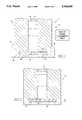
- FIG. 3ais a schematic representation showing a preferred embodiment of the apparatus for manipulating fluid flow.
- FIG. 3bis a schematic representation showing the apparatus for manipulating fluid flow having a collecting surface.
- FIG. 4is a schematic representation showing a preferred embodiment of the apparatus for manipulating fluid flow.
- FIG. 5is a schematic representation showing the restrictor disk with multiple openings.
- FIG. 6is a schematic representation showing a cross section of the restrictor.
- FIG. 1there is shown an apparatus 10 for manipulating fluid flow.
- the apparatus 10has a member 12 having a channel 14 through which fluid 16 flows and at least one opening 18 of a predetermined size in communication with the channel 14 which controls the flow of fluid 16.
- At least a portion 20 of the member 12is in thermal contact with the opening and is made of a material which is reactive with electromagnetic energy.
- the fluid 16is preferably a supercritical fluid such as CO 2 , water NH 3 , pentane, ethylene or freon.
- the fluid 16can be pressurized up to 700 atmospheres at temperatures up to 400° C.
- the means for providing electromagnetic energycan be any suitable device which causes the portion of the member in thermal contact with the opening to be heated non-invasively.
- a magnetroncan be used for providing microwave radiation or RF coils can be used for providing high frequency induction heating.
- the member 12includes a restrictor 24 having the opening 18 which is in thermal contact with the electromagnetically reactive portion 20.
- the restrictor 24is preferably a disk 64 made of a material having a low coefficient of thermal expansion and a high thermal conductivity such as ruby or sapphire.
- the disk 64can range in diameter between 0.4 to 50 mm or greater and can have a thickness of 0.1 to 0.5 mm or greater.
- the opening 18can range from 0.5 to 500 microns or greater.
- the member 12has an end 26 in which the restrictor 24 is fixedly disposed.
- the end 26is made of electromagnetically reactive material.
- the end 26includes a cap 28 which holds the restrictor 24 in place.
- the cap 28can be made of magnetically permeable material such as permalloy or of a microwave absorbing material such as silicon carbide. Alternatively, as shown in FIG. 2, the end can be crimped to define a pocket 30 which holds the restrictor in place.
- a gasket 70can be used to seal the restrictor 24 to the channel 14.
- the gasket 70can be made of teflon, vespel or other polymers.
- the apparatuscan include means 32 for collecting the fluid, such as a container 34.
- the container 34can hold a solvent 42 through which the fluid 16 is bubbled, thereby removing the analyte from the fluid 16.
- the solvent 42can be, for example, methanol, methylene chloride or hexane.
- the container 34 and surface 36can be made of glass, teflon or epoxy.
- the collecting means 32can be a collection surface 36. When the fluid is depressurized, the analytes are precipitated from the supercritical phase. The depressurized fluid and the precipitated analytes hit the collection surface and collect in the form of a dry powder.
- the means for providing electromagnetic energy 22 and the collection means 32are enclosed within an electromagnetic shield 36.
- the means for providing electromagnetic 22 energycan include a microwave generator or induction coils 40 as shown in FIG. 4.
- a temperature sensor 42is disposed adjacent to the electromagnetically reactive portion 20 of the member 12 for monitoring its temperature. The output of the temperature sensor 42 can be in communication with the means 22 for providing electromagnetic energy.
- the collecting means 32includes means for cooling the container 34 and a temperature sensor to monitor the container's temperature.
- the cooling meanscan use carbon dioxide or be a standard refrigeration system.
- the restrictor 24can have a plurality of openings 18 arranged in a radial pattern. The number and size of the openings determine the level of fluid restriction. Each opening 18 can be tapered to help prevent clogging.
- the present inventionalso relates to a method for manipulating the fluid flow.
- the methodcomprises the first step of heating with electromagnetic radiation at least a portion of a fluid restrictor; followed by the step of flowing fluid through the restrictor. Preferably, after the flowing step, there is the step of collecting the fluid.
- the present inventionis also related to an apparatus 50 for restricting fluid flow.
- the apparatus 50includes a member 52 having a first surface 54, a second surface 56 disposed in an opposing relationship with the first surface 54 and an opening 58 between the first and second surfaces for restricting fluid flow therethrough.
- the member 12is made of a material having a low coefficient of thermal expansion and high thermal conductivity, such as sapphire or ruby. The low coefficient of thermal expansion ensures that the opening essentially does not change in size much due to temperature variations, while the high thermal conductivity provides for efficient heat transfer.
- the opening 58has a first diameter 60 at the first surface 54 and a second diameter 62 at the second surface 54 wherein the first diameter is greater than the second diameter. This tapered profile helps to prevent clogging of the opening 58.
- the restrictoris a disk 64.
- the disk 64is drilled using a laser to form the opening 18.
- the disk materialhas the properties of low thermal expansion and high thermal conductivity.
- the disk 64is made of sapphire of 1 mm diameter and 0.25 mm thick having an opening 18 of 3 micron.
- the restrictor disk 64is mounted in a stainless steel tube 66 having a length of 60 mm. The disk 64 is held within the tube 66 with the cad 28.
- the diameter of the disk 64should be greater than the ID of the tube 66 and preferably not greater than the OD of the tube 66.
- the cap 28is also made of stainless steel.
- the 1 mm round and a 0.25 mm thick disk 64 with a 0.03 micron opening 18is mounted in a 1/16" O.D. tube 66 with a 0.020" ID by counterboring it to a depth of 0.25 mm.
- the cap 28 coated with silicon carbide with an outside diameter of 2.5 mm and an inside diameter of 1/16" and a height of 5 mmis fitted over the 1/16" tube to hold the disk 64.
- the cap 28is fitted by being pressed onto the 1/16" tube 28.
- a gasket 70is provided.
- the gasketis made a high temperature polymer such as teflon.
- the fluid 16 which is supercritical CO 2 pressurized to 700 atmospheres and having the preferred analyte dissolved withinflows through the channel 14 of member 12.
- the CO 2In order to exit the channel 14, the CO 2 must pass through the 3 micron opening 18 formed through the sapphire disk 64. This restriction causes a pressure loss within the CO 2 after passing through the opening 18. According to Boyle's law, this pressure loss is accompanied by a temperature drop within the CO 2 which can cause it to freeze, thus clogging the opening 18.
- Inductive coils 40surround the cap 28 and provide electromagnetic radiation which heat the silicon carbide coating of the cap 28.
- the sapphire disk 64which is in thermal contact with the cap 28 is in turn heated. In this manner, heat is supplied to the opening 18 to prevent the CO 2 from freezing and clogging the opening 18.
- a temperature sensormonitors the temperature of the cap 28 and/or disk 64.
- the CO 2is bubbled through a solvent of methylene chloride which collects the analyte from the CO 2 .
- a cooling systemis provided to prevent the methylene chloride from evaporating.
- a temperature sensoris disposed about the container 34 to monitor the temperature of the methylene chloride.
- the entire system of the container 34, the member 12 and the induction coils 40are enclosed in an electromagnetic shield 36 to prevent the electromagnetic radiation produced by the induction coils 70 from escaping.
- the analytesWhen the fluid is depressurized, the analytes are precipitated from the supercritical phase.
- the depressurized fluid and the precipitated analyteshit the collection surface and collect in the form of a dry powder.
- lowering the temperature of the collection surfaceimproves the efficiency of collection and reduces the probability of agglomeration of fine powders into lumps.
- the collection of an analyte in the form of a powdercan be achieved by replacing the container 34 with a passivated collection surface 36 which can be cooled, if necessary. After passing through the opening 18, the powder is collected on the surface 36.
Landscapes
- Physics & Mathematics (AREA)
- Chemical & Material Sciences (AREA)
- Analytical Chemistry (AREA)
- Electromagnetism (AREA)
- Health & Medical Sciences (AREA)
- Life Sciences & Earth Sciences (AREA)
- Chemical Kinetics & Catalysis (AREA)
- Biochemistry (AREA)
- General Health & Medical Sciences (AREA)
- General Physics & Mathematics (AREA)
- Immunology (AREA)
- Pathology (AREA)
- Sampling And Sample Adjustment (AREA)
- Physical Or Chemical Processes And Apparatus (AREA)
Abstract
Description
Claims (13)
Priority Applications (1)
| Application Number | Priority Date | Filing Date | Title |
|---|---|---|---|
| US07/800,572US5336869A (en) | 1991-11-27 | 1991-11-27 | Method and apparatus for manipulating fluid |
Applications Claiming Priority (1)
| Application Number | Priority Date | Filing Date | Title |
|---|---|---|---|
| US07/800,572US5336869A (en) | 1991-11-27 | 1991-11-27 | Method and apparatus for manipulating fluid |
Publications (1)
| Publication Number | Publication Date |
|---|---|
| US5336869Atrue US5336869A (en) | 1994-08-09 |
Family
ID=25178759
Family Applications (1)
| Application Number | Title | Priority Date | Filing Date |
|---|---|---|---|
| US07/800,572Expired - LifetimeUS5336869A (en) | 1991-11-27 | 1991-11-27 | Method and apparatus for manipulating fluid |
Country Status (1)
| Country | Link |
|---|---|
| US (1) | US5336869A (en) |
Cited By (12)
| Publication number | Priority date | Publication date | Assignee | Title |
|---|---|---|---|---|
| US5719380A (en)* | 1995-09-22 | 1998-02-17 | Eastman Kodak Company | Microwave heating apparatus for heating a flowing fluid |
| EP1092150A4 (en)* | 1998-07-01 | 2002-04-10 | Mt Systems Llc | Chromatographic column for microwave heating |
| WO2001037961A3 (en)* | 1999-11-10 | 2002-08-15 | Univ Holy Ghost Duquesne | Method for continuous processing of fluids using supercritical fluids and microwave energy |
| US20060006172A1 (en)* | 2004-07-09 | 2006-01-12 | Sedlmayr Steven R | Microwave fluid heating and distillation method |
| US20060006171A1 (en)* | 2004-07-09 | 2006-01-12 | Sedlmayr Steven R | Distillation and distillate method by microwaves |
| US20080150732A1 (en)* | 2006-12-22 | 2008-06-26 | Vigilan, Incorporated | Sensors and systems for detecting environmental conditions or changes |
| US20090134152A1 (en)* | 2005-10-27 | 2009-05-28 | Sedlmayr Steven R | Microwave nucleon-electron-bonding spin alignment and alteration of materials |
| US8502684B2 (en) | 2006-12-22 | 2013-08-06 | Geoffrey J. Bunza | Sensors and systems for detecting environmental conditions or changes |
| CN103987430A (en)* | 2012-02-15 | 2014-08-13 | 普拉兹马特罗尼卡新技术股份公司 | Method and device for distilling or thickening fluids |
| WO2014143419A1 (en) | 2013-03-12 | 2014-09-18 | Waters Technologies Corporation | Thermally modulated variable restrictor |
| WO2014189738A2 (en) | 2013-05-22 | 2014-11-27 | Waters Technologies Corporation | Thermally modulated variable restrictor for normalization of dynamic split ratios |
| US20160018367A1 (en)* | 2013-03-12 | 2016-01-21 | Waters Technologies Corporation | Matching thermally modulated variable restrictors to chromatography separation columns |
Citations (16)
| Publication number | Priority date | Publication date | Assignee | Title |
|---|---|---|---|---|
| US2978562A (en)* | 1958-05-19 | 1961-04-04 | Hubert D Fox | Instantaneous water heating system |
| US3778578A (en)* | 1971-11-10 | 1973-12-11 | R Long | Apparatus for producing super heated fluids |
| US3794801A (en)* | 1972-12-01 | 1974-02-26 | R Boles | Super heated vapor driven vehicle |
| US3920945A (en)* | 1974-04-24 | 1975-11-18 | Harold L Whitmer | Microwave fluid heater |
| US3999575A (en)* | 1975-10-28 | 1976-12-28 | General Motors Corporation | Control valve |
| US4358652A (en)* | 1978-12-21 | 1982-11-09 | Kaarup Darrell R | Fluid heater apparatus |
| US4417116A (en)* | 1981-09-02 | 1983-11-22 | Black Jerimiah B | Microwave water heating method and apparatus |
| US4434765A (en)* | 1981-10-30 | 1984-03-06 | Colt Industries Operating Corp. | Fuel injection apparatus and system |
| US4458721A (en)* | 1979-02-28 | 1984-07-10 | Brooklyn Union Gas Company | Pipeline flow restrictor |
| US4524743A (en)* | 1983-12-27 | 1985-06-25 | Colt Industries Operating Corp. | Fuel injection apparatus and system |
| US4627832A (en)* | 1984-05-08 | 1986-12-09 | Cordis Corporation | Three stage intracranial pressure relief valve having single-piece valve stem |
| US4741448A (en)* | 1987-06-02 | 1988-05-03 | Kenneth Ali Alley | Container with buoyant fluid flow restrictor |
| US4776838A (en)* | 1983-12-08 | 1988-10-11 | Cordis Corporation | Three stage valve |
| US5080128A (en)* | 1989-01-30 | 1992-01-14 | Taylor Julian S | Angle body restrictor valve |
| US5094753A (en)* | 1990-07-13 | 1992-03-10 | Isco, Inc. | Apparatus and method for supercritical fluid extraction |
| US5098690A (en)* | 1987-12-23 | 1992-03-24 | Uop | Method for distributing fluids in a downflow reactor |
- 1991
- 1991-11-27USUS07/800,572patent/US5336869A/ennot_activeExpired - Lifetime
Patent Citations (16)
| Publication number | Priority date | Publication date | Assignee | Title |
|---|---|---|---|---|
| US2978562A (en)* | 1958-05-19 | 1961-04-04 | Hubert D Fox | Instantaneous water heating system |
| US3778578A (en)* | 1971-11-10 | 1973-12-11 | R Long | Apparatus for producing super heated fluids |
| US3794801A (en)* | 1972-12-01 | 1974-02-26 | R Boles | Super heated vapor driven vehicle |
| US3920945A (en)* | 1974-04-24 | 1975-11-18 | Harold L Whitmer | Microwave fluid heater |
| US3999575A (en)* | 1975-10-28 | 1976-12-28 | General Motors Corporation | Control valve |
| US4358652A (en)* | 1978-12-21 | 1982-11-09 | Kaarup Darrell R | Fluid heater apparatus |
| US4458721A (en)* | 1979-02-28 | 1984-07-10 | Brooklyn Union Gas Company | Pipeline flow restrictor |
| US4417116A (en)* | 1981-09-02 | 1983-11-22 | Black Jerimiah B | Microwave water heating method and apparatus |
| US4434765A (en)* | 1981-10-30 | 1984-03-06 | Colt Industries Operating Corp. | Fuel injection apparatus and system |
| US4776838A (en)* | 1983-12-08 | 1988-10-11 | Cordis Corporation | Three stage valve |
| US4524743A (en)* | 1983-12-27 | 1985-06-25 | Colt Industries Operating Corp. | Fuel injection apparatus and system |
| US4627832A (en)* | 1984-05-08 | 1986-12-09 | Cordis Corporation | Three stage intracranial pressure relief valve having single-piece valve stem |
| US4741448A (en)* | 1987-06-02 | 1988-05-03 | Kenneth Ali Alley | Container with buoyant fluid flow restrictor |
| US5098690A (en)* | 1987-12-23 | 1992-03-24 | Uop | Method for distributing fluids in a downflow reactor |
| US5080128A (en)* | 1989-01-30 | 1992-01-14 | Taylor Julian S | Angle body restrictor valve |
| US5094753A (en)* | 1990-07-13 | 1992-03-10 | Isco, Inc. | Apparatus and method for supercritical fluid extraction |
Cited By (21)
| Publication number | Priority date | Publication date | Assignee | Title |
|---|---|---|---|---|
| US5719380A (en)* | 1995-09-22 | 1998-02-17 | Eastman Kodak Company | Microwave heating apparatus for heating a flowing fluid |
| EP1092150A4 (en)* | 1998-07-01 | 2002-04-10 | Mt Systems Llc | Chromatographic column for microwave heating |
| WO2001037961A3 (en)* | 1999-11-10 | 2002-08-15 | Univ Holy Ghost Duquesne | Method for continuous processing of fluids using supercritical fluids and microwave energy |
| US20060006172A1 (en)* | 2004-07-09 | 2006-01-12 | Sedlmayr Steven R | Microwave fluid heating and distillation method |
| US20060006171A1 (en)* | 2004-07-09 | 2006-01-12 | Sedlmayr Steven R | Distillation and distillate method by microwaves |
| US7119312B2 (en) | 2004-07-09 | 2006-10-10 | Sedlmayr Steven R | Microwave fluid heating and distillation method |
| US20060289502A1 (en)* | 2004-07-09 | 2006-12-28 | Sedlmayr Steven R | Microwave fluid heating and distillation method |
| US7432482B2 (en) | 2004-07-09 | 2008-10-07 | Sedlmayr Steven R | Distillation and distillate method by microwaves |
| US20090134152A1 (en)* | 2005-10-27 | 2009-05-28 | Sedlmayr Steven R | Microwave nucleon-electron-bonding spin alignment and alteration of materials |
| US7812731B2 (en) | 2006-12-22 | 2010-10-12 | Vigilan, Incorporated | Sensors and systems for detecting environmental conditions or changes |
| US20080150732A1 (en)* | 2006-12-22 | 2008-06-26 | Vigilan, Incorporated | Sensors and systems for detecting environmental conditions or changes |
| US8502684B2 (en) | 2006-12-22 | 2013-08-06 | Geoffrey J. Bunza | Sensors and systems for detecting environmental conditions or changes |
| CN103987430A (en)* | 2012-02-15 | 2014-08-13 | 普拉兹马特罗尼卡新技术股份公司 | Method and device for distilling or thickening fluids |
| CN103987430B (en)* | 2012-02-15 | 2016-08-10 | 普拉兹马特罗尼卡新技术股份公司 | For the method and apparatus distilled or make liquid thickening |
| WO2014143419A1 (en) | 2013-03-12 | 2014-09-18 | Waters Technologies Corporation | Thermally modulated variable restrictor |
| US20160018367A1 (en)* | 2013-03-12 | 2016-01-21 | Waters Technologies Corporation | Matching thermally modulated variable restrictors to chromatography separation columns |
| EP2972291A4 (en)* | 2013-03-12 | 2016-10-26 | Waters Technologies Corp | Thermally modulated variable restrictor |
| US11733216B2 (en) | 2013-03-12 | 2023-08-22 | Waters Technologies Corporation | Matching thermally modulated variable restrictors to chromatography separation columns |
| WO2014189738A2 (en) | 2013-05-22 | 2014-11-27 | Waters Technologies Corporation | Thermally modulated variable restrictor for normalization of dynamic split ratios |
| EP2999961A4 (en)* | 2013-05-22 | 2016-12-28 | Waters Technologies Corp | THERMALLY MODIFIED VARIABLE LIMITER FOR DYNAMIC DIVISION REPORTING STANDARDIZATION |
| US10006890B2 (en) | 2013-05-22 | 2018-06-26 | Waters Technologies Corporation | Thermally modulated variable restrictor for normalization of dynamic split ratios |
Similar Documents
| Publication | Publication Date | Title |
|---|---|---|
| US5336869A (en) | Method and apparatus for manipulating fluid | |
| US6054693A (en) | Microwave technique for brazing materials | |
| US5316262A (en) | Fluid restrictor apparatus and method for making the same | |
| Keene | Review of data for the surface tension of pure metals | |
| US5151178A (en) | Axially-driven valve controlled trapping assembly | |
| Kuznetsov | Influence of the stress jump condition at the porous-medium/clear-fluid interface on a flow at a porous wall | |
| US5647228A (en) | Apparatus and method for regulating temperature in a cryogenic test chamber | |
| WO1998032312A9 (en) | Microwave technique for brazing materials | |
| US4892654A (en) | Trapping assembly | |
| Schonherr et al. | Electrical and thermodynamic properties of mercury in the metal-semiconductor transition range | |
| JP2007512517A (en) | Liquid flow sensing thermal interface method and system | |
| Kyung et al. | Periodic flow excursion in an open two-phase natural circulation loop | |
| Borisov et al. | Nuclear magnetic resonance and acoustic investigations of the melting-freezing phase transition of gallium in a porous glass | |
| Dahm et al. | Relaxation time and effective mass of ions in liquid helium | |
| US4556318A (en) | Spectrochemical analysis | |
| US20060053807A1 (en) | Freeze-thaw valve that self-limits cryogenic agent usage | |
| CA1328925C (en) | Process of continuous casting with detection of possibility of break out | |
| WO2004066347A2 (en) | Device for producing electroconductive passages in a semiconductor wafer by means of thermomigration | |
| Liebermann | Planar and cylindrical jet streaming of water and of molten Fe40Ni40B20 alloy | |
| CN109564120A (en) | Method for the sensor of heat flow measuring device, heat flow measuring device and the sensor for manufacturing heat flow measuring device | |
| Hoffmann et al. | Measurements of attenuation of third sound: Evidence of trapped vorticity in thick films of superfluid 4He | |
| JP4537270B2 (en) | Cryostat for superconducting magnet | |
| Mishima et al. | Dielectric relaxation of 4: 1 v/v methanol–ethanol to 90 kbar | |
| WO1999027407A1 (en) | Temperature control for microscopy | |
| Giordano | Experimental study of the flow of liquid He 4 through very small channels: Finite-size effects near T λ |
Legal Events
| Date | Code | Title | Description |
|---|---|---|---|
| STCF | Information on status: patent grant | Free format text:PATENTED CASE | |
| FPAY | Fee payment | Year of fee payment:4 | |
| SULP | Surcharge for late payment | ||
| FPAY | Fee payment | Year of fee payment:8 | |
| REMI | Maintenance fee reminder mailed | ||
| REMI | Maintenance fee reminder mailed | ||
| FPAY | Fee payment | Year of fee payment:12 | |
| SULP | Surcharge for late payment | Year of fee payment:11 | |
| AS | Assignment | Owner name:THAR TECHNOLOGIES, INC., PENNSYLVANIA Free format text:ASSIGNMENT OF ASSIGNORS INTEREST;ASSIGNOR:CHORDIA, LALIT M. (FORMERLY LALITH M. KUMAR);REEL/FRAME:019520/0509 Effective date:20070628 | |
| AS | Assignment | Owner name:THAR INSTRUMENTS, INC., PENNSYLVANIA Free format text:ASSIGNMENT OF ASSIGNORS INTEREST;ASSIGNOR:THAR TECHNOLOGIES, INC.;REEL/FRAME:019529/0761 Effective date:20070703 | |
| AS | Assignment | Owner name:NATIONAL CITY BANK, PENNSYLVANIA Free format text:SECURITY AGREEMENT;ASSIGNOR:THAR INSTRUMENTS, INC.;REEL/FRAME:019550/0131 Effective date:20070703 Owner name:NATIONAL CITY BANK,PENNSYLVANIA Free format text:SECURITY AGREEMENT;ASSIGNOR:THAR INSTRUMENTS, INC.;REEL/FRAME:019550/0131 Effective date:20070703 | |
| AS | Assignment | Owner name:THAR INSTRUMENTS, INC., PENNSYLVANIA Free format text:ASSIGNMENT OF ASSIGNORS INTEREST;ASSIGNOR:NATIONAL CITY BANK OF PITTSBURGH;REEL/FRAME:022835/0147 Effective date:20090611 Owner name:THAR INSTRUMENTS, INC.,PENNSYLVANIA Free format text:ASSIGNMENT OF ASSIGNORS INTEREST;ASSIGNOR:NATIONAL CITY BANK OF PITTSBURGH;REEL/FRAME:022835/0147 Effective date:20090611 | |
| AS | Assignment | Owner name:WATERS TECHNOLOGIES CORPORATION, MASSACHUSETTS Free format text:MERGER;ASSIGNOR:THAR INSTRUMENTS INC.;REEL/FRAME:028021/0088 Effective date:20100303 |