US5336188A - Fluid delivery apparatus having a stored energy source - Google Patents
Fluid delivery apparatus having a stored energy sourceDownload PDFInfo
- Publication number
- US5336188A US5336188AUS08/069,937US6993793AUS5336188AUS 5336188 AUS5336188 AUS 5336188AUS 6993793 AUS6993793 AUS 6993793AUS 5336188 AUS5336188 AUS 5336188A
- Authority
- US
- United States
- Prior art keywords
- base
- fluid
- membrane
- portions
- chamber
- Prior art date
- Legal status (The legal status is an assumption and is not a legal conclusion. Google has not performed a legal analysis and makes no representation as to the accuracy of the status listed.)
- Expired - Fee Related
Links
- 239000012530fluidSubstances0.000titleclaimsabstractdescription207
- 239000012528membraneSubstances0.000claimsabstractdescription129
- 239000000654additiveSubstances0.000claimsdescription20
- 230000000996additive effectEffects0.000claimsdescription19
- 239000007788liquidSubstances0.000claimsdescription15
- 239000003085diluting agentSubstances0.000claimsdescription8
- 238000007789sealingMethods0.000claimsdescription4
- 239000000758substrateSubstances0.000claimsdescription4
- 238000010276constructionMethods0.000abstractdescription25
- 230000004888barrier functionEffects0.000abstractdescription19
- 230000001413cellular effectEffects0.000abstractdescription9
- 239000003795chemical substances by applicationSubstances0.000description14
- 239000003814drugSubstances0.000description13
- 238000001802infusionMethods0.000description12
- 239000006260foamSubstances0.000description11
- 230000007246mechanismEffects0.000description10
- 239000000853adhesiveSubstances0.000description9
- 230000001070adhesive effectEffects0.000description9
- 239000000463materialSubstances0.000description9
- 239000012815thermoplastic materialSubstances0.000description9
- 230000009286beneficial effectEffects0.000description7
- 238000013022ventingMethods0.000description5
- 210000001015abdomenAnatomy0.000description4
- 239000007789gasSubstances0.000description4
- 210000003734kidneyAnatomy0.000description4
- 230000000712assemblyEffects0.000description3
- 238000000429assemblyMethods0.000description3
- 230000001276controlling effectEffects0.000description3
- 238000013461designMethods0.000description3
- 229940079593drugDrugs0.000description3
- 230000036512infertilityEffects0.000description3
- 238000000034methodMethods0.000description3
- 230000009471actionEffects0.000description2
- 239000013043chemical agentSubstances0.000description2
- 230000000994depressogenic effectEffects0.000description2
- 230000000694effectsEffects0.000description2
- 238000010828elutionMethods0.000description2
- 238000001990intravenous administrationMethods0.000description2
- 238000012986modificationMethods0.000description2
- 230000004048modificationEffects0.000description2
- 239000002831pharmacologic agentSubstances0.000description2
- 239000004033plasticSubstances0.000description2
- 230000001225therapeutic effectEffects0.000description2
- 102000004190EnzymesHuman genes0.000description1
- 108090000790EnzymesProteins0.000description1
- 229940035676analgesicsDrugs0.000description1
- 210000003484anatomyAnatomy0.000description1
- 239000000730antalgic agentSubstances0.000description1
- 239000003242anti bacterial agentSubstances0.000description1
- 229940088710antibiotic agentDrugs0.000description1
- 239000011324beadSubstances0.000description1
- 230000023555blood coagulationEffects0.000description1
- 230000015556catabolic processEffects0.000description1
- 230000003197catalytic effectEffects0.000description1
- 229910052729chemical elementInorganic materials0.000description1
- 238000002512chemotherapyMethods0.000description1
- 238000006731degradation reactionMethods0.000description1
- 210000002249digestive systemAnatomy0.000description1
- 229920001971elastomerPolymers0.000description1
- 239000000806elastomerSubstances0.000description1
- 239000006263elastomeric foamSubstances0.000description1
- 238000011010flushing procedureMethods0.000description1
- 210000001035gastrointestinal tractAnatomy0.000description1
- 239000011521glassSubstances0.000description1
- 230000005484gravityEffects0.000description1
- 230000036541healthEffects0.000description1
- 239000005556hormoneSubstances0.000description1
- 229940088597hormoneDrugs0.000description1
- 230000002209hydrophobic effectEffects0.000description1
- 238000007373indentationMethods0.000description1
- 238000002347injectionMethods0.000description1
- 239000007924injectionSubstances0.000description1
- 210000004185liverAnatomy0.000description1
- 230000007257malfunctionEffects0.000description1
- 238000004519manufacturing processMethods0.000description1
- 230000013011matingEffects0.000description1
- 238000002483medicationMethods0.000description1
- 239000000203mixtureSubstances0.000description1
- 238000012544monitoring processMethods0.000description1
- 230000000737periodic effectEffects0.000description1
- 235000020030perryNutrition0.000description1
- 230000003389potentiating effectEffects0.000description1
- 230000002035prolonged effectEffects0.000description1
- 230000001105regulatory effectEffects0.000description1
- 150000003431steroidsChemical class0.000description1
- 231100000331toxicToxicity0.000description1
- 230000002588toxic effectEffects0.000description1
- 210000003462veinAnatomy0.000description1
- 238000005406washingMethods0.000description1
- 238000003466weldingMethods0.000description1
Images


Classifications
- A—HUMAN NECESSITIES
- A61—MEDICAL OR VETERINARY SCIENCE; HYGIENE
- A61M—DEVICES FOR INTRODUCING MEDIA INTO, OR ONTO, THE BODY; DEVICES FOR TRANSDUCING BODY MEDIA OR FOR TAKING MEDIA FROM THE BODY; DEVICES FOR PRODUCING OR ENDING SLEEP OR STUPOR
- A61M5/00—Devices for bringing media into the body in a subcutaneous, intra-vascular or intramuscular way; Accessories therefor, e.g. filling or cleaning devices, arm-rests
- A61M5/14—Infusion devices, e.g. infusing by gravity; Blood infusion; Accessories therefor
- A61M5/1407—Infusion of two or more substances
- A61M5/1409—Infusion of two or more substances in series, e.g. first substance passing through container holding second substance, e.g. reconstitution systems
- A—HUMAN NECESSITIES
- A61—MEDICAL OR VETERINARY SCIENCE; HYGIENE
- A61M—DEVICES FOR INTRODUCING MEDIA INTO, OR ONTO, THE BODY; DEVICES FOR TRANSDUCING BODY MEDIA OR FOR TAKING MEDIA FROM THE BODY; DEVICES FOR PRODUCING OR ENDING SLEEP OR STUPOR
- A61M5/00—Devices for bringing media into the body in a subcutaneous, intra-vascular or intramuscular way; Accessories therefor, e.g. filling or cleaning devices, arm-rests
- A61M5/14—Infusion devices, e.g. infusing by gravity; Blood infusion; Accessories therefor
- A61M5/142—Pressure infusion, e.g. using pumps
- A61M5/145—Pressure infusion, e.g. using pumps using pressurised reservoirs, e.g. pressurised by means of pistons
- A61M5/148—Pressure infusion, e.g. using pumps using pressurised reservoirs, e.g. pressurised by means of pistons flexible, e.g. independent bags
- A61M5/152—Pressure infusion, e.g. using pumps using pressurised reservoirs, e.g. pressurised by means of pistons flexible, e.g. independent bags pressurised by contraction of elastic reservoirs
- A—HUMAN NECESSITIES
- A61—MEDICAL OR VETERINARY SCIENCE; HYGIENE
- A61J—CONTAINERS SPECIALLY ADAPTED FOR MEDICAL OR PHARMACEUTICAL PURPOSES; DEVICES OR METHODS SPECIALLY ADAPTED FOR BRINGING PHARMACEUTICAL PRODUCTS INTO PARTICULAR PHYSICAL OR ADMINISTERING FORMS; DEVICES FOR ADMINISTERING FOOD OR MEDICINES ORALLY; BABY COMFORTERS; DEVICES FOR RECEIVING SPITTLE
- A61J1/00—Containers specially adapted for medical or pharmaceutical purposes
- A61J1/14—Details; Accessories therefor
- A61J1/20—Arrangements for transferring or mixing fluids, e.g. from vial to syringe
- A61J1/2003—Accessories used in combination with means for transfer or mixing of fluids, e.g. for activating fluid flow, separating fluids, filtering fluid or venting
- A61J1/2006—Piercing means
- A61J1/201—Piercing means having one piercing end
- A—HUMAN NECESSITIES
- A61—MEDICAL OR VETERINARY SCIENCE; HYGIENE
- A61J—CONTAINERS SPECIALLY ADAPTED FOR MEDICAL OR PHARMACEUTICAL PURPOSES; DEVICES OR METHODS SPECIALLY ADAPTED FOR BRINGING PHARMACEUTICAL PRODUCTS INTO PARTICULAR PHYSICAL OR ADMINISTERING FORMS; DEVICES FOR ADMINISTERING FOOD OR MEDICINES ORALLY; BABY COMFORTERS; DEVICES FOR RECEIVING SPITTLE
- A61J1/00—Containers specially adapted for medical or pharmaceutical purposes
- A61J1/14—Details; Accessories therefor
- A61J1/20—Arrangements for transferring or mixing fluids, e.g. from vial to syringe
- A61J1/2003—Accessories used in combination with means for transfer or mixing of fluids, e.g. for activating fluid flow, separating fluids, filtering fluid or venting
- A61J1/2068—Venting means
- A61J1/2075—Venting means for external venting
- A—HUMAN NECESSITIES
- A61—MEDICAL OR VETERINARY SCIENCE; HYGIENE
- A61J—CONTAINERS SPECIALLY ADAPTED FOR MEDICAL OR PHARMACEUTICAL PURPOSES; DEVICES OR METHODS SPECIALLY ADAPTED FOR BRINGING PHARMACEUTICAL PRODUCTS INTO PARTICULAR PHYSICAL OR ADMINISTERING FORMS; DEVICES FOR ADMINISTERING FOOD OR MEDICINES ORALLY; BABY COMFORTERS; DEVICES FOR RECEIVING SPITTLE
- A61J1/00—Containers specially adapted for medical or pharmaceutical purposes
- A61J1/14—Details; Accessories therefor
- A61J1/20—Arrangements for transferring or mixing fluids, e.g. from vial to syringe
- A61J1/2003—Accessories used in combination with means for transfer or mixing of fluids, e.g. for activating fluid flow, separating fluids, filtering fluid or venting
- A61J1/2079—Filtering means
- A61J1/2082—Filtering means for gas filtration
- A—HUMAN NECESSITIES
- A61—MEDICAL OR VETERINARY SCIENCE; HYGIENE
- A61J—CONTAINERS SPECIALLY ADAPTED FOR MEDICAL OR PHARMACEUTICAL PURPOSES; DEVICES OR METHODS SPECIALLY ADAPTED FOR BRINGING PHARMACEUTICAL PRODUCTS INTO PARTICULAR PHYSICAL OR ADMINISTERING FORMS; DEVICES FOR ADMINISTERING FOOD OR MEDICINES ORALLY; BABY COMFORTERS; DEVICES FOR RECEIVING SPITTLE
- A61J1/00—Containers specially adapted for medical or pharmaceutical purposes
- A61J1/14—Details; Accessories therefor
- A61J1/20—Arrangements for transferring or mixing fluids, e.g. from vial to syringe
- A61J1/2096—Combination of a vial and a syringe for transferring or mixing their contents
- A—HUMAN NECESSITIES
- A61—MEDICAL OR VETERINARY SCIENCE; HYGIENE
- A61M—DEVICES FOR INTRODUCING MEDIA INTO, OR ONTO, THE BODY; DEVICES FOR TRANSDUCING BODY MEDIA OR FOR TAKING MEDIA FROM THE BODY; DEVICES FOR PRODUCING OR ENDING SLEEP OR STUPOR
- A61M2205/00—General characteristics of the apparatus
- A61M2205/19—Constructional features of carpules, syringes or blisters
- A61M2205/192—Avoiding coring, e.g. preventing formation of particles during puncture
- A61M2205/197—Avoiding coring, e.g. preventing formation of particles during puncture by the seal material
- A—HUMAN NECESSITIES
- A61—MEDICAL OR VETERINARY SCIENCE; HYGIENE
- A61M—DEVICES FOR INTRODUCING MEDIA INTO, OR ONTO, THE BODY; DEVICES FOR TRANSDUCING BODY MEDIA OR FOR TAKING MEDIA FROM THE BODY; DEVICES FOR PRODUCING OR ENDING SLEEP OR STUPOR
- A61M2209/00—Ancillary equipment
- A61M2209/04—Tools for specific apparatus
- A61M2209/045—Tools for specific apparatus for filling, e.g. for filling reservoirs
- A—HUMAN NECESSITIES
- A61—MEDICAL OR VETERINARY SCIENCE; HYGIENE
- A61M—DEVICES FOR INTRODUCING MEDIA INTO, OR ONTO, THE BODY; DEVICES FOR TRANSDUCING BODY MEDIA OR FOR TAKING MEDIA FROM THE BODY; DEVICES FOR PRODUCING OR ENDING SLEEP OR STUPOR
- A61M5/00—Devices for bringing media into the body in a subcutaneous, intra-vascular or intramuscular way; Accessories therefor, e.g. filling or cleaning devices, arm-rests
- A61M5/14—Infusion devices, e.g. infusing by gravity; Blood infusion; Accessories therefor
- A61M5/1407—Infusion of two or more substances
- A—HUMAN NECESSITIES
- A61—MEDICAL OR VETERINARY SCIENCE; HYGIENE
- A61M—DEVICES FOR INTRODUCING MEDIA INTO, OR ONTO, THE BODY; DEVICES FOR TRANSDUCING BODY MEDIA OR FOR TAKING MEDIA FROM THE BODY; DEVICES FOR PRODUCING OR ENDING SLEEP OR STUPOR
- A61M5/00—Devices for bringing media into the body in a subcutaneous, intra-vascular or intramuscular way; Accessories therefor, e.g. filling or cleaning devices, arm-rests
- A61M5/14—Infusion devices, e.g. infusing by gravity; Blood infusion; Accessories therefor
- A61M5/142—Pressure infusion, e.g. using pumps
- A61M5/14244—Pressure infusion, e.g. using pumps adapted to be carried by the patient, e.g. portable on the body
- A61M5/14248—Pressure infusion, e.g. using pumps adapted to be carried by the patient, e.g. portable on the body of the skin patch type
- Y—GENERAL TAGGING OF NEW TECHNOLOGICAL DEVELOPMENTS; GENERAL TAGGING OF CROSS-SECTIONAL TECHNOLOGIES SPANNING OVER SEVERAL SECTIONS OF THE IPC; TECHNICAL SUBJECTS COVERED BY FORMER USPC CROSS-REFERENCE ART COLLECTIONS [XRACs] AND DIGESTS
- Y10—TECHNICAL SUBJECTS COVERED BY FORMER USPC
- Y10S—TECHNICAL SUBJECTS COVERED BY FORMER USPC CROSS-REFERENCE ART COLLECTIONS [XRACs] AND DIGESTS
- Y10S128/00—Surgery
- Y10S128/12—Pressure infusion
Definitions
- Membrane 77can be specifically tailored so as to provide differential stresses and differential areas of stored energy densities as between reservoirs R-1 and R-2 and thereby enabling fluid flow between the reservoirs. Initially fluid cannot flow between reservoirs R-1 and R-2 because of the closure means which is here provided in the form of the deformable wall section 79c of cover 79.
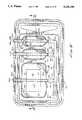
- distendable membrane 422will be distended from the first position wherein it is proximate the base to the second position shown in FIGS. 36 and 37 wherein it cooperates with the base to define the three reservoirs of this form of the invention.
- the various septal portsare normally covered by removable caps "C".
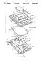
- containers 416are telescopically receivable with one of chambers 414b or 414c in the manner shown in FIG. 35.
- each chamber 416ais closed by a penetrable piston 456 which is telescopically movable within chamber 416a from a first forward position to a rearward position proximate the closed end of container 416.
- Piston 456is provided with a plurality of circumferentially extending sealing beads 456a which sealably engage the inner walls 416a of container 416 as the piston moves rearwardly.
Landscapes
- Health & Medical Sciences (AREA)
- Vascular Medicine (AREA)
- Engineering & Computer Science (AREA)
- Anesthesiology (AREA)
- Biomedical Technology (AREA)
- Heart & Thoracic Surgery (AREA)
- Hematology (AREA)
- Life Sciences & Earth Sciences (AREA)
- Animal Behavior & Ethology (AREA)
- General Health & Medical Sciences (AREA)
- Public Health (AREA)
- Veterinary Medicine (AREA)
- Infusion, Injection, And Reservoir Apparatuses (AREA)
- Feeding, Discharge, Calcimining, Fusing, And Gas-Generation Devices (AREA)
- Media Introduction/Drainage Providing Device (AREA)
Abstract
Description
Claims (14)
Priority Applications (22)
| Application Number | Priority Date | Filing Date | Title |
|---|---|---|---|
| US08/069,937US5336188A (en) | 1989-06-16 | 1993-05-28 | Fluid delivery apparatus having a stored energy source |
| US08/129,693US5419771A (en) | 1989-06-16 | 1993-09-29 | Fluid delivery apparatus and support assembly |
| US08/129,470US5374256A (en) | 1989-06-16 | 1993-09-29 | Fluid container for use with a fluid delivery apparatus |
| US08/192,035US5468226A (en) | 1989-06-16 | 1994-02-03 | Fluid delivery apparatus having a stored energy source |
| RU95122702ARU2136326C1 (en) | 1993-05-28 | 1994-05-17 | Liquid supply device |
| AU69513/94AAU694432B2 (en) | 1993-05-28 | 1994-05-17 | Fluid delivery apparatus |
| CA 2163997CA2163997A1 (en) | 1993-05-28 | 1994-05-17 | Fluid delivery apparatus |
| PCT/US1994/005475WO1994027669A1 (en) | 1993-05-28 | 1994-05-17 | Fluid delivery apparatus |
| CN94192805ACN1127478A (en) | 1993-05-28 | 1994-05-17 | Infusion equipment |
| JP50074195AJPH09500291A (en) | 1993-05-28 | 1994-05-17 | Fluid supply device |
| BR9406694ABR9406694A (en) | 1993-05-28 | 1994-05-17 | Fluid release device |
| EP94918006AEP0702578A4 (en) | 1993-05-28 | 1994-05-17 | Fluid delivery apparatus |
| US08/269,445US5569236A (en) | 1989-06-16 | 1994-06-30 | Fluid delivery apparatus |
| US08/271,209US5492533A (en) | 1989-06-16 | 1994-07-01 | Fluid delivery apparatus |
| US08/349,404US5545139A (en) | 1989-06-16 | 1994-12-02 | Fluid container for use with a fluid delivery apparatus |
| US08/451,520US5656032A (en) | 1989-06-16 | 1995-05-26 | Fluid delivery apparatus and method of making same |
| US08/540,914US5716343A (en) | 1989-06-16 | 1995-10-11 | Fluid delivery apparatus |
| US08/575,345US5693019A (en) | 1989-06-16 | 1995-12-20 | Fluid delivery apparatus |
| US08/576,513US5720729A (en) | 1989-06-16 | 1995-12-21 | Fluid delivery apparatus |
| US08/907,564US5906592A (en) | 1989-06-16 | 1997-08-08 | Fluid delivery apparatus |
| US08/991,928US6068613A (en) | 1989-06-16 | 1997-12-16 | Fluid delivery device |
| AU68084/98AAU700421B2 (en) | 1993-05-28 | 1998-05-25 | Fluid delivery apparatus |
Applications Claiming Priority (6)
| Application Number | Priority Date | Filing Date | Title |
|---|---|---|---|
| US07/367,304US5019047A (en) | 1989-06-16 | 1989-06-16 | Fluid delivery apparatus |
| US07/642,208US5169389A (en) | 1989-06-16 | 1991-01-16 | Fluid delivery apparatus |
| US07/870,269US5205820A (en) | 1989-06-16 | 1992-04-17 | Fluid delivery apparatus |
| US07/987,021US5279558A (en) | 1989-06-16 | 1992-12-07 | Fluid delivery apparatus with an additive |
| US4643893A | 1993-05-18 | 1993-05-18 | |
| US08/069,937US5336188A (en) | 1989-06-16 | 1993-05-28 | Fluid delivery apparatus having a stored energy source |
Related Parent Applications (1)
| Application Number | Title | Priority Date | Filing Date |
|---|---|---|---|
| US4643893AContinuation-In-Part | 1989-06-16 | 1993-05-18 |
Related Child Applications (4)
| Application Number | Title | Priority Date | Filing Date |
|---|---|---|---|
| US08/129,470Continuation-In-PartUS5374256A (en) | 1989-06-16 | 1993-09-29 | Fluid container for use with a fluid delivery apparatus |
| US08/129,693Continuation-In-PartUS5419771A (en) | 1989-06-16 | 1993-09-29 | Fluid delivery apparatus and support assembly |
| US08/192,035DivisionUS5468226A (en) | 1989-06-16 | 1994-02-03 | Fluid delivery apparatus having a stored energy source |
| US08/271,209DivisionUS5492533A (en) | 1989-06-16 | 1994-07-01 | Fluid delivery apparatus |
Publications (1)
| Publication Number | Publication Date |
|---|---|
| US5336188Atrue US5336188A (en) | 1994-08-09 |
Family
ID=22092129
Family Applications (4)
| Application Number | Title | Priority Date | Filing Date |
|---|---|---|---|
| US08/069,937Expired - Fee RelatedUS5336188A (en) | 1989-06-16 | 1993-05-28 | Fluid delivery apparatus having a stored energy source |
| US08/192,035Expired - Fee RelatedUS5468226A (en) | 1989-06-16 | 1994-02-03 | Fluid delivery apparatus having a stored energy source |
| US08/271,209Expired - Fee RelatedUS5492533A (en) | 1989-06-16 | 1994-07-01 | Fluid delivery apparatus |
| US08/575,345Expired - Fee RelatedUS5693019A (en) | 1989-06-16 | 1995-12-20 | Fluid delivery apparatus |
Family Applications After (3)
| Application Number | Title | Priority Date | Filing Date |
|---|---|---|---|
| US08/192,035Expired - Fee RelatedUS5468226A (en) | 1989-06-16 | 1994-02-03 | Fluid delivery apparatus having a stored energy source |
| US08/271,209Expired - Fee RelatedUS5492533A (en) | 1989-06-16 | 1994-07-01 | Fluid delivery apparatus |
| US08/575,345Expired - Fee RelatedUS5693019A (en) | 1989-06-16 | 1995-12-20 | Fluid delivery apparatus |
Country Status (9)
| Country | Link |
|---|---|
| US (4) | US5336188A (en) |
| EP (1) | EP0702578A4 (en) |
| JP (1) | JPH09500291A (en) |
| CN (1) | CN1127478A (en) |
| AU (1) | AU694432B2 (en) |
| BR (1) | BR9406694A (en) |
| CA (1) | CA2163997A1 (en) |
| RU (1) | RU2136326C1 (en) |
| WO (1) | WO1994027669A1 (en) |
Cited By (54)
| Publication number | Priority date | Publication date | Assignee | Title |
|---|---|---|---|---|
| US5417667A (en)* | 1993-04-19 | 1995-05-23 | Hyprotek, Inc. | Catheter access system and method |
| WO1996004038A1 (en)* | 1994-08-02 | 1996-02-15 | Science Incorporated | Closed drug delivery system |
| WO1997013544A1 (en)* | 1995-10-11 | 1997-04-17 | Science Incorporated | Fluid delivery device with bolus injection site |
| US5700244A (en)* | 1992-04-17 | 1997-12-23 | Science Incorporated | Fluid dispenser with fill adapter |
| US5741242A (en)* | 1995-12-22 | 1998-04-21 | Science Incorporated | Infusion device with fill assembly |
| US5776105A (en)* | 1995-09-28 | 1998-07-07 | Children's Medical Center Corp. | Ambulatory intravenous fluid holder |
| US5807335A (en)* | 1995-12-22 | 1998-09-15 | Science Incorporated | Fluid delivery device with conformable ullage and fill assembly |
| US5814020A (en)* | 1995-09-11 | 1998-09-29 | Elan Medical Technlogies Limited | Medicament delivery device |
| US5830187A (en)* | 1995-12-22 | 1998-11-03 | Science Incorporated | Fluid delivery device with conformable ullage and fill assembly |
| US5840071A (en)* | 1996-12-18 | 1998-11-24 | Science Incorporated | Fluid delivery apparatus with flow indicator and vial fill |
| EP0781147A4 (en)* | 1994-09-16 | 1998-11-25 | River Medical Inc | Apparatus and methods for multiple fluid infusion |
| US5876377A (en)* | 1994-12-02 | 1999-03-02 | Science Incorporated | Medicament dispenser |
| US5957895A (en) | 1998-02-20 | 1999-09-28 | Becton Dickinson And Company | Low-profile automatic injection device with self-emptying reservoir |
| EP0833678A4 (en)* | 1995-05-26 | 2000-05-03 | Science Inc | Fluid delivery apparatus |
| US6355024B1 (en)* | 1999-07-14 | 2002-03-12 | Mallinckrodt Inc. | Medical fluid delivery system |
| US6395012B1 (en) | 2000-05-04 | 2002-05-28 | Inbae Yoon | Apparatus and method for delivering and deploying an expandable body member in a uterine cavity |
| US20040116847A1 (en)* | 2002-09-12 | 2004-06-17 | Children's Hospital Medical Center | Method and device for painless injection of medication |
| US20050033232A1 (en)* | 2003-08-05 | 2005-02-10 | Kriesel Marshall S. | Infusion apparatus with modulated flow control |
| US20050033233A1 (en)* | 2003-08-04 | 2005-02-10 | Kriesel Marshall S. | Infusion apparatus with constant force spring energy source |
| US20050038387A1 (en)* | 2003-08-04 | 2005-02-17 | Kriesel Marshall S. | Multichannel fluid delivery device |
| US20050171477A1 (en)* | 2002-05-23 | 2005-08-04 | Seedlings Life Science Ventures | Apparatus and method for rapid auto-injection of medication |
| US6953450B2 (en) | 2002-08-22 | 2005-10-11 | Baxa Corporation | Apparatus and method for administration of IV liquid medication and IV flush solutions |
| US20050263615A1 (en)* | 2004-05-26 | 2005-12-01 | Kriesel Marshall S | Fluid delivery apparatus with adjustable flow rate control |
| US20050277882A1 (en)* | 2004-05-26 | 2005-12-15 | Kriesel Marshall S | Infusion apparatus |
| US20050277883A1 (en)* | 2004-05-26 | 2005-12-15 | Kriesel Marshall S | Fluid delivery device |
| US20050277884A1 (en)* | 2004-05-26 | 2005-12-15 | Kriesel Marshall S | Fluid delivery apparatus with bellows reservoir |
| US20060195057A1 (en)* | 2005-02-18 | 2006-08-31 | Kriesel Marshall S | Fluid delivery apparatus with vial fill |
| US20060196552A1 (en)* | 2005-02-17 | 2006-09-07 | Kriesel Marshall S | Distal rate control device |
| US20060206052A1 (en)* | 2005-02-15 | 2006-09-14 | Kriesel Marshall S | Fluid delivery and mixing apparatus with flow rate control |
| US20070088282A1 (en)* | 2005-10-03 | 2007-04-19 | Joseph Ranalletta | Apparatus, method and system for administration of IV liquid medication and IV flush solutions |
| US20070156090A1 (en)* | 2004-05-26 | 2007-07-05 | Kriesel Marshall S | Fluid delivery apparatus |
| US20070219501A1 (en)* | 2006-03-15 | 2007-09-20 | Kriesel Marshall S | Fluid dispensing apparatus |
| US20070276320A1 (en)* | 2004-02-17 | 2007-11-29 | Wall Eric J | Injection Device for Administering a Vaccine |
| US20080009835A1 (en)* | 2005-02-17 | 2008-01-10 | Kriesel Marshall S | Fluid dispensing apparatus with flow rate control |
| US20080027376A1 (en)* | 2006-07-31 | 2008-01-31 | Kriesel Marshall S | Fluid dispensing device with additive |
| US20080125721A1 (en)* | 2006-07-12 | 2008-05-29 | Mobius Therapeutics, Inc. | Apparatus and method for reconstituting a pharmaceutical and preparing the reconstituted pharmaceutical for transient application |
| US20080243077A1 (en)* | 2007-04-02 | 2008-10-02 | Bivin Donald B | Fluid dispenser with uniformly collapsible reservoir |
| USD579542S1 (en) | 2006-06-09 | 2008-10-28 | Baxa Corporation | Medical liquid administration device |
| US20080319385A1 (en)* | 2007-06-25 | 2008-12-25 | Kriesel Marshall S | Fluid dispenser with additive sub-system |
| US20090024083A1 (en)* | 2007-06-25 | 2009-01-22 | Kriesel Marshall S | Fluid dispenser with additive sub-system |
| US20090163860A1 (en)* | 2007-12-21 | 2009-06-25 | Carticept Medical Inc. | Handpiece assembly for articular injection systems |
| US7828772B2 (en) | 2006-03-15 | 2010-11-09 | Bioquiddity, Inc. | Fluid dispensing device |
| US8057435B2 (en) | 2006-07-31 | 2011-11-15 | Kriesel Joshua W | Fluid dispenser |
| US20120150112A1 (en)* | 2010-12-14 | 2012-06-14 | Hershey Adrienne A | Ambulatory Enteral Feeding System |
| US8287495B2 (en) | 2009-07-30 | 2012-10-16 | Tandem Diabetes Care, Inc. | Infusion pump system with disposable cartridge having pressure venting and pressure feedback |
| US8357136B2 (en) | 2005-10-20 | 2013-01-22 | Covidien Lp | Enteral feeding set |
| US8545440B2 (en) | 2007-12-21 | 2013-10-01 | Carticept Medical, Inc. | Injection system for delivering multiple fluids within the anatomy |
| US9044542B2 (en) | 2007-12-21 | 2015-06-02 | Carticept Medical, Inc. | Imaging-guided anesthesia injection systems and methods |
| US9205075B2 (en) | 2006-07-12 | 2015-12-08 | Mobius Therapeutics, Llc | Apparatus and method for reconstituting a pharmaceutical and preparing the reconstituted pharmaceutical for transient application |
| US9539241B2 (en) | 2006-07-12 | 2017-01-10 | Mobius Therapeutics, Llc | Apparatus and method for reconstituting a pharmaceutical and preparing the reconstituted pharmaceutical for transient application |
| US9555186B2 (en) | 2012-06-05 | 2017-01-31 | Tandem Diabetes Care, Inc. | Infusion pump system with disposable cartridge having pressure venting and pressure feedback |
| US9775946B2 (en)* | 2016-02-11 | 2017-10-03 | Bioq Pharma Inc. | Unified drug mixer and dispenser |
| US9962486B2 (en) | 2013-03-14 | 2018-05-08 | Tandem Diabetes Care, Inc. | System and method for detecting occlusions in an infusion pump |
| US10258736B2 (en) | 2012-05-17 | 2019-04-16 | Tandem Diabetes Care, Inc. | Systems including vial adapter for fluid transfer |
Families Citing this family (48)
| Publication number | Priority date | Publication date | Assignee | Title |
|---|---|---|---|---|
| US5755683A (en)* | 1995-06-07 | 1998-05-26 | Deka Products Limited Partnership | Stopcock valve |
| US6090071A (en)* | 1992-04-17 | 2000-07-18 | Science Incorporated | Fluid dispenser with fill adapter |
| US5385540A (en)* | 1993-05-26 | 1995-01-31 | Quest Medical, Inc. | Cardioplegia delivery system |
| US5997501A (en)* | 1993-11-18 | 1999-12-07 | Elan Corporation, Plc | Intradermal drug delivery device |
| US6165154A (en)* | 1995-06-07 | 2000-12-26 | Deka Products Limited Partnership | Cassette for intravenous-line flow-control system |
| US6709417B1 (en) | 1995-06-07 | 2004-03-23 | Deka Products Limited Partnership | Valve for intravenous-line flow-control system |
| US6364857B1 (en) | 1995-06-07 | 2002-04-02 | Deka Products Limited Partnership | Cassette for intravenous-line flow-control system |
| US6210361B1 (en) | 1997-08-22 | 2001-04-03 | Deka Products Limited Partnership | System for delivering intravenous drugs |
| US6074366A (en)* | 1998-01-16 | 2000-06-13 | Tandem Medical Inc. | Medication delivery apparatus |
| US6126637A (en)* | 1998-04-15 | 2000-10-03 | Science Incorporated | Fluid delivery device with collapsible needle cover |
| US6726655B1 (en) | 1999-11-05 | 2004-04-27 | Tandem Medical | Medication delivery system |
| US6471688B1 (en)* | 2000-02-15 | 2002-10-29 | Microsolutions, Inc. | Osmotic pump drug delivery systems and methods |
| US6638246B1 (en)* | 2000-11-28 | 2003-10-28 | Scimed Life Systems, Inc. | Medical device for delivery of a biologically active material to a lumen |
| US6905314B2 (en) | 2001-10-16 | 2005-06-14 | Baxter International Inc. | Pump having flexible liner and compounding apparatus having such a pump |
| US6769231B2 (en) | 2001-07-19 | 2004-08-03 | Baxter International, Inc. | Apparatus, method and flexible bag for use in manufacturing |
| CH696661A5 (en)* | 2001-11-06 | 2007-09-14 | Hermann Dr Keller | Infusion pump. |
| US20030130645A1 (en)* | 2001-12-03 | 2003-07-10 | Tandem Medical, Inc. | Devices and methods for delivery of medically appropriate fluids |
| EP3351277A1 (en)* | 2002-03-26 | 2018-07-25 | Becton, Dickinson and Company | Multi-stage fluid delivery device and method |
| US20040144799A1 (en)* | 2003-01-24 | 2004-07-29 | Baxter International Inc. | Liquid dispenser and flexible bag therefor |
| US7007824B2 (en) | 2003-01-24 | 2006-03-07 | Baxter International Inc. | Liquid dispenser and flexible bag therefor |
| US20060069382A1 (en)* | 2003-04-11 | 2006-03-30 | Novo Nordisk A/S | Delivery device |
| EP1635894B1 (en)* | 2003-06-25 | 2015-05-27 | Infusion Systems, LLC | Medication infusion device using negatively biased ambient pressure medication chamber |
| EP1745813A1 (en)* | 2005-07-22 | 2007-01-24 | RoweMed AG - Medical 4 Life | Mechanically operated liquid pump |
| US7611502B2 (en)* | 2005-10-20 | 2009-11-03 | Covidien Ag | Connector for enteral fluid delivery set |
| USD557413S1 (en)* | 2007-04-09 | 2007-12-11 | Henry Buermann | Emisis basin |
| CA123145S (en) | 2007-05-31 | 2008-06-26 | Danfoss Bionics As | Insulin pump |
| DE102007049446A1 (en) | 2007-10-16 | 2009-04-23 | Cequr Aps | Catheter introducer |
| USD602246S1 (en)* | 2008-07-21 | 2009-10-20 | Sung Jai Paik | Tongue cleaner cover |
| USD597371S1 (en)* | 2008-09-23 | 2009-08-04 | The Vollrath Company, L.L.C. | Food pan |
| USD596893S1 (en)* | 2008-09-23 | 2009-07-28 | The Vollrath Company, L.L.C. | Food pan |
| USD620306S1 (en) | 2008-09-23 | 2010-07-27 | The Vollrath Company, L.L.C. | Food pan |
| MX2011003016A (en) | 2008-09-23 | 2011-04-11 | Vollrath Co | Food pan. |
| DE102009012632A1 (en)* | 2009-03-10 | 2010-09-23 | Fresenius Medical Care Deutschland Gmbh | A sealing device for sealing a volume of a medical treatment arrangement against another volume and arrangement and method |
| US8547239B2 (en) | 2009-08-18 | 2013-10-01 | Cequr Sa | Methods for detecting failure states in a medicine delivery device |
| US8672873B2 (en) | 2009-08-18 | 2014-03-18 | Cequr Sa | Medicine delivery device having detachable pressure sensing unit |
| US10092691B2 (en) | 2009-09-02 | 2018-10-09 | Becton, Dickinson And Company | Flexible and conformal patch pump |
| US9211378B2 (en) | 2010-10-22 | 2015-12-15 | Cequr Sa | Methods and systems for dosing a medicament |
| JP2016105748A (en)* | 2013-04-02 | 2016-06-16 | テルモ株式会社 | Medical solution container and medical solution administration device |
| USD730588S1 (en)* | 2013-04-29 | 2015-05-26 | Valco Companies, Inc. | Feeder |
| WO2017040151A1 (en)* | 2015-09-04 | 2017-03-09 | Becton, Dickinson And Company | Flow cytometer sterile fluid dispensing systems and methods for using the same |
| USD817069S1 (en) | 2017-02-15 | 2018-05-08 | The Vollrath Company, L.L.C. | Pan |
| CN113015510B (en) | 2018-10-03 | 2025-01-10 | 武田药品工业株式会社 | Packaging for multiple containers |
| WO2020072230A2 (en) | 2018-10-03 | 2020-04-09 | Baxalta GmbH | Pooling device for single or multiple medical containers |
| JP7541999B2 (en)* | 2019-11-28 | 2024-08-29 | テルモ株式会社 | Infusion cartridge and infusion pump |
| USD990868S1 (en)* | 2020-04-27 | 2023-07-04 | Wi Labs Ip Holdings, Llc | Wearable hand sanitizer |
| US12193992B2 (en) | 2020-12-21 | 2025-01-14 | Mediccene Inc. | Wearable intravenous fluid delivery system |
| US11389376B2 (en)* | 2020-12-21 | 2022-07-19 | Mediccene Inc. | Wearable intravenous fluid delivery system |
| US12336963B2 (en) | 2020-12-21 | 2025-06-24 | Mediccene Inc. | Wearable intravenous fluid delivery system |
Citations (9)
| Publication number | Priority date | Publication date | Assignee | Title |
|---|---|---|---|---|
| US4193397A (en)* | 1977-12-01 | 1980-03-18 | Metal Bellows Corporation | Infusion apparatus and method |
| US4410321A (en)* | 1982-04-06 | 1983-10-18 | Baxter Travenol Laboratories, Inc. | Closed drug delivery system |
| US4467588A (en)* | 1982-04-06 | 1984-08-28 | Baxter Travenol Laboratories, Inc. | Separated packaging and sterile processing for liquid-powder mixing |
| US4474575A (en)* | 1982-02-01 | 1984-10-02 | Alza Corporation | Self-driven pump assembly and method of operation |
| US4606734A (en)* | 1984-02-22 | 1986-08-19 | Abbott Laboratories | Container mixing system with externally mounted drug container |
| US4668231A (en)* | 1984-02-15 | 1987-05-26 | Cordis Corporation | Implantable hand-operable dispensers for fluid medicaments |
| US4936445A (en)* | 1987-12-28 | 1990-06-26 | Abbott Laboratories | Container with improved ratchet teeth |
| US4968301A (en)* | 1989-02-02 | 1990-11-06 | Imed Corporation | Disposable infusion device |
| US4969873A (en)* | 1988-06-23 | 1990-11-13 | Annemarie Schlogl Gesellschaft m.b.H. & Co., KG | Device for dispensing active substances to a patient |
Family Cites Families (17)
| Publication number | Priority date | Publication date | Assignee | Title |
|---|---|---|---|---|
| US4258711A (en)* | 1979-02-05 | 1981-03-31 | Metal Bellows Corporation | Infusion apparatus and method |
| SU1404080A1 (en)* | 1986-09-26 | 1988-06-23 | Производственно-Экспериментальный Завод "Санитас" Научно-Производственного Объединения "Фермент" | Arrangement for injecting medicinal substances into organism |
| US4898582A (en)* | 1988-08-09 | 1990-02-06 | Pharmetrix Corporation | Portable infusion device assembly |
| US4969871A (en)* | 1989-02-15 | 1990-11-13 | Alza Corporation | Intravenous system for delivering a beneficial agent |
| US5169389A (en)* | 1989-06-16 | 1992-12-08 | Science, Inc. | Fluid delivery apparatus |
| US5205820A (en)* | 1989-06-16 | 1993-04-27 | Science, Incorporated | Fluid delivery apparatus |
| US5019047A (en)* | 1989-06-16 | 1991-05-28 | Science Incorporated | Fluid delivery apparatus |
| US5152753A (en)* | 1990-04-02 | 1992-10-06 | Pudenz-Schulte Medical Research Corporation | Medication infusion device with dose recharge restriction |
| US5122116A (en)* | 1990-04-24 | 1992-06-16 | Science Incorporated | Closed drug delivery system |
| US5336180A (en)* | 1990-04-24 | 1994-08-09 | Science Incorporated | Closed drug delivery system |
| US5169390A (en)* | 1990-05-21 | 1992-12-08 | Athayde Amulya L | Osmotic infusion device |
| US5257987A (en)* | 1990-05-21 | 1993-11-02 | Pharmetrix Corporation | Controlled release osmotic infusion system |
| US5196001A (en)* | 1991-03-05 | 1993-03-23 | Ti Kao | Devices and methods for preparing pharmaceutical solutions |
| US5154697A (en)* | 1991-04-02 | 1992-10-13 | Topox, Inc. | Collapsible topical hyperbaric apparatus |
| US5298025A (en)* | 1991-07-08 | 1994-03-29 | Baxter International Inc. | Sequential flow rate infusion rate |
| US5176641A (en)* | 1991-07-08 | 1993-01-05 | Infusaid, Inc. | Implantable drug infusion reservoir having fluid impelling resilient foam member |
| US5290240A (en)* | 1993-02-03 | 1994-03-01 | Pharmetrix Corporation | Electrochemical controlled dispensing assembly and method for selective and controlled delivery of a dispensing fluid |
- 1993
- 1993-05-28USUS08/069,937patent/US5336188A/ennot_activeExpired - Fee Related
- 1994
- 1994-02-03USUS08/192,035patent/US5468226A/ennot_activeExpired - Fee Related
- 1994-05-17RURU95122702Apatent/RU2136326C1/enactive
- 1994-05-17WOPCT/US1994/005475patent/WO1994027669A1/ennot_activeApplication Discontinuation
- 1994-05-17CACA 2163997patent/CA2163997A1/ennot_activeAbandoned
- 1994-05-17AUAU69513/94Apatent/AU694432B2/ennot_activeCeased
- 1994-05-17CNCN94192805Apatent/CN1127478A/enactivePending
- 1994-05-17JPJP50074195Apatent/JPH09500291A/enactivePending
- 1994-05-17BRBR9406694Apatent/BR9406694A/ennot_activeApplication Discontinuation
- 1994-05-17EPEP94918006Apatent/EP0702578A4/ennot_activeWithdrawn
- 1994-07-01USUS08/271,209patent/US5492533A/ennot_activeExpired - Fee Related
- 1995
- 1995-12-20USUS08/575,345patent/US5693019A/ennot_activeExpired - Fee Related
Patent Citations (9)
| Publication number | Priority date | Publication date | Assignee | Title |
|---|---|---|---|---|
| US4193397A (en)* | 1977-12-01 | 1980-03-18 | Metal Bellows Corporation | Infusion apparatus and method |
| US4474575A (en)* | 1982-02-01 | 1984-10-02 | Alza Corporation | Self-driven pump assembly and method of operation |
| US4410321A (en)* | 1982-04-06 | 1983-10-18 | Baxter Travenol Laboratories, Inc. | Closed drug delivery system |
| US4467588A (en)* | 1982-04-06 | 1984-08-28 | Baxter Travenol Laboratories, Inc. | Separated packaging and sterile processing for liquid-powder mixing |
| US4668231A (en)* | 1984-02-15 | 1987-05-26 | Cordis Corporation | Implantable hand-operable dispensers for fluid medicaments |
| US4606734A (en)* | 1984-02-22 | 1986-08-19 | Abbott Laboratories | Container mixing system with externally mounted drug container |
| US4936445A (en)* | 1987-12-28 | 1990-06-26 | Abbott Laboratories | Container with improved ratchet teeth |
| US4969873A (en)* | 1988-06-23 | 1990-11-13 | Annemarie Schlogl Gesellschaft m.b.H. & Co., KG | Device for dispensing active substances to a patient |
| US4968301A (en)* | 1989-02-02 | 1990-11-06 | Imed Corporation | Disposable infusion device |
Cited By (107)
| Publication number | Priority date | Publication date | Assignee | Title |
|---|---|---|---|---|
| US6068613A (en)* | 1989-06-16 | 2000-05-30 | Kriesel; Marshall S. | Fluid delivery device |
| US5514090A (en)* | 1990-04-24 | 1996-05-07 | Science Incorporated | Closed drug delivery system |
| US5700244A (en)* | 1992-04-17 | 1997-12-23 | Science Incorporated | Fluid dispenser with fill adapter |
| US5417667A (en)* | 1993-04-19 | 1995-05-23 | Hyprotek, Inc. | Catheter access system and method |
| WO1996004038A1 (en)* | 1994-08-02 | 1996-02-15 | Science Incorporated | Closed drug delivery system |
| EP0781147A4 (en)* | 1994-09-16 | 1998-11-25 | River Medical Inc | Apparatus and methods for multiple fluid infusion |
| US5876377A (en)* | 1994-12-02 | 1999-03-02 | Science Incorporated | Medicament dispenser |
| EP0833678A4 (en)* | 1995-05-26 | 2000-05-03 | Science Inc | Fluid delivery apparatus |
| US5814020A (en)* | 1995-09-11 | 1998-09-29 | Elan Medical Technlogies Limited | Medicament delivery device |
| US5776105A (en)* | 1995-09-28 | 1998-07-07 | Children's Medical Center Corp. | Ambulatory intravenous fluid holder |
| US5776103A (en)* | 1995-10-11 | 1998-07-07 | Science Incorporated | Fluid delivery device with bolus injection site |
| WO1997013544A1 (en)* | 1995-10-11 | 1997-04-17 | Science Incorporated | Fluid delivery device with bolus injection site |
| AU719738B2 (en)* | 1995-10-11 | 2000-05-18 | Science Incorporated | Fluid delivery device with bolus injection site |
| US5807335A (en)* | 1995-12-22 | 1998-09-15 | Science Incorporated | Fluid delivery device with conformable ullage and fill assembly |
| US5830187A (en)* | 1995-12-22 | 1998-11-03 | Science Incorporated | Fluid delivery device with conformable ullage and fill assembly |
| US5741242A (en)* | 1995-12-22 | 1998-04-21 | Science Incorporated | Infusion device with fill assembly |
| US6045533A (en)* | 1995-12-22 | 2000-04-04 | Science Incorporated | Fluid delivery device with conformable ullage and fill assembly |
| US5840071A (en)* | 1996-12-18 | 1998-11-24 | Science Incorporated | Fluid delivery apparatus with flow indicator and vial fill |
| US5957895A (en) | 1998-02-20 | 1999-09-28 | Becton Dickinson And Company | Low-profile automatic injection device with self-emptying reservoir |
| US6355024B1 (en)* | 1999-07-14 | 2002-03-12 | Mallinckrodt Inc. | Medical fluid delivery system |
| US6395012B1 (en) | 2000-05-04 | 2002-05-28 | Inbae Yoon | Apparatus and method for delivering and deploying an expandable body member in a uterine cavity |
| US6979316B1 (en) | 2002-05-23 | 2005-12-27 | Seedlings Life Science Ventures Llc | Apparatus and method for rapid auto-injection of medication |
| US7658724B2 (en) | 2002-05-23 | 2010-02-09 | Seedings Life Science Ventures LLC | Apparatus and method for rapid auto-injection of medication |
| US20050171477A1 (en)* | 2002-05-23 | 2005-08-04 | Seedlings Life Science Ventures | Apparatus and method for rapid auto-injection of medication |
| US6953450B2 (en) | 2002-08-22 | 2005-10-11 | Baxa Corporation | Apparatus and method for administration of IV liquid medication and IV flush solutions |
| US20050245883A1 (en)* | 2002-08-22 | 2005-11-03 | Baldwin Brian E | Apparatus and method for administration of IV liquid medication and IV flush solutions |
| US20040116847A1 (en)* | 2002-09-12 | 2004-06-17 | Children's Hospital Medical Center | Method and device for painless injection of medication |
| US7637891B2 (en) | 2002-09-12 | 2009-12-29 | Children's Hospital Medical Center | Method and device for painless injection of medication |
| US20050038387A1 (en)* | 2003-08-04 | 2005-02-17 | Kriesel Marshall S. | Multichannel fluid delivery device |
| US7220244B2 (en) | 2003-08-04 | 2007-05-22 | Bioquiddity, Inc. | Infusion apparatus with constant force spring energy source |
| US20080051701A1 (en)* | 2003-08-04 | 2008-02-28 | Kriesel Marshall S | Infusion apparatus with constant force spring energy source |
| US20050033233A1 (en)* | 2003-08-04 | 2005-02-10 | Kriesel Marshall S. | Infusion apparatus with constant force spring energy source |
| US7789853B2 (en) | 2003-08-04 | 2010-09-07 | Bioquiddity, Inc. | Infusion apparatus with constant force spring energy source |
| US7169128B2 (en)* | 2003-08-04 | 2007-01-30 | Bioquiddity, Inc. | Multichannel fluid delivery device |
| US20050033232A1 (en)* | 2003-08-05 | 2005-02-10 | Kriesel Marshall S. | Infusion apparatus with modulated flow control |
| US20070293826A1 (en)* | 2004-02-17 | 2007-12-20 | Wall Eric J | Injection Device for Administering a Vaccine |
| US7896841B2 (en) | 2004-02-17 | 2011-03-01 | Children's Hospital Medical Center | Injection device for administering a vaccine |
| US7670314B2 (en) | 2004-02-17 | 2010-03-02 | Children's Hospital Medical Center | Injection device for administering a vaccine |
| US20070276320A1 (en)* | 2004-02-17 | 2007-11-29 | Wall Eric J | Injection Device for Administering a Vaccine |
| US8231575B2 (en)* | 2004-05-26 | 2012-07-31 | Bioquiddity, Inc. | Fluid delivery device |
| US20070156090A1 (en)* | 2004-05-26 | 2007-07-05 | Kriesel Marshall S | Fluid delivery apparatus |
| US7470253B2 (en) | 2004-05-26 | 2008-12-30 | Bioquiddity, Inc. | Fluid delivery apparatus with adjustable flow rate control |
| US7220245B2 (en) | 2004-05-26 | 2007-05-22 | Kriesel Marshall S | Infusion apparatus |
| US20050277882A1 (en)* | 2004-05-26 | 2005-12-15 | Kriesel Marshall S | Infusion apparatus |
| US20050263615A1 (en)* | 2004-05-26 | 2005-12-01 | Kriesel Marshall S | Fluid delivery apparatus with adjustable flow rate control |
| US20090254067A1 (en)* | 2004-05-26 | 2009-10-08 | Kriesel Marshall S | Fluid delivery device |
| US20050277884A1 (en)* | 2004-05-26 | 2005-12-15 | Kriesel Marshall S | Fluid delivery apparatus with bellows reservoir |
| US20050277883A1 (en)* | 2004-05-26 | 2005-12-15 | Kriesel Marshall S | Fluid delivery device |
| US20060206052A1 (en)* | 2005-02-15 | 2006-09-14 | Kriesel Marshall S | Fluid delivery and mixing apparatus with flow rate control |
| US20080009835A1 (en)* | 2005-02-17 | 2008-01-10 | Kriesel Marshall S | Fluid dispensing apparatus with flow rate control |
| US20060196552A1 (en)* | 2005-02-17 | 2006-09-07 | Kriesel Marshall S | Distal rate control device |
| US7694938B2 (en) | 2005-02-17 | 2010-04-13 | Bioquiddity, Inc. | Distal rate control device |
| US20060195057A1 (en)* | 2005-02-18 | 2006-08-31 | Kriesel Marshall S | Fluid delivery apparatus with vial fill |
| US7837653B2 (en) | 2005-02-18 | 2010-11-23 | Bioquiddity, Inc. | Fluid delivery apparatus with vial fill |
| US7892210B2 (en) | 2005-10-03 | 2011-02-22 | Baxa Corporation | Apparatus, method and system for administration of IV liquid medication and IV flush solutions |
| US20070088282A1 (en)* | 2005-10-03 | 2007-04-19 | Joseph Ranalletta | Apparatus, method and system for administration of IV liquid medication and IV flush solutions |
| US8357136B2 (en) | 2005-10-20 | 2013-01-22 | Covidien Lp | Enteral feeding set |
| US20070219501A1 (en)* | 2006-03-15 | 2007-09-20 | Kriesel Marshall S | Fluid dispensing apparatus |
| US20110092904A1 (en)* | 2006-03-15 | 2011-04-21 | Kriesel Marshall S | Fluid dispensing device |
| US7993304B2 (en) | 2006-03-15 | 2011-08-09 | Bioquiddity, Inc. | Fluid dispensing apparatus |
| US8672885B2 (en)* | 2006-03-15 | 2014-03-18 | Marshall S. Kriesel | Fluid dispensing device |
| US7828772B2 (en) | 2006-03-15 | 2010-11-09 | Bioquiddity, Inc. | Fluid dispensing device |
| US20110282284A1 (en)* | 2006-03-15 | 2011-11-17 | Kriesel Marshall S | Fluid dispensing apparatus |
| USD579542S1 (en) | 2006-06-09 | 2008-10-28 | Baxa Corporation | Medical liquid administration device |
| US7806265B2 (en)* | 2006-07-12 | 2010-10-05 | Mobius Therapeutics, Llc | Apparatus and method for reconstituting a pharmaceutical and preparing the reconstituted pharmaceutical for transient application |
| US20110004170A1 (en)* | 2006-07-12 | 2011-01-06 | Mobius Therapeutics, Llc | Apparatus and Method for Reconstituting a Pharmaceutical and Preparing the Reconstituted Pharmaceutical for Transient Application |
| US8186511B2 (en) | 2006-07-12 | 2012-05-29 | Mobius Therapeutics, Llc | Apparatus and method for reconstituting a pharmaceutical and preparing the reconstituted pharmaceutical for transient application |
| US9205075B2 (en) | 2006-07-12 | 2015-12-08 | Mobius Therapeutics, Llc | Apparatus and method for reconstituting a pharmaceutical and preparing the reconstituted pharmaceutical for transient application |
| US9539241B2 (en) | 2006-07-12 | 2017-01-10 | Mobius Therapeutics, Llc | Apparatus and method for reconstituting a pharmaceutical and preparing the reconstituted pharmaceutical for transient application |
| US20080125721A1 (en)* | 2006-07-12 | 2008-05-29 | Mobius Therapeutics, Inc. | Apparatus and method for reconstituting a pharmaceutical and preparing the reconstituted pharmaceutical for transient application |
| US9649428B2 (en) | 2006-07-12 | 2017-05-16 | Mobius Therapeutics, Llc | Apparatus and method for reconstituting a pharmaceutical and preparing the reconstituted pharmaceutical for transient application |
| US20080027376A1 (en)* | 2006-07-31 | 2008-01-31 | Kriesel Marshall S | Fluid dispensing device with additive |
| US8057435B2 (en) | 2006-07-31 | 2011-11-15 | Kriesel Joshua W | Fluid dispenser |
| US8292848B2 (en) | 2006-07-31 | 2012-10-23 | Bio Quiddity, Inc. | Fluid dispensing device with additive |
| US20080243077A1 (en)* | 2007-04-02 | 2008-10-02 | Bivin Donald B | Fluid dispenser with uniformly collapsible reservoir |
| US20090024083A1 (en)* | 2007-06-25 | 2009-01-22 | Kriesel Marshall S | Fluid dispenser with additive sub-system |
| US20080319385A1 (en)* | 2007-06-25 | 2008-12-25 | Kriesel Marshall S | Fluid dispenser with additive sub-system |
| US8211059B2 (en) | 2007-06-25 | 2012-07-03 | Kriesel Marshall S | Fluid dispenser with additive sub-system |
| US8425463B2 (en) | 2007-12-21 | 2013-04-23 | Carticept Medical, Inc. | Anesthetic injection system |
| US8142414B2 (en) | 2007-12-21 | 2012-03-27 | Carticept Medical, Inc. | Methods of injecting fluids into joints using a handpiece assembly |
| US8079976B2 (en)* | 2007-12-21 | 2011-12-20 | Carticept Medical, Inc. | Articular injection system |
| US20090163860A1 (en)* | 2007-12-21 | 2009-06-25 | Carticept Medical Inc. | Handpiece assembly for articular injection systems |
| US8007487B2 (en)* | 2007-12-21 | 2011-08-30 | Carticept Medical, Inc. | Method of treating a joint using an articular injection system |
| US20090171192A1 (en)* | 2007-12-21 | 2009-07-02 | Carticept Medical, Inc. | Method of injecting fluids into multiple patients |
| US8425464B2 (en) | 2007-12-21 | 2013-04-23 | Carticept Medical, Inc. | Imaging-guided anesthetic injection method |
| US8545440B2 (en) | 2007-12-21 | 2013-10-01 | Carticept Medical, Inc. | Injection system for delivering multiple fluids within the anatomy |
| US8002736B2 (en) | 2007-12-21 | 2011-08-23 | Carticept Medical, Inc. | Injection systems for delivery of fluids to joints |
| US9398894B2 (en) | 2007-12-21 | 2016-07-26 | Carticept Medical, Inc. | Removable cassette for articular injection system |
| US9067015B2 (en) | 2007-12-21 | 2015-06-30 | Carticept Medical, Inc. | System for injecting fluids in a subject |
| US9044542B2 (en) | 2007-12-21 | 2015-06-02 | Carticept Medical, Inc. | Imaging-guided anesthesia injection systems and methods |
| US12144964B2 (en) | 2009-07-30 | 2024-11-19 | Tandem Diabetes Care, Inc | Infusion pump system with disposable cartridge having pressure venting and pressure feedback |
| US11285263B2 (en) | 2009-07-30 | 2022-03-29 | Tandem Diabetes Care, Inc. | Infusion pump systems and methods |
| US8287495B2 (en) | 2009-07-30 | 2012-10-16 | Tandem Diabetes Care, Inc. | Infusion pump system with disposable cartridge having pressure venting and pressure feedback |
| US8758323B2 (en) | 2009-07-30 | 2014-06-24 | Tandem Diabetes Care, Inc. | Infusion pump system with disposable cartridge having pressure venting and pressure feedback |
| US11135362B2 (en) | 2009-07-30 | 2021-10-05 | Tandem Diabetes Care, Inc. | Infusion pump systems and methods |
| US8298184B2 (en) | 2009-07-30 | 2012-10-30 | Tandem Diabetes Care, Inc. | Infusion pump system with disposable cartridge having pressure venting and pressure feedback |
| US9211377B2 (en) | 2009-07-30 | 2015-12-15 | Tandem Diabetes Care, Inc. | Infusion pump system with disposable cartridge having pressure venting and pressure feedback |
| US12042627B2 (en) | 2009-07-30 | 2024-07-23 | Tandem Diabetes Care, Inc. | Infusion pump systems and methods |
| US8926561B2 (en) | 2009-07-30 | 2015-01-06 | Tandem Diabetes Care, Inc. | Infusion pump system with disposable cartridge having pressure venting and pressure feedback |
| US20120150112A1 (en)* | 2010-12-14 | 2012-06-14 | Hershey Adrienne A | Ambulatory Enteral Feeding System |
| US8777900B2 (en)* | 2010-12-14 | 2014-07-15 | Kimberly-Clark Worldwide, Inc. | Ambulatory enteral feeding system |
| US10258736B2 (en) | 2012-05-17 | 2019-04-16 | Tandem Diabetes Care, Inc. | Systems including vial adapter for fluid transfer |
| US9555186B2 (en) | 2012-06-05 | 2017-01-31 | Tandem Diabetes Care, Inc. | Infusion pump system with disposable cartridge having pressure venting and pressure feedback |
| US9962486B2 (en) | 2013-03-14 | 2018-05-08 | Tandem Diabetes Care, Inc. | System and method for detecting occlusions in an infusion pump |
| US20170354776A1 (en)* | 2016-02-11 | 2017-12-14 | Bioq Pharma Incorporated | Unified Drug Mixer And Dispenser |
| US10406278B2 (en)* | 2016-02-11 | 2019-09-10 | Bioq Pharma Incorporated | Unified drug mixer and dispenser |
| US9775946B2 (en)* | 2016-02-11 | 2017-10-03 | Bioq Pharma Inc. | Unified drug mixer and dispenser |
Also Published As
| Publication number | Publication date |
|---|---|
| JPH09500291A (en) | 1997-01-14 |
| US5693019A (en) | 1997-12-02 |
| WO1994027669A1 (en) | 1994-12-08 |
| BR9406694A (en) | 1996-01-16 |
| US5468226A (en) | 1995-11-21 |
| CA2163997A1 (en) | 1994-12-08 |
| AU694432B2 (en) | 1998-07-23 |
| CN1127478A (en) | 1996-07-24 |
| RU2136326C1 (en) | 1999-09-10 |
| US5492533A (en) | 1996-02-20 |
| EP0702578A4 (en) | 1996-12-11 |
| AU6951394A (en) | 1994-12-20 |
| EP0702578A1 (en) | 1996-03-27 |
Similar Documents
| Publication | Publication Date | Title |
|---|---|---|
| US5336188A (en) | Fluid delivery apparatus having a stored energy source | |
| US5419771A (en) | Fluid delivery apparatus and support assembly | |
| US5743879A (en) | Medicament dispenser | |
| EP0190477B1 (en) | Body mounted pump housing and pump assembly employing the same | |
| US4522622A (en) | Multiple fluid pulse dispenser | |
| US5374256A (en) | Fluid container for use with a fluid delivery apparatus | |
| US4619652A (en) | Dosage form for use in a body mounted pump | |
| US5569236A (en) | Fluid delivery apparatus | |
| US6293159B1 (en) | Fluid delivery apparatus with reservoir fill assembly | |
| US6007518A (en) | Fluid delivery device with conformable ullage and fill assembly | |
| US5741242A (en) | Infusion device with fill assembly | |
| US6200293B1 (en) | Fluid delivery device with temperature controlled energy source | |
| US5830187A (en) | Fluid delivery device with conformable ullage and fill assembly | |
| US5921962A (en) | Fluid delivery device with flow indicator and rate control | |
| WO2000069508A1 (en) | Variable rate infusion apparatus with indicator and adjustable rate control | |
| US5484415A (en) | Fluid dispensing apparatus | |
| AU700421B2 (en) | Fluid delivery apparatus | |
| CA1245930A (en) | Body mounted pump housing and pump assembly employing the same | |
| JPH0566153B2 (en) | ||
| WO2001052917A2 (en) | Medicament dispenser and cooperating reservoir fill assembly |
Legal Events
| Date | Code | Title | Description |
|---|---|---|---|
| AS | Assignment | Owner name:SCIENCE INCORPORATED, MINNESOTA Free format text:ASSIGNMENT OF ASSIGNORS INTEREST;ASSIGNOR:KRIESEL, MARSHALL S.;REEL/FRAME:006839/0411 Effective date:19930528 | |
| AS | Assignment | Owner name:SCIENCE INCORPORATED, A DELAWARE CORPORATION, MINN Free format text:CHANGE OF NAME;ASSIGNOR:SCIENCE INCORPORATED;REEL/FRAME:008604/0620 Effective date:19970129 | |
| FP | Lapsed due to failure to pay maintenance fee | Effective date:19980809 | |
| FEPP | Fee payment procedure | Free format text:PETITION RELATED TO MAINTENANCE FEES FILED (ORIGINAL EVENT CODE: PMFP); ENTITY STATUS OF PATENT OWNER: SMALL ENTITY | |
| FPAY | Fee payment | Year of fee payment:4 | |
| SULP | Surcharge for late payment | ||
| FEPP | Fee payment procedure | Free format text:PETITION RELATED TO MAINTENANCE FEES GRANTED (ORIGINAL EVENT CODE: PMFG); ENTITY STATUS OF PATENT OWNER: SMALL ENTITY | |
| PRDP | Patent reinstated due to the acceptance of a late maintenance fee | Effective date:20000211 | |
| FEPP | Fee payment procedure | Free format text:PAT HOLDER CLAIMS SMALL ENTITY STATUS, ENTITY STATUS SET TO SMALL (ORIGINAL EVENT CODE: LTOS); ENTITY STATUS OF PATENT OWNER: SMALL ENTITY | |
| FPAY | Fee payment | Year of fee payment:8 | |
| AS | Assignment | Owner name:ARLEEN M. CARLSON 2000 BCG CLAT C/O MR. JOHN K. FL Free format text:SECURITY INTEREST;ASSIGNOR:SCIENCE INCORPORATED;REEL/FRAME:013258/0828 Effective date:20011120 Owner name:ARLEEN M. CARLSON 2000 MCN CLAT C/O MR. JOHN K. FL Free format text:SECURITY INTEREST;ASSIGNOR:SCIENCE INCORPORATED;REEL/FRAME:013258/0828 Effective date:20011120 Owner name:BRATTAIN, DONALD, MINNESOTA Free format text:SECURITY INTEREST;ASSIGNOR:SCIENCE INCORPORATED;REEL/FRAME:013258/0828 Effective date:20011120 Owner name:EVERS, MICHAEL J., MINNESOTA Free format text:SECURITY INTEREST;ASSIGNOR:SCIENCE INCORPORATED;REEL/FRAME:013258/0828 Effective date:20011120 Owner name:FARLEY, WILLIAM F., D/B/A LIVINGSTON CAPITAL, MINN Free format text:SECURITY INTEREST;ASSIGNOR:SCIENCE INCORPORATED;REEL/FRAME:013258/0828 Effective date:20011120 Owner name:GROSSMAN INVESTMENTS, ATTN: LARRY WALLER, MINNESOT Free format text:SECURITY INTEREST;ASSIGNOR:SCIENCE INCORPORATED;REEL/FRAME:013258/0828 Effective date:20011120 Owner name:HODDER, WILLIAM A., MINNESOTA Free format text:SECURITY INTEREST;ASSIGNOR:SCIENCE INCORPORATED;REEL/FRAME:013258/0828 Effective date:20011120 Owner name:LUECK, BRUCE C., MINNESOTA Free format text:SECURITY INTEREST;ASSIGNOR:SCIENCE INCORPORATED;REEL/FRAME:013258/0828 Effective date:20011120 Owner name:MCGLYNN, BURTON J., FLORIDA Free format text:SECURITY INTEREST;ASSIGNOR:SCIENCE INCORPORATED;REEL/FRAME:013258/0828 Effective date:20011120 Owner name:OKABENA PARTNERSHIP V-8, BRUCE C. LUECK, PRESIDENT Free format text:SECURITY INTEREST;ASSIGNOR:SCIENCE INCORPORATED;REEL/FRAME:013258/0828 Effective date:20011120 Owner name:POCKET, A NOMINE PARTNERSHIP C/O MR. RANDALL J. SU Free format text:SECURITY INTEREST;ASSIGNOR:SCIENCE INCORPORATED;REEL/FRAME:013258/0828 Effective date:20011120 Owner name:REVOCABLE TRUST OF BARBARA C. GAGE, C/O MR. JOHN K Free format text:SECURITY INTEREST;ASSIGNOR:SCIENCE INCORPORATED;REEL/FRAME:013258/0828 Effective date:20011120 Owner name:REVOCABLE TRUST OF EDWIN C. GAGE C/O MR. JOHN K. F Free format text:SECURITY INTEREST;ASSIGNOR:SCIENCE INCORPORATED;REEL/FRAME:013258/0828 Effective date:20011120 Owner name:SIT INVESTMENT ASSOCIATES, INC., EUGENE C. SIT, MI Free format text:SECURITY INTEREST;ASSIGNOR:SCIENCE INCORPORATED;REEL/FRAME:013258/0828 Effective date:20011120 Owner name:TORGERSON, PAUL M., MINNESOTA Free format text:SECURITY INTEREST;ASSIGNOR:SCIENCE INCORPORATED;REEL/FRAME:013258/0828 Effective date:20011120 Owner name:WALLIN FAMILY FOUNDATION, WINSTON R. WALLIN, MINNE Free format text:SECURITY INTEREST;ASSIGNOR:SCIENCE INCORPORATED;REEL/FRAME:013258/0828 Effective date:20011120 | |
| REMI | Maintenance fee reminder mailed | ||
| LAPS | Lapse for failure to pay maintenance fees | ||
| LAPS | Lapse for failure to pay maintenance fees | Free format text:PATENT EXPIRED FOR FAILURE TO PAY MAINTENANCE FEES (ORIGINAL EVENT CODE: EXP.); ENTITY STATUS OF PATENT OWNER: SMALL ENTITY | |
| STCH | Information on status: patent discontinuation | Free format text:PATENT EXPIRED DUE TO NONPAYMENT OF MAINTENANCE FEES UNDER 37 CFR 1.362 | |
| FP | Lapsed due to failure to pay maintenance fee | Effective date:20060809 | |
| AS | Assignment | Owner name:SCIENCE INCORPORATED, MINNESOTA Free format text:RELEASE OF SECURITY AGREEMENT;ASSIGNORS:OKABENA PARTNERSIP V-8 BY OKABENA INVESTMENT SERVICES, INC. MANAGER;WINSTON R. WALLIN/WALLIN FAMILY FOUNDATION;WILLIAM F. FARLEY D/B/A LIVINGSTON CAPITAL;AND OTHERS;REEL/FRAME:019704/0733 Effective date:20070628 Owner name:PESCADERO BEACH HOLDINGS CORPORATION, CALIFORNIA Free format text:ASSIGNMENT OF ASSIGNORS INTEREST;ASSIGNOR:SCIENCO INCORPORATED;REEL/FRAME:019733/0235 Effective date:20070710 | |
| AS | Assignment | Owner name:PESCADERO BEACH HOLDINGS CORPORATION, CALIFORNIA Free format text:ASSIGNMENT OF ASSIGNORS INTEREST;ASSIGNOR:SCIENCE INCORPORATED;REEL/FRAME:019733/0298 Effective date:20070710 |