US5336174A - Flow control valve - Google Patents
Flow control valveDownload PDFInfo
- Publication number
- US5336174A US5336174AUS07/881,745US88174592AUS5336174AUS 5336174 AUS5336174 AUS 5336174AUS 88174592 AUS88174592 AUS 88174592AUS 5336174 AUS5336174 AUS 5336174A
- Authority
- US
- United States
- Prior art keywords
- seal
- aperture
- port
- plunger component
- interior cavity
- Prior art date
- Legal status (The legal status is an assumption and is not a legal conclusion. Google has not performed a legal analysis and makes no representation as to the accuracy of the status listed.)
- Expired - Lifetime
Links
Images


Classifications
- A—HUMAN NECESSITIES
- A61—MEDICAL OR VETERINARY SCIENCE; HYGIENE
- A61M—DEVICES FOR INTRODUCING MEDIA INTO, OR ONTO, THE BODY; DEVICES FOR TRANSDUCING BODY MEDIA OR FOR TAKING MEDIA FROM THE BODY; DEVICES FOR PRODUCING OR ENDING SLEEP OR STUPOR
- A61M39/00—Tubes, tube connectors, tube couplings, valves, access sites or the like, specially adapted for medical use
- A61M39/22—Valves or arrangement of valves
- A61M39/28—Clamping means for squeezing flexible tubes, e.g. roller clamps
- A61M39/281—Automatic tube cut-off devices, e.g. squeezing tube on detection of air
- F—MECHANICAL ENGINEERING; LIGHTING; HEATING; WEAPONS; BLASTING
- F16—ENGINEERING ELEMENTS AND UNITS; GENERAL MEASURES FOR PRODUCING AND MAINTAINING EFFECTIVE FUNCTIONING OF MACHINES OR INSTALLATIONS; THERMAL INSULATION IN GENERAL
- F16L—PIPES; JOINTS OR FITTINGS FOR PIPES; SUPPORTS FOR PIPES, CABLES OR PROTECTIVE TUBING; MEANS FOR THERMAL INSULATION IN GENERAL
- F16L37/00—Couplings of the quick-acting type
- F16L37/28—Couplings of the quick-acting type with fluid cut-off means
- Y—GENERAL TAGGING OF NEW TECHNOLOGICAL DEVELOPMENTS; GENERAL TAGGING OF CROSS-SECTIONAL TECHNOLOGIES SPANNING OVER SEVERAL SECTIONS OF THE IPC; TECHNICAL SUBJECTS COVERED BY FORMER USPC CROSS-REFERENCE ART COLLECTIONS [XRACs] AND DIGESTS
- Y10—TECHNICAL SUBJECTS COVERED BY FORMER USPC
- Y10S—TECHNICAL SUBJECTS COVERED BY FORMER USPC CROSS-REFERENCE ART COLLECTIONS [XRACs] AND DIGESTS
- Y10S128/00—Surgery
- Y10S128/912—Connections and closures for tubes delivering fluids to or from the body
Definitions
- the present inventionrelates generally to valves and more particularly, to valve configurations that are suitable for intravenous (IV) administration set applications while readily lending themselves to mechanized activation.
- IVintravenous
- infusion devicessuch as pumps or controllers are used with the IV administration set in the infusion of medical solutions to patients.
- These devicestypically include a means which continually occludes the IV tubing to prevent free flow, although the position of occlusion may move during operation.
- a peristaltic mechanism of some typethe mechanism creates a moving zone of occlusion to move the fluid at a controlled rate from the fluid source to the patient.
- the tubingis always occluded at one position or another.
- Other types of infusion devicesmay use valves to sequentially occlude the tubing.
- valve mechanisms and valve configurationshave been devised to fulfill a variety of different requirements.
- the requirements specific to IV set applicationsinclude low cost, as such devices are typically intended to be disposable, and ease of manipulation, preferably such that the valve can readily be actuated by a simple automated mechanism as well as manually.
- Many devices utilized in IV set-type applicationshave either been of simple, consequently inexpensive design and rather awkward to manipulate or alternatively, relatively easy to actuate but inordinately complex and therefore expensive.
- An example of the formeris a pinch clamp that is fastened about the exterior of resilient tubing. Opposing surfaces are brought to bear against the tubing's exterior to pinch its walls shut to prevent flow while two adjoining, appropriately configured surfaces cooperate to function as a ratchet mechanism in order to maintain the clamp in a closed or partially closed position. Squeezing the two opposing surfaces together shuts off flow while separating the two adjoining surfaces permits flow.
- manually actuated flow stop clampshave been used to prevent free flow during periods when the administration set is not engaged with the infusion device.
- operation of the manually actuated clamprequires further responsibility on the part of the operator to assure that the clamp is in the correct position. For example, before engagement with the infusion device, the operator must assure that the clamp is closed to prevent flow. After engagement with the infusion device, the operator must assure that the clamp is open to permit flow so that the infusion device can move the fluid to the patient. And, before removal of the tubing from the infusion device, the operator must once again assure that the clamp is closed to prevent flow.
- a system which automatically performs the above operationswould be preferable.
- a flow control devicewhich indicates its current operational status to the operator is desirable. For example, a positive click indicating that the valve has been placed in the open or "flow” position and a positive click indicating the valve has been place in the closed or “flow stop” position are desirable. Some degree of confidence is then instilled in the operator that the flow control device is actually in the desired configuration.
- the flow control valvecomprises a hollow valve body and a perforated plunger component.
- the valve bodyconnects at one end to a first conduit and has an opening at its other end in the form of an elongated collar of reduced diameter.
- the plunger componenthas a central bore, connects at one end to a second conduit and is closed off at its other end.
- the plungeris perforated and has a plurality of apertures formed in the plunger component's walls between the open and closed-off ends.
- the plungeris dimensioned such that its closed end is inserted into the valve body's interior through the collar.
- Annular ridges formed on the plunger's surfaceserve to sealingly engage the collar's inside surfaces.
- Annular ridges on the collaralso aid in sealing and cooperate with the ridges on the plunger component to aid in positioning the two in relation to each other and positively indicate to the operator that position.
- the flow control valve in accordance with the inventionis opened to permit flow by telescoping its two parts into one another and closed to prevent flow by telescoping its two parts partially out of one another.
- the plunger component's ridges engage the collar's interior surfaceprevent the escape of fluid to the valve's exterior as well as prevent the seepage of fluid into the plunger's central bore while the valve is in its closed position. Additionally, as mentioned above, the ridges formed on the plunger component aid in sealing, positioning and indicating the relative position of the two components.
- actuating mechanismmay optionally be spring loaded such that movement in one direction is automatic.
- the design of the flow control valvereadily lends itself to mechanical manipulation as, for example, by a device integrated into a housing and cooperating with the movement of a door or cover such that flow is automatically stopped when the door is opened and permits manual actuation for priming and for other reasons.
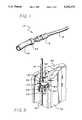
- FIG. 1is a perspective view of a flow control valve in accordance with the present invention, connected between first and second conduits;
- FIG. 2is an enlarged cross-sectional view of the interior of the valve body and plunger component
- FIG. 3is a perspective view illustrating the valve as accommodated in an automated actuation mechanism installed in an infusion device
- FIG. 4is a cross-sectional view of the valve of FIG. 1 showing the valve urged into its closed position by an actuation mechanism
- FIG. 5is a cross-sectional view of the valve and actuation mechanism of FIG. 2 in which the valve has been urged into its open position by the actuation mechanism.
- FIG. 1a fluid control valve 12 according to the present invention.
- the valve 12is installed in-line between a first conduit 14 and a second conduit 16 to control the flow of fluid through the conduits.
- the valveis especially well suited for an IV administration set application.
- valve 12comprises two components, a hollow valve body 18 and a perforated plunger component 20.
- a first port 22includes a Luer-type connector formed at one end of the body 18 so as to enable interconnection with the first conduit 14. In the embodiment illustrated, this interconnection is achieved by an interference fit between the conduit's exterior surface and the interior wall of the connector.
- the interior walls of the valve body 18are cylindrical and include an elongated collar 24 having walls 26 of reduced diameter.
- a cavity 28is thus formed which is in fluid communication with the first port 22.
- a second port 30is formed at the other end of the valve body 18.
- the exterior of the valve body 18is generally cylindrical and additionally incorporates two annular shoulders 32 and 34 of rectangular cross-section.
- the plunger component 20 of the valve 12includes a port 36 formed at one end so as to facilitate interconnection to the second conduit 16.
- the conduit 16is fitted about the exterior of the plunger component's end.
- the plunger component 20has a hollow interior comprising a longitudinal bore 38 formed in its interior which is in fluid communication with the second conduit 16 connected at its port 36.
- the opposite end of the plunger component 20is closed off 40 and the walls near the closed-off end 40 are perforated with a plurality of apertures 42.
- Part of the exterior of the plunger component 20is dimensioned to be slidingly received within the valve body's collar 24 and is of sufficient length so that the apertures 42 in the wall of the plunger component 20 clear the reduced diameter collar 24 and extend into the cavity 28.
- the plunger componentalso includes a shoulder 43 to limit its movement into the valve body 18.
- a series of annular ridges 44are formed on the plunger components' 20 exterior wall to provide for a sealing engagement with the collar's 24 interior surface 26. An interference fit is established between the annular ridges 44 and the interior surface 26 of the collar 24.
- the ridgesmay be formed of a pliable material such as Hytrel®. In this embodiment, two ridges 44 are positioned above the apertures 42 and two below.
- three annular ridges or protrusions 46are formed on the surface 26 of the collar 24. These ridges 46 also provide a seal between the plunger component 20 and the collar 24 but are primarily used to indicate to the user the relative positions of the body 18 and plunger component 20.
- the ridge 44 nearest the cavity 28cooperates with the two ridges 44 of the plunger component adjacent the closed end.
- the top ridge 46 of the collarwill be located between the two top ridges 44 of the plunger. An increased force will be felt as the plunger is telescoped out of the body and an audible click will be heard as the ridges are pulled over one another.
- the other two ridges of the plunger component 20will similarly interact with the other ridges of the collar to aid in indicating the position of the components relative to each other. Similarly, as the plunger component is telescoped into the cavity 28, clicks will be heard.
- the ridgesare also numerous enough and rigid enough to prevent inadvertent and undesirable relative movement of the body 18 and plunger 20 once positioned.
- FIG. 3illustrates the valve 12 in cooperation with an actuation mechanism which has been integrated into an infusion pump housing 50 such that the valve 12 is actuated upon movement of the door 52.
- the plunger component 20is firmly held in place about its external shoulder 43 by a stationary clamp 54 mounted to the housing 50 while a second clamp in the form of a movable actuation arm 56 engages the valve body between its two annular shoulders 32 and 34.
- the actuation arm 56is hingedly attached to the pump housing 50 and is biased upwardly by a spring 58.
- a pin 60is rigidly attached to and extends from the housing door 52 and is configured and positioned to engage the arm's actuation plate 62 and urge it downwardly as the door 52 is swung closed about its hinged axis.
- the leading edge 64 of the actuation plate 62is slightly downturned to facilitate proper engagement with the pin 60.
- the upwardly biased actuation arm 56maintains the two valve components 18 and 20 in a partially pulled apart relationship until the door 52 is closed. Closing the door 52 causes the pin 60 to press the actuating arm 56 downward overcoming the bias generated by the spring 58, causing the valve body 18 to be moved towards the plunger component 20. This is shown in greater detail in FIGS. 4 and 5.
- conduits 14 and 16are simply slipped onto or into the valve's 12 respective ends.
- the flow of fluid supplied by conduit 14is blocked as the retracted closed end 40 of the plunger component 20 creates a dead end within the collar 24 of the valve body 18.
- the engagement of the collar's interior wall by the annular ridges 44ensures that no fluid escapes from the cavity 28 of the valve body into the plunger component 20.
- FIGS. 4 and 5The operation of the actuation mechanism shown in FIG. 3 is also shown in FIGS. 4 and 5.
- the pin 60 of the dooris not in engagement with the actuation plate 62, thus the bias spring 58 (FIG. 3) causes the hinged arm 62 to pull the body 18 away from the plunger component 20 into the flow stop position.
- the rigidity and number of the ridges, both on the plunger component and on the collarprevent the plunger component from being fully pulled out of the valve body. Also, the travel distance of the actuating plate 62 is limited.
- the pin 60has engaged the actuating plate 62 and forced it downward overcoming the biasing force of the spring 58 (FIG. 3). This action has telescoped the body 18 and plunger component 20 together until the stop surface 43 of the plunger component encounters the second port 30 of the body 18. In this position, the apertures 42 are positioned in the cavity of the valve body and fluid is permitted to flow through the valve 12.
- valve's two components 18 and 20are preferably injection molded wherein the valve body is preferably formed of PVC or ABS while the plunger component is formed of Hytrel.
- the inherent resiliency of Hytrelallows the annular ridges 36 to form a tight seal against the collar 24.
Landscapes
- Health & Medical Sciences (AREA)
- Engineering & Computer Science (AREA)
- Heart & Thoracic Surgery (AREA)
- Anesthesiology (AREA)
- Pulmonology (AREA)
- General Engineering & Computer Science (AREA)
- Biomedical Technology (AREA)
- Hematology (AREA)
- Life Sciences & Earth Sciences (AREA)
- Animal Behavior & Ethology (AREA)
- General Health & Medical Sciences (AREA)
- Public Health (AREA)
- Veterinary Medicine (AREA)
- Mechanical Engineering (AREA)
- Infusion, Injection, And Reservoir Apparatuses (AREA)
Abstract
Description
Claims (26)
Priority Applications (3)
| Application Number | Priority Date | Filing Date | Title |
|---|---|---|---|
| US07/881,745US5336174A (en) | 1992-05-07 | 1992-05-07 | Flow control valve |
| DE69308366TDE69308366T2 (en) | 1992-05-07 | 1993-05-07 | Flow valve |
| EP93107469AEP0569030B1 (en) | 1992-05-07 | 1993-05-07 | Flow control valve |
Applications Claiming Priority (1)
| Application Number | Priority Date | Filing Date | Title |
|---|---|---|---|
| US07/881,745US5336174A (en) | 1992-05-07 | 1992-05-07 | Flow control valve |
Publications (1)
| Publication Number | Publication Date |
|---|---|
| US5336174Atrue US5336174A (en) | 1994-08-09 |
Family
ID=25379117
Family Applications (1)
| Application Number | Title | Priority Date | Filing Date |
|---|---|---|---|
| US07/881,745Expired - LifetimeUS5336174A (en) | 1992-05-07 | 1992-05-07 | Flow control valve |
Country Status (3)
| Country | Link |
|---|---|
| US (1) | US5336174A (en) |
| EP (1) | EP0569030B1 (en) |
| DE (1) | DE69308366T2 (en) |
Cited By (53)
| Publication number | Priority date | Publication date | Assignee | Title |
|---|---|---|---|---|
| US5540668A (en)* | 1995-01-20 | 1996-07-30 | Wilson, Jr.; Roland B. | Anti-cross contamination valve and fluid delivery systems using same |
| US5772637A (en)* | 1995-06-07 | 1998-06-30 | Deka Products Limited Partnership | Intravenous-line flow-control system |
| US5788215A (en)* | 1995-12-29 | 1998-08-04 | Rymed Technologies | Medical intravenous administration line connectors having a luer or pressure activated valve |
| US5833213A (en)* | 1995-12-29 | 1998-11-10 | Rymed Technologies, Inc. | Multiple dose drug vial adapter for use with a vial having a pierceable septum and a needleless syringe |
| US5954485A (en)* | 1996-08-14 | 1999-09-21 | Sims Deltec, Inc. | Free-flow protection devices and methods |
| US5954313A (en)* | 1995-12-29 | 1999-09-21 | Rymed Technologies, Inc. | Medical intravenous administration line connectors having a luer activated valve |
| US5993416A (en)* | 1998-01-15 | 1999-11-30 | Medtronic Ave, Inc. | Method and apparatus for regulating the fluid flow rate to and preventing over-pressurization of a balloon catheter |
| US6050973A (en)* | 1998-09-14 | 2000-04-18 | Ave Connaught | Pressure limiting device |
| US6090083A (en)* | 1996-01-31 | 2000-07-18 | Scimed Life Systems, Inc. | Low profile valve and balloon catheter |
| US6325778B1 (en) | 1996-05-20 | 2001-12-04 | Medtronic Percusurge, Inc. | Low profile catheter valve and inflation adaptor |
| US20020007156A1 (en)* | 2000-05-11 | 2002-01-17 | Miles Scott D. | Apparatus and method for preventing free flow in an infusion line |
| US6355014B1 (en) | 1996-05-20 | 2002-03-12 | Medtronic Percusurge, Inc. | Low profile catheter valve |
| US6475185B1 (en) | 2000-02-24 | 2002-11-05 | Scimed Life Systems, Inc. | Occlusion device |
| US6786888B1 (en) | 1996-05-20 | 2004-09-07 | Medtronic Ave, Inc. | Low profile catheter for emboli protection |
| US20040195538A1 (en)* | 2003-04-03 | 2004-10-07 | Raines Kenneth C | Injection port valve |
| US20040220542A1 (en)* | 2000-05-11 | 2004-11-04 | David Cise | Apparatus and method for preventing free flow in an infusion line |
| US20050015075A1 (en)* | 2003-07-14 | 2005-01-20 | B & D Research And Development Inc. | Coupling device for medical lines |
| US20050137622A1 (en)* | 2003-12-23 | 2005-06-23 | Scimed Life Systems, Inc. | Catheter with distal occlusion |
| US20060050120A1 (en)* | 2004-09-08 | 2006-03-09 | Christian Jackson | IR transparent inkjet ink set |
| US20060050119A1 (en)* | 2004-09-08 | 2006-03-09 | Christian Jackson | IR transparent cyan inkjet ink |
| US20060058740A1 (en)* | 2000-05-11 | 2006-03-16 | David Cise | Apparatus and method for preventing free flow in an infusion line |
| USD536783S1 (en) | 2002-06-28 | 2007-02-13 | Zevex, Inc. | Enteral feeding pump cassette connector |
| US20070078431A1 (en)* | 2005-09-30 | 2007-04-05 | Sherwood Services Ag | Administration feeding set and flow control apparatus with secure loading features |
| US20070208306A1 (en)* | 2006-03-02 | 2007-09-06 | Sherwood Services Ag | Pumping apparatus with secure loading features |
| US20070232859A1 (en)* | 2006-02-24 | 2007-10-04 | U.S. Endoscopy Group, Inc. | Endoscopic suction device |
| US20070253833A1 (en)* | 2006-03-02 | 2007-11-01 | Tyco Healthcare Group Lp | Pump Set with Safety Interlock |
| US20070260195A1 (en)* | 2006-05-04 | 2007-11-08 | Joel Bartholomew | Needleless access port valves |
| US20070270756A1 (en)* | 2006-05-22 | 2007-11-22 | Peter Peppel | Needleless access port valves |
| US20080147008A1 (en)* | 2006-12-15 | 2008-06-19 | Tyco Healthcare Group Lp | Optical detection of medical pump rotor position |
| US20080167617A1 (en)* | 2007-01-05 | 2008-07-10 | Tyco Heathcare Group Lp | Pump set for administering fluid with secure loading features and manufacture of component therefor |
| US20090254034A1 (en)* | 2008-04-01 | 2009-10-08 | Kent Beck | Safety occluder and method of use |
| US20100082001A1 (en)* | 2008-04-01 | 2010-04-01 | Kent Beck | Anti-free flow mechanism for enteral feeding pumps |
| US7713249B2 (en) | 1991-12-18 | 2010-05-11 | Icu Medical, Inc. | Medical valve and method of use |
| US7758551B2 (en) | 2006-03-02 | 2010-07-20 | Covidien Ag | Pump set with secure loading features |
| US7763005B2 (en) | 2006-03-02 | 2010-07-27 | Covidien Ag | Method for using a pump set having secure loading features |
| US20110021979A1 (en)* | 2006-03-02 | 2011-01-27 | Hudson Joseph A | Enteral Feeding Set and Interlock Device Therefor |
| US20110048423A1 (en)* | 2009-08-31 | 2011-03-03 | Leffel William A | Valve system for use with a flexible gas supply tube extending to a patient |
| USD634005S1 (en) | 2002-09-09 | 2011-03-08 | Zevex, Inc. | In-line occluder |
| USD635664S1 (en) | 2002-09-09 | 2011-04-05 | Zevex, Inc. | In-line occluder |
| US7998121B2 (en) | 2009-02-06 | 2011-08-16 | Zevex, Inc. | Automatic safety occluder |
| US8002765B2 (en) | 1995-12-15 | 2011-08-23 | Icu Medical, Inc. | Medical valve with fluid escape space |
| US8053721B2 (en) | 2006-12-11 | 2011-11-08 | Tyco Healthcare Group Lp | Pump set and pump with electromagnetic radiation operated interlock |
| US8154274B2 (en) | 2010-05-11 | 2012-04-10 | Tyco Healthcare Group Lp | Safety interlock |
| US8287495B2 (en) | 2009-07-30 | 2012-10-16 | Tandem Diabetes Care, Inc. | Infusion pump system with disposable cartridge having pressure venting and pressure feedback |
| USD672455S1 (en) | 2010-10-01 | 2012-12-11 | Zevex, Inc. | Fluid delivery cassette |
| US8425470B2 (en) | 2008-04-01 | 2013-04-23 | Zevex, Inc. | Anti-free-flow mechanism for enteral feeding pumps |
| US8911414B2 (en) | 2010-10-01 | 2014-12-16 | Zevex, Inc. | Anti free-flow occluder and priming actuator pad |
| US8974415B2 (en) | 2012-04-10 | 2015-03-10 | Smiths Medical Asd, Inc. | Flow stop insert apparatus and methods |
| US9662437B2 (en) | 2014-04-28 | 2017-05-30 | Smiths Medical Asd, Inc. | Infusion pump pressure plate |
| US9962486B2 (en) | 2013-03-14 | 2018-05-08 | Tandem Diabetes Care, Inc. | System and method for detecting occlusions in an infusion pump |
| US10071621B2 (en) | 2015-09-03 | 2018-09-11 | Mgi Coutier Espana Sl | Automotive equipment for equipping an automotive set and an automotive set comprising such an automotive equipment |
| US10258736B2 (en) | 2012-05-17 | 2019-04-16 | Tandem Diabetes Care, Inc. | Systems including vial adapter for fluid transfer |
| CN113530940A (en)* | 2020-04-13 | 2021-10-22 | 普尔曼公司 | Bush with split bolt |
Families Citing this family (14)
| Publication number | Priority date | Publication date | Assignee | Title |
|---|---|---|---|---|
| GB9413193D0 (en)* | 1994-06-30 | 1994-08-24 | Graseby Medical Ltd | Anti-freeflow devices for medical apparatus |
| US5814024A (en)* | 1996-11-27 | 1998-09-29 | Elcam Plastics | Needleless valve |
| US5807348A (en)* | 1996-11-27 | 1998-09-15 | Elcam Plastics | Needleless valve |
| US6261262B1 (en)* | 1997-06-12 | 2001-07-17 | Abbott Laboratories | Pump with anti-free flow feature |
| US6056522A (en)* | 1998-05-13 | 2000-05-02 | Sims Deltec, Inc. | Reusable cassette with a moveable door |
| GB2343723A (en)* | 1998-10-14 | 2000-05-17 | Margaret Pamela Richardson | Medical fluid line arrangement |
| DE10011724C1 (en)* | 2000-03-10 | 2001-04-26 | Fresenius Medical Care De Gmbh | Connector for sterile packed fluid systems, such as kidney dialysis fluid flow system, comprises connections at both ends, each having inner slides with limit stops |
| FR2824127B1 (en)* | 2001-04-26 | 2003-06-27 | Snecma Moteurs | LUBRICATION INTERRUPTION DEVICE |
| WO2013010580A1 (en)* | 2011-07-18 | 2013-01-24 | Cedic S.R.L. | Anti free flow valve |
| US20150133861A1 (en) | 2013-11-11 | 2015-05-14 | Kevin P. McLennan | Thermal management system and method for medical devices |
| US10143795B2 (en) | 2014-08-18 | 2018-12-04 | Icu Medical, Inc. | Intravenous pole integrated power, control, and communication system and method for an infusion pump |
| NZ737340A (en) | 2015-05-26 | 2019-06-28 | Icu Medical Inc | Disposable infusion fluid delivery device for programmable large volume drug delivery |
| USD939079S1 (en) | 2019-08-22 | 2021-12-21 | Icu Medical, Inc. | Infusion pump |
| USD1052728S1 (en) | 2021-11-12 | 2024-11-26 | Icu Medical, Inc. | Medical fluid infusion pump |
Citations (15)
| Publication number | Priority date | Publication date | Assignee | Title |
|---|---|---|---|---|
| US2088656A (en)* | 1936-04-20 | 1937-08-03 | George C Lamb | Pneumatic tire valve |
| US2995144A (en)* | 1958-08-18 | 1961-08-08 | Manning Oscar | Snap action float valve |
| US3570484A (en)* | 1967-08-31 | 1971-03-16 | Eschmann Bros & Walsh Ltd | Intravenous valve assembly |
| US3806086A (en)* | 1973-03-15 | 1974-04-23 | Nosco Plastics | Automatic shut-off valve for administration of sterile fluids |
| US3971541A (en)* | 1975-01-03 | 1976-07-27 | Griffin Raymond E | Manually operable self-closing valve |
| DE2936496A1 (en)* | 1978-09-13 | 1980-03-27 | Gambro Dialysatoren | DEVICE FOR CONNECTING HOSES OR THE LIKE |
| DE3003398A1 (en)* | 1979-02-02 | 1980-08-07 | Sperry Corp | Computer-controlled connecting union for fluids - consists of easily connectable and releasable modules providing double sealing |
| DE3202422A1 (en)* | 1982-01-26 | 1983-07-28 | Bell-Hermetic-Armaturenwerk GmbH & Co KG, 3509 Spangenberg | Coupling |
| EP0028601B1 (en)* | 1979-01-22 | 1983-08-31 | SVENSSON, Jan Axel | Slide valve and coupler assembly |
| US4430073A (en)* | 1982-05-03 | 1984-02-07 | Bemis Manufacturing Company | Surgical suction probe with reversible valve |
| US4689043A (en)* | 1986-03-19 | 1987-08-25 | Imed Corporation | IV tube activator |
| US4856756A (en)* | 1988-10-31 | 1989-08-15 | Combs Linsey L | Well bottom release valve |
| US4904236A (en)* | 1987-01-30 | 1990-02-27 | Vir Engineering | Fluid flow control valve |
| US5116021A (en)* | 1986-03-04 | 1992-05-26 | Deka Products Limited Partnership | Quick-disconnect valve |
| US5148830A (en)* | 1991-08-30 | 1992-09-22 | Hung Liu | Flow control device |
- 1992
- 1992-05-07USUS07/881,745patent/US5336174A/ennot_activeExpired - Lifetime
- 1993
- 1993-05-07DEDE69308366Tpatent/DE69308366T2/ennot_activeExpired - Fee Related
- 1993-05-07EPEP93107469Apatent/EP0569030B1/ennot_activeExpired - Lifetime
Patent Citations (16)
| Publication number | Priority date | Publication date | Assignee | Title |
|---|---|---|---|---|
| US2088656A (en)* | 1936-04-20 | 1937-08-03 | George C Lamb | Pneumatic tire valve |
| US2995144A (en)* | 1958-08-18 | 1961-08-08 | Manning Oscar | Snap action float valve |
| US3570484A (en)* | 1967-08-31 | 1971-03-16 | Eschmann Bros & Walsh Ltd | Intravenous valve assembly |
| US3806086A (en)* | 1973-03-15 | 1974-04-23 | Nosco Plastics | Automatic shut-off valve for administration of sterile fluids |
| US3971541A (en)* | 1975-01-03 | 1976-07-27 | Griffin Raymond E | Manually operable self-closing valve |
| DE2936496A1 (en)* | 1978-09-13 | 1980-03-27 | Gambro Dialysatoren | DEVICE FOR CONNECTING HOSES OR THE LIKE |
| US4265428A (en)* | 1978-09-13 | 1981-05-05 | Gambro Dialysatoren Gmbh & Co. Kg | Connection device for providing selective fluid communication between first and second conduits |
| EP0028601B1 (en)* | 1979-01-22 | 1983-08-31 | SVENSSON, Jan Axel | Slide valve and coupler assembly |
| DE3003398A1 (en)* | 1979-02-02 | 1980-08-07 | Sperry Corp | Computer-controlled connecting union for fluids - consists of easily connectable and releasable modules providing double sealing |
| DE3202422A1 (en)* | 1982-01-26 | 1983-07-28 | Bell-Hermetic-Armaturenwerk GmbH & Co KG, 3509 Spangenberg | Coupling |
| US4430073A (en)* | 1982-05-03 | 1984-02-07 | Bemis Manufacturing Company | Surgical suction probe with reversible valve |
| US5116021A (en)* | 1986-03-04 | 1992-05-26 | Deka Products Limited Partnership | Quick-disconnect valve |
| US4689043A (en)* | 1986-03-19 | 1987-08-25 | Imed Corporation | IV tube activator |
| US4904236A (en)* | 1987-01-30 | 1990-02-27 | Vir Engineering | Fluid flow control valve |
| US4856756A (en)* | 1988-10-31 | 1989-08-15 | Combs Linsey L | Well bottom release valve |
| US5148830A (en)* | 1991-08-30 | 1992-09-22 | Hung Liu | Flow control device |
Cited By (112)
| Publication number | Priority date | Publication date | Assignee | Title |
|---|---|---|---|---|
| US7717886B2 (en) | 1991-12-18 | 2010-05-18 | Icu Medical, Inc. | Medical valve and method of use |
| US7713249B2 (en) | 1991-12-18 | 2010-05-11 | Icu Medical, Inc. | Medical valve and method of use |
| US7713248B2 (en) | 1991-12-18 | 2010-05-11 | Icu Medical, Inc. | Medical valve and method of use |
| US7717883B2 (en) | 1991-12-18 | 2010-05-18 | Icu Medical, Inc. | Medical valve and method of use |
| US7722576B2 (en) | 1991-12-18 | 2010-05-25 | Icu Medical, Inc. | Medical valve and method of use |
| US7717887B2 (en) | 1991-12-18 | 2010-05-18 | Icu Medical, Inc. | Medical valve and method of use |
| US7713247B2 (en) | 1991-12-18 | 2010-05-11 | Icu Medical, Inc. | Medical valve and method of use |
| US7717885B2 (en) | 1991-12-18 | 2010-05-18 | Icu Medical, Inc. | Medical valve and method of use |
| US7717884B2 (en) | 1991-12-18 | 2010-05-18 | Icu Medical, Inc. | Medical valve and method of use |
| US7722575B2 (en) | 1991-12-18 | 2010-05-25 | Icu Medical, Inc. | Medical valve and method of use |
| US5540668A (en)* | 1995-01-20 | 1996-07-30 | Wilson, Jr.; Roland B. | Anti-cross contamination valve and fluid delivery systems using same |
| US5916201A (en)* | 1995-01-20 | 1999-06-29 | Wilson, Jr.; Roland B. | Anti-cross contamination valve and fluid delivery systems using same |
| US5772637A (en)* | 1995-06-07 | 1998-06-30 | Deka Products Limited Partnership | Intravenous-line flow-control system |
| US8002765B2 (en) | 1995-12-15 | 2011-08-23 | Icu Medical, Inc. | Medical valve with fluid escape space |
| US6158458A (en)* | 1995-12-29 | 2000-12-12 | Ryan; Dana Wm. | Medical intravenous administration line connectors having a luer or pressure activated valve |
| US5954313A (en)* | 1995-12-29 | 1999-09-21 | Rymed Technologies, Inc. | Medical intravenous administration line connectors having a luer activated valve |
| US5833213A (en)* | 1995-12-29 | 1998-11-10 | Rymed Technologies, Inc. | Multiple dose drug vial adapter for use with a vial having a pierceable septum and a needleless syringe |
| US5788215A (en)* | 1995-12-29 | 1998-08-04 | Rymed Technologies | Medical intravenous administration line connectors having a luer or pressure activated valve |
| US6926729B1 (en) | 1996-01-31 | 2005-08-09 | Scimed Life Systems, Inc. | Low profile valve and method of making |
| US6090083A (en)* | 1996-01-31 | 2000-07-18 | Scimed Life Systems, Inc. | Low profile valve and balloon catheter |
| US6355014B1 (en) | 1996-05-20 | 2002-03-12 | Medtronic Percusurge, Inc. | Low profile catheter valve |
| US6786888B1 (en) | 1996-05-20 | 2004-09-07 | Medtronic Ave, Inc. | Low profile catheter for emboli protection |
| US6325778B1 (en) | 1996-05-20 | 2001-12-04 | Medtronic Percusurge, Inc. | Low profile catheter valve and inflation adaptor |
| US5954485A (en)* | 1996-08-14 | 1999-09-21 | Sims Deltec, Inc. | Free-flow protection devices and methods |
| US6110144A (en)* | 1998-01-15 | 2000-08-29 | Medtronic Ave, Inc. | Method and apparatus for regulating the fluid flow rate to and preventing over-pressurization of a balloon catheter |
| US5993416A (en)* | 1998-01-15 | 1999-11-30 | Medtronic Ave, Inc. | Method and apparatus for regulating the fluid flow rate to and preventing over-pressurization of a balloon catheter |
| US6050973A (en)* | 1998-09-14 | 2000-04-18 | Ave Connaught | Pressure limiting device |
| US6689098B2 (en) | 2000-02-24 | 2004-02-10 | Scimed Life Systems, Inc. | Occlusion device |
| US6475185B1 (en) | 2000-02-24 | 2002-11-05 | Scimed Life Systems, Inc. | Occlusion device |
| US20040220542A1 (en)* | 2000-05-11 | 2004-11-04 | David Cise | Apparatus and method for preventing free flow in an infusion line |
| US20060058740A1 (en)* | 2000-05-11 | 2006-03-16 | David Cise | Apparatus and method for preventing free flow in an infusion line |
| US7150727B2 (en) | 2000-05-11 | 2006-12-19 | Zevex, Inc. | Apparatus and method for preventing free flow in an infusion line |
| US6979311B2 (en) | 2000-05-11 | 2005-12-27 | Zevex, Inc. | Apparatus and method for preventing free flow in an infusion line |
| US7976513B2 (en) | 2000-05-11 | 2011-07-12 | Zevex, Inc. | Apparatus and method for selectively controlling flow in an infusion line |
| US20050283121A1 (en)* | 2000-05-11 | 2005-12-22 | David Cise | Apparatus and method for preventing free flow in an infusion line |
| US20050119625A1 (en)* | 2000-05-11 | 2005-06-02 | Scott Miles | Apparatus and method for preventing free flow in an infusion line |
| US7815612B2 (en) | 2000-05-11 | 2010-10-19 | Zevex, Inc. | Apparatus and method for preventing free flow in an infusion line |
| US6623447B2 (en)* | 2000-05-11 | 2003-09-23 | Zevex, Inc. | Apparatus and method for preventing free flow in an infusion line |
| US20020007156A1 (en)* | 2000-05-11 | 2002-01-17 | Miles Scott D. | Apparatus and method for preventing free flow in an infusion line |
| US7367963B2 (en)* | 2000-05-11 | 2008-05-06 | Zevex, Inc. | Apparatus and method for preventing free flow in an infusion line |
| USD536783S1 (en) | 2002-06-28 | 2007-02-13 | Zevex, Inc. | Enteral feeding pump cassette connector |
| USD634005S1 (en) | 2002-09-09 | 2011-03-08 | Zevex, Inc. | In-line occluder |
| USD635664S1 (en) | 2002-09-09 | 2011-04-05 | Zevex, Inc. | In-line occluder |
| US6871838B2 (en) | 2003-04-03 | 2005-03-29 | B. Braun Medical Inc. | Injection port valve |
| US20040195538A1 (en)* | 2003-04-03 | 2004-10-07 | Raines Kenneth C | Injection port valve |
| US20050015075A1 (en)* | 2003-07-14 | 2005-01-20 | B & D Research And Development Inc. | Coupling device for medical lines |
| US9232948B2 (en) | 2003-12-23 | 2016-01-12 | Stryker Corporation | Catheter with distal occlusion apparatus |
| US20050137622A1 (en)* | 2003-12-23 | 2005-06-23 | Scimed Life Systems, Inc. | Catheter with distal occlusion |
| US20060050120A1 (en)* | 2004-09-08 | 2006-03-09 | Christian Jackson | IR transparent inkjet ink set |
| US7351277B2 (en) | 2004-09-08 | 2008-04-01 | E. I. Du Pont De Nemours And Company | IR transparent cyan inkjet ink |
| US7407538B2 (en) | 2004-09-08 | 2008-08-05 | E.I. Du Pont De Nemours And Company | IR transparent inkjet ink set |
| US20060050119A1 (en)* | 2004-09-08 | 2006-03-09 | Christian Jackson | IR transparent cyan inkjet ink |
| US20070078431A1 (en)* | 2005-09-30 | 2007-04-05 | Sherwood Services Ag | Administration feeding set and flow control apparatus with secure loading features |
| US7846131B2 (en)* | 2005-09-30 | 2010-12-07 | Covidien Ag | Administration feeding set and flow control apparatus with secure loading features |
| US8251945B2 (en)* | 2006-02-24 | 2012-08-28 | U.S. Endoscopy Group, Inc. | Endoscopic suction device |
| US20070232859A1 (en)* | 2006-02-24 | 2007-10-04 | U.S. Endoscopy Group, Inc. | Endoscopic suction device |
| US8142404B2 (en) | 2006-03-02 | 2012-03-27 | Covidien Ag | Controller for pumping apparatus |
| US8052643B2 (en) | 2006-03-02 | 2011-11-08 | Tyco Healthcare Group Lp | Enteral feeding set and interlock device therefor |
| US7722562B2 (en) | 2006-03-02 | 2010-05-25 | Tyco Healthcare Group Lp | Pump set with safety interlock |
| US7758551B2 (en) | 2006-03-02 | 2010-07-20 | Covidien Ag | Pump set with secure loading features |
| US7763005B2 (en) | 2006-03-02 | 2010-07-27 | Covidien Ag | Method for using a pump set having secure loading features |
| US20100198145A1 (en)* | 2006-03-02 | 2010-08-05 | Tyco Healthcare Group Lp | Pump set with safety interlock |
| US8142399B2 (en) | 2006-03-02 | 2012-03-27 | Tyco Healthcare Group Lp | Pump set with safety interlock |
| US20100198144A1 (en)* | 2006-03-02 | 2010-08-05 | Covidien Ag | Method for using a pump set having secure loading features |
| US9402789B2 (en) | 2006-03-02 | 2016-08-02 | Covidien Ag | Pump set having secure loading features |
| US20070208306A1 (en)* | 2006-03-02 | 2007-09-06 | Sherwood Services Ag | Pumping apparatus with secure loading features |
| US20110021979A1 (en)* | 2006-03-02 | 2011-01-27 | Hudson Joseph A | Enteral Feeding Set and Interlock Device Therefor |
| US8052642B2 (en) | 2006-03-02 | 2011-11-08 | Covidien Ag | Pumping apparatus with secure loading features |
| US20100056994A1 (en)* | 2006-03-02 | 2010-03-04 | Covidien Ag | Pumping apparatus with secure loading features |
| US20070253833A1 (en)* | 2006-03-02 | 2007-11-01 | Tyco Healthcare Group Lp | Pump Set with Safety Interlock |
| US7722573B2 (en) | 2006-03-02 | 2010-05-25 | Covidien Ag | Pumping apparatus with secure loading features |
| US7927304B2 (en) | 2006-03-02 | 2011-04-19 | Tyco Healthcare Group Lp | Enteral feeding pump and feeding set therefor |
| US20070260195A1 (en)* | 2006-05-04 | 2007-11-08 | Joel Bartholomew | Needleless access port valves |
| US7867204B2 (en) | 2006-05-04 | 2011-01-11 | B. Braun Medical Inc. | Needleless access port valves |
| US20070270756A1 (en)* | 2006-05-22 | 2007-11-22 | Peter Peppel | Needleless access port valves |
| US8053721B2 (en) | 2006-12-11 | 2011-11-08 | Tyco Healthcare Group Lp | Pump set and pump with electromagnetic radiation operated interlock |
| US20080147008A1 (en)* | 2006-12-15 | 2008-06-19 | Tyco Healthcare Group Lp | Optical detection of medical pump rotor position |
| US20080167617A1 (en)* | 2007-01-05 | 2008-07-10 | Tyco Heathcare Group Lp | Pump set for administering fluid with secure loading features and manufacture of component therefor |
| US8021336B2 (en) | 2007-01-05 | 2011-09-20 | Tyco Healthcare Group Lp | Pump set for administering fluid with secure loading features and manufacture of component therefor |
| US8529511B2 (en) | 2007-01-05 | 2013-09-10 | Covidien Lp | Pump set with secure loading features and related methods therefor |
| US20090254034A1 (en)* | 2008-04-01 | 2009-10-08 | Kent Beck | Safety occluder and method of use |
| US9017296B2 (en) | 2008-04-01 | 2015-04-28 | Zevex, Inc. | Safety occluder and method of use |
| US20100082001A1 (en)* | 2008-04-01 | 2010-04-01 | Kent Beck | Anti-free flow mechanism for enteral feeding pumps |
| US8876787B2 (en) | 2008-04-01 | 2014-11-04 | Zevex, Inc. | Anti-free-flow mechanism for enteral feeding pumps |
| US20110028899A1 (en)* | 2008-04-01 | 2011-02-03 | Kent Beck | Anti-free flow mechanism for enteral feeding pumps |
| US8425470B2 (en) | 2008-04-01 | 2013-04-23 | Zevex, Inc. | Anti-free-flow mechanism for enteral feeding pumps |
| US8343111B2 (en) | 2008-04-01 | 2013-01-01 | Zevex, Inc. | Anti-free flow mechanism for enteral feeding pumps |
| US8491543B2 (en) | 2009-02-06 | 2013-07-23 | Zevex, Inc. | Automatic safety occluder |
| US7998121B2 (en) | 2009-02-06 | 2011-08-16 | Zevex, Inc. | Automatic safety occluder |
| US9211377B2 (en) | 2009-07-30 | 2015-12-15 | Tandem Diabetes Care, Inc. | Infusion pump system with disposable cartridge having pressure venting and pressure feedback |
| US8298184B2 (en) | 2009-07-30 | 2012-10-30 | Tandem Diabetes Care, Inc. | Infusion pump system with disposable cartridge having pressure venting and pressure feedback |
| US11285263B2 (en) | 2009-07-30 | 2022-03-29 | Tandem Diabetes Care, Inc. | Infusion pump systems and methods |
| US8758323B2 (en) | 2009-07-30 | 2014-06-24 | Tandem Diabetes Care, Inc. | Infusion pump system with disposable cartridge having pressure venting and pressure feedback |
| US8287495B2 (en) | 2009-07-30 | 2012-10-16 | Tandem Diabetes Care, Inc. | Infusion pump system with disposable cartridge having pressure venting and pressure feedback |
| US12042627B2 (en) | 2009-07-30 | 2024-07-23 | Tandem Diabetes Care, Inc. | Infusion pump systems and methods |
| US8926561B2 (en) | 2009-07-30 | 2015-01-06 | Tandem Diabetes Care, Inc. | Infusion pump system with disposable cartridge having pressure venting and pressure feedback |
| US12144964B2 (en) | 2009-07-30 | 2024-11-19 | Tandem Diabetes Care, Inc | Infusion pump system with disposable cartridge having pressure venting and pressure feedback |
| US11135362B2 (en) | 2009-07-30 | 2021-10-05 | Tandem Diabetes Care, Inc. | Infusion pump systems and methods |
| US20110048423A1 (en)* | 2009-08-31 | 2011-03-03 | Leffel William A | Valve system for use with a flexible gas supply tube extending to a patient |
| US9067038B2 (en)* | 2009-08-31 | 2015-06-30 | William A. Leffel | Valve system for use with a flexible gas supply tube extending to a patient |
| US8154274B2 (en) | 2010-05-11 | 2012-04-10 | Tyco Healthcare Group Lp | Safety interlock |
| US8760146B2 (en) | 2010-05-11 | 2014-06-24 | Covidien Lp | Safety interlock |
| USD672455S1 (en) | 2010-10-01 | 2012-12-11 | Zevex, Inc. | Fluid delivery cassette |
| US8911414B2 (en) | 2010-10-01 | 2014-12-16 | Zevex, Inc. | Anti free-flow occluder and priming actuator pad |
| US8974415B2 (en) | 2012-04-10 | 2015-03-10 | Smiths Medical Asd, Inc. | Flow stop insert apparatus and methods |
| US9789251B2 (en) | 2012-04-10 | 2017-10-17 | Smiths Medical Asd, Inc. | Flow stop insert apparatus and methods |
| US10258736B2 (en) | 2012-05-17 | 2019-04-16 | Tandem Diabetes Care, Inc. | Systems including vial adapter for fluid transfer |
| US9962486B2 (en) | 2013-03-14 | 2018-05-08 | Tandem Diabetes Care, Inc. | System and method for detecting occlusions in an infusion pump |
| US9662437B2 (en) | 2014-04-28 | 2017-05-30 | Smiths Medical Asd, Inc. | Infusion pump pressure plate |
| US10071621B2 (en) | 2015-09-03 | 2018-09-11 | Mgi Coutier Espana Sl | Automotive equipment for equipping an automotive set and an automotive set comprising such an automotive equipment |
| CN113530940A (en)* | 2020-04-13 | 2021-10-22 | 普尔曼公司 | Bush with split bolt |
| CN113530940B (en)* | 2020-04-13 | 2023-12-08 | 普尔曼公司 | Bushing with split bolt |
Also Published As
| Publication number | Publication date |
|---|---|
| DE69308366D1 (en) | 1997-04-10 |
| EP0569030B1 (en) | 1997-03-05 |
| DE69308366T2 (en) | 1997-08-14 |
| EP0569030A1 (en) | 1993-11-10 |
Similar Documents
| Publication | Publication Date | Title |
|---|---|---|
| US5336174A (en) | Flow control valve | |
| US4576199A (en) | Slide valve and coupling unit | |
| US5453098A (en) | Two step IV fluid flow stop | |
| US5826621A (en) | Valve apparatus | |
| US5289849A (en) | Control of fluid flow | |
| RU2225232C2 (en) | Medical valve having properties for creating positive flow | |
| EP0635279B1 (en) | Procedure for flushing a catheter and catheter | |
| US6079432A (en) | Control of fluid flow by oval shaped valve member containing a cam interface | |
| CA2027094C (en) | Ball valve | |
| US5190067A (en) | Directional flow control | |
| US5228646A (en) | Latching trumpet valve for medical infusions | |
| EP1414515B1 (en) | Valved male luer | |
| US5746414A (en) | Fluid access and flow control valve | |
| US4506691A (en) | Three-way valve for automatic sequencing of fluid flow | |
| US5699821A (en) | Control of fluid flow | |
| US5150880A (en) | Valve assembly with flow control | |
| US5967484A (en) | Intravenous tube occluder | |
| JP2007516785A (en) | Valve assembly | |
| IL127900A (en) | Blood sampling/injecting valve | |
| US6106503A (en) | Catheter valve | |
| CA2574057A1 (en) | Automatic clamp apparatus for iv infusion sets used in pump devices | |
| US5322263A (en) | Endoscope suction operating apparatus | |
| EP1603631A1 (en) | Valved male luer | |
| JPS60129480A (en) | Safety device, method of installing said valve and method ofcontrolling said valve | |
| EP0253803A1 (en) | Slide valve and coupler assembly. |
Legal Events
| Date | Code | Title | Description |
|---|---|---|---|
| AS | Assignment | Owner name:IVAC CORPORATION, A DE CORP., CALIFORNIA Free format text:ASSIGNMENT OF ASSIGNORS INTEREST.;ASSIGNORS:DAOUD, ADIB G.;ANDERSON, EMMETT B.;REEL/FRAME:006119/0306 Effective date:19920505 | |
| STCF | Information on status: patent grant | Free format text:PATENTED CASE | |
| AS | Assignment | Owner name:IVAC MEDICAL SYSTEMS, INC., CALIFORNIA Free format text:CHANGE OF NAME;ASSIGNOR:IVAC CORPORATION;REEL/FRAME:007986/0971 Effective date:19960125 | |
| AS | Assignment | Owner name:BANKERS TRUST COMPANY, NEW YORK Free format text:SECURITY INTEREST;ASSIGNOR:IVAC HOLDINGS, INC.;REEL/FRAME:008568/0540 Effective date:19961126 | |
| AS | Assignment | Owner name:ALARIS MEDICAL SYSTEMS, INC., CALIFORNIA Free format text:CHANGE OF NAME;ASSIGNOR:IVAC HOLDINGS, INC.;REEL/FRAME:008621/0107 Effective date:19970429 Owner name:IVAC HOLDINGS, INC., CALIFORNIA Free format text:MERGER;ASSIGNOR:IVAC MEDICAL SYSTEMS, INC.;REEL/FRAME:008621/0113 Effective date:19961126 | |
| FPAY | Fee payment | Year of fee payment:4 | |
| FPAY | Fee payment | Year of fee payment:8 | |
| REMI | Maintenance fee reminder mailed | ||
| AS | Assignment | Owner name:IISBC BANK USA, NEW YORK Free format text:SECURITY INTEREST;ASSIGNOR:ALARIS MEDICAL SYSTEMS, INC.;REEL/FRAME:013403/0338 Effective date:20011016 | |
| AS | Assignment | Owner name:ALARIS MEDICAL SYSTEMS, INC., CALIFORNIA Free format text:CHANGE OF NAME;ASSIGNOR:ALARIS MEDICAL, INC.;REEL/FRAME:014201/0592 Effective date:20030630 Owner name:ALARIS MEDICAL SYSTEMS, INC., CALIFORNIA Free format text:SECURITY AGREEMENT;ASSIGNOR:HSBC BANK USA;REEL/FRAME:014220/0171 Effective date:20030630 Owner name:ALARIS MEDICAL, INC., CALIFORNIA Free format text:MERGER;ASSIGNOR:ALARIS MEDICAL SYSTEMS, INC.;REEL/FRAME:014220/0417 Effective date:20030630 Owner name:CITICORP NORTH AMERICA, INC., NEW YORK Free format text:SECURITY AGREEMENT;ASSIGNOR:ALARIS MEDICAL SYSTEMS, INC.;REEL/FRAME:014220/0315 Effective date:20030630 | |
| AS | Assignment | Owner name:ALARIS MEDICAL SYSTEMS, INC., CALIFORNIA Free format text:RELEASE OF SECURITY AGREEMENT;ASSIGNOR:CITICORP NORTH AMERICA, INC.;REEL/FRAME:015703/0127 Effective date:20040707 | |
| AS | Assignment | Owner name:CARDINAL HEALTH 303, INC., CALIFORNIA Free format text:CHANGE OF NAME;ASSIGNOR:ALARIS MEDICAL SYSTEMS, INC.;REEL/FRAME:016976/0265 Effective date:20041013 | |
| FPAY | Fee payment | Year of fee payment:12 | |
| AS | Assignment | Owner name:CAREFUSION 303, INC.,CALIFORNIA Free format text:CHANGE OF NAME;ASSIGNOR:CARDINAL HEALTH 303, INC.;REEL/FRAME:023800/0598 Effective date:20090801 Owner name:CAREFUSION 303, INC., CALIFORNIA Free format text:CHANGE OF NAME;ASSIGNOR:CARDINAL HEALTH 303, INC.;REEL/FRAME:023800/0598 Effective date:20090801 |