US5336141A - Exercise machine for simulating perambulatory movement - Google Patents
Exercise machine for simulating perambulatory movementDownload PDFInfo
- Publication number
- US5336141A US5336141AUS07/951,672US95167292AUS5336141AUS 5336141 AUS5336141 AUS 5336141AUS 95167292 AUS95167292 AUS 95167292AUS 5336141 AUS5336141 AUS 5336141A
- Authority
- US
- United States
- Prior art keywords
- support means
- frame
- foot support
- machine
- oscillators
- Prior art date
- Legal status (The legal status is an assumption and is not a legal conclusion. Google has not performed a legal analysis and makes no representation as to the accuracy of the status listed.)
- Expired - Lifetime
Links
- 230000003534oscillatory effectEffects0.000claimsabstractdescription16
- 230000004044responseEffects0.000claimsdescription6
- 239000002131composite materialSubstances0.000claimsdescription3
- 230000027455bindingEffects0.000claimsdescription2
- 238000009739bindingMethods0.000claimsdescription2
- 230000009191jumpingEffects0.000abstractdescription6
- 230000009194climbingEffects0.000abstractdescription4
- 125000006850spacer groupChemical group0.000description10
- 238000003466weldingMethods0.000description5
- 230000000694effectsEffects0.000description4
- 239000000463materialSubstances0.000description4
- 210000003205muscleAnatomy0.000description2
- 238000004088simulationMethods0.000description2
- 229910000639Spring steelInorganic materials0.000description1
- 230000003750conditioning effectEffects0.000description1
- 238000010276constructionMethods0.000description1
- 230000001351cycling effectEffects0.000description1
- 239000011152fibreglassSubstances0.000description1
- 230000013011matingEffects0.000description1
- 230000007246mechanismEffects0.000description1
- 230000004048modificationEffects0.000description1
- 238000012986modificationMethods0.000description1
- 230000010355oscillationEffects0.000description1
- 239000004033plasticSubstances0.000description1
- 230000008707rearrangementEffects0.000description1
- 239000011435rockSubstances0.000description1
- 239000007787solidSubstances0.000description1
- 238000006467substitution reactionMethods0.000description1
- 239000000725suspensionSubstances0.000description1
Images


Classifications
- A—HUMAN NECESSITIES
- A63—SPORTS; GAMES; AMUSEMENTS
- A63B—APPARATUS FOR PHYSICAL TRAINING, GYMNASTICS, SWIMMING, CLIMBING, OR FENCING; BALL GAMES; TRAINING EQUIPMENT
- A63B22/00—Exercising apparatus specially adapted for conditioning the cardio-vascular system, for training agility or co-ordination of movements
- A63B22/06—Exercising apparatus specially adapted for conditioning the cardio-vascular system, for training agility or co-ordination of movements with support elements performing a rotating cycling movement, i.e. a closed path movement
- A63B22/0664—Exercising apparatus specially adapted for conditioning the cardio-vascular system, for training agility or co-ordination of movements with support elements performing a rotating cycling movement, i.e. a closed path movement performing an elliptic movement
- A—HUMAN NECESSITIES
- A63—SPORTS; GAMES; AMUSEMENTS
- A63B—APPARATUS FOR PHYSICAL TRAINING, GYMNASTICS, SWIMMING, CLIMBING, OR FENCING; BALL GAMES; TRAINING EQUIPMENT
- A63B22/00—Exercising apparatus specially adapted for conditioning the cardio-vascular system, for training agility or co-ordination of movements
- A63B22/0002—Exercising apparatus specially adapted for conditioning the cardio-vascular system, for training agility or co-ordination of movements involving an exercising of arms
- A63B22/001—Exercising apparatus specially adapted for conditioning the cardio-vascular system, for training agility or co-ordination of movements involving an exercising of arms by simultaneously exercising arms and legs, e.g. diagonally in anti-phase
- A—HUMAN NECESSITIES
- A63—SPORTS; GAMES; AMUSEMENTS
- A63B—APPARATUS FOR PHYSICAL TRAINING, GYMNASTICS, SWIMMING, CLIMBING, OR FENCING; BALL GAMES; TRAINING EQUIPMENT
- A63B22/00—Exercising apparatus specially adapted for conditioning the cardio-vascular system, for training agility or co-ordination of movements
- A63B22/0015—Exercising apparatus specially adapted for conditioning the cardio-vascular system, for training agility or co-ordination of movements with an adjustable movement path of the support elements
- A63B22/0017—Exercising apparatus specially adapted for conditioning the cardio-vascular system, for training agility or co-ordination of movements with an adjustable movement path of the support elements the adjustment being controlled by movement of the user
- A—HUMAN NECESSITIES
- A63—SPORTS; GAMES; AMUSEMENTS
- A63B—APPARATUS FOR PHYSICAL TRAINING, GYMNASTICS, SWIMMING, CLIMBING, OR FENCING; BALL GAMES; TRAINING EQUIPMENT
- A63B22/00—Exercising apparatus specially adapted for conditioning the cardio-vascular system, for training agility or co-ordination of movements
- A63B22/06—Exercising apparatus specially adapted for conditioning the cardio-vascular system, for training agility or co-ordination of movements with support elements performing a rotating cycling movement, i.e. a closed path movement
- A63B22/0664—Exercising apparatus specially adapted for conditioning the cardio-vascular system, for training agility or co-ordination of movements with support elements performing a rotating cycling movement, i.e. a closed path movement performing an elliptic movement
- A63B2022/067—Exercising apparatus specially adapted for conditioning the cardio-vascular system, for training agility or co-ordination of movements with support elements performing a rotating cycling movement, i.e. a closed path movement performing an elliptic movement with crank and handles being on opposite sides of the exercising apparatus with respect to the frontal body-plane of the user, e.g. the crank is behind and handles are in front of the user
- A—HUMAN NECESSITIES
- A63—SPORTS; GAMES; AMUSEMENTS
- A63B—APPARATUS FOR PHYSICAL TRAINING, GYMNASTICS, SWIMMING, CLIMBING, OR FENCING; BALL GAMES; TRAINING EQUIPMENT
- A63B21/00—Exercising apparatus for developing or strengthening the muscles or joints of the body by working against a counterforce, with or without measuring devices
- A63B21/02—Exercising apparatus for developing or strengthening the muscles or joints of the body by working against a counterforce, with or without measuring devices using resilient force-resisters
- A63B21/026—Bars; Tubes; Leaf springs
- A—HUMAN NECESSITIES
- A63—SPORTS; GAMES; AMUSEMENTS
- A63B—APPARATUS FOR PHYSICAL TRAINING, GYMNASTICS, SWIMMING, CLIMBING, OR FENCING; BALL GAMES; TRAINING EQUIPMENT
- A63B21/00—Exercising apparatus for developing or strengthening the muscles or joints of the body by working against a counterforce, with or without measuring devices
- A63B21/02—Exercising apparatus for developing or strengthening the muscles or joints of the body by working against a counterforce, with or without measuring devices using resilient force-resisters
- A63B21/045—Exercising apparatus for developing or strengthening the muscles or joints of the body by working against a counterforce, with or without measuring devices using resilient force-resisters having torsion or bending or flexion element
- A—HUMAN NECESSITIES
- A63—SPORTS; GAMES; AMUSEMENTS
- A63B—APPARATUS FOR PHYSICAL TRAINING, GYMNASTICS, SWIMMING, CLIMBING, OR FENCING; BALL GAMES; TRAINING EQUIPMENT
- A63B22/00—Exercising apparatus specially adapted for conditioning the cardio-vascular system, for training agility or co-ordination of movements
- A63B22/0046—Details of the support elements or their connection to the exercising apparatus, e.g. adjustment of size or orientation
- A—HUMAN NECESSITIES
- A63—SPORTS; GAMES; AMUSEMENTS
- A63B—APPARATUS FOR PHYSICAL TRAINING, GYMNASTICS, SWIMMING, CLIMBING, OR FENCING; BALL GAMES; TRAINING EQUIPMENT
- A63B2208/00—Characteristics or parameters related to the user or player
- A63B2208/02—Characteristics or parameters related to the user or player posture
- A63B2208/0204—Standing on the feet
- A—HUMAN NECESSITIES
- A63—SPORTS; GAMES; AMUSEMENTS
- A63B—APPARATUS FOR PHYSICAL TRAINING, GYMNASTICS, SWIMMING, CLIMBING, OR FENCING; BALL GAMES; TRAINING EQUIPMENT
- A63B2225/00—Miscellaneous features of sport apparatus, devices or equipment
- A63B2225/30—Maintenance
- A—HUMAN NECESSITIES
- A63—SPORTS; GAMES; AMUSEMENTS
- A63B—APPARATUS FOR PHYSICAL TRAINING, GYMNASTICS, SWIMMING, CLIMBING, OR FENCING; BALL GAMES; TRAINING EQUIPMENT
- A63B69/00—Training appliances or apparatus for special sports
- A63B69/18—Training appliances or apparatus for special sports for skiing
- A63B69/182—Training appliances or apparatus for special sports for skiing for cross-country-skiing
Definitions
- This inventionrelates generally to physical conditioning devices. More particularly, the invention relates to exercise equipment for simulating a variety of exercises involving perambulatory movement.
- Walking, stair climbing, jogging, skiing, and jumpingare examples of activities which involve perambulatory movement of the body. Such activities are considered to be healthful exercise in that they stimulate circulation and exercise the muscles. Exercise machines have been proposed to simulate various aspects of these activities but no known machine closely simulates a wide range of perambulatory movements in a single mechanism which is simple to use and uncomplicated to build.
- a further object of the inventionis to provide an exercise machine of the character described which enables a user to simulate a variety of perambulatory movements.
- Still another object of the inventionis to provide an exercise machine of the character described which enables a user to simulate movements involved in walking, stair climbing, jogging, skiing, and jumping.
- Yet another object of the present inventionis to provide an exercise machine of the character described which is uncomplicated in configuration and simple to use.
- an exercise machine for simulating perambulatory movementwhich comprises a frame, a pair of oscillators, each of the oscillators including a foot support thereon for supporting a foot of the user, supports for supporting the oscillators on the frame with the foot supports in spaced-apart side-by-side relationship to provide oscillatory movement of the foot supports along generally parallel side-by-side step paths, and structure for providing resiliently biased movement of the foot supports of the oscillators generally perpendicular to the step paths during movement of the foot supports along the foot paths.
- the features of the inventionenable a user to simulate leg movements closely resembling a wide range of perambulatory motion wherein the feet alternately cycle forwardly and backwardly, for example, as viewed from above while cycling through an arch-shaped path as viewed from the side after the manner of walking, running, jogging and the like.
- the useris able to exert a force in opposition to the bias against vertical movement of the foot supports to achieve a degree of user control over the effort expended.
- the exercise machine of the inventionincludes a pair of leaf springs suspended from their ends by links from a frame for side-by-side movement in a gliding fashion along generally parallel spaced-apart step paths.
- the feet of the userare positioned in foot supports mounted on the springs and during exercise the legs of the user are moved in the manner of the desired perambulation to exert force on the leaf springs causing oscillation of the springs along their respective paths.
- the leaf springsflex and pivot in response to downward forces applied by the user so that activities including walking, stair climbing, jogging, skiing, and jumping may be closely simulated.
- FIG. 1is a perspective view of a preferred embodiment of an exercise machine in accordance with the invention for simulating perambulatory movements
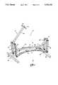
- FIG. 2is an exploded perspective view of the exercise machine of FIG. 1;
- FIG. 3is a fragmentary end view of the machine of FIG. 1 showing connection of an oscillator to the frame of the machine;
- FIG. 4fragmentary diagrammatic view of the FIG. 1 machine illustrating the foot positions of a user when simulating a perambulatory movement
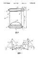
- FIG. 5is a perspective view of a further embodiment of an exercise machine according to the invention in which the rear-end of each oscillator is non-pivotally suspended from the frame and the front-end is suspended by coil springs;
- FIG. 6is a perspective view of another embodiment of an exercise machine according to the invention in which the front-end of each oscillator is non-pivotally suspended from the frame;
- FIG. 7is a perspective view of yet another embodiment of an exercise machine according to the invention wherein the oscillators are suspended by ball joints from the frame;
- FIG. 8is a perspective view of still another embodiment of an exercise machine according to the invention incorporating handles attached to the oscillators.
- FIG. 1an exercise machine 10 embodying various features of the present invention for simulating perambulatory movement.
- the machine 10includes a frame 12, a pair of oscillators 14 and 16, a pair of foot supports 18 and 20 located on the oscillators, a front left-hand oscillator support 22, a front right-hand oscillator support 24, a rear left-hand oscillator support 26, and a rear right-hand oscillator support 28.
- a userplaces a foot in each foot support 18, 20 and exerts force on the oscillators 14, 16 by moving the legs in a step path corresponding to the desired manner of perambulation.
- the forces supplied to the oscillators by the userare resisted by the oscillators as the oscillators are moved in a path which corresponds to the step path.
- walkingmay be simulated by moving the legs as if walking on solid ground.
- the oscillatorsreact to the walking motion by flexing and pivoting in a direction which corresponds generally to the walking motion and thus simulates the perambulatory movement of walking. Because the oscillators flex and pivot in a direction which corresponds to the desired perambulation, the machine allows simulation of a wide range of perambulatory movements.
- the frame 12provides an elevated support for suspending the oscillators 14 and 16 in a generally horizontal orientation spaced above a support surface S on which the frame rests so that the surface does not interfere with movement of the oscillators.
- the frame 12includes a spine member 30 which is disposed generally horizontally with respect to the ground and is supported a desired distance above the ground by a front T-shaped support 32 and a rear T-shaped support 34.
- the front support 32is connected, such as by welding, to a front end F of the spine 30 and the rear support 34 is connected to a rear end R of the spine.
- a front support post 36extends upwardly and generally forwardly from the front end F of the spine 30 and may include a pair of threaded openings 38 and 40 on opposite sides thereof for mounting of the front oscillator supports 22 and 24 thereon.
- a rear support post 42extends upwardly from the rear end R of spine member 30 and may also include a pair of threaded openings 44 and 46 on opposite sides thereof for mounting the rear oscillator supports 26 and 28 thereon.
- a handle support 48extends upwardly from the upper end of the front support post 36 in a generally rearward direction.
- a pair of hand grips 50 and 52extend outwardly from opposite sides of the handle support 48 adjacent the upper end of the support 48 for being gripped by the hands of the user during exercise. It is noted that the length/angular dimensions of the support post 36 and handle support 48 are preferably such that the handle grips 50 and 52 are positioned in space for being gripped by the user with the arms of the user forwardly disposed from a generally upright standing position.
- the T-shaped supports 32 and 34support the member 30 a desired distance above the ground so that the movement of the oscillators is not encumbered by the underlying support surface.
- the T-shaped membersprovide stability to the frame so that the frame does not rock or otherwise move during exercise.
- the front T-shaped support 32is provided by a leg 54 which extends upwardly in a generally rearward direction from a cross member 56 and connects to the front end F of spine member 30 at an angle of about 135° with respect to the spine member.
- the cross-member 56is disposed along the support surface S, such as a floor, perpendicular to the spine 30 with its midpoint generally vertically aligned with the spine 30 and immediately below the upper end of the support post 36.
- the rear T-shaped support 34is provided by a leg 58 which extends upwardly and forwardly from a cross-member 60 and connects to the rear end R of the spine 30 at an angle of about 135° with respect to the spine so that legs 54 and 58 are at about a 90° angle with respect to each other and the plane containing the legs 54, 58 and spine member 30 is substantially vertical and bisects the right and left halves of the device.
- the cross-member 60is disposed along the support surface S perpendicular to the spine 30 with its midpoint generally vertically aligned with the spine 30 and immediately below the upper end of the support post 42.
- each oscillator 14 and 16are preferably provided by upwardly arched elongate strips formed of a resiliently deformable material such as spring steel so that the oscillators are internally biased against downward deflection and resiliently deflect downwardly in response to forces applied by the user through foot supports 18 and 20, and then spring back or elevate the supports 18 or 20 when the force is relaxed.
- each oscillator 14 and 16may be provided by a leaf spring of the type commonly used in automobile suspensions and aligned in the assembled machine so that the bow or curvature of each leaf spring in the relaxed state is upwards or convex with respect to the ground.
- the oscillatorsmay be formed of composite materials such as fiberglass and may also be externally biased, as by springs, to resist deflection.
- the foot supports 18 and 20maintain the feet of the user in contact with the upper surface of the oscillators 14 and 16 and are generally fixedly positioned, such as by screws, to the oscillators at about the longitudinal midpoint.
- Suitable foot supportsinclude elastic webbing or plastic shoe-shaped receptacles attached to the oscillators to fittingly receive the front end of the shoe or foot of the user.
- the foot supportsare preferably adjustable, as by adjustment straps having mating hook and loop material, so as to be adjustable to fit different shoe sizes.
- the foot supportsmay be provided by ski bindings which receive a ski boot.
- the oscillatorsare further aligned in the assembled machine 10 to be generally parallel to the spine 30 so that one end of each oscillator is adjacent the front end F and the other end of each oscillator is adjacent the rear end R. Accordingly, the front oscillator supports 22 and 24 support the front ends of the oscillators 14 and 16, respectively, and the rear oscillator supports 26 and 28 support the rear ends of the oscillators 14 and 16, respectively.
- the front left-hand oscillator support 22, shown in detail in FIG. 3,includes a pair of elongate links 62 and 64, a spacer sleeve 66, a bushing 68, a pair of upper and lower bolts 70 and 72, respectively, and a nut 74.
- the front right-hand oscillator support 24includes a pair of elongate links 76 and 78, a spacer sleeve 80, a bushing 82, a pair of upper and lower bolts 84 and 86, respectively, and a nut 88.
- the front left-hand oscillator support 22supports the front end of the oscillator 14.
- the links 62 and 64 of the support 22are spaced apart and positioned on opposite sides of the front end of the oscillator 14 so that their lengths are generally perpendicular to the length of the oscillator when the oscillator is at rest.
- the front end of the oscillator 14includes an opening 90 which extends across the width of the oscillator and lower openings 92 and 94 in the links 62 and 64 are aligned relative to the opening 90.
- the shaft of the bolt 72is received through the opening 90 and the openings 92 and 94 and is secured in place by the nut 74 so as to allow free pivotal movement of links 62 and 64 in relation to oscillator 14.
- links 62, 64are pivotally connected to support post 36 as by bolt 70, the threaded end of which is tightened into threaded opening 38 in the post adjacent the upper end of the post.
- the head end of the boltis adjacent outer link 62, and its shaft is received through an upper opening 96 in link 62, the opening of spacer 66 separating the upper ends of links 62 and 64, an upper opening 98 in inner link 64, and an opening in bushing 68 located between inner link 64 and post 36 where upon the threaded end passes into threaded opening 38 in the post.
- the arrangementis such that upon tightening the bolt 70, the links 62, 64 are relatively freely rotatable on the bolt.
- links 62, 64support the front end of oscillator 14 in a depending fashion on frame 12 for forward and rearward oscillatory movement as the upper ends of links 62, 64 rotate on the shaft of bolt 70 and the lower ends of links 62, 64 rotate on the shaft of bolt 72.
- the front right-hand oscillator support 24supports the front end of the oscillator 16.
- the links 76 and 78 of the support 24are spaced apart and positioned on opposite sides of the front end of the oscillator 16 so that their lengths are generally perpendicular to the length of the oscillator when the oscillator is at rest.
- the front end of the oscillator 16provides an opening 100 which extends across the width of the oscillator and lower openings 102 and 104 in the links 76 and 78 are aligned relative to the opening 100.
- the shaft of the bolt 86is received through the opening 100 and the openings 102 and 104 and is secured in place by the nut 88 so as to allow free pivotal movement of links 76 and 78 in relation to oscillator 16.
- links 76, 78are pivotally connected to support post 36 as by the bolt 84, the threaded end of which is tightened into threaded opening 40 in the post 36 adjacent the upper end of the post.
- the head end of the boltis adjacent outer link 78, and its shaft is received through an upper opening 108 in link 78, the opening of spacer 80 separating the upper ends of links 76 and 78, an upper opening 106 in inner line 76, and an opening in bushing 82 located between inner link 76 and post 36 where upon the threaded end passes into threaded opening 40 in the post.
- the arrangementis such that upon tightening the bolt 84, the links 76, 78 are relatively freely rotatable on the bolt.
- links 76, 78support the front end of oscillator 16 in a depending fashion on frame 12 for forward and rearward oscillatory movement as the upper ends of links 76, 78 rotate on the shaft of bolt 84 and the lower ends of links 76, 78 rotate on the shaft of bolt 86.
- the rear left-hand oscillator support 26includes a pair of elongate links 110 and 112, a spacer sleeve 114, a bushing 116, a pair of bolts 118 and 120, and a nut 122.
- the right-hand rear oscillator support 28includes a pair of elongate links 124 and 126, a spacer sleeve 128, a bushing 130, a pair of bolts 132 and 134, and a nut 136.
- the rear left-hand oscillator support 26supports the rear end of the oscillator 14.
- the links 110 and 112 of the support 26are spaced apart and positioned on opposite sides of the rear end of the oscillator 14 so that their lengths are generally perpendicular to the length of the oscillator when the oscillator is at rest.
- the rear end of the oscillator 14provides an opening 138 which extends across the width of the oscillator and lower openings 140 and 142 in the links 110 and 112 are aligned relative to the opening 138.
- the shaft of the bolt 120is received through the opening 138 and the openings 140 and 142 and is secured in place by the nut 122 so as to allow free pivotal movement of links 110 and 112 in relation to oscillator 16.
- links 110,112are pivotally connected to support post 42 as by the bolt 118, the threaded end of which is tightened into threaded opening 44 in the post 42 adjacent the upper end of the post.
- the head end of the boltis adjacent outer link 110, and its shaft is received through an upper opening 144 in link 110, the opening of spacer 114 separating the upper ends of links 110 and 112, an upper opening 146 in inner link 112, and an opening in bushing 114 located between inner link 112 and post 42 where upon the threaded end passes into threaded opening 44 in the post.
- the arrangementis such that upon tightening the bolt 118, the links 110, 112 are relatively freely rotatable on the bolt.
- links 110,112support the front end of oscillator 14 in a depending fashion on frame 12 for forward and rearward oscillatory movement as the upper ends of links 110, 112 rotate on the shaft of bolt 118 and the lower ends of links 110, 112 rotate on the shaft of bolt 120.
- the rear right-hand oscillator support 28support the rear end of the oscillator 16.
- the links 124 and 126 of the support 28are spaced apart and positioned on opposite sides of the front end of the oscillator 16 so that their lengths are generally perpendicular to the length of the oscillator when the oscillator is at rest.
- the rear end of the oscillator 16provides an opening 148 which extends across the width of the oscillator and lower openings 150 and 152 in the links 124 and 126 are aligned relative to the opening 148.
- the shaft of the bolt 134is received through the opening 148 and the openings 150 and 152 and is secured in place by the nut 136 so as to allow free pivotal movement of links 124 and 126 in relation to oscillator 16.
- links 124, 126are pivotally connected to support post 42 as by the bolt 132, the threaded end of which is tightened into threaded opening 46 in the post adjacent the upper end of the post.
- the head end of the boltis adjacent outer link 126, and its shaft is received through an upper opening 156 in link 126, the opening of spacer 128 separating the upper ends of links 124 and 126, an upper opening 154 in inner link 124, and an opening in bushing 128 located between inner link 124 and post 42 where upon the threaded end passes into threaded opening 46 in the post.
- the arrangementis such that upon tightening the bolt 134, the links 124, 126 are relatively freely rotatable on the bolt.
- links 124, 126support the rear end of oscillator 16 in a depending fashion on frame 12 for forward and rearward oscillatory movement as the upper ends of links 124, 126 rotate on the shaft of bolt 138 and the lower ends of links 124, 126 rotate on the shaft of bolt 134.
- the oscillator supportsmay be otherwise supported by the frame.
- the threaded openings 38 and 40may be replaced by an opening which extends through the width of the support post 36 to fittingly receive a rod of sufficient length so that free ends of the rod are provided on either side of the support post to receive the links, spacer sleeves, and bushings of the front supports.
- Cotter pinsmay be passed through apertures in the free ends of the rod to maintain the supports thereon.
- each oscillatoris provided by a resiliently deformable material of the type which is internally biased to be flexible in a direction perpendicular to its length upon application of a force and which is capable of returning to its original shape after a removal of the force.
- the oscillatorsare provided by automobile-type leaf springs, however, it is intended that many different materials and structures may be used to provide the oscillators performing equivalent functions.
- the oscillatorsare therefore capable of flexing and pivoting in a manner which replicates the perambulation simulated by the user, as will be explained more fully below.
- the oscillatorsare preferably selected to have sufficient stiffness so that they remain in the substantially unflexed position when supporting the still weight of the user, but resiliently deform in accordance with and conforming to foot movements of the user associated with perambulation.
- the userstands on the oscillators 14 and 16 and the feet of the user are positioned in the foot supports 18 and 20 so that the user is standing on the oscillators straddling the frame member 30.
- the userperforms the desired perambulatory movements and the oscillators flex and move in response to the movements.
- the oscillatorsflex in a path generally perpendicular to their length and move in a path generally parallel to their length so that the foot supports oscillate in generally parallel side-by-side paths which correspond to the path of the feet of the user during exercise.
- the foot supportsoscillate in generally parallel side-by-side paths which correspond to the path of the feet of the user during exercise.
- Thisallows a variety of perambulatory movements, such as those associated with walking, jogging, running, skiing and jumping, to be simulated on the machine 10.
- the feet of the userwould be moved in step paths as if walking on the ground, as shown in FIG. 4 which diagrammatically depicts various positions of a foot 160 of the user when simulating walking on the machine.
- the foottypically has a sequential range of motion as indicated by foot positions X, Y, and Z.
- Position Xrepresents the starting position of the foot.
- the oscillator 14may be slightly flexed in the direction of the arrow A since it is supporting the still weight of the user and the supports 22 and 26, as represented by the links 62 and 110, respectively, are in a substantially unpivoted orientation with respect to the frame.
- the footthen travels forward to foot position Y, which represents the position of the foot during the walking motion when the foot is substantially in front of the body of the user.
- the links 62 and 110are pivoted clockwise as shown by the arrow B and the oscillator is substantially deformed or flattened.
- the swing or pivot of the oscillator supportselevates the front end and rear end of the oscillator a distance D above the starting position.
- foot position Zwhich represents the position of the foot during the walking motion when the foot is substantially behind the body of the user.
- the links 62 and 110are pivoted counter-clockwise as shown by the arrow C and the oscillator is substantially unflexed with the front end and rear end elevated a distance E above the starting position. It will be appreciated that many variations of this movement cycle are possible. For example, the use may flex the oscillator in position X and allow it to relax in position Y and/or Z.
- FIG. 5shows an embodiment illustrating a machine where the front end of each oscillator is suspended from a frame by a coil spring and the rear end of each oscillator is supported by a rod which is welded to the frame.
- Elements of this embodiment corresponding to elements of the embodiment 10 previously describedwill be referenced with the same characters using a prime suffix.
- the exercise machine designated 10'consists of a frame 12' having a spine 30', a pair of oscillators 14' and 16' having foot supports 18' and 20', front oscillator supports 22' and 24', rear oscillator supports 26' and 28', and handles 50' and 52'.
- This embodimentis particularly well adapted for simulating jumping or marching-in-place movements.
- the front left hand oscillator support 22'includes an elongate coil spring 162 supported by a loop or hanger 164 attached to the frame 12'.
- the hanger 164is attached at its upper end, such as by welding, to a cross-member 165 of the frame which extends between the handles 50', 5240 at the front end F' of the frame above a cross-member 56' which rests lengthwise on the surface S' perpendicular to the spine 30'.
- the lower end of the hanger 164attaches to the upper end of the coil spring.
- the lowermost coil of the coil spring 162engagingly receives the left-end of a rod 166 which extends through an opening 90' in the front end of the oscillator 14'.
- the right-end of the rod 166extends through an opening 100' in the front end of the oscillator 16' so 10 that the rod 166 extends between the front ends of the oscillators 14', 16'.
- the front right-hand oscillator support 24'likewise includes a coil spring 168 supported by a hanger 170, with the hanger supporting one end of the spring 168 and the lowermost coil of the coil spring 168 receiving the right-end of the rod 166 as stated above.
- the rear left-hand oscillator support 26'includes a rod 172 welded to the left side of a support post 42' which extends upwardly from a cross-member 60' at the rear end R' of the frame 12'.
- the rod 172extends through an opening 138' in the rear end of the oscillator 14'.
- a cotter pin(not shown) may be inserted into an opening provided through the free end of the rod 172 for maintaining the oscillator on the rod 172.
- the rear right-hand oscillator support 28'is provided by a rod 174 welded to the right side of the support 42', the rod 174 extending through an opening 148' in the rear end of the oscillator 16'.
- the front oscillator supports 22' and 24'allow limited horizontal movement of the front end of each oscillator and the coil springs dampen or soften the vertical motion of the oscillators.
- the horizontal movementis limited to the horizontal elongation of the oscillators resulting from their deformation in response to force exerted by the user.
- the rear osciallator supportsretain the rear end of the oscillators in a fixed position so that elongation as a result of deformation, i.e. forward and rearward motion, is realized at the front end of the oscillators.
- FIG. 6A further embodiment of the invention is illustrated in FIG. 6 where the front end of each oscillator is connected to a frame by a rod which is welded to the frame and the rear end of each oscillator is pivotally suspended from the frame in the same manner as are the oscillators of the embodiment 10.
- the exercise machine designated 10consists of a frame 12" having a spine 30", a pair of oscillators 14" and 16" having foot supports 18" and 20", front oscillator supports 22" and 24", rear oscillator supports 26" and 28", and handles 50" and 52".
- the front left-hand oscillator support 22"includes a rod 176 welded to the left side of a support post 36" which extends upwardly from a cross-member 56" at the front end F" of the frame 12" which rests lengthwise on the support surface S" perpendicular to the spine 30".
- the rod 176extends through an opening 90" in the front end of the oscillator 14".
- a cotter pin(not shown) may be inserted into an opening provided through the free end of the rod 176 for maintaining the oscillator on the rod 176.
- the front right-hand oscillator support 24"is provided by a rod 178 welded to the right side of the support 36", the rod 178 extending through an opening 100" in the rear end of the oscillator 16".
- the front oscillator supports 22", 24"retain the front end of the oscillators 14", 16" in a fixed position so that elongation as a result of deformation is realized at the rear end of the oscillators.
- the rear oscillator supports 26" and 28"are suspended form a support post 42" which extends upwardly from a cross-member 60" at the rear end R" of the frame 12".
- the supports 26" and 28"are identical to the supports 26 and 28 described in accordance with embodiment 10, and pivot in response to deformation and relaxation of the oscillators 14" and 16" in the same manner as described for embodiment 10.
- FIG. 7A still further embodiment of the invention is illustrated FIG. 7 where front and rear oscillator supports are suspended from the frame by ball joints. Elements of this embodiment corresponding to elements of the embodiment 10 previously described will be referenced with the same characters using a triple prime suffix.
- the exercise machine designated 10"'consists of a frame 12"', a pair of oscillators 14"' and 16"' having foot supports 18"' and 20"', front oscillator supports 22"' and 24"', rear oscillator supports 26"' and 28"', and handles 50"' and 52"' after the manner of ski poles.
- This embodimentis particularly well adapted for simulating cross-country and downhill skiing since the oscillators may also move in a side-to-side rocking fashion in addition to side-by-side gliding and flexing so that three-dimensional step paths may be simulated with lateral, longitudinal and vertical variations.
- the frame 12"'includes a pair of spaced apart and side-by-side spines 30"' supported a distance above the support surface by generally "V"-shaped legs 180, one of which is provided at each end of each spine 30".
- a cross-member 56"'spans between the front-ends of the spines and is supported above the spines by a pair of posts 36"' extending upwardly and inwardly from the legs 180 at the front end.
- a cross-member 60"'spans between the rear-ends of the spines and is supported above the spines by a pair of posts 42"' extending upwardly and inwardly from the legs 180 at the rear end.
- the oscillators 14"' and 16"'are suspended between the spines 30"' rather than on opposite sides of a central spine.
- the front left-hand oscillator support 22"'includes a pair of elongate links 62"' and 64"' and the lower end of the oscillator support 22"' may be identical to the lower end of the support 22 of embodiment 10.
- the upper end of the support 22"'includes a ball joint 182.
- the links 62"' and 64"'attach to opposite sides of a base 184 of the ball joint, such as by welding, to enable rotation of the support 22"' about its length axis and pivotal movement of the support in an orbital fashion relative to the frame to provide an expanded range of foot positions of the user's feet during simulation of perambulatory movement.
- the ball joint 182includes a ball 186 welded to the base 184 and a cylindrical housing 188 formed on a sleeve 190.
- the ballis engagingly received within the housing 188.
- the sleeve 190includes an opening 202 extending through the length thereof and sized to slide over a rod 204.
- the rod 204extends parallel to the cross-member 56"' and is attached to the cross-member by blocks 205 which are welded to the cross-member and have openings therethrough for fittingly receiving the rod 204.
- the handle 50"'extends upwardly from the base 184 for grasping by the left hand of the user. Alternatively, the handle 50"' may be attached, as by releasable clips or by welding, to the block 205 above the base 184.
- the remaining supports 24"', 26"" and 28"'are preferably identical to the support 22"', except the rear supports 26"' and 28"' are suspended from a rod 206 attached to the cross-member 60"' in the same manner as the rod 204 is attached to the cross-member 56"'.
- FIG. 8Still another embodiment of the invention is illustrated in FIG. 8. Elements of this embodiment corresponding to elements of the embodiment 10 previously described will be referenced with the same characters using a quadruple prime suffix.
- This embodimentis identical in construction to the embodiment 10, except that the handle support 48 and the hand grips 50 and 52 have been removed and replaced with elongate poles 210 and 212 which are releasably connected at their lower ends, as by clips or holders 213 attached, as by welding to the spacer sleeves 66 and 80.
- this embodiment 10"it will be appreciated that force may be transmitted to the oscillators by the user through leg movement and by exertion of force on the handles.
- the usermay also pull and push on the handles to exaggerate the pivotal motion of the oscillators on the oscillator supports. In this manner, the user may extend his stride length beyond that which would normally be experienced and also exercise upper body muscles.
- the poles 210 and 212may be removed and the handle support 48 with hand grips 50 and 52 attached, as by bolts, to the support post to return the machine to the configuration of embodiment 10.
Landscapes
- Health & Medical Sciences (AREA)
- Cardiology (AREA)
- Vascular Medicine (AREA)
- General Health & Medical Sciences (AREA)
- Physical Education & Sports Medicine (AREA)
- Percussion Or Vibration Massage (AREA)
Abstract
Description
Claims (34)
Priority Applications (1)
| Application Number | Priority Date | Filing Date | Title |
|---|---|---|---|
| US07/951,672US5336141A (en) | 1992-09-25 | 1992-09-25 | Exercise machine for simulating perambulatory movement |
Applications Claiming Priority (1)
| Application Number | Priority Date | Filing Date | Title |
|---|---|---|---|
| US07/951,672US5336141A (en) | 1992-09-25 | 1992-09-25 | Exercise machine for simulating perambulatory movement |
Publications (1)
| Publication Number | Publication Date |
|---|---|
| US5336141Atrue US5336141A (en) | 1994-08-09 |
Family
ID=25491992
Family Applications (1)
| Application Number | Title | Priority Date | Filing Date |
|---|---|---|---|
| US07/951,672Expired - LifetimeUS5336141A (en) | 1992-09-25 | 1992-09-25 | Exercise machine for simulating perambulatory movement |
Country Status (1)
| Country | Link |
|---|---|
| US (1) | US5336141A (en) |
Cited By (69)
| Publication number | Priority date | Publication date | Assignee | Title |
|---|---|---|---|---|
| US5575740A (en)* | 1993-09-30 | 1996-11-19 | Piaget; Gary D. | Striding exerciser with upwardly curved tracks |
| US5605521A (en)* | 1996-02-15 | 1997-02-25 | Lifegear, Inc. | Striding exerciser |
| US5613924A (en)* | 1996-04-05 | 1997-03-25 | Lee; Sunny | Body exerciser |
| WO1997021470A1 (en)* | 1995-12-14 | 1997-06-19 | Husted Royce Hill | Low impact simulated striding device |
| US5683330A (en)* | 1995-12-11 | 1997-11-04 | The University Of Tokyo | Sprint training machine |
| USD390628S (en) | 1996-10-24 | 1998-02-10 | Husted Royce H | Striding device |
| USD391610S (en) | 1996-10-24 | 1998-03-03 | Husted Royce H | Striding device |
| USD392005S (en) | 1997-02-13 | 1998-03-10 | Piaget Gary D | Striding exercise device |
| USD392700S (en) | 1997-02-13 | 1998-03-24 | Piaget Gary D | Striding exercise device |
| USD393027S (en) | 1997-03-17 | 1998-03-31 | Chin-Chiao Chen | Walking exerciser |
| US5735778A (en)* | 1997-02-13 | 1998-04-07 | Piaget; Gary D. | Exercise apparatus including an improved upper body exercise device |
| US5785630A (en)* | 1993-02-02 | 1998-07-28 | Tectrix Fitness Equipment, Inc. | Interactive exercise apparatus |
| US5792027A (en)* | 1997-01-09 | 1998-08-11 | Kordun, Ltd. | Aerobic striding exerciser |
| US5890995A (en)* | 1993-02-02 | 1999-04-06 | Tectrix Fitness Equipment, Inc. | Interactive exercise apparatus |
| US5910072A (en)* | 1997-12-03 | 1999-06-08 | Stairmaster Sports/Medical Products, Inc. | Exercise apparatus |
| US5971892A (en)* | 1999-03-10 | 1999-10-26 | Lee; Sunny | Exerciser with combined walking and stepping functions |
| US5993357A (en)* | 1997-08-19 | 1999-11-30 | Tom; James L. | Neck exercise apparatus |
| US6004244A (en)* | 1997-02-13 | 1999-12-21 | Cybex International, Inc. | Simulated hill-climbing exercise apparatus and method of exercising |
| US6019709A (en)* | 1997-02-13 | 2000-02-01 | Piaget; Gary D. | Striding exerciser with adjustable upwardly curved tracks |
| US6030319A (en)* | 1999-04-15 | 2000-02-29 | Modas Shing Company Ltd. | Foldable cross-country skiing exerciser |
| US6036622A (en)* | 1997-10-10 | 2000-03-14 | Gordon; Joel D. | Exercise device |
| US6117052A (en)* | 1999-05-07 | 2000-09-12 | Bollinger Industries, L.P. | Aerobic exercise machine with lateral swinging capability |
| US6135926A (en)* | 1997-05-27 | 2000-10-24 | Lee; Gin Wen | Striding exerciser |
| US6165107A (en)* | 1999-03-18 | 2000-12-26 | Illinois Tool Works Inc. | Flexibly coordinated motion elliptical exerciser |
| US6302830B1 (en) | 2000-05-12 | 2001-10-16 | Kenneth W. Stearns | Exercise methods and apparatus |
| US20020165066A1 (en)* | 1997-10-07 | 2002-11-07 | Stearns Kenneth W. | Exercise methods and apparatus |
| US6689019B2 (en) | 2001-03-30 | 2004-02-10 | Nautilus, Inc. | Exercise machine |
| US20040162191A1 (en)* | 2003-02-19 | 2004-08-19 | Gaylen Ercanbrack | Cushioned elliptical exerciser |
| US20040248705A1 (en)* | 2003-06-06 | 2004-12-09 | Rodgers Robert E. | Variable path exercise apparatus |
| US20040248711A1 (en)* | 2003-06-06 | 2004-12-09 | Rodgers Robert E. | Exercise apparatus that allows user varied stride length |
| US20050049117A1 (en)* | 2003-08-29 | 2005-03-03 | Rodgers Robert E. | Striding simulators |
| US6875160B2 (en) | 2001-08-30 | 2005-04-05 | Icon Ip, Inc. | Elliptical exercise device with leaf spring supports |
| US20050245356A1 (en)* | 2004-05-03 | 2005-11-03 | Tom James L | Neck exercise apparatus |
| US20060046902A1 (en)* | 2004-09-01 | 2006-03-02 | Huang-Tung Chang | Elliptical exerciser with adjustable guiding rails |
| US7097593B2 (en) | 2003-08-11 | 2006-08-29 | Nautilus, Inc. | Combination of treadmill and stair climbing machine |
| US7169088B2 (en) | 2003-06-06 | 2007-01-30 | Rodgers Jr Robert E | Compact variable path exercise apparatus |
| US7169089B2 (en) | 2003-06-06 | 2007-01-30 | Rodgers Jr Robert E | Compact variable path exercise apparatus with a relatively long cam surface |
| US20070027009A1 (en)* | 2005-07-30 | 2007-02-01 | Precor Incorporated | Exercise device having a movable platform |
| US7172531B2 (en) | 2003-06-06 | 2007-02-06 | Rodgers Jr Robert E | Variable stride exercise apparatus |
| US20070037667A1 (en)* | 2005-08-11 | 2007-02-15 | Gordon Joel D | Exercise device |
| US7201705B2 (en) | 2003-06-06 | 2007-04-10 | Rodgers Jr Robert E | Exercise apparatus with a variable stride system |
| US20080020905A1 (en)* | 2006-07-24 | 2008-01-24 | Dream Visions, Llc | Adjustable foot support platform for an exercise apparatus |
| US20080167164A1 (en)* | 2007-01-04 | 2008-07-10 | P & F Brother Industrial Corporation | Elliptical machine |
| US20080214364A1 (en)* | 2006-10-30 | 2008-09-04 | Maresh Joseph D | Ellipical exercise apparatus with flexible unitary force imparting member |
| US20080280731A1 (en)* | 2007-05-08 | 2008-11-13 | Icon Health & Fitness, Inc. | Elliptical exercise machine with adjustable foot motion |
| US20090011904A1 (en)* | 2007-07-06 | 2009-01-08 | Jin Chen Chuang | Elliptical exercise device |
| US7517303B2 (en) | 2003-02-28 | 2009-04-14 | Nautilus, Inc. | Upper body exercise and flywheel enhanced dual deck treadmills |
| US7618350B2 (en) | 2007-06-04 | 2009-11-17 | Icon Ip, Inc. | Elliptical exercise machine with adjustable ramp |
| US7628734B1 (en)* | 2004-01-14 | 2009-12-08 | Richard Proctor | Exercising and physiotherapy system |
| US7658698B2 (en) | 2006-08-02 | 2010-02-09 | Icon Ip, Inc. | Variable stride exercise device with ramp |
| US7717828B2 (en) | 2006-08-02 | 2010-05-18 | Icon Ip, Inc. | Exercise device with pivoting assembly |
| US7736279B2 (en) | 2007-02-20 | 2010-06-15 | Icon Ip, Inc. | One-step foldable elliptical exercise machine |
| US7740563B2 (en) | 2004-08-11 | 2010-06-22 | Icon Ip, Inc. | Elliptical exercise machine with integrated anaerobic exercise system |
| US7766797B2 (en) | 2004-08-11 | 2010-08-03 | Icon Ip, Inc. | Breakaway or folding elliptical exercise machine |
| US8409058B2 (en) | 2006-08-10 | 2013-04-02 | Exerciting, Llc | Varied gait exercise device with pivot bar transfer system |
| CN103252060A (en)* | 2013-05-27 | 2013-08-21 | 南京万德游乐设备有限公司 | Skiing bodybuilding equipment |
| USD742977S1 (en) | 2013-08-29 | 2015-11-10 | Octane Fitness, Llc | Stationary exercise machine |
| US9364708B2 (en) | 2013-08-29 | 2016-06-14 | Octane Fitness, Llc | Lower body mimetic exercise device with fully or partially autonomous right and left leg links and ergonomically positioned pivot points |
| US9993680B2 (en) | 2014-12-10 | 2018-06-12 | Fit-Novation, Inc. | Exercise device |
| US10046197B2 (en) | 2015-11-19 | 2018-08-14 | Fitnovation, Inc. | Exercise device |
| US10369404B2 (en) | 2015-12-31 | 2019-08-06 | Nautilus, Inc. | Pedal assembly for exercise machine |
| US10493349B2 (en) | 2016-03-18 | 2019-12-03 | Icon Health & Fitness, Inc. | Display on exercise device |
| US10625114B2 (en) | 2016-11-01 | 2020-04-21 | Icon Health & Fitness, Inc. | Elliptical and stationary bicycle apparatus including row functionality |
| US10625137B2 (en) | 2016-03-18 | 2020-04-21 | Icon Health & Fitness, Inc. | Coordinated displays in an exercise device |
| US11000731B2 (en)* | 2017-07-12 | 2021-05-11 | Motiofy Ab | Cross-country skiing machine |
| US11191995B2 (en) | 2016-12-30 | 2021-12-07 | Nautilus, Inc. | Pedal assembly for exercise machine |
| US12185836B1 (en) | 2022-07-19 | 2025-01-07 | Ronald B. Johnson | Height adjustable desk |
| US12268930B1 (en) | 2022-07-19 | 2025-04-08 | Ronald B. Johnson | Body motion office work platform |
| US12376674B1 (en) | 2023-03-29 | 2025-08-05 | Ronald B. Johnson | Seat incorporated into desk platform |
Citations (5)
| Publication number | Priority date | Publication date | Assignee | Title |
|---|---|---|---|---|
| US3824994A (en)* | 1973-01-29 | 1974-07-23 | R S Reciprocating Trainer Ente | Reciprocating walker |
| US4492374A (en)* | 1981-04-21 | 1985-01-08 | David Lekhtman | Sporting and exercising spring shoe |
| US4850585A (en)* | 1987-09-08 | 1989-07-25 | Weslo, Inc. | Striding exerciser |
| US4861023A (en)* | 1987-07-31 | 1989-08-29 | Mike Wedman | Leg muscle exercise device and method |
| US4880226A (en)* | 1989-02-21 | 1989-11-14 | Peter Krantz | Skiing simulator |
- 1992
- 1992-09-25USUS07/951,672patent/US5336141A/ennot_activeExpired - Lifetime
Patent Citations (5)
| Publication number | Priority date | Publication date | Assignee | Title |
|---|---|---|---|---|
| US3824994A (en)* | 1973-01-29 | 1974-07-23 | R S Reciprocating Trainer Ente | Reciprocating walker |
| US4492374A (en)* | 1981-04-21 | 1985-01-08 | David Lekhtman | Sporting and exercising spring shoe |
| US4861023A (en)* | 1987-07-31 | 1989-08-29 | Mike Wedman | Leg muscle exercise device and method |
| US4850585A (en)* | 1987-09-08 | 1989-07-25 | Weslo, Inc. | Striding exerciser |
| US4880226A (en)* | 1989-02-21 | 1989-11-14 | Peter Krantz | Skiing simulator |
Cited By (108)
| Publication number | Priority date | Publication date | Assignee | Title |
|---|---|---|---|---|
| US5785630A (en)* | 1993-02-02 | 1998-07-28 | Tectrix Fitness Equipment, Inc. | Interactive exercise apparatus |
| US5890995A (en)* | 1993-02-02 | 1999-04-06 | Tectrix Fitness Equipment, Inc. | Interactive exercise apparatus |
| US5575740A (en)* | 1993-09-30 | 1996-11-19 | Piaget; Gary D. | Striding exerciser with upwardly curved tracks |
| US5683330A (en)* | 1995-12-11 | 1997-11-04 | The University Of Tokyo | Sprint training machine |
| AU707555B2 (en)* | 1995-12-14 | 1999-07-15 | Royce H. Husted | Low impact simulated striding device |
| WO1997021470A1 (en)* | 1995-12-14 | 1997-06-19 | Husted Royce Hill | Low impact simulated striding device |
| US5795268A (en)* | 1995-12-14 | 1998-08-18 | Husted; Royce H. | Low impact simulated striding device |
| US5857940A (en)* | 1995-12-14 | 1999-01-12 | Husted; Royce H. | Low impact simulated striding device |
| US5681244A (en)* | 1996-02-15 | 1997-10-28 | Lifegear, Inc. | Striding exerciser |
| US5605521A (en)* | 1996-02-15 | 1997-02-25 | Lifegear, Inc. | Striding exerciser |
| US5613924A (en)* | 1996-04-05 | 1997-03-25 | Lee; Sunny | Body exerciser |
| USD390628S (en) | 1996-10-24 | 1998-02-10 | Husted Royce H | Striding device |
| USD391610S (en) | 1996-10-24 | 1998-03-03 | Husted Royce H | Striding device |
| US5792027A (en)* | 1997-01-09 | 1998-08-11 | Kordun, Ltd. | Aerobic striding exerciser |
| USD392005S (en) | 1997-02-13 | 1998-03-10 | Piaget Gary D | Striding exercise device |
| US6004244A (en)* | 1997-02-13 | 1999-12-21 | Cybex International, Inc. | Simulated hill-climbing exercise apparatus and method of exercising |
| US5735778A (en)* | 1997-02-13 | 1998-04-07 | Piaget; Gary D. | Exercise apparatus including an improved upper body exercise device |
| US6019709A (en)* | 1997-02-13 | 2000-02-01 | Piaget; Gary D. | Striding exerciser with adjustable upwardly curved tracks |
| USD392700S (en) | 1997-02-13 | 1998-03-24 | Piaget Gary D | Striding exercise device |
| USD393027S (en) | 1997-03-17 | 1998-03-31 | Chin-Chiao Chen | Walking exerciser |
| US6135926A (en)* | 1997-05-27 | 2000-10-24 | Lee; Gin Wen | Striding exerciser |
| US5993357A (en)* | 1997-08-19 | 1999-11-30 | Tom; James L. | Neck exercise apparatus |
| US20020165066A1 (en)* | 1997-10-07 | 2002-11-07 | Stearns Kenneth W. | Exercise methods and apparatus |
| US7201704B2 (en)* | 1997-10-07 | 2007-04-10 | Stearns Kenneth W | Exercise methods and apparatus |
| US7226390B2 (en)* | 1997-10-07 | 2007-06-05 | Stearns Kenneth W | Exercise methods and apparatus |
| US20050079958A1 (en)* | 1997-10-07 | 2005-04-14 | Stearns Kenneth W. | Exercise methods and apparatus |
| US6036622A (en)* | 1997-10-10 | 2000-03-14 | Gordon; Joel D. | Exercise device |
| US5910072A (en)* | 1997-12-03 | 1999-06-08 | Stairmaster Sports/Medical Products, Inc. | Exercise apparatus |
| US5971892A (en)* | 1999-03-10 | 1999-10-26 | Lee; Sunny | Exerciser with combined walking and stepping functions |
| US6165107A (en)* | 1999-03-18 | 2000-12-26 | Illinois Tool Works Inc. | Flexibly coordinated motion elliptical exerciser |
| US6030319A (en)* | 1999-04-15 | 2000-02-29 | Modas Shing Company Ltd. | Foldable cross-country skiing exerciser |
| US6117052A (en)* | 1999-05-07 | 2000-09-12 | Bollinger Industries, L.P. | Aerobic exercise machine with lateral swinging capability |
| US6302830B1 (en) | 2000-05-12 | 2001-10-16 | Kenneth W. Stearns | Exercise methods and apparatus |
| US20110218079A1 (en)* | 2001-03-30 | 2011-09-08 | Nautilus, Inc. | Exercise machine |
| US10201727B2 (en) | 2001-03-30 | 2019-02-12 | Nautilus, Inc. | Exercise machine |
| US6689019B2 (en) | 2001-03-30 | 2004-02-10 | Nautilus, Inc. | Exercise machine |
| US7341542B2 (en) | 2001-03-30 | 2008-03-11 | Nautilus, Inc. | Exercise machine |
| US8323155B2 (en) | 2001-03-30 | 2012-12-04 | Nautilus, Inc. | Exercise machine |
| US8858403B2 (en) | 2001-03-30 | 2014-10-14 | Nautilus, Inc. | Exercise machine |
| US7942787B2 (en) | 2001-03-30 | 2011-05-17 | Nautilus, Inc. | Exercise machine |
| US9272182B2 (en) | 2001-03-30 | 2016-03-01 | Nautilus, Inc. | Exercise machine |
| US6875160B2 (en) | 2001-08-30 | 2005-04-05 | Icon Ip, Inc. | Elliptical exercise device with leaf spring supports |
| US7425188B2 (en) | 2003-02-19 | 2008-09-16 | Gaylen Ercanbrack | Cushioned elliptical exerciser |
| US7169087B2 (en) | 2003-02-19 | 2007-01-30 | Icon Health & Fitness, Inc. | Cushioned elliptical exerciser |
| US20040162191A1 (en)* | 2003-02-19 | 2004-08-19 | Gaylen Ercanbrack | Cushioned elliptical exerciser |
| US20070123394A1 (en)* | 2003-02-19 | 2007-05-31 | Gaylen Ercanbrack | Cushioned elliptical exerciser |
| US7517303B2 (en) | 2003-02-28 | 2009-04-14 | Nautilus, Inc. | Upper body exercise and flywheel enhanced dual deck treadmills |
| US7214168B2 (en) | 2003-06-06 | 2007-05-08 | Rodgers Jr Robert E | Variable path exercise apparatus |
| US7169089B2 (en) | 2003-06-06 | 2007-01-30 | Rodgers Jr Robert E | Compact variable path exercise apparatus with a relatively long cam surface |
| US20040248705A1 (en)* | 2003-06-06 | 2004-12-09 | Rodgers Robert E. | Variable path exercise apparatus |
| US7179201B2 (en) | 2003-06-06 | 2007-02-20 | Rodgers Jr Robert E | Variable stride exercise apparatus |
| US20040248711A1 (en)* | 2003-06-06 | 2004-12-09 | Rodgers Robert E. | Exercise apparatus that allows user varied stride length |
| US7172531B2 (en) | 2003-06-06 | 2007-02-06 | Rodgers Jr Robert E | Variable stride exercise apparatus |
| US7244217B2 (en) | 2003-06-06 | 2007-07-17 | Rodgers Jr Robert E | Exercise apparatus that allows user varied stride length |
| US7201705B2 (en) | 2003-06-06 | 2007-04-10 | Rodgers Jr Robert E | Exercise apparatus with a variable stride system |
| US7169088B2 (en) | 2003-06-06 | 2007-01-30 | Rodgers Jr Robert E | Compact variable path exercise apparatus |
| US7097593B2 (en) | 2003-08-11 | 2006-08-29 | Nautilus, Inc. | Combination of treadmill and stair climbing machine |
| US20050049117A1 (en)* | 2003-08-29 | 2005-03-03 | Rodgers Robert E. | Striding simulators |
| US7628734B1 (en)* | 2004-01-14 | 2009-12-08 | Richard Proctor | Exercising and physiotherapy system |
| US7041033B2 (en) | 2004-05-03 | 2006-05-09 | Tom James L | Neck exercise apparatus |
| US20050245356A1 (en)* | 2004-05-03 | 2005-11-03 | Tom James L | Neck exercise apparatus |
| US7909740B2 (en) | 2004-08-11 | 2011-03-22 | Icon Ip, Inc. | Elliptical exercise machine with integrated aerobic exercise system |
| US7775940B2 (en) | 2004-08-11 | 2010-08-17 | Icon Ip, Inc. | Folding elliptical exercise machine |
| US7740563B2 (en) | 2004-08-11 | 2010-06-22 | Icon Ip, Inc. | Elliptical exercise machine with integrated anaerobic exercise system |
| US7766797B2 (en) | 2004-08-11 | 2010-08-03 | Icon Ip, Inc. | Breakaway or folding elliptical exercise machine |
| US7402126B2 (en)* | 2004-09-01 | 2008-07-22 | Huang-Tung Chang | Elliptical exerciser with adjustable guiding rails |
| US20060046902A1 (en)* | 2004-09-01 | 2006-03-02 | Huang-Tung Chang | Elliptical exerciser with adjustable guiding rails |
| US20070027009A1 (en)* | 2005-07-30 | 2007-02-01 | Precor Incorporated | Exercise device having a movable platform |
| US7374522B2 (en) | 2005-07-30 | 2008-05-20 | Precor Incorporated | Exercise device having a movable platform |
| US7645215B2 (en) | 2005-08-11 | 2010-01-12 | Gordon Joel D | Exercise device |
| US7833134B2 (en) | 2005-08-11 | 2010-11-16 | Gordon Joel D | Exercise device |
| US20100152001A1 (en)* | 2005-08-11 | 2010-06-17 | Gordon Joel D | Exercise Device |
| US20070037667A1 (en)* | 2005-08-11 | 2007-02-15 | Gordon Joel D | Exercise device |
| US20080020905A1 (en)* | 2006-07-24 | 2008-01-24 | Dream Visions, Llc | Adjustable foot support platform for an exercise apparatus |
| US7658698B2 (en) | 2006-08-02 | 2010-02-09 | Icon Ip, Inc. | Variable stride exercise device with ramp |
| US7717828B2 (en) | 2006-08-02 | 2010-05-18 | Icon Ip, Inc. | Exercise device with pivoting assembly |
| US9050491B2 (en) | 2006-08-10 | 2015-06-09 | Exerciting, Llc | Varied gait exercise device with anatomically aligned hip pivots |
| US9968824B2 (en) | 2006-08-10 | 2018-05-15 | Exerciting, Llc | Exercise device providing user defined pedal movements |
| US9682279B2 (en) | 2006-08-10 | 2017-06-20 | Exerciting, Llc | Exercise device providing user defined pedal movements |
| US8409058B2 (en) | 2006-08-10 | 2013-04-02 | Exerciting, Llc | Varied gait exercise device with pivot bar transfer system |
| US7662069B2 (en)* | 2006-10-30 | 2010-02-16 | Maresh Joseph D | Ellipical exercise apparatus with flexible unitary force imparting member |
| US8172728B2 (en)* | 2006-10-30 | 2012-05-08 | Maresh Joseph D | Elliptical exercise apparatus with flexible unitary force imparting member |
| US20100323849A1 (en)* | 2006-10-30 | 2010-12-23 | Joseph D Maresh | Elliptical Exercise Apparatus With Flexible Unitary Force Imparting Member |
| US20080214364A1 (en)* | 2006-10-30 | 2008-09-04 | Maresh Joseph D | Ellipical exercise apparatus with flexible unitary force imparting member |
| US7455623B2 (en)* | 2007-01-04 | 2008-11-25 | P & F Brother Industrial Corporation | Elliptical machine |
| US20080167164A1 (en)* | 2007-01-04 | 2008-07-10 | P & F Brother Industrial Corporation | Elliptical machine |
| US7736279B2 (en) | 2007-02-20 | 2010-06-15 | Icon Ip, Inc. | One-step foldable elliptical exercise machine |
| US7674205B2 (en) | 2007-05-08 | 2010-03-09 | Icon Ip, Inc. | Elliptical exercise machine with adjustable foot motion |
| US20080280731A1 (en)* | 2007-05-08 | 2008-11-13 | Icon Health & Fitness, Inc. | Elliptical exercise machine with adjustable foot motion |
| US7618350B2 (en) | 2007-06-04 | 2009-11-17 | Icon Ip, Inc. | Elliptical exercise machine with adjustable ramp |
| US20090011904A1 (en)* | 2007-07-06 | 2009-01-08 | Jin Chen Chuang | Elliptical exercise device |
| US7811206B2 (en)* | 2007-07-06 | 2010-10-12 | Jin Chen Chuang | Elliptical exercise device |
| CN103252060A (en)* | 2013-05-27 | 2013-08-21 | 南京万德游乐设备有限公司 | Skiing bodybuilding equipment |
| US9364708B2 (en) | 2013-08-29 | 2016-06-14 | Octane Fitness, Llc | Lower body mimetic exercise device with fully or partially autonomous right and left leg links and ergonomically positioned pivot points |
| USD742977S1 (en) | 2013-08-29 | 2015-11-10 | Octane Fitness, Llc | Stationary exercise machine |
| US10220250B2 (en)* | 2013-08-29 | 2019-03-05 | Octane Fitness, Llc | Lower body mimetic exercise device with fully or partially autonomous right and left leg links and ergonomically positioned pivot points |
| US9993680B2 (en) | 2014-12-10 | 2018-06-12 | Fit-Novation, Inc. | Exercise device |
| US10046197B2 (en) | 2015-11-19 | 2018-08-14 | Fitnovation, Inc. | Exercise device |
| US10350451B2 (en) | 2015-11-19 | 2019-07-16 | Fit-Novation, Inc. | Exercise device |
| US10369404B2 (en) | 2015-12-31 | 2019-08-06 | Nautilus, Inc. | Pedal assembly for exercise machine |
| US10493349B2 (en) | 2016-03-18 | 2019-12-03 | Icon Health & Fitness, Inc. | Display on exercise device |
| US10625137B2 (en) | 2016-03-18 | 2020-04-21 | Icon Health & Fitness, Inc. | Coordinated displays in an exercise device |
| US10625114B2 (en) | 2016-11-01 | 2020-04-21 | Icon Health & Fitness, Inc. | Elliptical and stationary bicycle apparatus including row functionality |
| US11191995B2 (en) | 2016-12-30 | 2021-12-07 | Nautilus, Inc. | Pedal assembly for exercise machine |
| US11000731B2 (en)* | 2017-07-12 | 2021-05-11 | Motiofy Ab | Cross-country skiing machine |
| US12185836B1 (en) | 2022-07-19 | 2025-01-07 | Ronald B. Johnson | Height adjustable desk |
| US12268930B1 (en) | 2022-07-19 | 2025-04-08 | Ronald B. Johnson | Body motion office work platform |
| US12376674B1 (en) | 2023-03-29 | 2025-08-05 | Ronald B. Johnson | Seat incorporated into desk platform |
Similar Documents
| Publication | Publication Date | Title |
|---|---|---|
| US5336141A (en) | Exercise machine for simulating perambulatory movement | |
| US6036622A (en) | Exercise device | |
| US4555109A (en) | Exercising machine | |
| US5967944A (en) | Cross-training exercise apparatus | |
| US5735773A (en) | Cross-training exercise apparatus | |
| EP2842610B1 (en) | Lower body mimetic exercise device with fully or partially autonomous right and left leg links and ergonomically positioned pivot points | |
| US3756595A (en) | Leg exercising device for simulating ice skating | |
| US6042510A (en) | Jumping jack exercise device | |
| US6206806B1 (en) | Elliptical motion exerciser | |
| US6117052A (en) | Aerobic exercise machine with lateral swinging capability | |
| US4900012A (en) | Leg exercising system | |
| US5792028A (en) | Running exercise machine | |
| US7780577B2 (en) | Pendulous exercise device | |
| EP1938869B1 (en) | Supplemental resistance assembly for resisting motion of an exercise device | |
| US5749811A (en) | Skiing simulator | |
| US5656003A (en) | Leg exercise apparatus | |
| US5876308A (en) | Running exercise machine | |
| US5605521A (en) | Striding exerciser | |
| US6280364B1 (en) | Method for exercising | |
| EP1210961A1 (en) | Footbed for elliptical exercise machine | |
| US5277677A (en) | Stepping exercise machine | |
| US20140155231A1 (en) | Exercise apparatus | |
| US4595195A (en) | Apparatus for practicing skiing | |
| US7137929B2 (en) | Fitness bike | |
| US20090011906A1 (en) | Rebounding exerciser |
Legal Events
| Date | Code | Title | Description |
|---|---|---|---|
| STCF | Information on status: patent grant | Free format text:PATENTED CASE | |
| FEPP | Fee payment procedure | Free format text:PAT HOLDER CLAIMS SMALL ENTITY STATUS - SMALL BUSINESS (ORIGINAL EVENT CODE: SM02); ENTITY STATUS OF PATENT OWNER: LARGE ENTITY Free format text:PAYOR NUMBER ASSIGNED (ORIGINAL EVENT CODE: ASPN); ENTITY STATUS OF PATENT OWNER: LARGE ENTITY | |
| FPAY | Fee payment | Year of fee payment:4 | |
| FEPP | Fee payment procedure | Free format text:PAYOR NUMBER ASSIGNED (ORIGINAL EVENT CODE: ASPN); ENTITY STATUS OF PATENT OWNER: LARGE ENTITY Free format text:PAYER NUMBER DE-ASSIGNED (ORIGINAL EVENT CODE: RMPN); ENTITY STATUS OF PATENT OWNER: LARGE ENTITY | |
| REMI | Maintenance fee reminder mailed | ||
| FPAY | Fee payment | Year of fee payment:8 | |
| SULP | Surcharge for late payment | Year of fee payment:7 | |
| AS | Assignment | Owner name:VITEX, LLC, TENNESSEE Free format text:ASSIGNMENT OF ASSIGNORS INTEREST;ASSIGNOR:VITTONE, LARRY W.;REEL/FRAME:013645/0954 Effective date:20021217 | |
| FEPP | Fee payment procedure | Free format text:PAT HOLDER NO LONGER CLAIMS SMALL ENTITY STATUS, ENTITY STATUS SET TO UNDISCOUNTED (ORIGINAL EVENT CODE: STOL); ENTITY STATUS OF PATENT OWNER: LARGE ENTITY | |
| REFU | Refund | Free format text:REFUND - PAYMENT OF MAINTENANCE FEE, 12TH YR, SMALL ENTITY (ORIGINAL EVENT CODE: R2553); ENTITY STATUS OF PATENT OWNER: LARGE ENTITY | |
| FPAY | Fee payment | Year of fee payment:12 | |
| FEPP | Fee payment procedure | Free format text:ENTITY STATUS SET TO UNDISCOUNTED (ORIGINAL EVENT CODE: BIG.); ENTITY STATUS OF PATENT OWNER: LARGE ENTITY |