US5335948A - Cylindrical lockset - Google Patents
Cylindrical locksetDownload PDFInfo
- Publication number
- US5335948A US5335948AUS07/962,538US96253892AUS5335948AUS 5335948 AUS5335948 AUS 5335948AUS 96253892 AUS96253892 AUS 96253892AUS 5335948 AUS5335948 AUS 5335948A
- Authority
- US
- United States
- Prior art keywords
- ring shaped
- sleeve
- cap
- adjacent
- latchbolt
- Prior art date
- Legal status (The legal status is an assumption and is not a legal conclusion. Google has not performed a legal analysis and makes no representation as to the accuracy of the status listed.)
- Expired - Lifetime
Links
Images


Classifications
- E—FIXED CONSTRUCTIONS
- E05—LOCKS; KEYS; WINDOW OR DOOR FITTINGS; SAFES
- E05C—BOLTS OR FASTENING DEVICES FOR WINGS, SPECIALLY FOR DOORS OR WINDOWS
- E05C1/00—Fastening devices with bolts moving rectilinearly
- E05C1/08—Fastening devices with bolts moving rectilinearly with latching action
- E05C1/12—Fastening devices with bolts moving rectilinearly with latching action with operating handle or equivalent member moving otherwise than rigidly with the latch
- E05C1/16—Fastening devices with bolts moving rectilinearly with latching action with operating handle or equivalent member moving otherwise than rigidly with the latch the handle or member moving essentially in a plane substantially parallel to the wing or frame
- E05C1/163—Cylindrical or tubular latches
- E—FIXED CONSTRUCTIONS
- E05—LOCKS; KEYS; WINDOW OR DOOR FITTINGS; SAFES
- E05B—LOCKS; ACCESSORIES THEREFOR; HANDCUFFS
- E05B3/00—Fastening knobs or handles to lock or latch parts
- E05B3/06—Fastening knobs or handles to lock or latch parts by means arranged in or on the rose or escutcheon
- E05B3/065—Fastening knobs or handles to lock or latch parts by means arranged in or on the rose or escutcheon with spring biasing means for moving the handle over a substantial distance, e.g. to its horizontal position
- Y—GENERAL TAGGING OF NEW TECHNOLOGICAL DEVELOPMENTS; GENERAL TAGGING OF CROSS-SECTIONAL TECHNOLOGIES SPANNING OVER SEVERAL SECTIONS OF THE IPC; TECHNICAL SUBJECTS COVERED BY FORMER USPC CROSS-REFERENCE ART COLLECTIONS [XRACs] AND DIGESTS
- Y10—TECHNICAL SUBJECTS COVERED BY FORMER USPC
- Y10T—TECHNICAL SUBJECTS COVERED BY FORMER US CLASSIFICATION
- Y10T292/00—Closure fasteners
- Y10T292/08—Bolts
- Y10T292/096—Sliding
- Y10T292/0969—Spring projected
- Y10T292/097—Operating means
- Y10T292/0977—Cam
- Y10T292/0989—Plural rollback elements directionally selectively effective
- Y10T292/0991—On a tubular member
- Y—GENERAL TAGGING OF NEW TECHNOLOGICAL DEVELOPMENTS; GENERAL TAGGING OF CROSS-SECTIONAL TECHNOLOGIES SPANNING OVER SEVERAL SECTIONS OF THE IPC; TECHNICAL SUBJECTS COVERED BY FORMER USPC CROSS-REFERENCE ART COLLECTIONS [XRACs] AND DIGESTS
- Y10—TECHNICAL SUBJECTS COVERED BY FORMER USPC
- Y10T—TECHNICAL SUBJECTS COVERED BY FORMER US CLASSIFICATION
- Y10T292/00—Closure fasteners
- Y10T292/57—Operators with knobs or handles
Definitions
- This inventionrelates to a cylindrical lockset and particularly relates to a cylindrical lockset having a bias return for a lockset operator, such as a lever, assembled with a chassis of the lockset.
- an operatorsuch as a knob or lever
- a biasing elementforms a portion of the lockset and is designed to develop a biasing tension when the operator is moved from a rest or home position so that, upon release of the operator, the operator will be returned to its home position.
- a springis mounted in a support housing in the form of a cassette and is located outside of the chassis.
- the springis coupled through elements of the lockset to the operator and is biased upon operation of the operator to develop the stored return force necessary to return the operator to its home position upon release of the operator.
- the spring-containing cassetteis typically mounted externally of a housing of the cassette and, therefore, constitutes a separate component of the lockset which must be handled during assembly of the components of the lockset with a door or must be handled and manipulated when, for example, relocating the lockset on the door for the purpose of changing the hand of the door.
- Another object of this inventionis to provide a cylindrical lockset having an operator-return component which can be assembled at the factory with other components of the lockset and does not require independent handling thereafter for packaging or assembly with a door.
- this inventioncontemplates a cylindrical lockset mountable on a door which includes a latchbolt and a mechanism, contained within an enclosure, for moving the latchbolt between a latched position and an unlatched position. At least one sleeve extends from one side of the enclosure and is attached to the mechanism for operating the mechanism upon rotation of the sleeve. An operator is mounted on the sleeve for facilitating selective rotation of the sleeve. A force-developing structure is contained within the enclosure and is coupled through the sleeve to the operator. Upon movement of the operator form a non-operated position to an operated position, the structure develops a force which facilitates return of the operator to the non-operated position upon release thereof.
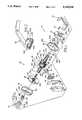
- FIG. 1is an exploded perspective view of a cylindrical lockset embodying certain principles of the invention
- FIG. 2is a plan view of the cylindrical lockset of FIG. 1 in assembly with a door;
- FIG. 3is an exploded perspective view of various components of the cylindrical lockset of FIG. 1 including a latchbolt and retractor, a chassis with rollback sleeves and a force-developing structure all embodying certain principles of the invention;
- FIGS. 4, 5 and 6are partial front views showing various positions of elements of the force-developing structure of FIG. 3;
- FIG. 7is a perspective view of a lever with portions broken away to show structure internally of the lever.
- a cylindrical lockset 20includes an inside subassembly 22 and an outside subassembly 24.
- the inside subassembly 22includes a liner 26, a rose 28, a lever 30, a turnbutton 32 and a lever insert 34.
- the outside subassembly 24includes a liner 36, a rose 38, a lever 40, a cylinder lock 42 and a lever insert 44.
- Cylindrical lockset 20further includes a latchbolt 46 mounted within a casing 48 which is staked or attached to a face plate 50.
- An auxiliary casing 52is provided for larger mounting holes.
- a strike 54 and strike box 56are also illustrated.
- a chassis assembly 58also forms a portion of cylindrical lockset 20 and includes a housing 60, a pair of threaded sleeves 62 and 64 extending from opposite sides of the housing.
- a pair of rollback sleeves 66 and 68extend through sleeves 62 and 64, respectively, and from housing 60.
- a retractor 70is formed with a rear support 72 from which a pair of arms 74 and 76 extend. Arms 74 and 76 are formed at the free ends thereof with inwardly facing lips 78 and 80, respectively, which are separated to provide a space 82 therebetween. Retractor 70 is also formed with a pair of spaced sidewalls 84 and 86 having cam follower surfaces 88 formed thereon. A pair of walls 90 and 92 are located on outer surfaces of arms 74 and 76, respectively, adjacent the free ends thereof.
- a retractor housing 94is formed with lower rails 96 and upper rails 98 having associated rear walls 100 (one shown) all of which are integrally joined by a rear wall 102 of the retractor housing.
- a pair of springs 104 and 106are captured between rear walls 100 of housing 94 and walls 90 and 92, respectively of retractor 70 when the retractor is moved into assembly with the housing.
- arms 74 and 76are located adjacent rails 96 and 98, respectively.
- sidewalls 84 and 86are located outside of the sides of rails 96 and 98.
- a link 108is formed with a head end 110 having a hole 112 formed therethrough and cross arms 114 and 116 at a rear end 118 thereof.
- Head end 110is assembled with latchbolt 46 by use of a pin 120 which extends through hole 112 and a hole (not shown) formed in the latchbolt.
- Cross arms 114 and 116are located between arms 74 and 76, respectively, of retractor 70 and are retained with the retractor by lips 78 and 80, respectively. In this manner, retractor 70 is coupled to latchbolt 46 so that the latchbolt moves upon movement of the retractor.
- Rollback sleeves 66 and 68are each formed with three slots 122, 124 and 126 at the outboard ends of the sleeves. Slots 122 and 126 of each of sleeves 66 and 68 are diametrically opposed to each other while slot 124 is located approximately ninety degrees from slots 122 and 126 at one side of the sleeves.
- the inboard ends of each of sleeves 66 and 68are formed with a pair of rollback cams 128 and 130. Also, a pair of vertically aligned, spaced tabs 132 and 134 are formed on rollback sleeves 66 and 68 at the inboard ends thereof.
- a catch plate 136having a reduced end 138 and a small hole 140 formed therethrough.
- Plate 136is positioned through a slot (not shown) formed in the side of sleeve 66 so that end 138 protrudes slightly out of a T-shaped slot 142 on the other side of the sleeve.
- a pin 144is positioned through the T-shaped slot 142 and the small hole 140 of plate 136 and serves to retain the plate with sleeve 66 in such a manner that end 138 extends in biased fashion through the T-shaped slot. This provides a spring-biased catch for lever 30 to retain the lever on sleeve 66.
- An identical catch arrangementis provided with respect to sleeve 68 by use of catch plate 136 and pin 144.
- a spring plate 146is generally circular in configuration and is formed with a central opening 148 for mounting the plate on sleeve 66.
- a pair of lugs 150 and 152extend in spaced relation from an outboard face 154 of plate 146.
- a hub 156extends from outboard face 154 about opening 148 and has an annular groove 158 formed therein between face 154 and an outboard rim 160 of the hub.
- a pair of diametrically opposed, vertically spaced slots 162 and 164are formed in plate 146 and communicate with opening 148.
- a torsion spring 166is circular in configuration and is formed with two outwardly turned free ends 168 and 170.
- a cap 172is formed by a plate 174 having peripheral edges 175 and radially extending projections 176 spaced about the periphery thereof.
- a pair of spaced tabs 178 and 180are formed in plate 174 adjacent the periphery of the plate and are angled in an inboard direction toward spring plate 146. Threaded sleeve 62 is staked or secured to plate 174 in the arrangement shown in FIG. 3.
- Housing 60is formed by cap 172 and a case 182 which is formed with an opening 184 on one side.
- An annular groove 186is formed within case 182 just inside opening 184 which is interrupted by spaced notches 187 formed in an inboard edge 189 of the case.
- the other side of case 182is formed with a wall 183 having a central opening (not shown) about which threaded sleeve 64 is staked or secured to the wall.
- a pair of tabs 188 and 190are formed in wall 183 in the same manner as tabs 178 and 180 are formed in plate 174.
- a spring plate 192identical in configuration to plate 146, and a torsion spring 194 with ends 196 and 198, which is identical in configuration to spring 166, are arranged for assembly with sleeve 68.
- spring 166is positioned over hub 156 of plate 146 so that ends 168 and 170 are located radially outboard of lugs 150 and 152, respectively, as shown in FIG. 4.
- Cap 172is located adjacent rim 160 of plate 146 with ends 168 and 170 being located radially outboard of tabs 178 and 180 also as shown in FIG. 4.
- spring 166is now captured loosely between plates 146 and 174 and is loosely positioned about but not fully seated in annular groove 158 formed in hub 156.
- hub 156serves to maintain spring 166 in a generally axial arrangement with plate 146 and cap 172.
- spring plate 192, spring 194 and case 182are assembled so that the spring is captured between wall 183 and spring plate 192.
- the assembly of the plate 192, spring 194 and case 182are positioned on rollback sleeve 68 so that tabs 132 and 134 are located in slots 200 and 202, respectively, of the plate.
- peripheral edges 175 of cap 172snap into groove 186 of case 182 so that the cap and case are held together to form housing 60 (FIG. 1). Further, projections 176 of cap 172 fit into notches 187 of case 182 to preclude rotation of the cap relative to the case.
- retractor 70is assembled with housing 94 and springs 104 and 106 as previously described without link 108 being coupled to the retractor.
- retractor 70 and retractor housing 94are also contained within chassis housing 60 formed by cap 172 and case 182.
- Cap 172is formed with a wide notch 204 which aligns with an opening 206 in case 182 when chassis housing 60 is formed and which allows lips 78 and 80, as well as space 82, to appear at opening 206.
- Cross arms 114 and 116can be inserted through notch 204 of cap 172 and into coupling arrangement with retractor 70 as previously described. This is typically accomplished when cylindrical lockset 20 is being assembled with a door 208 as shown in FIG. 2.
- the chassis assembly 58is then positioned as shown in FIG. 1 and assembled with an opening 210 (FIG. 2) of door 208.
- Latchbolt 46 and link 108are then assembled with the chassis assembly 58 as previously described.
- Inside liner 26is then positioned onto sleeve 66 by virtue of a central opening 212 and is placed against the inside surface of door 208.
- a pair of anti-rotation tabs 220 and 222locate in holes (not shown) in door 208.
- two holes 224 formed in liner 26align with two holes (not shown) which have been formed in door 208.
- Inwardly projecting dimples 226are formed in an inboard portion of a rim 228 of liner 26.
- Outside liner 36is formed with a central opening 230 which facilitates positioning of the liner onto sleeve 68.
- a pair of internally threaded posts 232 and 234are staked to and extend from the inboard side of liner 36.
- posts 232 and 234align with the above-noted two holes 224 formed in inside liner 26.
- a pair of screws(not shown) are then placed through the aligned holes 224 and into threaded posts 232 and 234 to draw liners 26 and 36 toward each other with door 208 therebetween. This positions and secures chassis assembly 58 in proper orientation and location with respect to door 208.
- lever 30is formed with a first opening 238 and a second opening 240 which communicates with opening 238.
- a pair of ribs 242 and 244are formed within opening 238.
- an opening 246is formed in an outer face of lever 30 and communicates with opening 238 thereof.
- Turnbutton 32is mounted within an opening 250 at the outboard end of sleeve 66 with the outboard end of the turnbutton projecting outwardly from opening 246 of lever 30 to provide access thereto.
- Turnbutton 32can be used to lock or unlock cylindrical lockset 20 in a conventional manner.
- Cylinder lock 42is formed with a chimney 252 which is inserted into side slot 124 of sleeve 68 when the cylindrical portion of the lock is inserted into the central opening of the sleeve.
- Lever 40is then assembled with sleeve 68 in the same manner as the assembly of lever 30 with sleeve 66.
- slot 249 of lever 40allows chimney 252 to be located in opening 240 of the lever.
- insert 44is positioned within opening 240 and over slot 249 to provide a decorative cover.
- lever 30when lever 30 is in the non-operated or home position, end 168 of spring 166 is located on the outboard sides of lug 150 and tab 178 and end 170 of the spring is located on the outboard sides of lug 152 and tab 180.
- lever 30when lever 30 is operated, that is rotated in a first direction, sleeve 66 is rotated to move cams 128 and 130. Depending on the direction of rotation, one of the cams 128 or 130 will engage an associated one of the cam follower surfaces 88 or retractor 70 to move the retractor further into retractor housing 94 against the biasing action of springs 104 and 106.
- latchbolt 46This structure provides a mechanism the operation of which results in movement of latchbolt 46 from a latched position (FIG. 2) to an unlatched position. In this manner, latchbolt 46 is drawn substantially within case 48 so that no portion of the latchbolt extends beyond the adjacent edge of door 208. It is noted that chassis housing 60 provides an enclosure for the mechanism which moves latchbolt 46.
- the force-developing structureincludes spring plate 146, torsion spring 166 and tabs 178 and 180 of cap 172.
- plate 146is moved to move lugs 150 and 152 therewith. Lug 152 engages end 170 of spring 166 while end 168 of the spring engages fixed tab 178 of cap 172. This action results in tensioning of spring 166 which develops stored energy within the spring. It is noted that the diameter of the convolution of spring 166 is reduced as the spring is tensioned whereby the convolution is allowed to move further into annular groove 158 of hub 156.
- torsion spring 166When lever 30 is released, the stored energy within torsion spring 166 is released to apply a force from end 170 of the spring against lug 152 of plate 146 to move the plate in direction which is the reverse of the direction indicated in FIG. 5. This action causes sleeve 66 to rotate in the reverse direction and to move and return lever 30 to its home position.
- lever 30could be and is operated in a second direction, which is the opposite of the first direction, plate 146 is rotated in the direction shown. In this manner, lugs 150 and 152 are moved whereby lug 150 engages and moves end 168 of spring 166. End 170 of spring 166 engages tab 180 and is precluded from movement with end 168 whereby the spring is tensioned.
- the reverse processoccurs whereby stored energy in tensioned spring 166 develops a force which results in the return of the lever to its home position.
- lever 40and its associated force-developing structure would be accomplished in the same manner as that described above with respect to lever 30.
- lever 30 and lever 40would be operable from its home position in one direction only, that direction usually being a downward direction.
- the force-developing structure associated with lever 30 of a given cylindrical lockset 20would operate only as illustrated in FIG. 5.
- the force-developing structure associated with lever 40 of the same cylindrical lockset 20would operate only in the manner illustrated in FIG. 6.
- spring plate 146Due to the versatility of spring plate 146 being rotatable in either direction, there is no need to relocate the plate and spring 166 when the hand of door 208 is changed, or when the inside-outside orientation of the door is changed.
Landscapes
- Engineering & Computer Science (AREA)
- Mechanical Engineering (AREA)
- Patch Boards (AREA)
Abstract
Description
This invention relates to a cylindrical lockset and particularly relates to a cylindrical lockset having a bias return for a lockset operator, such as a lever, assembled with a chassis of the lockset.
In many locksets, an operator, such as a knob or lever, is attached to components of a chassis to facilitate operation of the lockset and movement of a bolt associated therewith. Typically, a biasing element forms a portion of the lockset and is designed to develop a biasing tension when the operator is moved from a rest or home position so that, upon release of the operator, the operator will be returned to its home position.
Typically, a spring is mounted in a support housing in the form of a cassette and is located outside of the chassis. The spring is coupled through elements of the lockset to the operator and is biased upon operation of the operator to develop the stored return force necessary to return the operator to its home position upon release of the operator.
The spring-containing cassette is typically mounted externally of a housing of the cassette and, therefore, constitutes a separate component of the lockset which must be handled during assembly of the components of the lockset with a door or must be handled and manipulated when, for example, relocating the lockset on the door for the purpose of changing the hand of the door.
Thus, there is a need for a lockset which provides the necessary biasing force to return the operator to its home position but eliminates the need for handling separately any element, which provides such biasing force, during periods of assembly or re-assembly of the lockset with a door.
In view of the foregoing expressed need, it is an object of this invention to provide a cylindrical lockset having an operator-return component which does not require separate handling during assembly or reassembly of the lockset with a door.
Another object of this invention is to provide a cylindrical lockset having an operator-return component which can be assembled at the factory with other components of the lockset and does not require independent handling thereafter for packaging or assembly with a door.
With these and other objects in mind, this invention contemplates a cylindrical lockset mountable on a door which includes a latchbolt and a mechanism, contained within an enclosure, for moving the latchbolt between a latched position and an unlatched position. At least one sleeve extends from one side of the enclosure and is attached to the mechanism for operating the mechanism upon rotation of the sleeve. An operator is mounted on the sleeve for facilitating selective rotation of the sleeve. A force-developing structure is contained within the enclosure and is coupled through the sleeve to the operator. Upon movement of the operator form a non-operated position to an operated position, the structure develops a force which facilitates return of the operator to the non-operated position upon release thereof.
Other objects, features and advantages of the present invention will become more fully apparent from the following detailed description of the preferred embodiment, the appended claims and the accompanying drawings.
In the accompanying drawings:
FIG. 1 is an exploded perspective view of a cylindrical lockset embodying certain principles of the invention;
FIG. 2 is a plan view of the cylindrical lockset of FIG. 1 in assembly with a door;
FIG. 3 is an exploded perspective view of various components of the cylindrical lockset of FIG. 1 including a latchbolt and retractor, a chassis with rollback sleeves and a force-developing structure all embodying certain principles of the invention;
FIGS. 4, 5 and 6 are partial front views showing various positions of elements of the force-developing structure of FIG. 3; and
FIG. 7 is a perspective view of a lever with portions broken away to show structure internally of the lever.
As illustrated in FIG. 1, acylindrical lockset 20 includes aninside subassembly 22 and anoutside subassembly 24. Theinside subassembly 22 includes aliner 26, arose 28, alever 30, aturnbutton 32 and a lever insert 34. Theoutside subassembly 24 includes aliner 36, arose 38, alever 40, acylinder lock 42 and a lever insert 44.
Achassis assembly 58 also forms a portion ofcylindrical lockset 20 and includes ahousing 60, a pair of threadedsleeves sleeves housing 60.
Referring to FIG. 3, aretractor 70 is formed with arear support 72 from which a pair ofarms Arms lips space 82 therebetween.Retractor 70 is also formed with a pair of spacedsidewalls cam follower surfaces 88 formed thereon. A pair ofwalls arms
A retractor housing 94 is formed withlower rails 96 andupper rails 98 having associated rear walls 100 (one shown) all of which are integrally joined by arear wall 102 of the retractor housing. A pair ofsprings rear walls 100 of housing 94 andwalls retractor 70 when the retractor is moved into assembly with the housing. Also, whenretractor 70 is assembled with housing 94,arms adjacent rails sidewalls rails
Alink 108 is formed with ahead end 110 having ahole 112 formed therethrough and crossarms Head end 110 is assembled withlatchbolt 46 by use of apin 120 which extends throughhole 112 and a hole (not shown) formed in the latchbolt.Cross arms arms retractor 70 and are retained with the retractor bylips retractor 70 is coupled tolatchbolt 46 so that the latchbolt moves upon movement of the retractor.
Acatch plate 136 having a reducedend 138 and asmall hole 140 formed therethrough.Plate 136 is positioned through a slot (not shown) formed in the side ofsleeve 66 so thatend 138 protrudes slightly out of a T-shaped slot 142 on the other side of the sleeve. Apin 144 is positioned through the T-shaped slot 142 and thesmall hole 140 ofplate 136 and serves to retain the plate withsleeve 66 in such a manner thatend 138 extends in biased fashion through the T-shaped slot. This provides a spring-biased catch forlever 30 to retain the lever onsleeve 66. An identical catch arrangement is provided with respect tosleeve 68 by use ofcatch plate 136 andpin 144.
Aspring plate 146 is generally circular in configuration and is formed with acentral opening 148 for mounting the plate onsleeve 66. A pair oflugs outboard face 154 ofplate 146. Also, ahub 156 extends fromoutboard face 154 about opening 148 and has anannular groove 158 formed therein betweenface 154 and anoutboard rim 160 of the hub. A pair of diametrically opposed, vertically spacedslots plate 146 and communicate with opening 148.
Atorsion spring 166 is circular in configuration and is formed with two outwardly turnedfree ends
Acap 172 is formed by aplate 174 havingperipheral edges 175 and radially extendingprojections 176 spaced about the periphery thereof. A pair of spacedtabs plate 174 adjacent the periphery of the plate and are angled in an inboard direction towardspring plate 146. Threadedsleeve 62 is staked or secured toplate 174 in the arrangement shown in FIG. 3.
Aspring plate 192, identical in configuration toplate 146, and atorsion spring 194 withends spring 166, are arranged for assembly withsleeve 68.
In assembly ofchassis assembly 58,spring 166 is positioned overhub 156 ofplate 146 so that ends 168 and 170 are located radially outboard oflugs Cap 172 is locatedadjacent rim 160 ofplate 146 withends tabs spring 166 is now captured loosely betweenplates annular groove 158 formed inhub 156. Thus,hub 156 serves to maintainspring 166 in a generally axial arrangement withplate 146 andcap 172.
The assembly ofplate 146,spring 166 andcap 172 are now placed ontosleeve 66 and moved to the inboard end of the sleeve wherebyslots tabs spring plate 146 is coupled torollback sleeve 66 for rotation therewith.
In similar fashion,spring plate 192,spring 194 andcase 182 are assembled so that the spring is captured betweenwall 183 andspring plate 192. The assembly of theplate 192,spring 194 andcase 182 are positioned onrollback sleeve 68 so thattabs slots
Also,peripheral edges 175 ofcap 172 snap intogroove 186 ofcase 182 so that the cap and case are held together to form housing 60 (FIG. 1). Further,projections 176 ofcap 172 fit intonotches 187 ofcase 182 to preclude rotation of the cap relative to the case.
During the assembly process,retractor 70 is assembled with housing 94 and springs 104 and 106 as previously described withoutlink 108 being coupled to the retractor. In this manner,retractor 70 and retractor housing 94 are also contained withinchassis housing 60 formed bycap 172 andcase 182.Cap 172 is formed with awide notch 204 which aligns with anopening 206 incase 182 whenchassis housing 60 is formed and which allowslips space 82, to appear atopening 206.Cross arms notch 204 ofcap 172 and into coupling arrangement withretractor 70 as previously described. This is typically accomplished whencylindrical lockset 20 is being assembled with adoor 208 as shown in FIG. 2.
Thechassis assembly 58 is then positioned as shown in FIG. 1 and assembled with an opening 210 (FIG. 2) ofdoor 208. Latchbolt 46 and link 108 are then assembled with thechassis assembly 58 as previously described. Insideliner 26 is then positioned ontosleeve 66 by virtue of acentral opening 212 and is placed against the inside surface ofdoor 208. In addition, a pair ofanti-rotation tabs door 208. Further, twoholes 224 formed inliner 26 align with two holes (not shown) which have been formed indoor 208. Inwardly projectingdimples 226 are formed in an inboard portion of arim 228 ofliner 26.
Inside rose 28 is placed overliner 26 so that inwardly projectingdimples 236 of the rose snap intodimples 226 of the liner to thereby align and retain the liner with the rose.Rose 38 is assembled ontosleeve 68 and withliner 36 in similar fashion.
As shown in FIG. 7,lever 30 is formed with afirst opening 238 and asecond opening 240 which communicates withopening 238. A pair ofribs opening 238. As shown in FIG. 1, anopening 246 is formed in an outer face oflever 30 and communicates with opening 238 thereof.
After rose 28 has been assembled withliner 26 ondoor 208, the outboard end ofrollback sleeve 66 extends from acentral opening 248 of the rose.Lever 30 is then manipulated to position opening 238 oversleeve 66 so thatribs slots catch plate 136 is biased into a complementary recess (not shown) withinopening 238 oflever 30 to facilitate retention of the lever withsleeve 66.Insert 34 is placed withinopening 240 and aslot 249 oflever 30 to provide a decorative exterior.
Referring to FIG. 4, whenlever 30 is in the non-operated or home position, end 168 ofspring 166 is located on the outboard sides oflug 150 andtab 178 and end 170 of the spring is located on the outboard sides oflug 152 andtab 180. Referring to FIG. 3, whenlever 30 is operated, that is rotated in a first direction,sleeve 66 is rotated to movecams cams retractor 70 to move the retractor further into retractor housing 94 against the biasing action ofsprings latchbolt 46 from a latched position (FIG. 2) to an unlatched position. In this manner, latchbolt 46 is drawn substantially withincase 48 so that no portion of the latchbolt extends beyond the adjacent edge ofdoor 208. It is noted thatchassis housing 60 provides an enclosure for the mechanism which moveslatchbolt 46.
Whenlever 30, which is an operator ofcylindrical lockset 20, is moved in the first direction from its home position, a force-developing structure is operated to develop a force which will facilitate the return of the lever to the home position when the lever is released. Referring to FIGS. 3 and 5, the force-developing structure includesspring plate 146,torsion spring 166 andtabs cap 172. In particular, whensleeve 66 is rotated upon operation oflever 30 in the direction indicated in FIG. 5,plate 146 is moved to movelugs Lug 152 engagesend 170 ofspring 166 whileend 168 of the spring engages fixedtab 178 ofcap 172. This action results in tensioning ofspring 166 which develops stored energy within the spring. It is noted that the diameter of the convolution ofspring 166 is reduced as the spring is tensioned whereby the convolution is allowed to move further intoannular groove 158 ofhub 156.
Whenlever 30 is released, the stored energy withintorsion spring 166 is released to apply a force fromend 170 of the spring againstlug 152 ofplate 146 to move the plate in direction which is the reverse of the direction indicated in FIG. 5. This action causessleeve 66 to rotate in the reverse direction and to move and returnlever 30 to its home position.
Referring to FIG. 6, iflever 30 could be and is operated in a second direction, which is the opposite of the first direction,plate 146 is rotated in the direction shown. In this manner, lugs 150 and 152 are moved wherebylug 150 engages and moves end 168 ofspring 166.End 170 ofspring 166 engagestab 180 and is precluded from movement withend 168 whereby the spring is tensioned. Upon release oflever 30, the reverse process occurs whereby stored energy in tensionedspring 166 develops a force which results in the return of the lever to its home position.
The operation oflever 40 and its associated force-developing structure would be accomplished in the same manner as that described above with respect tolever 30.
It is noted that, typically,lever 30 andlever 40 would be operable from its home position in one direction only, that direction usually being a downward direction. In this instance, the force-developing structure associated withlever 30 of a givencylindrical lockset 20 would operate only as illustrated in FIG. 5. The force-developing structure associated withlever 40 of the samecylindrical lockset 20 would operate only in the manner illustrated in FIG. 6.
Due to the versatility ofspring plate 146 being rotatable in either direction, there is no need to relocate the plate andspring 166 when the hand ofdoor 208 is changed, or when the inside-outside orientation of the door is changed.
In general, the above-described embodiment is not to be construed as limiting the breadth of the present invention. Modifications and other alternative constructions will be apparent which are within the spirit and scope of the invention as defined in the appended claims.
Claims (6)
1. A cylindrical lockset comprising
a latchbolt,
a mechanism for moving the latchbolt between a latched position and an unlatched position,
an axially aligned pair of rotatable sleeves operatively associated with said mechanism,
a housing for said mechanism including
a cylindrical shell having closed opposed ends each having an opening therein for receiving one of said rotatable sleeves,
a pair of coil torsion springs inside said shell, one of said coil torsion springs received by each of said rotatable sleeves, and said received coil torsion springs located adjacent said closed ends,
a pair of ring shaped plates inside said shell, one of said ring shaped plates received by each of said rotatable sleeves, said received ring shaped plates located adjacent said coil torsion springs so that each coil torsion spring is captured between one of said closed ends and one of said ring shaped plates,
each rotatable sleeve and said ring shaped plate received thereon including cooperating key and keyway means for establishing a rotational connection therebetween so that rotation of said rotatable sleeve will rotate said rotationally connected ring shaped plate, and
each ring shaped plate and adjacent closed end including cooperating tab means for subjecting said coil torsion springs to an increasing stress as said ring shaped plates are rotated.
2. A cylindrical lockset according to claim 1, wherein each of said ring shaped plates further comprises a ring shaped hub around which one of said coil torsion springs is located.
3. A cylindrical lockset according to claim 2, wherein an annular groove is defined in said hubs.
4. A cylindrical lockset according to claim 1, wherein one of said shell ends comprises a cap and said cylindrical shell includes an inner annular groove at one end for receiving said cap.
5. A cylindrical lockset according to claim 1, wherein said cooperating tab means comprising
first tab means on each of said ring shaped plates extending axially towards said adjacent closed end, and
second tab means on each of said closed ends extending axially towards said adjacent ring shaped plate,
said first and second tab means being selectively radially located so as to be radially adjacent when said operator is at said latched position, and
said coil torsion springs including radially extending ends engaging either side of said radially adjacent tab means at said latched position.
6. A cylindrical lockset, which comprises:
a latchbolt;
a shell-like case having an open interior and an open side;
a groove formed within the open interior of the case adjacent the open side thereof;
a cap formed with at least one projection along the periphery thereof and insertible into the groove of the case upon assembly of the cap with the case to retain the cap with the case and to form an enclosure;
a mechanism contained within the enclosure for moving the latchbolt between a latched position and an unlatched position;
at least one sleeve extending from one side of the enclosure and attached to the mechanism for operating the mechanism; and
an operator mounted on the sleeve for facilitating selective rotation of the sleeve.
Priority Applications (1)
| Application Number | Priority Date | Filing Date | Title |
|---|---|---|---|
| US07/962,538US5335948A (en) | 1992-10-16 | 1992-10-16 | Cylindrical lockset |
Applications Claiming Priority (1)
| Application Number | Priority Date | Filing Date | Title |
|---|---|---|---|
| US07/962,538US5335948A (en) | 1992-10-16 | 1992-10-16 | Cylindrical lockset |
Publications (1)
| Publication Number | Publication Date |
|---|---|
| US5335948Atrue US5335948A (en) | 1994-08-09 |
Family
ID=25506036
Family Applications (1)
| Application Number | Title | Priority Date | Filing Date |
|---|---|---|---|
| US07/962,538Expired - LifetimeUS5335948A (en) | 1992-10-16 | 1992-10-16 | Cylindrical lockset |
Country Status (1)
| Country | Link |
|---|---|
| US (1) | US5335948A (en) |
Cited By (27)
| Publication number | Priority date | Publication date | Assignee | Title |
|---|---|---|---|---|
| US5460417A (en)* | 1994-08-03 | 1995-10-24 | Emhart Inc. | Tubular lock assembly |
| US5482335A (en)* | 1994-08-03 | 1996-01-09 | Emhart Inc. | Tubular lock assembly |
| US5529354A (en)* | 1994-07-08 | 1996-06-25 | Wright Products Corp. | Spring pack assembly |
| US5666833A (en)* | 1994-09-27 | 1997-09-16 | Tong-Lung Metal Industry Co., Ltd. | Reinforcing apparatus for a lever handle of a door lock |
| WO1997045613A1 (en)* | 1996-05-29 | 1997-12-04 | Geoffrey James Fortune | Latch drive assembly |
| US5735556A (en)* | 1996-12-17 | 1998-04-07 | Kolik Enterprise Co., Ltd. | Cylindrical lockset with reinforced chassis assembly |
| US5820178A (en)* | 1996-07-19 | 1998-10-13 | Baldwin Hardware Corporation | Spring retainer for lock mechanism |
| US5920215A (en)* | 1997-06-30 | 1999-07-06 | Sun Microsystems, Inc. | Time-to-charge converter circuit |
| US6131970A (en)* | 1997-09-25 | 2000-10-17 | Yale Security Inc. | Latch assembly with keyed rose plate for adjustment to doors of differing thickness |
| US20020117868A1 (en)* | 2001-02-23 | 2002-08-29 | Bates Peter K. | Convertible door lock latch mechanism |
| US6540274B2 (en)* | 2001-02-23 | 2003-04-01 | Schlage Lock Company | Slide |
| US6568727B2 (en) | 2001-02-05 | 2003-05-27 | Newfrey Llc | Retention and reinforcement system for knobs and levers |
| US6698803B2 (en) | 2001-01-12 | 2004-03-02 | Schlage Lock Company | Door latching mechanism |
| US6921116B2 (en)* | 2003-01-14 | 2005-07-26 | Hoppe North America, Inc. | Door handle assembly |
| US20070182169A1 (en)* | 2006-01-16 | 2007-08-09 | Jeff Fang | Cylinder lock having improved torsional strength |
| US20080168809A1 (en)* | 2007-01-12 | 2008-07-17 | Cheng-Chung Liu | Cylinder lock with reinforcements to improve structural strength |
| US8844330B2 (en) | 2012-03-14 | 2014-09-30 | Townsteel Inc. | Cylindrical lockset |
| US9181730B1 (en)* | 2014-12-18 | 2015-11-10 | Fu-Chang Peng | Driving structure of electronic lock |
| US9394722B2 (en) | 2013-01-15 | 2016-07-19 | Townsteel, Inc. | Attack-thwarting cylindrical lockset |
| US9528300B2 (en) | 2012-03-14 | 2016-12-27 | Townsteel, Inc. | Cylindrical lockset |
| US20170275917A1 (en)* | 2016-03-23 | 2017-09-28 | Schlage Lock Company Llc | Door lock chassis assembly |
| WO2017205871A1 (en)* | 2016-05-27 | 2017-11-30 | Schlage Lock Company Llc | Status-indicating cylindrical lock assembly |
| US20180298635A1 (en)* | 2017-04-18 | 2018-10-18 | Taiwan Fu Hsing Industrial Co., Ltd. | Rebound apparatus for a lock assembly |
| US20180363329A1 (en)* | 2017-06-19 | 2018-12-20 | Cmech (Guangzhou) Ltd. | Push-pull passage lock mounting device adapted to doors in various sizes |
| US11131118B2 (en)* | 2015-09-02 | 2021-09-28 | Tnbt Holdings Pty Ltd | Latchbolt retractor, a latchbolt assembly, and an assembly for a lockset |
| US20220403920A1 (en)* | 2021-06-18 | 2022-12-22 | Schlage Lock Company Llc | Rotation converter |
| US11725416B2 (en)* | 2016-12-29 | 2023-08-15 | Spectrum Brands, Inc. | Door handle adapter for sprung hub |
Citations (10)
| Publication number | Priority date | Publication date | Assignee | Title |
|---|---|---|---|---|
| US1653512A (en)* | 1923-08-02 | 1927-12-20 | Schlage Lock Co | Door fastener |
| US2470770A (en)* | 1945-01-24 | 1949-05-24 | Independent Lock Co | Communicating door lock |
| US2470771A (en)* | 1945-01-24 | 1949-05-24 | Independent Lock Co | Latch |
| US3954292A (en)* | 1975-06-04 | 1976-05-04 | Amerock Corporation | Door latch with turnable lock button |
| US4042268A (en)* | 1975-04-30 | 1977-08-16 | George Albert Carl Coglan | Latch or lock set and method of manufacture thereof |
| US4123097A (en)* | 1977-05-31 | 1978-10-31 | Norris Industries, Inc. | Sectional entrance handle retract mechanism |
| US4202575A (en)* | 1976-10-22 | 1980-05-13 | G. & S. Allgood (Holdings) Limited | Door handle mechanisms |
| US4453753A (en)* | 1982-06-04 | 1984-06-12 | Baldwin Hardware Manufacturing Corporation | Heat responsive door latch handle |
| US4569547A (en)* | 1984-02-27 | 1986-02-11 | Baldwin Hardware Corporation | Door handle mount |
| US5123682A (en)* | 1990-10-12 | 1992-06-23 | Emhart Inc. | Cylindrical lock assembly |
- 1992
- 1992-10-16USUS07/962,538patent/US5335948A/ennot_activeExpired - Lifetime
Patent Citations (10)
| Publication number | Priority date | Publication date | Assignee | Title |
|---|---|---|---|---|
| US1653512A (en)* | 1923-08-02 | 1927-12-20 | Schlage Lock Co | Door fastener |
| US2470770A (en)* | 1945-01-24 | 1949-05-24 | Independent Lock Co | Communicating door lock |
| US2470771A (en)* | 1945-01-24 | 1949-05-24 | Independent Lock Co | Latch |
| US4042268A (en)* | 1975-04-30 | 1977-08-16 | George Albert Carl Coglan | Latch or lock set and method of manufacture thereof |
| US3954292A (en)* | 1975-06-04 | 1976-05-04 | Amerock Corporation | Door latch with turnable lock button |
| US4202575A (en)* | 1976-10-22 | 1980-05-13 | G. & S. Allgood (Holdings) Limited | Door handle mechanisms |
| US4123097A (en)* | 1977-05-31 | 1978-10-31 | Norris Industries, Inc. | Sectional entrance handle retract mechanism |
| US4453753A (en)* | 1982-06-04 | 1984-06-12 | Baldwin Hardware Manufacturing Corporation | Heat responsive door latch handle |
| US4569547A (en)* | 1984-02-27 | 1986-02-11 | Baldwin Hardware Corporation | Door handle mount |
| US5123682A (en)* | 1990-10-12 | 1992-06-23 | Emhart Inc. | Cylindrical lock assembly |
Cited By (39)
| Publication number | Priority date | Publication date | Assignee | Title |
|---|---|---|---|---|
| US5529354A (en)* | 1994-07-08 | 1996-06-25 | Wright Products Corp. | Spring pack assembly |
| US5460417A (en)* | 1994-08-03 | 1995-10-24 | Emhart Inc. | Tubular lock assembly |
| US5482335A (en)* | 1994-08-03 | 1996-01-09 | Emhart Inc. | Tubular lock assembly |
| US5666833A (en)* | 1994-09-27 | 1997-09-16 | Tong-Lung Metal Industry Co., Ltd. | Reinforcing apparatus for a lever handle of a door lock |
| WO1997045613A1 (en)* | 1996-05-29 | 1997-12-04 | Geoffrey James Fortune | Latch drive assembly |
| US5820178A (en)* | 1996-07-19 | 1998-10-13 | Baldwin Hardware Corporation | Spring retainer for lock mechanism |
| US5735556A (en)* | 1996-12-17 | 1998-04-07 | Kolik Enterprise Co., Ltd. | Cylindrical lockset with reinforced chassis assembly |
| US5920215A (en)* | 1997-06-30 | 1999-07-06 | Sun Microsystems, Inc. | Time-to-charge converter circuit |
| US6131970A (en)* | 1997-09-25 | 2000-10-17 | Yale Security Inc. | Latch assembly with keyed rose plate for adjustment to doors of differing thickness |
| US6698803B2 (en) | 2001-01-12 | 2004-03-02 | Schlage Lock Company | Door latching mechanism |
| US6568727B2 (en) | 2001-02-05 | 2003-05-27 | Newfrey Llc | Retention and reinforcement system for knobs and levers |
| US20020117868A1 (en)* | 2001-02-23 | 2002-08-29 | Bates Peter K. | Convertible door lock latch mechanism |
| US6540274B2 (en)* | 2001-02-23 | 2003-04-01 | Schlage Lock Company | Slide |
| US6802546B2 (en) | 2001-02-23 | 2004-10-12 | Schlage Lock Company | Convertible door lock latch mechanism |
| US6921116B2 (en)* | 2003-01-14 | 2005-07-26 | Hoppe North America, Inc. | Door handle assembly |
| US20070182169A1 (en)* | 2006-01-16 | 2007-08-09 | Jeff Fang | Cylinder lock having improved torsional strength |
| US7748758B2 (en) | 2006-01-16 | 2010-07-06 | Tong-Lung Metal Industry Co., Ltd. | Cylinder lock having improved torsional strength |
| US8182005B2 (en) | 2007-01-12 | 2012-05-22 | Tong Lung Metal Industry Co., Ltd. | Cylinder lock with reinforcements to improve structural strength |
| US20080168809A1 (en)* | 2007-01-12 | 2008-07-17 | Cheng-Chung Liu | Cylinder lock with reinforcements to improve structural strength |
| US8844330B2 (en) | 2012-03-14 | 2014-09-30 | Townsteel Inc. | Cylindrical lockset |
| US9528300B2 (en) | 2012-03-14 | 2016-12-27 | Townsteel, Inc. | Cylindrical lockset |
| US9394722B2 (en) | 2013-01-15 | 2016-07-19 | Townsteel, Inc. | Attack-thwarting cylindrical lockset |
| US9181730B1 (en)* | 2014-12-18 | 2015-11-10 | Fu-Chang Peng | Driving structure of electronic lock |
| AU2016314777B2 (en)* | 2015-09-02 | 2022-03-10 | Tnbt Holdings Pty Ltd | A latchbolt retractor, a latchbolt assembly, and an assembly for a lockset |
| US11131118B2 (en)* | 2015-09-02 | 2021-09-28 | Tnbt Holdings Pty Ltd | Latchbolt retractor, a latchbolt assembly, and an assembly for a lockset |
| US10508468B2 (en)* | 2016-03-23 | 2019-12-17 | Schlage Lock Company Llc | Door lock chassis assembly |
| US20170275917A1 (en)* | 2016-03-23 | 2017-09-28 | Schlage Lock Company Llc | Door lock chassis assembly |
| US11236524B2 (en)* | 2016-03-23 | 2022-02-01 | Schlage Lock Company Llc | Door lock chassis assembly |
| US10301843B2 (en) | 2016-05-27 | 2019-05-28 | Schlage Lock Company Llc | Status-indicating cylindrical lock assembly |
| US11965356B2 (en) | 2016-05-27 | 2024-04-23 | Schlage Lock Company Llc | Status-indicating cylindrical lock assembly |
| US11306506B2 (en) | 2016-05-27 | 2022-04-19 | Schlage Lock Company Llc | Status-indicating cylindrical lock assembly |
| WO2017205871A1 (en)* | 2016-05-27 | 2017-11-30 | Schlage Lock Company Llc | Status-indicating cylindrical lock assembly |
| US11725416B2 (en)* | 2016-12-29 | 2023-08-15 | Spectrum Brands, Inc. | Door handle adapter for sprung hub |
| US12234666B2 (en) | 2016-12-29 | 2025-02-25 | Assa Abloy Americas Residential Inc. | Door handle adapter for sprung hub |
| US20180298635A1 (en)* | 2017-04-18 | 2018-10-18 | Taiwan Fu Hsing Industrial Co., Ltd. | Rebound apparatus for a lock assembly |
| US10844633B2 (en)* | 2017-06-19 | 2020-11-24 | Cmech (Guangzhou) Ltd. | Push-pull passage lock mounting device adapted to doors in various sizes |
| US20180363329A1 (en)* | 2017-06-19 | 2018-12-20 | Cmech (Guangzhou) Ltd. | Push-pull passage lock mounting device adapted to doors in various sizes |
| US20220403920A1 (en)* | 2021-06-18 | 2022-12-22 | Schlage Lock Company Llc | Rotation converter |
| US12006734B2 (en)* | 2021-06-18 | 2024-06-11 | Schlage Lock Company Llc | Rotation converter |
Similar Documents
| Publication | Publication Date | Title |
|---|---|---|
| US5335948A (en) | Cylindrical lockset | |
| US5322333A (en) | Cylindrical lockset | |
| US5125696A (en) | Cylindrical lock assembly | |
| US6279360B1 (en) | Cylindrical lock with simpler positioning assembly | |
| US4228669A (en) | Double cylinder lock with key retention | |
| US7178373B2 (en) | Mortise lock | |
| US6223567B1 (en) | Door lock with clutch arrangement | |
| US5141269A (en) | Cylindrical lock assembly | |
| US5398531A (en) | Rotational housing assembly for a lock assembly with a removable core | |
| CA2103926C (en) | Lever operated door lock assembly | |
| US5651280A (en) | Door lock | |
| US5529354A (en) | Spring pack assembly | |
| US5335950A (en) | Door lockset with spindle bearing | |
| US5123682A (en) | Cylindrical lock assembly | |
| US4938039A (en) | Actuating mechanism for padlock | |
| JPH06180078A (en) | Cylinder lock | |
| US5901590A (en) | Interior door lock assembly with a safety device | |
| KR20020000646A (en) | door locking device | |
| US5269162A (en) | Cylinder lock | |
| US6616203B1 (en) | Door latch operator mount | |
| JPS62228575A (en) | Lock device | |
| JP2601215B2 (en) | Opening and closing mechanism | |
| GB2092658A (en) | Lockable handle assembly | |
| IL99662A (en) | Cylinder lock | |
| US5145223A (en) | Cylindrical lock assembly |
Legal Events
| Date | Code | Title | Description |
|---|---|---|---|
| AS | Assignment | Owner name:EMHART INC., DELAWARE Free format text:ASSIGNMENT OF ASSIGNORS INTEREST.;ASSIGNORS:NORTON, GEORGE H., II;LENK, DAMON J.;ROBIDA, JAMES E.;REEL/FRAME:006355/0864 Effective date:19921014 | |
| AS | Assignment | Owner name:CORBIN RUSSWIN, INC., CONNECTICUT Free format text:ASSIGNMENT OF ASSIGNORS INTEREST;ASSIGNOR:EMHART INC.;REEL/FRAME:006952/0169 Effective date:19940228 | |
| AS | Assignment | Owner name:CORBIN RUSSWIN, INC., CONNECTICUT Free format text:ASSIGNMENT OF ASSIGNORS INTEREST;ASSIGNOR:EMHART INC.;REEL/FRAME:006970/0759 Effective date:19940228 | |
| STCF | Information on status: patent grant | Free format text:PATENTED CASE | |
| FPAY | Fee payment | Year of fee payment:4 | |
| FPAY | Fee payment | Year of fee payment:8 | |
| FPAY | Fee payment | Year of fee payment:12 |