US5335663A - Laparoscopic probes and probe sheaths useful in ultrasonic imaging applications - Google Patents
Laparoscopic probes and probe sheaths useful in ultrasonic imaging applicationsDownload PDFInfo
- Publication number
- US5335663A US5335663AUS07/989,515US98951592AUS5335663AUS 5335663 AUS5335663 AUS 5335663AUS 98951592 AUS98951592 AUS 98951592AUS 5335663 AUS5335663 AUS 5335663A
- Authority
- US
- United States
- Prior art keywords
- array portion
- array
- probe
- carrier
- cross
- Prior art date
- Legal status (The legal status is an assumption and is not a legal conclusion. Google has not performed a legal analysis and makes no representation as to the accuracy of the status listed.)
- Expired - Lifetime
Links
- 238000003384imaging methodMethods0.000titleclaimsabstractdescription59
- 239000000523sampleSubstances0.000titleabstractdescription215
- 238000005520cutting processMethods0.000claimsdescription14
- 238000001574biopsyMethods0.000claimsdescription9
- 230000001154acute effectEffects0.000claimsdescription7
- 238000004519manufacturing processMethods0.000claimsdescription6
- 238000003780insertionMethods0.000claimsdescription5
- 230000037431insertionEffects0.000claimsdescription5
- 230000002093peripheral effectEffects0.000claims1
- 238000002604ultrasonographyMethods0.000abstractdescription18
- 239000012528membraneSubstances0.000abstractdescription12
- 238000002357laparoscopic surgeryMethods0.000abstractdescription9
- 230000005540biological transmissionEffects0.000abstract1
- 239000012530fluidSubstances0.000description24
- 239000000463materialSubstances0.000description12
- 238000007789sealingMethods0.000description11
- 238000000034methodMethods0.000description10
- QSHDDOUJBYECFT-UHFFFAOYSA-NmercuryChemical compound[Hg]QSHDDOUJBYECFT-UHFFFAOYSA-N0.000description8
- 229910052753mercuryInorganic materials0.000description8
- 210000000056organAnatomy0.000description8
- 238000013519translationMethods0.000description5
- 230000014616translationEffects0.000description5
- 229920000126latexPolymers0.000description4
- 230000003340mental effectEffects0.000description4
- 238000012285ultrasound imagingMethods0.000description4
- 230000008878couplingEffects0.000description3
- 238000010168coupling processMethods0.000description3
- 238000005859coupling reactionMethods0.000description3
- 239000011796hollow space materialSubstances0.000description3
- 210000004185liverAnatomy0.000description3
- 238000012986modificationMethods0.000description3
- 230000004048modificationEffects0.000description3
- 229920000515polycarbonatePolymers0.000description3
- 239000004417polycarbonateSubstances0.000description3
- 230000000069prophylactic effectEffects0.000description3
- -1steelChemical class0.000description3
- XLYOFNOQVPJJNP-UHFFFAOYSA-NwaterSubstancesOXLYOFNOQVPJJNP-UHFFFAOYSA-N0.000description3
- 239000004698PolyethyleneSubstances0.000description2
- 210000003815abdominal wallAnatomy0.000description2
- 238000000605extractionMethods0.000description2
- 238000002347injectionMethods0.000description2
- 239000007924injectionSubstances0.000description2
- 229910052751metalInorganic materials0.000description2
- 239000002184metalSubstances0.000description2
- 239000000203mixtureSubstances0.000description2
- 230000003287optical effectEffects0.000description2
- 229920000573polyethylenePolymers0.000description2
- 230000001954sterilising effectEffects0.000description2
- 238000004659sterilization and disinfectionMethods0.000description2
- 210000001835visceraAnatomy0.000description2
- 229920002385Sodium hyaluronatePolymers0.000description1
- 229910000831SteelInorganic materials0.000description1
- 210000000683abdominal cavityAnatomy0.000description1
- 210000003484anatomyAnatomy0.000description1
- 238000013459approachMethods0.000description1
- 238000003491arrayMethods0.000description1
- 239000011248coating agentSubstances0.000description1
- 238000000576coating methodMethods0.000description1
- 238000004891communicationMethods0.000description1
- 239000002131composite materialSubstances0.000description1
- 239000000356contaminantSubstances0.000description1
- 210000001096cystic ductAnatomy0.000description1
- 230000003247decreasing effectEffects0.000description1
- 230000007812deficiencyEffects0.000description1
- 238000013461designMethods0.000description1
- 230000005611electricityEffects0.000description1
- 210000003754fetusAnatomy0.000description1
- 210000000232gallbladderAnatomy0.000description1
- 230000005484gravityEffects0.000description1
- 208000015181infectious diseaseDiseases0.000description1
- 230000002401inhibitory effectEffects0.000description1
- 239000007788liquidSubstances0.000description1
- 230000007257malfunctionEffects0.000description1
- 150000002739metalsChemical class0.000description1
- 230000005693optoelectronicsEffects0.000description1
- 229920000915polyvinyl chloridePolymers0.000description1
- 239000004800polyvinyl chlorideSubstances0.000description1
- 230000035935pregnancyEffects0.000description1
- 238000002360preparation methodMethods0.000description1
- 229940010747sodium hyaluronateDrugs0.000description1
- YWIVKILSMZOHHF-QJZPQSOGSA-Nsodium;(2s,3s,4s,5r,6r)-6-[(2s,3r,4r,5s,6r)-3-acetamido-2-[(2s,3s,4r,5r,6r)-6-[(2r,3r,4r,5s,6r)-3-acetamido-2,5-dihydroxy-6-(hydroxymethyl)oxan-4-yl]oxy-2-carboxy-4,5-dihydroxyoxan-3-yl]oxy-5-hydroxy-6-(hydroxymethyl)oxan-4-yl]oxy-3,4,5-trihydroxyoxane-2-Chemical compound[Na+].CC(=O)N[C@H]1[C@H](O)O[C@H](CO)[C@@H](O)[C@@H]1O[C@H]1[C@H](O)[C@@H](O)[C@H](O[C@H]2[C@@H]([C@@H](O[C@H]3[C@@H]([C@@H](O)[C@H](O)[C@H](O3)C(O)=O)O)[C@H](O)[C@@H](CO)O2)NC(C)=O)[C@@H](C(O)=O)O1YWIVKILSMZOHHF-QJZPQSOGSA-N0.000description1
- 239000007787solidSubstances0.000description1
- 239000010959steelSubstances0.000description1
- 239000000126substanceSubstances0.000description1
- 238000001356surgical procedureMethods0.000description1
Images


Classifications
- A—HUMAN NECESSITIES
- A61—MEDICAL OR VETERINARY SCIENCE; HYGIENE
- A61B—DIAGNOSIS; SURGERY; IDENTIFICATION
- A61B8/00—Diagnosis using ultrasonic, sonic or infrasonic waves
- A61B8/12—Diagnosis using ultrasonic, sonic or infrasonic waves in body cavities or body tracts, e.g. by using catheters
- A—HUMAN NECESSITIES
- A61—MEDICAL OR VETERINARY SCIENCE; HYGIENE
- A61B—DIAGNOSIS; SURGERY; IDENTIFICATION
- A61B8/00—Diagnosis using ultrasonic, sonic or infrasonic waves
- A61B8/44—Constructional features of the ultrasonic, sonic or infrasonic diagnostic device
- A61B8/4444—Constructional features of the ultrasonic, sonic or infrasonic diagnostic device related to the probe
- A61B8/445—Details of catheter construction
- A—HUMAN NECESSITIES
- A61—MEDICAL OR VETERINARY SCIENCE; HYGIENE
- A61B—DIAGNOSIS; SURGERY; IDENTIFICATION
- A61B8/00—Diagnosis using ultrasonic, sonic or infrasonic waves
- A61B8/44—Constructional features of the ultrasonic, sonic or infrasonic diagnostic device
- A61B8/4483—Constructional features of the ultrasonic, sonic or infrasonic diagnostic device characterised by features of the ultrasound transducer
- A61B8/4488—Constructional features of the ultrasonic, sonic or infrasonic diagnostic device characterised by features of the ultrasound transducer the transducer being a phased array
Definitions
- the present inventionrelates to ultrasonic imaging apparatus that are particularly suited for use in laparoscopic surgery.
- Ultrasonic imaginghas found several applications in the medical field, especially to view internal anatomical tissue and structures.
- One well known applicationfor example, is to use a hand held ultrasonic probe to image a developing fetus during pregnancy.
- Ultrasonic imaginghas also found application in laparoscopic surgery, such as in the performance of biopsies and excision of internal organs or other tissue.
- Laparoscopic surgeryinvolves the use of small diameter tools that are inserted into a patient's body cavity through a small hole in the abdominal wall.
- the holeis made by puncturing the abdominal wall with a sharp edged instrument called a trocar.
- a small working tube, called a cannulais then inserted into the hole to hold it open.
- the trocar and cannulaare configured in a single structure.
- the cannulais usually fitted inside with some type of sealing apparatus, such as, for example, a flapper valve that can be forced open by a tool entering through the cannula, and which springs closed to seal the internal passageway through the cannula when not in use.
- the cannulacan also be fitted with annular sealing devices for sealing between a probe inserted through the cannula and the inside wall of the cannula.
- annular sealing devicesfor sealing between a probe inserted through the cannula and the inside wall of the cannula.
- Various probeshave been used to aid laparoscopic surgical operations. For example, optical probes are often used to view the outer surfaces of internal organs. Also, ultrasonic probes have been used to assist in viewing the internal structures of organs to obtain information that may be necessary for performance of certain surgical operations. For example, a surgeon might need to be able to identify and distinguish the cystic duct from the common duct in the gall bladder/liver to perform certain procedures.
- a variety of ultrasonic probeshave been used in laparoscopic procedures.
- One type of probehas a single transducer that is mechanically moved through an arc to transmit or receive ultrasonic signals over a pie-shaped area. Such a mechanical sector scanner can be positioned on a probe to image in either a forward or a side direction.
- a second type of ultrasonic probe that is used to transmit or receive ultrasonic signals over an areacontains several transducer elements arranged in an array.
- One type of array probe that has been usedcontains several transducers arranged in a line along the side of a cylindrically shaped probe. Such a linear array provides side imaging capability.
- Another type of array probealigns the array of transducer elements along a curve at or near the end of a probe to provide forward looking capability.
- Such a curved arraytransmits and receives ultrasonic signals over a pie-shaped area like the mechanical sector scanner.
- curved arraysare not well suited for imaging near the probe, as is often desirable during surgery, because of a limited field of imaging in the region near the curved array.
- forward imagingcan be used to determine when a probe is at the location into the body cavity for side imaging organs or other tissue of interest which cannot be adequately viewed with a forward imaging probe.
- a forward imaging probemight first be inserted so that a surgeon can determine the proper distance into the body cavity at which the operation is generally to be performed and possibly also to locate an organ or other tissue of interest. The forward imaging probe is then removed and a side imaging probe is inserted to obtain a better view of the organ or other tissue of interest in preparation for a medical operation that is to be performed on the tissue, such as excising tissue or taking a biopsy sample.
- the use of two probesis awkward. It is difficult for a surgeon performing a complex operation to mentally reorient between the forward and side looking images. Also, assuring proper repositioning of the probe at the proper distance into the body cavity can present a problem.
- ultrasonic images produced by ultrasonic medical probesare displayed on a video monitor with a fixed frame of reference.
- the imageis typically displayed on the monitor from top to bottom, with the distance away from the ultrasonic probe increasing going down the screen. Therefore, tissue nearest the ultrasonic probe is displayed at the top of the monitor and tissue farthest from the probe appears at the bottom of the monitor.
- a surgeon, or other medical professional, viewing the ultrasound imagemust mentally translate the image as displayed on the monitor to a frame of reference in the patient's body, thereby orienting the image in order to properly locate organs or other tissue of interest. Also, when the probe is moved from one position to another, or rotated to image in a different plane, the surgeon must also mentally reorient that new image relative to the old image. For example, if the surgeon is viewing a first ultrasonic image with the probe in a first position looking sideways and then rotates the probe counterclockwise to produce a second image, the surgeon must mentally translate the second image counterclockwise from the first image to properly conceptualize the patient's anatomy.
- one method for locating, identifying, and cutting tissueinvolves inserting an ultrasonic probe into the patient's body cavity to locate and identify the tissue to be cut and internal structures to be avoided. The ultrasonic probe is then removed and a surgical instrument is inserted and positioned to perform the cutting based on the information obtained from the ultrasonic probe. Positioning the surgical tool to properly perform the desired cut, however, based upon the information provided by the ultrasonic probe may be difficult, and it is possible that an improper cut can be made.
- ultrasonic contactOne problem often encountered with performing ultrasonic scans during laparoscopic operations is establishing good ultrasonic contact between ultrasonic transducers and tissue, the underlying structure of which is to be imaged. Good ultrasonic images can be produced only if adequate ultrasonic contract, often referred to as coupling, can be made between the tissue and ultrasonic transducers. Obtaining such ultrasonic contact is often difficult. For example, an ultrasonic device may be on the side of a probe, but only the tip of the probe can be contacted with the tissue of interest. Or, for example, it may be possible to contact the ultrasonic device and the tissue of interest, but in so doing the tissue is physically distorted and, therefore, the ultrasound image produced may be misleading.
- laparoscopic probesare difficult to sterilize.
- One attempt to resolve the sterilization problemhas been to place a sterile disposable cover, or sheath, over the laparoscopic probe prior to insertion of the probe into a body cavity. After removal of the probe, the sheath is discarded. As a consequence, the need for extensive sterilization of the probe is reduced.
- One type of sheath that has been used to cover laparoscopic probesis a loose fitting, thin-walled, highly flexible prophylactic sheath made of an elastomeric-type material, such as latex rubber.
- One problem with the loose fitting prophylactic sheathis that it tends to catch and bind in the seals and/or a flapper valve in the cannula thereby inhibiting insertion and extraction of the probe.
- the prophylactic sheathmay tear, thereby defeating the very purpose of the sheath in providing a sterilized surface.
- sheathAnother type of sheath that has been used is a thin-walled, tightly fitting, highly flexible sheath made of elastomeric-type material, such as latex rubber.
- the sheathis fitted on the probe by first inflating the sheath, like a balloon, and then inserting the probe into the inflated sheath. The sheath is then deflated to tightly fit around the probe. Because of the thin-walled, highly flexible nature of the sheath, however, there is still potential for binding in the cannula. Also, the procedure of fitting the sheath onto a probe is time consuming and awkward in the surgical environment.
- the present inventionprovides an ultrasonic imaging probe having both forward and side imaging capabilities on a single probe.
- the probecomprises a carrier and an array of ultrasonic transducers capable of imaging in a forward direction beyond the end of the end portion of the probe that is inserted into the patient's body.
- the ultrasonic arrayincludes a first array portion that includes at least one ultrasonic transducer oriented to image at an acute angle relative to the longitudinal axis of the carrier such that the transducer images in a forward direction beyond the end of the probe.
- the arrayalso includes a second portion having a plurality of ultrasonic transducers arranged in a substantially linear fashion and substantially parallel to the longitudinal axis of the carrier for side imaging.
- the first array portionincludes a plurality of transducers that are oriented so as to define a substantially planar curve, i.e., a curve that lies substantially in a single plane.
- the planar curvehas a large radius of curvature that extends over an acute included angle, thereby facilitating manufacture of the probe by making electrical connections to individual transducer elements easier to make.
- the planar curvecan have an increasing radius of curvature. By having a large radius of curvature, thereby decreasing the angle in which the curve is included, or by having an increasing radius of curvature, additional room is provided to make electrical connections to individual elements over the length of the curve. This can be particularly advantageous when the radius of the carrier is very small, such as with instruments used in laparoscopic surgery.
- the carrier of the probeis substantially cylindrical over much of its length, with the substantially circular cross section defining the areal boundary, perpendicular to the longitudinal axis, within which all portions of the probe must lie.
- the transducer elements of the second array portionarranged substantially in a line parallel with the longitudinal axis, are recessed relative to the areal boundary, thereby permitting other surgical tools, such as a biopsy needle, to be located within or passed through the recess.
- those other surgical toolscan be positioned within the imaging field of the linear portion of the array, thereby allowing a surgeon to simultaneously obtain an image of both the body tissue of interest and the surgical tool.
- the ultrasonic imaging apparatusincludes an ultrasonic probe with at least one ultrasonic element that transmits a first electrical signal, representative of a received ultrasonic signal, a position sensor that produces a second electrical signal representative of the position of the probe, a processor for constructing a video image of the ultrasonic signal for display on a video monitor from the first electrical signal and manipulating the video image using the second electrical signal to reflect the orientation of the ultrasound image. For example, a first video image could be displayed on a video monitor representing an ultrasound image produced at a first position with a side imaging ultrasound probe.
- both a rotational position sensor and a translational position sensorare provided so that both rotations and translations of images can be effected.
- Yet another embodimentincludes a device for establishing a reference point for the position sensor that relates to a patient's body so that the ultrasound image displayed on a video monitor can be oriented to the patient.
- the position sensorcan produce data that allows a video image to be constructed in which the top of the video monitor corresponds to the patient's head and the bottom of the video monitor corresponds to the patients feet, regardless of the direction in which the ultrasonic probe is imaging.
- the inventionis directed to the problem locating or identifying the tissue of interest and then performing a cutting or other surgical operation.
- the inventionprovides a laparoscopic probe that includes both a surgical device for cutting and/or cauterizing tissue and an ultrasonic device with a field of imaging that either includes the surgical device or is immediately adjacent to the surgical device. Because the surgical device is integral with the probe containing the ultrasonic device and is proximately located to the ultrasonic device, the surgeon is less likely to make improper cuts.
- the surgical deviceincludes an electrocautery hook that is positioned within or adjacent to the ultrasonic field of imaging of an ultrasonic array.
- a surgeoncan locate and identify the proper tissue for cutting as well as the internal structures that are not to be cut. After locating the proper tissue, the surgeon can activate the electrocautery hook and, because of the overlapping or immediately adjacent field of imaging, can closely control the precise position at which the cut is made.
- a further embodiment of the present inventionaddresses the need to establish ultrasonic contact between an ultrasonic device and tissue of interest.
- the apparatuscomprises a carrier, an ultrasonic device mounted on the carrier, and a device for use in injecting an ultrasonically transmissive medium adjacent to the ultrasonic device.
- the transmissive mediumis placed in the vicinity of the ultrasonic device for the purpose of establishing an ultrasonic circuit, or bridge, with the tissue that is located in the field of view of the ultrasonic device.
- a high viscosity fluidis used as the transmissive medium.
- High viscosity fluidshave the advantage that the medium has a reduced tendency, relative to lower viscosity fluids, to disperse or flow away from an area immediately adjacent to the ultrasonic device. Consequently, a relatively small amount of such high viscosity fluid can be used to provide the necessary ultrasonic contact for imaging the tissue of interest.
- the resultis that a relatively small amount of transmissive medium is used which is relatively easy to remove from the body following ultrasonic imaging. Ease of removal is facilitated by the small amount of medium and an increased tendency of high viscosity medium to remain in the vicinity of the ultrasonic device.
- the transmissive mediumadheres to the outer surfaces of the carrier and ultrasonic device and does not disperse or flow away from that immediate vicinity.
- One embodiment of the present inventionprovides a disposable sheath for covering a probe that is to be inserted into a patient's body cavity.
- the sheathis a rigid structure that substantially reduces, or eliminates, any problem with binding of the sheath in the cannula as has been experienced with the thin walled, highly flexible, elastomeric-type sheaths of the prior art.
- the sheathincludes a chamber within the sheath.
- the chambercontains an ultrasonically transmissive medium and is sealed with a breakable membrane.
- the probebreaks the membrane and the ultrasonic device of the probe enters the chamber containing the ultrasonically transmissive medium. An ultrasonic circuit is thereby established between the ultrasonic device and the sheath.
- the sheathincludes an inflatable balloon at or near a first terminal end of the sheath that is inserted into the patient's body cavity.
- the ballooncan be inflated with an ultrasonically transmissive medium to establish an ultrasonic circuit between an ultrasonic device of the probe inserted into the sheath and tissue to be ultrasonically scanned.
- sheathis shaped to establish a desired orientation between the ultrasonic probe and the sheath. Orientation is such that the ultrasonic device of the probe is always adjacent to one or more lumens through which ultrasonically transmissive medium can be transmitted to and injected immediately adjacent the sheath in the direction of the ultrasonic beam. An ultrasonic circuit between the sheath and tissue of interest is established by the excreted medium.
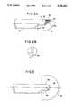
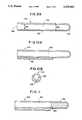
- FIGS. 1A and 1Bshow a side view and a top view of a probe containing a 90° curved first array portion and a linear second array portion of an ultrasonic transducer array, which second array portion is recessed to allow for passage of a surgical tool, such as a biopsy needle;
- FIGS. 2A and 2Bshow a side view and end view of a probe having both a curved first array portion and a linear second array portion of an ultrasonic transducer array, with the curved first array portion included within an acute angle and having an enlarged radius of curvature to facilitate the making of electrical connections to individual transducer elements;
- FIG. 3shows a side view of a probe having an ultrasonic transducer array comprised of a 180° curved first array portion and two linear array portions;
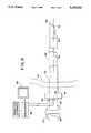
- FIG. 4shows an apparatus for use in performing ultrasonic imaging that includes translational and rotational position sensing devices for sensing the position of an ultrasonic probe and using the position information to manipulate the displayed ultrasonic video image;
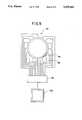
- FIG. 5shows a mercury switch that can be used to sense rotational position of a probe based on gravitational force
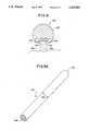
- FIG. 6shows a probe having an ultrasonic transducer array and an electrocautery hook located partially within the field of imaging of the array
- FIG. 7shows a laparoscopic probe having an ultrasonic array and lumens for injecting transmissive fluid in the vicinity of an ultrasonic transducer array
- FIG. 8shows a cross section of a probe having means for injecting transmissive fluid adjacent to an ultrasonic transducer array
- FIGS. 9A and 9Bshow a perspective view and a cross sectional view along the longitudinal axis of a first embodiment of a rigid sheath
- FIGS. 10A and 10Bshow a cross section along the longitudinal axis and a cross section perpendicular to the longitudinal axis of a second embodiment of a rigid sheath that also has a lumen that can be used for various purposes;
- FIG. 11shows another embodiment of the sheath having a chamber filled with transmissive medium and sealed with a breakable membrane
- FIG. 12shows the sheath of FIG. 11 in which the sealing membrane has been broken and a probe has been inserted into the chamber;
- FIG. 13shows another embodiment of the sheath having a balloon on the end that can be inflated with an ultrasonically transmissive medium through a lumen in the sheath;
- FIG. 14shows the sheath of FIG. 13 with the balloon inflated with ultrasonically transmissive medium and in which an ultrasonic probe has been inserted;
- FIG. 15shows a cross section of a sheath having lumens for placing transmissive medium in a area to be ultrasonically imaged.
- the present inventionis an ultrasonic probe that provides ultrasonic imaging both in a forward direction past the end of the probe that is inserted into a patient's body and also to the side of the probe.
- the probeis particularly suited for use in laparoscopic surgical operations.
- FIGS. 1A and 1Bshow one embodiment of a probe.
- Probe 20comprises a carrier having a longitudinal axis 22 extending between a first terminal end 24, which is inserted into the patient's body, and a second terminal end, not shown, which remains outside of the patient's body. Extending through the carrier is a smaller diameter conduit 26, called a lumen, through which surgical tools, such as a biopsy needle 28, can be transmitted from outside of the patient's body to a recess area 30 near the first terminal end 24.
- a carrier for a laparoscopic probewould have a maximum cross sectional width smaller than about 12 millimeters, and often from about 10 millimeters to about 12 millimeters.
- the probe 20also has an array 32 of ultrasonic transducers comprising a curved first portion 34 and a linear second portion 36.
- the curved portion 34has at least one ultrasonic transducer that is situated to image at an acute angle relative to the longitudinal axis 22.
- the curved portion 34comprises a plurality of ultrasonic transducer elements arranged in a planar curve.
- the curved portion 34 shown in FIG. 1Ais configured as a planar curve having a 90° included angle and a radius of curvature 38, as shown.
- the curved portion 34is continuous with the linear portion 36, which has a plurality of ultrasonic transducer elements located substantially in a line that is substantially parallel to the longitudinal axis 22.
- the linear portion 36therefore, produces an ultrasound image directed to the side of the probe.
- An array having a curved first portion extending over a 90° arc and a linear second portion, as shown in FIG. 1A,has an ultrasound imaging pattern 40 extending from a full forward imaging position at one end of the curved portion 34 to a full side imaging position along the linear portion 36.
- the array 32is preferably located relative to the lumen 26 so that a surgical tool, such as a biopsy needle 28, exiting the lumen 26 will pass through the recess area 30 in such a manner that the tool passes through the field of view of the linear portion 36 of the array. If the tool exiting the lumen 26 is extended through the recess beyond the linear portion 36, such tool would also preferably pass within the field of view of the curved portion 34 of the array. This ability to pass surgical tools directly to the vicinity of the array 32 can facilitate precise placement of tools, such as biopsy needles, at the desired point as located by the ultrasonic image produced by the array 32.
- the array 32has at least about thirty-two transducer elements, more preferably at least about sixty-four transducer elements, and most preferably at least about one hundred and twenty-eight transducer elements.
- the relative number of transducer elements included in the curved portion 34 relative to the linear portion 36will depend upon the specific embodiment and the relative needs for viewing beyond the first terminal end of the carrier and viewing to the side of the carrier. Frequently, however, transducer elements will be equally split between the two portions.
- Transducer elementsare typically from about 3 mm to about 5 mm long. The individual transducer elements can be spaced at any convenient distance from each other, providing that spacing is close enough to provide adequate imaging.
- transducer elementsare spaced from about 0.1 mm to about 0.3 mm on center and preferably at about 0.2 mm on center, with the longitudinal axis of the transducer elements extending into the internal space of the carrier.
- An array with one hundred twenty-eight transducerswould, therefore, be approximately one inch long as measured along the surface of the array.
- the side looking second portion 36is particularly suited for viewing a particular organ or other tissue once the probe has been positioned at the proper distance within the patient's body.
- FIGS. 2A and 2Bshow another embodiment of a laparoscopic ultrasonic probe having features as previously described for the probe shown in FIGS. 1A and 1B, except as noted.
- the first portion 42 of the ultrasonic transducer arrayis shown as arranged in a planar curve having a larger radius of curvation than that shown in FIGS. 1A and 1B.
- the curved portion 42has an acute included angle. Therefore, the curved first portion 42 has a capability of imaging, as shown by the imaging pattern 46, beyond the end of the probe that is somewhat restricted relative to the 90° curved first portion 34 shown in FIG. 1A.
- the relatively flatter curve of the curved portion 42 relative to that shown in FIG. 1Ais due to the larger radius of curvature 48 that extends well beyond the edge of the probe carrier, as shown.
- the relatively flatter curve in the arc of curved portion 42although somewhat reducing the forward viewing capability of the array, has the advantage of facilitating electrical connection of transducer wires 50 to individual transducer elements in the curved first array portion 42.
- Such additional space for making electrical connections to individual transducer elementscan significantly decrease the cost of manufacturing the probe.
- an increasing radius of curvaturecan also be used.
- the radius of curvature of the curved array portioncould be smallest at the end of the curved portion nearest the end of the probe and could increase, thereby flattening the curve, moving along the curved portion away from the end of the probe.
- the probe shown in FIGS. 2A and 2Balso has a lumen 52 extending through the carrier and through which surgical tools can be transmitted to a recessed area in the vicinity of the linear second array portion 54.
- FIG. 3shows another embodiment of an ultrasonic probe for use in laparoscopic surgery.
- the first portion 56 of the arrayextends over a full semi-circle.
- Other configurations for the first portion that extend from one side of the probe to the otherare also possible, and need not extend through a full 180°.
- this probecontains two linear portions 58 and 60, thus providing an imaging pattern 61 extending down two sides of the probe and completely around the front of the probe.
- Another aspect of the present inventioninvolves sensing the position of an ultrasonic probe, generating an electrical signal representative of the position of the probe, and using that electrical signal to orient a video display of an ultrasonic image generated by the probe.
- FIG. 4shows one embodiment of the invention.
- An ultrasonic probe 62 with a longitudinal axis 64having a first terminal end 66 that is inserted into a patient's body and a second terminal end 68 that is connected to a handle 70, with which a surgeon would manipulate the probe.
- the first terminal end 66 of the probeis inserted into the patient's body through a hole in the abdominal cavity 72 that is held open by a tubular device 74, called a cannula, the internal passageway through which is often referred to as a surgical port.
- An array 76 having a plurality of ultrasonic transducersis located near the first terminal end 66 of the probe.
- the ultrasonic transducersproduce first electrical signals that are applied to a processor 78 that places the signals in a form suitable for display as a video ultrasound image on a video monitor 80. Electrical circuits for the ultrasound transducers are not shown.
- a first position sensor 84monitors the translational position of the probe 62 along the longitudinal axis 64.
- a second position sensor 86monitors the rotational position of probe 62 about the longitudinal axis 64.
- the first positional sensor 84generates an electrical signal representative of the translational position of the probe which goes to a processor 78 and is used to manipulate ultrasound video images formed from the signals provided by the array 76.
- the electrical signal provided by the first positional sensor 84can be used to generate consecutive video ultrasound images to be displayed sequentially across the video monitor in proper spacial relationship to one another in a translational direction.
- the second position sensor 86generates an electrical signal that is representative of the rotational portion of the probe which is transmitted to a processor 78 where the signal is used to manipulate and orient an ultrasound video image formed from the signals provided by the array 76 relative to the rotational position of the array 76 on the probe 62. For example, if the array 76 is imaging at a first position and is subsequently rotated to a second position in a counterclockwise direction, the ultrasound video image on the monitor 80 also rotates on the video monitor screen in a counterclockwise direction.
- a reference pointcan be set so that a particular direction on the video monitor represents a specific orientation relative to the patient. For example, if a probe is inserted through the surgical port and travels in a vertical direction into the body cavity, it may be desirable to select the top of the video monitor as corresponding to the head of the patient. If the ultrasonic array is then rotated to image in a direction towards the head, the portions of the image closest to the ultrasonic array will appear at the bottom of the video monitor and the portions of the image farthest from the array, being closer to the head, will appear at top of the video monitor.
- the probeis then rotated to image in a direction towards the feet, then those portions of the image closest to the probe will be near the top of the video monitor and those portions of the image farthest from the probe will appear near the bottom of the video monitor. If the probe is positioned to look to one side, or the other, of the patient's body then portions of the image closest to the array would show near the appropriate side of the monitor.
- Positional sensors 84 and 86can be any devices that produce electrical signals indicative of the position of the probe 62.
- these sensorsmight have friction wheels that contact the probe 62 and that are coupled to opto-electronic encoders or counters that produce electrical signals.
- Another method of sensing positionmight be to put a series of dots, lines, or other marks directly on the shaft of the ultrasound probe 62 and to optically detect the motion of these marks using reflective encoders as position sensors 84 and 86.
- rotational position sensor 84which is mounted at the surgical port
- a rotational sensor that is sensitive to gravitational forcecould be placed within the probe.
- a gravitationally sensitive sensor 88would be positioned near the first terminal end in the vicinity of the array 76.
- a gravitationally sensitive sensor 90could be placed in the handle 70 attached to the probe 62.
- One suitable gravitationally sensitive position sensoris a switch having an electrically conductive mass, such as a ball of liquid mercury or a solid metal ball, that is capable of responding to gravitational force to close one of several contacts in the switch.
- FIG. 5shows a switch 92 actuated by a ball of mercury.
- a ball of mercury 94 in mercury switch 92moves such that the mercury is always at the position of the switch pointing in a downward direction in response to the gravitational force.
- the mercury switchwill, therefore, complete the circuit with the contact that is pointing down and an electrical signal will be generated in the circuit completed by the contact and the electrical signal is transmitted to a processor 98 where it is used to orient an ultrasonic video display on video monitor 100. Rotation of the ultrasound video image is as described previously for rotational position sensor 84 as shown in FIG. 4.
- a reference pointcan be established for orientation of a video ultrasound image relative to the patient.
- the reference point for the position sensorscan be established in either an absolute or a relative sense. For example, if a rotational position sensor is used that responds to gravity, then image orientation can be established with respect to actual up/down orientation. If however, the position sensor consists of either an optical or mechanical encoder, then in order to establish a reference position, the system operator would have to move the probe into a predetermined position (i.e., image plane from front to back) and then notify the system by means of a switch or contact closure, via an operator interface 101 with processor 78, that the probe is in the reference position.
- a predetermined positioni.e., image plane from front to back
- the present inventionprovides a probe for internal use in medical operations, and particularly for use with laparoscopic surgery, that includes both a surgical device and an ultrasonic device with a field of imaging that either includes the surgical device or is immediately adjacent to the surgical device.
- the surgical deviceis a tool designed for cutting and/or cauterizing tissue, such as, for example an electrocautery hook, a laser, or an ultrasonic cutter.
- Combining a surgical device in close proximity with an ultrasonic device on a probeis particularly advantageous when the surgical device is designed to cut and/or cauterize tissue, because the combination provides close control of the cutting operation to assure that only the intended tissue is actually cut and/or cauterized.
- FIG. 6shows one embodiment comprising an electrocautery hook.
- the probe 102has a carrier 104 with a longitudinal axis 106 extending between a first terminal end 108 that enters into a patient's body and a second terminal end, not shown, that remains outside of the patient's body.
- Mounted at the first terminal end 108is an electrocautery hook 110 that is connected to electrical wires 112 that supply electricity to the electrocautery hook to provide the required thermal energy for cutting and/or cauterizing tissue.
- Also mounted near the first terminal endis an array 114 having a plurality of ultrasonic transducer elements connected to electrical wires 116 that transmit electrical signals that are representative of an ultrasonic signal received by the array 114 that can be processed and displayed on a video monitor.
- the ultrasonic transducer array 114is mounted on the carrier in such a manner that the field of imaging includes the tip of the electrocautery hook 110. Therefore, a surgeon using such a probe would be able to simultaneously view the tissue to be cut and the tip of the electrocautery probe. The surgeon would, therefore, have a high degree of control in assuring that only the proper tissue is cut.
- the present inventionprovides an apparatus, such as a probe useful in laparoscopic surgery, and a method for establishing an ultrasonic circuit to facilitate ultrasonic imaging of body tissue of interest.
- the apparatuscomprises a carrier, an ultrasonic device mounted on the carrier, and means for injecting an ultrasonically transmissive medium adjacent to the ultrasonic device.
- FIGS. 7 and 8show a probe 120 having an array 122 of ultrasonic transducers and two lumens 124 passing through the carrier 126.
- the lumens 124are used to transmit an ultrasonically transmissive medium 136 to openings 128 adjacent to the array 122 of transducer elements.
- the probe 120In the case of laparoscopic surgical operations, the probe 120 would be inserted into the patient's body and moved to a position as close as possible to tissue 138 of interest for the purpose of obtaining an ultrasonic image of that tissue.
- an ultrasonically transmissive fluidis injected through the lumens 124 such that the ultrasonically transmissive fluid exits from openings 128 adjacent to the transducer array 122. Consequently, the ultrasonically transmissive fluid can establish an ultrasonic circuit between the array 122 and tissue 138 in the field of view of the array.
- the transmissive mediumcan be any substance that is ultrasonically transmissive and capable of being injected through the lumens 124.
- a higher viscosity fluidis used to reduce the tendency of the transmissive medium to disperse or flow away from the immediate vicinity of the transducer array 122.
- a high viscosity fluidthat has a viscosity of greater than about 20,000 cP and preferably from about 20,000 cP to about 80,000 cP.
- One suitable high viscosity fluidinclude, for example, is sodium hyaluronate, having a viscosity of approximately 40,000 cP.
- the high viscosity fluidafter being injected through the openings 128, adheres to the surface of the transducer 122 array and to the carrier 120 in the immediate vicinity, thereby forming an ultrasonically transmissive circuit between the transducer array 122 and the tissue 138 in the field of view of the transducer array 122 with little, if any, of the high viscosity fluid dispersing or flowing away from the area in the immediate vicinity of the transducer array and the tissue of interest.
- the high viscosity fluidcan be removed by applying suction to the lumens 124.
- the present inventionprovides a disposable sheath for covering a probe, particularly for covering a laparoscopic probe having an ultrasonic device.
- the sheathcovers the probe, thereby reducing or eliminating the need to sterilize the probe after use.
- the sheathcovers the probe and extends from at least the terminal end of the probe that is inserted into the body cavity to a point on the probe that remains outside of the body cavity at all times.
- the sheathcovers the entire length of the probe.
- FIGS. 9A and 9Bshow a perspective view and a cross sectional view along the longitudinal axis of a rigid sheath 140 that is of a tubular shape designed to cover a generally tubular shaped laparoscopic probe having an ultrasonic device.
- the rigid sheath 140has a first terminal end 142 that is inserted into a patient's body cavity along with the probe and a second terminal end 144 that remains outside of the body at all times.
- the probeis inserted into the internal, hollow space 146 of the sheath.
- the rigid sheath 140is preferably shaped to provide a close fit to the probe to be covered. Therefore, a tubular shaped sheath should be used to cover a tubular probe. Also, the fit between the laparoscopic probe and the rigid sheath should be of a close tolerance. Preferably, the maximum outside diameter of a tubular probe to be inserted into a tubular sheath should be not more than about 0.15 mm smaller than the internal diameter 148 of the rigid sheath 140.
- the sheath 150is preferably keyed with and latched to the probe inserted into the sheath in any fashion that prevents the sheath and the inserted probe from moving relative to one another during use of the probe.
- the portion of probe, or the probe handle, which remain outside of the body during usecould have a protrusion that corresponds to a keyed slot or recess in the sheath.
- the protrusioncould also be spring actuated, for example, to latch into a recess in the sheath, thereby preventing the sheath and probe from moving relative to one another in either a rotational or translational direction.
- the outer diameter 150 of the rigid sheathis smaller than the inside diameter of a cannula or surgical port.
- the outer diameter 150 of the rigid sheathis not more than about 0.15 mm smaller than the diameter of the surgical port, being defined by the inner diameter of the smallest restriction through the cannula.
- the rigid sheath 140has a thin wall 152 that is preferably no greater than about 0.4 mm in thickness.
- the rigid sheath 140can be made of any material, or combinations or composites of materials, that either alone or in combination with the tubular shape of the sheath provide the desired rigidity.
- rigidityit is meant that the structure of the sheath is such that material of the sheath will not bunch up, such as in folds, as would be experienced with a thin-walled, highly flexible sheath made of elastomeric-type material such as latex rubber, which can be sterilized. Rather, the rigid sheath 140, is a generally a self-supporting structure that resists such bunching of the material of the sheath.
- the rigid sheath 140reduces, or substantially eliminates, the binding problem associated with insertion and extraction of a probe covered by a sheath into and out of a patient's body through the cannula.
- Suitable materials for manufacture of the rigid sheathinclude, for example, metals, including steel, and relatively nonelastic polymeric compositions, such as those containing polycarbonates or polyethylenes.
- Polycarbonate-based compositionsare particularly preferred because of the high biocompatibility and transparency of polycarbonates. Although transparency is not required, it is desirable so that the fit of the probe into the sheath can be observed at the time the probe is covered by the sheath.
- FIGS. 10A and 10Bshow a cross sectional view along the longitudinal axis and a cross sectional view perpendicular to the longitudinal axis of a second sheath 154 having a first interior, hollow space 156 in which a probe can be inserted prior to entry into a body cavity and second interior, hollow space 158 that is a lumen useful for transmitting fluids or surgical tools, such as a biopsy needle, to the area adjacent to the end of the probe, such as near the ultrasound imaging area of the probe.
- the sheath 154is preferably a rigid sheath, as previously described.
- FIG. 11shows a third sheath 160 that is similar to the sheath previously described and shown in FIGS. 10A and 10B, except that the sheath 160 has a chamber 162 that contains an ultrasonically transmissive medium, such as a viscous fluid or deaerated water.
- the chamberis sealed and partitioned from other interior space of the sheath 164 by a thin membrane 166.
- the thin membrane 166may be manufactured from any suitable material that is capable of sealing the chamber 162, but that can be pierced and ruptured by applying force to the membrane, such as by forcing a probe inserted into the sheath against and through the membrane 162.
- Suitable materials for manufacturing of the membrane 166include, for example, polyethylene and polyvinyl chloride films.
- FIG. 12shows the same sheath 160, but after the thin membrane 166 has been broken by insertion of an ultrasonic probe 170. Upon breaking the thin membrane 166, the probe is forced into the chamber 162 such that the transducer device of the probe is surrounded by ultrasonically transmissive medium that forms an ultrasonic circuit between the ultrasonic device and the sheath 160.
- FIG. 13shows a fourth sheath 172 having attached at the terminal end, which enters into the body cavity, a balloon 174 that is made of an elastomeric-type material, such as latex rubber.
- the balloon 174is in fluid communication with both the interior space 176 in which a probe can be inserted and a lumen 178 through which transmissive medium can be injected to inflate the balloon 174.
- the sheath 172also has a sealing device 180 for sealing around the outer surface of a probe inserted through the sealing device 180.
- a sealing devicecould be, for example, an o-ring, chevron seals, or the like.
- FIG. 14shows the same sheath 172 in which an ultrasonic probe 182 has been inserted.
- the probe 182as shown, has been inserted through the sealing device 180 to form an annular seal about the outer surface of the probe 182.
- the balloon 174has been inflated by the injection of ultrasonically transmissive medium through lumen 178, such that the ultrasonic device of probe 182 is surrounded by ultrasonically transmissive medium that establishes an ultrasonic circuit between the ultrasonic device and the balloon 174.
- an ultrasonic circuitcan be established between the tissue and the ultrasonic probe.
- the standoff distance provided between the inflated balloon and the ultrasonic devicecan significantly enhance ultrasound imaging.
- FIG. 15shows a cross section that is perpendicular to the longitudinal axis of a fifth sheath 184.
- the sheath 184has two lumens 186 through which ultrasonic medium can be transmitted to and injected adjacent to the sheath, preferably at a distance along the longitudinal axis of the sheath corresponding to the position of an ultrasonic device on a probe inserted into the sheath.
- ultrasonic medium injected through lumens 186establishes an ultrasonic circuit between the sheath 184 and tissue of interest to be ultrasonically imaged.
- a probe inserted into sheath 184is positioned such that an ultrasonic device on the probe would be situated at a distance along the sheath's longitudinal axis that corresponds with the area where ultrasonic medium injected through lumens 186 would exit the sheath.
- Suitable transmissive mediumwould be any medium capable of transmitting ultrasound images, as previously discussed.
- the ultrasonically transmissive mediumwould be a high viscosity fluid that would adhere to the sheath following injection from lumens 186 in such a manner that the ultrasonically transmissive medium would not disperse or flow away from the sheath 184, and therefore, could be readily removed by suction through lumens 186 following ultrasound imaging.
- an ultrasonically transmissive mediumcould be placed inside the interior space 188 of sheath 184.
- the shape of sheath 184is preferably designed so that the shape of the probe to be inserted into the sheath 184 and the shape of the sheath 184 are keyed so that the inserted probe and sheath can be rotated as a unit with the ultrasonic device of the probe correspondingly located to the position of the sheath 184 where ultrasonically transmissive medium may be injected through the lumens 186.
- flat surface 190 of the sheath 184could be keyed to a close tolerance probe design also containing a corresponding flat surface which contains an ultrasonic device.
- any aspect of the inventioncan be combined in any way with other aspects. Any of the features of probes shown in FIGS. 1A, 1B, 2A, 2B, 3, 6, 7 and 8 can be combined with image orientation and translation, as shown in FIG. 4, and/or any of the sheaths shown in FIGS. 9A, 9B, 10A, 10B, 11, 12, 13, 14 and 15, making appropriate modifications, as necessary.
- a probe having a curved array portion and a linear array portioncould be inserted into a rigid sheath having an electrocautery probe attached to the sheath with electrical wires to operate the sheath passing through a lumen attached to the sheath.
Landscapes
- Health & Medical Sciences (AREA)
- Life Sciences & Earth Sciences (AREA)
- Engineering & Computer Science (AREA)
- Medical Informatics (AREA)
- Biophysics (AREA)
- Nuclear Medicine, Radiotherapy & Molecular Imaging (AREA)
- Pathology (AREA)
- Radiology & Medical Imaging (AREA)
- Veterinary Medicine (AREA)
- Biomedical Technology (AREA)
- Heart & Thoracic Surgery (AREA)
- Physics & Mathematics (AREA)
- Molecular Biology (AREA)
- Surgery (AREA)
- Animal Behavior & Ethology (AREA)
- General Health & Medical Sciences (AREA)
- Public Health (AREA)
- Gynecology & Obstetrics (AREA)
- Ultra Sonic Daignosis Equipment (AREA)
Abstract
Description
Claims (35)
Priority Applications (5)
| Application Number | Priority Date | Filing Date | Title |
|---|---|---|---|
| US07/989,515US5335663A (en) | 1992-12-11 | 1992-12-11 | Laparoscopic probes and probe sheaths useful in ultrasonic imaging applications |
| AU58462/94AAU5846294A (en) | 1992-12-11 | 1993-12-01 | Laparoscopic probes and sheaths for ultrasonic imaging |
| PCT/US1993/011693WO1994013208A1 (en) | 1992-12-11 | 1993-12-01 | Laparoscopic probes and sheaths for ultrasonic imaging |
| US08/228,507US5437283A (en) | 1992-12-11 | 1994-04-15 | Endosurgical ultrasonic probe with integrated biopsy actuator |
| US08/264,016US5469853A (en) | 1992-12-11 | 1994-06-22 | Bendable ultrasonic probe and sheath for use therewith |
Applications Claiming Priority (1)
| Application Number | Priority Date | Filing Date | Title |
|---|---|---|---|
| US07/989,515US5335663A (en) | 1992-12-11 | 1992-12-11 | Laparoscopic probes and probe sheaths useful in ultrasonic imaging applications |
Related Child Applications (1)
| Application Number | Title | Priority Date | Filing Date |
|---|---|---|---|
| US08/228,507Continuation-In-PartUS5437283A (en) | 1992-12-11 | 1994-04-15 | Endosurgical ultrasonic probe with integrated biopsy actuator |
Publications (1)
| Publication Number | Publication Date |
|---|---|
| US5335663Atrue US5335663A (en) | 1994-08-09 |
Family
ID=25535178
Family Applications (2)
| Application Number | Title | Priority Date | Filing Date |
|---|---|---|---|
| US07/989,515Expired - LifetimeUS5335663A (en) | 1992-12-11 | 1992-12-11 | Laparoscopic probes and probe sheaths useful in ultrasonic imaging applications |
| US08/228,507Expired - Fee RelatedUS5437283A (en) | 1992-12-11 | 1994-04-15 | Endosurgical ultrasonic probe with integrated biopsy actuator |
Family Applications After (1)
| Application Number | Title | Priority Date | Filing Date |
|---|---|---|---|
| US08/228,507Expired - Fee RelatedUS5437283A (en) | 1992-12-11 | 1994-04-15 | Endosurgical ultrasonic probe with integrated biopsy actuator |
Country Status (3)
| Country | Link |
|---|---|
| US (2) | US5335663A (en) |
| AU (1) | AU5846294A (en) |
| WO (1) | WO1994013208A1 (en) |
Cited By (72)
| Publication number | Priority date | Publication date | Assignee | Title |
|---|---|---|---|---|
| US5398690A (en)* | 1994-08-03 | 1995-03-21 | Batten; Bobby G. | Slaved biopsy device, analysis apparatus, and process |
| US5456689A (en)* | 1993-10-13 | 1995-10-10 | Arnold J. Kresch | Method and device for tissue resection |
| US5546951A (en)* | 1993-07-20 | 1996-08-20 | Biosense, Inc. | Method and apparatus for studying cardiac arrhythmias |
| WO1996034563A1 (en)* | 1995-05-01 | 1996-11-07 | Cedars-Sinai Medical Center | Ultrasonic transducer orientation sensing and display apparatus and method |
| WO1997017105A1 (en)* | 1995-11-09 | 1997-05-15 | Femrx, Inc. | Needle myolysis system for uterine fibroids |
| US5680863A (en)* | 1996-05-30 | 1997-10-28 | Acuson Corporation | Flexible ultrasonic transducers and related systems |
| WO1997049337A1 (en)* | 1996-06-26 | 1997-12-31 | Tobo, Llc | Device for use in temporary insertion of a sensor within a patient's body |
| US5718241A (en)* | 1995-06-07 | 1998-02-17 | Biosense, Inc. | Apparatus and method for treating cardiac arrhythmias with no discrete target |
| US5735282A (en)* | 1996-05-30 | 1998-04-07 | Acuson Corporation | Flexible ultrasonic transducers and related systems |
| US5738096A (en)* | 1993-07-20 | 1998-04-14 | Biosense, Inc. | Cardiac electromechanics |
| WO1998039672A1 (en)* | 1997-03-06 | 1998-09-11 | Sonometrics Corporation | Tracking data sheath |
| US5931787A (en)* | 1997-02-11 | 1999-08-03 | Tetrad Corporation | Sheath and methods of ultrasonic guidance for biopsy and catheter insertion |
| US5954665A (en)* | 1995-06-07 | 1999-09-21 | Biosense, Inc. | Cardiac ablation catheter using correlation measure |
| US5997481A (en)* | 1998-02-17 | 1999-12-07 | Ultra Sound Probe Covers, Llc | Probe cover with deformable membrane gel reservoir |
| US6027450A (en)* | 1994-12-30 | 2000-02-22 | Devices For Vascular Intervention | Treating a totally or near totally occluded lumen |
| US6032673A (en)* | 1994-10-13 | 2000-03-07 | Femrx, Inc. | Methods and devices for tissue removal |
| US6066096A (en)* | 1998-05-08 | 2000-05-23 | Duke University | Imaging probes and catheters for volumetric intraluminal ultrasound imaging and related systems |
| US6083169A (en)* | 1995-04-19 | 2000-07-04 | B & K Ultrasound Systems A/S | Method and an apparatus for the insertion of a needle guide into a patient in order to remove tissue samples |
| US6093150A (en)* | 1997-12-31 | 2000-07-25 | Acuson Corporation | Ultrasound otoscope |
| US6096065A (en)* | 1997-09-29 | 2000-08-01 | Boston Scientific Corporation | Sheath for tissue spectroscopy |
| US6106475A (en)* | 1996-06-26 | 2000-08-22 | Tobo, Llc | Device for use in temporary insertion of a sensor within a patient's body |
| US6126607A (en)* | 1997-11-03 | 2000-10-03 | Barzell-Whitmore Maroon Bells, Inc. | Ultrasound interface control system |
| US6139502A (en)* | 1998-12-30 | 2000-10-31 | G.E. Vingmed Ultrasound A/S | Ultrasonic transducer probe and handle housing and stand-off pad |
| US6216027B1 (en) | 1997-08-01 | 2001-04-10 | Cardiac Pathways Corporation | System for electrode localization using ultrasound |
| US6231514B1 (en) | 1996-06-26 | 2001-05-15 | Tobo, Llc | Device for use in temporary insertion of a sensor within a patient's body |
| US6390981B1 (en)* | 2000-05-23 | 2002-05-21 | Koninklijke Philips Electronics N.V. | Ultrasonic spatial compounding with curved array scanheads |
| US6423002B1 (en)* | 1999-06-24 | 2002-07-23 | Acuson Corporation | Intra-operative diagnostic ultrasound multiple-array transducer probe and optional surgical tool |
| US6457365B1 (en)* | 2000-02-09 | 2002-10-01 | Endosonics Corporation | Method and apparatus for ultrasonic imaging |
| US6500113B2 (en) | 1997-04-01 | 2002-12-31 | George A. Vilos | Debris aspirating resectoscope |
| US20030045798A1 (en)* | 2001-09-04 | 2003-03-06 | Richard Hular | Multisensor probe for tissue identification |
| US6554771B1 (en)* | 2001-12-18 | 2003-04-29 | Koninklijke Philips Electronics N.V. | Position sensor in ultrasound transducer probe |
| US20030084371A1 (en)* | 2001-10-25 | 2003-05-01 | Alcatel | Fault-tolerant IS-IS routing system, and a corresponding method |
| US6716176B1 (en) | 2002-09-30 | 2004-04-06 | Tobo, Llc | Device for use in temporary insertion of a sensor within a patient's body |
| US20040082841A1 (en)* | 2002-10-24 | 2004-04-29 | Furnary Anthony P. | Method and apparatus for monitoring blood condition and cardiopulmonary function |
| US20040102707A1 (en)* | 2002-08-22 | 2004-05-27 | Murkin John M. | Acoustic coupler for medical imaging |
| US20040153138A1 (en)* | 2002-03-25 | 2004-08-05 | Kieran Murphy | Device viewable under an imaging beam |
| US20040220455A1 (en)* | 1996-06-26 | 2004-11-04 | Lowe Robert I. | Method for monitoring blood characteristics and cardiopulmonary function |
| US6846985B2 (en) | 2002-01-22 | 2005-01-25 | Nanoset, Llc | Magnetically shielded assembly |
| US20050049672A1 (en)* | 2003-03-24 | 2005-03-03 | Murphy Kieran P. | Stent delivery system and method using a balloon for a self-expandable stent |
| US20050085726A1 (en)* | 2003-01-14 | 2005-04-21 | Francois Lacoste | Therapy probe |
| US20050091266A1 (en)* | 2003-10-23 | 2005-04-28 | Fujitsu Limited | Data file system, data access server and data access program storage medium |
| US20050203375A1 (en)* | 1998-08-03 | 2005-09-15 | Scimed Life Systems, Inc. | System and method for passively reconstructing anatomical structure |
| US20050234334A1 (en)* | 2002-03-25 | 2005-10-20 | Murphy Kieran P | Kit for image guided surgical procedures |
| US20050261571A1 (en)* | 2004-05-21 | 2005-11-24 | Willis Nathaniel P | 3-D ultrasound navigation during radio-frequency ablation |
| US20060040895A1 (en)* | 2004-08-19 | 2006-02-23 | Kipling Thacker | Aesthetic use of hyaluronan |
| US7091412B2 (en) | 2002-03-04 | 2006-08-15 | Nanoset, Llc | Magnetically shielded assembly |
| US7162302B2 (en) | 2002-03-04 | 2007-01-09 | Nanoset Llc | Magnetically shielded assembly |
| US20070179380A1 (en)* | 2006-01-12 | 2007-08-02 | Gynesonics, Inc. | Interventional deployment and imaging system |
| US20070219446A1 (en)* | 2006-03-14 | 2007-09-20 | Niyazi Beyhan | System and apparatus for imaging and treating hollow body cavities |
| WO2007098209A3 (en)* | 2006-02-17 | 2008-03-06 | Esi Inc | Immersion bag system for use with an ultrasound probe |
| EP1543776A4 (en)* | 2002-09-27 | 2008-04-02 | Olympus Corp | Ultrasonograph |
| US20080208060A1 (en)* | 2006-06-13 | 2008-08-28 | John Michael Murkin | Acoustic Coupler for Medical Imaging |
| US20080221448A1 (en)* | 2007-03-07 | 2008-09-11 | Khuri-Yakub Butrus T | Image-guided delivery of therapeutic tools duing minimally invasive surgeries and interventions |
| US20080275438A1 (en)* | 2007-05-01 | 2008-11-06 | Vivant Medical, Inc. | Accordion style cable stand-off |
| US20080312536A1 (en)* | 2007-06-16 | 2008-12-18 | Ep Medsystems, Inc. | Oscillating Phased-Array Ultrasound Imaging Catheter System |
| US7473843B2 (en) | 2002-01-22 | 2009-01-06 | Biophan Technologies, Inc. | Magnetic resonance imaging coated assembly |
| US20090183350A1 (en)* | 2008-01-17 | 2009-07-23 | Wetsco, Inc. | Method for Ultrasound Probe Repair |
| US20100106023A1 (en)* | 2008-09-29 | 2010-04-29 | Kabushiki Kaisha Toshiba | Body cavity ultrasonic probe and ultrasonic diagnosis apparatus |
| US7794393B2 (en) | 2006-04-13 | 2010-09-14 | Larsen Dane M | Resectoscopic device and method |
| US20120283775A1 (en)* | 2011-05-06 | 2012-11-08 | Edward H Cully | Echogenic Sleeve |
| US8764664B2 (en) | 2005-11-28 | 2014-07-01 | Vizyontech Imaging, Inc. | Methods and apparatus for conformable medical data acquisition pad and configurable imaging system |
| US8852103B2 (en) | 2011-10-17 | 2014-10-07 | Butterfly Network, Inc. | Transmissive imaging and related apparatus and methods |
| US9375203B2 (en) | 2002-03-25 | 2016-06-28 | Kieran Murphy Llc | Biopsy needle |
| US9667889B2 (en) | 2013-04-03 | 2017-05-30 | Butterfly Network, Inc. | Portable electronic devices with integrated imaging capabilities |
| US20180296185A1 (en)* | 2014-11-18 | 2018-10-18 | C.R. Bard, Inc. | Ultrasound imaging system having automatic image presentation |
| US10182862B2 (en) | 2005-02-02 | 2019-01-22 | Gynesonics, Inc. | Method and device for uterine fibroid treatment |
| US10993770B2 (en) | 2016-11-11 | 2021-05-04 | Gynesonics, Inc. | Controlled treatment of tissue and dynamic interaction with, and comparison of, tissue and/or treatment data |
| US11129679B2 (en) | 2017-11-14 | 2021-09-28 | Mako Surgical Corp. | Fiber optic tracking system |
| US11259825B2 (en) | 2006-01-12 | 2022-03-01 | Gynesonics, Inc. | Devices and methods for treatment of tissue |
| JP2022533298A (en)* | 2019-03-07 | 2022-07-22 | プロセプト バイオロボティクス コーポレイション | Rigid sheath for imaging probe |
| US11696746B2 (en) | 2014-11-18 | 2023-07-11 | C.R. Bard, Inc. | Ultrasound imaging system having automatic image presentation |
| US12042617B2 (en) | 2018-02-13 | 2024-07-23 | Kieran P. Murphy | Delivery system for delivering a drug depot to a target site under image guidance and methods and uses of same |
Families Citing this family (32)
| Publication number | Priority date | Publication date | Assignee | Title |
|---|---|---|---|---|
| US5704361A (en)* | 1991-11-08 | 1998-01-06 | Mayo Foundation For Medical Education And Research | Volumetric image ultrasound transducer underfluid catheter system |
| US5383874A (en)* | 1991-11-08 | 1995-01-24 | Ep Technologies, Inc. | Systems for identifying catheters and monitoring their use |
| US5325860A (en) | 1991-11-08 | 1994-07-05 | Mayo Foundation For Medical Education And Research | Ultrasonic and interventional catheter and method |
| WO1996033754A1 (en)* | 1995-04-24 | 1996-10-31 | Boston Scientific Corporation | Imaging catheter with no-fill sheath |
| IL119262A0 (en)* | 1996-02-15 | 1996-12-05 | Biosense Israel Ltd | Locatable biopsy needle |
| US6171247B1 (en) | 1997-06-13 | 2001-01-09 | Mayo Foundation For Medical Education And Research | Underfluid catheter system and method having a rotatable multiplane transducer |
| US5897503A (en)* | 1997-08-01 | 1999-04-27 | Acuson Corporation | Ultrasound transducer probe having case handle grip surfaces |
| US5957850A (en)* | 1997-09-29 | 1999-09-28 | Acuson Corporation | Multi-array pencil-sized ultrasound transducer and method of imaging and manufacture |
| US6171249B1 (en)* | 1997-10-14 | 2001-01-09 | Circon Corporation | Ultrasound guided therapeutic and diagnostic device |
| US6261234B1 (en) | 1998-05-07 | 2001-07-17 | Diasonics Ultrasound, Inc. | Method and apparatus for ultrasound imaging with biplane instrument guidance |
| US6030365A (en)* | 1998-06-10 | 2000-02-29 | Laufer; Michael D. | Minimally invasive sterile surgical access device and method |
| US6059731A (en)* | 1998-08-19 | 2000-05-09 | Mayo Foundation For Medical Education And Research | Simultaneous side-and-end viewing underfluid catheter |
| US6217518B1 (en) | 1998-10-01 | 2001-04-17 | Situs Corporation | Medical instrument sheath comprising a flexible ultrasound transducer |
| US6398736B1 (en) | 1999-03-31 | 2002-06-04 | Mayo Foundation For Medical Education And Research | Parametric imaging ultrasound catheter |
| US20040260199A1 (en)* | 2003-06-19 | 2004-12-23 | Wilson-Cook Medical, Inc. | Cytology collection device |
| US9259208B2 (en) | 2006-03-24 | 2016-02-16 | B-K Medical Aps | Ultrasound probe |
| WO2007110076A1 (en)* | 2006-03-24 | 2007-10-04 | B-K Medical Aps | Biopsy system |
| US10772600B2 (en)* | 2015-09-25 | 2020-09-15 | Perceptive Navigation Llc | Image guided catheters and methods of use |
| DE102006052710A1 (en)* | 2006-11-08 | 2008-05-29 | Siemens Ag | Device for investigation and execution of interventions, puncture and injections in body cavities of human or animal body, has catheter with distal end and two lumens partly parallel to each other |
| FR2942390B1 (en)* | 2009-02-20 | 2011-05-20 | Assistance Publique Hopitaux Paris | DEVICE FOR CARRYING OUT AN ENDOSCOPIC INTERVENTION USING AN ENDOSCOPIC INTERVENTION TOOL AND METHOD OF USE. |
| US20110028848A1 (en)* | 2009-07-31 | 2011-02-03 | Cem Shaquer | Methods and Apparatus for Detecting and Mapping Tissue Interfaces |
| US9113825B2 (en)* | 2012-07-10 | 2015-08-25 | Fujifilm Sonosite, Inc. | Ultrasonic probe and aligned needle guide system |
| AU2013331627B2 (en) | 2012-10-16 | 2018-01-18 | Muffin Incorporated | Internal transducer assembly with slip ring |
| WO2014150376A1 (en)* | 2013-03-15 | 2014-09-25 | Muffin Incorporated | Internal ultrasound assembly fluid seal |
| US9498112B1 (en) | 2013-03-15 | 2016-11-22 | Brent Stewart | Laryngoscope |
| WO2014150373A1 (en) | 2013-03-15 | 2014-09-25 | Muffin Incorporated | Internal ultrasound assembly with port for fluid injection |
| BR112016005036A2 (en)* | 2013-09-06 | 2020-04-07 | Procept Biorobotics Corp | automated image guided tissue resection device |
| US11317892B2 (en) | 2015-08-12 | 2022-05-03 | Muffin Incorporated | Over-the-wire ultrasound system with torque-cable driven rotary transducer |
| US11027141B2 (en) | 2015-09-25 | 2021-06-08 | Innoscion Llc | Pericardial implantable cardioverter defibrillator |
| US20190000558A1 (en) | 2017-06-28 | 2019-01-03 | Theodore P. Abraham | Devices and methods for image-guided percutaneous cardiac valve implantation and repair |
| JP7147079B2 (en)* | 2019-05-17 | 2022-10-04 | ボストン サイエンティフィック サイムド,インコーポレイテッド | Medical imaging device and system |
| US11490925B1 (en) | 2021-06-09 | 2022-11-08 | Mohammed A. Alsufyani | Combination ultrasound transducer and fat injecting cannula |
Citations (33)
| Publication number | Priority date | Publication date | Assignee | Title |
|---|---|---|---|---|
| US4155258A (en)* | 1978-05-24 | 1979-05-22 | General Electric Company | Ultrasonic imaging system |
| US4417583A (en)* | 1982-03-31 | 1983-11-29 | Bechai Nabil R | Apparatus and method of internal examination of gastro intestinal tract and adjacent organs |
| US4593699A (en)* | 1983-06-13 | 1986-06-10 | Poncy Richard P | Sterile cover for intraoperative ultrasonic diagnostic devices and method and kit for providing same |
| US4646722A (en)* | 1984-12-10 | 1987-03-03 | Opielab, Inc. | Protective endoscope sheath and method of installing same |
| US4722345A (en)* | 1984-11-09 | 1988-02-02 | Matsushita Electric Industrial Co., Ltd. | Ultrasonic diagnostic multiple-sector image display system |
| US4756313A (en)* | 1986-11-05 | 1988-07-12 | Advanced Diagnostic Medical Systems, Inc. | Ultrasonic probe |
| US4763662A (en)* | 1985-06-07 | 1988-08-16 | Olympus Optical Co., Ltd. | Ultrasonic biopsy endoscope with extensible guide sheath |
| US4779624A (en)* | 1986-05-21 | 1988-10-25 | Olympus Optical Co., Ltd. | Ultrasonic endoscope |
| US4802487A (en)* | 1987-03-26 | 1989-02-07 | Washington Research Foundation | Endoscopically deliverable ultrasound imaging system |
| US4815470A (en)* | 1987-11-13 | 1989-03-28 | Advanced Diagnostic Medical Systems, Inc. | Inflatable sheath for ultrasound probe |
| US4817616A (en)* | 1987-10-30 | 1989-04-04 | Wayne State University | Auto switch biplane prostate probe |
| US4825850A (en)* | 1988-05-13 | 1989-05-02 | Opielab, Inc. | Contamination protection system for endoscope control handles |
| US4880011A (en)* | 1987-04-30 | 1989-11-14 | Olympus Optical Co., Ltd. | Ultrasonic endoscope apparatus |
| US4907395A (en)* | 1988-05-13 | 1990-03-13 | Opielab, Inc. | Packaging system for disposable endoscope sheaths |
| US4951677A (en)* | 1988-03-21 | 1990-08-28 | Prutech Research And Development Partnership Ii | Acoustic imaging catheter and the like |
| US4997084A (en)* | 1988-05-13 | 1991-03-05 | Opielab, Inc. | Packaging system for disposable endoscope sheaths |
| US5002059A (en)* | 1989-07-26 | 1991-03-26 | Boston Scientific Corporation | Tip filled ultrasound catheter |
| US5020539A (en)* | 1988-03-30 | 1991-06-04 | Olympus Optical Co., Ltd. | Ultrasonic endoscope apparatus |
| US5025778A (en)* | 1990-03-26 | 1991-06-25 | Opielab, Inc. | Endoscope with potential channels and method of using the same |
| US5054491A (en)* | 1988-10-17 | 1991-10-08 | Olympus Optical Co., Ltd. | Ultrasonic endoscope apparatus |
| US5070879A (en)* | 1989-11-30 | 1991-12-10 | Acoustic Imaging Technologies Corp. | Ultrasound imaging method and apparatus |
| US5088178A (en)* | 1987-07-27 | 1992-02-18 | Bv Optische Industrie | Ultrasonic endoscope provided with protective sheath |
| US5090414A (en)* | 1988-08-22 | 1992-02-25 | Kabushiki Kaisha Toshiba | Intracavitary ultrasound probe |
| US5105819A (en)* | 1988-09-01 | 1992-04-21 | Kon-Tron Elektronik AG | Ultrasound endoscope device |
| US5117831A (en)* | 1990-03-28 | 1992-06-02 | Cardiovascular Imaging Systems, Inc. | Vascular catheter having tandem imaging and dilatation components |
| US5121749A (en)* | 1988-10-05 | 1992-06-16 | Cardiometrics, Inc. | Position in dependent volumetric flow measuring apparatus |
| US5125411A (en)* | 1990-04-09 | 1992-06-30 | Olympus Optical Co., Ltd. | Ultrasound diagnostic apparatus for use in a body cavity |
| US5131396A (en)* | 1990-06-25 | 1992-07-21 | Fuji Photo Optical Co., Ltd. | Ultrasonic internal examination system |
| US5131393A (en)* | 1990-06-25 | 1992-07-21 | Fuji Photo Optical Co., Ltd. | Ultrasound internal examination system |
| US5135001A (en)* | 1990-12-05 | 1992-08-04 | C. R. Bard, Inc. | Ultrasound sheath for medical diagnostic instruments |
| US5150715A (en)* | 1990-04-18 | 1992-09-29 | Fuji Photo Optical Co., Ltd. | Ultrasound-imaging diagnostic system |
| US5190045A (en)* | 1989-09-28 | 1993-03-02 | Frazin Leon J | Method and device for doppler-guided and imaged retrograde catheterization |
| US5207672A (en)* | 1989-05-03 | 1993-05-04 | Intra-Sonix, Inc. | Instrument and method for intraluminally relieving stenosis |
Family Cites Families (9)
| Publication number | Priority date | Publication date | Assignee | Title |
|---|---|---|---|---|
| US4469106A (en)* | 1982-09-02 | 1984-09-04 | Advanced Technology Laboratories, Inc. | Needle guide for use with medical ultrasonic scanning apparatus |
| SE456886B (en)* | 1986-02-19 | 1988-11-14 | Radiplast Ab | DEVICE FOR TAPE SAMPLING WITH A NATIONAL DISPENSER |
| US4911173A (en)* | 1987-11-13 | 1990-03-27 | Diasonics, Inc. | Biopsy attachment for ultrasound probe |
| SE459635B (en)* | 1987-11-19 | 1989-07-24 | Radiplast Ab | DRIVER CONTAINS A DEVICE FOR TAPE SAMPLING |
| US4958625A (en)* | 1989-07-18 | 1990-09-25 | Boston Scientific Corporation | Biopsy needle instrument |
| US5121751A (en)* | 1990-03-16 | 1992-06-16 | Ryder International Corporation | Instrument for tissue sampling |
| US5161542A (en)* | 1990-08-23 | 1992-11-10 | Aubrey Palestrant | Method for acquiring soft tissue biopsy specimens |
| US5235987A (en)* | 1991-02-22 | 1993-08-17 | Dymax Corporation | Needle guide |
| US5284156A (en)* | 1991-08-30 | 1994-02-08 | M3 Systems, Inc. | Automatic tissue sampling apparatus |
- 1992
- 1992-12-11USUS07/989,515patent/US5335663A/ennot_activeExpired - Lifetime
- 1993
- 1993-12-01WOPCT/US1993/011693patent/WO1994013208A1/enactiveApplication Filing
- 1993-12-01AUAU58462/94Apatent/AU5846294A/ennot_activeAbandoned
- 1994
- 1994-04-15USUS08/228,507patent/US5437283A/ennot_activeExpired - Fee Related
Patent Citations (33)
| Publication number | Priority date | Publication date | Assignee | Title |
|---|---|---|---|---|
| US4155258A (en)* | 1978-05-24 | 1979-05-22 | General Electric Company | Ultrasonic imaging system |
| US4417583A (en)* | 1982-03-31 | 1983-11-29 | Bechai Nabil R | Apparatus and method of internal examination of gastro intestinal tract and adjacent organs |
| US4593699A (en)* | 1983-06-13 | 1986-06-10 | Poncy Richard P | Sterile cover for intraoperative ultrasonic diagnostic devices and method and kit for providing same |
| US4722345A (en)* | 1984-11-09 | 1988-02-02 | Matsushita Electric Industrial Co., Ltd. | Ultrasonic diagnostic multiple-sector image display system |
| US4646722A (en)* | 1984-12-10 | 1987-03-03 | Opielab, Inc. | Protective endoscope sheath and method of installing same |
| US4763662A (en)* | 1985-06-07 | 1988-08-16 | Olympus Optical Co., Ltd. | Ultrasonic biopsy endoscope with extensible guide sheath |
| US4779624A (en)* | 1986-05-21 | 1988-10-25 | Olympus Optical Co., Ltd. | Ultrasonic endoscope |
| US4756313A (en)* | 1986-11-05 | 1988-07-12 | Advanced Diagnostic Medical Systems, Inc. | Ultrasonic probe |
| US4802487A (en)* | 1987-03-26 | 1989-02-07 | Washington Research Foundation | Endoscopically deliverable ultrasound imaging system |
| US4880011A (en)* | 1987-04-30 | 1989-11-14 | Olympus Optical Co., Ltd. | Ultrasonic endoscope apparatus |
| US5088178A (en)* | 1987-07-27 | 1992-02-18 | Bv Optische Industrie | Ultrasonic endoscope provided with protective sheath |
| US4817616A (en)* | 1987-10-30 | 1989-04-04 | Wayne State University | Auto switch biplane prostate probe |
| US4815470A (en)* | 1987-11-13 | 1989-03-28 | Advanced Diagnostic Medical Systems, Inc. | Inflatable sheath for ultrasound probe |
| US4951677A (en)* | 1988-03-21 | 1990-08-28 | Prutech Research And Development Partnership Ii | Acoustic imaging catheter and the like |
| US5020539A (en)* | 1988-03-30 | 1991-06-04 | Olympus Optical Co., Ltd. | Ultrasonic endoscope apparatus |
| US4825850A (en)* | 1988-05-13 | 1989-05-02 | Opielab, Inc. | Contamination protection system for endoscope control handles |
| US4907395A (en)* | 1988-05-13 | 1990-03-13 | Opielab, Inc. | Packaging system for disposable endoscope sheaths |
| US4997084A (en)* | 1988-05-13 | 1991-03-05 | Opielab, Inc. | Packaging system for disposable endoscope sheaths |
| US5090414A (en)* | 1988-08-22 | 1992-02-25 | Kabushiki Kaisha Toshiba | Intracavitary ultrasound probe |
| US5105819A (en)* | 1988-09-01 | 1992-04-21 | Kon-Tron Elektronik AG | Ultrasound endoscope device |
| US5121749A (en)* | 1988-10-05 | 1992-06-16 | Cardiometrics, Inc. | Position in dependent volumetric flow measuring apparatus |
| US5054491A (en)* | 1988-10-17 | 1991-10-08 | Olympus Optical Co., Ltd. | Ultrasonic endoscope apparatus |
| US5207672A (en)* | 1989-05-03 | 1993-05-04 | Intra-Sonix, Inc. | Instrument and method for intraluminally relieving stenosis |
| US5002059A (en)* | 1989-07-26 | 1991-03-26 | Boston Scientific Corporation | Tip filled ultrasound catheter |
| US5190045A (en)* | 1989-09-28 | 1993-03-02 | Frazin Leon J | Method and device for doppler-guided and imaged retrograde catheterization |
| US5070879A (en)* | 1989-11-30 | 1991-12-10 | Acoustic Imaging Technologies Corp. | Ultrasound imaging method and apparatus |
| US5025778A (en)* | 1990-03-26 | 1991-06-25 | Opielab, Inc. | Endoscope with potential channels and method of using the same |
| US5117831A (en)* | 1990-03-28 | 1992-06-02 | Cardiovascular Imaging Systems, Inc. | Vascular catheter having tandem imaging and dilatation components |
| US5125411A (en)* | 1990-04-09 | 1992-06-30 | Olympus Optical Co., Ltd. | Ultrasound diagnostic apparatus for use in a body cavity |
| US5150715A (en)* | 1990-04-18 | 1992-09-29 | Fuji Photo Optical Co., Ltd. | Ultrasound-imaging diagnostic system |
| US5131396A (en)* | 1990-06-25 | 1992-07-21 | Fuji Photo Optical Co., Ltd. | Ultrasonic internal examination system |
| US5131393A (en)* | 1990-06-25 | 1992-07-21 | Fuji Photo Optical Co., Ltd. | Ultrasound internal examination system |
| US5135001A (en)* | 1990-12-05 | 1992-08-04 | C. R. Bard, Inc. | Ultrasound sheath for medical diagnostic instruments |
Non-Patent Citations (4)
| Title |
|---|
| AI 5200 Ultrasound Imaging System, Advertising Brochure, Acoustic Imaging, Tempe, AZ, date unknown.* |
| General Purpose Pro/Covers , Advertising Brochure, Civco, date unknown.* |
| General Purpose Pro/Covers™, Advertising Brochure, Civco, date unknown. |
| OR340 Intraoperative Ultrasound System, Advertising Brochure, Codman & Shurtleff, Inc., a Johnson & Johnson Company, Randolph, Mass., date unknown.* |
Cited By (122)
| Publication number | Priority date | Publication date | Assignee | Title |
|---|---|---|---|---|
| US5738096A (en)* | 1993-07-20 | 1998-04-14 | Biosense, Inc. | Cardiac electromechanics |
| US5546951A (en)* | 1993-07-20 | 1996-08-20 | Biosense, Inc. | Method and apparatus for studying cardiac arrhythmias |
| US6066094A (en)* | 1993-07-20 | 2000-05-23 | Biosense, Inc. | Cardiac electromechanics |
| US5527331A (en)* | 1993-10-13 | 1996-06-18 | Femrx | Method for prostatic tissue resection |
| US5456689A (en)* | 1993-10-13 | 1995-10-10 | Arnold J. Kresch | Method and device for tissue resection |
| WO1996003923A1 (en)* | 1994-08-03 | 1996-02-15 | Batten Bobby G | Slaved biopsy device, analysis apparatus, and process |
| US5398690A (en)* | 1994-08-03 | 1995-03-21 | Batten; Bobby G. | Slaved biopsy device, analysis apparatus, and process |
| US6032673A (en)* | 1994-10-13 | 2000-03-07 | Femrx, Inc. | Methods and devices for tissue removal |
| US6027450A (en)* | 1994-12-30 | 2000-02-22 | Devices For Vascular Intervention | Treating a totally or near totally occluded lumen |
| US6083169A (en)* | 1995-04-19 | 2000-07-04 | B & K Ultrasound Systems A/S | Method and an apparatus for the insertion of a needle guide into a patient in order to remove tissue samples |
| WO1996034563A1 (en)* | 1995-05-01 | 1996-11-07 | Cedars-Sinai Medical Center | Ultrasonic transducer orientation sensing and display apparatus and method |
| US5701900A (en)* | 1995-05-01 | 1997-12-30 | Cedars-Sinai Medical Center | Ultrasonic transducer orientation sensing and display apparatus and method |
| US5718241A (en)* | 1995-06-07 | 1998-02-17 | Biosense, Inc. | Apparatus and method for treating cardiac arrhythmias with no discrete target |
| US5954665A (en)* | 1995-06-07 | 1999-09-21 | Biosense, Inc. | Cardiac ablation catheter using correlation measure |
| WO1997017105A1 (en)* | 1995-11-09 | 1997-05-15 | Femrx, Inc. | Needle myolysis system for uterine fibroids |
| US5979453A (en)* | 1995-11-09 | 1999-11-09 | Femrx, Inc. | Needle myolysis system for uterine fibriods |
| US5735282A (en)* | 1996-05-30 | 1998-04-07 | Acuson Corporation | Flexible ultrasonic transducers and related systems |
| US5680863A (en)* | 1996-05-30 | 1997-10-28 | Acuson Corporation | Flexible ultrasonic transducers and related systems |
| US20040220455A1 (en)* | 1996-06-26 | 2004-11-04 | Lowe Robert I. | Method for monitoring blood characteristics and cardiopulmonary function |
| US6106475A (en)* | 1996-06-26 | 2000-08-22 | Tobo, Llc | Device for use in temporary insertion of a sensor within a patient's body |
| US5775328A (en)* | 1996-06-26 | 1998-07-07 | Lowe; Robert I. | Device for use in temporary insertion of a sensor within a patient's body |
| WO1997049337A1 (en)* | 1996-06-26 | 1997-12-31 | Tobo, Llc | Device for use in temporary insertion of a sensor within a patient's body |
| AU721821B2 (en)* | 1996-06-26 | 2000-07-13 | Tobo, Llc | Device for use in temporary insertion of a sensor within a patient's body |
| US6231514B1 (en) | 1996-06-26 | 2001-05-15 | Tobo, Llc | Device for use in temporary insertion of a sensor within a patient's body |
| US5931787A (en)* | 1997-02-11 | 1999-08-03 | Tetrad Corporation | Sheath and methods of ultrasonic guidance for biopsy and catheter insertion |
| US6102867A (en)* | 1997-02-11 | 2000-08-15 | Tetrad Corporation | Sheath and methods of ultrasonic guidance of biopsy and catheter insertion |
| WO1998039672A1 (en)* | 1997-03-06 | 1998-09-11 | Sonometrics Corporation | Tracking data sheath |
| US6500113B2 (en) | 1997-04-01 | 2002-12-31 | George A. Vilos | Debris aspirating resectoscope |
| US6216027B1 (en) | 1997-08-01 | 2001-04-10 | Cardiac Pathways Corporation | System for electrode localization using ultrasound |
| US6970733B2 (en) | 1997-08-01 | 2005-11-29 | Scimed Life Systems, Inc. | System and method for electrode localization using ultrasound |
| US8412307B2 (en) | 1997-08-01 | 2013-04-02 | Boston Scientific Scimed, Inc. | System and method for marking an anatomical structure in three-dimensional coordinate system |
| US20060058663A1 (en)* | 1997-08-01 | 2006-03-16 | Scimed Life Systems, Inc. | System and method for marking an anatomical structure in three-dimensional coordinate system |
| US6490474B1 (en) | 1997-08-01 | 2002-12-03 | Cardiac Pathways Corporation | System and method for electrode localization using ultrasound |
| US6096065A (en)* | 1997-09-29 | 2000-08-01 | Boston Scientific Corporation | Sheath for tissue spectroscopy |
| US6383209B1 (en)* | 1997-09-29 | 2002-05-07 | Boston Scientific Corporation | Sheath for tissue spectroscopy |
| US6126607A (en)* | 1997-11-03 | 2000-10-03 | Barzell-Whitmore Maroon Bells, Inc. | Ultrasound interface control system |
| US6093150A (en)* | 1997-12-31 | 2000-07-25 | Acuson Corporation | Ultrasound otoscope |
| US5997481A (en)* | 1998-02-17 | 1999-12-07 | Ultra Sound Probe Covers, Llc | Probe cover with deformable membrane gel reservoir |
| US6572551B1 (en) | 1998-05-08 | 2003-06-03 | Duke University | Imaging catheters for volumetric intraluminal ultrasound imaging |
| US6530888B2 (en) | 1998-05-08 | 2003-03-11 | Duke University | Imaging probes and catheters for volumetric intraluminal ultrasound imaging |
| US6066096A (en)* | 1998-05-08 | 2000-05-23 | Duke University | Imaging probes and catheters for volumetric intraluminal ultrasound imaging and related systems |
| US20050203375A1 (en)* | 1998-08-03 | 2005-09-15 | Scimed Life Systems, Inc. | System and method for passively reconstructing anatomical structure |
| US6950689B1 (en) | 1998-08-03 | 2005-09-27 | Boston Scientific Scimed, Inc. | Dynamically alterable three-dimensional graphical model of a body region |
| US6139502A (en)* | 1998-12-30 | 2000-10-31 | G.E. Vingmed Ultrasound A/S | Ultrasonic transducer probe and handle housing and stand-off pad |
| US6423002B1 (en)* | 1999-06-24 | 2002-07-23 | Acuson Corporation | Intra-operative diagnostic ultrasound multiple-array transducer probe and optional surgical tool |
| US6457365B1 (en)* | 2000-02-09 | 2002-10-01 | Endosonics Corporation | Method and apparatus for ultrasonic imaging |
| US6390981B1 (en)* | 2000-05-23 | 2002-05-21 | Koninklijke Philips Electronics N.V. | Ultrasonic spatial compounding with curved array scanheads |
| US20050261568A1 (en)* | 2001-09-04 | 2005-11-24 | Bioluminate, Inc. | Multisensor probe for tissue identification |
| US20030045798A1 (en)* | 2001-09-04 | 2003-03-06 | Richard Hular | Multisensor probe for tissue identification |
| US20030084371A1 (en)* | 2001-10-25 | 2003-05-01 | Alcatel | Fault-tolerant IS-IS routing system, and a corresponding method |
| US6554771B1 (en)* | 2001-12-18 | 2003-04-29 | Koninklijke Philips Electronics N.V. | Position sensor in ultrasound transducer probe |
| US6846985B2 (en) | 2002-01-22 | 2005-01-25 | Nanoset, Llc | Magnetically shielded assembly |
| US7473843B2 (en) | 2002-01-22 | 2009-01-06 | Biophan Technologies, Inc. | Magnetic resonance imaging coated assembly |
| US7162302B2 (en) | 2002-03-04 | 2007-01-09 | Nanoset Llc | Magnetically shielded assembly |
| US7091412B2 (en) | 2002-03-04 | 2006-08-15 | Nanoset, Llc | Magnetically shielded assembly |
| US8465539B2 (en) | 2002-03-25 | 2013-06-18 | Kieran Murphy, Llc | Device viewable under an imaging beam |
| US20050234334A1 (en)* | 2002-03-25 | 2005-10-20 | Murphy Kieran P | Kit for image guided surgical procedures |
| US9427254B2 (en) | 2002-03-25 | 2016-08-30 | Kieran Murphy Llc | Apparatus for use in a surgical procedure |
| US20110166645A1 (en)* | 2002-03-25 | 2011-07-07 | Kieran Murphy | Device viewable under an imaging beam |
| US20060079748A1 (en)* | 2002-03-25 | 2006-04-13 | Murphy Kieran P | Kit for image guided surgical procedures |
| US7927368B2 (en) | 2002-03-25 | 2011-04-19 | Kieran Murphy Llc | Device viewable under an imaging beam |
| US20040153138A1 (en)* | 2002-03-25 | 2004-08-05 | Kieran Murphy | Device viewable under an imaging beam |
| US9028543B2 (en) | 2002-03-25 | 2015-05-12 | Kieran Murphy, Llc | Device viewable under an imaging beam |
| US9375203B2 (en) | 2002-03-25 | 2016-06-28 | Kieran Murphy Llc | Biopsy needle |
| US20040102707A1 (en)* | 2002-08-22 | 2004-05-27 | Murkin John M. | Acoustic coupler for medical imaging |
| EP1543776A4 (en)* | 2002-09-27 | 2008-04-02 | Olympus Corp | Ultrasonograph |
| US6716176B1 (en) | 2002-09-30 | 2004-04-06 | Tobo, Llc | Device for use in temporary insertion of a sensor within a patient's body |
| US7010337B2 (en) | 2002-10-24 | 2006-03-07 | Furnary Anthony P | Method and apparatus for monitoring blood condition and cardiopulmonary function |
| US20060149145A1 (en)* | 2002-10-24 | 2006-07-06 | Furnary Anthony P | Method and apparatus for monitoring blood condition and cardiopulmonary function |
| US20040082841A1 (en)* | 2002-10-24 | 2004-04-29 | Furnary Anthony P. | Method and apparatus for monitoring blood condition and cardiopulmonary function |
| US8078249B2 (en) | 2002-10-24 | 2011-12-13 | Sensicor, Llc | Method and apparatus for monitoring blood condition and cardiopulmonary function |
| US20050085726A1 (en)* | 2003-01-14 | 2005-04-21 | Francois Lacoste | Therapy probe |
| US7591794B2 (en)* | 2003-01-14 | 2009-09-22 | Edap S.A. | Therapy probe |
| US20050049672A1 (en)* | 2003-03-24 | 2005-03-03 | Murphy Kieran P. | Stent delivery system and method using a balloon for a self-expandable stent |
| US20050091266A1 (en)* | 2003-10-23 | 2005-04-28 | Fujitsu Limited | Data file system, data access server and data access program storage medium |
| US20050261571A1 (en)* | 2004-05-21 | 2005-11-24 | Willis Nathaniel P | 3-D ultrasound navigation during radio-frequency ablation |
| US20060040895A1 (en)* | 2004-08-19 | 2006-02-23 | Kipling Thacker | Aesthetic use of hyaluronan |
| US12414813B2 (en) | 2005-02-02 | 2025-09-16 | Gynesonics, Inc. | Method and device for uterine fibroid treatment |
| US10182862B2 (en) | 2005-02-02 | 2019-01-22 | Gynesonics, Inc. | Method and device for uterine fibroid treatment |
| US11419668B2 (en) | 2005-02-02 | 2022-08-23 | Gynesonics, Inc. | Method and device for uterine fibroid treatment |
| US11950837B2 (en) | 2005-02-02 | 2024-04-09 | Gynesonics, Inc. | Method and device for uterine fibroid treatment |
| US8764664B2 (en) | 2005-11-28 | 2014-07-01 | Vizyontech Imaging, Inc. | Methods and apparatus for conformable medical data acquisition pad and configurable imaging system |
| US11259825B2 (en) | 2006-01-12 | 2022-03-01 | Gynesonics, Inc. | Devices and methods for treatment of tissue |
| US9517047B2 (en) | 2006-01-12 | 2016-12-13 | Gynesonics, Inc. | Interventional deployment and imaging system |
| US20070179380A1 (en)* | 2006-01-12 | 2007-08-02 | Gynesonics, Inc. | Interventional deployment and imaging system |
| US9357977B2 (en)* | 2006-01-12 | 2016-06-07 | Gynesonics, Inc. | Interventional deployment and imaging system |
| WO2007098209A3 (en)* | 2006-02-17 | 2008-03-06 | Esi Inc | Immersion bag system for use with an ultrasound probe |
| US20070219446A1 (en)* | 2006-03-14 | 2007-09-20 | Niyazi Beyhan | System and apparatus for imaging and treating hollow body cavities |
| US7794393B2 (en) | 2006-04-13 | 2010-09-14 | Larsen Dane M | Resectoscopic device and method |
| US20100312053A1 (en)* | 2006-04-13 | 2010-12-09 | Larsen Dane M | Resectoscopic device and method |
| US20080208060A1 (en)* | 2006-06-13 | 2008-08-28 | John Michael Murkin | Acoustic Coupler for Medical Imaging |
| US20080221448A1 (en)* | 2007-03-07 | 2008-09-11 | Khuri-Yakub Butrus T | Image-guided delivery of therapeutic tools duing minimally invasive surgeries and interventions |
| US8579886B2 (en) | 2007-05-01 | 2013-11-12 | Covidien Lp | Accordion style cable stand-off |
| US20080275438A1 (en)* | 2007-05-01 | 2008-11-06 | Vivant Medical, Inc. | Accordion style cable stand-off |
| US20080312536A1 (en)* | 2007-06-16 | 2008-12-18 | Ep Medsystems, Inc. | Oscillating Phased-Array Ultrasound Imaging Catheter System |
| US8317711B2 (en)* | 2007-06-16 | 2012-11-27 | St. Jude Medical, Atrial Fibrillation Division, Inc. | Oscillating phased-array ultrasound imaging catheter system |
| US20090183350A1 (en)* | 2008-01-17 | 2009-07-23 | Wetsco, Inc. | Method for Ultrasound Probe Repair |
| US20100106023A1 (en)* | 2008-09-29 | 2010-04-29 | Kabushiki Kaisha Toshiba | Body cavity ultrasonic probe and ultrasonic diagnosis apparatus |
| US20120283775A1 (en)* | 2011-05-06 | 2012-11-08 | Edward H Cully | Echogenic Sleeve |
| US9149255B2 (en) | 2011-10-17 | 2015-10-06 | Butterfly Network, Inc. | Image-guided high intensity focused ultrasound and related apparatus and methods |
| US9022936B2 (en) | 2011-10-17 | 2015-05-05 | Butterfly Network, Inc. | Transmissive imaging and related apparatus and methods |
| US9268015B2 (en) | 2011-10-17 | 2016-02-23 | Butterfly Network, Inc. | Image-guided high intensity focused ultrasound and related apparatus and methods |
| US9247924B2 (en) | 2011-10-17 | 2016-02-02 | Butterfly Networks, Inc. | Transmissive imaging and related apparatus and methods |
| US9198637B2 (en) | 2011-10-17 | 2015-12-01 | Butterfly Network, Inc. | Transmissive imaging and related apparatus and methods |
| US8852103B2 (en) | 2011-10-17 | 2014-10-07 | Butterfly Network, Inc. | Transmissive imaging and related apparatus and methods |
| US9268014B2 (en) | 2011-10-17 | 2016-02-23 | Butterfly Network, Inc. | Transmissive imaging and related apparatus and methods |
| US9155521B2 (en) | 2011-10-17 | 2015-10-13 | Butterfly Network, Inc. | Transmissive imaging and related apparatus and methods |
| US9028412B2 (en) | 2011-10-17 | 2015-05-12 | Butterfly Network, Inc. | Transmissive imaging and related apparatus and methods |
| US9033884B2 (en) | 2011-10-17 | 2015-05-19 | Butterfly Network, Inc. | Transmissive imaging and related apparatus and methods |
| US9667889B2 (en) | 2013-04-03 | 2017-05-30 | Butterfly Network, Inc. | Portable electronic devices with integrated imaging capabilities |
| US11696746B2 (en) | 2014-11-18 | 2023-07-11 | C.R. Bard, Inc. | Ultrasound imaging system having automatic image presentation |
| US12274581B2 (en) | 2014-11-18 | 2025-04-15 | C. R. Bard, Inc. | Ultrasound imaging system having automatic image presentation |
| US20180296185A1 (en)* | 2014-11-18 | 2018-10-18 | C.R. Bard, Inc. | Ultrasound imaging system having automatic image presentation |
| US10905396B2 (en)* | 2014-11-18 | 2021-02-02 | C. R. Bard, Inc. | Ultrasound imaging system having automatic image presentation |
| US11419682B2 (en) | 2016-11-11 | 2022-08-23 | Gynesonics, Inc. | Controlled treatment of tissue and dynamic interaction with, and comparison of, tissue and/or treatment data |
| US12239382B2 (en) | 2016-11-11 | 2025-03-04 | Gynesonics, Inc. | Controlled treatment of tissue and dynamic interaction with, and comparison of, tissue and/or treatment data |
| US10993770B2 (en) | 2016-11-11 | 2021-05-04 | Gynesonics, Inc. | Controlled treatment of tissue and dynamic interaction with, and comparison of, tissue and/or treatment data |
| US11129679B2 (en) | 2017-11-14 | 2021-09-28 | Mako Surgical Corp. | Fiber optic tracking system |
| US12042617B2 (en) | 2018-02-13 | 2024-07-23 | Kieran P. Murphy | Delivery system for delivering a drug depot to a target site under image guidance and methods and uses of same |
| US12082973B2 (en) | 2019-03-07 | 2024-09-10 | Procept Biorobotics Corporation | Stiff sheath for imaging probe |
| JP2024127916A (en)* | 2019-03-07 | 2024-09-20 | プロセプト バイオロボティクス コーポレイション | Rigid sheath for imaging probes - Patent Application 20070123633 |
| JP2022533298A (en)* | 2019-03-07 | 2022-07-22 | プロセプト バイオロボティクス コーポレイション | Rigid sheath for imaging probe |
Also Published As
| Publication number | Publication date |
|---|---|
| WO1994013208A1 (en) | 1994-06-23 |
| AU5846294A (en) | 1994-07-04 |
| US5437283A (en) | 1995-08-01 |
Similar Documents
| Publication | Publication Date | Title |
|---|---|---|
| US5335663A (en) | Laparoscopic probes and probe sheaths useful in ultrasonic imaging applications | |
| US5469853A (en) | Bendable ultrasonic probe and sheath for use therewith | |
| US6641539B2 (en) | Ultrasonic probe for operation under microscope | |
| JP4828802B2 (en) | Ultrasonic diagnostic equipment for puncture therapy | |
| JP3594278B2 (en) | Intracavity ultrasonic probe device | |
| US5931787A (en) | Sheath and methods of ultrasonic guidance for biopsy and catheter insertion | |
| EP2091439B1 (en) | Devices for creating passages and sensing for blood vessels | |
| JP4504361B2 (en) | System for examining, mapping, diagnosing, and treating prostate disease | |
| US20090287223A1 (en) | Real-time 3-d ultrasound guidance of surgical robotics | |
| US20080021322A1 (en) | Ultrasonic imaging apparatus and method | |
| CN105007815A (en) | Organ mapping system using an optical coherence tomography probe | |
| JP7073460B2 (en) | Medical device for ultrasound imaging | |
| US6277066B1 (en) | Endocavity imaging sensor positioning apparatus and method | |
| EP0821568B1 (en) | An apparatus for ultrasound guided removal of tissue samples | |
| US5980462A (en) | Ultrasonic diagnostic devices and ultrasonic endoscopes | |
| JP6309240B2 (en) | Ultrasonic diagnostic equipment | |
| CN102008323A (en) | Electronic oviduct lens system having color Doppler ultrasound scanning function | |
| EP2449956B1 (en) | Distal end hood for endoscope and endoscope system | |
| JPH11206778A (en) | Endoceliac ultrasonic wave probe | |
| JP2014176429A (en) | Trans-body cavity cauterization device | |
| JP2664631B2 (en) | Ultrasonic probe | |
| US20230190231A1 (en) | Ultrasound catheter and ultrasound catheter system | |
| US20250302433A1 (en) | Ultrasound probe | |
| JPH0515540A (en) | Linear scan type ultrasonic inspection instrument | |
| JP2025155294A (en) | Ultrasound probe |
Legal Events
| Date | Code | Title | Description |
|---|---|---|---|
| AS | Assignment | Owner name:TETRAD CORPORATION, COLORADO Free format text:ASSIGNMENT OF ASSIGNORS INTEREST.;ASSIGNORS:OAKLEY, CLYDE G.;BUSSE, LAWRENCE J.;DIETZ, DENNIS R.;AND OTHERS;REEL/FRAME:006358/0853 Effective date:19921211 | |
| STCF | Information on status: patent grant | Free format text:PATENTED CASE | |
| AS | Assignment | Owner name:SILICON VALLEY BANK, CALIFORNIA Free format text:SECURITY INTEREST;ASSIGNOR:TETRAD CORPORATION A DELAWARE CORPORATION;REEL/FRAME:007167/0147 Effective date:19940909 | |
| AS | Assignment | Owner name:SILICON VALLEY BANK, CALIFORNIA Free format text:SECURITY INTEREST;ASSIGNOR:TETRAD CORPORATION, A DELAWARE CORPORATION;REEL/FRAME:007312/0417 Effective date:19940909 | |
| FPAY | Fee payment | Year of fee payment:4 | |
| REMI | Maintenance fee reminder mailed | ||
| FPAY | Fee payment | Year of fee payment:8 | |
| SULP | Surcharge for late payment | Year of fee payment:7 | |
| FEPP | Fee payment procedure | Free format text:PAT HOLDER NO LONGER CLAIMS SMALL ENTITY STATUS, ENTITY STATUS SET TO UNDISCOUNTED (ORIGINAL EVENT CODE: STOL); ENTITY STATUS OF PATENT OWNER: LARGE ENTITY | |
| REFU | Refund | Free format text:REFUND - PAYMENT OF MAINTENANCE FEE, 12TH YR, SMALL ENTITY (ORIGINAL EVENT CODE: R2553); ENTITY STATUS OF PATENT OWNER: LARGE ENTITY | |
| AS | Assignment | Owner name:GORE ENTERPRISE HOLDINGS, INC., DELAWARE Free format text:ASSIGNMENT OF ASSIGNORS INTEREST;ASSIGNOR:TETRAD CORPORATION;REEL/FRAME:017388/0684 Effective date:20051212 | |
| FPAY | Fee payment | Year of fee payment:12 | |
| AS | Assignment | Owner name:SOUND TECHNOLOGY, INC., PENNSYLVANIA Free format text:ASSIGNMENT OF ASSIGNORS INTEREST;ASSIGNOR:GORE ENTERPRISE HOLDINGS, INC.;REEL/FRAME:025713/0801 Effective date:20101221 | |
| FEPP | Fee payment procedure | Free format text:PAYOR NUMBER ASSIGNED (ORIGINAL EVENT CODE: ASPN); ENTITY STATUS OF PATENT OWNER: LARGE ENTITY Free format text:PAYER NUMBER DE-ASSIGNED (ORIGINAL EVENT CODE: RMPN); ENTITY STATUS OF PATENT OWNER: LARGE ENTITY | |
| AS | Assignment | Owner name:W. L. GORE & ASSOCIATES, INC., DELAWARE Free format text:ASSIGNMENT OF ASSIGNORS INTEREST;ASSIGNOR:GORE ENTERPRISE HOLDINGS, INC.;REEL/FRAME:027906/0508 Effective date:20120130 | |
| AS | Assignment | Owner name:W. L. GORE & ASSOCIATES, INC., DELAWARE Free format text:NULLIFICATION TO VOID PROPERTY NUMBERS RECORDED ON REEL 027906 FRAME 0508 THAT WERE NOT OWNED BY THE CONVEYING PARTY INDICATED ON THE RECORDATION COVER SHEET;ASSIGNOR:GORE ENTERPRISE HOLDINGS, INC.;REEL/FRAME:028278/0940 Effective date:20120130 |