US5332549A - Assay module transport apparatus for use in an automated analytical instrument - Google Patents
Assay module transport apparatus for use in an automated analytical instrumentDownload PDFInfo
- Publication number
- US5332549A US5332549AUS07/908,191US90819192AUS5332549AUS 5332549 AUS5332549 AUS 5332549AUS 90819192 AUS90819192 AUS 90819192AUS 5332549 AUS5332549 AUS 5332549A
- Authority
- US
- United States
- Prior art keywords
- assay module
- assay
- receiving platform
- analytical instrument
- module
- Prior art date
- Legal status (The legal status is an assumption and is not a legal conclusion. Google has not performed a legal analysis and makes no representation as to the accuracy of the status listed.)
- Expired - Lifetime
Links
Images


Classifications
- G—PHYSICS
- G01—MEASURING; TESTING
- G01N—INVESTIGATING OR ANALYSING MATERIALS BY DETERMINING THEIR CHEMICAL OR PHYSICAL PROPERTIES
- G01N35/00—Automatic analysis not limited to methods or materials provided for in any single one of groups G01N1/00 - G01N33/00; Handling materials therefor
- G01N35/00584—Control arrangements for automatic analysers
- G01N35/0092—Scheduling
- G—PHYSICS
- G01—MEASURING; TESTING
- G01N—INVESTIGATING OR ANALYSING MATERIALS BY DETERMINING THEIR CHEMICAL OR PHYSICAL PROPERTIES
- G01N35/00—Automatic analysis not limited to methods or materials provided for in any single one of groups G01N1/00 - G01N33/00; Handling materials therefor
- G01N35/00029—Automatic analysis not limited to methods or materials provided for in any single one of groups G01N1/00 - G01N33/00; Handling materials therefor provided with flat sample substrates, e.g. slides
- G—PHYSICS
- G01—MEASURING; TESTING
- G01N—INVESTIGATING OR ANALYSING MATERIALS BY DETERMINING THEIR CHEMICAL OR PHYSICAL PROPERTIES
- G01N35/00—Automatic analysis not limited to methods or materials provided for in any single one of groups G01N1/00 - G01N33/00; Handling materials therefor
- G01N35/02—Automatic analysis not limited to methods or materials provided for in any single one of groups G01N1/00 - G01N33/00; Handling materials therefor using a plurality of sample containers moved by a conveyor system past one or more treatment or analysis stations
- G01N35/04—Details of the conveyor system
- G—PHYSICS
- G01—MEASURING; TESTING
- G01N—INVESTIGATING OR ANALYSING MATERIALS BY DETERMINING THEIR CHEMICAL OR PHYSICAL PROPERTIES
- G01N35/00—Automatic analysis not limited to methods or materials provided for in any single one of groups G01N1/00 - G01N33/00; Handling materials therefor
- G01N35/00029—Automatic analysis not limited to methods or materials provided for in any single one of groups G01N1/00 - G01N33/00; Handling materials therefor provided with flat sample substrates, e.g. slides
- G01N2035/00039—Transport arrangements specific to flat sample substrates, e.g. pusher blade
- G01N2035/00049—Transport arrangements specific to flat sample substrates, e.g. pusher blade for loading/unloading a carousel
- G—PHYSICS
- G01—MEASURING; TESTING
- G01N—INVESTIGATING OR ANALYSING MATERIALS BY DETERMINING THEIR CHEMICAL OR PHYSICAL PROPERTIES
- G01N35/00—Automatic analysis not limited to methods or materials provided for in any single one of groups G01N1/00 - G01N33/00; Handling materials therefor
- G01N35/00029—Automatic analysis not limited to methods or materials provided for in any single one of groups G01N1/00 - G01N33/00; Handling materials therefor provided with flat sample substrates, e.g. slides
- G01N2035/00089—Magazines
- G—PHYSICS
- G01—MEASURING; TESTING
- G01N—INVESTIGATING OR ANALYSING MATERIALS BY DETERMINING THEIR CHEMICAL OR PHYSICAL PROPERTIES
- G01N35/00—Automatic analysis not limited to methods or materials provided for in any single one of groups G01N1/00 - G01N33/00; Handling materials therefor
- G01N2035/00178—Special arrangements of analysers
- G01N2035/00277—Special precautions to avoid contamination (e.g. enclosures, glove- boxes, sealed sample carriers, disposal of contaminated material)
- G—PHYSICS
- G01—MEASURING; TESTING
- G01N—INVESTIGATING OR ANALYSING MATERIALS BY DETERMINING THEIR CHEMICAL OR PHYSICAL PROPERTIES
- G01N35/00—Automatic analysis not limited to methods or materials provided for in any single one of groups G01N1/00 - G01N33/00; Handling materials therefor
- G01N2035/00346—Heating or cooling arrangements
- G01N2035/00356—Holding samples at elevated temperature (incubation)
- G—PHYSICS
- G01—MEASURING; TESTING
- G01N—INVESTIGATING OR ANALYSING MATERIALS BY DETERMINING THEIR CHEMICAL OR PHYSICAL PROPERTIES
- G01N35/00—Automatic analysis not limited to methods or materials provided for in any single one of groups G01N1/00 - G01N33/00; Handling materials therefor
- G01N2035/00346—Heating or cooling arrangements
- G01N2035/00455—Controlling humidity in analyser
- G—PHYSICS
- G01—MEASURING; TESTING
- G01N—INVESTIGATING OR ANALYSING MATERIALS BY DETERMINING THEIR CHEMICAL OR PHYSICAL PROPERTIES
- G01N35/00—Automatic analysis not limited to methods or materials provided for in any single one of groups G01N1/00 - G01N33/00; Handling materials therefor
- G01N35/00584—Control arrangements for automatic analysers
- G01N35/0092—Scheduling
- G01N2035/0093—Scheduling random access not determined by physical position
- G—PHYSICS
- G01—MEASURING; TESTING
- G01N—INVESTIGATING OR ANALYSING MATERIALS BY DETERMINING THEIR CHEMICAL OR PHYSICAL PROPERTIES
- G01N35/00—Automatic analysis not limited to methods or materials provided for in any single one of groups G01N1/00 - G01N33/00; Handling materials therefor
- G01N35/02—Automatic analysis not limited to methods or materials provided for in any single one of groups G01N1/00 - G01N33/00; Handling materials therefor using a plurality of sample containers moved by a conveyor system past one or more treatment or analysis stations
- G01N35/04—Details of the conveyor system
- G01N2035/0401—Sample carriers, cuvettes or reaction vessels
- G01N2035/0412—Block or rack elements with a single row of samples
- G01N2035/0413—Block or rack elements with a single row of samples moving in one dimension
- G—PHYSICS
- G01—MEASURING; TESTING
- G01N—INVESTIGATING OR ANALYSING MATERIALS BY DETERMINING THEIR CHEMICAL OR PHYSICAL PROPERTIES
- G01N35/00—Automatic analysis not limited to methods or materials provided for in any single one of groups G01N1/00 - G01N33/00; Handling materials therefor
- G01N35/02—Automatic analysis not limited to methods or materials provided for in any single one of groups G01N1/00 - G01N33/00; Handling materials therefor using a plurality of sample containers moved by a conveyor system past one or more treatment or analysis stations
- G01N35/04—Details of the conveyor system
- G01N2035/046—General conveyor features
- G01N2035/0462—Buffers [FIFO] or stacks [LIFO] for holding carriers between operations
- G01N2035/0463—Buffers [FIFO] or stacks [LIFO] for holding carriers between operations in incubators
- G—PHYSICS
- G01—MEASURING; TESTING
- G01N—INVESTIGATING OR ANALYSING MATERIALS BY DETERMINING THEIR CHEMICAL OR PHYSICAL PROPERTIES
- G01N35/00—Automatic analysis not limited to methods or materials provided for in any single one of groups G01N1/00 - G01N33/00; Handling materials therefor
- G01N35/10—Devices for transferring samples or any liquids to, in, or from, the analysis apparatus, e.g. suction devices, injection devices
- G01N2035/1027—General features of the devices
- G01N2035/103—General features of the devices using disposable tips
- G—PHYSICS
- G01—MEASURING; TESTING
- G01N—INVESTIGATING OR ANALYSING MATERIALS BY DETERMINING THEIR CHEMICAL OR PHYSICAL PROPERTIES
- G01N35/00—Automatic analysis not limited to methods or materials provided for in any single one of groups G01N1/00 - G01N33/00; Handling materials therefor
- G01N35/10—Devices for transferring samples or any liquids to, in, or from, the analysis apparatus, e.g. suction devices, injection devices
- G01N35/1065—Multiple transfer devices
- G01N2035/1076—Multiple transfer devices plurality or independently movable heads
- G—PHYSICS
- G01—MEASURING; TESTING
- G01N—INVESTIGATING OR ANALYSING MATERIALS BY DETERMINING THEIR CHEMICAL OR PHYSICAL PROPERTIES
- G01N35/00—Automatic analysis not limited to methods or materials provided for in any single one of groups G01N1/00 - G01N33/00; Handling materials therefor
- G01N35/02—Automatic analysis not limited to methods or materials provided for in any single one of groups G01N1/00 - G01N33/00; Handling materials therefor using a plurality of sample containers moved by a conveyor system past one or more treatment or analysis stations
- G01N35/025—Automatic analysis not limited to methods or materials provided for in any single one of groups G01N1/00 - G01N33/00; Handling materials therefor using a plurality of sample containers moved by a conveyor system past one or more treatment or analysis stations having a carousel or turntable for reaction cells or cuvettes
- Y—GENERAL TAGGING OF NEW TECHNOLOGICAL DEVELOPMENTS; GENERAL TAGGING OF CROSS-SECTIONAL TECHNOLOGIES SPANNING OVER SEVERAL SECTIONS OF THE IPC; TECHNICAL SUBJECTS COVERED BY FORMER USPC CROSS-REFERENCE ART COLLECTIONS [XRACs] AND DIGESTS
- Y10—TECHNICAL SUBJECTS COVERED BY FORMER USPC
- Y10T—TECHNICAL SUBJECTS COVERED BY FORMER US CLASSIFICATION
- Y10T436/00—Chemistry: analytical and immunological testing
- Y10T436/11—Automated chemical analysis
- Y10T436/111666—Utilizing a centrifuge or compartmented rotor
- Y—GENERAL TAGGING OF NEW TECHNOLOGICAL DEVELOPMENTS; GENERAL TAGGING OF CROSS-SECTIONAL TECHNOLOGIES SPANNING OVER SEVERAL SECTIONS OF THE IPC; TECHNICAL SUBJECTS COVERED BY FORMER USPC CROSS-REFERENCE ART COLLECTIONS [XRACs] AND DIGESTS
- Y10—TECHNICAL SUBJECTS COVERED BY FORMER USPC
- Y10T—TECHNICAL SUBJECTS COVERED BY FORMER US CLASSIFICATION
- Y10T436/00—Chemistry: analytical and immunological testing
- Y10T436/11—Automated chemical analysis
- Y10T436/113332—Automated chemical analysis with conveyance of sample along a test line in a container or rack
- Y10T436/114165—Automated chemical analysis with conveyance of sample along a test line in a container or rack with step of insertion or removal from test line
Definitions
- the present inventionrelates generally to automated analytical instruments and more particularly to automated analytical instruments for use in conducting assays for components of interest in fluid samples.
- the testing system portion of automated analytical instruments which use assay modules to test for a component of interesttypically include a fluid dispensing system for metering out a quantity of the fluid sample to be analyzed to an assay module, a temperature controlled chamber for holding the assay modules at the appropriate temperature to allow the reaction to take place, an analyzing system for measuring a detectable change brought about by the presence of the substance of interest in the fluid sample and some mechanism for conveying the assay module to each of the foregoing components in the proper order.
- the assay modulesmay be provided by various techniques.
- an assay module to be usedis manually loaded into an assay module transfer device.
- the assay moduleis then transferred to the test system.
- U.S. Pat. No. 4,152,390there is described an automated analytical instrument which includes, in addition to the testing system, a supply unit for holding a plurality of assay modules and a transfer apparatus for transferring an assay module from the supply unit to the testing system.
- the assay modulesare stacked in containers, which may be received in a nest of the analyzing apparatus with a spring biased plunger arranged to enter the container through an opening. The plunger engages a movable element located in the container behind the stack of modules to urge the top module forwardly towards the testing system portion of the instrument.
- the transfer apparatuscomprises a bell crank pivotally mounted to a frame member and having a first leg which is connected to a pusher member through a link.
- the pusher memberis mounted for reciprocating movement in a bearing block carried on a cover member.
- a second leg of the bell crankis pinned to a connecting rod which transmits power to the bell crank.
- the rodis adapted to pivot the bell crank through a limited arc which in turn causes the pusher member to reciprocate in and out of the cartridge.
- the pusher membermoves into the cartridge, it engages a slide and moves it from the cartridge into a metering position directly under the metering tip.
- the instrumentincludes a fluid sample cup holder having a plurality of fluid sample holding cups, a supply apparatus for holding a supply of assay modules, a testing system which includes apparatus for testing the fluid sample using the assay modules, and an assay module transfer apparatus for transferring an assay module to be used from the supply apparatus to the testing system.
- the assay module transfer apparatusincludes an assay module transfer unit which is mounted on a supporting structure and is movable vertically.
- the assay module transfer unitincludes a mechanism for pulling an assay module out from the supply apparatus and a mechanism for pushing the assay module so obtained into the testing system. By moving the assay module transfer unit vertically, the assay module transfer unit can be aligned with assay modules disposed at different vertical locations within the supply apparatus.
- automated analytical instrumentswhich include an automated mechanism for transporting assay modules stored within the instrument to the testing system are desirable since they do not require an operator to manually feed assay modules, one at a time, into the testing system.
- improved mechanisms for use thereinincluding new and improved assay module transport mechanisms for transporting assay modules from an assay module supply apparatus to the test system.
- Yet another object of the inventionis to provide a novel cutter assembly for use with the assay module transport apparatus of the invention.
- an automated analytical instrumentfor use in conducting assays for a component of interest in a fluid sample.
- the instrumentincludes an assay module supply apparatus which is adapted to hold a supply of assay modules which are specific for a component or components of interest, a testing system for assaying a fluid sample for a component of interest using an assay module, an assay module transport apparatus for transporting an assay module from said assay module supply apparatus to the testing system, and a microprocessor for controlling the operations of said automated analytical instrument.
- the assay module transport assemblyincludes an assay module receiving platform disposed proximate to said assay module supply apparatus, an assay module ejector mechanism for pushing an assay module from said assay module supply apparatus onto said assay module receiving platform, and a mechanism for moving an assay module from said assay module receiving platform to said testing system.
- the assay module ejector mechanism and the assay module receiving platform of the assay module transport apparatusare movable vertically so that assay modules disposed at different vertical levels within the assay modules supply apparatus may be accessed.
- the assay module supply unitis loaded with sealed magazines containing a plurality of assay modules, the openings in the magazines being sealed with a thin layer of material such as a foil, and the assay module transport assembly further includes a cutter adapted to tear away the material disposed in front of an assay module in the magazine, the cutter also preferably being movable vertically.
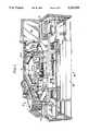
- FIG. 1is a simplified perspective view of an automated analytical instrument constructed according to the teachings of the present invention
- FIG. 2is a perspective view of a plurality of the containers for holding fluid samples for use with the automated analytical instrument shown in FIG. 1;
- FIG. 3is a simplified perspective view taken from the front right of the fluid sample holding tray transport assembly shown in FIG. 1;
- FIG. 4is a perspective view taken from the top of one of the fluid sample holding trays shown in FIG. 1;
- FIG. 5is a bottom view of the fluid sample holding tray shown in FIG. 1;
- FIG. 6is a fragmentary perspective view taken from the left of the sample tray loading unit shown in FIG. 2;
- FIG. 6(a)is a top view of the loading tray shown in FIG. 6;
- FIG. 7is a front view showing a fluid sample holding tray seated on the tray loading unit in FIG. 1;
- FIG. 8is an end view showing the carriage in the transport assembly in FIG. 3 in engagement with a fluid sample holding tray in FIG. 4;
- FIG. 9is a simplified perspective view of those components of the automated analytical instrument of FIG. 1 that pertain to the assay module transport assembly, certain elements of the assay module transport assembly being shown in block form for simplicity and clarity;
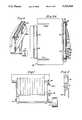
- FIG. 10is a partially exploded perspective view of one of the supply units or segments of the assay module supply apparatus shown in FIG. 1 with a plurality of magazines mounted therein;
- FIG. 11is an enlarged front view, broken away in part, of one of the magazines shown in FIG. 10;
- FIG. 12is a rear perspective view, broken away in part, of the magazine shown in FIG. 11;
- FIG. 13is an enlarged perspective view of one of the assay modules shown in FIG. 11;
- FIG. 14is an enlarged front perspective view of the assay module ejector mechanism shown in FIG. 9;
- FIG. 15is an enlarge top view of the assay module receiving platform shown in FIG. 9;
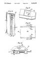
- FIG. 16is an enlarged front view of the cutter assembly shown in FIG. 9;
- FIG. 17is a left side view of the cutter assembly shown in FIG. 16;
- FIG. 18is a right side view of the cutter assembly shown in FIG. 16;
- FIG. 19is an enlarged perspective view of the assay module transport mechanism shown in FIG. 9;
- FIG. 20is a perspective view of the assay module loader assembly shown in FIG. 19.
- FIG. 21is a front view of the loader arm shown in FIG. 20.
- FIG. 1there is shown an automated analytical instrument constructed according to the teachings of the present invention for conducting assays for components of interest in fluid samples, the instrument being identified by reference numeral 15. Portions of instrument 15 not pertinent to this invention are neither shown nor discussed.
- Instrument 15includes an assay module supply apparatus 17 for storing a plurality of unused assay modules each containing one or more reagents useful in the detection of a particular component in a fluid sample.
- Instrument 15also includes a temperature controlled chamber 21 wherein the testing of fluid samples occurs in the manner hereinafter described and an assay module transport assembly 23 for transporting assay modules one at a time, from supply apparatus 17 onto a rotatably mounted turntable 24 disposed within chamber 21.
- Instrument 15further includes a pair of pipette assemblies 25-1 and 25-2 for dispensing quantities of fluid samples to assay modules disposed at a pair of metering stations 26 and 28 (shown schematically) located within chamber 21. In the preferred embodiment illustrated in FIG.
- the metering stationsare located in proximity to turntable 24 and the assay modules are removed from the turntable and deposited at a metering station. Subsequent to receiving the fluid samples the assay elements are returned to the turntable where they reside during the incubation period. It will be appreciated by those skilled in the art that the sample fluid may be deposited on the assay elements prior to their insertion in the temperature-controlled chamber 21 or when the assay elements are located on the turntable.
- the instrument 15additionally includes a plurality of, preferably three, optical read stations (not shown) located within chamber 21 for measuring a signal generated in the assay element which is a function of the concentration of a component of interest in the sample fluid.
- the optical read stationsas is the case with the metering stations 26 and 28, are located in proximity to the turntable 24.
- Automated shuttle mechanisms(not shown) are used to transport assay modules back and forth between turntable 24 and metering stations 26 and 28 and back and forth between turntable 24 and an optical read station.
- Each of the optical read stationshas associated with it an optical read device, one of which is shown at 27 for purposes of illustration. In the preferred embodiment illustrated in FIG.
- Pipette assemblies 25obtain pipette tips 28-1 from a pipette tip holding container 28-2 suitably located within instrument 15.
- Instrument 15also includes a fluid sample holding tray transport assembly 31 (FIG. 3) which serves to transport one or more fluid sample holding trays 29 within instrument 15 as will hereinafter be discussed.
- Each fluid sample holding tray 29is adapted to hold a plurality of sample fluid containers 33.
- a plurality of sample fluid containers 33are shown in FIG. 2.
- Containers 33can take the form of either cups or tubes. For illustrative purposes only, containers 33 are shown as tubes.
- Instrument 15additionally can include a diluent tray 34 for holding diluents and a diluent tray transport assembly 34-1.
- Transport assembly 34-1serves to transport diluent tray 34 to a desired location within instrument 15.
- Transport assembly 34-1includes a rail on which tray 34 is mounted and a motor driven chain attached to tray 34 for moving tray 34 on the rail.
- Instrument 15further includes a microprocessor (not shown) for controlling the operation of the various components within instrument 15. It should be noted that when reference is made herein to a microprocessor it is intended to include the overall controlling processing unit (CPU) as well as any number of embedded single chip controllers each of which is typically utilized to control the operation of one mechanism such as a stepper motor for driving various assemblies as will be described herein. Instrument 15 also preferably includes a CRT screen 35 which can be used to provide a visual display of the assay results obtained from the analyses performed on the instrument. In a preferred embodiment, screen 35 is a touch screen which allows an operator to input information and instructions to the instrument 15. All of the components noted above are supported in a frame 36.
- a microprocessorfor controlling the operation of the various components within instrument 15. It should be noted that when reference is made herein to a microprocessor it is intended to include the overall controlling processing unit (CPU) as well as any number of embedded single chip controllers each of which is typically utilized to control the operation of one mechanism such as a stepper motor for
- Fluid sample holding tray transport assembly 31which is shown separately in FIG. 3, includes a conveyor 37 for moving fluid sample holding trays 29 along a path past pipette assemblies 25, a sample holding tray loading unit 39 for automatically loading fluid sample holding trays 29 onto conveyor 37 and a sample holding tray unloading unit 41 for automatically unloading fluid sample holding trays from conveyor 37.
- FIG. 1two fluid sample holding trays 29 are shown, one at sample tray loading unit 39 and the other at sample tray unloading unit 41; however, it should be understood that the number of fluid sample holding trays 29 shown in FIG. 1 and their locations within instrument 15 are for illustrative purposes only.
- fluid samples to be testedare deposited in fluid sample containers 33.
- Containers 33are then loaded onto trays 29.
- containers 33could be filled after they are loaded into trays 29.
- One or more trays 29are then placed by the operator on loading unit 39, the number of trays 29 placed thereon depending on the number of fluid samples to be tested and the number of trays 29 that can actually fit on loading unit 39.
- each pipette assembly 25takes a tip 25-1 from a holding container 28-2. Trays 29 are placed on loading unit 39 in a row, one behind the other.
- the first tray 29 in the rowis automatically advanced to the tray loading area at the rear of loading unit 39, loaded onto conveyor 37 and then moved by conveyor 37 to a predetermined one of the pipette assemblies 25. After quantities of the desired fluid samples have been aspirated from tray 29 by a pipette assembly, tray 29 is moved along conveyor 37 to unloading unit 41 where it is unloaded from conveyor 37. The next tray 29 in the row is then loaded from loading unit 39 to conveyor 37 and so forth.
- the loading, moving, dispensing, and unloading operationsare all controlled by the microprocessor.
- Tray 29can be molded polymeric structure which is shaped to include a top portion 42 having a plurality of openings 43 in which can be removably mounted containers 33, left and right side flanges 45 and 46, respectively, having slots 47 and 48, respectively, and a bottom wall 49 which includes a longitudinal slot 50 having a pair of integrally formed notches 51 and 53. Openings 43 are shaped and sized according to the shape of the containers 33 being used (i.e. cups or tubes).
- Conveyor 37includes a monorail 55 which extends from loading unit 39 to unloading unit 41 along a path which passes by the pipette assemblies 25-1 and 25-2.
- a carriage 57 adapted to support a fluid sample holding tray 29is slidably mounted on monorail 55.
- Carriage 57includes a pair of spring loaded detents 58 which are used to removably secure carriage 57 to a tray 29 to be transported by carriage 57.
- Carriage 57is fixedly secured to a rotably mounted endless belt 59.
- Belt 59is driven by a reversible stepper motor 61, the operation of which is controlled by the microprocessor. When motor 61 is energized, endless belt 59 will move causing carriage 57 to slidably move along monorail 55, the direction of movement of carriage 57 on monorail 55 depending on the rotation of the drive shaft of motor 61.
- Loading unit 39is an elongated rigid structure and includes a base 63 having front and rear lateral slots 64-1 and 64-2, respectively, a pair of side walls 65 and 67 which extend upwardly on either side of base 63, a front area 69 and a rear area 71.
- Loading unit 39is positioned with respect to conveyor 37 so that rear slot 64-2 is aligned with monorail 55.
- a pair of endless belts 73 and 75are rotably mounted on loading unit 39, one on each side thereof, and extend from the front area 69 of unit 39 to the rear area 71 of unit 39. Endless belts 73 and 75 are driven by a motor 77 which is coupled to both belts.
- Belt 73is disposed lower than belt 75 so as not to interfere with the loading of a tray 29 onto carriage 57 as will hereinafter be explained.
- bottom wall 49will be seated on belt 73 and side flange 46 will be seated on belt 75.
- Motor 77is controlled by the microprocessor.
- Belts 73 and 75are used to carry tray 29 the to rear area 71 of unit 39 where it is automatically transferred to carriage 57.
- An elongated detector plate 79extending from the front area 69 of unit 39 to the rear area 71 of unit 39 is pivotally mounted on the inside surface of outer side wall 67.
- a signal interrupter plate 81is fixedly attached to detector plate 79.
- a first sensor unit 83is mounted on loading unit 39 in close proximity to plate 81.
- sensor unit 83is shown being mounted on the front area 69 of loading unit 39. It will be appreciated that the sensor unit 83 can be mounted at any suitable location along the side of loading unit 39.
- First sensor unit 83includes an LED 83-1 and a light detector 83-2. When there is no tray 29 in loading unit 39, plate 79 is pivoted outward at an angle of about 30 degrees, and detector 83-2 receives a light signal from LED 83-1 and sends an electrical signal to the microprocessor indicating that the light signal is received.
- plate 79When a tray 29 is placed in loading unit 39 at any location along base 63, plate 79 will be pivoted up causing plate 81 to interrupt the signal sent by first sensor unit 83 to the microprocessor. This in turn will cause the microprocessor to activate motor 77.
- Unit 39also includes a 45 degree movable plate 84 which is mounted on the outside of side wall 67. Movable plate 84 is normally in a raised position. Movement of plate 84 is controlled by a solenoid 84-1. Plate 84 serves two purposes, namely, to guide tray 29 as it is moved back in loading unit 39 to rear area 71 and to prevent tray 29 from moving out on monorail 55 until allowed to do so by the microprocessor. When a tray 29 is placed in loading unit 39, plate 84 will extend up in slot 48 of tray 29. Plate 84 can also, where desired, be utilized to serve a latching function, e.g., to restrain tray 29 and prevent it from being moved accidently on the loading unit 39.
- a latching functione.g., to restrain tray 29 and prevent it from being moved accidently on the loading unit 39.
- a signalis sent by a second sensor (not shown), which is identical to sensor 83, to the microprocessor.
- This signalcauses the microprocessor to send out a signal which stops motor 77, which drives belts 73 and 75, and a signal which starts motor 61, which moves carriage 57 on monorail 55 so that it can slide into slot 50 in tray 29.
- spring detents 58 on the top of carriage 57engages the notches 51 and 53 in tray 29, thereby releasably securing carriage 57 to tray 29.
- FIG. 8An end view showing carriage 57 in engagement with tray 29 is shown in FIG. 8.
- a signalis sent to the microprocessor by a third sensor (not shown), which is also identical to sensor 83.
- the signal from the third sensor to the microprocessorcauses it to send out a signal changing the direction of rotation of motor 61 which moves belt 59.
- the microprocessorsends out a signal to solenoid 84-1 which causes plate 84 to be lowered.
- These two signals from the microprocessorwill enable carriage 57 to move back out on monorail 55 carrying with it a tray 29.
- Carriage 57will stop at a pipette assembly, 25-1 or 25-2, the particular pipette assembly being controlled by the microprocessor. After all the fluid samples have been withdrawn from tray 29 for analysis, carriage 57 will transport tray 29 to unloading unit 41.
- Unloading unit 41is similar in construction to loading unit 39 in that it includes a base 91 having front and rear slots 92 and 93, side walls 94 and 95, a pair of belts 96 and 97 driven by a motor (not shown), a detector plate 98 coupled to an interrupter plate (not shown) which is similar to interrupter plate 81 of loading unit 39 (FIG. 6a), a 45 degree movable latch plate 99 and a set of three sensors (not shown). However, detector plate 98 only extends forward a short distance from the rear of the unit. Latch plate 99 is in a normally raised position as is the case with movable plate 84. In order to allow tray 29 to be moved onto unload station 41, latch plate 99 must be lowered.
- a microprocessor-controlled solenoid(not shown) causes latch plate 99 to be lowered.
- latch 99will be raised, carriage 57 will move back out leaving tray 29 on unit 41 and belts 96 and 97 will move tray 29 forward.
- the motorwill be stopped causing belts 96 and 97 to stop movement.
- assay module supply apparatus 17, assay module transport assembly 23, and a portion of turntable 24 of chamber 21are schematically shown and are hereinafter shown and described in detail to illustrate the operation of assay module transport assembly 23.
- supply apparatus 17comprises a cylindrically shaped frame 101, a rotatably mounted, annularly-shaped turntable 103 upon which frame 101 is supported, a stepper motor 105 which is coupled to turntable 103 through a belt (not shown) for rotating turntable 103, a plurality of arcuately shaped assay module supply units or segments 107 (only one of which is shown in FIG. 9 for clarity) which are removably mounted on the outside of frame 101, and a plurality of magazines 109 which are removably mounted in each segment 107.
- the operation and direction of motor 105 and, hence, the rotational position of segments 107are controlled by the microprocessor.
- each segment 107has a plurality of generally rectangularly shaped chambers 111 circumferentially spaced thereon in two sections.
- the back wall of each chamber 111includes a plurality of vertically spaced openings 113 the purpose of which will become apparent below.
- a downwardly-biasing tab 115extends into each chamber 111, tab 115 being used to removably secure magazine 109 within chamber 111 in a snap-lock fashion.
- FIGS. 11 and 12A single magazine 109 is shown in greater detail in FIGS. 11 and 12 (one assay module 19 having been removed from magazine 109 in the manner to be described below, magazine 109 being broken away in part to reveal two additional assay modules 19 contained therewithin).
- magazine 109comprises a generally rectangularly-shaped, open-faced vessel 117.
- Vessel 117is internally sectioned so as to define a plurality of vertically stacked compartments 119, each compartment being further subdivided into a pair of horizontally adjacent sections 121 and 123, respectively, section 121 being used to hold a single assay module 19 (preferably seated therewithin in a nose-in orientation) and section 123 being used to receive a piece of the material covering compartment 119 once it has been cut away therefrom in the manner described below.
- An upwardly biasing tab 124is formed at the rear end of section 121 of each compartment 119.
- Tab 124which is adapted to engage the bottom of an assay module 19, is used to restrict longitudinal movement of the assay module within section 121 of compartment 119 until the appropriate time for its ejection therefrom.
- An opening 125is formed in the back wall of each compartment 119 of vessel 117 to permit access to the nose end of the assay module seated therewithin for reasons to be discussed below.
- openings 125 of vessel 117become aligned with openings 113 of segment 107.
- Sheets of material 127-1 and 127-2which may be a thin foil or other like material for preventing moisture or debris from entering compartments 119 are adhered to the front and rear surfaces, respectively, of vessel 117.
- a label 129 having imprinted thereon a bar code or other similar information readable by a bar code reader or the likeis affixed to the bottom of vessel 117 for purposes of identifying the specificity of the assay modules contained within vessel 117.
- assay module 19is an elongated boat-shaped structure 131 having an inwardly tapering nose 131-1.
- An opening 133is provided inside assay module 19 to provide access to a reagent bearing film 133-1 contained therein.
- assay module transport assembly 23can be seen to include a scaffolding 141.
- Scaffolding 141includes a first pair of legs 143-1 and 143-2 which extend downwardly through the inside of frame 101 and are attached at their bottom ends to a fixed plate 145 concentrically disposed within turntable 103. Plate 145 is coupled to the turntable 103 through a bearing to allow the turntable to rotate while plate 145 remains fixed.
- Scaffolding 141also includes a second pair of legs 147-1 and 147-2 which extend downwardly in front of assay module supply apparatus 17 and are attached at their bottom ends to frame 36.
- Assay module transport assembly 23also includes an assay module ejector mechanism 151, which is used to eject a desired assay module 19 from assay module supply apparatus 17 in the manner to be described below.
- ejector mechanism 151is mounted on a plate 152, which in turn is mounted on a lead screw 153.
- Lead screw 153is coupled to a stepper motor 155 by a belt 157. The operation and direction of motor 155 are controlled by the microprocessor.
- lead screw 153draws plate 152 and, hence, ejector mechanism 151 either up or down depending on the direction in which lead screw 153 is turned by motor 155.
- a guide post 159is additionally provided to prevent plate 152 from rotating due to the turning movement of lead screw 153.
- Assay module transport assembly 23additionally includes an assay module receiving platform 161, which is used to receive an assay module 19 which has been ejected from assay module supply apparatus 17 by assay module ejector mechanism 151.
- Assay module receiving platform 161is mounted on a second elevator-type arrangement comprising a plate 162, a lead screw 163 on which plate 162 is mounted, and a stepper motor 165 to which lead screw 163 is coupled by a belt 167.
- the operation and direction of motor 165is also controlled by the microprocessor.
- a guide post 169is additionally provided to prevent plate 162 from rotating as lead screw 163 is turned.
- Assay module transport assembly 23further includes a cutter assembly 171 which, as will be seen below, is used to tear away that portion of sheet of material 127-1 covering a desired compartment 119 of magazine 109 and then to tuck the torn strip of material into section 123 of compartment 119.
- Cutter assembly 171is fixedly mounted on the bottom of plate 162.
- Assay module transport assembly 23also includes an assay module transfer apparatus 173 which, as will be seen below, serves to move an assay module 19 from assay module receiving platform 161 to an assay module berth 175 formed on turntable 24.
- Board 177which is connected to the microprocessor, includes a pair of bar code readers 179 for reading the bar codes printed on labels 129, the pair of bar code readers 179 being positioned so that one bar code reader 179 reads the bar codes located on the top row of magazines 109 in segment 107 and the other bar code reader 179 reads the bar codes located on the bottom row of magazines 109 in segment 107.
- Board 177also includes a plurality of assay module detectors 181, each detector 181 comprising an LED (not shown) whose output is directed at a specific compartment 119 of magazine 109 and a light detector (not shown) positioned to detect light reflected off the piece of foil 127-1 covering the particular compartment. If the piece of material covering a compartment has not been removed, light emitted by the LED will be reflected off the piece of material and detected by the light detector, indicating that an assay module is present within the compartment. If, however, the piece of material has been removed, then the light emitted by the LED will not be reflected off the piece of material covering the compartment and will not be detected by the light detector, indicating that an assay module is not present within the compartment.
- assay module ejector mechanism 151includes an elongated supporting bracket 183, which is adapted to be mounted on plate 152 (see FIG. 9).
- a supporting rod 185extends along the length of bracket 183 and is mounted at the opposite ends thereof.
- a slider block 187is mounted on rod 185 for forward and rearward longitudinal sliding movement thereon.
- a pusher rod 189which, as will be seen below, is used to pierce layer of material 127-2 and push an assay module 19 from magazine 109 onto assay module receiving platform 161, is mounted on the leading end of slider block 187.
- Slider block 187is fixedly attached by any suitable means, not shown, to an endless belt 191 which is mounted for movement along a path defined by wheels 192, 193, 194, and 195.
- Belt 191is driven by a stepper motor 197 whose output shaft is fixedly attached to wheel 195.
- the operation and direction of stepper motor 197is controlled by the microprocessor.
- assay module receiving platform 161includes a pair of outwardly extending flanges 201-1 and 201-2 adapted to receive a screw or the like for securing platform 161 to plate 162 (see FIG. 9) and a generally rectangularly shaped trough 203 dimensioned to correspond generally to the size and shape of an assay module 19.
- a pair of inwardly biasing clips 205-1 and 205-2are mounted on trough 203 to provide a small amount of resistance so that an assay module 19 will not be pushed too far across trough 203 as a result of the force imparted to the assay module 19 by pusher rod 189 of ejector mechanism 151.
- cutter assembly 171includes a generally C-shaped supporting bracket 207, which is adapted to be mounted on the bottom of plate 162 (see FIG. 9) with a pair of screws 209-1 and 209-2.
- a block 211is slidably mounted inside bracket 207.
- One end of block 211is shaped to define a cylindrically-shaped, finger-like projection or plunger 213.
- plunger 213is used to tuck the piece of material from layer 127-1 which has been cut in the manner hereinafter described into section 123 of compartment 119.
- Cutter assembly 171also includes a generally C-shaped cutter element 221.
- Cutter element 221is slidably mounted on block 211 but is biased towards plunger 213 by a pair of springs 223-1 and 223-2, which are mounted at one end on a pair of posts 225-1 and 225-2, respectively, fixedly attached to block 211 and at their opposite ends on a pair of posts 227-1 and 227-2, respectively, fixedly attached to the sides of cutter element 221.
- the transverse portion of cutter element 221includes an opening 229 through which plunger 213 of block 211 extends when element 221 is moved relative to block 211 in the manner discussed below.
- the transverse portion of cutter element 221also includes a blade element 231 which, as will hereinafter be discussed, is used to cut that portion of material layer 127-1 covering three sides, for example, the top, bottom, and right side edges of compartment 119.
- assay module transfer mechanism 173includes a platform 233.
- Platform 233is rotatably mounted on a shaft (not shown) which is coupled through a belt (not shown) to a stepper motor 235.
- the operation and direction of stepper motor 235are controlled by the microprocessor.
- Mounted on top of platform 233is an assay module loader assembly 237. As can be seen in FIG.
- assay module loader assembly 237is virtually identical in construction to assay module ejector mechanism 151, the only difference between assay module loader assembly 237 and assay module ejector mechanism 151 being that assay module loader assembly 237 does not have a pusher rod 189 mounted on the leading end of slider block 187, but rather, has a loader arm 239, which is fixedly mounted with a screw or similar means on the front side of slider block 187. Loader arm 239, which is shown in isolation in FIG.
- assay module transfer mechanism 173When assay module transport apparatus 23 is not in use, assay module transfer mechanism 173 is positioned so that platform 233 is rotated towards chamber 21 and loader arm 239 is fully extended over turntable 24. When actuation of assay module transport assembly 23 is desired, turntable 24 is rotated until a used and no longer needed assay module seated on turntable 24 comes into engagement with loader arm 239. Loader arm 239 then retracts, pulling the used assay module onto platform 233 and leaving an empty assay module berth 175 on turntable 24. Next, platform 233 makes an approximately quarter-turn rotation after which loader arm 239 extends again, ejecting the used assay module from platform 233 into a used assay module receptacle (not shown). Loader arm 239 then retracts again and platform 233 rotates until loader arm 239 is aligned with assay module receiving platform 161.
- turntable 103rotates, if necessary, so that the magazine 109 containing the assay module which it is desired to remove therefrom becomes rotationally aligned with cutter assembly 171.
- Plate 162is moved vertically, if necessary, so that cutter assembly 171 is aligned vertically with the compartment 119 containing the desired assay module.
- the rack and pinion arrangement of cutter assembly 171drives block 211 (and, hence, cutter element 221) horizontally towards the compartment 119 containing the desired assay module.
- This horizontal movementcauses blade element 231 of cutter element 221 to sever three sides, for example, the top, bottom, and right side edges of that portion of the layer of material 127-1 covering compartment 119; however, further horizontal movement of cutter element 221 towards compartment 119 is restrained as the remaining surface of the transverse portion of cutter element 221 comes into contact with that portion of vessel 117 surrounding the compartment 119.
- block 211continues to move horizontally in the direction of compartment 119, causing plunger 213 to extend through opening 229 of cutting element 221 in such a way as to push the now torn piece of the layer of material 127-1 into section 123 of compartment 119.
- the rack and pinion arrangementthen reverses direction causing block 211 and cutting element 221 to retract.
- Plate 162then moves downwardly so that assay module receiving platform 161 is aligned vertically with the compartment 119 containing the desired assay module. Either at the same time, before, or after the above-recited sequence of events, plate 152 is moved vertically, if necessary, so that pusher rod 189 of assay module ejector mechanism 151 is vertically aligned with the compartment 119 containing the desired assay module.
- Pusher rod 189is then moved horizontally towards the desired compartment 119 whereby it passes through the opening 113 on the back of the segment 107, pierces that portion of the layer of material 127-2 covering opening 125 of the desired compartment 119, passes through opening 125, and pushes the nose end 131-1 of the desired assay module 19 out of compartment 119 and onto platform 161. Pusher rod 189 is then retracted.
- plate 162With the desired assay module now on assay module receiving platform 161, plate 162 then moves vertically, if necessary, to a waiting position just below the plane of loader arm 239. Loader arm 239 is then extended, and plate 162 moves vertically upwardly until the assay module on platform 161 engages tabs 243-1 and 243-2 of loader arm 239. Loader arm 239 then retracts, pulling the assay module off platform 161 and onto platform 233. Platform 233 then rotates so that loader arm 239 is aligned with the empty assay module berth 175 on turntable 24, and loader arm 239 is extended so that the desired assay module is inserted into the empty berth 175. Turntable 24 then rotates so that the new assay module is no longer aligned with loader arm 239. Loader arm 239 is then ready to receive another used assay module disposed on turntable 24 and the above-described sequence of events may be repeated.
Landscapes
- Physics & Mathematics (AREA)
- Health & Medical Sciences (AREA)
- Life Sciences & Earth Sciences (AREA)
- Chemical & Material Sciences (AREA)
- Analytical Chemistry (AREA)
- Biochemistry (AREA)
- General Health & Medical Sciences (AREA)
- General Physics & Mathematics (AREA)
- Immunology (AREA)
- Pathology (AREA)
- Automatic Analysis And Handling Materials Therefor (AREA)
Abstract
Description
Claims (9)
Priority Applications (6)
| Application Number | Priority Date | Filing Date | Title |
|---|---|---|---|
| US07/908,191US5332549A (en) | 1992-07-01 | 1992-07-01 | Assay module transport apparatus for use in an automated analytical instrument |
| PCT/US1993/006133WO1994001780A2 (en) | 1992-07-01 | 1993-06-28 | Assay module transport apparatus for use in an automated analytical instrument |
| CA002149433ACA2149433A1 (en) | 1992-07-01 | 1993-06-28 | Assay module transport apparatus for use in an automated analytical instrument |
| EP93916807AEP0648337A1 (en) | 1992-07-01 | 1993-06-28 | Assay module transport apparatus for use in an automated analytical instrument |
| AU46537/93AAU671663B2 (en) | 1992-07-01 | 1993-06-28 | Assay module transport apparatus for use in an automated analytical instrument |
| US08/172,775US5460778A (en) | 1992-07-01 | 1993-12-27 | Cutting apparatus for use in an automated analytical instrument |
Applications Claiming Priority (1)
| Application Number | Priority Date | Filing Date | Title |
|---|---|---|---|
| US07/908,191US5332549A (en) | 1992-07-01 | 1992-07-01 | Assay module transport apparatus for use in an automated analytical instrument |
Related Child Applications (1)
| Application Number | Title | Priority Date | Filing Date |
|---|---|---|---|
| US08/172,775DivisionUS5460778A (en) | 1992-07-01 | 1993-12-27 | Cutting apparatus for use in an automated analytical instrument |
Publications (1)
| Publication Number | Publication Date |
|---|---|
| US5332549Atrue US5332549A (en) | 1994-07-26 |
Family
ID=25425343
Family Applications (2)
| Application Number | Title | Priority Date | Filing Date |
|---|---|---|---|
| US07/908,191Expired - LifetimeUS5332549A (en) | 1992-07-01 | 1992-07-01 | Assay module transport apparatus for use in an automated analytical instrument |
| US08/172,775Expired - Fee RelatedUS5460778A (en) | 1992-07-01 | 1993-12-27 | Cutting apparatus for use in an automated analytical instrument |
Family Applications After (1)
| Application Number | Title | Priority Date | Filing Date |
|---|---|---|---|
| US08/172,775Expired - Fee RelatedUS5460778A (en) | 1992-07-01 | 1993-12-27 | Cutting apparatus for use in an automated analytical instrument |
Country Status (5)
| Country | Link |
|---|---|
| US (2) | US5332549A (en) |
| EP (1) | EP0648337A1 (en) |
| AU (1) | AU671663B2 (en) |
| CA (1) | CA2149433A1 (en) |
| WO (1) | WO1994001780A2 (en) |
Cited By (69)
| Publication number | Priority date | Publication date | Assignee | Title |
|---|---|---|---|---|
| US5419871A (en)* | 1994-04-29 | 1995-05-30 | Muszak; Martin F. | Analyzer elevator assembly |
| US5489414A (en)* | 1993-04-23 | 1996-02-06 | Boehringer Mannheim, Gmbh | System for analyzing compounds contained in liquid samples |
| US5518693A (en)* | 1994-06-27 | 1996-05-21 | Johnson & Johnson Clinical Diagnostics, Inc. | Transfer mechanism for automatic loading and unloading of reagent modules |
| US5567387A (en)* | 1994-11-07 | 1996-10-22 | Johnson & Johnson Clinical Diagnostics, Inc. | Cuvette conveyor and sensor |
| US5690892A (en)* | 1995-09-15 | 1997-11-25 | Accumed, Inc. | Cassette for use with automated specimen handling system |
| US5930732A (en)* | 1995-09-15 | 1999-07-27 | Accumed International, Inc. | System for simplifying the implementation of specified functions |
| US5928952A (en)* | 1997-11-05 | 1999-07-27 | Zymark Corporation | Scheduled system and method for processing chemical products |
| US5985214A (en)* | 1997-05-16 | 1999-11-16 | Aurora Biosciences Corporation | Systems and methods for rapidly identifying useful chemicals in liquid samples |
| US6060022A (en)* | 1996-07-05 | 2000-05-09 | Beckman Coulter, Inc. | Automated sample processing system including automatic centrifuge device |
| US6091842A (en)* | 1996-10-25 | 2000-07-18 | Accumed International, Inc. | Cytological specimen analysis system with slide mapping and generation of viewing path information |
| JP2000214173A (en)* | 1999-01-23 | 2000-08-04 | Roche Diagnostics Gmbh | Method and apparatus for taking out consumed analysis object from storage container |
| US6118581A (en)* | 1995-09-15 | 2000-09-12 | Accumed International, Inc. | Multifunctional control unit for a microscope |
| EP0951939A3 (en)* | 1998-04-24 | 2001-01-10 | Roche Diagnostics GmbH | Storage container for analytical test elements |
| US6184040B1 (en) | 1998-02-12 | 2001-02-06 | Polaroid Corporation | Diagnostic assay system and method |
| US6299840B1 (en)* | 1998-04-02 | 2001-10-09 | Matsushita Electric Industrial Co., Ltd. | Automatic testing apparatus |
| US6323035B1 (en)* | 1997-09-24 | 2001-11-27 | Glaxo Wellcome, Inc. | Systems and methods for handling and manipulating multi-well plates |
| US6328930B1 (en) | 1999-02-11 | 2001-12-11 | Polaroid Corporation | Apparatus for performing diagnostic testing |
| US6331715B1 (en) | 1998-10-14 | 2001-12-18 | Polaroid Corporation | Diagnostic assay system and method having a luminescent readout signal |
| US6361745B1 (en)* | 1999-09-08 | 2002-03-26 | Packard Instrument Company, Inc. | Microarray storage device for use in an automated microarray handling system |
| BE1013576A3 (en)* | 2000-06-28 | 2002-04-02 | Staar Sa | Input device and delivery of objects. |
| US20020064867A1 (en)* | 1997-05-23 | 2002-05-30 | Becton Dickinson Company | Automated microbiological testing apparatus and method therefor |
| US6495373B1 (en) | 1998-10-14 | 2002-12-17 | Polaroid Corporation | Method and apparatus for performing diagnostic tests |
| US20030032191A1 (en)* | 2001-07-30 | 2003-02-13 | Hilson Richard O. | Sample processing apparatus and methods |
| US20030036200A1 (en)* | 2001-08-20 | 2003-02-20 | Charlton Steven C. | Packaging system for test sensors |
| US20030037624A1 (en)* | 2001-08-23 | 2003-02-27 | Cybio Instruments Gmbh | Automatic tip changer for automatic multipipettors |
| US6555060B1 (en) | 1998-10-14 | 2003-04-29 | Polaroid Corporation | Apparatus for performing diagnostic testing |
| US20030091413A1 (en)* | 2001-11-09 | 2003-05-15 | Yergenson Robin P. | Object retention in a rotatable carousel |
| US20030118487A1 (en)* | 2001-10-19 | 2003-06-26 | Monogen, Inc. | Article handling system and method |
| US6605213B1 (en) | 1998-05-01 | 2003-08-12 | Gen-Probe Incorporated | Method and apparatus for performing a magnetic separation purification procedure on a sample solution |
| US6641782B1 (en) | 2000-11-15 | 2003-11-04 | Polaroid Corporation | Apparatus for performing diagnostic testing |
| US20030215357A1 (en)* | 2002-05-13 | 2003-11-20 | Nigel Malterer | Automated processing system and method of using same |
| US6656428B1 (en) | 1999-08-06 | 2003-12-02 | Thermo Biostar, Inc. | Automated point of care detection system including complete sample processing capabilities |
| EP1416274A1 (en)* | 2002-10-29 | 2004-05-06 | Roche Diagnostics GmbH | Test device system |
| US6746648B1 (en) | 2000-06-15 | 2004-06-08 | Beckman Coulter, Inc. | Method and system for transporting and storing multiple reagent packs and reagent packs used therein |
| US20040170082A1 (en)* | 2003-01-24 | 2004-09-02 | Hubert Heeg | Shaking incubator |
| US20050013747A1 (en)* | 2003-07-18 | 2005-01-20 | Thai Huynh-Ba | Magazine for inventorying reaction cuvettes in an automatic analyzer |
| US20050035143A1 (en)* | 2003-08-15 | 2005-02-17 | Peter Massaro | Method and apparatus for handling small volume fluid samples |
| US20050089446A1 (en)* | 2003-10-28 | 2005-04-28 | Biomerieux, Inc. | Transport system for test sample carrier |
| US20070009381A1 (en)* | 2003-12-24 | 2007-01-11 | Jochen Schulat | Hand-held analysis device |
| US20070010019A1 (en)* | 2001-04-24 | 2007-01-11 | Luoma Robert P Ii | Assay testing diagnostic analyzer |
| KR100706007B1 (en)* | 1998-04-24 | 2007-04-11 | 로셰 디아그노스틱스 게엠베하 | Analysis device storage container and analysis device storage system |
| US7208119B1 (en)* | 2000-03-01 | 2007-04-24 | Roche Diagnostics Operations, Inc. | Hospital meter system |
| US7303725B2 (en)* | 2002-04-15 | 2007-12-04 | Ventana Medical Systems, Inc. | Automated high volume slide staining system |
| US20080190735A1 (en)* | 2001-04-24 | 2008-08-14 | Abbott Laboratories | Assay testing diagnostic analyzer |
| US7468161B2 (en) | 2002-04-15 | 2008-12-23 | Ventana Medical Systems, Inc. | Automated high volume slide processing system |
| US7547516B2 (en) | 2005-03-10 | 2009-06-16 | Gen-Probe Incorporated | Method for reducing the presence of amplification inhibitors in a reaction receptacle |
| US20100111765A1 (en)* | 2005-05-04 | 2010-05-06 | Abbott Laboratories | Reagent and sample handling device for automatic testing system |
| US20100129789A1 (en)* | 2007-04-06 | 2010-05-27 | Brian Austin Self | Automated assay and system |
| US20110213492A1 (en)* | 2010-02-26 | 2011-09-01 | William Michael Lafferty | Transfer station for plant material sampling and tracking system |
| US8192992B2 (en) | 1998-05-01 | 2012-06-05 | Gen-Probe Incorporated | System and method for incubating the contents of a reaction receptacle |
| EP2463030A1 (en)* | 2010-12-08 | 2012-06-13 | F. Hoffmann-La Roche AG | Storage assembly for providing reagent carriers for being processed in an analyzing system |
| US8703492B2 (en) | 2007-04-06 | 2014-04-22 | Qiagen Gaithersburg, Inc. | Open platform hybrid manual-automated sample processing system |
| US8718948B2 (en) | 2011-02-24 | 2014-05-06 | Gen-Probe Incorporated | Systems and methods for distinguishing optical signals of different modulation frequencies in an optical signal detector |
| AU2010346613B2 (en)* | 2010-02-26 | 2015-02-12 | Syngenta Participations Ag | Transfer station for plant material sampling and tracking system |
| US9046507B2 (en) | 2010-07-29 | 2015-06-02 | Gen-Probe Incorporated | Method, system and apparatus for incorporating capacitive proximity sensing in an automated fluid transfer procedure |
| US9513303B2 (en) | 2013-03-15 | 2016-12-06 | Abbott Laboratories | Light-blocking system for a diagnostic analyzer |
| US9632103B2 (en) | 2013-03-15 | 2017-04-25 | Abbott Laboraties | Linear track diagnostic analyzer |
| US9953141B2 (en) | 2009-11-18 | 2018-04-24 | Becton, Dickinson And Company | Laboratory central control unit method and system |
| US9993820B2 (en) | 2013-03-15 | 2018-06-12 | Abbott Laboratories | Automated reagent manager of a diagnostic analyzer system |
| CN108169231A (en)* | 2018-01-24 | 2018-06-15 | 南京图思灵智能科技有限责任公司 | A kind of pathological section scanner of large capacity |
| US10031085B2 (en) | 2014-07-24 | 2018-07-24 | Ortho-Clinical Diagnostics, Inc. | Point of care analytical processing system |
| US10184862B2 (en) | 2008-11-12 | 2019-01-22 | Ventana Medical Systems, Inc. | Methods and apparatuses for heating slides carrying specimens |
| CN110168380A (en)* | 2016-11-18 | 2019-08-23 | 塞弗德公司 | Sample treatment modules array processing system and method |
| DE102009028553B4 (en)* | 2008-11-24 | 2019-10-31 | Comde Computer Meßtechnik Design und Entwicklungs GmbH | Measuring element for dust measurement, device for producing at least one measuring element for dust measurement and storage device for at least one measuring element for dust measurement |
| US10794805B2 (en) | 2013-12-13 | 2020-10-06 | Ventana Medical Systems, Inc. | Automated histological processing of biological specimens and associated technology |
| US11249095B2 (en) | 2002-04-15 | 2022-02-15 | Ventana Medical Systems, Inc. | Automated high volume slide processing system |
| US11422140B1 (en)* | 2018-11-28 | 2022-08-23 | Elemental Scientific, Inc. | Autosampler sample probe arm mount |
| CN115128005A (en)* | 2022-07-13 | 2022-09-30 | 山东志盈医学科技有限公司 | A rotating material box device for a high-throughput digital slice scanner |
| US12110535B2 (en)* | 2013-03-14 | 2024-10-08 | Gen-Probe Incorporated | Method for reconstituting a reagent |
Families Citing this family (21)
| Publication number | Priority date | Publication date | Assignee | Title |
|---|---|---|---|---|
| EP0632271B1 (en)* | 1993-07-01 | 1999-04-28 | Johnson & Johnson Clinical Diagnostics, Inc. | Improved transfer mechanism for automatic loading and unloading of reagent modules |
| AU715627B2 (en)* | 1996-02-21 | 2000-02-03 | Biomerieux Vitek, Inc. | Automatic sample testing machine |
| DE29712535U1 (en)* | 1997-07-16 | 1997-09-18 | Bodenseewerk Perkin-Elmer GmbH, 88662 Überlingen | Sample delivery device |
| DE29806303U1 (en) | 1998-04-06 | 1998-09-03 | Archytas Automation GmbH, 85356 Freising | Device for handling and successively positioning a plurality of individual sample containers |
| US6562299B1 (en)* | 1998-09-18 | 2003-05-13 | Cytyc Corporation | Method and apparatus for preparing cytological specimens |
| US20030059347A1 (en) | 1998-09-18 | 2003-03-27 | Roy A. Ostgaard | Sample vial for use in preparing cytological specimen |
| US6572824B1 (en) | 1998-09-18 | 2003-06-03 | Cytyc Corporation | Method and apparatus for preparing cytological specimens |
| DE20006548U1 (en)* | 2000-04-08 | 2001-08-23 | MWG-BIOTECH AG, 85560 Ebersberg | Device for carrying out chemical or biological processes |
| DE20006549U1 (en)* | 2000-04-08 | 2001-08-16 | MWG-BIOTECH AG, 85560 Ebersberg | Device for carrying out chemical or biological processes |
| US7138089B2 (en)* | 2000-07-20 | 2006-11-21 | Hypoguard Limited | Test device for analyzing blood glucose or other analytes in bodily fluids |
| DE20220550U1 (en) | 2001-01-26 | 2003-12-04 | Liconic Ag | Air-conditioned storage cabinet |
| DE10155460A1 (en)* | 2001-11-12 | 2003-05-28 | Kendro Lab Prod Gmbh | Detachable holder used for object support cassette comprises centering strip interacting with complementary centering opening |
| DE10232680A1 (en)* | 2002-07-18 | 2004-02-12 | Siemens Ag | Automatic optical analysis of contrast agents at living cell cultures/medication effects on small animals, uses robot arm which moves samples in and out of chamber where light from samples is detected for evaluation |
| WO2010132885A2 (en) | 2009-05-15 | 2010-11-18 | Gen-Probe Incorporated | Method and apparatus for effecting transfer of reaction receptacles in an instrument for multi-step analytical procedures |
| US8475739B2 (en) | 2011-09-25 | 2013-07-02 | Theranos, Inc. | Systems and methods for fluid handling |
| US9632102B2 (en) | 2011-09-25 | 2017-04-25 | Theranos, Inc. | Systems and methods for multi-purpose analysis |
| US9664702B2 (en) | 2011-09-25 | 2017-05-30 | Theranos, Inc. | Fluid handling apparatus and configurations |
| US20140170735A1 (en) | 2011-09-25 | 2014-06-19 | Elizabeth A. Holmes | Systems and methods for multi-analysis |
| US9810704B2 (en) | 2013-02-18 | 2017-11-07 | Theranos, Inc. | Systems and methods for multi-analysis |
| US10012664B2 (en) | 2011-09-25 | 2018-07-03 | Theranos Ip Company, Llc | Systems and methods for fluid and component handling |
| US11545241B1 (en) | 2013-09-07 | 2023-01-03 | Labrador Diagnostics Llc | Systems and methods for analyte testing and data management |
Citations (25)
| Publication number | Priority date | Publication date | Assignee | Title |
|---|---|---|---|---|
| US4152390A (en)* | 1976-12-17 | 1979-05-01 | Eastman Kodak Company | Chemical analyzer |
| US4151931A (en)* | 1978-06-05 | 1979-05-01 | Eastman Kodak Company | Article dispenser apparatus for use in an automated chemical analyzer |
| US4187077A (en)* | 1978-06-05 | 1980-02-05 | Eastman Kodak Company | Container with article positioning element for dispensing reagent coated slides to an automated analyzer |
| US4190420A (en)* | 1978-06-05 | 1980-02-26 | Eastman Kodak Company | Container for dispensing articles to an automated analyzer |
| US4224032A (en)* | 1976-12-17 | 1980-09-23 | Eastman Kodak Company | Method and apparatus for chemical analysis |
| USRE30595E (en)* | 1978-06-05 | 1981-04-28 | Eastman Kodak Company | Article container for dispensing reagent slides |
| US4269803A (en)* | 1979-07-02 | 1981-05-26 | Eastman Kodak Company | Slide transfer mechanism |
| US4279861A (en)* | 1979-05-09 | 1981-07-21 | Eastman Kodak Company | Cartridge discriminator for an automated analysis system |
| US4296070A (en)* | 1980-06-16 | 1981-10-20 | Eastman Kodak Company | Slide distributor for a chemical analyzer |
| US4325909A (en)* | 1980-10-24 | 1982-04-20 | Coulter Electronics, Inc. | Fluid transfer apparatus |
| US4512952A (en)* | 1982-07-01 | 1985-04-23 | Eastman Kodak Company | Apparatus for storing and dispensing analysis slides |
| US4582990A (en)* | 1980-10-27 | 1986-04-15 | Randam Electronics, Inc. | Analytical instrument with two moving trains of sample holder-carrying trays under microprocessor control |
| US4595562A (en)* | 1981-07-20 | 1986-06-17 | American Hospital Supply Corporation | Loading and transfer assembly for chemical analyzer |
| US4678752A (en)* | 1985-11-18 | 1987-07-07 | Becton, Dickinson And Company | Automatic random access analyzer |
| US4738825A (en)* | 1985-02-27 | 1988-04-19 | Fisher Scientific Company | Cuvette handling |
| US4844868A (en)* | 1985-06-18 | 1989-07-04 | Kabushiki Kaisha Toshiba | Automatic chemical analysis reagent distribution and analysis apparatus |
| US4855109A (en)* | 1986-02-07 | 1989-08-08 | Fuji Photo Film Co., Ltd. | Chemical analysis apparatus |
| US4857471A (en)* | 1987-07-20 | 1989-08-15 | Eastman Kodak Company | Analyzer with wash station separate from incubator |
| JPH01301167A (en)* | 1988-05-30 | 1989-12-05 | Toshiba Corp | automatic chemical analyzer |
| US4965049A (en)* | 1986-07-11 | 1990-10-23 | Beckman Instruments, Inc. | Modular analyzer system |
| US5055262A (en)* | 1988-02-22 | 1991-10-08 | Olympus Optical Co., Ltd. | Automatic cuvette loading apparatus |
| US5066135A (en)* | 1988-08-09 | 1991-11-19 | Beckman Instruments, Inc. | Rotatable vortexing turntable |
| US5075079A (en)* | 1990-05-21 | 1991-12-24 | Technicon Instruments Corporation | Slide analysis system |
| US5104621A (en)* | 1986-03-26 | 1992-04-14 | Beckman Instruments, Inc. | Automated multi-purpose analytical chemistry processing center and laboratory work station |
| US5176880A (en)* | 1989-07-24 | 1993-01-05 | Tosoh Corporation | Automated biochemical analyzer |
Family Cites Families (10)
| Publication number | Priority date | Publication date | Assignee | Title |
|---|---|---|---|---|
| US3348418A (en)* | 1963-08-13 | 1967-10-24 | Intertech Inc | Automatic sample changer |
| US4118280A (en)* | 1976-05-03 | 1978-10-03 | Mcdonnell Douglas Corporation | Automated microbial analyzer |
| JPS5754838A (en)* | 1980-09-18 | 1982-04-01 | Omron Tateisi Electronics Co | Automatic specimen feeder |
| US4876204A (en)* | 1984-10-11 | 1989-10-24 | Kabushiki Kaisha Kyoto Daiichi Kagaku | Method and apparatus of automatic continuous analysis using analytical implement |
| JPH0697305B2 (en)* | 1986-02-18 | 1994-11-30 | 株式会社日立製作所 | Slide specimen placement device |
| JPS62273456A (en)* | 1986-05-21 | 1987-11-27 | Tosoh Corp | Seal breaker for breaking seal foil of test cup used for analyzer |
| US4840011A (en)* | 1987-09-28 | 1989-06-20 | Jujo Paper Co., Ltd. | Device for laterally cutting carton case in carton automatic feeding device for a liquid filling machine |
| NL8901674A (en)* | 1989-06-30 | 1991-01-16 | Ltf Transporttechniek Bv | METHOD FOR OPENING AND EMPTYING VESSELS WITH CHEMICAL WASTE, AND AN APPARATUS FOR CARRYING OUT THIS METHOD |
| US5165316A (en)* | 1991-07-01 | 1992-11-24 | Laclede Chain Manufacturing Company | Chain merchandising apparatus |
| DE69208241T2 (en)* | 1991-07-18 | 1996-07-18 | Behring Diagnostics Inc | DEVICE FOR TRANSPORTING SAMPLES IN AN AUTOMATIC ANALYZER |
- 1992
- 1992-07-01USUS07/908,191patent/US5332549A/ennot_activeExpired - Lifetime
- 1993
- 1993-06-28CACA002149433Apatent/CA2149433A1/ennot_activeAbandoned
- 1993-06-28EPEP93916807Apatent/EP0648337A1/ennot_activeWithdrawn
- 1993-06-28WOPCT/US1993/006133patent/WO1994001780A2/ennot_activeApplication Discontinuation
- 1993-06-28AUAU46537/93Apatent/AU671663B2/ennot_activeCeased
- 1993-12-27USUS08/172,775patent/US5460778A/ennot_activeExpired - Fee Related
Patent Citations (25)
| Publication number | Priority date | Publication date | Assignee | Title |
|---|---|---|---|---|
| US4224032A (en)* | 1976-12-17 | 1980-09-23 | Eastman Kodak Company | Method and apparatus for chemical analysis |
| US4152390A (en)* | 1976-12-17 | 1979-05-01 | Eastman Kodak Company | Chemical analyzer |
| US4151931A (en)* | 1978-06-05 | 1979-05-01 | Eastman Kodak Company | Article dispenser apparatus for use in an automated chemical analyzer |
| US4187077A (en)* | 1978-06-05 | 1980-02-05 | Eastman Kodak Company | Container with article positioning element for dispensing reagent coated slides to an automated analyzer |
| US4190420A (en)* | 1978-06-05 | 1980-02-26 | Eastman Kodak Company | Container for dispensing articles to an automated analyzer |
| USRE30595E (en)* | 1978-06-05 | 1981-04-28 | Eastman Kodak Company | Article container for dispensing reagent slides |
| US4279861A (en)* | 1979-05-09 | 1981-07-21 | Eastman Kodak Company | Cartridge discriminator for an automated analysis system |
| US4269803A (en)* | 1979-07-02 | 1981-05-26 | Eastman Kodak Company | Slide transfer mechanism |
| US4296070A (en)* | 1980-06-16 | 1981-10-20 | Eastman Kodak Company | Slide distributor for a chemical analyzer |
| US4325909A (en)* | 1980-10-24 | 1982-04-20 | Coulter Electronics, Inc. | Fluid transfer apparatus |
| US4582990A (en)* | 1980-10-27 | 1986-04-15 | Randam Electronics, Inc. | Analytical instrument with two moving trains of sample holder-carrying trays under microprocessor control |
| US4595562A (en)* | 1981-07-20 | 1986-06-17 | American Hospital Supply Corporation | Loading and transfer assembly for chemical analyzer |
| US4512952A (en)* | 1982-07-01 | 1985-04-23 | Eastman Kodak Company | Apparatus for storing and dispensing analysis slides |
| US4738825A (en)* | 1985-02-27 | 1988-04-19 | Fisher Scientific Company | Cuvette handling |
| US4844868A (en)* | 1985-06-18 | 1989-07-04 | Kabushiki Kaisha Toshiba | Automatic chemical analysis reagent distribution and analysis apparatus |
| US4678752A (en)* | 1985-11-18 | 1987-07-07 | Becton, Dickinson And Company | Automatic random access analyzer |
| US4855109A (en)* | 1986-02-07 | 1989-08-08 | Fuji Photo Film Co., Ltd. | Chemical analysis apparatus |
| US5104621A (en)* | 1986-03-26 | 1992-04-14 | Beckman Instruments, Inc. | Automated multi-purpose analytical chemistry processing center and laboratory work station |
| US4965049A (en)* | 1986-07-11 | 1990-10-23 | Beckman Instruments, Inc. | Modular analyzer system |
| US4857471A (en)* | 1987-07-20 | 1989-08-15 | Eastman Kodak Company | Analyzer with wash station separate from incubator |
| US5055262A (en)* | 1988-02-22 | 1991-10-08 | Olympus Optical Co., Ltd. | Automatic cuvette loading apparatus |
| JPH01301167A (en)* | 1988-05-30 | 1989-12-05 | Toshiba Corp | automatic chemical analyzer |
| US5066135A (en)* | 1988-08-09 | 1991-11-19 | Beckman Instruments, Inc. | Rotatable vortexing turntable |
| US5176880A (en)* | 1989-07-24 | 1993-01-05 | Tosoh Corporation | Automated biochemical analyzer |
| US5075079A (en)* | 1990-05-21 | 1991-12-24 | Technicon Instruments Corporation | Slide analysis system |
Cited By (191)
| Publication number | Priority date | Publication date | Assignee | Title |
|---|---|---|---|---|
| US5489414A (en)* | 1993-04-23 | 1996-02-06 | Boehringer Mannheim, Gmbh | System for analyzing compounds contained in liquid samples |
| US5645798A (en)* | 1993-04-23 | 1997-07-08 | Boehringer Mannheim Gmbh | Test elements in sealed chambers for analyzing compounds contained in liquid samples |
| US5720924A (en)* | 1993-04-23 | 1998-02-24 | Boehringer Mannheim Gmbh | Storage system for test elements |
| US5863800A (en)* | 1993-04-23 | 1999-01-26 | Boehringer Mannheim Gmbh | Storage system for test elements |
| US5419871A (en)* | 1994-04-29 | 1995-05-30 | Muszak; Martin F. | Analyzer elevator assembly |
| US5518693A (en)* | 1994-06-27 | 1996-05-21 | Johnson & Johnson Clinical Diagnostics, Inc. | Transfer mechanism for automatic loading and unloading of reagent modules |
| US5567387A (en)* | 1994-11-07 | 1996-10-22 | Johnson & Johnson Clinical Diagnostics, Inc. | Cuvette conveyor and sensor |
| US6118581A (en)* | 1995-09-15 | 2000-09-12 | Accumed International, Inc. | Multifunctional control unit for a microscope |
| US5690892A (en)* | 1995-09-15 | 1997-11-25 | Accumed, Inc. | Cassette for use with automated specimen handling system |
| US5930732A (en)* | 1995-09-15 | 1999-07-27 | Accumed International, Inc. | System for simplifying the implementation of specified functions |
| US6060022A (en)* | 1996-07-05 | 2000-05-09 | Beckman Coulter, Inc. | Automated sample processing system including automatic centrifuge device |
| US20090047179A1 (en)* | 1996-07-05 | 2009-02-19 | Ping Wing S | Automated sample processing system |
| US8038942B2 (en) | 1996-07-05 | 2011-10-18 | Beckman Coulter, Inc. | Automated sample processing system |
| US6091842A (en)* | 1996-10-25 | 2000-07-18 | Accumed International, Inc. | Cytological specimen analysis system with slide mapping and generation of viewing path information |
| US6372185B1 (en) | 1997-05-16 | 2002-04-16 | Aurora Biosciences Corporation | Liquid chemical distribution method and apparatus |
| US6472218B1 (en) | 1997-05-16 | 2002-10-29 | Vertex Pharmaceuticals (San Diego), Llc | Systems and methods for rapidly identifying useful chemicals in liquid samples |
| US6685884B2 (en) | 1997-05-16 | 2004-02-03 | Vertex Pharmaceuticals, Inc. | Methods for rapidly identifying useful chemicals in liquid sample |
| US6890485B1 (en) | 1997-05-16 | 2005-05-10 | Aurora Discovery, Inc. | High throughput chemical handling system |
| US20050191670A1 (en)* | 1997-05-16 | 2005-09-01 | Aurora Discovery, Inc. | High throughput chemical handling system |
| US6678577B1 (en) | 1997-05-16 | 2004-01-13 | Vertex Pharmaceuticals Incorporated | Systems and methods for rapidly identifying useful chemicals in liquid samples |
| US20080226498A1 (en)* | 1997-05-16 | 2008-09-18 | Aurora Discovery, Inc. | High throughput chemical handling system |
| US6468800B1 (en) | 1997-05-16 | 2002-10-22 | Vertex Pharmaceuticals (San Diego), Llc | Systems and methods for rapidly identifying useful chemicals in liquid samples |
| US7105132B2 (en) | 1997-05-16 | 2006-09-12 | Aurora Discovery, Inc. | Liquid chemical distribution method and apparatus |
| US5985214A (en)* | 1997-05-16 | 1999-11-16 | Aurora Biosciences Corporation | Systems and methods for rapidly identifying useful chemicals in liquid samples |
| US20020119077A1 (en)* | 1997-05-16 | 2002-08-29 | Shumate Christopher Bentley | Liquid chemical distribution method and apparatus |
| US20020064867A1 (en)* | 1997-05-23 | 2002-05-30 | Becton Dickinson Company | Automated microbiological testing apparatus and method therefor |
| US7115384B2 (en)* | 1997-05-23 | 2006-10-03 | Becton Dickinson And Company | Automated microbiological testing apparatus and method therefor |
| US6323035B1 (en)* | 1997-09-24 | 2001-11-27 | Glaxo Wellcome, Inc. | Systems and methods for handling and manipulating multi-well plates |
| US5928952A (en)* | 1997-11-05 | 1999-07-27 | Zymark Corporation | Scheduled system and method for processing chemical products |
| US6184040B1 (en) | 1998-02-12 | 2001-02-06 | Polaroid Corporation | Diagnostic assay system and method |
| US6299840B1 (en)* | 1998-04-02 | 2001-10-09 | Matsushita Electric Industrial Co., Ltd. | Automatic testing apparatus |
| CN100467127C (en)* | 1998-04-24 | 2009-03-11 | 罗赫诊断器材股份有限公司 | Storage containers for analytical devices |
| CN101497055B (en)* | 1998-04-24 | 2011-07-13 | 罗赫诊断器材股份有限公司 | Storage container for analytical test elements |
| KR100706007B1 (en)* | 1998-04-24 | 2007-04-11 | 로셰 디아그노스틱스 게엠베하 | Analysis device storage container and analysis device storage system |
| EP0951939A3 (en)* | 1998-04-24 | 2001-01-10 | Roche Diagnostics GmbH | Storage container for analytical test elements |
| US7547417B2 (en)* | 1998-04-24 | 2009-06-16 | Roche Diagnostics Gmbh | Storage container for analytical devices |
| US20030059350A1 (en)* | 1998-04-24 | 2003-03-27 | Klaus-Dieter Sacherer | Storage container for analytical devices |
| SG102538A1 (en)* | 1998-04-24 | 2004-03-26 | Roche Diagnostics Gmbh | Storage container for analytical devices |
| US6497845B1 (en)* | 1998-04-24 | 2002-12-24 | Roche Diagnostics Gmbh | Storage container for analytical devices |
| US7666681B2 (en) | 1998-05-01 | 2010-02-23 | Gen-Probe Incorporated | Method for agitating the fluid contents of a container |
| US6890742B2 (en) | 1998-05-01 | 2005-05-10 | Gen-Probe Incorporated | Automated process for isolating and amplifying a target nucleic acid sequence |
| US6605213B1 (en) | 1998-05-01 | 2003-08-12 | Gen-Probe Incorporated | Method and apparatus for performing a magnetic separation purification procedure on a sample solution |
| US8309358B2 (en) | 1998-05-01 | 2012-11-13 | Gen-Probe Incorporated | Method for introducing a fluid into a reaction receptacle contained within a temperature-controlled environment |
| US8318500B2 (en) | 1998-05-01 | 2012-11-27 | Gen-Probe, Incorporated | Method for agitating the contents of a reaction receptacle within a temperature-controlled environment |
| US7267795B2 (en) | 1998-05-01 | 2007-09-11 | Gen-Probe Incorporated | Incubator for use in an automated diagnostic analyzer |
| US8337753B2 (en) | 1998-05-01 | 2012-12-25 | Gen-Probe Incorporated | Temperature-controlled incubator having a receptacle mixing mechanism |
| US8221682B2 (en) | 1998-05-01 | 2012-07-17 | Gen-Probe Incorporated | System for incubating the contents of a reaction receptacle |
| US7396509B2 (en) | 1998-05-01 | 2008-07-08 | Gen-Probe Incorporated | Instrument for detecting light emitted by the contents of a reaction receptacle |
| US9598723B2 (en) | 1998-05-01 | 2017-03-21 | Gen-Probe Incorporated | Automated analyzer for performing a nucleic acid-based assay |
| US8192992B2 (en) | 1998-05-01 | 2012-06-05 | Gen-Probe Incorporated | System and method for incubating the contents of a reaction receptacle |
| US8546110B2 (en) | 1998-05-01 | 2013-10-01 | Gen-Probe Incorporated | Method for detecting the presence of a nucleic acid in a sample |
| US8569019B2 (en) | 1998-05-01 | 2013-10-29 | Gen-Probe Incorporated | Method for performing an assay with a nucleic acid present in a specimen |
| US6764649B2 (en) | 1998-05-01 | 2004-07-20 | Gen-Probe Incorporated | Transport mechanism |
| US8569020B2 (en) | 1998-05-01 | 2013-10-29 | Gen-Probe Incorporated | Method for simultaneously performing multiple amplification reactions |
| US8709814B2 (en) | 1998-05-01 | 2014-04-29 | Gen-Probe Incorporated | Method for incubating the contents of a receptacle |
| US7666602B2 (en) | 1998-05-01 | 2010-02-23 | Gen-Probe Incorporated | Method for agitating the fluid contents of a container |
| US7384600B2 (en) | 1998-05-01 | 2008-06-10 | Gen-Probe Incorporated | Multiple ring assembly for providing specimen to reaction receptacles within an automated analyzer |
| US7638337B2 (en) | 1998-05-01 | 2009-12-29 | Gen-Probe Incorporated | System for agitating the fluid contents of a container |
| US7482143B2 (en) | 1998-05-01 | 2009-01-27 | Gen-Probe Incorporated | Automated process for detecting the presence of a target nucleic acid in a sample |
| US7135145B2 (en) | 1998-05-01 | 2006-11-14 | Gen-Probe Incorporated | Device for agitating the fluid contents of a container |
| US8012419B2 (en) | 1998-05-01 | 2011-09-06 | Gen-Probe Incorporated | Temperature-controlled incubator having rotatable door |
| US7118892B2 (en) | 1998-05-01 | 2006-10-10 | Gen-Probe Incorporated | Automated process for preparing and amplifying a target nucleic acid sequence |
| US7560256B2 (en) | 1998-05-01 | 2009-07-14 | Gen-Probe Incorporated | Automated process for detecting the presence of a target nucleic acid in a sample |
| US7560255B2 (en) | 1998-05-01 | 2009-07-14 | Gen-Probe Incorporated | Automated process for detecting the presence of a target nucleic acid in a sample |
| US8883455B2 (en) | 1998-05-01 | 2014-11-11 | Gen-Probe Incorporated | Method for detecting the presence of a nucleic acid in a sample |
| US7033820B2 (en) | 1998-05-01 | 2006-04-25 | Gen-Probe Incorporated | Automated system for isolating and amplifying a target nucleic acid sequence |
| US9150908B2 (en) | 1998-05-01 | 2015-10-06 | Gen-Probe Incorporated | Method for detecting the presence of a nucleic acid in a sample |
| US8137620B2 (en) | 1998-05-01 | 2012-03-20 | Gen-Probe Incorporated | Temperature-controlled incubator having an arcuate closure panel |
| US7524652B2 (en) | 1998-05-01 | 2009-04-28 | Gen-Probe Incorporated | Automated process for detecting the presence of a target nucleic acid in a sample |
| US6495373B1 (en) | 1998-10-14 | 2002-12-17 | Polaroid Corporation | Method and apparatus for performing diagnostic tests |
| US6331715B1 (en) | 1998-10-14 | 2001-12-18 | Polaroid Corporation | Diagnostic assay system and method having a luminescent readout signal |
| US20040081586A1 (en)* | 1998-10-14 | 2004-04-29 | Polaroid Corporation | Method and apparatus for performing diagnostic testing |
| US6555060B1 (en) | 1998-10-14 | 2003-04-29 | Polaroid Corporation | Apparatus for performing diagnostic testing |
| US20030039584A1 (en)* | 1999-01-23 | 2003-02-27 | Michael Schabbach | Device for removing consumable analytic products from a storage container |
| US6475436B1 (en)* | 1999-01-23 | 2002-11-05 | Roche Diagnostics Gmbh | Method and device for removing consumable analytic products from a storage container |
| US7569187B2 (en) | 1999-01-23 | 2009-08-04 | Roche Diagnostics Gmbh | Device for removing consumable analytic products from a storage container |
| US7211437B2 (en) | 1999-01-23 | 2007-05-01 | Roche Diagnostics Gmbh | Method for removing consumable analytic products from a storage container |
| JP2000214173A (en)* | 1999-01-23 | 2000-08-04 | Roche Diagnostics Gmbh | Method and apparatus for taking out consumed analysis object from storage container |
| US20030027343A1 (en)* | 1999-01-23 | 2003-02-06 | Michael Schabbach | Method for removing consumable analytic products from a storage container |
| EP1022565A3 (en)* | 1999-01-23 | 2003-06-18 | Roche Diagnostics GmbH | Method and device for withdrawing analytical consumables from a storage container |
| US6328930B1 (en) | 1999-02-11 | 2001-12-11 | Polaroid Corporation | Apparatus for performing diagnostic testing |
| US20070140475A1 (en)* | 1999-03-01 | 2007-06-21 | Kurtock James R | Hospital meter system |
| US6656428B1 (en) | 1999-08-06 | 2003-12-02 | Thermo Biostar, Inc. | Automated point of care detection system including complete sample processing capabilities |
| US6361745B1 (en)* | 1999-09-08 | 2002-03-26 | Packard Instrument Company, Inc. | Microarray storage device for use in an automated microarray handling system |
| US7208119B1 (en)* | 2000-03-01 | 2007-04-24 | Roche Diagnostics Operations, Inc. | Hospital meter system |
| US20090202334A1 (en)* | 2000-06-15 | 2009-08-13 | Mattila Robert J | Method and system for transporting and storing multiple reagent packs and reagent packs used therein |
| US6746648B1 (en) | 2000-06-15 | 2004-06-08 | Beckman Coulter, Inc. | Method and system for transporting and storing multiple reagent packs and reagent packs used therein |
| US8017093B2 (en) | 2000-06-15 | 2011-09-13 | Beckman Coulter, Inc. | Method and system for transporting and storing multiple reagent packs and reagent packs used therein |
| BE1013576A3 (en)* | 2000-06-28 | 2002-04-02 | Staar Sa | Input device and delivery of objects. |
| US6641782B1 (en) | 2000-11-15 | 2003-11-04 | Polaroid Corporation | Apparatus for performing diagnostic testing |
| US8535624B2 (en) | 2001-04-24 | 2013-09-17 | Abbott Laboratories | Assay testing diagnostic analyzer |
| US20080190735A1 (en)* | 2001-04-24 | 2008-08-14 | Abbott Laboratories | Assay testing diagnostic analyzer |
| US20070010019A1 (en)* | 2001-04-24 | 2007-01-11 | Luoma Robert P Ii | Assay testing diagnostic analyzer |
| US7458483B2 (en) | 2001-04-24 | 2008-12-02 | Abbott Laboratories, Inc. | Assay testing diagnostic analyzer |
| US9656266B2 (en) | 2001-04-24 | 2017-05-23 | Abbott Laboratories | Assay testing diagnostic analyzer |
| US20050244972A1 (en)* | 2001-07-30 | 2005-11-03 | Hilson Richard O | Sample processing apparatus and methods |
| US20030032191A1 (en)* | 2001-07-30 | 2003-02-13 | Hilson Richard O. | Sample processing apparatus and methods |
| US6881579B2 (en)* | 2001-07-30 | 2005-04-19 | Agilent Technologies, Inc. | Sample processing apparatus and methods |
| US7723113B2 (en) | 2001-08-20 | 2010-05-25 | Bayer Healthcare Llc | Packaging system for test sensors |
| US20030036200A1 (en)* | 2001-08-20 | 2003-02-20 | Charlton Steven C. | Packaging system for test sensors |
| US7223369B2 (en)* | 2001-08-23 | 2007-05-29 | Cybio Ag | Automatic tip changer for automatic multipipettors |
| US20030037624A1 (en)* | 2001-08-23 | 2003-02-27 | Cybio Instruments Gmbh | Automatic tip changer for automatic multipipettors |
| US6974294B2 (en) | 2001-10-19 | 2005-12-13 | Monogen, Inc. | Article handling system and method |
| US20060120835A1 (en)* | 2001-10-19 | 2006-06-08 | Monogen, Inc. | Article handling system and method |
| US20060120834A1 (en)* | 2001-10-19 | 2006-06-08 | Monogen, Inc. | Article handling system and method |
| US20030118487A1 (en)* | 2001-10-19 | 2003-06-26 | Monogen, Inc. | Article handling system and method |
| US20030091413A1 (en)* | 2001-11-09 | 2003-05-15 | Yergenson Robin P. | Object retention in a rotatable carousel |
| US11249095B2 (en) | 2002-04-15 | 2022-02-15 | Ventana Medical Systems, Inc. | Automated high volume slide processing system |
| US8048373B2 (en) | 2002-04-15 | 2011-11-01 | Ventana Medical Systems, Inc. | Automated high volume slide staining system |
| US9528918B2 (en) | 2002-04-15 | 2016-12-27 | Ventana Medical Systems, Inc. | Automated high volume slide processing system |
| US10302665B2 (en) | 2002-04-15 | 2019-05-28 | Ventana Medical Systems, Inc. | Automated high volume slide processing system |
| US8663991B2 (en) | 2002-04-15 | 2014-03-04 | Ventana Medical Systems, Inc. | Automated high volume slide processing system |
| US7468161B2 (en) | 2002-04-15 | 2008-12-23 | Ventana Medical Systems, Inc. | Automated high volume slide processing system |
| US11092611B2 (en) | 2002-04-15 | 2021-08-17 | Ventana Medical Systems, Inc. | Automated high volume slide processing system |
| US7303725B2 (en)* | 2002-04-15 | 2007-12-04 | Ventana Medical Systems, Inc. | Automated high volume slide staining system |
| WO2003098426A1 (en)* | 2002-05-13 | 2003-11-27 | Scinomix | Automated processing system and method of using same |
| US20030215357A1 (en)* | 2002-05-13 | 2003-11-20 | Nigel Malterer | Automated processing system and method of using same |
| US20040141881A1 (en)* | 2002-10-12 | 2004-07-22 | Martin Frank | Test element analysis system |
| US7510682B2 (en) | 2002-10-29 | 2009-03-31 | Roche Diagnostics Operations, Inc. | Test element analysis system |
| EP1416274A1 (en)* | 2002-10-29 | 2004-05-06 | Roche Diagnostics GmbH | Test device system |
| US20040170082A1 (en)* | 2003-01-24 | 2004-09-02 | Hubert Heeg | Shaking incubator |
| US7311435B2 (en)* | 2003-01-24 | 2007-12-25 | Thermo Electron Led Gmbh | Shaking incubator |
| EP2175279A1 (en)* | 2003-07-07 | 2010-04-14 | Abbott Laboratories | Assay testing diagnostic analyzer |
| US7402281B2 (en)* | 2003-07-18 | 2008-07-22 | Siemens Healthcare Diagnostics Inc. | Magazine for inventorying reaction cuvettes in an automatic analyzer |
| US20050013747A1 (en)* | 2003-07-18 | 2005-01-20 | Thai Huynh-Ba | Magazine for inventorying reaction cuvettes in an automatic analyzer |
| US20050035143A1 (en)* | 2003-08-15 | 2005-02-17 | Peter Massaro | Method and apparatus for handling small volume fluid samples |
| US7097070B2 (en) | 2003-08-15 | 2006-08-29 | Protedyne Corporation | Method and apparatus for handling small volume fluid samples |
| US8741655B2 (en) | 2003-10-28 | 2014-06-03 | Biomerieux, Inc | Transport system for test sample carrier |
| CN1875261B (en)* | 2003-10-28 | 2011-01-12 | 拜奥梅留克斯公司 | Transport system for test sample carriers |
| US20050089446A1 (en)* | 2003-10-28 | 2005-04-28 | Biomerieux, Inc. | Transport system for test sample carrier |
| WO2005045402A3 (en)* | 2003-10-28 | 2005-10-27 | Bio Merieux Inc | Transport system with position tracking for test sample carrier |
| US20080156114A1 (en)* | 2003-10-28 | 2008-07-03 | Biomerieux, Inc. | Transport system for test sample carrier |
| AU2011200617B2 (en)* | 2003-10-28 | 2013-01-10 | Biomerieux, Inc. | Transport system for test sample carrier |
| US20080175756A1 (en)* | 2003-10-28 | 2008-07-24 | Biomerieux, Inc. | Transport system for test sample carrier |
| US7510681B2 (en) | 2003-10-28 | 2009-03-31 | BIO MéRIEUX, INC. | Transport system for test sample carrier |
| US7556770B2 (en) | 2003-10-28 | 2009-07-07 | BIOMéRIEUX, INC. | Transport system for test sample carrier |
| US20070009381A1 (en)* | 2003-12-24 | 2007-01-11 | Jochen Schulat | Hand-held analysis device |
| US7964147B2 (en) | 2003-12-24 | 2011-06-21 | Roche Diagnostics Operations, Inc. | Hand-held analysis device |
| US8663922B2 (en) | 2005-03-10 | 2014-03-04 | Gen-Probe Incorporated | Systems and methods for detecting multiple optical signals |
| US7547516B2 (en) | 2005-03-10 | 2009-06-16 | Gen-Probe Incorporated | Method for reducing the presence of amplification inhibitors in a reaction receptacle |
| US7897337B2 (en) | 2005-03-10 | 2011-03-01 | Gen-Probe Incorporated | Method for performing multi-formatted assays |
| US7964413B2 (en) | 2005-03-10 | 2011-06-21 | Gen-Probe Incorporated | Method for continuous mode processing of multiple reaction receptacles in a real-time amplification assay |
| US8615368B2 (en) | 2005-03-10 | 2013-12-24 | Gen-Probe Incorporated | Method for determining the amount of an analyte in a sample |
| US8008066B2 (en) | 2005-03-10 | 2011-08-30 | Gen-Probe Incorporated | System for performing multi-formatted assays |
| US7794659B2 (en) | 2005-03-10 | 2010-09-14 | Gen-Probe Incorporated | Signal measuring system having a movable signal measuring device |
| US9726607B2 (en) | 2005-03-10 | 2017-08-08 | Gen-Probe Incorporated | Systems and methods for detecting multiple optical signals |
| US7932081B2 (en) | 2005-03-10 | 2011-04-26 | Gen-Probe Incorporated | Signal measuring system for conducting real-time amplification assays |
| US8349564B2 (en) | 2005-03-10 | 2013-01-08 | Gen-Probe Incorporated | Method for continuous mode processing of the contents of multiple reaction receptacles in a real-time amplification assay |
| US9372156B2 (en) | 2005-03-10 | 2016-06-21 | Gen-Probe Incorporated | System for processing contents of a receptacle to detect an optical signal emitted by the contents |
| US8501461B2 (en) | 2005-03-10 | 2013-08-06 | Gen-Probe Incorporated | System for performing multi-formatted assays |
| US10006862B2 (en) | 2005-03-10 | 2018-06-26 | Gen-Probe Incorporated | Continuous process for performing multiple nucleic acid amplification assays |
| US11815518B2 (en) | 2005-04-27 | 2023-11-14 | Ventana Medical Systems, Inc. | Automated high volume slide processing system |
| US10900982B2 (en) | 2005-04-27 | 2021-01-26 | Ventana Medical Systems, Inc. | Automated high volume slide processing system |
| US9057714B2 (en) | 2005-05-04 | 2015-06-16 | Abbott Laboratories | Reagent and sample handling device for automatic testing system |
| US20100111765A1 (en)* | 2005-05-04 | 2010-05-06 | Abbott Laboratories | Reagent and sample handling device for automatic testing system |
| US10191072B2 (en) | 2005-05-04 | 2019-01-29 | Abbott Laboratories | Reagent and sample handling device for automatic testing system |
| US9476895B2 (en) | 2007-04-06 | 2016-10-25 | Becton, Dickinson And Company | Open platform automated sample processing system |
| US20100129789A1 (en)* | 2007-04-06 | 2010-05-27 | Brian Austin Self | Automated assay and system |
| US8357538B2 (en) | 2007-04-06 | 2013-01-22 | Qiagen Gaithersburg, Inc. | Automated assay and system |
| US8703492B2 (en) | 2007-04-06 | 2014-04-22 | Qiagen Gaithersburg, Inc. | Open platform hybrid manual-automated sample processing system |
| US10429280B2 (en) | 2008-11-12 | 2019-10-01 | Ventana Medical Systems, Inc. | Methods for heating microscope slides carrying specimens |
| US11493410B2 (en) | 2008-11-12 | 2022-11-08 | Ventana Medical Systems, Inc. | Methods for heating microscope slides carrying specimens |
| US10184862B2 (en) | 2008-11-12 | 2019-01-22 | Ventana Medical Systems, Inc. | Methods and apparatuses for heating slides carrying specimens |
| US10520403B2 (en) | 2008-11-12 | 2019-12-31 | Ventana Medical Systems, Inc. | Apparatuses for heating microscope slides carrying specimens |
| DE102009028553B4 (en)* | 2008-11-24 | 2019-10-31 | Comde Computer Meßtechnik Design und Entwicklungs GmbH | Measuring element for dust measurement, device for producing at least one measuring element for dust measurement and storage device for at least one measuring element for dust measurement |
| US9953141B2 (en) | 2009-11-18 | 2018-04-24 | Becton, Dickinson And Company | Laboratory central control unit method and system |
| US11355220B2 (en) | 2009-11-18 | 2022-06-07 | Becton, Dickinson And Company | Laboratory central control unit method and system |
| US8437874B2 (en)* | 2010-02-26 | 2013-05-07 | Syngenta Participations Ag | Transfer station for plant material sampling and tracking system |
| US20110213492A1 (en)* | 2010-02-26 | 2011-09-01 | William Michael Lafferty | Transfer station for plant material sampling and tracking system |
| AU2010346613B2 (en)* | 2010-02-26 | 2015-02-12 | Syngenta Participations Ag | Transfer station for plant material sampling and tracking system |
| US9046507B2 (en) | 2010-07-29 | 2015-06-02 | Gen-Probe Incorporated | Method, system and apparatus for incorporating capacitive proximity sensing in an automated fluid transfer procedure |
| EP2463030A1 (en)* | 2010-12-08 | 2012-06-13 | F. Hoffmann-La Roche AG | Storage assembly for providing reagent carriers for being processed in an analyzing system |
| WO2012076655A1 (en)* | 2010-12-08 | 2012-06-14 | F. Hoffmann-La Roche Ag | Storage assembly for providing reagent carriers for being processed in an analyzing system |
| US10641707B2 (en) | 2011-02-24 | 2020-05-05 | Gen-Probe Incorporated | Systems and methods for distinguishing optical signals of different modulation frequencies in an optical signal detector |
| US9915613B2 (en) | 2011-02-24 | 2018-03-13 | Gen-Probe Incorporated | Systems and methods for distinguishing optical signals of different modulation frequencies in an optical signal detector |
| US8718948B2 (en) | 2011-02-24 | 2014-05-06 | Gen-Probe Incorporated | Systems and methods for distinguishing optical signals of different modulation frequencies in an optical signal detector |
| US12110535B2 (en)* | 2013-03-14 | 2024-10-08 | Gen-Probe Incorporated | Method for reconstituting a reagent |
| US10330691B2 (en) | 2013-03-15 | 2019-06-25 | Abbott Laboratories | Light-blocking system for a diagnostic analyzer |
| US9513303B2 (en) | 2013-03-15 | 2016-12-06 | Abbott Laboratories | Light-blocking system for a diagnostic analyzer |
| US9632103B2 (en) | 2013-03-15 | 2017-04-25 | Abbott Laboraties | Linear track diagnostic analyzer |
| US9993820B2 (en) | 2013-03-15 | 2018-06-12 | Abbott Laboratories | Automated reagent manager of a diagnostic analyzer system |
| US10794805B2 (en) | 2013-12-13 | 2020-10-06 | Ventana Medical Systems, Inc. | Automated histological processing of biological specimens and associated technology |
| US11614387B2 (en) | 2013-12-13 | 2023-03-28 | Ventana Medical Systems, Inc. | Automated histological processing of biological specimens and associated technology |
| US12181389B2 (en) | 2013-12-13 | 2024-12-31 | Ventana Medical Systems, Inc. | Automated histological processing of biological specimens and associated technology |
| US10031085B2 (en) | 2014-07-24 | 2018-07-24 | Ortho-Clinical Diagnostics, Inc. | Point of care analytical processing system |
| EP3542168A1 (en)* | 2016-11-18 | 2019-09-25 | Cepheid | Sample processing module array handling system and methods |
| CN110168380B (en)* | 2016-11-18 | 2023-09-22 | 塞弗德公司 | Sample processing module array processing systems and methods |
| CN110168380A (en)* | 2016-11-18 | 2019-08-23 | 塞弗德公司 | Sample treatment modules array processing system and method |
| CN108169231A (en)* | 2018-01-24 | 2018-06-15 | 南京图思灵智能科技有限责任公司 | A kind of pathological section scanner of large capacity |
| US11422140B1 (en)* | 2018-11-28 | 2022-08-23 | Elemental Scientific, Inc. | Autosampler sample probe arm mount |
| CN115128005A (en)* | 2022-07-13 | 2022-09-30 | 山东志盈医学科技有限公司 | A rotating material box device for a high-throughput digital slice scanner |
Also Published As
| Publication number | Publication date |
|---|---|
| AU4653793A (en) | 1994-01-31 |
| AU671663B2 (en) | 1996-09-05 |
| WO1994001780A2 (en) | 1994-01-20 |
| WO1994001780A3 (en) | 1994-04-14 |
| CA2149433A1 (en) | 1994-01-20 |
| US5460778A (en) | 1995-10-24 |
| EP0648337A1 (en) | 1995-04-19 |
Similar Documents
| Publication | Publication Date | Title |
|---|---|---|
| US5332549A (en) | Assay module transport apparatus for use in an automated analytical instrument | |
| US5518688A (en) | Automated analytical instrument having a fluid sample holding tray transport assembly | |
| EP0090550B1 (en) | Automatic chemical analysis | |
| US7842237B1 (en) | Automatic analyzer and rack transfer device | |
| US5008082A (en) | Analyzers using linear sample trays with random access | |
| US4861553A (en) | Automatic sampling system | |
| AU630847B2 (en) | Slide analysis system | |
| EP0223002B1 (en) | Automatic random access analyzer | |
| US5424036A (en) | Automatic analyzer | |
| EP0088601A1 (en) | Analyzer for chemical analysis of a liquid | |
| JP2543243B2 (en) | Automatic sample analyzer | |
| CA2071848A1 (en) | Incubator port closure for automated assay system | |
| EP0325101A1 (en) | Automatic chemical analytical apparatus | |
| EP0549759B1 (en) | Assay module transfer apparatus for use in an automated analytical instrument | |
| WO2007129740A1 (en) | Reagent supplement device | |
| JPH06105259B2 (en) | Sample container transfer device | |
| KR980009046A (en) | Automatic bar code labeling device for test | |
| JPS62500322A (en) | clinical analyzer | |
| JPH0718884B2 (en) | Container transfer device in automatic analyzer | |
| JPH0650979A (en) | Automatic chemical analyzer |
Legal Events
| Date | Code | Title | Description |
|---|---|---|---|
| AS | Assignment | Owner name:P B DIAGNOSTIC SYSTEMS, INC., MASSACHUSETTS Free format text:ASSIGNMENT OF ASSIGNORS INTEREST.;ASSIGNOR:MACINDOE, ROBERT C., JR.;REEL/FRAME:006204/0695 Effective date:19920701 | |
| STCF | Information on status: patent grant | Free format text:PATENTED CASE | |
| FEPP | Fee payment procedure | Free format text:PAYOR NUMBER ASSIGNED (ORIGINAL EVENT CODE: ASPN); ENTITY STATUS OF PATENT OWNER: LARGE ENTITY | |
| AS | Assignment | Owner name:BEHRING DIAGNOSTICS, INC., MASSACHUSETTS Free format text:CORRECTING PATENT NUMBER FROM 5332546 TO 5332549 PREVIOUSLY RECORDED AT REEL 7456 FRAME 0153.;ASSIGNOR:PB DIAGNOSTIC SYSTEMS, INC.;REEL/FRAME:007588/0079 Effective date:19931231 | |
| AS | Assignment | Owner name:BEHRING DIAGNOSTICS GMBH, GERMANY Free format text:ASSIGNMENT OF ASSIGNORS INTEREST;ASSIGNOR:BEHRINGWERKE AKTIENGESELLSCHAFT;REEL/FRAME:009168/0310 Effective date:19970721 Owner name:BEHRING DIAGNOSTICS GMBH, GERMANY Free format text:ASSIGNMENT OF ASSIGNORS INTEREST;ASSIGNOR:BEHRINGWERKE AKTIENGESELLSCHAFT;REEL/FRAME:009507/0015 Effective date:19970721 Owner name:BEHRING DIAGNOSTICS GMBH,GERMANY Free format text:ASSIGNMENT OF ASSIGNORS INTEREST;ASSIGNOR:BEHRINGWERKE AKTIENGESELLSCHAFT;REEL/FRAME:009168/0310 Effective date:19970721 | |
| FEPP | Fee payment procedure | Free format text:PAYOR NUMBER ASSIGNED (ORIGINAL EVENT CODE: ASPN); ENTITY STATUS OF PATENT OWNER: LARGE ENTITY Free format text:PAYER NUMBER DE-ASSIGNED (ORIGINAL EVENT CODE: RMPN); ENTITY STATUS OF PATENT OWNER: LARGE ENTITY | |
| FPAY | Fee payment | Year of fee payment:4 | |
| AS | Assignment | Owner name:DADE BEHRING MARBURG GMBH, GERMANY Free format text:CHANGE OF NAME;ASSIGNOR:BEHRING DIAGNOSTICS GMBH;REEL/FRAME:010206/0814 Effective date:19980217 | |
| AS | Assignment | Owner name:BEHRINGWERKE AG, GERMANY Free format text:CONFIRMATION OF ASSIGNMENT AUTHORITY;ASSIGNOR:BEHRING DIAGNOSTICS INC.;REEL/FRAME:010299/0809 Effective date:19990920 | |
| FEPP | Fee payment procedure | Free format text:PAYOR NUMBER ASSIGNED (ORIGINAL EVENT CODE: ASPN); ENTITY STATUS OF PATENT OWNER: LARGE ENTITY Free format text:PAYER NUMBER DE-ASSIGNED (ORIGINAL EVENT CODE: RMPN); ENTITY STATUS OF PATENT OWNER: LARGE ENTITY | |
| FPAY | Fee payment | Year of fee payment:8 | |
| REMI | Maintenance fee reminder mailed | ||
| FPAY | Fee payment | Year of fee payment:12 |