US5332038A - Gravel packing system - Google Patents
Gravel packing systemDownload PDFInfo
- Publication number
- US5332038A US5332038AUS07/925,173US92517392AUS5332038AUS 5332038 AUS5332038 AUS 5332038AUS 92517392 AUS92517392 AUS 92517392AUS 5332038 AUS5332038 AUS 5332038A
- Authority
- US
- United States
- Prior art keywords
- packer
- tool
- gravel
- bore
- screen
- Prior art date
- Legal status (The legal status is an assumption and is not a legal conclusion. Google has not performed a legal analysis and makes no representation as to the accuracy of the status listed.)
- Expired - Lifetime
Links
Images


Classifications
- E—FIXED CONSTRUCTIONS
- E21—EARTH OR ROCK DRILLING; MINING
- E21B—EARTH OR ROCK DRILLING; OBTAINING OIL, GAS, WATER, SOLUBLE OR MELTABLE MATERIALS OR A SLURRY OF MINERALS FROM WELLS
- E21B43/00—Methods or apparatus for obtaining oil, gas, water, soluble or meltable materials or a slurry of minerals from wells
- E21B43/02—Subsoil filtering
- E21B43/04—Gravelling of wells
- E21B43/045—Crossover tools
- E—FIXED CONSTRUCTIONS
- E21—EARTH OR ROCK DRILLING; MINING
- E21B—EARTH OR ROCK DRILLING; OBTAINING OIL, GAS, WATER, SOLUBLE OR MELTABLE MATERIALS OR A SLURRY OF MINERALS FROM WELLS
- E21B23/00—Apparatus for displacing, setting, locking, releasing or removing tools, packers or the like in boreholes or wells
- E21B23/06—Apparatus for displacing, setting, locking, releasing or removing tools, packers or the like in boreholes or wells for setting packers
- E—FIXED CONSTRUCTIONS
- E21—EARTH OR ROCK DRILLING; MINING
- E21B—EARTH OR ROCK DRILLING; OBTAINING OIL, GAS, WATER, SOLUBLE OR MELTABLE MATERIALS OR A SLURRY OF MINERALS FROM WELLS
- E21B23/00—Apparatus for displacing, setting, locking, releasing or removing tools, packers or the like in boreholes or wells
- E21B23/08—Introducing or running tools by fluid pressure, e.g. through-the-flow-line tool systems
- E—FIXED CONSTRUCTIONS
- E21—EARTH OR ROCK DRILLING; MINING
- E21B—EARTH OR ROCK DRILLING; OBTAINING OIL, GAS, WATER, SOLUBLE OR MELTABLE MATERIALS OR A SLURRY OF MINERALS FROM WELLS
- E21B33/00—Sealing or packing boreholes or wells
- E21B33/10—Sealing or packing boreholes or wells in the borehole
- E21B33/12—Packers; Plugs
- E21B33/129—Packers; Plugs with mechanical slips for hooking into the casing
- E21B33/1293—Packers; Plugs with mechanical slips for hooking into the casing with means for anchoring against downward and upward movement
- E—FIXED CONSTRUCTIONS
- E21—EARTH OR ROCK DRILLING; MINING
- E21B—EARTH OR ROCK DRILLING; OBTAINING OIL, GAS, WATER, SOLUBLE OR MELTABLE MATERIALS OR A SLURRY OF MINERALS FROM WELLS
- E21B33/00—Sealing or packing boreholes or wells
- E21B33/10—Sealing or packing boreholes or wells in the borehole
- E21B33/12—Packers; Plugs
- E21B33/129—Packers; Plugs with mechanical slips for hooking into the casing
- E21B33/1295—Packers; Plugs with mechanical slips for hooking into the casing actuated by fluid pressure
- E—FIXED CONSTRUCTIONS
- E21—EARTH OR ROCK DRILLING; MINING
- E21B—EARTH OR ROCK DRILLING; OBTAINING OIL, GAS, WATER, SOLUBLE OR MELTABLE MATERIALS OR A SLURRY OF MINERALS FROM WELLS
- E21B34/00—Valve arrangements for boreholes or wells
- E21B34/06—Valve arrangements for boreholes or wells in wells
- E21B34/14—Valve arrangements for boreholes or wells in wells operated by movement of tools, e.g. sleeve valves operated by pistons or wire line tools
Definitions
- This inventionrelates to well tools for use in well bores which traverse earth formations and more particularly to systems and components for downhole oil well tools for performing downhole service operations in a well bore, such as gravel packing in a horizontal well bore.
- a surface tubular metal casing or coupled lengths of pipe and borehole liners of coupled lengths of pipeare disposed along the length of a borehole with the annulus between the liner and/or casing being filled with cement.
- the lineris appropriately perforated or slotted along the hydrocarbon producing zones.
- a packer assemblyis connected to a gravel packing assembly and lowered through the well bore (the liner bore) so that a packer element on the packer assembly can be located in a liner at a location above an upper hydrocarbon producing zone with the gravel packing assembly extending below the packer element and extending through the length of the production zone traversed by a well bore.
- the packer elementis then actuated to seal off the cross section of the well bore to prevent fluid communication relative to the packer element in the well bore except through the bore of the packer assembly which is coupled to a tubing string.
- a setting tool apparatustypically is located on the end of the tubing string and is releasable attached to the packer assembly by a left hand releasable threaded connection. This requires right hand rotation for release.
- the setting tool apparatushas an attached internally located tubular crossover assembly that extends downwardly through the tubular outer gravel screen which is attached to the packer assembly.
- the gravel screenincludes blank pipe sections as well as porous screen or screen sections.
- a liquid/gravel mixtureis transferred by the cross-over tool to the annulus between the gravel screen(s) and well bore with liquid being filtered through the screen(s) and returned to the surface via the annulus between the string of tubing and the well bore above the packer assembly.
- the setting tool apparatus and the crossover assemblyare manipulatable by the tubing string relative to the gravel screen assembly to provide the fluid communication path between the bore of the string of tubing and gravel ports in the gravel screen below the packer assembly to flow a liquid slurry of gravel and liquid to the lower annulus between the well bore and the gravel screen.
- the purpose of the flow of slurryis to pack the lower annulus with gravel for retaining the integrity of the well bore and the earth formations behind the well bore liner where the well bore liner extends through a sand formation.
- the liquid from the slurryis returned through the gravel screens to a bypass passage in the crossover assembly and the bypass passage communicates with an upper annulus between the tubing string and the packer assembly above the packer element.
- the setting tool and the crossover assemblyare longitudinally positioned so as to permit a reverse circulation of liquid to remove the slurry from the tubing string and to the earth's surface. After reverse circulating the slurry from the tubing string, the setting tool assembly and crossover assembly are retrieved. Thereafter, a production string of tubing is coupled to the packer assembly hydrocarbon and production from the earth formations occurs through the gravel packed annulus to the production string of tubing coupled to the packer.
- Hydraulic pressure in the string of tubing and in the annulusis also commonly used to cause a shear pin release of relatively movable tool parts but is limited in application.
- U.S. Pat. No. 4,856,591 to Donovan, et al.discloses the use of stabilizer elements to centralize screens of a gravel pack system in a horizontal well bore.
- a releasable right hand rotative coupling interconnectionis illustrated which is hydraulically actuated to release a back-up sleeve which releases coupling collet fingers.
- annulus pressureis required to actuate and release an anti-rotation coupling sleeve.
- the present inventioninvolves a gravel packing system which is particularly useful for deviated and horizontal well bores.
- the systemincludes a packer and attached gravel packing screen tool which are lowered into the well bore by a releasably connected setting tool on a string of tubing with an attached cross-over assembly disposed in the gravel screen tool.
- the setting toolhas a releasable co-rotational interlock with the packer so that the assembly can be rotated while being lowered into the borehole.
- the setting toolhas a collet type threaded finger connection with an internal thread in the packer bore and is hydraulically releasable, as well as, alternatively mechanically releasable.
- the packerhas packer elements and an anchor means which are actuatably by relative longitudinal motion between a central mandrel and an outer activating sleeve to move between a retracted and an extended position and are locked in an extended position.
- Release means on the packercan be actuated and include a release sleeve which is releasably converted to a retainer sleeve and normally holds retainer locking elements in locking relation to the central mandrel.
- the release sleeveWhen the release sleeve is shifted, the locking elements are released to free up the lower end of the anchor means so that an upward pull on the tubing string release a locking means on an upper expander and stretches out the packer to a contracted condition.
- the gravel screenis a tubular outer assembly with upper intermediate and lower restricted bore sections respectively above indicator shoulders.
- the assemblyhas a sleeve valve with indicator bore and shoulders as well as collet latching fingers for an indication of opening and closing of the sleeve valve.
- the cross-over toolhas a resilient indictor means at its lower end which can be resiliently passed through the restricted bores in the gravel tool assembly and gives a surface indication of the downhole positioning of the cross-over tool in the gravel screen and the opening and closing of the gravel valve.
- the resilient indicatorpermits repeated operation which can be observed at the surface before, during and after gravel packing.
- the cross-over toolincludes a float valve which permits reverse circulation in situations where low pressure formations would otherwise be damaged.
- a gravel screen and packerare disposed in a well bore so that a cross-over tool on a string of tubing can be repeated cycled as necessary to obtain surface indications of the downhole tool position and the operation of the gravel valve. If the tool is functioning properly, a liquid gravel mixture can be transported down the tubing string to be channelled by the cross-over tool to an annulus about the gravel screen below a seal sub. The liquid returns to the earth's surface through a bypass system which extends to the annulus between the string of tubing and the well bore above the packer.
- the liquidis channelled by the cross-over tool above the seal sub to return to the earth's surface via the annulus between the string of tubing and the well bore.
- the gravel valveis closed and liquid can be circulated down the annulus between the string of tubing and the well bore and reverse circulate the mixture in the string of tubing to the earth's surface where the liquid flow is above a float valve in the cross-over tool which prevents the imposition of hydraulic pressure on the earth formation.
- the operation of the packer in conjunction with the setting toolinvolves dropping a sealing ball and setting the packer and anchoring means.
- Safety bypass meansare provided to prevent hydrostatic pressure buildup before the packer is set. Hydraulic pressure unlocks or releases the collet fingers from the packer by a hydraulic release operated system which retracts the collet fingers and has a lost motion operation in the release and permits the release of the co-rotational interlock.
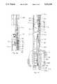
- FIG. 1schematically illustrates a string of tools and partial cutaway for a packer assembly and crossover tool assembly
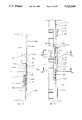
- FIG. 2schematically illustrates in partial longitudinal cross-section a gravel screen assembly
- FIG. 3A and 3Bare illustrative of the tool in a first position after the packer element 32 is initially set to seal off the well bore;
- FIG. 4A and 4Bare illustrative of the tool in position for pumping a gravel slurry to the annulus 62 between the packing means 32 and the lower sump packer SPKR;
- FIG. 5A and 5Bare illustrations of the tool in a position for pumping a gravel slurry to an upper screen assembly
- FIG. 6A and 6Bare illustrations of the tool in a position for reverse circulation of the gravel mixture from the tubing string.
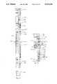
- FIG. 7A and 7Bis an enlarged illustration in partial cross-section through the packer PKR (see FIG. 1);
- FIGS. 8, 9 and 10are enlargement of sections of the packer shown in FIG. 7 and 7B;
- FIG. 11is a view in cross-section taken along line 11--11 of FIG. 10;
- FIG. 12A and 12Bis an illustration of a packer retrieving tool for the packer shown in FIG. 7A and 7B;
- FIG. 13is a view taken along line 13--13 of FIG. 12A;
- FIG. 14A and FIG. 14Bis an illustration of a setting tool for the packer shown in FIG. 7A and 7B;
- FIG. 15is an enlargement view of a section of the tool shown in FIG. 14B;
- FIG. 16is an enlargement view of a section of the tool shown in FIG. 15;
- FIG. 17is a view taken along line 17--17 of FIG. 16;
- FIG. 18is an illustration of the crossover tool assembly
- FIG. 19is a view of a part of the gravel port valve in the screen assembly.
- FIG. 20is an enlarged view of a part of the tool shown in FIG. 18;
- FIG. 21is a view taken along line 21--21 of FIG. 20;
- FIG. 22is a view taken along line 22--22 of FIG. 20;
- FIG. 23is a view of the position indicator and float valve.
- FIG. 24is an enlarged view of the gravel valve of FIG. 20 which illustrates a bypass and safety feature of the present invention.
- the string of toolsincludes a setting tool SET, which is attached to the tubular string of tubing TBS.
- the setting tool SETis releasably coupled to a packer PKR.
- Interconnected lugs or castellated members at 30 on the setting tool SET and the packer PKRreleasable interconnect the setting tool SET and packer PKR and permit co-rotation of the setting tool and the packer when engaged with one another.
- the packer PKRincludes a packing element 32, slip means 34 and a lower release collar 36.
- the lower release collar 36is connected by a tubular member SUB to a tubular outer gravel screen assembly 37 which is schematically shown in FIG. 2.
- the tubular outer gravel screen assembly 37includes a tubular gravel valve GRV having gravel ports 38 which are shown in an open position with respect to internal sliding sleeve valve member 40.
- the gravel valve GRVcan be selectively open or closed by manipulation of the setting tool and provide a surface indication of the valve operation.
- Between the packer PKR and the sub SUBis a downwardly facing internal shoulder C3.
- the packer PKRhas an internal sealing bore 42 located above the shoulder C3.
- a tubular sealing bore sub SBSwith an internal sealing bore 44.
- a downwardly facing internal shoulder C2Spaced downwardly from the shoulder C2 is an internal flange section 46 with a bore 47 which forms a downwardly facing shoulder C1.
- the lowermost screen SCRis attached to a sealing sub SSS which has an internal sealing bore 48 with an internal seal packing.
- a sealing sub SSSwhich has an internal sealing bore 48 with an internal seal packing.
- another screen member SCR-1is located below the perforations in the well casing.
- the setting tool SETis connected by a tubular member (not shown in FIG. 1) extending through the packer PKR to a tubular crossover tool XOV which extends into the tubular outer screen assembly 37 below the packer PKR (See FIG. 2).
- the crossover tool XOVhas longitudinally spaced upper, exterior sealing means 50 along its length and longitudinally spaced lower exterior sealing means 52 along its length.
- the sealing means 50 and 52are located above and below radial crossover ports 56 in the crossover tool XOV.
- the sealing means 50 and 52are adapted to be received in the respective sealing bore 42 of the packer PKR and the bore 44 of the sealing bore sub SBS (see FIG. 2) so that the crossover ports 56 in the crossover tool XOV can communicate with the gravel ports 38 in the gravel valve GRV.
- the indicator collar INDhas resilient arm members 58 which are adapted to be compressed radially inward toward the central axis of the indicator collar in response to compression within a restricted or smaller diameter bores 47,44 and 42 located above each of the shoulders C1, C2 or C3.
- the arm members 58are compressed inwardly in response to a pulling or strain force on the tubing string TBS until a predetermined pulling force value is reached which causes the arm members 58 to be compressed in one of the bores 47, 44 or 42 and to slide through such bore.
- the entry of the arm members 58 into one of the bores 47,44 or 42provides a quick upward movement or release for the tension in the tubing string TBS.
- the upward movementis easily observed and indicates to the surface operator that a position C1, C2 or C3 was located by the indicator collar.
- the reverse actionoccurs when the string of tubing is moved downwardly from the C3 position to the C1 position.
- the operatorcan determine that the tool is functioning properly and can recycle this operation as many times as desired to obtain surface indications of operation and location.
- FIGS. 1 and 2are references to other figures for further details of the particular components and assemblies.
- FIGS. 3-6the schematic drawings are illustrative of the fundamentals of a gravel pack operation utilizing the present invention.
- the setting tool SET, the packer PKR and the crossover tool XOVare partially illustrated in an assembly position after insertion through a well pipe WEP in a well bore and after setting of the packer element 32 of the packer PKR.
- the lower end of the screen assembly 37is slidably and sealingly received in a conventional sump packer SPKR which has previously been set in the well bore.
- the tubular sleeve valve member 40 in the screen assembly 37is located below the gravel ports 38 in the gravel valve while the sealing means 50 engage the seal bore 42 in the packer PKR and sealing means 52 engage the seal bore 44 in the seal bore sub SBS.
- the indicator collar IND on the crossover tool XOVis located below the shoulder C1 on the flange section 46.
- the lower end of the tail pipe TLPis sealingly received in the bore 48 of the sealing sub SSS (FIG 3B) and the tail pipe TLP opens to the bore below the sealing sub SSS to the interior of the screen SCR-1.
- the setting tool SEThas left handed threads 60 in releasable threaded engagement with left handed threads in the bore of the packer PKR. Because of the interconnected fingers at 30, right hand rotation will not release the setting tool from the packer.
- a sealing ball 63is dropped or pumped down to a valve seat 64 and the hydraulic pressure in the tubing string TBS is increased to a second and higher level which is sufficient pressure on the ball to set the packer PKR.
- slip members 61 in the slip means 34are in engagement with the wall of the well pipe WEP and the elastomer packing element 32 is expanded to close off fluid communication in the annulus 62 located between the well packer PKR and the well pipe WEP below the packing element 32.
- the valve seat 64has ports 65 which permit fluid bypass while the tool is run in the well bore.
- the sealing ball 63closes off the ports 65.
- the valve seat 64is shear pinned to the crossover tool XOV and, in the position shown, with the sealing ball 63 closes off crossover ports 58 in the cross over tool XOV.
- the indicator collar INDWhen the threads 60 are released, an upstrain is taken on the string of tubing TBS so that the indicator collar IND can successively engage the shoulders C1, C2 and C3.
- the rig load indicator(not shown) at the earth's surface will provide an indication when a predetermined load is obtained by the indicator collar IND engaging a shoulder.
- the indicator collar INDis designed to collapse or compress when the predetermined load is exceeded so that the indicator collar IND can pass through the smaller bore section located above a shoulder.
- the operatorobserves the rig load indicator responses for each of the interactions of the indicator collar IND with the respective shoulders C1, C2 and C3, then the operator is assured that the setting tool set is released and is movable between three operating positions, C1, C2 and C3. This checking can be repeated.
- the indicator collar INDengages the sleeve valve member 40 on upward movement, the valve member 40 is moved upwardly to close off the gravel valve ports 38 before the collar IND passes through.
- the collar INDOn a downward stroke where the collar IND is above the sleeve member 40, the collar IND will move the valve member 40 down and open the ports 38.
- the valve ports 38are selectively opened and closed. Should the hydraulic release fail to operate, the setting tool can be alternatively released by right hand rotation.
- the tubing string TBSis then lowered so the indicator collar IND again opens the gravel valve ports 38 by sliding the valve sleeve 40 downwardly and the indicator collar IND is returned to a position in engagement with the shoulder C1 (See FIG. 4B).
- the tail pipe TLP on the lower end of the crossover toolis in sealing engagement with the bore 48 of the sealing sub SSS and the setting tool set is disengaged from the packer PKR.
- the setting toolis raised to a reverse position where the hydraulic pressure in the tubing string TBS is increased to a second and higher level which is sufficient pressure on the ball 63 to cause a shear pin (not shown) to shear and to permit the valve seat 64 to move downwardly and thereby open the crossover ports 58 in the crossover tool to the interior of the string of tubing.
- the crossover tool XOV at the location of the radial crossover ports 58has longitudinally extending bypass passages 66 which are located in circumferential locations about a longitudinal axis and are circumferentially spaced at locations between the radial crossover ports 58.
- bypass passages 66extend upwardly into an annular space which has exit ports 80 in the setting tool SET which open to the exterior of the bypass tool XOV.
- exit ports 80communicate with an annulus 73 between the well pipe and the tubing string and which is located above the packing element 32.
- the earth formations 68have eroded and formed a cavity 69 behind the well pipe WEP.
- a liquid and gravel mixture or slurrycan be pumped down under pressure through the bore of the string of tubing TBS (Arrow 71a) to pass through the crossover ports 58 (Arrow 71b) into an annulus 74 between the crossover tool and the well screen assembly.
- the mixturethen passes through the gravel ports 38 (Arrow 71c) into the annulus 62 between the screen assembly and the well bore.
- the mixtureflows downward to the lower end of the annulus 62.
- the bottom end of the screen assembly SCR-1is typically located just above the bottom of the well bore or above a sump packer SPKR (See FIG. 3B) and just below the perforations.
- the tubing string TBSis raised to engage the indicator collar IND with the shoulder C2 (See FIG. 5B).
- the operationcan detect this location at the earth's surface.
- the open end of the tail pipe TLPis located above the bore 48 of the seal sub SSS so that liquid can be returned through the porus screen SCR which is located along the perforations.
- the cavity 69is packed with gravel.
- the passage of the slurry and return of liquid through the toolis otherwise as explained with respect to FIGS. 4A and 4B. This permits packing of gravel in the perforations and the formations adjacent to the screens.
- the tubing string TBSis raised to engage the indicator collar IND with the shoulder C3 as shown in FIG. 6A and 6B.
- the operatorcan detect this location at the earth's surface. In this position, both the crossover ports 58 and the gravel ports 38 are located above the packer element 32. Mud or other control liquid can be pumped down the annulus 73 to reverse the flow of gravel liquid mixture to the ground surface (see Arrows 75) through the tubing string TBS.
- the packer PKR of the present inventionhas circumferentially arranged slip members 61 in a tubular slip cage 89 where the slip members 61 are radially movable for gripping engagement with the wall of a pipe for preventing movement in either direction relative to the pipe.
- the elastomer packing elements 32are radially expandable from a retracted condition to an extended condition to sealingly engage the wall of the pipe and to effectively block or packoff the annulus between the pipe and the well tool.
- the slip members 61 and the packing elements 32are actuatable in response to a longitudinal setting motion of an outer tubular member or setting sleeve 92 relative to an inner tubular member or mandrel 100.
- the relative longitudinal motionfirst actuates the slip members 61 to move from a retracted position to a wall engaging position and then moves the packing elements 32 from a retracted to an expanded wall engaging condition.
- the inner mandrel 100 and outer member 92are locked to one another by a one way ratchet system to maintain the packer in a set position.
- a release system 95(See FIG. 10) is selectively actuatable to release the packing elements 32 and the slip members 61 from the set position and enabling the packing elements and the slip members to return to a retracted condition.
- the construction of the packerincludes the tubular central mandrel 100.
- the tubular mandrel 100includes a member of interconnected elements including a top sub 100a, a central mandrel section 100b, and a segment retainer 100c.
- the upper end of the top sub 100ahas a internal left hand thread 102 which is adapted to cooperate with a left hand threaded device 60 on the setting tool.
- This left handed threaded connectionprovides a secondary release mechanism to release the setting tool from the central mandrel by right-hand rotation.
- the primary release mechanism for the setting tool threadsis hydraulically actuated to release the threaded connection.
- the packer and anchor assemblywhich includes the packing means 32 and the anchoring means 34 are disposed on the central mandrel 100.
- a tubular sub element 116has a threaded end 117 for threaded attachment to the outer gravel screen assembly.
- the upper end of the sub 116is connected to a tubular slip connector sleeve 112.
- the connector sleeve 112is slidably disposed on the segment retainer 100c and extends upwardly to a connection with a lower slip cone 114 (FIG. 7A) located in the slip assembly 34.
- the segment retainer 100c(see also FIGS. 10 and 11) has an internal annular recess or counterbore 119 which slidably and sealingly receives a tubular release sleeve 118.
- the release sleeve 118is releasable coupled to the segment retainer 100c by a shear pin 120.
- the segment retainer 100chas circumferentially located windows or rectangularly shaped openings 122 (See FIG. 10 and 11) which respectively receive solid arcuately shaped lock segments 124.
- the lock segments 124have external screw threaded portions 126 which threadedly engage an internal threaded bore section 128 in the connector sleeve 112.
- the tubular release sleeve 118has an internal bore diameter similar to the diameter of the bore 130 of the mandrel section 100b.
- the lock segments 124are each provided with an internal, horizontal located, release groove 132 to define a spaced apart, upper tab element 132a and lower tab element 132b. In the position of the release sleeve 118 illustrated in FIG.
- annular grooves 118a, 118b in the release sleeve 118which are spaced from one another and which have widths which are sized so that if the release sleeve 118 is shifted upwardly an appropriate distance, the upper and lower end tab elements 132a, 132b of the lock segments 132 will be received in the upper and lower annular grooves 118a, 118b and will release the lock segments 132 for movement inwardly toward the central axis of the tool.
- the lock segments 132move inwardly, the threaded engagements of the threaded portions 126 with the connector sleeve thread 128 are released and thus the slip connector 112 is released from interconnection with the lower segment retainer 100c.
- Upper and lower seal means on the release sleeve 118provide a debris barrier for the release sleeve 118 relative to the lower segment retainer 100c and prevent intrusion of debris.
- a vent port 118ais located between the seals.
- a counterbore 134In the lower end of the release sleeve 118 is a counterbore 134 which defines a downwardly facing latching shoulder 135 and latching recess.
- the latching shoulder 135is engageable by a release tool (to be described hereinafter) for shifting the release sleeve 118 upwardly and for obtaining release of the lock segments 124 to release the connector sleeve 112.
- the slip connector 112is connected to the tubular lower cone member 114 which has an upwardly facing inclined or frusto-conical expander surface 137 which is engageable with expander surfaces on double inclined slip elements 61.
- a number of slip elements 61are circumferentially arranged and located in elongated slots in tubular slip cage 89 which is disposed about the circumference of the tool.
- the slip members 61 at their lower ends,are located within the slip cage 89 and the cone member 114 has radial pins 141 (FIG. 7A) which are longitudinally slidable in longitudinal slots 141a in the slip cage 89. This permits relative longitudinal movement between the lower cone member 114 and the slip elements 61 for moving the slip elements 61 from a retracted position shown to an extended position where the outer serrated edges of the slip elements grip the wall of a pipe.
- the upper cone member 144has a downwardly facing inclined surface which engages each upper internal end of a slip member 61 and similarly the cone member 144 is connected by pins 145 to a longitudinal movement slot 146 in the slip cage 89.
- the upper cone member 144has an internal annular clutch recess 148 (see FIG. 9) which contains a one-way clutch or ratchet member 149.
- the ratchet member 149has internal serrated teeth which engage a serrated outer surface of the mandrel 100b when the cone member 144 moves downwardly. The ratchet member 149 prevents return movement of the upper cone member 144 relative to the central mandrel 100b and thus holds the slips in a set position by preventing the slip 144 form moving upward relative to the mandrel.
- the upper cone member 144is connected by a tubular extension 150 to a lower gauge ring 150a and to a tubular support sleeve 150b.
- the support sleeve 150bis slidably mounted on the mandrel 100b.
- the lower gauge ring 150aforms the bottom support for an end element of an elastomer packing means 32.
- the packing means 32is a three piece packer element construction consisting of a lower element, a center element and an upper element constructed of elastomer material.
- the tubular element support sleeve 150bsupports the inner surface of the elastomer elements and permits the movement of the mandrel relative to the packing elements.
- Above the upper packer elementis an upper gauge ring 156.
- the upper gauge ring 156is connected to a lock ring support 157 (see FIG. 8).
- the lock ring support 157is connected to the support sleeve 150b and to the tubular external setting sleeve 92 which extends upwardly beyond the end of the central mandrel 100a.
- the setting sleeve 92is releasable connected to the mandrel 100a by a shear pin 160.
- the lock ring support 157has an internal annular space 162 with respect to the tubular mandrel 100b, which receives a "C" shaped locking element 164 (See FIG. 8).
- the locking element 164has inner and outer interacting serrated teeth arranged with respect to the lock ring support 157 and an inner gripping serration 166 on the mandrel 100b so that when the mandrel 100b and the lock ring support 157 are moved relative to one another, the teeth provide a one way ratchet locking action.
- the gripping serration 166 on the mandrel 100bextends along the mandrel surface a sufficient distance for one way ratcheting of the locking element 164 when the ring support 157 is moved relative to the central tubular member 100b. It should be appreciated that the pitch on the inner and outer serrated teeth of the locking element 164 are different and such that an upward force on the ring support 157 permits movement upwardly with respect to the mandrel 100b.
- the setting tool(which will be explained hereafter) is releasable attached to the central mandrel 100 by the left-hand thread 102 so that a downward force can be applied to the setting sleeve 92 to move the setting sleeve 92 downwardly with respect to the mandrel 100.
- downward motion of the setting sleeve 158drives the upper gauge ring 156 downwardly and the stiffness of the packing elements 32 does not permit their initial expansion so that the downward motion is imparted to the upper cone member 144 and to the slip elements 61 in the slip cage 89.
- the lower cone element 114is held fixed relative to the tubular mandrel 100 by the lock segments 124 in the segment retainer 100c (See FIGS. 10, 11).
- the lower end of the slip elements 61move up the inclined ramp 137 on the lower expander cone member 114 and extend radially outward until they engage the wall of the well bore whereupon continued force is applied by the upper expander cone member 144 to the upper end of the slip members 61.
- the ratchet member 149prevents return movement of the cone member 144 (See FIG. 9).
- the continued downward force on the setting sleeve 92then expands the packing elements 32 with the support sleeve 150b sliding relative to the upper cone member 114 until the packing elements 32 are in sealing engagement with the wall of the pipe.
- the sliding motionis permitted by a pin 170 and slot 171 coupling.
- the ratchet body lock ring 164retains the ring support 157 in a fixed position with the packing elements 32 expanded and the slip elements 61 expanded into contact with the wall of the well bore.
- the packeris released by use of a packer release tool (to be explained hereafter) where the release tool extends through the central mandrel 100 and has a latch mechanism which engages the downwardly facing shoulder 135 in the release sleeve 118 (See FIG. 10). Upward movement of the packer release tool then applies an upward force sufficient to shear the shear pin 120 so that the annular grooves 118a, 118b in the release sleeve 118 are registered with the end tab portions 132a, 132b of the lock segments 132 releasing the connector sleeve 112 and lower cone member 114.
- the mandrel 100can be moved upwardly until an upwardly facing shoulder 180 (FIG. 7A) on the mandrel 100b engages a downwardly facing shoulder 181 in the upper ring support 157.
- This engagementpermits the upper ring support 157 to be moved upwardly (by ratcheting of the ring 164) thus releasing the force on the packer element and permitting the expander elements 32 to retract.
- the expander elements 32retract until the upward facing shoulder 180 on the support sleeve (150B) engages the downward facing shoulder on the lower gage ring (150A) and pulls the upper cone upwardly.
- the upper cone elementengages a shoulder in the cage element 89 whereupon the cage 89 is pulled upwardly to release the slip elements and the windows in the slip cage pull the slips up which in turn, pulls the slip elements from the lower cone element 114.
- the systemis then released and can be retrieved from the well bore.
- the packer retrieving tool 200includes a tubular top sub 201 adapted to be coupled to a string of tubing.
- the top sub 201is coupled to a tubular upper mandrel 202.
- the upper mandrel 202has a section 202a with a non-circular cross section (See FIG. 13) which is slidably and non-rotatably received in a non circular bore of a tubular latch retainer 204.
- the latch retainer 204has a tubular lower extension 205 which supports a latch ring 207 with collet fingers 209.
- the collet fingers 209are externally threaded with left-hand threads matching the threads 102 in the packer (See FIG. 7).
- the collet fingers 209are keyed by longitudinal key members on the tubular extension 205 so as to co-rotate with rotation of the mandrel 202.
- the mandrel 202is also connected by a sub 213 (FIG. 12B) to a lower mandrel 214 which carries a latching mechanism for operating the release sleeve 118 (FIG. 10).
- the packer releaseprepares the packer for retrieval.
- the latching mechanismincludes a tubular catch sleeve 220 which is biased to a downward position by a spring member 222 disposed between the sub 213 and a ring part 224 on the catch sleeve 220.
- the catch sleeve 220has lower collet type fingers 225 with external latch projections 226 for engaging the latching shoulder 135 (FIG. 10) in the release sleeve 118 of the packer.
- the spring member 222normally biases the catch sleeve fingers 225 into engagement with a cone surface 228 on a mandrel part 230.
- the catch sleeve fingers 225 and ring 224are moved upwardly against the force of the spring member 222 to retract the catch sleeve fingers 225 toward a recess 232 on the lower mandrel 214 and enable passage through the bore of the packer.
- the catch sleeve fingersreach the latching shoulder 135 in the release sleeve in the packer, the catch sleeve fingers spring outwardly into engagement with the latching shoulder 135 and are held outwardly by engagement with the shoulder 135 by subsequent engagement with the cone surface 228.
- a shear pin release 237is used to disable the retrieving tool and permit its retrieval.
- the setting tool assemblyincludes a top sub 300 which is connected to a tubular central mandrel 302.
- the lower end of the central mandrel 302connects to a setting tool mandrel 304 by a tubular coupling 305.
- the lower end of the setting tool mandrel 304is threadedly coupled to a tubular central crossover mandrel 306 (FIG. 14B).
- annular hydraulic pressure chambers 308a and 308bwhich are between the central mandrel 302 and tubular outer housing member 310.
- the housing member 310is coaxially connected to the top sub 300 and the first upper hydraulic chamber 308a is defined between the central mandrel 302 and the inner wall of the outer housing member 310.
- the chamber 308aextends to a lower flange ring 311 on the outer member 310.
- a piston 313, which includes a piston head and tubular extension,is slidably mounted on the central mandrel 302 where the tubular extension 313a is slidable through the lower flange ring 311.
- the piston 313is adapted to be initially positioned in an upper location, as shown in the drawing.
- an access port 315 in the central mandrel 302accesses hydraulic pressure from the interior of the tubing string to one side of the piston head 313b while the other side of the piston head 313b is accessed by a port 317 in the outer member 310 to the pressure in the annulus located exterior to the outer member 310.
- the tubular extension 313ahas a shoulder 320 located along its length which limits the downward travel of the extension 313a relative to the lower flange ring 311.
- chamber 308bwhich similarly has a piston 322 with a tubular extension 322a. Hydraulic pressure of liquid is accessed from the interior of the central mandrel 302 through an access port 326 and the chamber 308b has a port 328 at its lower end to the exterior of the outer member 310.
- a flange ring 329 in the outer member 310slidably receives the tubular extension 322a.
- Another chamber 330is formed between the walls of the central mandrel 302 and the outer member 310 and contains a piston member 332.
- One side of the piston 332is accessed to hydraulic pressure by a port 333 in the central mandrel 302.
- the other side of the piston 332is accessed to the exterior of the tool by an access port 335.
- the piston member 332is threadedly attached to a tubular actuating sleeve 334 (FIG. 14B) which slidably extends over the tubular coupling 305.
- the tubular actuating sleeve 334is also slidably received within the bore 336 of a tubular clutch sleeve 338.
- the clutch sleeve 338is attached to the outer member 310.
- the clutch sleeve 338is provided with circumferentially spaced lug members 345 (lug connection 30 of FIG. 1) at its lower end which are adapted to co-rotatively engage with lug slots 342 in the upper end of the packer actuating sleeve 334 (See FIG. 7A).
- the clutch sleeve 338has guide pins 340 which are located in longitudinal slots 347 in the actuating sleeve 334 to permit sliding but non-rotative relationship between the clutch sleeve 338 and the actuating sleeve 334.
- the setting tool mandrel 304which is attached by a coupling 305 to the lower end of the central mandrel 302 has an upper reduced diameter section 344 (See FIG. 15) forming an upwardly facing shoulder 346.
- a counterbored tubular release sleeve 348is slidably and sealably received on the setting tool mandrel 304.
- An access port 350 in the setting tool mandrel 304opens to a location between seals on the different diametered wall surfaces 344 and 352 on the mandrel 304.
- the differential pressure areapermits pressure in the interior of the setting tool mandrel 304 to act through the port 350 to move the release sleeve 348 upwardly.
- the release sleeve 348is releasable held in its initial condition by a shear pin 354.
- the release sleeve 348also has a one-way ratchet mechanism 356 disposed in a recess for preventing return travel once the release sleeve 348 is moved upwardly. (See FIG. 15).
- a collet finger support sleeve 364has an upwardly extending tubular extension with a outwardly extending flange 366 where the flange 366 is disposed in the intermediate recess 360 so as to provide a spacing or lost motion interconnection of the collet finger support sleeve 364 relative to the release sleeve 348.
- the collet finger support sleeve 364has longitudinal slots 367 circumferentially arranged to receive longitudinal guide lugs 368 on the central mandrel 304.
- the outer surface of the lower end of the collet finger support sleeve 364has a stepped diameter portion forming an upper support surface 376a and a linear support surface 378a.
- a collet finger connector 370includes a ring section and depending collet fingers 372 which are disposed on the support sleeve 364 where the collet fingers 372 have external left handed threads 374 for engagement with the left handed threaded bore 102 of the packer.
- the collet fingers 372have offset inner surfaces 376, 378 to respectively engage the surfaces 376a, 378a on the finger support sleeve 364.
- hydraulic pressureis developed to a first predetermined value in the string of tubing and acts through the access ports 315, 326, 333 on the pistons 313, 322, 332 (See FIG. 14) in the setting tool to move the setting sleeve 334 downwardly while the collet fingers 374 in the threaded bore 102 retain the packer fixed relative to the setting tool mandrel.
- the relative movementproduces a downward motion of the setting tool actuating setting sleeve 334 on the packer and the packer is set and locked in position as described hereabove.
- the lugs 345are disengaged from the packer.
- hydraulic pressure at a higher pressure value than the hydraulic pressure required to set the packeracts through the access bores 350 (See FIGS. 15,16) to shear the pin 354 and actuate the release mechanism for the threaded collet members 374 to release from the packer bore 102.
- the threaded collet members 274are hydraulically released from engagement with the packer.
- the crossover assemblyas shown in FIG. 18 of the drawings includes an upper seal sub 400 which is coupled to the setting tool mandrel 304.
- the lower end of the seal sub 400connects to concentrically arranged tubular inner member 401 and tubular outer member 402.
- the inner member 406has a central bore 404 smaller than the bore 405 of the seal sub 400 to define an upper ball seat 406.
- the seal sub 400has external seal means 407 (Seal 50,52 in FIG. 1) disposed along its length at various location for sealing in the bore of the screen assembly.
- a bypass exit port 408(port 80 in FIG. 4A) which is in fluid communication with an annular bypass passage 409 (annulus 78 in FIG. 5A) located between the inner member 401 and the outer member 402.
- the number of seal means 407 spaced longitudinally along the outer member 402are as necessary to maintain a sealing continuity of the outer member 402 with respect to the seal bores in the screen assembly.
- the lower ends of the inner member 401 and outer member 402are connected to a crossover sub 410.
- the crossover sub 410is tubular with a thick wall.
- Circumferentially spaced axial bypass passages 412extend through the length of the sub 410 (See FIGS. 20-22).
- radial gravel ports 414are intermediate of the bypass passages 412 which extend from the central bore 415 of the sub 410 to the exterior wall 416 of the sub.
- the crossover sub 410is connected to a tubular lower outer member 421 (FIG. 20 and 21).
- the outer member 421has seal means 407 disposed along its length which cooperate with the lower seal bore in the screen assembly for maintaining sealing continuity of the tool.
- An inner tubular member 423has radial outwardly extended lugs 424 (See FIG. 22) which engage with an annular recess 425 in the outer member 421.
- An inner annular ring member 426 on the tubular member 423defines an upwardly facing stop shoulder 427 above a smaller diameter bore 430 of the inner member 423.
- the gravel port valve 435(member 64 in FIG. 3A) is slidably received in the bore 430 of the inner member 423 and has flange 442 to limit downward travel to engagement with the stop shoulder 427.
- the valve 435has a solid cross section located below an upper tubular section with radial ports 432 (ports 65 in FIG. 3A) where the ports align with the gravel ports 414 (ports 58 in FIG. 3A) in the crossover sub 416.
- the upper end of the tubular sectionforms a ball seat 440.
- a set of shear pins 450retain the valve 435 in an open position.
- FIG. 24An important feature of the present invention is illustrated in the enlarged illustration in FIG. 24. To best understand this feature, it will be remembered that when the tool is made up at the earth's surface the volume below the seal 460 in the valve 435 is at atmospheric pressure. In going in the hole, liquid under hydrostatic pressure is admitted to the atmospheric volume below the seal 460 through the float valve FLV (see FIG. 3A). The volume below the seal 460 is sealed above the exit ports 80 (FIG. 3A) by a seal 80A.
- there has been no method or system to relieve the hydrostatic pressure in the toolshould the tool be retrieved without setting the packer. As a result a high pressure chamber condition can exist if a tool is retrieved and can cause damage and injury at the earth's surface.
- the crossover sub 410is provided with a counterbore 450 which does not engage the seal 452 on the valve 435 so that there is a bypass passage 454 to the ports 414.
- a counterbore 450which does not engage the seal 452 on the valve 435 so that there is a bypass passage 454 to the ports 414.
- a ball member 63is seated on the seat 440 at an appropriate time to permit hydraulic actuation of the packer. Thereafter, a first higher pressure can be used to shear the pins 450 and permit downward movement of the plug member 435 relative to the inner member 423.
- a first higher pressurecan be used to shear the pins 450 and permit downward movement of the plug member 435 relative to the inner member 423.
- the valve 435moves downwardly until the upper end of a slot 456 engages a set of shear pins 451.
- the shear pins 451are sized to require a greater pressure than the setting pressure required to set the packer.
- the seal 452enters the bore 462 and traps hydrostatic pressure below the valve 435 while the packer is being set.
- valve 435To open the valve 435, additional pressure is supplied to shear the pins 451 and move the ball valve seat 440 below the gravel ports.
- the lower end of the outer member of the crossover toolis coupled to a conventional float valve 500 (See FIG. 23).
- the float valve 500is conventional in design and includes a spring biased valve member 501 which engages an upwardly facing valve seat 502.
- the valvehas bypass ports 504 and permits fluid flow upwardly but not downwardly.
- the float valve 500is connected to a tubular indicator body 505 which has an upper flange 506 and a lower flange 507 and a central outer recess 508.
- a tubular collet indicator INDis formed from a tubular member 509 with longitudinally extending slots 510 and centrally located external flanges 512.
- the flanges 512are, in effect, centrally located on flexible metal beams where the beams can be resiliently compressed upon entering a smaller bore diameter and resume their original configuration upon entering a larger bore diameter from a smaller bore section.
- the lower end of the body 505has a tail pipe sub 512 which couples to a polished tail pipe (not shown in FIG. 23) which is slidably and sealingly receivable in a seal sub.
- the gravel valve GRVincludes interconnected pipe sections 600, 601 and 602 in the sub SUB.
- An internal annular recess 605is formed between facing stop shoulders 606 and 607.
- a tubular slide valve member 610(valve 40 in FIG. 2) is slidably mounted in the recess 605 and shown in an open position where the gravel ports 38 communicate the interior bore to the exterior of the tool while the valve member 610 is in a lower position and engages the stop shoulder 607.
- the valve member 610has an upper tubular section 610a with spaced apart seals 611 which straddle the ports 38 where the valve member is in an upper position.
- windowed tubular member 610bwhich has collet type fingers 615 biased resiliently inwardly to define a bore diameter 616 less than the O.D. diameter of the flanges on the indicator IND.
- the collet fingers 615are attached to a ring base 617 which has an internal shoulder 618 with a bore diameter less than the O.D. diameter of the flanges on the indicator IND.
- the indicator INDWhen the indicator IND is moved upwardly from a location below the valve member 610, it engages the shoulder 616 and moves the valve member 610 upwardly into engagement with the stop shoulder 606. At this time the fingers 615 are disposed adjacent to an annular recess 620 in the pipe section 601 and latch into the recess 620 and enlarge the diameter of the bore for the fingers. Thus, when the indicator IND is moved upwardly it engages the shoulder 616 to move the valve member 610 to an open position.
- the systemincludes a hydraulic set packer with tubular gravel screen extensions and a hydraulic setting and crossover tool. It should be appreciated that the packer and screen assembly can be run in and set with a wireline tool with the crossover tool subsequently run in on a string of tubing.
- the system as discussed aboveis designed to perform a gravel pack operation with a single trip of the string of tubing.
- the position indicator INDmakes the system ideal for deep and deviated/horizontal wells in that the operator can determine the setting release and the movement required for the tool operations from surface indications.
- the tool operationsare repeatable (as contrasted to one-shot) so that the operation can be repeatedly confirmed. No rotation is required to operate the tool; all operations are achieved through pressure and vertical movement. Rotation, however, can be safely used during transmission of the tool to the downhole location.
- the systemhas a backup for each of the operations of the service tool in the event a primary function should fail.
- the hydraulic set packer PKR and gravel screens SCRare run into the hole with the attached setting tool set and crossover tool XOV to the location depth.
- the bore of the tool and the gravel packer portsare open to bypass fluid while going in the hole.
- the sealing ball 63is dropped when the packer reaches the proper depth and seats on the valve seat 64.
- the packeris then hydraulically set. The packer and tubing are then tested for leaks.
- the setting toolis then operated by use of a higher second tubing pressure which hydraulically releases the setting tool from the packer (See FIG. 16).
- the gravel pack slurryis then pumped down the tubing string and crossed over to the screen/casing annulus below the setting tool.
- the gravelis packed into the annulus and perforated well bore.
- the excess gravelis reversed out and the setting tool retrieved leaving the packer in the hole as a retrievable production packer.
- a convention seal assembly(not shown) is run on a production tubing seals in the packer bore to complete the well.
- the packercan be retrieved from the well bore by means of a retrieving tool.
- Rotationis available as a backup system release mechanism.
- the setting tool and crossover toolare not sensitive to low bottom hole pressures and a check valve assembly 500 (FIG. 23) is run below the ball seat 440.
- the setting toolhas a dual operated sealing ball valve.
- the primary systemis to shift the sealing ball valve by applying tubing pressure. If this is not possible due to debris or tubing pressure ratings, the seating ball seat can be shifted by applying annulus pressure. This is accomplished by applying annulus pressure which will act upon the ball.
- the setting tool and crossover toolare positioned by vertical tubing string movements. There are four positions; a squeeze position (FIG. 3A and 3B) where fluid is not returned to the surface, a lower circulation position (FIG. 4A and 4B) where fluid is returned through a lower screen only and an upper circulation position (FIG. 5A and 5B) where fluid returns through the main screens, and a reverse circulation position (FIG. 6A and 6B) where fluid flows from the annulus to the tubing string.
- the indicator collar INDprovides a positive weight indicator position of the crossover tool in the upper, lower and reverse circulating positions.
- the setting toolis mechanically interlocked to allow right-hand torque and rotation of the packer while going in the hole. The tool cannot accidentally be backed off of the packer.
- the mechanical interlockis disengaged during packer setting.
- the assemblyis initially set up by installing the setting tool and crossover assembly into the gravel pack packer with the left-hand thread 374 on the setting tool threadedly engaged with the matching thread 102 on the top sub 100a of the packer PKR.
- the screens SCR, SCR-1 and blank pipeare added to the assembly at the rig site. While running in the hole, fluid in the well bore is bypassed by the tubing string through the ports 38,56.
- an appropriate sealing ball 63is dropped down the tubing and it lands on the ball seat 440 in the crossover valve (FIG. 20) providing a seal when pressure is applied to the string of tubing.
- the pistons 313, 323, and 332 in the setting toolproduce a relative movement between the mandrel 100 of the packer and the actuating sleeve 158.
- the actuating sleeve 334 of the setting toolmoves the actuating sleeve 158 of the packer.
- the load on the actuating sleeve 158increases until the shear screws 150 connecting the actuating sleeve 158 and the top sub 100a shear. This action allows the outside tubular assembly of the packer assembly to be shifted relative to the mandrel 100.
- the packer body lock ring 164begins ratcheting down the mandrel 100b.
- the body lock ring 161maintains/captures any downward displacement between the upper portion of the packer exterior and the mandrel.
- the top of the upper slip cone 144engages the slip elements 61 which are held in a retracted position by slip springs.
- the steep angle on the nose of the upper slip cone 144forces all of the slips to become aligned and start moving up the ramp surface 137 of the lower slip cone 114 together.
- the upper cone 144continues down until the slip element 61 engage the casing.
- the load on the actuating sleeve 158increases forcing the wickers of the slip elements to penetrate the wall of the casing and to apply a compressive load on the rubber elements 32.
- the loadincreases, the length of the rubber elements 32 decreases and their diameter increases. This movement continues until the rubber elements 32 are tightly pressed against the wall of the casing.
- a backup systemis provided.
- a second ball(not shown) with a large diameter is dropped down the tubing and comes to rest on the secondary ball seat 406. These parts provide a backup seal for tubing setting pressure for the packer and release of the setting tool.
- the XOV Toolis attached to setting tool and all is accomplished in one trip.
- the setting toolis released from the packer.
- the primary method of releaseis with tubing pressure.
- the secondary methodis to mechanically rotate out of the packer.
- the primary releaseis by applying pressure to the tubing so that the hydraulic release piston 348 (FIG. 15) is energized and loads the shear screws 354. When the tubing pressure reaches a predetermined value the shear screws 354 are sheared and allow the release piston 348 to move upwardly. As the release piston 348 moves upwardly it engages the support sleeve 364. As the release piston 348 continues to move upward it pulls the support sleeve 364 out from under the collet fingers 372 and releases the setting tool from the packer.
- the secondary releaseis to mechanically rotate out of the packer.
- the tubing string tensionis adjusted to a neutral point and right-hand torque is applied to the string of tubing to unscrew the left-hand lead thread which connects the collet fingers 372 packer top sub 100b. Approximately ten turns at the packer are required to release the setting tool from the packer.
Landscapes
- Geology (AREA)
- Life Sciences & Earth Sciences (AREA)
- Engineering & Computer Science (AREA)
- Mining & Mineral Resources (AREA)
- Environmental & Geological Engineering (AREA)
- Fluid Mechanics (AREA)
- Physics & Mathematics (AREA)
- General Life Sciences & Earth Sciences (AREA)
- Geochemistry & Mineralogy (AREA)
- Earth Drilling (AREA)
- Excavating Of Shafts Or Tunnels (AREA)
- Revetment (AREA)
- Extraction Or Liquid Replacement (AREA)
Abstract
Description
Claims (33)
Priority Applications (9)
| Application Number | Priority Date | Filing Date | Title |
|---|---|---|---|
| US07/925,173US5332038A (en) | 1992-08-06 | 1992-08-06 | Gravel packing system |
| AU47968/93AAU663274B2 (en) | 1992-08-06 | 1993-07-29 | Gravel packing system |
| DE4393821TDE4393821T1 (en) | 1992-08-06 | 1993-07-29 | Gravel packing system |
| PCT/US1993/007227WO1994003704A1 (en) | 1992-08-06 | 1993-07-29 | Gravel packing system |
| CA002120484ACA2120484C (en) | 1992-08-06 | 1993-07-29 | Gravel packing system |
| NL939320005ANL9320005A (en) | 1992-08-06 | 1993-07-29 | System for applying a gravel jacket. |
| GB9406403AGB2275707B (en) | 1992-08-06 | 1993-07-29 | Gravel packing system |
| NO941217ANO308808B1 (en) | 1992-08-06 | 1994-04-05 | Method and apparatus for determining the operation of a gasket and a connected gravel packing silver tool |
| DK037794ADK37794A (en) | 1992-08-06 | 1994-04-05 | Gravel packing system for use in wellbores |
Applications Claiming Priority (1)
| Application Number | Priority Date | Filing Date | Title |
|---|---|---|---|
| US07/925,173US5332038A (en) | 1992-08-06 | 1992-08-06 | Gravel packing system |
Publications (1)
| Publication Number | Publication Date |
|---|---|
| US5332038Atrue US5332038A (en) | 1994-07-26 |
Family
ID=25451326
Family Applications (1)
| Application Number | Title | Priority Date | Filing Date |
|---|---|---|---|
| US07/925,173Expired - LifetimeUS5332038A (en) | 1992-08-06 | 1992-08-06 | Gravel packing system |
Country Status (9)
| Country | Link |
|---|---|
| US (1) | US5332038A (en) |
| AU (1) | AU663274B2 (en) |
| CA (1) | CA2120484C (en) |
| DE (1) | DE4393821T1 (en) |
| DK (1) | DK37794A (en) |
| GB (1) | GB2275707B (en) |
| NL (1) | NL9320005A (en) |
| NO (1) | NO308808B1 (en) |
| WO (1) | WO1994003704A1 (en) |
Cited By (123)
| Publication number | Priority date | Publication date | Assignee | Title |
|---|---|---|---|---|
| US5425423A (en)* | 1994-03-22 | 1995-06-20 | Bestline Liner Systems | Well completion tool and process |
| US5433275A (en)* | 1994-07-19 | 1995-07-18 | Baker Hughes Incorporated | Double-threaded anchor tubing assembly |
| US5497840A (en)* | 1994-11-15 | 1996-03-12 | Bestline Liner Systems | Process for completing a well |
| WO1996021082A1 (en)* | 1995-01-05 | 1996-07-11 | Osca, Inc. | Improved isolation system and gravel pack assembly and uses thereof |
| WO1996025582A3 (en)* | 1995-02-14 | 1996-10-17 | Baker Hughes Inc | One trip cement and gravel pack system |
| US5577559A (en)* | 1995-03-10 | 1996-11-26 | Baker Hughes Incorporated | High-rate multizone gravel pack system |
| US5676208A (en)* | 1996-01-11 | 1997-10-14 | Halliburton Company | Apparatus and methods of preventing screen collapse in gravel packing operations |
| US5722490A (en)* | 1995-12-20 | 1998-03-03 | Ely And Associates, Inc. | Method of completing and hydraulic fracturing of a well |
| US5823254A (en)* | 1996-05-02 | 1998-10-20 | Bestline Liner Systems, Inc. | Well completion tool |
| US5924487A (en)* | 1997-01-31 | 1999-07-20 | Halliburton Energy Services, Inc. | Proppant slurry screen apparatus and methods of using same |
| US5971070A (en)* | 1997-08-27 | 1999-10-26 | Halliburton Energy Services, Inc. | Apparatus for completing a subterranean well and associated methods |
| US5975205A (en)* | 1997-09-30 | 1999-11-02 | Carisella; James V. | Gravel pack apparatus and method |
| US6142226A (en)* | 1998-09-08 | 2000-11-07 | Halliburton Energy Services, Inc. | Hydraulic setting tool |
| US6176307B1 (en) | 1999-02-08 | 2001-01-23 | Union Oil Company Of California | Tubing-conveyed gravel packing tool and method |
| WO2001011186A1 (en)* | 1999-08-09 | 2001-02-15 | Schlumberger Technology Corporation | Thru-tubing sand control method and apparatus |
| US6220353B1 (en)* | 1999-04-30 | 2001-04-24 | Schlumberger Technology Corporation | Full bore set down tool assembly for gravel packing a well |
| WO2001060545A1 (en)* | 2000-02-18 | 2001-08-23 | Shell Oil Company | Expanding a tubular member |
| US20010047866A1 (en)* | 1998-12-07 | 2001-12-06 | Cook Robert Lance | Wellbore casing |
| US6364017B1 (en) | 1999-02-23 | 2002-04-02 | Bj Services Company | Single trip perforate and gravel pack system |
| US6378609B1 (en)* | 1999-03-30 | 2002-04-30 | Halliburton Energy Services, Inc. | Universal washdown system for gravel packing and fracturing |
| US6446729B1 (en) | 1999-10-18 | 2002-09-10 | Schlumberger Technology Corporation | Sand control method and apparatus |
| US6491108B1 (en)* | 2000-06-30 | 2002-12-10 | Bj Services Company | Drillable bridge plug |
| US6494256B1 (en)* | 2001-08-03 | 2002-12-17 | Schlumberger Technology Corporation | Apparatus and method for zonal isolation |
| US6557640B1 (en) | 1998-12-07 | 2003-05-06 | Shell Oil Company | Lubrication and self-cleaning system for expansion mandrel |
| US6568471B1 (en) | 1999-02-26 | 2003-05-27 | Shell Oil Company | Liner hanger |
| US6571875B2 (en)* | 2000-02-17 | 2003-06-03 | Schlumberger Technology Corporation | Circulation tool for use in gravel packing of wellbores |
| US6575246B2 (en) | 1999-04-30 | 2003-06-10 | Schlumberger Technology Corporation | Method and apparatus for gravel packing with a pressure maintenance tool |
| US6575240B1 (en) | 1998-12-07 | 2003-06-10 | Shell Oil Company | System and method for driving pipe |
| US6575250B1 (en) | 1999-11-15 | 2003-06-10 | Shell Oil Company | Expanding a tubular element in a wellbore |
| US6581681B1 (en)* | 2000-06-21 | 2003-06-24 | Weatherford/Lamb, Inc. | Bridge plug for use in a wellbore |
| US20030132008A1 (en)* | 2001-12-12 | 2003-07-17 | Hirth David E. | Bi-directionally boosting and internal pressure trapping packing element system |
| US6612372B1 (en) | 2000-10-31 | 2003-09-02 | Weatherford/Lamb, Inc. | Two-stage downhole packer |
| US6634431B2 (en) | 1998-11-16 | 2003-10-21 | Robert Lance Cook | Isolation of subterranean zones |
| US6640903B1 (en) | 1998-12-07 | 2003-11-04 | Shell Oil Company | Forming a wellbore casing while simultaneously drilling a wellbore |
| US20040045723A1 (en)* | 2000-06-30 | 2004-03-11 | Bj Services Company | Drillable bridge plug |
| US6712154B2 (en) | 1998-11-16 | 2004-03-30 | Enventure Global Technology | Isolation of subterranean zones |
| US20040069502A1 (en)* | 2002-10-09 | 2004-04-15 | Luke Mike A. | High expansion packer |
| US6725919B2 (en) | 1998-12-07 | 2004-04-27 | Shell Oil Company | Forming a wellbore casing while simultaneously drilling a wellbore |
| US6745845B2 (en) | 1998-11-16 | 2004-06-08 | Shell Oil Company | Isolation of subterranean zones |
| US20040112608A1 (en)* | 2002-12-17 | 2004-06-17 | Jackson Stephen L. | Choke valve assembly for downhole flow control |
| US6769491B2 (en) | 2002-06-07 | 2004-08-03 | Weatherford/Lamb, Inc. | Anchoring and sealing system for a downhole tool |
| US20040149435A1 (en)* | 2003-02-05 | 2004-08-05 | Henderson William D. | Well screen assembly and system with controllable variable flow area and method of using same for oil well fluid production |
| US6789623B2 (en)* | 1998-07-22 | 2004-09-14 | Baker Hughes Incorporated | Method and apparatus for open hole gravel packing |
| US6823937B1 (en) | 1998-12-07 | 2004-11-30 | Shell Oil Company | Wellhead |
| US6892819B2 (en) | 1998-12-07 | 2005-05-17 | Shell Oil Company | Forming a wellbore casing while simultaneously drilling a wellbore |
| US6968618B2 (en) | 1999-04-26 | 2005-11-29 | Shell Oil Company | Expandable connector |
| US20050274513A1 (en)* | 2004-06-15 | 2005-12-15 | Schultz Roger L | System and method for determining downhole conditions |
| US6976541B2 (en) | 2000-09-18 | 2005-12-20 | Shell Oil Company | Liner hanger with sliding sleeve valve |
| US7011161B2 (en) | 1998-12-07 | 2006-03-14 | Shell Oil Company | Structural support |
| WO2006036271A1 (en)* | 2004-09-22 | 2006-04-06 | Halliburton Energy Servcies, Inc. | Sand control completion having smart well capability and method for use of same |
| US7048067B1 (en) | 1999-11-01 | 2006-05-23 | Shell Oil Company | Wellbore casing repair |
| US7055608B2 (en) | 1999-03-11 | 2006-06-06 | Shell Oil Company | Forming a wellbore casing while simultaneously drilling a wellbore |
| US7100685B2 (en) | 2000-10-02 | 2006-09-05 | Enventure Global Technology | Mono-diameter wellbore casing |
| US7100684B2 (en) | 2000-07-28 | 2006-09-05 | Enventure Global Technology | Liner hanger with standoffs |
| US7121352B2 (en) | 1998-11-16 | 2006-10-17 | Enventure Global Technology | Isolation of subterranean zones |
| US20060260795A1 (en)* | 2004-12-03 | 2006-11-23 | Mario Rescia | Stop-sand liner hanger assembly for water wells |
| US7163066B2 (en) | 2004-05-07 | 2007-01-16 | Bj Services Company | Gravity valve for a downhole tool |
| US7168499B2 (en) | 1998-11-16 | 2007-01-30 | Shell Oil Company | Radial expansion of tubular members |
| US7168496B2 (en) | 2001-07-06 | 2007-01-30 | Eventure Global Technology | Liner hanger |
| US7172024B2 (en) | 2000-10-02 | 2007-02-06 | Shell Oil Company | Mono-diameter wellbore casing |
| US7195064B2 (en) | 1998-12-07 | 2007-03-27 | Enventure Global Technology | Mono-diameter wellbore casing |
| US20070102165A1 (en)* | 2005-11-10 | 2007-05-10 | Bj Services Company | Self centralizing non-rotational slip and cone system for downhole tools |
| US20070119600A1 (en)* | 2000-06-30 | 2007-05-31 | Gabriel Slup | Drillable bridge plug |
| US7231985B2 (en) | 1998-11-16 | 2007-06-19 | Shell Oil Company | Radial expansion of tubular members |
| US7234531B2 (en) | 1999-12-03 | 2007-06-26 | Enventure Global Technology, Llc | Mono-diameter wellbore casing |
| US7258168B2 (en) | 2001-07-27 | 2007-08-21 | Enventure Global Technology L.L.C. | Liner hanger with slip joint sealing members and method of use |
| US7274984B2 (en) | 2004-06-14 | 2007-09-25 | General Motors Corporation | Vehicle stability enhancement system |
| US7290616B2 (en) | 2001-07-06 | 2007-11-06 | Enventure Global Technology, L.L.C. | Liner hanger |
| US7290605B2 (en) | 2001-12-27 | 2007-11-06 | Enventure Global Technology | Seal receptacle using expandable liner hanger |
| US7308755B2 (en) | 2003-06-13 | 2007-12-18 | Shell Oil Company | Apparatus for forming a mono-diameter wellbore casing |
| US7325602B2 (en) | 2000-10-02 | 2008-02-05 | Shell Oil Company | Method and apparatus for forming a mono-diameter wellbore casing |
| US7350564B2 (en) | 1998-12-07 | 2008-04-01 | Enventure Global Technology, L.L.C. | Mono-diameter wellbore casing |
| US7350563B2 (en) | 1999-07-09 | 2008-04-01 | Enventure Global Technology, L.L.C. | System for lining a wellbore casing |
| US7360591B2 (en) | 2002-05-29 | 2008-04-22 | Enventure Global Technology, Llc | System for radially expanding a tubular member |
| US7363984B2 (en) | 1998-12-07 | 2008-04-29 | Enventure Global Technology, Llc | System for radially expanding a tubular member |
| US7377326B2 (en) | 2002-08-23 | 2008-05-27 | Enventure Global Technology, L.L.C. | Magnetic impulse applied sleeve method of forming a wellbore casing |
| US7383889B2 (en) | 2001-11-12 | 2008-06-10 | Enventure Global Technology, Llc | Mono diameter wellbore casing |
| US7398832B2 (en) | 2002-06-10 | 2008-07-15 | Enventure Global Technology, Llc | Mono-diameter wellbore casing |
| US7404444B2 (en) | 2002-09-20 | 2008-07-29 | Enventure Global Technology | Protective sleeve for expandable tubulars |
| US7410000B2 (en) | 2001-01-17 | 2008-08-12 | Enventure Global Technology, Llc. | Mono-diameter wellbore casing |
| US7416027B2 (en) | 2001-09-07 | 2008-08-26 | Enventure Global Technology, Llc | Adjustable expansion cone assembly |
| US7424918B2 (en) | 2002-08-23 | 2008-09-16 | Enventure Global Technology, L.L.C. | Interposed joint sealing layer method of forming a wellbore casing |
| US7438133B2 (en) | 2003-02-26 | 2008-10-21 | Enventure Global Technology, Llc | Apparatus and method for radially expanding and plastically deforming a tubular member |
| US20080308282A1 (en)* | 2007-06-13 | 2008-12-18 | Halliburton Energy Services, Inc. | Hydraulic coiled tubing retrievable bridge plug |
| US7503393B2 (en) | 2003-01-27 | 2009-03-17 | Enventure Global Technology, Inc. | Lubrication system for radially expanding tubular members |
| US7513313B2 (en) | 2002-09-20 | 2009-04-07 | Enventure Global Technology, Llc | Bottom plug for forming a mono diameter wellbore casing |
| US7516790B2 (en) | 1999-12-03 | 2009-04-14 | Enventure Global Technology, Llc | Mono-diameter wellbore casing |
| US7552776B2 (en) | 1998-12-07 | 2009-06-30 | Enventure Global Technology, Llc | Anchor hangers |
| US7571774B2 (en) | 2002-09-20 | 2009-08-11 | Eventure Global Technology | Self-lubricating expansion mandrel for expandable tubular |
| US20090223675A1 (en)* | 2008-03-05 | 2009-09-10 | Schlumberger Technology Corporation | Integrated hydraulic setting and hydrostatic setting mechanism |
| US7603758B2 (en) | 1998-12-07 | 2009-10-20 | Shell Oil Company | Method of coupling a tubular member |
| US20090301708A1 (en)* | 2008-06-10 | 2009-12-10 | Savoy Mark J | Parallel fracturing system for wellbores |
| US7712522B2 (en) | 2003-09-05 | 2010-05-11 | Enventure Global Technology, Llc | Expansion cone and system |
| US7739917B2 (en) | 2002-09-20 | 2010-06-22 | Enventure Global Technology, Llc | Pipe formability evaluation for expandable tubulars |
| US7740076B2 (en) | 2002-04-12 | 2010-06-22 | Enventure Global Technology, L.L.C. | Protective sleeve for threaded connections for expandable liner hanger |
| US7775290B2 (en) | 2003-04-17 | 2010-08-17 | Enventure Global Technology, Llc | Apparatus for radially expanding and plastically deforming a tubular member |
| US7793721B2 (en) | 2003-03-11 | 2010-09-14 | Eventure Global Technology, Llc | Apparatus for radially expanding and plastically deforming a tubular member |
| US7819185B2 (en) | 2004-08-13 | 2010-10-26 | Enventure Global Technology, Llc | Expandable tubular |
| US7886831B2 (en) | 2003-01-22 | 2011-02-15 | Enventure Global Technology, L.L.C. | Apparatus for radially expanding and plastically deforming a tubular member |
| US7918284B2 (en) | 2002-04-15 | 2011-04-05 | Enventure Global Technology, L.L.C. | Protective sleeve for threaded connections for expandable liner hanger |
| WO2011093902A1 (en)* | 2010-02-01 | 2011-08-04 | Halliburton Energy Services, Inc. | Method and apparatus for sealing an annulus of a wellbore |
| WO2005049954A3 (en)* | 2003-11-17 | 2011-08-25 | Baker Hughes Incorporated | Gravel pack crossover tool with single position multi-function capability |
| US8297358B2 (en) | 2010-07-16 | 2012-10-30 | Baker Hughes Incorporated | Auto-production frac tool |
| CN103216203A (en)* | 2013-04-22 | 2013-07-24 | 中国海洋石油总公司 | Top conversion tool used for preventing sand |
| US20140034336A1 (en)* | 2012-07-31 | 2014-02-06 | Schlumberger Technology Corporation | Methods and Systems for Treating a Wellbore |
| US8783348B2 (en) | 2010-12-29 | 2014-07-22 | Baker Hughes Incorporated | Secondary flow path module, gravel packing system including the same, and method of assembly thereof |
| US8844627B2 (en) | 2000-08-03 | 2014-09-30 | Schlumberger Technology Corporation | Intelligent well system and method |
| US8869898B2 (en) | 2011-05-17 | 2014-10-28 | Baker Hughes Incorporated | System and method for pinpoint fracturing initiation using acids in open hole wellbores |
| US9157300B2 (en) | 2011-01-19 | 2015-10-13 | Baker Hughes Incorporated | System and method for controlling formation fluid particulates |
| US9200502B2 (en) | 2011-06-22 | 2015-12-01 | Schlumberger Technology Corporation | Well-based fluid communication control assembly |
| US9303501B2 (en) | 2001-11-19 | 2016-04-05 | Packers Plus Energy Services Inc. | Method and apparatus for wellbore fluid treatment |
| US9404337B1 (en) | 2012-02-22 | 2016-08-02 | McClinton Energy Group, LLC | Caged ball fractionation plug |
| EP2184436A3 (en)* | 2008-11-11 | 2017-04-12 | Swelltec Limited | Wellbore apparatus and method |
| US10030474B2 (en) | 2008-04-29 | 2018-07-24 | Packers Plus Energy Services Inc. | Downhole sub with hydraulically actuable sleeve valve |
| US10041332B2 (en) | 2014-01-13 | 2018-08-07 | Halliburton Energy Services, Inc. | Dual isolation well assembly |
| US10053957B2 (en) | 2002-08-21 | 2018-08-21 | Packers Plus Energy Services Inc. | Method and apparatus for wellbore fluid treatment |
| US10267121B2 (en) | 2009-01-22 | 2019-04-23 | Weatherford Technology Holdings, Llc | Expandable slip system |
| US10465462B2 (en) | 2014-10-24 | 2019-11-05 | Magnum Oil Tools International, Ltd. | Electrically powered setting tool and perforating gun |
| US11118432B2 (en)* | 2017-06-19 | 2021-09-14 | Halliburton Energy Services, Inc. | Well apparatus with remotely activated flow control device |
| WO2022026568A1 (en)* | 2020-07-28 | 2022-02-03 | Baker Hughes Oilfield Operations Llc | Slurry outlet with seal protection system |
| US20230056868A1 (en)* | 2021-08-17 | 2023-02-23 | Weatherford Technology Holdings, Llc | Liner deployment tool |
| US20250137337A1 (en)* | 2023-10-31 | 2025-05-01 | Frank's International, Llc | Shearable lock mechanism for storm packer anchor |
| US12442263B2 (en)* | 2023-09-29 | 2025-10-14 | Weatherford Technology Holdings, Llc | Liner deployment tool |
Families Citing this family (6)
| Publication number | Priority date | Publication date | Assignee | Title |
|---|---|---|---|---|
| US5577733A (en)* | 1994-04-08 | 1996-11-26 | Downing; Dennis L. | Targeting system |
| US5636691A (en)* | 1995-09-18 | 1997-06-10 | Halliburton Energy Services, Inc. | Abrasive slurry delivery apparatus and methods of using same |
| US6491097B1 (en) | 2000-12-14 | 2002-12-10 | Halliburton Energy Services, Inc. | Abrasive slurry delivery apparatus and methods of using same |
| DE102004024573B4 (en)* | 2004-05-18 | 2006-06-01 | Daimlerchrysler Ag | Processing cylinder bores for cylindrical crankcase of internal combustion (IC) engine, involves treating cylinder bearing surface of cylinder bore using e.g. electric induction, according to distortion produced during shaping of bore |
| GB201018334D0 (en)* | 2010-11-01 | 2010-12-15 | Extreme Invent As | Expandable packer |
| EP2914798B1 (en) | 2012-10-30 | 2018-09-05 | Halliburton Energy Services, Inc. | Borehole selector assembly |
Citations (9)
| Publication number | Priority date | Publication date | Assignee | Title |
|---|---|---|---|---|
| US3710862A (en)* | 1971-06-07 | 1973-01-16 | Otis Eng Corp | Method and apparatus for treating and preparing wells for production |
| US4372384A (en)* | 1980-09-19 | 1983-02-08 | Geo Vann, Inc. | Well completion method and apparatus |
| US4401158A (en)* | 1980-07-21 | 1983-08-30 | Baker International Corporation | One trip multi-zone gravel packing apparatus |
| US4660637A (en)* | 1985-09-11 | 1987-04-28 | Dowell Schlumberger Incorporated | Packer and service tool assembly |
| US4796707A (en)* | 1986-06-23 | 1989-01-10 | Baker Hughes Incorporated | Apparatus for setting, unsetting, and retrieving a packer or bridge plug from a subterranean well |
| US4842057A (en)* | 1988-06-29 | 1989-06-27 | Halliburton Company | Retrievable gravel packer and retrieving tool |
| US4858690A (en)* | 1988-07-27 | 1989-08-22 | Completion Services, Inc. | Upward movement only actuated gravel pack system |
| US4862957A (en)* | 1985-09-11 | 1989-09-05 | Dowell Schlumberger Incorporated | Packer and service tool assembly |
| US4951750A (en)* | 1989-10-05 | 1990-08-28 | Baker Hughes Incorporated | Method and apparatus for single trip injection of fluid for well treatment and for gravel packing thereafter |
Family Cites Families (7)
| Publication number | Priority date | Publication date | Assignee | Title |
|---|---|---|---|---|
| US4049055A (en)* | 1971-04-30 | 1977-09-20 | Brown Oil Tools, Inc. | Gravel pack method, retrievable well packer and gravel pack apparatus |
| US3726343A (en)* | 1971-06-24 | 1973-04-10 | P Davis | Apparatus and method for running a well screen and packer and gravel packing around the well screen |
| US3987854A (en)* | 1972-02-17 | 1976-10-26 | Baker Oil Tools, Inc. | Gravel packing apparatus and method |
| US4856591A (en)* | 1988-03-23 | 1989-08-15 | Baker Hughes Incorporated | Method and apparatus for completing a non-vertical portion of a subterranean well bore |
| US4793411A (en)* | 1988-06-29 | 1988-12-27 | Halliburton Company | Retrievable gravel packer and retrieving tool |
| US5103902A (en)* | 1991-02-07 | 1992-04-14 | Otis Engineering Corporation | Non-rotational versa-trieve packer |
| US5180016A (en)* | 1991-08-12 | 1993-01-19 | Otis Engineering Corporation | Apparatus and method for placing and for backwashing well filtration devices in uncased well bores |
- 1992
- 1992-08-06USUS07/925,173patent/US5332038A/ennot_activeExpired - Lifetime
- 1993
- 1993-07-29AUAU47968/93Apatent/AU663274B2/ennot_activeCeased
- 1993-07-29DEDE4393821Tpatent/DE4393821T1/ennot_activeWithdrawn
- 1993-07-29GBGB9406403Apatent/GB2275707B/ennot_activeExpired - Fee Related
- 1993-07-29NLNL939320005Apatent/NL9320005A/ennot_activeApplication Discontinuation
- 1993-07-29CACA002120484Apatent/CA2120484C/ennot_activeExpired - Lifetime
- 1993-07-29WOPCT/US1993/007227patent/WO1994003704A1/enactiveApplication Filing
- 1994
- 1994-04-05NONO941217Apatent/NO308808B1/ennot_activeIP Right Cessation
- 1994-04-05DKDK037794Apatent/DK37794A/ennot_activeApplication Discontinuation
Patent Citations (9)
| Publication number | Priority date | Publication date | Assignee | Title |
|---|---|---|---|---|
| US3710862A (en)* | 1971-06-07 | 1973-01-16 | Otis Eng Corp | Method and apparatus for treating and preparing wells for production |
| US4401158A (en)* | 1980-07-21 | 1983-08-30 | Baker International Corporation | One trip multi-zone gravel packing apparatus |
| US4372384A (en)* | 1980-09-19 | 1983-02-08 | Geo Vann, Inc. | Well completion method and apparatus |
| US4660637A (en)* | 1985-09-11 | 1987-04-28 | Dowell Schlumberger Incorporated | Packer and service tool assembly |
| US4862957A (en)* | 1985-09-11 | 1989-09-05 | Dowell Schlumberger Incorporated | Packer and service tool assembly |
| US4796707A (en)* | 1986-06-23 | 1989-01-10 | Baker Hughes Incorporated | Apparatus for setting, unsetting, and retrieving a packer or bridge plug from a subterranean well |
| US4842057A (en)* | 1988-06-29 | 1989-06-27 | Halliburton Company | Retrievable gravel packer and retrieving tool |
| US4858690A (en)* | 1988-07-27 | 1989-08-22 | Completion Services, Inc. | Upward movement only actuated gravel pack system |
| US4951750A (en)* | 1989-10-05 | 1990-08-28 | Baker Hughes Incorporated | Method and apparatus for single trip injection of fluid for well treatment and for gravel packing thereafter |
Cited By (215)
| Publication number | Priority date | Publication date | Assignee | Title |
|---|---|---|---|---|
| US5531273A (en)* | 1994-03-22 | 1996-07-02 | Bestline Liner Systems | Well completion tool and process |
| US5425423A (en)* | 1994-03-22 | 1995-06-20 | Bestline Liner Systems | Well completion tool and process |
| US5433275A (en)* | 1994-07-19 | 1995-07-18 | Baker Hughes Incorporated | Double-threaded anchor tubing assembly |
| US5613567A (en)* | 1994-11-15 | 1997-03-25 | Bestline Liner Systems | Process for completing a well |
| US5497840A (en)* | 1994-11-15 | 1996-03-12 | Bestline Liner Systems | Process for completing a well |
| WO1996021082A1 (en)* | 1995-01-05 | 1996-07-11 | Osca, Inc. | Improved isolation system and gravel pack assembly and uses thereof |
| US5609204A (en)* | 1995-01-05 | 1997-03-11 | Osca, Inc. | Isolation system and gravel pack assembly |
| US5865251A (en)* | 1995-01-05 | 1999-02-02 | Osca, Inc. | Isolation system and gravel pack assembly and uses thereof |
| WO1996025582A3 (en)* | 1995-02-14 | 1996-10-17 | Baker Hughes Inc | One trip cement and gravel pack system |
| US5577559A (en)* | 1995-03-10 | 1996-11-26 | Baker Hughes Incorporated | High-rate multizone gravel pack system |
| US5722490A (en)* | 1995-12-20 | 1998-03-03 | Ely And Associates, Inc. | Method of completing and hydraulic fracturing of a well |
| US5755286A (en)* | 1995-12-20 | 1998-05-26 | Ely And Associates, Inc. | Method of completing and hydraulic fracturing of a well |
| US5676208A (en)* | 1996-01-11 | 1997-10-14 | Halliburton Company | Apparatus and methods of preventing screen collapse in gravel packing operations |
| US5823254A (en)* | 1996-05-02 | 1998-10-20 | Bestline Liner Systems, Inc. | Well completion tool |
| US5829525A (en)* | 1996-05-02 | 1998-11-03 | Bestline Liner Systems, Inc. | Bypass tool |
| US5871050A (en)* | 1996-05-02 | 1999-02-16 | Bestline Liner Systems, Inc. | Well completion method |
| US5924487A (en)* | 1997-01-31 | 1999-07-20 | Halliburton Energy Services, Inc. | Proppant slurry screen apparatus and methods of using same |
| US5971070A (en)* | 1997-08-27 | 1999-10-26 | Halliburton Energy Services, Inc. | Apparatus for completing a subterranean well and associated methods |
| US5975205A (en)* | 1997-09-30 | 1999-11-02 | Carisella; James V. | Gravel pack apparatus and method |
| US6789623B2 (en)* | 1998-07-22 | 2004-09-14 | Baker Hughes Incorporated | Method and apparatus for open hole gravel packing |
| EP0985797A3 (en)* | 1998-09-08 | 2001-03-21 | Halliburton Energy Services, Inc. | Underbalanced well completion |
| US6142226A (en)* | 1998-09-08 | 2000-11-07 | Halliburton Energy Services, Inc. | Hydraulic setting tool |
| US6745845B2 (en) | 1998-11-16 | 2004-06-08 | Shell Oil Company | Isolation of subterranean zones |
| US7121352B2 (en) | 1998-11-16 | 2006-10-17 | Enventure Global Technology | Isolation of subterranean zones |
| US7168499B2 (en) | 1998-11-16 | 2007-01-30 | Shell Oil Company | Radial expansion of tubular members |
| US7108072B2 (en) | 1998-11-16 | 2006-09-19 | Shell Oil Company | Lubrication and self-cleaning system for expansion mandrel |
| US6712154B2 (en) | 1998-11-16 | 2004-03-30 | Enventure Global Technology | Isolation of subterranean zones |
| US7299881B2 (en) | 1998-11-16 | 2007-11-27 | Shell Oil Company | Radial expansion of tubular members |
| US6634431B2 (en) | 1998-11-16 | 2003-10-21 | Robert Lance Cook | Isolation of subterranean zones |
| US7231985B2 (en) | 1998-11-16 | 2007-06-19 | Shell Oil Company | Radial expansion of tubular members |
| US7246667B2 (en) | 1998-11-16 | 2007-07-24 | Shell Oil Company | Radial expansion of tubular members |
| US7357190B2 (en) | 1998-11-16 | 2008-04-15 | Shell Oil Company | Radial expansion of tubular members |
| US7270188B2 (en) | 1998-11-16 | 2007-09-18 | Shell Oil Company | Radial expansion of tubular members |
| US7275601B2 (en) | 1998-11-16 | 2007-10-02 | Shell Oil Company | Radial expansion of tubular members |
| US6557640B1 (en) | 1998-12-07 | 2003-05-06 | Shell Oil Company | Lubrication and self-cleaning system for expansion mandrel |
| US6725919B2 (en) | 1998-12-07 | 2004-04-27 | Shell Oil Company | Forming a wellbore casing while simultaneously drilling a wellbore |
| US6561227B2 (en) | 1998-12-07 | 2003-05-13 | Shell Oil Company | Wellbore casing |
| US7350564B2 (en) | 1998-12-07 | 2008-04-01 | Enventure Global Technology, L.L.C. | Mono-diameter wellbore casing |
| US6497289B1 (en) | 1998-12-07 | 2002-12-24 | Robert Lance Cook | Method of creating a casing in a borehole |
| US7357188B1 (en) | 1998-12-07 | 2008-04-15 | Shell Oil Company | Mono-diameter wellbore casing |
| US6575240B1 (en) | 1998-12-07 | 2003-06-10 | Shell Oil Company | System and method for driving pipe |
| US6470966B2 (en) | 1998-12-07 | 2002-10-29 | Robert Lance Cook | Apparatus for forming wellbore casing |
| US7240729B2 (en) | 1998-12-07 | 2007-07-10 | Shell Oil Company | Apparatus for expanding a tubular member |
| US7240728B2 (en) | 1998-12-07 | 2007-07-10 | Shell Oil Company | Expandable tubulars with a radial passage and wall portions with different wall thicknesses |
| US7363984B2 (en) | 1998-12-07 | 2008-04-29 | Enventure Global Technology, Llc | System for radially expanding a tubular member |
| US6631760B2 (en) | 1998-12-07 | 2003-10-14 | Shell Oil Company | Tie back liner for a well system |
| US7216701B2 (en) | 1998-12-07 | 2007-05-15 | Shell Oil Company | Apparatus for expanding a tubular member |
| US7198100B2 (en) | 1998-12-07 | 2007-04-03 | Shell Oil Company | Apparatus for expanding a tubular member |
| US7419009B2 (en) | 1998-12-07 | 2008-09-02 | Shell Oil Company | Apparatus for radially expanding and plastically deforming a tubular member |
| US6640903B1 (en) | 1998-12-07 | 2003-11-04 | Shell Oil Company | Forming a wellbore casing while simultaneously drilling a wellbore |
| US7195064B2 (en) | 1998-12-07 | 2007-03-27 | Enventure Global Technology | Mono-diameter wellbore casing |
| US7195061B2 (en) | 1998-12-07 | 2007-03-27 | Shell Oil Company | Apparatus for expanding a tubular member |
| US7434618B2 (en) | 1998-12-07 | 2008-10-14 | Shell Oil Company | Apparatus for expanding a tubular member |
| US7036582B2 (en) | 1998-12-07 | 2006-05-02 | Shell Oil Company | Expansion cone for radially expanding tubular members |
| US7174964B2 (en) | 1998-12-07 | 2007-02-13 | Shell Oil Company | Wellhead with radially expanded tubulars |
| US7011161B2 (en) | 1998-12-07 | 2006-03-14 | Shell Oil Company | Structural support |
| US6739392B2 (en) | 1998-12-07 | 2004-05-25 | Shell Oil Company | Forming a wellbore casing while simultaneously drilling a wellbore |
| US20010047866A1 (en)* | 1998-12-07 | 2001-12-06 | Cook Robert Lance | Wellbore casing |
| US7552776B2 (en) | 1998-12-07 | 2009-06-30 | Enventure Global Technology, Llc | Anchor hangers |
| US6758278B2 (en) | 1998-12-07 | 2004-07-06 | Shell Oil Company | Forming a wellbore casing while simultaneously drilling a wellbore |
| US7044218B2 (en) | 1998-12-07 | 2006-05-16 | Shell Oil Company | Apparatus for radially expanding tubular members |
| US7159665B2 (en) | 1998-12-07 | 2007-01-09 | Shell Oil Company | Wellbore casing |
| US7147053B2 (en) | 1998-12-07 | 2006-12-12 | Shell Oil Company | Wellhead |
| US7603758B2 (en) | 1998-12-07 | 2009-10-20 | Shell Oil Company | Method of coupling a tubular member |
| US6823937B1 (en) | 1998-12-07 | 2004-11-30 | Shell Oil Company | Wellhead |
| US7665532B2 (en) | 1998-12-07 | 2010-02-23 | Shell Oil Company | Pipeline |
| US7121337B2 (en) | 1998-12-07 | 2006-10-17 | Shell Oil Company | Apparatus for expanding a tubular member |
| US7048062B2 (en) | 1998-12-07 | 2006-05-23 | Shell Oil Company | Method of selecting tubular members |
| US6892819B2 (en) | 1998-12-07 | 2005-05-17 | Shell Oil Company | Forming a wellbore casing while simultaneously drilling a wellbore |
| US7108061B2 (en) | 1998-12-07 | 2006-09-19 | Shell Oil Company | Expander for a tapered liner with a shoe |
| US7077213B2 (en) | 1998-12-07 | 2006-07-18 | Shell Oil Company | Expansion cone for radially expanding tubular members |
| US7077211B2 (en) | 1998-12-07 | 2006-07-18 | Shell Oil Company | Method of creating a casing in a borehole |
| US6176307B1 (en) | 1999-02-08 | 2001-01-23 | Union Oil Company Of California | Tubing-conveyed gravel packing tool and method |
| US6364017B1 (en) | 1999-02-23 | 2002-04-02 | Bj Services Company | Single trip perforate and gravel pack system |
| US7159667B2 (en) | 1999-02-25 | 2007-01-09 | Shell Oil Company | Method of coupling a tubular member to a preexisting structure |
| US6705395B2 (en) | 1999-02-26 | 2004-03-16 | Shell Oil Company | Wellbore casing |
| US6966370B2 (en) | 1999-02-26 | 2005-11-22 | Shell Oil Company | Apparatus for actuating an annular piston |
| US6568471B1 (en) | 1999-02-26 | 2003-05-27 | Shell Oil Company | Liner hanger |
| US6631769B2 (en) | 1999-02-26 | 2003-10-14 | Shell Oil Company | Method of operating an apparatus for radially expanding a tubular member |
| US7040396B2 (en) | 1999-02-26 | 2006-05-09 | Shell Oil Company | Apparatus for releasably coupling two elements |
| US7044221B2 (en) | 1999-02-26 | 2006-05-16 | Shell Oil Company | Apparatus for coupling a tubular member to a preexisting structure |
| US6684947B2 (en) | 1999-02-26 | 2004-02-03 | Shell Oil Company | Apparatus for radially expanding a tubular member |
| US6631759B2 (en) | 1999-02-26 | 2003-10-14 | Shell Oil Company | Apparatus for radially expanding a tubular member |
| US6857473B2 (en) | 1999-02-26 | 2005-02-22 | Shell Oil Company | Method of coupling a tubular member to a preexisting structure |
| US7556092B2 (en) | 1999-02-26 | 2009-07-07 | Enventure Global Technology, Llc | Flow control system for an apparatus for radially expanding tubular members |
| US7063142B2 (en) | 1999-02-26 | 2006-06-20 | Shell Oil Company | Method of applying an axial force to an expansion cone |
| US7055608B2 (en) | 1999-03-11 | 2006-06-06 | Shell Oil Company | Forming a wellbore casing while simultaneously drilling a wellbore |
| US7438132B2 (en) | 1999-03-11 | 2008-10-21 | Shell Oil Company | Concentric pipes expanded at the pipe ends and method of forming |
| US6378609B1 (en)* | 1999-03-30 | 2002-04-30 | Halliburton Energy Services, Inc. | Universal washdown system for gravel packing and fracturing |
| US6968618B2 (en) | 1999-04-26 | 2005-11-29 | Shell Oil Company | Expandable connector |
| US6575246B2 (en) | 1999-04-30 | 2003-06-10 | Schlumberger Technology Corporation | Method and apparatus for gravel packing with a pressure maintenance tool |
| US6220353B1 (en)* | 1999-04-30 | 2001-04-24 | Schlumberger Technology Corporation | Full bore set down tool assembly for gravel packing a well |
| US7350563B2 (en) | 1999-07-09 | 2008-04-01 | Enventure Global Technology, L.L.C. | System for lining a wellbore casing |
| US6513599B1 (en) | 1999-08-09 | 2003-02-04 | Schlumberger Technology Corporation | Thru-tubing sand control method and apparatus |
| WO2001011186A1 (en)* | 1999-08-09 | 2001-02-15 | Schlumberger Technology Corporation | Thru-tubing sand control method and apparatus |
| US6446729B1 (en) | 1999-10-18 | 2002-09-10 | Schlumberger Technology Corporation | Sand control method and apparatus |
| US7048067B1 (en) | 1999-11-01 | 2006-05-23 | Shell Oil Company | Wellbore casing repair |
| US6575250B1 (en) | 1999-11-15 | 2003-06-10 | Shell Oil Company | Expanding a tubular element in a wellbore |
| US7516790B2 (en) | 1999-12-03 | 2009-04-14 | Enventure Global Technology, Llc | Mono-diameter wellbore casing |
| US7234531B2 (en) | 1999-12-03 | 2007-06-26 | Enventure Global Technology, Llc | Mono-diameter wellbore casing |
| US6571875B2 (en)* | 2000-02-17 | 2003-06-03 | Schlumberger Technology Corporation | Circulation tool for use in gravel packing of wellbores |
| GB2373468A (en)* | 2000-02-18 | 2002-09-25 | Shell Oil Co | Expanding a tubular member |
| WO2001060545A1 (en)* | 2000-02-18 | 2001-08-23 | Shell Oil Company | Expanding a tubular member |
| GB2373468B (en)* | 2000-02-18 | 2004-07-14 | Shell Oil Co | Expanding a tubular member |
| US6581681B1 (en)* | 2000-06-21 | 2003-06-24 | Weatherford/Lamb, Inc. | Bridge plug for use in a wellbore |
| US7255178B2 (en) | 2000-06-30 | 2007-08-14 | Bj Services Company | Drillable bridge plug |
| US6491108B1 (en)* | 2000-06-30 | 2002-12-10 | Bj Services Company | Drillable bridge plug |
| US20070119600A1 (en)* | 2000-06-30 | 2007-05-31 | Gabriel Slup | Drillable bridge plug |
| US20040045723A1 (en)* | 2000-06-30 | 2004-03-11 | Bj Services Company | Drillable bridge plug |
| US7600572B2 (en) | 2000-06-30 | 2009-10-13 | Bj Services Company | Drillable bridge plug |
| US7100684B2 (en) | 2000-07-28 | 2006-09-05 | Enventure Global Technology | Liner hanger with standoffs |
| US8844627B2 (en) | 2000-08-03 | 2014-09-30 | Schlumberger Technology Corporation | Intelligent well system and method |
| US7172021B2 (en) | 2000-09-18 | 2007-02-06 | Shell Oil Company | Liner hanger with sliding sleeve valve |
| US6976541B2 (en) | 2000-09-18 | 2005-12-20 | Shell Oil Company | Liner hanger with sliding sleeve valve |
| US7172019B2 (en) | 2000-10-02 | 2007-02-06 | Shell Oil Company | Method and apparatus for forming a mono-diameter wellbore casing |
| US7325602B2 (en) | 2000-10-02 | 2008-02-05 | Shell Oil Company | Method and apparatus for forming a mono-diameter wellbore casing |
| US7172024B2 (en) | 2000-10-02 | 2007-02-06 | Shell Oil Company | Mono-diameter wellbore casing |
| US7201223B2 (en) | 2000-10-02 | 2007-04-10 | Shell Oil Company | Method and apparatus for forming a mono-diameter wellbore casing |
| US7363691B2 (en) | 2000-10-02 | 2008-04-29 | Shell Oil Company | Method and apparatus for forming a mono-diameter wellbore casing |
| US7363690B2 (en) | 2000-10-02 | 2008-04-29 | Shell Oil Company | Method and apparatus for forming a mono-diameter wellbore casing |
| US7204007B2 (en) | 2000-10-02 | 2007-04-17 | Shell Oil Company | Method and apparatus for forming a mono-diameter wellbore casing |
| US7100685B2 (en) | 2000-10-02 | 2006-09-05 | Enventure Global Technology | Mono-diameter wellbore casing |
| US7146702B2 (en) | 2000-10-02 | 2006-12-12 | Shell Oil Company | Method and apparatus for forming a mono-diameter wellbore casing |
| US6612372B1 (en) | 2000-10-31 | 2003-09-02 | Weatherford/Lamb, Inc. | Two-stage downhole packer |
| US7410000B2 (en) | 2001-01-17 | 2008-08-12 | Enventure Global Technology, Llc. | Mono-diameter wellbore casing |
| US7290616B2 (en) | 2001-07-06 | 2007-11-06 | Enventure Global Technology, L.L.C. | Liner hanger |
| US7168496B2 (en) | 2001-07-06 | 2007-01-30 | Eventure Global Technology | Liner hanger |
| US7258168B2 (en) | 2001-07-27 | 2007-08-21 | Enventure Global Technology L.L.C. | Liner hanger with slip joint sealing members and method of use |
| US6494256B1 (en)* | 2001-08-03 | 2002-12-17 | Schlumberger Technology Corporation | Apparatus and method for zonal isolation |
| US7416027B2 (en) | 2001-09-07 | 2008-08-26 | Enventure Global Technology, Llc | Adjustable expansion cone assembly |
| US7559365B2 (en) | 2001-11-12 | 2009-07-14 | Enventure Global Technology, Llc | Collapsible expansion cone |
| US7383889B2 (en) | 2001-11-12 | 2008-06-10 | Enventure Global Technology, Llc | Mono diameter wellbore casing |
| US10822936B2 (en) | 2001-11-19 | 2020-11-03 | Packers Plus Energy Services Inc. | Method and apparatus for wellbore fluid treatment |
| US9303501B2 (en) | 2001-11-19 | 2016-04-05 | Packers Plus Energy Services Inc. | Method and apparatus for wellbore fluid treatment |
| US10087734B2 (en) | 2001-11-19 | 2018-10-02 | Packers Plus Energy Services Inc. | Method and apparatus for wellbore fluid treatment |
| US9366123B2 (en) | 2001-11-19 | 2016-06-14 | Packers Plus Energy Services Inc. | Method and apparatus for wellbore fluid treatment |
| US9963962B2 (en) | 2001-11-19 | 2018-05-08 | Packers Plus Energy Services Inc. | Method and apparatus for wellbore fluid treatment |
| US20030132008A1 (en)* | 2001-12-12 | 2003-07-17 | Hirth David E. | Bi-directionally boosting and internal pressure trapping packing element system |
| US7172029B2 (en) | 2001-12-12 | 2007-02-06 | Weatherford/Lamb, Inc. | Bi-directionally boosting and internal pressure trapping packing element system |
| US20050155775A1 (en)* | 2001-12-12 | 2005-07-21 | Weatherford/Lamb, Inc. | Bi-directionally boosting and internal pressure trapping packing element system |
| US6902008B2 (en) | 2001-12-12 | 2005-06-07 | Weatherford/Lamb, Inc. | Bi-directionally boosting and internal pressure trapping packing element system |
| US7290605B2 (en) | 2001-12-27 | 2007-11-06 | Enventure Global Technology | Seal receptacle using expandable liner hanger |
| US7740076B2 (en) | 2002-04-12 | 2010-06-22 | Enventure Global Technology, L.L.C. | Protective sleeve for threaded connections for expandable liner hanger |
| US7918284B2 (en) | 2002-04-15 | 2011-04-05 | Enventure Global Technology, L.L.C. | Protective sleeve for threaded connections for expandable liner hanger |
| US7360591B2 (en) | 2002-05-29 | 2008-04-22 | Enventure Global Technology, Llc | System for radially expanding a tubular member |
| US6769491B2 (en) | 2002-06-07 | 2004-08-03 | Weatherford/Lamb, Inc. | Anchoring and sealing system for a downhole tool |
| US7398832B2 (en) | 2002-06-10 | 2008-07-15 | Enventure Global Technology, Llc | Mono-diameter wellbore casing |
| US10487624B2 (en) | 2002-08-21 | 2019-11-26 | Packers Plus Energy Services Inc. | Method and apparatus for wellbore fluid treatment |
| US10053957B2 (en) | 2002-08-21 | 2018-08-21 | Packers Plus Energy Services Inc. | Method and apparatus for wellbore fluid treatment |
| US7424918B2 (en) | 2002-08-23 | 2008-09-16 | Enventure Global Technology, L.L.C. | Interposed joint sealing layer method of forming a wellbore casing |
| US7377326B2 (en) | 2002-08-23 | 2008-05-27 | Enventure Global Technology, L.L.C. | Magnetic impulse applied sleeve method of forming a wellbore casing |
| US7571774B2 (en) | 2002-09-20 | 2009-08-11 | Eventure Global Technology | Self-lubricating expansion mandrel for expandable tubular |
| US7404444B2 (en) | 2002-09-20 | 2008-07-29 | Enventure Global Technology | Protective sleeve for expandable tubulars |
| US7739917B2 (en) | 2002-09-20 | 2010-06-22 | Enventure Global Technology, Llc | Pipe formability evaluation for expandable tubulars |
| US7513313B2 (en) | 2002-09-20 | 2009-04-07 | Enventure Global Technology, Llc | Bottom plug for forming a mono diameter wellbore casing |
| US20040069502A1 (en)* | 2002-10-09 | 2004-04-15 | Luke Mike A. | High expansion packer |
| US6827150B2 (en) | 2002-10-09 | 2004-12-07 | Weatherford/Lamb, Inc. | High expansion packer |
| US6860330B2 (en)* | 2002-12-17 | 2005-03-01 | Weatherford/Lamb Inc. | Choke valve assembly for downhole flow control |
| US20040112608A1 (en)* | 2002-12-17 | 2004-06-17 | Jackson Stephen L. | Choke valve assembly for downhole flow control |
| US7886831B2 (en) | 2003-01-22 | 2011-02-15 | Enventure Global Technology, L.L.C. | Apparatus for radially expanding and plastically deforming a tubular member |
| US7503393B2 (en) | 2003-01-27 | 2009-03-17 | Enventure Global Technology, Inc. | Lubrication system for radially expanding tubular members |
| US20040149435A1 (en)* | 2003-02-05 | 2004-08-05 | Henderson William D. | Well screen assembly and system with controllable variable flow area and method of using same for oil well fluid production |
| US6978840B2 (en)* | 2003-02-05 | 2005-12-27 | Halliburton Energy Services, Inc. | Well screen assembly and system with controllable variable flow area and method of using same for oil well fluid production |
| US7438133B2 (en) | 2003-02-26 | 2008-10-21 | Enventure Global Technology, Llc | Apparatus and method for radially expanding and plastically deforming a tubular member |
| US7793721B2 (en) | 2003-03-11 | 2010-09-14 | Eventure Global Technology, Llc | Apparatus for radially expanding and plastically deforming a tubular member |
| US7775290B2 (en) | 2003-04-17 | 2010-08-17 | Enventure Global Technology, Llc | Apparatus for radially expanding and plastically deforming a tubular member |
| US7308755B2 (en) | 2003-06-13 | 2007-12-18 | Shell Oil Company | Apparatus for forming a mono-diameter wellbore casing |
| US7712522B2 (en) | 2003-09-05 | 2010-05-11 | Enventure Global Technology, Llc | Expansion cone and system |
| WO2005049954A3 (en)* | 2003-11-17 | 2011-08-25 | Baker Hughes Incorporated | Gravel pack crossover tool with single position multi-function capability |
| US7163066B2 (en) | 2004-05-07 | 2007-01-16 | Bj Services Company | Gravity valve for a downhole tool |
| US7274984B2 (en) | 2004-06-14 | 2007-09-25 | General Motors Corporation | Vehicle stability enhancement system |
| US20050274513A1 (en)* | 2004-06-15 | 2005-12-15 | Schultz Roger L | System and method for determining downhole conditions |
| US7228900B2 (en) | 2004-06-15 | 2007-06-12 | Halliburton Energy Services, Inc. | System and method for determining downhole conditions |
| US7819185B2 (en) | 2004-08-13 | 2010-10-26 | Enventure Global Technology, Llc | Expandable tubular |
| WO2006036271A1 (en)* | 2004-09-22 | 2006-04-06 | Halliburton Energy Servcies, Inc. | Sand control completion having smart well capability and method for use of same |
| US7367395B2 (en) | 2004-09-22 | 2008-05-06 | Halliburton Energy Services, Inc. | Sand control completion having smart well capability and method for use of same |
| US20060260795A1 (en)* | 2004-12-03 | 2006-11-23 | Mario Rescia | Stop-sand liner hanger assembly for water wells |
| US7475736B2 (en) | 2005-11-10 | 2009-01-13 | Bj Services Company | Self centralizing non-rotational slip and cone system for downhole tools |
| US20070102165A1 (en)* | 2005-11-10 | 2007-05-10 | Bj Services Company | Self centralizing non-rotational slip and cone system for downhole tools |
| US7673693B2 (en)* | 2007-06-13 | 2010-03-09 | Halliburton Energy Services, Inc. | Hydraulic coiled tubing retrievable bridge plug |
| US20080308282A1 (en)* | 2007-06-13 | 2008-12-18 | Halliburton Energy Services, Inc. | Hydraulic coiled tubing retrievable bridge plug |
| US7836961B2 (en) | 2008-03-05 | 2010-11-23 | Schlumberger Technology Corporation | Integrated hydraulic setting and hydrostatic setting mechanism |
| US20090223675A1 (en)* | 2008-03-05 | 2009-09-10 | Schlumberger Technology Corporation | Integrated hydraulic setting and hydrostatic setting mechanism |
| US10704362B2 (en) | 2008-04-29 | 2020-07-07 | Packers Plus Energy Services Inc. | Downhole sub with hydraulically actuable sleeve valve |
| US10030474B2 (en) | 2008-04-29 | 2018-07-24 | Packers Plus Energy Services Inc. | Downhole sub with hydraulically actuable sleeve valve |
| US7819193B2 (en)* | 2008-06-10 | 2010-10-26 | Baker Hughes Incorporated | Parallel fracturing system for wellbores |
| US20090301708A1 (en)* | 2008-06-10 | 2009-12-10 | Savoy Mark J | Parallel fracturing system for wellbores |
| GB2472740B (en)* | 2008-06-10 | 2012-04-18 | Baker Hughes Inc | Parallel fracturing system for wellbores |
| EP2184436A3 (en)* | 2008-11-11 | 2017-04-12 | Swelltec Limited | Wellbore apparatus and method |
| US10280715B2 (en)* | 2009-01-22 | 2019-05-07 | Weatherford Technology Holdings, Llc | Interlocking and setting section for a downhole tool |
| US10267121B2 (en) | 2009-01-22 | 2019-04-23 | Weatherford Technology Holdings, Llc | Expandable slip system |
| US9127522B2 (en) | 2010-02-01 | 2015-09-08 | Halliburton Energy Services, Inc. | Method and apparatus for sealing an annulus of a wellbore |
| WO2011093902A1 (en)* | 2010-02-01 | 2011-08-04 | Halliburton Energy Services, Inc. | Method and apparatus for sealing an annulus of a wellbore |
| US8297358B2 (en) | 2010-07-16 | 2012-10-30 | Baker Hughes Incorporated | Auto-production frac tool |
| US8783348B2 (en) | 2010-12-29 | 2014-07-22 | Baker Hughes Incorporated | Secondary flow path module, gravel packing system including the same, and method of assembly thereof |
| US9157300B2 (en) | 2011-01-19 | 2015-10-13 | Baker Hughes Incorporated | System and method for controlling formation fluid particulates |
| US8869898B2 (en) | 2011-05-17 | 2014-10-28 | Baker Hughes Incorporated | System and method for pinpoint fracturing initiation using acids in open hole wellbores |
| US9200502B2 (en) | 2011-06-22 | 2015-12-01 | Schlumberger Technology Corporation | Well-based fluid communication control assembly |
| US9404337B1 (en) | 2012-02-22 | 2016-08-02 | McClinton Energy Group, LLC | Caged ball fractionation plug |
| EP2880257A4 (en)* | 2012-07-31 | 2016-03-23 | Services Petroliers Schlumberger | METHODS AND SYSTEMS FOR TREATING A WELLBORE |
| US20140034336A1 (en)* | 2012-07-31 | 2014-02-06 | Schlumberger Technology Corporation | Methods and Systems for Treating a Wellbore |
| US9388661B2 (en)* | 2012-07-31 | 2016-07-12 | Schlumberger Technology Corporation | Methods and systems for treating a wellbore |
| CN103216203A (en)* | 2013-04-22 | 2013-07-24 | 中国海洋石油总公司 | Top conversion tool used for preventing sand |
| CN103216203B (en)* | 2013-04-22 | 2015-10-21 | 中国海洋石油总公司 | Sand control top crossover tool |
| US10041332B2 (en) | 2014-01-13 | 2018-08-07 | Halliburton Energy Services, Inc. | Dual isolation well assembly |
| US10465462B2 (en) | 2014-10-24 | 2019-11-05 | Magnum Oil Tools International, Ltd. | Electrically powered setting tool and perforating gun |
| US11118432B2 (en)* | 2017-06-19 | 2021-09-14 | Halliburton Energy Services, Inc. | Well apparatus with remotely activated flow control device |
| WO2022026568A1 (en)* | 2020-07-28 | 2022-02-03 | Baker Hughes Oilfield Operations Llc | Slurry outlet with seal protection system |
| US20230056868A1 (en)* | 2021-08-17 | 2023-02-23 | Weatherford Technology Holdings, Llc | Liner deployment tool |
| US11788366B2 (en)* | 2021-08-17 | 2023-10-17 | Weatherford Technology Holdings, Llc | Liner deployment tool |
| US20240026744A1 (en)* | 2021-08-17 | 2024-01-25 | Weatherford Technology Holdings, Llc | Liner deployment tool |
| US20240068313A1 (en)* | 2021-08-17 | 2024-02-29 | Weatherford Technology Holdings, Llc | Liner deployment tool |
| US12281529B2 (en)* | 2021-08-17 | 2025-04-22 | Weatherford Technology Holdings, Llc | Liner deployment tool |
| US12442263B2 (en)* | 2023-09-29 | 2025-10-14 | Weatherford Technology Holdings, Llc | Liner deployment tool |
| US20250137337A1 (en)* | 2023-10-31 | 2025-05-01 | Frank's International, Llc | Shearable lock mechanism for storm packer anchor |
Also Published As
| Publication number | Publication date |
|---|---|
| DE4393821T1 (en) | 1994-10-20 |
| AU663274B2 (en) | 1995-09-28 |
| NO941217L (en) | 1994-05-31 |
| NL9320005A (en) | 1994-11-01 |
| CA2120484A1 (en) | 1994-02-17 |
| NO308808B1 (en) | 2000-10-30 |
| GB9406403D0 (en) | 1994-06-22 |
| AU4796893A (en) | 1994-03-03 |
| DK37794A (en) | 1994-06-03 |
| GB2275707B (en) | 1997-01-15 |
| GB2275707A (en) | 1994-09-07 |
| WO1994003704A1 (en) | 1994-02-17 |
| CA2120484C (en) | 2006-01-31 |
| NO941217D0 (en) | 1994-04-05 |
Similar Documents
| Publication | Publication Date | Title |
|---|---|---|
| US5332038A (en) | Gravel packing system | |
| US10822915B2 (en) | Tandem releasable bridge plug system and method for setting such tandem releasable plugs | |
| US6540025B2 (en) | Hydraulically metered travel joint method | |
| AU719793B2 (en) | Horizontal inflation tool selective mandrel locking device | |
| US4828037A (en) | Liner hanger with retrievable ball valve seat | |
| EP2122117B1 (en) | Pressure activated locking slot assembly | |
| US5413180A (en) | One trip backwash/sand control system with extendable washpipe isolation | |
| US6152232A (en) | Underbalanced well completion | |
| EP0985799B1 (en) | Underbalanced well completion | |
| US4862966A (en) | Liner hanger with collapsible ball valve seat | |
| US5186258A (en) | Horizontal inflation tool | |
| EP0985797A2 (en) | Underbalanced well completion | |
| EP1712731B1 (en) | Liner hanger, running tool and method | |
| EP0232183A2 (en) | Retrievable gravel packer | |
| US20080093079A1 (en) | Configurable wellbore zone isolation system and related systems | |
| CA2820842C (en) | Travel joint having an infinite slot mechanism for space out operations in a wellbore | |
| US5711372A (en) | Inflatable packer with port collar valving and method of setting | |
| US3433301A (en) | Valve system for a well packer | |
| US4726419A (en) | Single zone gravel packing system | |
| US3465820A (en) | Retainer packers having a rotating valve | |
| US3841400A (en) | Selective hydrostatically set parallel string packer | |
| US3485298A (en) | Retainer packer valve system | |
| CA2901074A1 (en) | Sleeve system for use in wellbore completion operations | |
| EP0233068A2 (en) | Setting device for zone gravel packing system | |
| US12371961B1 (en) | Intensifying setting tool for packer |
Legal Events
| Date | Code | Title | Description |
|---|---|---|---|
| AS | Assignment | Owner name:ELDER OIL TOOLS, A CORPORATION OF TX, TEXAS Free format text:ASSIGNMENT OF ASSIGNORS INTEREST.;ASSIGNOR:TAPP, WILLIAM T.;REEL/FRAME:006235/0193 Effective date:19920724 Owner name:ELDER OIL TOOLS, A CORPORATION OF TEXAS, TEXAS Free format text:ASSIGNMENT OF ASSIGNORS INTEREST.;ASSIGNOR:MOLLICONE, RICHARD A.;REEL/FRAME:006235/0189 Effective date:19920723 Owner name:ELDER OIL TOOLS, A CORPORATION OF TEXAS, TEXAS Free format text:ASSIGNMENT OF ASSIGNORS INTEREST.;ASSIGNOR:TRAWEEK, MARVIN B.;REEL/FRAME:006235/0197 Effective date:19920728 | |
| AS | Assignment | Owner name:BAKER HUGHES INTEO, INC., TEXAS Free format text:MERGER;ASSIGNOR:BAKER HUGHES PRODUCTION TOOLS, INC.;REEL/FRAME:006874/0888 Effective date:19930315 Owner name:BAKER HUGHES PRODUCTION TOOLS, INC., TEXAS Free format text:MERGER;ASSIGNOR:ELDER OIL TOOLS/ELDER, INC.;REEL/FRAME:006874/0896 Effective date:19910925 Owner name:BAKER HUGHES OILFIELD OPERATIONS, INC., TEXAS Free format text:CHANGE OF NAME;ASSIGNOR:BAKER HUGHES INTEQ, INC.;REEL/FRAME:006983/0238 Effective date:19930701 Owner name:BAKER HOUGES, INCORPORATED, TEXAS Free format text:ASSIGNMENT OF ASSIGNORS INTEREST;ASSIGNOR:BAKER HUGHES OILFIELD OPERATIONS, INC.;REEL/FRAME:006874/0885 Effective date:19940301 | |
| STCF | Information on status: patent grant | Free format text:PATENTED CASE | |
| FPAY | Fee payment | Year of fee payment:4 | |
| FPAY | Fee payment | Year of fee payment:8 | |
| REMI | Maintenance fee reminder mailed | ||
| FPAY | Fee payment | Year of fee payment:12 |