US5331791A - Method and apparatus for the manufacture of a resealable package - Google Patents
Method and apparatus for the manufacture of a resealable packageDownload PDFInfo
- Publication number
- US5331791A US5331791AUS07/966,135US96613592AUS5331791AUS 5331791 AUS5331791 AUS 5331791AUS 96613592 AUS96613592 AUS 96613592AUS 5331791 AUS5331791 AUS 5331791A
- Authority
- US
- United States
- Prior art keywords
- resealable portion
- recesses
- foil
- package
- resealable
- Prior art date
- Legal status (The legal status is an assumption and is not a legal conclusion. Google has not performed a legal analysis and makes no representation as to the accuracy of the status listed.)
- Expired - Fee Related
Links
Images

Classifications
- B—PERFORMING OPERATIONS; TRANSPORTING
- B65—CONVEYING; PACKING; STORING; HANDLING THIN OR FILAMENTARY MATERIAL
- B65B—MACHINES, APPARATUS OR DEVICES FOR, OR METHODS OF, PACKAGING ARTICLES OR MATERIALS; UNPACKING
- B65B61/00—Auxiliary devices, not otherwise provided for, for operating on sheets, blanks, webs, binding material, containers or packages
- B65B61/18—Auxiliary devices, not otherwise provided for, for operating on sheets, blanks, webs, binding material, containers or packages for making package-opening or unpacking elements
Definitions
- the inventionrelates to a method and an apparatus for the manufacture of a, if necessary, resealable package having a top and bottom foil which can be hot-sealed with one another, and a packaging material to be arranged therebetween, with a resealing area being provided on the package, which area consists of a plurality of closing elements which are complementary to one another and are formed into the top foil and the bottom foil resting on the top foil.
- packageswhich consist of two foils which are either hot-sealable with one another or are not capable of being sealed, it is often desired that they can be closed again after opening so that the not-used material in the package is not directly exposed to the environment, for example in a refrigerator.
- a complete sealis thereby not intended, which seal could only be accomplished by a renewed hot sealing; rather only the top and the bottom foil are to be mechanically connected with one another.
- Such a resealable packageis already known.
- One of the four sides of a rectangular packageis thereby designed as a resealing area such that next to the hot-sealing area is provided a raised sealing bar embossed into the top or bottom foil.
- the sealing barcan be pressed into a sealing groove embossed into the other foil for the purpose of resealing.
- the cross section of the sealing baris thereby slightly larger than the cross section of the sealing groove so that indeed a mechanical clamping of the top with the bottom foil is possible.
- Such a resealing arearequires that the sealing bar be pressed into the sealing groove precisely starting at one point and is thereafter connected over the entire length to the sealing groove. It requires some manual skill to first create the start of the reseal; however, also its further construction is not reliable because it is easily possible for the sealing bar to get next to the sealing groove. At any rate, to create the reseal is complicated and time consuming.
- the basic purpose of the inventionis to provide a resealable package through a suitable method such that the top foil can be completely separated from the bottom foil during an opening of the package without complicating the subsequent reseal.
- This resealis in addition supposed to be created very quickly without requiring special manual skills.
- the packageis thereby supposed to be able to be manufactured within the scope of a packaging line.
- the purposeis attained according to the invention initially by a method in which the resealing area is clamped such that it is sealed off against the surroundings, the resealing area being pulled by atmospheric underpressure against a stationary heating element, the resealing area being heated up by the heating element to a temperature at which it is easily plasticized, and the resealing area being pressed through atmospheric excess pressure away from the heating element and/or being pressed by moving the heating element, into matrixlike recesses in a counterpiece, with the recesses being cooled and evacuated at the same time to thus form the closing elements.
- a knub provided on the bottom foilcan be formed according to the invention either together with a knub on the top foil or, however, separate therefrom.
- the knub on the bottom foilis perforated so that no air is entrapped between the knubs of the top and bottom foil during closing.
- the knubspermit the use also of adhesive foils, which otherwise would only adhere lightly. These foils can be manufactured as monofoils and can be fully recycled as such.
- the inventionis furthermore characterized by an apparatus to carry out the method in which, following the sealing station in the packaging line, a forming tool is provided in a conveying direction, the forming tool consisting of first and second parts and at least the resealing area being clamped between two opposing pressure surfaces on the forming tool.
- the first partstarting out from its pressure surface, being provided with a through recess above the resealing area, in which recess the heating element is provided, this recess having an outlet duct connected alternately to an underpressure or excess pressure source.
- the second partstarting out from its pressure surface, having matrixlike recesses conforming in size and spacing to the closing elements.
- the second parthas a flow channel for cooling medium, and the matrixlike recesses are therein provided with connecting bores, which can be connected to an underpressure source through an outlet duct.
- the resealable packagewhich can be manufactured according to the invention, makes it possible after the removal of a portion of the goods from the package to relatively sturdily connect the top with the bottom foil without requiring a threading of the closing elements.
- these closing elementsBy suitably forming these closing elements, an approximate congruence of the top with the bottom foil is sufficient in order to connect them relatively strongly with one another. Because of the relatively high plasticity of the packaging material, it does not matter in particular in the case of rectangular packages whether the top foil is thereby rotated at 180° with respect to the bottom foil, assuming that the number, the position and the shape of the closing elements correspond on both longitudinal and transverse sides. It has been proven that a repeated resealing is possible without influencing its mechanical strength.
- the methodpermits a designing of the closing elements very variably and to adapt these to the respective package. They can, for example, also be undercut to achieve a very solid reseal. Their formation, without the use of a pressure stamp, by a gaseous pressure means easily allows such a structural design. Furthermore, to forego moving parts enhances the life of the work station. The cooling of the matrixlike recesses assures that the closing elements very quickly lose their plasticity and can be released easily and without further changes in form.
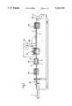
- FIG. 1schematically illustrates an overview of a packaging line with an apparatus embodying the invention
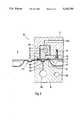
- FIG. 2schematically illustrates in an enlarged scale a work station A4 of FIG. 1;
- FIG. 3schematically illustrates a package produced according to the method of the invention on a packaging line according to FIG. 1;
- FIG. 4is a schematic cross-sectional view A-B of FIG. 3;
- FIG. 5schematically illustrates again in an enlarged scale a detail X of FIG. 4.
- FIG. 1illustrates, in a very simplified manner, a packaging line which is equipped with suitable operating means to carry out the method of the invention.
- a frame 1includes two conveyor devices F1 and F2 to introduce the bottom foil UF utilizing a conveyor device F1 and the top foil OF utilizing a conveyor device F2. The conveying directions are shown by arrows 2.
- the bottom foil UFis first shaped in a work station A1 so that a storage space 3, which can be filled with a material 4 to be packaged, is created in the bottom foil UF.
- the top foil OFis supplied in a following hot-sealing tool A2, is placed onto the bottom foil UF and is sealed to same.
- a preheating tool A3follows downstream thereafter in conveying direction followed by a forming tool A4 in which a resealing area or resealable portion 51 is created.
- the separation of the individual packages 5 by longitudinal and cross-cutting devicesfinally takes place in a work station A5.
- the preheating tool A3consisting of an upper part 6 and a lower part 7 has a heater 8, with the help of which the entire resealing area 51 is heated (FIG. 3).
- the resealing areais heated directly by the surfaces of the upper part 6 and of the lower part 7, which surfaces abut one another under contact pressure to clamp the resealing area therebetween.
- the resealing area 51 accompanying the hot-sealing areas existing on the package 5is advantageously preheated to a temperature which lies just below the temperature necessary for a plastification of the foils of OF and UF.
- the forming tool A4 following downstream in conveying directionis illustrated in detail in FIG. 2. It too is divided into two parts and consists of an upper part 9 and a lower part 10. It is to be understood that the divided tools 6, 7 and 9, 10 are movable vertically relative to one another; it is common for the lower part 7 or 10 to be designed so that it can be lowered.
- the lower part 10has a receiving means 101 into which is received the storage space 3 in the lower foil. A flow channel 102 in the lower part 10 is used to cool the lower part 10.
- a plurality of recesses 104are provided in a pressure surface 103 of the lower part 10, which recesses are each connected to an outlet passageway 106 by means of a connecting bore 105, which outlet passageway 106 in turn is connected to an underpressure source so that the recesses 104 can be evacuated.
- Each recess 104represents a matrix for a closing or closure element 511, with the entirety of all closing elements 511 representing the resealing area 51.
- the shape of the recesses 104determines thereby also the shape of the closing elements 511.
- FIG. 3shows that they are closing elements 511 ("knubs"), which are square in cross section and rectangular in longitudinal cross section.
- the upper part 9has a heating element 91 which can be heated by electrical heating cartridges 92 and is stored with only little movement in a through recess 93.
- a cover plate 95 fastened with screws 94 to the upper part 9locks the heating element 91 to the upper part 9.
- a significant spaceis provided between the heating element 91 and an interior wall 931 of the recess 93, which space facilitates a pneumatic connection between an outlet passageway 932 and a gap directly above the top foil OF sealed to the bottom foil UF, which gap is also directly above the recess 104 of the lower part 10.
- the gapwhich is pneumatically isolated from the surroundings U by seals 11 provided in grooves 96, is associated with the resealing area 51.
- the seals 11can be any type of sealing material such as gasket cord.
- FIGS. 3 to 5illustrate in detail a finished package 5 already equipped with a resealing area 51.
- the top foil OF, or the bottom foil UFwhich are hot-sealed with one another and enclose the material 4 to be packaged airtight in the storage space 3, are already cut to size with respect to length and width.
- the resealing area 511exists here on all sides and consists of a plurality of closing elements 511 which can be easily recognized as having a cup-like cross-section in FIG. 5. It is to be understood that the shape of the closing elements 511 can be practically as desired. They are shown in the drawing with a slight releasing slope for facilitating a comfortable release from the recesses 104.
- each knub or closing element formed in the bottom foilis perforated so that no air is entrapped between the knubs of the top and bottom foil during closing.
- the perforationsare formed in the bottom foil prior to supplying the top foil.
- the not-yet-cut packages 5After the not-yet-cut packages 5 have left the heat-sealing tool A2 and have reached the preheating tool A3, they are preheated here in order to be able to utilize the time available in the next following forming tool A4 exclusively for the manufacture of the closing elements 511.
- the preheating taskeffects a heating up to a temperature in which the foils OF and UF are just not yet plastically formable.
- the already preheated package 5is subsequently moved into the forming tool A4.
- the resealing area 51is clamped between the divided tools 9 and 10, particularly the pressure surfaces 97 and 103, thereon to cause the storage space 3 to be pneumatically insulated or hermetically isolated from the surroundings U by the seal 11.
- the outlet passageway 932is subsequently connected to an underpressure source so that the top foil OF (with the bottom foil UF sealed thereon) rests on the heating element 91 between the two seals 11.
- the two adjoining foils OF and UFare heated up further with the help of the heater 92 so that they can be plastically deformed.
- the outlet passageway 932is subsequently connected to an excess pressure source, with the help of which the foils OF and UF are pressed in the area of the recesses 104 in the lower part 10 into the recesses.
- the recesses 104are at the same 10 time evacuated with the help of an underpressure source acting through the outlet passageway 106 and the deformation of the foils OF and UF is thus supported.
- the closing elements 511are created in this manner.
- the lower part 10is during this time cooled so much with the help of the cooling medium flowing through the flow channel 102 that the foils OF and UF quickly lose their plasticity in the recess 104 when they come into contact with its wall. They keep then merely a certain residual elasticity which is sufficient to overcome, for example, an undercut provided in the recess 104.
- the package 5 completed in this manneris thereafter separated in the work station A5; the now complete packages 5 are removed from the area of the packaging machine by a conveyor belt.
Landscapes
- Engineering & Computer Science (AREA)
- Mechanical Engineering (AREA)
- Closing Of Containers (AREA)
- Package Closures (AREA)
- Making Paper Articles (AREA)
- Lining Or Joining Of Plastics Or The Like (AREA)
Abstract
Description
Claims (17)
Applications Claiming Priority (2)
| Application Number | Priority Date | Filing Date | Title |
|---|---|---|---|
| DE4211333 | 1992-04-04 | ||
| DE4211333 | 1992-04-04 |
Publications (1)
| Publication Number | Publication Date |
|---|---|
| US5331791Atrue US5331791A (en) | 1994-07-26 |
Family
ID=6456070
Family Applications (1)
| Application Number | Title | Priority Date | Filing Date |
|---|---|---|---|
| US07/966,135Expired - Fee RelatedUS5331791A (en) | 1992-04-04 | 1992-10-23 | Method and apparatus for the manufacture of a resealable package |
Country Status (4)
| Country | Link |
|---|---|
| US (1) | US5331791A (en) |
| JP (1) | JPH0648404A (en) |
| CA (1) | CA2079043A1 (en) |
| MX (1) | MX9205781A (en) |
Cited By (18)
| Publication number | Priority date | Publication date | Assignee | Title |
|---|---|---|---|---|
| US5784858A (en)* | 1996-04-08 | 1998-07-28 | Oliver Products Company | Drawer action tray sealing machine |
| US5791120A (en)* | 1997-06-02 | 1998-08-11 | Oliver Products Company | Tray sealing platen and seal apparatus |
| US5937615A (en)* | 1997-05-22 | 1999-08-17 | Forman; Harold M. | Apparatus for making resealable packages |
| US5983607A (en)* | 1997-03-03 | 1999-11-16 | Abbott Laboratories | Heat sealer and method for using same |
| AU739014B2 (en)* | 1999-05-12 | 2001-10-04 | Harold M. Forman | Resealable package, method and apparatus |
| US6436500B1 (en) | 2000-10-27 | 2002-08-20 | 3 Sigma Corporation | Package reclosure system and method |
| JP3322154B2 (en) | 1997-03-10 | 2002-09-09 | 凸版印刷株式会社 | Paper tray container manufacturing equipment |
| US6625955B2 (en)* | 2000-06-28 | 2003-09-30 | Aylward Enterprises, Inc. | Methods for forming product package with recloseable locking mechanism |
| US20050103678A1 (en)* | 2002-03-26 | 2005-05-19 | Clark Verna L. | Method for forming a laminate assembly and products formed thereby |
| EP1140653B2 (en)† | 1998-12-21 | 2007-12-19 | CFS GmbH Kempten | Resealable plastic packaging with at least one knob |
| US20100233428A1 (en)* | 2009-03-13 | 2010-09-16 | Keith Joseph Stone | Article having a seal and process for forming the same |
| US20110120064A1 (en)* | 2009-11-25 | 2011-05-26 | Uhlmann Pac-Systeme Gmbh & Co. Kg | Sealing station |
| US20110223388A1 (en)* | 2010-03-11 | 2011-09-15 | Keith Joseph Stone | Process for making a film/nonwoven laminate |
| US9387943B2 (en) | 2010-12-21 | 2016-07-12 | Tetra Laval Holdings & Finance S.A. | Forming member for forming sealed packages of pourable food products from a tube of packaging material |
| US10391717B2 (en)* | 2014-08-28 | 2019-08-27 | GlaxoSmithKline, LLC | Package and heat sealing device |
| US11034474B2 (en)* | 2016-10-31 | 2021-06-15 | Ross Industries, Inc. | Dual purpose seal head assembly, tray sealing system, and method therefor |
| US20210394943A1 (en)* | 2020-06-18 | 2021-12-23 | Multivac Sepp Haggenmueller Se & Co. Kg | Sealing supported by pressurized air |
| US20220135262A1 (en)* | 2019-08-08 | 2022-05-05 | Ckd Corporation | Blister packing machine and blister pack manufacturing method |
Citations (11)
| Publication number | Priority date | Publication date | Assignee | Title |
|---|---|---|---|---|
| US2918767A (en)* | 1954-03-02 | 1959-12-29 | Swift & Co | Packaging apparatus |
| US3198683A (en)* | 1960-10-26 | 1965-08-03 | Dow Chemical Co | Apparatus for sealing and folding flanged edges of containers |
| US3720038A (en)* | 1971-03-26 | 1973-03-13 | Reynolds Metals Co | Method and apparatus for covering open ended container bodies |
| US3760563A (en)* | 1971-12-13 | 1973-09-25 | G Zimmermann | Drawing apparatus for sealing containers |
| US4707213A (en)* | 1985-11-12 | 1987-11-17 | Continental Can Company, Inc. | Induction heating unit for heat bonding a lid having a metallic layer to a container |
| US4870800A (en)* | 1988-04-05 | 1989-10-03 | Nikka Co., Ltd. | Inert gas-filling and sealing device, heat sealing device and packaging apparatus using these devices |
| US5010714A (en)* | 1989-08-03 | 1991-04-30 | 501 Multivac Sepp Haggnemuller Kg | Packaging machine |
| EP0434447A1 (en)* | 1989-12-21 | 1991-06-26 | E.I. Du Pont De Nemours And Company | Assembling device to form a releasable bond between adjacent surface elements and method for manufacturing this assembling device |
| US5031383A (en)* | 1988-11-03 | 1991-07-16 | Oscar Mayer Foods Corporation | Method of forming a food package |
| US5044145A (en)* | 1989-03-23 | 1991-09-03 | W. R. Grace & Co.-Conn. | Film packaging |
| US5163269A (en)* | 1990-09-10 | 1992-11-17 | Bryan Foods, Inc. | Method for making reclosable package |
- 1992
- 1992-09-24CACA002079043Apatent/CA2079043A1/ennot_activeAbandoned
- 1992-10-08MXMX9205781Apatent/MX9205781A/ennot_activeApplication Discontinuation
- 1992-10-23USUS07/966,135patent/US5331791A/ennot_activeExpired - Fee Related
- 1993
- 1993-04-02JPJP5076528Apatent/JPH0648404A/enactivePending
Patent Citations (11)
| Publication number | Priority date | Publication date | Assignee | Title |
|---|---|---|---|---|
| US2918767A (en)* | 1954-03-02 | 1959-12-29 | Swift & Co | Packaging apparatus |
| US3198683A (en)* | 1960-10-26 | 1965-08-03 | Dow Chemical Co | Apparatus for sealing and folding flanged edges of containers |
| US3720038A (en)* | 1971-03-26 | 1973-03-13 | Reynolds Metals Co | Method and apparatus for covering open ended container bodies |
| US3760563A (en)* | 1971-12-13 | 1973-09-25 | G Zimmermann | Drawing apparatus for sealing containers |
| US4707213A (en)* | 1985-11-12 | 1987-11-17 | Continental Can Company, Inc. | Induction heating unit for heat bonding a lid having a metallic layer to a container |
| US4870800A (en)* | 1988-04-05 | 1989-10-03 | Nikka Co., Ltd. | Inert gas-filling and sealing device, heat sealing device and packaging apparatus using these devices |
| US5031383A (en)* | 1988-11-03 | 1991-07-16 | Oscar Mayer Foods Corporation | Method of forming a food package |
| US5044145A (en)* | 1989-03-23 | 1991-09-03 | W. R. Grace & Co.-Conn. | Film packaging |
| US5010714A (en)* | 1989-08-03 | 1991-04-30 | 501 Multivac Sepp Haggnemuller Kg | Packaging machine |
| EP0434447A1 (en)* | 1989-12-21 | 1991-06-26 | E.I. Du Pont De Nemours And Company | Assembling device to form a releasable bond between adjacent surface elements and method for manufacturing this assembling device |
| US5163269A (en)* | 1990-09-10 | 1992-11-17 | Bryan Foods, Inc. | Method for making reclosable package |
Cited By (28)
| Publication number | Priority date | Publication date | Assignee | Title |
|---|---|---|---|---|
| US5946887A (en)* | 1996-04-08 | 1999-09-07 | Oliver Products Company | Drawer action tray sealing machine |
| US5784858A (en)* | 1996-04-08 | 1998-07-28 | Oliver Products Company | Drawer action tray sealing machine |
| US5983607A (en)* | 1997-03-03 | 1999-11-16 | Abbott Laboratories | Heat sealer and method for using same |
| JP3322154B2 (en) | 1997-03-10 | 2002-09-09 | 凸版印刷株式会社 | Paper tray container manufacturing equipment |
| US5937615A (en)* | 1997-05-22 | 1999-08-17 | Forman; Harold M. | Apparatus for making resealable packages |
| US5791120A (en)* | 1997-06-02 | 1998-08-11 | Oliver Products Company | Tray sealing platen and seal apparatus |
| EP1140653B2 (en)† | 1998-12-21 | 2007-12-19 | CFS GmbH Kempten | Resealable plastic packaging with at least one knob |
| AU739014B2 (en)* | 1999-05-12 | 2001-10-04 | Harold M. Forman | Resealable package, method and apparatus |
| AU739014C (en)* | 1999-05-12 | 2002-06-06 | Harold M. Forman | Resealable package, method and apparatus |
| US6625955B2 (en)* | 2000-06-28 | 2003-09-30 | Aylward Enterprises, Inc. | Methods for forming product package with recloseable locking mechanism |
| US6436500B1 (en) | 2000-10-27 | 2002-08-20 | 3 Sigma Corporation | Package reclosure system and method |
| US20050103678A1 (en)* | 2002-03-26 | 2005-05-19 | Clark Verna L. | Method for forming a laminate assembly and products formed thereby |
| US7448184B2 (en)* | 2002-03-26 | 2008-11-11 | Glaxo Group Limited | Method for forming a laminate assembly with an ultrasonic welder |
| US9271879B2 (en)* | 2009-03-13 | 2016-03-01 | The Procter & Gamble Company | Article having a seal and process for forming the same |
| US20100233428A1 (en)* | 2009-03-13 | 2010-09-16 | Keith Joseph Stone | Article having a seal and process for forming the same |
| US10543637B2 (en) | 2009-03-13 | 2020-01-28 | The Procter & Gamble Company | Article having a seal and process for forming the same |
| US20110120064A1 (en)* | 2009-11-25 | 2011-05-26 | Uhlmann Pac-Systeme Gmbh & Co. Kg | Sealing station |
| US9021770B2 (en) | 2009-11-25 | 2015-05-05 | Uhlmann Pac-Systeme Gmbh & Co. Kg | Sealing station |
| EP2327533A1 (en)* | 2009-11-25 | 2011-06-01 | Uhlmann Pac-Systeme GmbH & Co. KG | Sealing station |
| US9079324B2 (en) | 2010-03-11 | 2015-07-14 | The Procter & Gamble Company | Process for making a film/nonwoven laminate |
| US20110223388A1 (en)* | 2010-03-11 | 2011-09-15 | Keith Joseph Stone | Process for making a film/nonwoven laminate |
| US9387943B2 (en) | 2010-12-21 | 2016-07-12 | Tetra Laval Holdings & Finance S.A. | Forming member for forming sealed packages of pourable food products from a tube of packaging material |
| US10391717B2 (en)* | 2014-08-28 | 2019-08-27 | GlaxoSmithKline, LLC | Package and heat sealing device |
| US11034474B2 (en)* | 2016-10-31 | 2021-06-15 | Ross Industries, Inc. | Dual purpose seal head assembly, tray sealing system, and method therefor |
| US20220135262A1 (en)* | 2019-08-08 | 2022-05-05 | Ckd Corporation | Blister packing machine and blister pack manufacturing method |
| US11724840B2 (en)* | 2019-08-08 | 2023-08-15 | Ckd Corporation | Blister packing machine and blister pack manufacturing method |
| US20210394943A1 (en)* | 2020-06-18 | 2021-12-23 | Multivac Sepp Haggenmueller Se & Co. Kg | Sealing supported by pressurized air |
| US11649082B2 (en)* | 2020-06-18 | 2023-05-16 | Multiv Ac Sepp Haggenmueller Se & Co. Kg | Sealing supported by pressurized air |
Also Published As
| Publication number | Publication date |
|---|---|
| JPH0648404A (en) | 1994-02-22 |
| CA2079043A1 (en) | 1993-10-05 |
| MX9205781A (en) | 1993-10-01 |
Similar Documents
| Publication | Publication Date | Title |
|---|---|---|
| US5331791A (en) | Method and apparatus for the manufacture of a resealable package | |
| US5010714A (en) | Packaging machine | |
| US5105603A (en) | Packaging machine for producing a reclosable package for a product | |
| DK3024733T3 (en) | Modified atmosphere, shrinkage or vacuum packer and method | |
| EP0131862B1 (en) | Method for manufacturing an angled and cylindrical container | |
| US20100287893A1 (en) | Packaging machine and method for closing containers with lids | |
| US5987855A (en) | Method of and apparatus for sealing surgical suture packages | |
| US7665281B2 (en) | Machine for making packaging with form-fit connection | |
| EP1984250A1 (en) | Packaging machine for the production of a packaging having a recess in the packaging cavity edge | |
| JP2003095220A (en) | Film hot molding method and apparatus for blister packer | |
| EP0190384A2 (en) | Apparatus for thermally fixing the formed thermoplastic products | |
| KR20010052725A (en) | Apparatus and methods for twin sheet thermoforming | |
| HU211410B (en) | Device for heating platelike bodies made of deep-drawing plastic material | |
| EP0564695B1 (en) | Method and device for making a reclosable package | |
| US4137688A (en) | Method of vacuum packing objects in plastic foil | |
| CN1240381A (en) | Method and mould tools for injection moulding a plastics material part in a packaging sheet material | |
| US20140033647A1 (en) | Apparatus and methods for packaging a product | |
| JP2023160760A (en) | Forming device and method for forming cup into packaging material | |
| US6929141B1 (en) | System for thermoforming sheet material to obtain containers therefrom | |
| JPH04212823A (en) | Manufacture of multi-layer molded product | |
| US20050239622A1 (en) | Bags comprising closure profiles operated by a slider | |
| CN214649576U (en) | Sealing die for sealing groove and stretch film packaging machine | |
| JP2024521002A (en) | Apparatus and method for manufacturing a closure system for a container - Patents.com | |
| US3474591A (en) | Automatic packaging apparatus with removable die covering | |
| EP0530899A1 (en) | Heat-sealed container and cover |
Legal Events
| Date | Code | Title | Description |
|---|---|---|---|
| AS | Assignment | Owner name:KRAEMER & GREBE GMBH & CO. KG MASCHINENFABRIK IM R Free format text:ASSIGNMENT OF ASSIGNORS INTEREST.;ASSIGNORS:SCHMECK, ALFRED;FUX, RUDOLF;REEL/FRAME:006301/0688 Effective date:19920828 | |
| AS | Assignment | Owner name:TETRA LAVAL CONVENIENCE FOOD GMBH & CO. KG, GERMAN Free format text:CHANGE OF NAME;ASSIGNOR:KRAEMER + GREBE GMBH & CO. KG MASCHINENFABRIK;REEL/FRAME:007244/0299 Effective date:19940613 | |
| AS | Assignment | Owner name:TIROMAT KRAEMER + GREBE GMBH & CO. KG, GERMANY Free format text:CHANGE OF NAME;ASSIGNOR:TETRA LAVAL CONVENIENCE FOOD GMBH & CO. KG;REEL/FRAME:008753/0581 Effective date:19970516 | |
| FEPP | Fee payment procedure | Free format text:PAYOR NUMBER ASSIGNED (ORIGINAL EVENT CODE: ASPN); ENTITY STATUS OF PATENT OWNER: LARGE ENTITY | |
| FPAY | Fee payment | Year of fee payment:4 | |
| REMI | Maintenance fee reminder mailed | ||
| LAPS | Lapse for failure to pay maintenance fees | ||
| STCH | Information on status: patent discontinuation | Free format text:PATENT EXPIRED DUE TO NONPAYMENT OF MAINTENANCE FEES UNDER 37 CFR 1.362 | |
| FP | Lapsed due to failure to pay maintenance fee | Effective date:20020726 |