US5331357A - Illumination assembly - Google Patents
Illumination assemblyDownload PDFInfo
- Publication number
- US5331357A US5331357AUS07/922,914US92291492AUS5331357AUS 5331357 AUS5331357 AUS 5331357AUS 92291492 AUS92291492 AUS 92291492AUS 5331357 AUS5331357 AUS 5331357A
- Authority
- US
- United States
- Prior art keywords
- lens
- housing
- disposed
- aperture
- cane
- Prior art date
- Legal status (The legal status is an assumption and is not a legal conclusion. Google has not performed a legal analysis and makes no representation as to the accuracy of the status listed.)
- Expired - Fee Related
Links
- 238000005286illuminationMethods0.000titleclaimsabstractdescription60
- 239000000835fiberSubstances0.000claimsabstractdescription50
- 239000003365glass fiberSubstances0.000description6
- 239000004593EpoxySubstances0.000description4
- XUIMIQQOPSSXEZ-UHFFFAOYSA-NSiliconChemical compound[Si]XUIMIQQOPSSXEZ-UHFFFAOYSA-N0.000description4
- 229910052710siliconInorganic materials0.000description4
- 239000010703siliconSubstances0.000description4
- 238000000034methodMethods0.000description3
- 230000003287optical effectEffects0.000description3
- 230000000712assemblyEffects0.000description1
- 238000000429assemblyMethods0.000description1
- 238000005452bendingMethods0.000description1
- 238000005266castingMethods0.000description1
- 239000000463materialSubstances0.000description1
- 230000013011matingEffects0.000description1
- 230000001681protective effectEffects0.000description1
- 238000000926separation methodMethods0.000description1
Images


Classifications
- G—PHYSICS
- G02—OPTICS
- G02C—SPECTACLES; SUNGLASSES OR GOGGLES INSOFAR AS THEY HAVE THE SAME FEATURES AS SPECTACLES; CONTACT LENSES
- G02C11/00—Non-optical adjuncts; Attachment thereof
- G02C11/04—Illuminating means
- G—PHYSICS
- G02—OPTICS
- G02B—OPTICAL ELEMENTS, SYSTEMS OR APPARATUS
- G02B6/00—Light guides; Structural details of arrangements comprising light guides and other optical elements, e.g. couplings
- G02B6/0001—Light guides; Structural details of arrangements comprising light guides and other optical elements, e.g. couplings specially adapted for lighting devices or systems
- G02B6/0005—Light guides; Structural details of arrangements comprising light guides and other optical elements, e.g. couplings specially adapted for lighting devices or systems the light guides being of the fibre type
- G02B6/0008—Light guides; Structural details of arrangements comprising light guides and other optical elements, e.g. couplings specially adapted for lighting devices or systems the light guides being of the fibre type the light being emitted at the end of the fibre
- G—PHYSICS
- G02—OPTICS
- G02C—SPECTACLES; SUNGLASSES OR GOGGLES INSOFAR AS THEY HAVE THE SAME FEATURES AS SPECTACLES; CONTACT LENSES
- G02C7/00—Optical parts
- G02C7/02—Lenses; Lens systems ; Methods of designing lenses
- G02C7/08—Auxiliary lenses; Arrangements for varying focal length
- G02C7/088—Lens systems mounted to spectacles
Definitions
- This inventionrelates generally to illumination systems and more particularly to telescopic spectacle illumination systems.
- Telescopic spectaclesare used by surgeons and others who must work with minute objects.
- the telescopesare arranged either in pairs, with one telescope positioned for viewing by each eye of the wearer, or alternatively, with a single telescope positioned in the center of the spectacles.
- the image path from the single telescopeis divided into two images, with one image being viewed by each eye.
- Telescopic spectaclesmay be constructed either with or without an integral object illuminator.
- ShadowsWhen the illumination, either supplied by a light source which is integral with the telescopic spectacles or otherwise provided externally, does not illuminate the object to be viewed along the viewing image path, portions of the object in the light path cast shadows.
- the casting of shadowsincreases the difficulty in viewing other portions of small objects, for example within an operating field. Shadows are least when the illumination beam and the viewing image are substantially aligned along the same optical path. Conversely shadows increase in size as the angle of divergence between the illumination beam and the viewing image path increases.
- an illumination assemblyincludes a lens housing having a first end and a second end, a first lens having first and second opposing surfaces with the first lens being disposed in a first end of the lens housing.
- the illumination assemblyfurther includes a cane having a first surface and a second surface with the cane being disposed in the lens housing with the first surface of the cane being spaced a predetermined distance from the first surface of the lens and wherein the second surface of the cane is provided having a polished surface.
- a fiber optic bundle having a first end and a second endis disposed in the lens housing with the first end of the fiber optic bundle having a polished surface and disposed adjacent the second surface of the cane.
- an illumination assemblywhich may be disposed on a spectacle frame, for example.
- a second lens having first and second opposing surfacesmay be disposed in the lens housing with the first surface of the second lens adjacent the second surface of the first lens and the second surface of the second lens adjacent an aperture of the lens housing.
- the first lensmay be provided as a singlet and the second lens may be provided as a doublet to thus direct and focus light fed from a light source through the fiber optic bundle to the cane and lenses.
- the fiber optic bundle having a flat polished surfacethe diameter of the outermost surface area of the polished surface is maximized.
- the second surface of the cane and the first surface of the fiber optic bundle having flat polished surfacesthe two surfaces may be disposed such that maximum contact occurs between the two surfaces.
- the cane, singlet lens and doublet lensprovide a focusing system which provides the illumination system having a convergent beam.
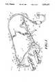
- FIG. 1is a perspective view of a pair of telescopic spectacles having an integral illumination assembly
- FIG. 2is a cross-sectional view along the lines 2--2 of FIG. 1;
- FIG. 3is a cross-sectional view along the lines 3--3 of FIG. 1;
- FIG. 4is a rear view of a portion of the frames shown in FIG. 1;
- FIG. 5is a top view of a locking ring
- FIG. 5Ais a cross sectional view of the locking ring taken along the lines 5A--5A of FIG. 5;
- FIGS. 6A--6Care a series of cross-sectional views taken along the lines 6--6 of FIG. 1 showing the steps involved in closing a temple arm.
- a pair of telescopic spectacles 10includes a frame 12 having a top frame portion 14 and a pair of rim portions 16, 16'.
- the rim portions 16, 16'are respectively attached to left and right sides of the top frame portion 14 to provide the frame having first and second apertures 18, 18'.
- Each aperture 18, 18'has disposed therein a lens 20, 20'.
- Each of the lenses 20, 20'may be provided having a hole (not numbered) therethrough in which a telescope 24 may be disposed.
- Each of the telescopes 24may be provided and disposed in the holes in a manner described in co-pending patent application Ser. No. 07/923,081 filed on Jul. 31, 1992 having named inventors Frederick Morris and Bernard Clark and assigned to the assignee of the present invention and incorporated herein by reference.
- lenses 20, 20'may be provided as prescriptive lenses or merely protective lenses.
- the top frame portion 14is provided having a bore 26, 26' through right and left ends thereof.
- An illumination assembly 28,is disposed through the bore 26.
- a like illumination assembly 28'is disposed through the bore26'.
- the illumination assembly 28includes a lens housing 32, a first lens 30 disposed in a first aperture of the lens housing 32, a spring housing 33, and an adapter housing 35 pivotally coupled to the spring housing 33 by a top adapter pin 56 and a bottom adapter pin (not shown).
- the illumination assembly 28is coupled to the frame 12 such that the lens 30 is disposed through the bore 26 and a first surface of the lens 30a is exposed through the bore 26 and slightly protrudes from a front surface 14a of the top frame portion 14.
- the illumination assembly 28will be further described in conjunction with FIG. 2, suffice it here to say however that the first lens 30 of the illumination assembly 28 is disposedsuch that light is directed to a predetermined viewing area.
- a frame temple 34here provided as a hollow tube, has a first end 34a coupled to the illumination assembly 28 and a second end 34b.
- the frame temple 34is here shown in the open position, however, as will be described further in conjunction with FIGS. 6A-6C, the adapter housing 35 may pivot about the adapter pivot pins 56 to such that the frame temple 34may alternatively be placed in a closed position.
- An illumination cableincludes a potted fiber bundle 36 having a first numerical aperture.
- the fiber bundle 36may be covered by a silicon cover 37 as is generally known. Here, portions of the silicon cover have been removed to expose the fiber bundle 36.
- a first end of the fiber bundle 36is disposed through the hollow region of the frame temple 34 and coupled to the illumination assembly 28 in a manner to be described herein below in conjunction with FIG. 2.
- a second end of the glass fiber 36is coupled to a first port of a bifurcated junction box 42.
- the glass fibers 36, 36'are provided by splitting a first fiber optic bundle 40, here said fiber optic bundle having a diameter typically of about 5 millimeters.
- the fiber optic bundle 40is split into a pair of glass fibers 36, 36' each having a diameter typically of about 3.5 millimeters.
- the glass fibers 36,36'are here separated and disposed in separate ports of the bifurcated junction box 42.
- the junction box 42maintains the separation between eachof the glass fibers 36, 36'.
- Each of the fibers 36is subsequently coupled to a respective one of the illumination assemblies 28, 28'.
- the unsplit portion of the fiber optic bundle 40is coupled to a light source 38.
- a first end of the fiber 36is coupled to the illumination assembly 28 and a second end of the fiber 36 is coupled to the light source 38.
- Each end of a headband 43is coupled to one of the frame temples 34 by a headband mounting strap 45.
- the headband 43is disposed to securely hold the telescopic spectacles 10 to the head of a user (not shown).
- the silicon cover 37ends and is bonded to the second end of the temple 34b.
- the headband mounting strap 45is disposed about this bonded region to prevent the cover 37 from being peeled back and exposing the fiber optic cable 36.
- the illumination assembly 28includes the lens housing 32 in which the first lens 30 is disposed.
- the lens housingis provided having a first cavity region havinga length L1 typically of about 0.337 inch and an internal diameter D1 typically of about 0.473 inch
- the lens 30is disposed in the first cavity region and is here shown to be provided from first and second convex lenses 30a and 30b which are bonded together to provide the lens 30 as a doublet.
- a third convex lens 44here provided as a singlet, is also disposed in the first cavity region with a first surface of the third lens44 in contact with a first surface of the lens 30b.
- a second surface of thethird lensis disposed in contact with a first internal surface of the lenshousing 32.
- the doublet 30 and singlet 44are each fixed to the lens housing 32 via an epoxy.
- the lens housingalso has a second cavity region having a length L2 typically of about 0.329 inch and a diameter D2 typically of about 0.312 inch.
- the lens housingfurther includes a third cavity region having a length L3 typically of about 0.087 inch and a diameter D3 typically of about 0.135 inch.
- a cane 46 having a diameter typically of about 0.140 inch and a length typically of about 0.250 inchmay be disposed in a fourth cavity region of the lens housing 32.
- the cane 46is provided as a single fiber optical cane having a numerical aperture corresponding to the numerical aperture as the fiber bundle 36.
- Single fiber optical canessuch as cane 46 are commercially available as is well known to those of skill in the art.
- a first end of the cane 46is provided having a flat polish.
- a first surface of the fiber bundle 36is provided having a like polish to thus provide a flush interface between the first surface of the cane 46 and the first surface of the fiber 36.
- the cane 46acts as a homogenizer to properly couple the light from the glass fiber 36 to the singlet 44.
- the spring housing 33is provided as a sleeve having a base region 33a having a bore therethrough and a pair of sleeve walls disposed on inner and outer diameters of the base region 33a with a cavity region between the two sleeve walls 33b, 33c.
- the spring housing 33is disposed about a first end of the lens housing 32.
- a pairof pins 48 disposed in the lens housing 33align with a corresponding pair of holes in the lens housing to connect the lens housing 32 to the spring housing 33.
- the pins 48prevent the spring housing 33 from rotating with respect to the lens housing 32.
- a spring 50is disposed in the cavity region and alocking ring 52 is disposed over an open portion of the cavity opposite said base region 33a to retain the spring in the cavity.
- the adapter housing 35is disposed over the second end of the lens housing 32 to fasten the fiber optic bundle 36 in the lens housing 32.
- a pair of adapter pins 56pivotally connect the adapter 35 to the spring housing 33 such that the adapter 35 may pivot with respect to the spring housing 33. This allows the temples 34 to be placed in open and closed positions as will be described further in conjunction with FIG. 6.
- the temple 34is here provided as a hollow tube having an outside diameter typically of about 0.188 inch and diameter typically of about 0.150 inch.
- the fiber 36 having an outside diameter typically of about 0.138 inchis disposed through the hollow center of the frame temple 34.
- the lenses 30 and 44are provided as 12 mm lenses. However, in some applications it may be desirable to reduce the size of the lenses to gain the advantage of a concomitant reduction in the size of the illumination assembly 28.
- the lenses 30, 44may be provided as 8 mm lensesand the corresponding dimensions of the lens housing 32, cane 46, spring housing 33, adapter 35 and fiber bundle 36 may be adjusted accordingly.
- a portion 12' of the frame 12 (FIG. 1) including the top frame portion 14 and the rim portion 16is shown having four threaded holes 60a-60d provided in a rear surface 14b thereof.
- the bore 26of the top frame portion 14 (FIG. 1)is here shown to have a shape corresponding to a spherical pocket 26 which mates to the first end of thelens housing 32 (FIGS. 1, 2, 3). That is, a first region 31 (FIG. 3) of thelens housing 32 (FIGS. 1, 2, 3) is provided having an outer radius which corresponds to the inner radius of the spherically shaped bore 26.
- the outer radius of the region 31 (FIGS. 1, 2, 3)is typically of about 0.285 inch.
- the first region of the lens housing 31(FIGS. 1, 2, 3) and the spherically shaped bore 26 fit together similar to a ball and socket arrangement wherein the lens housing 32 (FIGS. 1, 2, 3) acts as theball and the bore 26 acts as the socket.
- a lens housing clamp 62having four clearance holes 62a-62d disposed therethrough in a pattern corresponding to the pattern of the threaded holes 60a-60d (FIG. 4) is used to fasten the lens housing 32 to the frame 12 via screws (not shown) disposed through each of the clearance holes 62a-62d and threaded into the holes 60a-60d (FIG. 4).
- the illumination assembly 28(FIGS. 1, 2, 3) is moveable within the bore and may be directed at one of a range of angles.
- the illumination assembly 28may be positioned to point at a particular working distance and declination angle. This step may be accomplished using the alignment apparatus described in co-pending patent application identified as having serial no. 07/923,081 filed on Jul. 31, 1992 having named inventors Frederick Morris and Bernard Clark and assigned to the assignee of the present invention.
- Other methods of coursemay also be used to aim the illumination assembly 28 (FIGS. 1, 2, 3) in a predetermined direction.
- an ultra-violet (UV) bonding epoxymay be disposed on the lens housing 32 to temporarily fix the illuminationassembly 28 in a predetermined position within the socket 26. Suffice it here to say that when the illumination assembly 28 is disposed in the desired location and pointing at the correct working distance and declination angles, the bonding epoxy is exposed to UV light and the illumination assembly 28 is thus permanently bonded in place and illuminates a viewing area corresponding to a predetermined working distance and declination angle.
- UVultra-violet
- the telescopic spectacle assembly 10may then be disposed in a holding fixture, such as a vice (not shown) for example, and a final bonding material may be disposed on the illumination assembly 28 and curedto permanently hold the lens housing 32 in the socket 26 of the frame 12 atthe declination and convergence angle corresponding to the user.
- a holding fixturesuch as a vice (not shown) for example
- a final bonding materialmay be disposed on the illumination assembly 28 and curedto permanently hold the lens housing 32 in the socket 26 of the frame 12 atthe declination and convergence angle corresponding to the user.
- Steps to assemble the illumination assembly 28will now be described.
- the optics including the lenses 30, 44 and the cane46 disposed in lens housing 32may be assembled independently from the temple 34.
- the fibers 36are fed through the temple 34 while the temple 34 is straight.
- the temple 34is then cold formed in a forming die to a predetermined shape selected to fit a user.
- the bending of the temple 34may be accomplished using commercially available tools as is generally known.
- a region 34c (FIG. 1) of the templemay optionally be flattened in an area which will rest above the user's ear. It should be noted however that the region 34c is flattened care should be taken to not destroy any of the fibers in the fiber bundle 36 disposed through the temple 34.
- the portion of the fiber bundle 36 extending past the end of the temple 34amay then be polished using any technique well known to those of skill in the art to provide the first end of the fiber 36 having a flat surface.
- the lenses 30, 44 and cane 46are inserted and bonded into predetermined positions of the lens housing 32.
- the spring housing 33is disposed over lens housing 32.
- the pins 48 (FIG. 3) on the spring housing 33should mate with corresponding holes in the lens housing 32.
- the spring 50is disposed in the spring housing cavity.
- the locking ring 52is then pressed onto the back of the lens housing 33 tohold the spring 50 in place.
- the lens housing 32 with the spring housing 33attached theretomay then be inserted into the spherical socket 26 in the rear surface 14b of frame 12.
- the clamp 62is then place over the back of the lens housing 32 and screws (not shown) are inserted through the holes 62a-62d of the clamp 62 and into the frame 12 to secure the clamp 62 and thus the lens housing 32 to the frame 12.
- screws(not shown) are inserted through the holes 62a-62d of the clamp 62 and into the frame 12 to secure the clamp 62 and thus the lens housing 32 to the frame 12.
- the lens housing 32should be positioned such that the front contour of the lens housing 32 substantially corresponds tothe contour of the first surface of the frame 14a.
- the headband mounting strap 45may be disposed over the temple 34 with the and the adapter 35 may be placed over the temple 34 andinserted into spring housing 33.
- the proper orientation of the temple 34 within the adapter 35is then established and the temple 34 is fixed to the adapter 35 by bonding with epoxy or by using any other technique well known to those of skill in the art.
- the adapter 35 having the temple 34 bonded theretomay now be connected to the spring housing 33 by pressing the adapter pins 56 into the corresponding mating holes located in the spring housing 33 and the adapter 35 to thus provide the assembled illumination assembly 28.
- the lens housing 32may be bonded to the frame 12 to hold the lens housing in the desired position.
- the headband mounting strap 45may be bonded to the silicon cover 37 and the headstrap 44 may then be attached.
- FIGS. 6A-6Cin which like elements of the illumination assembly 28 of FIGS. 2 and 3 are provided having like designations, steps in closing the temple arm 34 will now be described. It should first be noted however that for clarity of viewing the lenses 30 and 44 have been omitted. It should also be noted that adapter 35 and temple arm 34 pivot about the adapter pins 56 which are clearly shown in FIGS. 1 and 2 but which are nor present in this view.
- FIG. 6Ashows the temple 34 in the full open position and thus the fiber 36is disposed against the surface of the cane 46.
- the surface of the fiber 36contacts the surface of the cane 46 however a gap typically of about 0.002 inch between the two surfaces is also acceptable.
- the fiber 36, temple 34, adapter 35 and spring housing33are separated from the cane 46 and lens housing 32 here a distance typically of about 0.125 inch.
- the base region 33a of the spring housing 33compresses the spring 50, however the pins 48 maintain contact between the lens housing 32 and spring housing 33.
- the adapter 35 and thus the temple 34may now freely pivot about the adapter pivot pins 56 (FIG. 2).
- the templeis free toswivel about the pins 56 (FIG. 2) to a fully closed position.
Landscapes
- Physics & Mathematics (AREA)
- Health & Medical Sciences (AREA)
- Ophthalmology & Optometry (AREA)
- General Physics & Mathematics (AREA)
- Optics & Photonics (AREA)
- General Health & Medical Sciences (AREA)
- Eyeglasses (AREA)
Abstract
Description
Claims (15)
Priority Applications (1)
| Application Number | Priority Date | Filing Date | Title |
|---|---|---|---|
| US07/922,914US5331357A (en) | 1992-07-31 | 1992-07-31 | Illumination assembly |
Applications Claiming Priority (1)
| Application Number | Priority Date | Filing Date | Title |
|---|---|---|---|
| US07/922,914US5331357A (en) | 1992-07-31 | 1992-07-31 | Illumination assembly |
Publications (1)
| Publication Number | Publication Date |
|---|---|
| US5331357Atrue US5331357A (en) | 1994-07-19 |
Family
ID=25447775
Family Applications (1)
| Application Number | Title | Priority Date | Filing Date |
|---|---|---|---|
| US07/922,914Expired - Fee RelatedUS5331357A (en) | 1992-07-31 | 1992-07-31 | Illumination assembly |
Country Status (1)
| Country | Link |
|---|---|
| US (1) | US5331357A (en) |
Cited By (54)
| Publication number | Priority date | Publication date | Assignee | Title |
|---|---|---|---|---|
| WO1996037730A1 (en) | 1995-05-23 | 1996-11-28 | Orascoptic Research, Inc. | Illumination assembly for dental and medical applications |
| USD388113S (en)* | 1996-10-11 | 1997-12-23 | Designs For Vision, Inc. | Combined eyeglasses and mounted headlight |
| WO2001018445A1 (en)* | 1999-09-02 | 2001-03-15 | Bernhard Strehl | Lamp device which is worn on the head |
| US6406194B1 (en)* | 2000-10-16 | 2002-06-18 | Delphi Technologies, Inc. | Expanding mount system for light emitting cable leads |
| WO2002099332A1 (en)* | 2001-04-17 | 2002-12-12 | Ego Scientific, Inc. | Lightweight high-intensity head-mounted illumination source |
| US6612695B2 (en) | 2001-11-07 | 2003-09-02 | Michael Waters | Lighted reading glasses |
| US20050248932A1 (en)* | 2004-05-07 | 2005-11-10 | Michael Waters | Clip-on light apparatus |
| US7008074B1 (en)* | 2002-12-10 | 2006-03-07 | Halm Gary V | Hands-free controlled light operation |
| US20070013865A1 (en)* | 2005-07-15 | 2007-01-18 | Lonnie Jordan | Illuminated reading glasses |
| USD583850S1 (en)* | 2007-12-18 | 2008-12-30 | Waleed Jabali | Combination binocular, eyeglasses, and adjustable headband assembly |
| US20100220494A1 (en)* | 2007-09-07 | 2010-09-02 | Nexxus Lighting, Inc. | Led lighting system |
| US7824052B1 (en) | 2007-03-16 | 2010-11-02 | Halm Gary V | Foot controlled light operation |
| US20100302502A1 (en)* | 2007-08-20 | 2010-12-02 | E-Gun Technology Co., Ltd. | Glasses with illumination function |
| USD628617S1 (en) | 2010-03-01 | 2010-12-07 | Michael Waters | Lighted glasses |
| US20110187989A1 (en)* | 2005-05-17 | 2011-08-04 | Michael Waters | Illuminated eyewear |
| USD648882S1 (en) | 2010-11-02 | 2011-11-15 | Halm Gary V | Combination light and IR detector |
| US20110305007A1 (en)* | 2009-11-23 | 2011-12-15 | Chang Byung J | Led illuminator with improved beam quality |
| US8152330B2 (en) | 2001-11-07 | 2012-04-10 | Michael Waters | Lighted reading glasses |
| US8235524B2 (en) | 2001-11-07 | 2012-08-07 | Michael Waters | Illuminated eyewear |
| US8333485B2 (en) | 2007-12-18 | 2012-12-18 | Michael Waters | Headwear with switch shielding portion |
| US8388164B2 (en) | 2005-05-17 | 2013-03-05 | Michael Waters | Hands-Free lighting devices |
| US8405489B1 (en) | 2010-06-28 | 2013-03-26 | Gary V. Halm | Master subservient light operation |
| USD682343S1 (en) | 2011-12-23 | 2013-05-14 | Michael Waters | Lighted glasses |
| US8444266B2 (en) | 2009-09-30 | 2013-05-21 | Michael Waters | Illuminated eyewear |
| US8485682B2 (en) | 2007-10-29 | 2013-07-16 | Waters Industries, Inc. | Illuminated eyeglass assembly |
| US8491118B2 (en) | 2001-11-07 | 2013-07-23 | Michael Waters | Lighted reading glasses |
| US8491145B2 (en) | 2007-12-18 | 2013-07-23 | Waters Industries, Inc. | Illuminated headgear having switch devices and packaging therefor |
| US8540364B2 (en) | 2010-09-14 | 2013-09-24 | Michael Waters | Lighted glasses |
| US8550651B2 (en) | 2007-12-18 | 2013-10-08 | Waters Industries, Inc. | Lighted hat |
| US8757831B2 (en) | 2007-12-18 | 2014-06-24 | Michael Waters | Headgear having an electrical device and power source mounted thereto |
| CN103955076A (en)* | 2014-05-20 | 2014-07-30 | 丹阳市精通眼镜技术创新服务中心有限公司 | Spectacles capable of observing image transfer |
| US8813268B1 (en)* | 2011-09-05 | 2014-08-26 | Outdoor Cap Company, Inc. | Lighted headwear with recessed light source and lens |
| US8979295B2 (en) | 2005-05-17 | 2015-03-17 | Michael Waters | Rechargeable lighted glasses |
| US9101174B2 (en) | 2011-11-04 | 2015-08-11 | Michael Waters | Hat with automated shut-off feature for electrical devices |
| US9383077B2 (en) | 2009-11-23 | 2016-07-05 | General Scientific Corporation | High-efficiency LED illuminator with improved beam quality |
| USD770143S1 (en) | 2014-05-23 | 2016-11-01 | Michael Waters | Beanie with means for illumination |
| US9494299B2 (en) | 2009-11-23 | 2016-11-15 | General Scientific Corporation | High-efficiency LED illuminator with improved beam quality and ventilated housing |
| US9526287B2 (en) | 2011-12-23 | 2016-12-27 | Michael Waters | Lighted hat |
| US9526292B2 (en) | 2005-05-17 | 2016-12-27 | Michael Waters | Power modules and headgear |
| US9568173B2 (en) | 2011-12-23 | 2017-02-14 | Michael Waters | Lighted hat |
| US9609902B2 (en) | 2011-12-23 | 2017-04-04 | Michael Waters | Headgear having a camera device |
| US9717633B2 (en) | 2013-03-15 | 2017-08-01 | Michael Waters | Lighted headgear |
| US9872530B2 (en) | 2010-04-30 | 2018-01-23 | Michael Waters | Lighted headgear and accessories therefor |
| USD824557S1 (en) | 2014-12-02 | 2018-07-31 | Michael Waters | Flashlight |
| US10069318B2 (en) | 2014-12-02 | 2018-09-04 | Michael Waters | LED flashlight with longitudinal cooling fins |
| US10107483B2 (en) | 2015-12-04 | 2018-10-23 | Kerr Corporation | Headlight |
| US10159294B2 (en) | 2012-12-19 | 2018-12-25 | Michael Waters | Lighted solar hat |
| US20190094568A1 (en)* | 2017-09-25 | 2019-03-28 | Lit Coolers, Llc | Eyewear retainer apparatus |
| US10791783B1 (en) | 2019-05-16 | 2020-10-06 | Waters Industries, Inc. | Lighted headgear and accessories therefor |
| US11275031B2 (en) | 2018-11-16 | 2022-03-15 | Clemson University | Porous waveguide sensors featuring high confinement factors and method for making the same |
| US20220268427A1 (en)* | 2009-06-09 | 2022-08-25 | Kerr Corporation | User-wearable illumination assembly |
| US12038630B1 (en) | 2022-11-18 | 2024-07-16 | Designs For Vision, Inc. | Telescopic image capture/recording device |
| US12171293B2 (en) | 2021-12-27 | 2024-12-24 | Waters Industries, Inc. | Lighted headgear and accessories therefor |
| US12332507B2 (en) | 2022-11-18 | 2025-06-17 | Designs For Vision, Inc. | Examination/visualization/collection system with light enhancement |
Citations (28)
| Publication number | Priority date | Publication date | Assignee | Title |
|---|---|---|---|---|
| US3060308A (en)* | 1959-05-08 | 1962-10-23 | Anton J Fortuna | Illuminated optical device |
| US3410638A (en)* | 1965-12-09 | 1968-11-12 | Langworthy James Robert | Spectacle frame with rear view telescopes and temple mounted optical fiber rods |
| US3745993A (en)* | 1972-05-02 | 1973-07-17 | Designs For Vision | Surgical headlight |
| US3912918A (en)* | 1974-04-22 | 1975-10-14 | Designs For Vision | Light sources employing universally adjustable ball and socket joints |
| US3947139A (en)* | 1974-04-22 | 1976-03-30 | Designs For Vision, Inc. | Light sources employing universally adjustable ball and socket joints |
| US4086004A (en)* | 1976-05-26 | 1978-04-25 | Vicon Products Corporation | Eye glasses |
| US4204743A (en)* | 1976-06-21 | 1980-05-27 | U.S. Philips Corporation | Connector for coupling optical fibers to an emitter or receiver of luminous energy |
| US4232934A (en)* | 1978-06-27 | 1980-11-11 | Designs For Vision, Inc. | Universal connector assembly particularly adapted for use with fiber optic cables |
| US4274128A (en)* | 1978-05-01 | 1981-06-16 | Malis Leonard I | Friction hinged headlamp or the like |
| US4364645A (en)* | 1980-11-28 | 1982-12-21 | William Feinbloom | Adjustable frame apparatus for telescopic spectacles |
| US4397523A (en)* | 1981-06-01 | 1983-08-09 | Designs For Vision, Inc. | Universal cable socket apparatus particularly adapted for use with fiber optic cables |
| US4427284A (en)* | 1982-06-03 | 1984-01-24 | Pitney Bowes Inc. | Adjustment means for fiber optic illuminator |
| US4498743A (en)* | 1982-11-22 | 1985-02-12 | Designs For Vision, Inc. | Binocular field of view simulator |
| US4555164A (en)* | 1983-03-03 | 1985-11-26 | Designs For Vision, Inc. | Anamorphic lens system increasing the field of view for the visually handicapped |
| US4621283A (en)* | 1984-08-27 | 1986-11-04 | Designs For Vision, Inc. | Head-mounted coaxial image system for surgeons |
| US4649434A (en)* | 1984-01-23 | 1987-03-10 | Weinblatt Lee S | Eyeglass-frame mountable view monitoring device |
| US4799793A (en)* | 1986-09-15 | 1989-01-24 | Designs For Vision, Inc. | Method and apparatus of placing a lens in a telescopic lens assembly while providing optical alignment |
| US4802756A (en)* | 1987-02-09 | 1989-02-07 | Designs For Vision, Inc. | Low vision apparatus and device and method for enabling the visually handicapped to view television |
| US4807987A (en)* | 1986-10-27 | 1989-02-28 | Bastable David E | Deep cavity binocular loupe |
| US4807985A (en)* | 1988-02-17 | 1989-02-28 | Designs For Vision, Inc. | Automatic focusing system for telescopes |
| US4859032A (en)* | 1988-04-15 | 1989-08-22 | Designs For Vision, Inc. | Hand-held magnifier apparatus |
| US4863468A (en)* | 1987-12-04 | 1989-09-05 | Designs For Vision, Inc. | Universally adjustable telescopic spectacle assembly for use with implanted intraocular lenses and associated methods |
| US4946257A (en)* | 1989-03-23 | 1990-08-07 | Designs For Vision | Telescope having a removable holding ring assembly |
| US4988185A (en)* | 1988-10-05 | 1991-01-29 | Designs For Vision, Inc. | High add bifocal spectacles and methods of prescribing |
| US5087112A (en)* | 1990-07-19 | 1992-02-11 | Designs For Vision, Inc. | Optical magnifier apparatus |
| US5090796A (en)* | 1990-11-26 | 1992-02-25 | Designs For Vision, Inc. | Test frame for fitting a patient with telescopic corrective lenses and associated method |
| US5095517A (en)* | 1990-02-20 | 1992-03-10 | Pirelli Cavi S.P.A. | Swivelling optical connector for joining optical fiber to components and sensor including such connector |
| US5129717A (en)* | 1990-01-16 | 1992-07-14 | Designs For Vision, Inc. | Adjustable telescopic alignment apparatus for use with a carrier lens |
- 1992
- 1992-07-31USUS07/922,914patent/US5331357A/ennot_activeExpired - Fee Related
Patent Citations (28)
| Publication number | Priority date | Publication date | Assignee | Title |
|---|---|---|---|---|
| US3060308A (en)* | 1959-05-08 | 1962-10-23 | Anton J Fortuna | Illuminated optical device |
| US3410638A (en)* | 1965-12-09 | 1968-11-12 | Langworthy James Robert | Spectacle frame with rear view telescopes and temple mounted optical fiber rods |
| US3745993A (en)* | 1972-05-02 | 1973-07-17 | Designs For Vision | Surgical headlight |
| US3912918A (en)* | 1974-04-22 | 1975-10-14 | Designs For Vision | Light sources employing universally adjustable ball and socket joints |
| US3947139A (en)* | 1974-04-22 | 1976-03-30 | Designs For Vision, Inc. | Light sources employing universally adjustable ball and socket joints |
| US4086004A (en)* | 1976-05-26 | 1978-04-25 | Vicon Products Corporation | Eye glasses |
| US4204743A (en)* | 1976-06-21 | 1980-05-27 | U.S. Philips Corporation | Connector for coupling optical fibers to an emitter or receiver of luminous energy |
| US4274128A (en)* | 1978-05-01 | 1981-06-16 | Malis Leonard I | Friction hinged headlamp or the like |
| US4232934A (en)* | 1978-06-27 | 1980-11-11 | Designs For Vision, Inc. | Universal connector assembly particularly adapted for use with fiber optic cables |
| US4364645A (en)* | 1980-11-28 | 1982-12-21 | William Feinbloom | Adjustable frame apparatus for telescopic spectacles |
| US4397523A (en)* | 1981-06-01 | 1983-08-09 | Designs For Vision, Inc. | Universal cable socket apparatus particularly adapted for use with fiber optic cables |
| US4427284A (en)* | 1982-06-03 | 1984-01-24 | Pitney Bowes Inc. | Adjustment means for fiber optic illuminator |
| US4498743A (en)* | 1982-11-22 | 1985-02-12 | Designs For Vision, Inc. | Binocular field of view simulator |
| US4555164A (en)* | 1983-03-03 | 1985-11-26 | Designs For Vision, Inc. | Anamorphic lens system increasing the field of view for the visually handicapped |
| US4649434A (en)* | 1984-01-23 | 1987-03-10 | Weinblatt Lee S | Eyeglass-frame mountable view monitoring device |
| US4621283A (en)* | 1984-08-27 | 1986-11-04 | Designs For Vision, Inc. | Head-mounted coaxial image system for surgeons |
| US4799793A (en)* | 1986-09-15 | 1989-01-24 | Designs For Vision, Inc. | Method and apparatus of placing a lens in a telescopic lens assembly while providing optical alignment |
| US4807987A (en)* | 1986-10-27 | 1989-02-28 | Bastable David E | Deep cavity binocular loupe |
| US4802756A (en)* | 1987-02-09 | 1989-02-07 | Designs For Vision, Inc. | Low vision apparatus and device and method for enabling the visually handicapped to view television |
| US4863468A (en)* | 1987-12-04 | 1989-09-05 | Designs For Vision, Inc. | Universally adjustable telescopic spectacle assembly for use with implanted intraocular lenses and associated methods |
| US4807985A (en)* | 1988-02-17 | 1989-02-28 | Designs For Vision, Inc. | Automatic focusing system for telescopes |
| US4859032A (en)* | 1988-04-15 | 1989-08-22 | Designs For Vision, Inc. | Hand-held magnifier apparatus |
| US4988185A (en)* | 1988-10-05 | 1991-01-29 | Designs For Vision, Inc. | High add bifocal spectacles and methods of prescribing |
| US4946257A (en)* | 1989-03-23 | 1990-08-07 | Designs For Vision | Telescope having a removable holding ring assembly |
| US5129717A (en)* | 1990-01-16 | 1992-07-14 | Designs For Vision, Inc. | Adjustable telescopic alignment apparatus for use with a carrier lens |
| US5095517A (en)* | 1990-02-20 | 1992-03-10 | Pirelli Cavi S.P.A. | Swivelling optical connector for joining optical fiber to components and sensor including such connector |
| US5087112A (en)* | 1990-07-19 | 1992-02-11 | Designs For Vision, Inc. | Optical magnifier apparatus |
| US5090796A (en)* | 1990-11-26 | 1992-02-25 | Designs For Vision, Inc. | Test frame for fitting a patient with telescopic corrective lenses and associated method |
Cited By (84)
| Publication number | Priority date | Publication date | Assignee | Title |
|---|---|---|---|---|
| USRE39162E1 (en)* | 1995-05-23 | 2006-07-11 | Kerr Corporation | Illumination assembly for dental and medical applications |
| US5667291A (en)* | 1995-05-23 | 1997-09-16 | Surgical Acuity, Inc. | Illumination assembly for dental and medical applications |
| EP0830541A4 (en)* | 1995-05-23 | 1998-07-01 | Orascopic Research Inc | Illumination assembly for dental and medical applications |
| WO1996037730A1 (en) | 1995-05-23 | 1996-11-28 | Orascoptic Research, Inc. | Illumination assembly for dental and medical applications |
| USD388113S (en)* | 1996-10-11 | 1997-12-23 | Designs For Vision, Inc. | Combined eyeglasses and mounted headlight |
| WO2001018445A1 (en)* | 1999-09-02 | 2001-03-15 | Bernhard Strehl | Lamp device which is worn on the head |
| US6575588B2 (en) | 1999-09-02 | 2003-06-10 | Bernhard Strehl | Lamp device which is worn on the head |
| US6406194B1 (en)* | 2000-10-16 | 2002-06-18 | Delphi Technologies, Inc. | Expanding mount system for light emitting cable leads |
| WO2002099332A1 (en)* | 2001-04-17 | 2002-12-12 | Ego Scientific, Inc. | Lightweight high-intensity head-mounted illumination source |
| US20070195515A1 (en)* | 2001-11-07 | 2007-08-23 | Michael Waters | Lighted reading glasses |
| US8235524B2 (en) | 2001-11-07 | 2012-08-07 | Michael Waters | Illuminated eyewear |
| US6863416B2 (en) | 2001-11-07 | 2005-03-08 | Michael Waters | Lighting device |
| US20050146866A1 (en)* | 2001-11-07 | 2005-07-07 | Michael Waters | Lighting device |
| US8899744B2 (en) | 2001-11-07 | 2014-12-02 | Michael Waters | Lighted reading glasses |
| US7562979B2 (en) | 2001-11-07 | 2009-07-21 | Michael Waters | Lighted reading glasses |
| US20030206269A1 (en)* | 2001-11-07 | 2003-11-06 | Michael Waters | Lighted reading glasses |
| US7104670B2 (en) | 2001-11-07 | 2006-09-12 | Michael Waters | Lighting device |
| US8491118B2 (en) | 2001-11-07 | 2013-07-23 | Michael Waters | Lighted reading glasses |
| US6612695B2 (en) | 2001-11-07 | 2003-09-02 | Michael Waters | Lighted reading glasses |
| US6659618B2 (en) | 2001-11-07 | 2003-12-09 | Michael Waters | Headwear having a brim with illumination device |
| US8152330B2 (en) | 2001-11-07 | 2012-04-10 | Michael Waters | Lighted reading glasses |
| US7008074B1 (en)* | 2002-12-10 | 2006-03-07 | Halm Gary V | Hands-free controlled light operation |
| US20050248932A1 (en)* | 2004-05-07 | 2005-11-10 | Michael Waters | Clip-on light apparatus |
| US20110187989A1 (en)* | 2005-05-17 | 2011-08-04 | Michael Waters | Illuminated eyewear |
| US8388164B2 (en) | 2005-05-17 | 2013-03-05 | Michael Waters | Hands-Free lighting devices |
| US9513495B2 (en) | 2005-05-17 | 2016-12-06 | Michael Waters | Illuminated eyewear |
| US8979295B2 (en) | 2005-05-17 | 2015-03-17 | Michael Waters | Rechargeable lighted glasses |
| US9526292B2 (en) | 2005-05-17 | 2016-12-27 | Michael Waters | Power modules and headgear |
| US8545012B2 (en) | 2005-05-17 | 2013-10-01 | Michael Waters | Illuminated eyewear |
| US20070013865A1 (en)* | 2005-07-15 | 2007-01-18 | Lonnie Jordan | Illuminated reading glasses |
| US20090213324A1 (en)* | 2005-07-15 | 2009-08-27 | Jordan Lonnie Leroy | Illuminated Reading Glasses |
| US7438409B2 (en)* | 2005-07-15 | 2008-10-21 | Jordan Lonnie Leroy | Illuminated reading glasses |
| US7824052B1 (en) | 2007-03-16 | 2010-11-02 | Halm Gary V | Foot controlled light operation |
| US20100302502A1 (en)* | 2007-08-20 | 2010-12-02 | E-Gun Technology Co., Ltd. | Glasses with illumination function |
| US7938567B2 (en) | 2007-09-07 | 2011-05-10 | Nexxus Lighting, Inc. | LED lighting system |
| US20100220494A1 (en)* | 2007-09-07 | 2010-09-02 | Nexxus Lighting, Inc. | Led lighting system |
| US8485682B2 (en) | 2007-10-29 | 2013-07-16 | Waters Industries, Inc. | Illuminated eyeglass assembly |
| US8550651B2 (en) | 2007-12-18 | 2013-10-08 | Waters Industries, Inc. | Lighted hat |
| USD583850S1 (en)* | 2007-12-18 | 2008-12-30 | Waleed Jabali | Combination binocular, eyeglasses, and adjustable headband assembly |
| US9185278B2 (en) | 2007-12-18 | 2015-11-10 | Michael Waters | Hands free lighting devices |
| US8491145B2 (en) | 2007-12-18 | 2013-07-23 | Waters Industries, Inc. | Illuminated headgear having switch devices and packaging therefor |
| US9585431B2 (en) | 2007-12-18 | 2017-03-07 | Waters Industries, Inc. | Lighted hat |
| US8757831B2 (en) | 2007-12-18 | 2014-06-24 | Michael Waters | Headgear having an electrical device and power source mounted thereto |
| US8333485B2 (en) | 2007-12-18 | 2012-12-18 | Michael Waters | Headwear with switch shielding portion |
| US20220268427A1 (en)* | 2009-06-09 | 2022-08-25 | Kerr Corporation | User-wearable illumination assembly |
| US11965642B2 (en)* | 2009-06-09 | 2024-04-23 | Metrex Research, LLC | User-wearable illumination assembly |
| US12320505B2 (en) | 2009-06-09 | 2025-06-03 | Metrex Research, LLC | User-wearable illumination assembly |
| US8567945B2 (en) | 2009-09-30 | 2013-10-29 | Michael Waters | Illuminated eyewear |
| US8444266B2 (en) | 2009-09-30 | 2013-05-21 | Michael Waters | Illuminated eyewear |
| US8662709B2 (en)* | 2009-11-23 | 2014-03-04 | General Scientific Corporation | LED illuminator with improved beam quality |
| US20110305007A1 (en)* | 2009-11-23 | 2011-12-15 | Chang Byung J | Led illuminator with improved beam quality |
| US9383077B2 (en) | 2009-11-23 | 2016-07-05 | General Scientific Corporation | High-efficiency LED illuminator with improved beam quality |
| US9494299B2 (en) | 2009-11-23 | 2016-11-15 | General Scientific Corporation | High-efficiency LED illuminator with improved beam quality and ventilated housing |
| USD628617S1 (en) | 2010-03-01 | 2010-12-07 | Michael Waters | Lighted glasses |
| US10716350B2 (en) | 2010-04-30 | 2020-07-21 | Michael Waters | Lighted headgear and accessories therefor |
| US10117476B2 (en) | 2010-04-30 | 2018-11-06 | Michael Waters | Lighted headgear and accessories therefor |
| US11478035B2 (en) | 2010-04-30 | 2022-10-25 | Michael Waters | Lighted headgear and accessories therefor |
| US9872530B2 (en) | 2010-04-30 | 2018-01-23 | Michael Waters | Lighted headgear and accessories therefor |
| US8405489B1 (en) | 2010-06-28 | 2013-03-26 | Gary V. Halm | Master subservient light operation |
| US8540364B2 (en) | 2010-09-14 | 2013-09-24 | Michael Waters | Lighted glasses |
| USD648882S1 (en) | 2010-11-02 | 2011-11-15 | Halm Gary V | Combination light and IR detector |
| US8813268B1 (en)* | 2011-09-05 | 2014-08-26 | Outdoor Cap Company, Inc. | Lighted headwear with recessed light source and lens |
| US9316391B2 (en) | 2011-09-05 | 2016-04-19 | Outdoor Cap Company, Inc. | Lighted headwear with recessed light source and lens |
| US9101174B2 (en) | 2011-11-04 | 2015-08-11 | Michael Waters | Hat with automated shut-off feature for electrical devices |
| US9609902B2 (en) | 2011-12-23 | 2017-04-04 | Michael Waters | Headgear having a camera device |
| USD682343S1 (en) | 2011-12-23 | 2013-05-14 | Michael Waters | Lighted glasses |
| US9568173B2 (en) | 2011-12-23 | 2017-02-14 | Michael Waters | Lighted hat |
| US9526287B2 (en) | 2011-12-23 | 2016-12-27 | Michael Waters | Lighted hat |
| US10159294B2 (en) | 2012-12-19 | 2018-12-25 | Michael Waters | Lighted solar hat |
| US9717633B2 (en) | 2013-03-15 | 2017-08-01 | Michael Waters | Lighted headgear |
| CN103955076A (en)* | 2014-05-20 | 2014-07-30 | 丹阳市精通眼镜技术创新服务中心有限公司 | Spectacles capable of observing image transfer |
| USD770143S1 (en) | 2014-05-23 | 2016-11-01 | Michael Waters | Beanie with means for illumination |
| USD824557S1 (en) | 2014-12-02 | 2018-07-31 | Michael Waters | Flashlight |
| US10847985B2 (en) | 2014-12-02 | 2020-11-24 | Michael Waters | Flashlight with longitudinal cooling fins |
| US10069318B2 (en) | 2014-12-02 | 2018-09-04 | Michael Waters | LED flashlight with longitudinal cooling fins |
| US10107483B2 (en) | 2015-12-04 | 2018-10-23 | Kerr Corporation | Headlight |
| US20190094568A1 (en)* | 2017-09-25 | 2019-03-28 | Lit Coolers, Llc | Eyewear retainer apparatus |
| US10996488B2 (en)* | 2017-09-25 | 2021-05-04 | Fuse, Llc | Eyewear retainer apparatus |
| US11275031B2 (en) | 2018-11-16 | 2022-03-15 | Clemson University | Porous waveguide sensors featuring high confinement factors and method for making the same |
| US10791783B1 (en) | 2019-05-16 | 2020-10-06 | Waters Industries, Inc. | Lighted headgear and accessories therefor |
| US11206888B2 (en) | 2019-05-16 | 2021-12-28 | Waters Industries, Inc. | Lighted headgear and accessories therefor |
| US12171293B2 (en) | 2021-12-27 | 2024-12-24 | Waters Industries, Inc. | Lighted headgear and accessories therefor |
| US12038630B1 (en) | 2022-11-18 | 2024-07-16 | Designs For Vision, Inc. | Telescopic image capture/recording device |
| US12332507B2 (en) | 2022-11-18 | 2025-06-17 | Designs For Vision, Inc. | Examination/visualization/collection system with light enhancement |
Similar Documents
| Publication | Publication Date | Title |
|---|---|---|
| US5331357A (en) | Illumination assembly | |
| US4195918A (en) | Illuminating spectacles with variable magnifying power | |
| US4196966A (en) | Binocular magnification system | |
| US4274128A (en) | Friction hinged headlamp or the like | |
| US4568154A (en) | Spectacle type mounting assembly for binocular | |
| US6120145A (en) | Surgical loupes apparatus | |
| US4205894A (en) | Hermetically sealed binoculars | |
| ZA886973B (en) | Multifocal birefringent lens system | |
| KR100604152B1 (en) | Optical device | |
| GB2034072A (en) | Spectacle frames | |
| CN216285986U (en) | Near-to-eye display device | |
| WO1993011454A1 (en) | Binocular bent-axis loupes | |
| KR20200141966A (en) | Loupes with two magnification | |
| US4779965A (en) | Eccentric close-up lens converting a binocular into a stereomicroscope | |
| US1562046A (en) | Optical instrument | |
| EP3646111B1 (en) | Eyeglass frame | |
| JPS6338120U (en) | ||
| US6522466B2 (en) | Apparatus for observing interior from an ultramicropore space | |
| US4714329A (en) | Visual aid especially for weak-sighted persons | |
| US11994659B2 (en) | Magnifying device with multiple magnifications | |
| CN114035331A (en) | Augmented reality glasses | |
| US5694243A (en) | Sliding binocular body | |
| US20080043350A1 (en) | Microscope lens barrel | |
| SU960709A1 (en) | Biocular magnifier | |
| SU1672402A1 (en) | Spectacles in the form of a telescope magnifying glass |
Legal Events
| Date | Code | Title | Description |
|---|---|---|---|
| AS | Assignment | Owner name:LUXTEC CORPORATION, MASSACHUSETTS Free format text:ASSIGNMENT OF ASSIGNORS INTEREST.;ASSIGNORS:COOLEY, DENTON A.;CLARK, BERNARD;MORRIS, FREDERICK;AND OTHERS;REEL/FRAME:006284/0056;SIGNING DATES FROM 19920922 TO 19921006 | |
| CC | Certificate of correction | ||
| AS | Assignment | Owner name:FIRST NATIONAL BANK OF BOSTON, THE, MASSACHUSETTS Free format text:ASSIGNMENT OF ASSIGNORS INTEREST;ASSIGNOR:LUXTEC CORPORATION;REEL/FRAME:007833/0347 Effective date:19951024 | |
| FPAY | Fee payment | Year of fee payment:4 | |
| AS | Assignment | Owner name:ARK CLO 2000-1, LIMITED, NEW YORK Free format text:ASSIGNMENT OF ASSIGNORS INTEREST;ASSIGNOR:FLEET NATIONAL BANK;REEL/FRAME:011828/0646 Effective date:20010301 | |
| REMI | Maintenance fee reminder mailed | ||
| LAPS | Lapse for failure to pay maintenance fees | ||
| STCH | Information on status: patent discontinuation | Free format text:PATENT EXPIRED DUE TO NONPAYMENT OF MAINTENANCE FEES UNDER 37 CFR 1.362 | |
| FP | Expired due to failure to pay maintenance fee | Effective date:20020719 | |
| AS | Assignment | Owner name:PRIME SOURCE HEALTHCARE, INC., ARIZONA Free format text:RELEASE BY SECURED PARTY;ASSIGNOR:ARK CLO 2000-1, LIMITED;REEL/FRAME:014277/0240 Effective date:20040114 |