US5331151A - Multiple envelope detector - Google Patents
Multiple envelope detectorDownload PDFInfo
- Publication number
- US5331151A US5331151AUS08/008,746US874693AUS5331151AUS 5331151 AUS5331151 AUS 5331151AUS 874693 AUS874693 AUS 874693AUS 5331151 AUS5331151 AUS 5331151A
- Authority
- US
- United States
- Prior art keywords
- item
- subset
- stream
- detector
- signal
- Prior art date
- Legal status (The legal status is an assumption and is not a legal conclusion. Google has not performed a legal analysis and makes no representation as to the accuracy of the status listed.)
- Expired - Lifetime
Links
Images


Classifications
- B—PERFORMING OPERATIONS; TRANSPORTING
- B65—CONVEYING; PACKING; STORING; HANDLING THIN OR FILAMENTARY MATERIAL
- B65H—HANDLING THIN OR FILAMENTARY MATERIAL, e.g. SHEETS, WEBS, CABLES
- B65H7/00—Controlling article feeding, separating, pile-advancing, or associated apparatus, to take account of incorrect feeding, absence of articles, or presence of faulty articles
- B65H7/02—Controlling article feeding, separating, pile-advancing, or associated apparatus, to take account of incorrect feeding, absence of articles, or presence of faulty articles by feelers or detectors
- B65H7/06—Controlling article feeding, separating, pile-advancing, or associated apparatus, to take account of incorrect feeding, absence of articles, or presence of faulty articles by feelers or detectors responsive to presence of faulty articles or incorrect separation or feed
- B65H7/12—Controlling article feeding, separating, pile-advancing, or associated apparatus, to take account of incorrect feeding, absence of articles, or presence of faulty articles by feelers or detectors responsive to presence of faulty articles or incorrect separation or feed responsive to double feed or separation
- B65H7/125—Controlling article feeding, separating, pile-advancing, or associated apparatus, to take account of incorrect feeding, absence of articles, or presence of faulty articles by feelers or detectors responsive to presence of faulty articles or incorrect separation or feed responsive to double feed or separation sensing the double feed or separation without contacting the articles
- B—PERFORMING OPERATIONS; TRANSPORTING
- B07—SEPARATING SOLIDS FROM SOLIDS; SORTING
- B07C—POSTAL SORTING; SORTING INDIVIDUAL ARTICLES, OR BULK MATERIAL FIT TO BE SORTED PIECE-MEAL, e.g. BY PICKING
- B07C1/00—Measures preceding sorting according to destination
- B07C1/02—Forming articles into a stream; Arranging articles in a stream, e.g. spacing, orientating
- G—PHYSICS
- G06—COMPUTING OR CALCULATING; COUNTING
- G06M—COUNTING MECHANISMS; COUNTING OF OBJECTS NOT OTHERWISE PROVIDED FOR
- G06M1/00—Design features of general application
- G06M1/08—Design features of general application for actuating the drive
- G06M1/10—Design features of general application for actuating the drive by electric or magnetic means
- G06M1/101—Design features of general application for actuating the drive by electric or magnetic means by electro-optical means
- G—PHYSICS
- G06—COMPUTING OR CALCULATING; COUNTING
- G06M—COUNTING MECHANISMS; COUNTING OF OBJECTS NOT OTHERWISE PROVIDED FOR
- G06M7/00—Counting of objects carried by a conveyor
- B—PERFORMING OPERATIONS; TRANSPORTING
- B65—CONVEYING; PACKING; STORING; HANDLING THIN OR FILAMENTARY MATERIAL
- B65H—HANDLING THIN OR FILAMENTARY MATERIAL, e.g. SHEETS, WEBS, CABLES
- B65H2301/00—Handling processes for sheets or webs
- B65H2301/30—Orientation, displacement, position of the handled material
- B65H2301/32—Orientation of handled material
- B65H2301/321—Standing on edge
- B—PERFORMING OPERATIONS; TRANSPORTING
- B65—CONVEYING; PACKING; STORING; HANDLING THIN OR FILAMENTARY MATERIAL
- B65H—HANDLING THIN OR FILAMENTARY MATERIAL, e.g. SHEETS, WEBS, CABLES
- B65H2553/00—Sensing or detecting means
- B65H2553/40—Sensing or detecting means using optical, e.g. photographic, elements
- B65H2553/42—Cameras
- B—PERFORMING OPERATIONS; TRANSPORTING
- B65—CONVEYING; PACKING; STORING; HANDLING THIN OR FILAMENTARY MATERIAL
- B65H—HANDLING THIN OR FILAMENTARY MATERIAL, e.g. SHEETS, WEBS, CABLES
- B65H2701/00—Handled material; Storage means
- B65H2701/10—Handled articles or webs
- B65H2701/13—Parts concerned of the handled material
- B65H2701/131—Edges
- B65H2701/1315—Edges side edges, i.e. regarded in context of transport
- B—PERFORMING OPERATIONS; TRANSPORTING
- B65—CONVEYING; PACKING; STORING; HANDLING THIN OR FILAMENTARY MATERIAL
- B65H—HANDLING THIN OR FILAMENTARY MATERIAL, e.g. SHEETS, WEBS, CABLES
- B65H2701/00—Handled material; Storage means
- B65H2701/10—Handled articles or webs
- B65H2701/19—Specific article or web
- B65H2701/1916—Envelopes and articles of mail
Definitions
- This inventionpertains to the art of video inspection or detection, and more particularly to such systems employed in parcel or package sorting mechanisms.
- the inventionis particularly applicable to detection of multiple, adjacent parcels such as a stream of envelopes for bulk mail sorting and will be described with particular reference thereto. However, it will also be appreciated that the invention has broader application, such as in the detection of a number of adjacent, sheet-like units in any fabrication or sorting application.
- a sorting operationincludes a conveyor which communicates the parcels, such as envelopes, in a stream for imprinting of indicia, as well as for optical character recognition of address information thereon.
- a problem with such sortingoccurs when two parcels are disposed adjacent, or partially adjacent, to one another on the conveyor. This may result in the obliteration or corruption of address information during an OCR reading, or masking of an envelope during a printing operation. This may, in turn, result in missed addressing or improper addressing or routing.
- sortingWhile sorting is utilized in connection with pre-mailing operations, it is also utilized in connection with processing address information for the recipient, such as occurs at a post office upon mailing. Detection of multiple, adjacent items at this level is even more difficult due to the myriad of parcel sizes which must be processed and sorted. The same problem is to be expected during pre-mailing sorting as bulk pre-sorting is utilized for general mailings, other than mass mailings of a single parcel type.
- the present inventioncontemplates a new and improved parcel detection system which addresses the above-referred problems, and others, and provides a detection system which reliably ascertains the presence of adjacent or overlapping parcels in a stream which is not adversely affected by lack of uniformity between the parcels, and is able to work at a high parcel flow rate.
- a detectorfor detection of relative orientation between selected items in a stream thereof.
- An illumination meansis disposed for illumination of analogously oriented item edges or surfaces as they progress in the stream.
- a camera meansincluding a charged coupled device array, captures a linear image of a subset of the items in the stream, which linear image is taken generally perpendicular to the direction of flow. The image is captured with spectral illumination achieved by the illumination means.
- the CCD arraygenerates a series of analog pulses corresponding to the edges or transitions of a captured image. The pulses are digitized and counted, and a representation of a number of overlapped items is communicated to an associated data processing device.
- a methodfor accomplishing multiple item detection corresponding to functionality of the above-described structure.
- An advantage of the present inventionis the provision of a detection system that is functional with items of varying size which are sequentially processed.
- Another advantage of the present inventionis the provision of a detection system that is effective with various degrees of overlap between parcels.
- Another advantage of the present inventionis the provision of a detection system that does not need to physically contact parcels.
- Yet another advantage of the present inventionis the provision of a detection system that does not impede item flow.
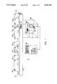
- FIG. 1illustrates, in perspective, the physical rendering of the detection system of the invention in relation to a parcel stream showing various detectable anomalies
- FIG. 2illustrates, in block diagram form, the subject detection system
- FIG. 3illustrates, in block diagram form, a more detailed rendering of the subject detection system
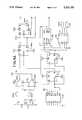
- FIG. 4provides a schematic of the digital processing stage of the subject invention.
- FIG. 1illustrates a detector A as interfaced with a stream of items or parcels B.
- parcel sorting or mail sortingutilizes a conveyor such as illustrated by conveyor 10.
- the conveyor 10moves parcels, illustrated as parcels 12a-12g in a stream as illustrated by direction d.
- Relative placement of the parcels 12have been chosen to illustrate several, representative orientations to be expected during a sorting operation.
- Parcels 12a and 12billustrate a possible orientation of "doubles" that is not easily identified in earlier systems. Any orientation involving two abutting parcels such as illustrated by 12a and 12b is referred to as a "double.” In this case, both 12a and 12b are similarly sized. However, there is only a partial obfuscation or masking of the indicia on parcel 12b by parcel 129. This orientation would be difficult to detect with conventional thickness gauges.
- Parcels 12c and 12dillustrate another situation of a doubles.
- the parcel 12cis substantially smaller than the parcel 12d.
- the 12cis still large enough to mask a portion of the indicia on12d, such as address portion 16 thereof. It may be noted from these parcelsthat certain earlier systems, such as systems which attempt to gauge the thickness of a parcel, would be ineffective with such relatively sized items. It may also be appreciated that such relative sizing would also allow total obfuscation of the smaller parcel in the event the parcels 12dand 12e where interchanged in the illustration.
- Parcels 12e and 12fillustrate a case wherein two parcels are of generally equivalent dimension, and wherein a first parcel 12e masks, virtually in its entirety, second parcel 12f. With this relative orientation, any indicia disposed on the face of 12f would not be available for viewing.
- Parcel 12gillustrates a single parcel traveling as is desired during the operation. This single parcel orientation facilitates viewing of indicia on its face, such as that address portion illustrated at 14. Unobstructed viewing is desirable to facilitate reading by optical character recognition (“OCR”) devices, human operators, bar code readers, and the like. It is also desirable for imprinting of indicia thereon.
- OCRoptical character recognition
- FIG. 1also illustrates a detector head 20 which is affixed to the conveyor10 via suitable mounting brackets (see FIG. 2).
- a base portion 24 of the conveyor 10is provided with an aperture 26 over which the parcels 12 pass.
- the aperture 26hasgenerally rectangular dimensions with a width relative to direction d of about 0.25 inch. It is desirable to provide some degree of protection fromdirt, loose particles, and the like for the detector head. This may be accomplished with an air knife.
- the apertureis also suitably covered with a glass cover plate (not shown) which is flush with the base portion 24 so as to provide a relatively smooth path for travel of the parcels 12.
- the coveris glass in the preferred embodiment, it will be appreciated that any substantially transparent material, such as plastic, quartz, or sapphire may be suitably implemented. However, it is desirable to utilize a substance which is resistant to scratching or marring to minimize image degradation or distortion during continuous use.
- a lighting array 28 and a lens 30Disposed within the detector head 20 is a lighting array 28 and a lens 30. Both the lighting array 28 and lens 30 are mutually oriented relative to the aperture 26 so as to allow specular illumination of parcels 12 as theypass over aperture 26 and image capture of such illuminated parcels by lens30.
- Images captured by lens 30are communicated to a CCD array 34.
- imageis defined as an indicia representative of a recognizable physical characteristic of a parcel or parcels.
- the CCD array 34is comprised of a line scan sensor. Typical of such a line scan sensor is Model IL-C3 TURBO SENSORTM obtained from Dalsa Inc. of Waterloo, Ontario Canada. Briefly, this line scan sensor allows selective 128, 256, 512 or 1728 pixel capture. Each pixel is approximately 14 ⁇ m , in size, providing a photosensitive area of a196 ⁇ m and a 1:1 height-to-width aspect ratio. In the preferred embodiment, the system utilizes the sensor in the 256 or 512 line scan mode.
- the lighting array 28is suitably comprised of various structured lighting sources. These include incandescent, fluorescent, high intensity halogen bulbs, monochromatic and polychromatic lighting emitting diode (“LED”) devices, as well as laser diode sources. While all of these sources are suitable for adequate illumination and reliable image capture, solid stateLED arrays are particularly advantageous. LEDs provide for minimal variation and emitted light, substantially long life, and ease in controllability.
- the chosen CCD sensorprovides very high output data rates up to 30 MHz peroutput for an effective rate up to 60 MHz.
- the CCD array 34 of the preferred embodimentadvantageously provides both the speed and resolutionnecessary for processing a rapid stream of parcels with high reliability. ##EQU1##
- the line scan speedbecomes 58,593.75 Mhz/pixel. This rate is within the definition of "high-speed" in the scan art.
- the processor controlleradvantageously provides a user interface, as particularly illustrated by several representative indicatorportions illustrated on the face thereof.
- FIG. 2a more detailed description of the system of FIG. 1 is provided.
- the figureillustrates a zip code printer 40 and OCR reader 42 disposed adjacent to the conveyor 10.
- parcels traveling along direction dare suitably scanned in the OCR reader 42 and imprinted with a suitable zip code indicia at zip code printer 40.
- progress of the parcelsis then made to aseries of machine process bins 44 for further manipulation.
- the detector head 20is illustrated. It is secured to the conveyor 10 via mounting brackets 50. Images which are captured from the line scan CCD 34 (FIG. 1), are communicated to a processing electronics module 52 which will be detailed below in connection with FIG. 4.
- the processing electronics module 52works in concert with a software/firmwaremodule 54 and a detector user interface 56.
- the detector user interface 56communicates signals adapted for print control, sort control, and the like to an external data processing device 60.
- the external data processing device 60suitably includes machine control functions unit 62, an installed user interface unit 64, and a machine control software unit 66.
- FIG. 3a more detailed block diagram of the subject system is provided.
- Components of the detector head 20are illustrated as a light source portion 20a and an imaging stage portion 20b.
- the light source portion 20aincludes the lighting array 28, as well as a lighting power control 70 to facilitate selective enablement, intensity, control, and the like. Such lighting controls are commonly available and well within the understanding of one of ordinary skill in the art.
- the imaging stage 20bincludes the lens 30, as well as the line scan CCD 34.
- FIG. 3Also illustrated in FIG. 3 is a glass cover plane 72, noted earlier, which is secured within the aperture 26 (FIGS. 1 and 2).
- the line scan CCD 34is disposed generally perpendicular to the direction dof parcel flow. When so oriented, the CCD 34 will output an analog signal which includes pulse indicia representative of a number of transitions associated with overlapped or partially overlapped parcels. This analog signal from CCD 34 is communicated for analog stage processing at processing stage 78.
- the analog stage 74provides an output signal to a digital stage 76, as well as communicating an output to a processing stage 78.
- Processing stage 78communicates processed data to the external data processing device 60 via an interface 80 for post-processing activity.
- the illustration of FIG. 3also includes advantageous self test circuity 88.
- the self test circuitry 88includes a calibration LED 90 which has an optical path to CCD 34.
- a pulse timing circuit 92is in data communication with the above-described digital stage 76.
- a logic decode subsystem 94is in data communication with pulse timing circuit 92,processing stage 78, as well as external data processing unit 60.
- FIG. 3also illustrates a system power module 96 which evidences +15 volts and +5 volts power, obtained from 110 volts AC, as is utilized by the power supply and components of the preferred embodiment. It will be appreciated that this power supply is illustrated only for purposes of thepreferred embodiment. The particular voltage requirements are dependent on the actual components chosen to fabricate the device, as well as the poweravailable at a particular location. Fabrication of such power supplies is well known and suitable systems are readily available on the market.
- FIG. 4a schematic detailing the digital and analog processing referred to above is provided.
- an analog signal resultant from the line scan CCD 34is provided to terminals 100a and 100b.
- These terminalsfeed operational amplifiers (“OP-AMPS”) 102a and 102b, respectively.
- OP-AMPSoperational amplifiers
- Biasing and feedback for each of the OP-AMP, as well as various support circuitryhave been provided in connection withthe preferred embodiment. However, it will be appreciated that many such variations and support structure are readily utilizable in connection withaccomplishing the subject structure.
- the mutual orientation of the operational amplifiers 102provides a means by which the analog signal is changed to pulse data by virtue of the relative saturation between of the inputs thereto.
- Resultant pulse informationis provided to a ripple counter 102 fabricated from a series of D flip-flops 104a-104e. Accordingly, the five ripple counters facilitate pulse counting to a level of 2 5 .
- the four most significantdigits of the ripple counter 102are formed from the outputs of D flip-flops 104a-104e. Each of these outputs are advantageously provided toa light emitting diode 106b-106e, respectively, to facilitate a visual indicia of operation.
- LEDsmay also be provided to the outputs of flip-flops 104a and 104b, the rapidity with which the least significant digits of the ripple counter 104 move would render any visual significanceto be negligible. Further, timings thereof are such that the outputs do undepresent overlap conditions as will be seen below.
- Clocking for the ripple counteris suitably provided by an oscillator 110, the output of which is also latched as a Q output from D flip-flop 112.
- the compliment of the output Q ("Q'"), of flip-flop 112is communicated toanother D flip-flop 104. Its output is communicated to a 74LS56/74LS193 combination 120, 122 which forms a divider, by a multiple of 200, when configured as illustrated.
- the compliment output Q' of flip-flop 114is communicated to a DS0026CN IC, 118 to form an output at terminal 132a, 132b.
- the latter stage of the dividerformed from the 74LS193 synchronous up/down counter, is communicated to a low power Shottky dual monostable multi-vibrator Schmitt trigger 124.
- the Schmitt trigger 124form a clock input for D flip-flops 104b-104e, detailed above.
- the signalis also provided to a second DS0026 CN IC, 128 to form an output at terminal 130.
- the anodes of diodes 106b-106eprovide a signal representative of a particular number of envelopes deemed to have been detected by the system. More particularly, the presence of a first envelope is represented by a signal at terminal 126a, the presence of a second envelope evidenced by a signal at 126b, the presence of a third envelope evidenced by a signal at 126c, and the presence of a fourth envelope evidenced by a signal at terminal 126d. It will be appreciated that additional stages may be cascaded to the ripple counter 102 providingadditional indicia relative to further envelopes. However, four is generally significant to detect multiples associated with common sorting concerns.
Landscapes
- Physics & Mathematics (AREA)
- General Physics & Mathematics (AREA)
- Engineering & Computer Science (AREA)
- Theoretical Computer Science (AREA)
- Sorting Of Articles (AREA)
- Geophysics And Detection Of Objects (AREA)
Abstract
Description
Claims (27)
Priority Applications (5)
| Application Number | Priority Date | Filing Date | Title |
|---|---|---|---|
| US08/008,746US5331151A (en) | 1993-01-25 | 1993-01-25 | Multiple envelope detector |
| EP94922159AEP0680603A4 (en) | 1993-01-25 | 1993-08-19 | Multiple envelope detector. |
| AU50865/93AAU5086593A (en) | 1993-01-25 | 1993-08-19 | Multiple envelope detector |
| JP6516978AJPH08506196A (en) | 1993-01-25 | 1993-08-19 | Multi-envelope detector |
| PCT/US1993/007897WO1994017387A1 (en) | 1993-01-25 | 1993-08-19 | Multiple envelope detector |
Applications Claiming Priority (1)
| Application Number | Priority Date | Filing Date | Title |
|---|---|---|---|
| US08/008,746US5331151A (en) | 1993-01-25 | 1993-01-25 | Multiple envelope detector |
Publications (1)
| Publication Number | Publication Date |
|---|---|
| US5331151Atrue US5331151A (en) | 1994-07-19 |
Family
ID=21733421
Family Applications (1)
| Application Number | Title | Priority Date | Filing Date |
|---|---|---|---|
| US08/008,746Expired - LifetimeUS5331151A (en) | 1993-01-25 | 1993-01-25 | Multiple envelope detector |
Country Status (5)
| Country | Link |
|---|---|
| US (1) | US5331151A (en) |
| EP (1) | EP0680603A4 (en) |
| JP (1) | JPH08506196A (en) |
| AU (1) | AU5086593A (en) |
| WO (1) | WO1994017387A1 (en) |
Cited By (28)
| Publication number | Priority date | Publication date | Assignee | Title |
|---|---|---|---|---|
| US5805279A (en)* | 1996-01-11 | 1998-09-08 | Alltrista Corporation | Method and apparatus for illuminating and imaging a can end coated with sealing material |
| EP0813913A3 (en)* | 1996-06-22 | 1999-01-20 | Siemens Aktiengesellschaft | Method for recognizing overlapping between flat mail objects |
| FR2783442A1 (en)* | 1998-09-21 | 2000-03-24 | Poste | Postal packet multiple packet separator method having multiple containers holding packets vertical and lower V-shaped section with lower conveyor belt section base area detecting/separating packets. |
| US6236735B1 (en) | 1995-04-10 | 2001-05-22 | United Parcel Service Of America, Inc. | Two camera system for locating and storing indicia on conveyed items |
| US6314193B1 (en)* | 1998-01-15 | 2001-11-06 | International Business Machines Corporation | Method and device for localizing and detecting plastic strips and window areas on mail |
| US6384421B1 (en) | 1999-10-07 | 2002-05-07 | Logical Systems Incorporated | Vision system for industrial parts |
| US20030132572A1 (en)* | 2001-12-03 | 2003-07-17 | Andre Rompe | Multiples detect apparatus and method |
| US20050001035A1 (en)* | 2003-05-12 | 2005-01-06 | Thomas Hawley | Picture taking optical reader |
| US20050167504A1 (en)* | 1997-10-17 | 2005-08-04 | Meier Timothy P. | Bar code reading device having image processing mode |
| US6942151B2 (en) | 2001-05-15 | 2005-09-13 | Welch Allyn Data Collection, Inc. | Optical reader having decoding and image capturing functionality |
| WO2006016186A1 (en)* | 2004-08-12 | 2006-02-16 | Wessex Technology Opto-Electronic Products Ltd | Method for double feed detection |
| US7111787B2 (en) | 2001-05-15 | 2006-09-26 | Hand Held Products, Inc. | Multimode image capturing and decoding optical reader |
| US20060249438A1 (en)* | 2003-05-02 | 2006-11-09 | Siemens Aktiengesellschaft | Method and device for orienting flat items of mail towards a narrow edge |
| US20060269102A1 (en)* | 2005-05-02 | 2006-11-30 | Carpenter Michael D | Method and apparatus for detecting doubles in a singulated stream of flat articles |
| US7287697B2 (en) | 2001-07-13 | 2007-10-30 | Hand Held Products, Inc. | Optical reader having a color imager |
| US7293712B2 (en) | 2004-10-05 | 2007-11-13 | Hand Held Products, Inc. | System and method to automatically discriminate between a signature and a dataform |
| US20080036139A1 (en)* | 2006-08-14 | 2008-02-14 | Gregory Reyner | Non-contact sensing system |
| US20080291439A1 (en)* | 2007-05-24 | 2008-11-27 | Applied Vision Company, Llc | Apparatus and methods for container inspection |
| US20080291440A1 (en)* | 2007-05-24 | 2008-11-27 | Applied Vision Company, Llc | Apparatus and methods for container inspection |
| US20080292178A1 (en)* | 2007-05-24 | 2008-11-27 | Applied Vision Company, Llc | Apparatus and methods for container inspection |
| US20090107896A1 (en)* | 2007-10-30 | 2009-04-30 | Logical Systems Incorporated | Air separator conveyor and vision system |
| US20110052362A1 (en)* | 2009-04-28 | 2011-03-03 | Solystic | Method of detecting open mailpieces such as non-wrapped magazines |
| DE102010014105A1 (en)* | 2010-04-07 | 2011-10-13 | Siemens Aktiengesellschaft | Method and device for measuring objects during transport |
| US8381984B2 (en) | 2010-03-31 | 2013-02-26 | Hand Held Products, Inc. | System operative for processing frame having representation of substrate |
| US8657200B2 (en) | 2011-06-20 | 2014-02-25 | Metrologic Instruments, Inc. | Indicia reading terminal with color frame processing |
| US20150251227A1 (en)* | 2014-03-10 | 2015-09-10 | Cognex Corporation | Air flow mechanism for image capture and vision systems |
| US9298964B2 (en) | 2010-03-31 | 2016-03-29 | Hand Held Products, Inc. | Imaging terminal, imaging sensor to determine document orientation based on bar code orientation and methods for operating the same |
| US10049250B2 (en) | 2010-03-31 | 2018-08-14 | Hand Held Products, Inc | Document decoding system and method for improved decoding performance of indicia reading terminal |
Families Citing this family (3)
| Publication number | Priority date | Publication date | Assignee | Title |
|---|---|---|---|---|
| CA2401401A1 (en)* | 2001-11-14 | 2003-05-14 | Omron Canada Inc. | A method and system for double feed detection |
| CA2361969A1 (en) | 2001-11-14 | 2003-05-14 | Omron Canada Inc. | A method and system for double feed detection in a letter sorting apparatus |
| FR2842127A1 (en)* | 2002-07-11 | 2004-01-16 | Solystic | METHOD FOR DETECTING MULTIPLE SOCKETS IN A POSTAL SORTING INSTALLATION |
Citations (3)
| Publication number | Priority date | Publication date | Assignee | Title |
|---|---|---|---|---|
| US4481667A (en)* | 1981-12-21 | 1984-11-06 | Autronics Corporation | Item counting apparatus |
| US4807263A (en)* | 1986-03-27 | 1989-02-21 | Tokyo Kikai Seisakusho, Ltd. | Counter of objects being transported |
| US5040196A (en)* | 1987-10-20 | 1991-08-13 | Woodward William H | Stack counting instrument |
Family Cites Families (3)
| Publication number | Priority date | Publication date | Assignee | Title |
|---|---|---|---|---|
| FR2057309A5 (en)* | 1969-08-11 | 1971-05-21 | Robotron Veb K | |
| FR2546083B1 (en)* | 1983-05-20 | 1986-04-18 | Hotchkiss Brandt Sogeme | DEVICE FOR DETECTING MULTIPLE OBJECT SOCKETS |
| US4650991A (en)* | 1983-07-01 | 1987-03-17 | De La Rue Systems Limited | Method and apparatus for sensing sheets |
- 1993
- 1993-01-25USUS08/008,746patent/US5331151A/ennot_activeExpired - Lifetime
- 1993-08-19WOPCT/US1993/007897patent/WO1994017387A1/ennot_activeApplication Discontinuation
- 1993-08-19AUAU50865/93Apatent/AU5086593A/ennot_activeAbandoned
- 1993-08-19JPJP6516978Apatent/JPH08506196A/enactivePending
- 1993-08-19EPEP94922159Apatent/EP0680603A4/ennot_activeWithdrawn
Patent Citations (3)
| Publication number | Priority date | Publication date | Assignee | Title |
|---|---|---|---|---|
| US4481667A (en)* | 1981-12-21 | 1984-11-06 | Autronics Corporation | Item counting apparatus |
| US4807263A (en)* | 1986-03-27 | 1989-02-21 | Tokyo Kikai Seisakusho, Ltd. | Counter of objects being transported |
| US5040196A (en)* | 1987-10-20 | 1991-08-13 | Woodward William H | Stack counting instrument |
Non-Patent Citations (8)
| Title |
|---|
| Blackburn, J. "Sets, To Separate or Not to Separate", Print. Ind., vol. 86 Nov. 1987. |
| Blackburn, J. Sets, To Separate or Not to Separate , Print. Ind., vol. 86 Nov. 1987.* |
| Goderis, K. et al., "AM at the Hour of the Third Generation," pp. 25-27, May 1983. |
| Goderis, K. et al., AM at the Hour of the Third Generation, pp. 25 27, May 1983.* |
| Hargreaves, T., "Counting-Then, Now And in the Future", Printing Monthly, May 1989. |
| Hargreaves, T., Counting Then, Now And in the Future , Printing Monthly, May 1989.* |
| Royse, "Blanket Press Launch From SOAG", Lithoweek, Aug. 1990. |
| Royse, Blanket Press Launch From SOAG , Lithoweek, Aug. 1990.* |
Cited By (65)
| Publication number | Priority date | Publication date | Assignee | Title |
|---|---|---|---|---|
| US6236735B1 (en) | 1995-04-10 | 2001-05-22 | United Parcel Service Of America, Inc. | Two camera system for locating and storing indicia on conveyed items |
| US5805279A (en)* | 1996-01-11 | 1998-09-08 | Alltrista Corporation | Method and apparatus for illuminating and imaging a can end coated with sealing material |
| EP0813913A3 (en)* | 1996-06-22 | 1999-01-20 | Siemens Aktiengesellschaft | Method for recognizing overlapping between flat mail objects |
| US7222789B2 (en) | 1997-10-17 | 2007-05-29 | Hand Held Products, Inc. | Bar code reading device having image processing mode |
| US20050167504A1 (en)* | 1997-10-17 | 2005-08-04 | Meier Timothy P. | Bar code reading device having image processing mode |
| US7841532B2 (en) | 1997-10-17 | 2010-11-30 | Hand Held Products, Inc. | Bar code reading device having image processing mode |
| US7523866B2 (en) | 1997-10-17 | 2009-04-28 | Hand Held Products, Inc. | Bar code reading device having image processing mode |
| US8282006B2 (en) | 1997-10-17 | 2012-10-09 | Hand Held Products, Inc. | Imaging device operative for image processing |
| US6314193B1 (en)* | 1998-01-15 | 2001-11-06 | International Business Machines Corporation | Method and device for localizing and detecting plastic strips and window areas on mail |
| FR2783442A1 (en)* | 1998-09-21 | 2000-03-24 | Poste | Postal packet multiple packet separator method having multiple containers holding packets vertical and lower V-shaped section with lower conveyor belt section base area detecting/separating packets. |
| WO2000016915A1 (en)* | 1998-09-21 | 2000-03-30 | La Poste | Method for detecting multiple presence of objects in a sorting machine |
| US6384421B1 (en) | 1999-10-07 | 2002-05-07 | Logical Systems Incorporated | Vision system for industrial parts |
| US6784447B2 (en) | 1999-10-07 | 2004-08-31 | Logical Systems, Inc. | Vision system with reflective device for industrial parts |
| US20020125450A1 (en)* | 1999-10-07 | 2002-09-12 | Logical Systems Incorporated | Vision system with reflective device for industrial parts |
| US8439262B2 (en) | 2001-05-15 | 2013-05-14 | Hand Held Products, Inc. | Image capture apparatus and method |
| US7111787B2 (en) | 2001-05-15 | 2006-09-26 | Hand Held Products, Inc. | Multimode image capturing and decoding optical reader |
| US6942151B2 (en) | 2001-05-15 | 2005-09-13 | Welch Allyn Data Collection, Inc. | Optical reader having decoding and image capturing functionality |
| US8794522B2 (en) | 2001-05-15 | 2014-08-05 | Hand Held Products, Inc. | Image capture apparatus and method |
| US7543747B2 (en) | 2001-05-15 | 2009-06-09 | Hand Held Products, Inc. | Image capture apparatus and method |
| US8528818B2 (en) | 2001-07-13 | 2013-09-10 | Hand Held Products, Inc. | Optical reader having an imager |
| US7287697B2 (en) | 2001-07-13 | 2007-10-30 | Hand Held Products, Inc. | Optical reader having a color imager |
| US8292180B2 (en) | 2001-07-13 | 2012-10-23 | Hand Held Products, Inc. | Optical reader having an imager |
| US7413127B2 (en) | 2001-07-13 | 2008-08-19 | Hand Held Products, Inc. | Optical reader for classifying an image |
| US7686222B2 (en) | 2001-07-13 | 2010-03-30 | Hand Held Products, Inc. | Optical reader having a color imager |
| EP1472165A4 (en)* | 2001-12-03 | 2005-03-02 | Siemens Ag | DEVICE AND METHOD FOR DETECTING MULTIPLE |
| US6817610B2 (en) | 2001-12-03 | 2004-11-16 | Siemens Aktiengesellschaft | Multiples detect apparatus and method |
| US20030132572A1 (en)* | 2001-12-03 | 2003-07-17 | Andre Rompe | Multiples detect apparatus and method |
| US20060249438A1 (en)* | 2003-05-02 | 2006-11-09 | Siemens Aktiengesellschaft | Method and device for orienting flat items of mail towards a narrow edge |
| US7344016B2 (en)* | 2003-05-02 | 2008-03-18 | Siemens Ag | Method and device for orienting flat items of mail towards a narrow edge |
| US20050001035A1 (en)* | 2003-05-12 | 2005-01-06 | Thomas Hawley | Picture taking optical reader |
| US8789758B2 (en) | 2003-05-12 | 2014-07-29 | Hand Held Products, Inc. | Picture taking reading apparatus |
| US8104686B2 (en) | 2003-05-12 | 2012-01-31 | Hand Held Products, Inc. | Apparatus comprising image sensor |
| US7637430B2 (en) | 2003-05-12 | 2009-12-29 | Hand Held Products, Inc. | Picture taking optical reader |
| US8218813B2 (en) | 2004-08-12 | 2012-07-10 | Wessex Technology Opto-Electronic Products Ltd. | Method for double feed detection |
| WO2006016186A1 (en)* | 2004-08-12 | 2006-02-16 | Wessex Technology Opto-Electronic Products Ltd | Method for double feed detection |
| US20090051108A1 (en)* | 2004-08-12 | 2009-02-26 | Wessex Technology Opto-Electronic Products Ltd | Method for double feed detection |
| US8196842B2 (en) | 2004-10-05 | 2012-06-12 | Hand Held Products, Inc. | System and method to automatically discriminate between different data types |
| US9317763B2 (en) | 2004-10-05 | 2016-04-19 | Hand Held Products, Inc. | System and method to automatically discriminate between different data types |
| US8636224B2 (en) | 2004-10-05 | 2014-01-28 | Hand Held Products, Inc. | System and method to automatically discriminate between different data types |
| US7922088B2 (en) | 2004-10-05 | 2011-04-12 | Hand Held Products, Inc. | System and method to automatically discriminate between different data types |
| US7293712B2 (en) | 2004-10-05 | 2007-11-13 | Hand Held Products, Inc. | System and method to automatically discriminate between a signature and a dataform |
| US7809158B2 (en) | 2005-05-02 | 2010-10-05 | Siemens Industry, Inc. | Method and apparatus for detecting doubles in a singulated stream of flat articles |
| US20060269102A1 (en)* | 2005-05-02 | 2006-11-30 | Carpenter Michael D | Method and apparatus for detecting doubles in a singulated stream of flat articles |
| US20080036139A1 (en)* | 2006-08-14 | 2008-02-14 | Gregory Reyner | Non-contact sensing system |
| US8014586B2 (en) | 2007-05-24 | 2011-09-06 | Applied Vision Corporation | Apparatus and methods for container inspection |
| US7667836B2 (en) | 2007-05-24 | 2010-02-23 | Applied Vision Company, Llc | Apparatus and methods for container inspection |
| US20080291439A1 (en)* | 2007-05-24 | 2008-11-27 | Applied Vision Company, Llc | Apparatus and methods for container inspection |
| US20080292178A1 (en)* | 2007-05-24 | 2008-11-27 | Applied Vision Company, Llc | Apparatus and methods for container inspection |
| US7684034B2 (en) | 2007-05-24 | 2010-03-23 | Applied Vision Company, Llc | Apparatus and methods for container inspection |
| US20080291440A1 (en)* | 2007-05-24 | 2008-11-27 | Applied Vision Company, Llc | Apparatus and methods for container inspection |
| US20090107896A1 (en)* | 2007-10-30 | 2009-04-30 | Logical Systems Incorporated | Air separator conveyor and vision system |
| US7800009B2 (en) | 2007-10-30 | 2010-09-21 | Logical Systems Incorporated | Air separator conveyor and vision system |
| US20110052362A1 (en)* | 2009-04-28 | 2011-03-03 | Solystic | Method of detecting open mailpieces such as non-wrapped magazines |
| US8371581B2 (en)* | 2009-04-28 | 2013-02-12 | Solystic | Method of detecting open mailpieces such as non-wrapped magazines |
| US9785815B2 (en) | 2010-03-31 | 2017-10-10 | Hand Held Products, Inc. | Imaging terminal, imaging sensor to determine document orientation based on bar code orientation and methods for operating the same |
| US8381984B2 (en) | 2010-03-31 | 2013-02-26 | Hand Held Products, Inc. | System operative for processing frame having representation of substrate |
| US10331929B2 (en) | 2010-03-31 | 2019-06-25 | Hand Held Products, Inc. | Imaging terminal, imaging sensor to determine document orientation based on bar code orientation and methods for operating the same |
| US10049250B2 (en) | 2010-03-31 | 2018-08-14 | Hand Held Products, Inc | Document decoding system and method for improved decoding performance of indicia reading terminal |
| US9298964B2 (en) | 2010-03-31 | 2016-03-29 | Hand Held Products, Inc. | Imaging terminal, imaging sensor to determine document orientation based on bar code orientation and methods for operating the same |
| DE102010014105A1 (en)* | 2010-04-07 | 2011-10-13 | Siemens Aktiengesellschaft | Method and device for measuring objects during transport |
| WO2011124583A1 (en) | 2010-04-07 | 2011-10-13 | Siemens Aktiengesellschaft | Method and device for the controlled transport of multiple objects |
| US8657200B2 (en) | 2011-06-20 | 2014-02-25 | Metrologic Instruments, Inc. | Indicia reading terminal with color frame processing |
| US8910875B2 (en) | 2011-06-20 | 2014-12-16 | Metrologic Instruments, Inc. | Indicia reading terminal with color frame processing |
| US9908158B2 (en)* | 2014-03-10 | 2018-03-06 | Ametek, Inc. | Air flow mechanism for image capture and vision systems |
| US20150251227A1 (en)* | 2014-03-10 | 2015-09-10 | Cognex Corporation | Air flow mechanism for image capture and vision systems |
Also Published As
| Publication number | Publication date |
|---|---|
| WO1994017387A1 (en) | 1994-08-04 |
| JPH08506196A (en) | 1996-07-02 |
| AU5086593A (en) | 1994-08-15 |
| EP0680603A1 (en) | 1995-11-08 |
| EP0680603A4 (en) | 1997-09-03 |
Similar Documents
| Publication | Publication Date | Title |
|---|---|---|
| US5331151A (en) | Multiple envelope detector | |
| JP3207419B2 (en) | Parcel distribution method | |
| US6817610B2 (en) | Multiples detect apparatus and method | |
| US5943432A (en) | Postage due detection system | |
| US7809158B2 (en) | Method and apparatus for detecting doubles in a singulated stream of flat articles | |
| US5431288A (en) | Mail sorting apparatus | |
| JPS63207270A (en) | reading processing unit | |
| EP0134996B1 (en) | An apparatus for detecting the flatness of a paper sheet | |
| JP4871869B2 (en) | Duplicate feed detection method | |
| GB1590912A (en) | Device for checking envelopes for enclosed documents | |
| US20030115071A1 (en) | Method of operating an image-based document processing system and an apparatus therefor | |
| CA1178711A (en) | Apparatus and process for scanning and analyzing mail address information | |
| JPH01217687A (en) | optical character reader | |
| JP3660404B2 (en) | Address area detecting device, address reading device, sorting machine, and address reading method | |
| JPS59216677A (en) | Surface and back surface judge apparatus of paper sheets | |
| JPH04326187A (en) | Mail address reading device | |
| EP0105061A1 (en) | Luminescent address bar codes | |
| US20080012981A1 (en) | Mail processing system with dual camera assembly | |
| JP3321313B2 (en) | Postage mark detection device, postage mark detection method, and mail processing device | |
| JPS59149578A (en) | Price stamp | |
| JP3654959B2 (en) | Counting device and article sorting device | |
| JP2647184B2 (en) | Mail handling equipment | |
| JPH11226517A (en) | Barcode sorting device | |
| JPS59180680A (en) | Detector of light emitting substance | |
| JPH0810711A (en) | Charge mark detection device |
Legal Events
| Date | Code | Title | Description |
|---|---|---|---|
| AS | Assignment | Owner name:PRESSCO TECHNOLOGY, INC., OHIO Free format text:ASSIGNMENT OF ASSIGNORS INTEREST.;ASSIGNORS:COCHRAN, DON W.;TRINER, JAMES E.;REEL/FRAME:006407/0919 Effective date:19930125 | |
| STCF | Information on status: patent grant | Free format text:PATENTED CASE | |
| FPAY | Fee payment | Year of fee payment:4 | |
| AS | Assignment | Owner name:KEYBANK NATIONAL ASSOCIATION, OHIO Free format text:SECURITY AGREEMENT;ASSIGNOR:PRESSCO TECHNOLOGY, INC.;REEL/FRAME:009605/0849 Effective date:19980930 | |
| FPAY | Fee payment | Year of fee payment:8 | |
| AS | Assignment | Owner name:SIDEL, INC., GEORGIA Free format text:SECURITY INTEREST;ASSIGNOR:PRESSCO TECHNOLOGY, INC.;REEL/FRAME:013852/0128 Effective date:20030630 | |
| AS | Assignment | Owner name:PRESSCO TECHNOLOGY INC., OHIO Free format text:RE-ASSIGNMENT OF PATENTS AGREEMENT;ASSIGNOR:KEYBANK NATIONAL ASSOCIATION;REEL/FRAME:015756/0063 Effective date:20030630 | |
| FPAY | Fee payment | Year of fee payment:12 |