US5330528A - Vascular surgical devices - Google Patents
Vascular surgical devicesDownload PDFInfo
- Publication number
- US5330528A US5330528AUS07/859,450US85945092AUS5330528AUS 5330528 AUS5330528 AUS 5330528AUS 85945092 AUS85945092 AUS 85945092AUS 5330528 AUS5330528 AUS 5330528A
- Authority
- US
- United States
- Prior art keywords
- chamber
- wall
- annular
- body member
- portions
- Prior art date
- Legal status (The legal status is an assumption and is not a legal conclusion. Google has not performed a legal analysis and makes no representation as to the accuracy of the status listed.)
- Expired - Fee Related
Links
- 230000002792vascularEffects0.000titledescription2
- 210000001124body fluidAnatomy0.000claimsabstractdescription13
- 239000010839body fluidSubstances0.000claimsabstractdescription13
- 239000000523sampleSubstances0.000claimsabstractdescription12
- 238000005070samplingMethods0.000claimsabstractdescription8
- 238000003780insertionMethods0.000claimsabstractdescription7
- 230000037431insertionEffects0.000claimsabstractdescription7
- 238000012544monitoring processMethods0.000claimsabstractdescription6
- 239000000463materialSubstances0.000claimsdescription14
- 238000004891communicationMethods0.000claimsdescription6
- 238000009877renderingMethods0.000claimsdescription6
- 239000007787solidSubstances0.000claimsdescription3
- 208000007474aortic aneurysmDiseases0.000abstractdescription5
- 210000001105femoral arteryAnatomy0.000abstractdescription3
- 210000004204blood vesselAnatomy0.000abstractdescription2
- 238000006467substitution reactionMethods0.000abstractdescription2
- 206010002329AneurysmDiseases0.000description15
- 238000001356surgical procedureMethods0.000description11
- 210000000709aortaAnatomy0.000description9
- 239000012530fluidSubstances0.000description9
- 239000008280bloodSubstances0.000description6
- 210000004369bloodAnatomy0.000description6
- 210000001367arteryAnatomy0.000description5
- 230000035939shockEffects0.000description5
- 230000017531blood circulationEffects0.000description4
- 230000006378damageEffects0.000description4
- 238000000034methodMethods0.000description4
- 208000002223abdominal aortic aneurysmDiseases0.000description3
- 238000010276constructionMethods0.000description3
- 238000012986modificationMethods0.000description3
- 230000004048modificationEffects0.000description3
- 230000008439repair processEffects0.000description3
- 238000011144upstream manufacturingMethods0.000description3
- 208000004717Ruptured AneurysmDiseases0.000description2
- 208000007536ThrombosisDiseases0.000description2
- 208000027418Wounds and injuryDiseases0.000description2
- 230000008901benefitEffects0.000description2
- 230000000903blocking effectEffects0.000description2
- 230000000694effectsEffects0.000description2
- 210000003141lower extremityAnatomy0.000description2
- 230000001575pathological effectEffects0.000description2
- 210000002254renal arteryAnatomy0.000description2
- 210000003270subclavian arteryAnatomy0.000description2
- 210000003462veinAnatomy0.000description2
- 206010067484Adverse reactionDiseases0.000description1
- 201000003126AnuriaDiseases0.000description1
- 206010003210ArteriosclerosisDiseases0.000description1
- 206010005746Blood pressure fluctuationDiseases0.000description1
- 206010010356Congenital anomalyDiseases0.000description1
- 208000018672DilatationDiseases0.000description1
- 206010016717FistulaDiseases0.000description1
- 206010020772HypertensionDiseases0.000description1
- 208000001953HypotensionDiseases0.000description1
- 241000124008MammaliaSpecies0.000description1
- 208000034486Multi-organ failureDiseases0.000description1
- 208000010718Multiple Organ FailureDiseases0.000description1
- 208000001647Renal InsufficiencyDiseases0.000description1
- 201000008982Thoracic Aortic AneurysmDiseases0.000description1
- 230000006838adverse reactionEffects0.000description1
- 230000001668ameliorated effectEffects0.000description1
- 238000004458analytical methodMethods0.000description1
- 238000002583angiographyMethods0.000description1
- 208000011775arteriosclerosis diseaseDiseases0.000description1
- 239000000560biocompatible materialSubstances0.000description1
- 230000015572biosynthetic processEffects0.000description1
- 230000036772blood pressureEffects0.000description1
- 238000009530blood pressure measurementMethods0.000description1
- 210000004556brainAnatomy0.000description1
- 238000012937correctionMethods0.000description1
- 230000007812deficiencyEffects0.000description1
- 230000003111delayed effectEffects0.000description1
- 238000006073displacement reactionMethods0.000description1
- 238000002297emergency surgeryMethods0.000description1
- 230000003890fistulaEffects0.000description1
- 210000002216heartAnatomy0.000description1
- 230000004217heart functionEffects0.000description1
- 238000011065in-situ storageMethods0.000description1
- 208000014674injuryDiseases0.000description1
- 238000005304joiningMethods0.000description1
- 201000006370kidney failureDiseases0.000description1
- 230000003907kidney functionEffects0.000description1
- 230000007774longtermEffects0.000description1
- 208000012866low blood pressureDiseases0.000description1
- 210000004072lungAnatomy0.000description1
- 230000004199lung functionEffects0.000description1
- 238000004519manufacturing processMethods0.000description1
- 238000005259measurementMethods0.000description1
- 230000006371metabolic abnormalityEffects0.000description1
- 208000029744multiple organ dysfunction syndromeDiseases0.000description1
- 208000010125myocardial infarctionDiseases0.000description1
- 210000000056organAnatomy0.000description1
- 210000004197pelvisAnatomy0.000description1
- 230000000149penetrating effectEffects0.000description1
- 229920003023plasticPolymers0.000description1
- 239000004033plasticSubstances0.000description1
- 229920002635polyurethanePolymers0.000description1
- 239000004814polyurethaneSubstances0.000description1
- 239000004800polyvinyl chlorideSubstances0.000description1
- 229920000915polyvinyl chloridePolymers0.000description1
- 238000003825pressingMethods0.000description1
- 230000002685pulmonary effectEffects0.000description1
- 230000000717retained effectEffects0.000description1
- 238000007789sealingMethods0.000description1
- 230000006641stabilisationEffects0.000description1
- 239000000126substanceSubstances0.000description1
- 210000003437tracheaAnatomy0.000description1
- 230000007556vascular defectEffects0.000description1
- 238000007631vascular surgeryMethods0.000description1
Images


Classifications
- A—HUMAN NECESSITIES
- A61—MEDICAL OR VETERINARY SCIENCE; HYGIENE
- A61F—FILTERS IMPLANTABLE INTO BLOOD VESSELS; PROSTHESES; DEVICES PROVIDING PATENCY TO, OR PREVENTING COLLAPSING OF, TUBULAR STRUCTURES OF THE BODY, e.g. STENTS; ORTHOPAEDIC, NURSING OR CONTRACEPTIVE DEVICES; FOMENTATION; TREATMENT OR PROTECTION OF EYES OR EARS; BANDAGES, DRESSINGS OR ABSORBENT PADS; FIRST-AID KITS
- A61F2/00—Filters implantable into blood vessels; Prostheses, i.e. artificial substitutes or replacements for parts of the body; Appliances for connecting them with the body; Devices providing patency to, or preventing collapsing of, tubular structures of the body, e.g. stents
- A61F2/02—Prostheses implantable into the body
- A61F2/04—Hollow or tubular parts of organs, e.g. bladders, tracheae, bronchi or bile ducts
- A61F2/06—Blood vessels
- A61F2/07—Stent-grafts
- A—HUMAN NECESSITIES
- A61—MEDICAL OR VETERINARY SCIENCE; HYGIENE
- A61F—FILTERS IMPLANTABLE INTO BLOOD VESSELS; PROSTHESES; DEVICES PROVIDING PATENCY TO, OR PREVENTING COLLAPSING OF, TUBULAR STRUCTURES OF THE BODY, e.g. STENTS; ORTHOPAEDIC, NURSING OR CONTRACEPTIVE DEVICES; FOMENTATION; TREATMENT OR PROTECTION OF EYES OR EARS; BANDAGES, DRESSINGS OR ABSORBENT PADS; FIRST-AID KITS
- A61F2/00—Filters implantable into blood vessels; Prostheses, i.e. artificial substitutes or replacements for parts of the body; Appliances for connecting them with the body; Devices providing patency to, or preventing collapsing of, tubular structures of the body, e.g. stents
- A61F2/95—Instruments specially adapted for placement or removal of stents or stent-grafts
- A61F2/958—Inflatable balloons for placing stents or stent-grafts
- A—HUMAN NECESSITIES
- A61—MEDICAL OR VETERINARY SCIENCE; HYGIENE
- A61F—FILTERS IMPLANTABLE INTO BLOOD VESSELS; PROSTHESES; DEVICES PROVIDING PATENCY TO, OR PREVENTING COLLAPSING OF, TUBULAR STRUCTURES OF THE BODY, e.g. STENTS; ORTHOPAEDIC, NURSING OR CONTRACEPTIVE DEVICES; FOMENTATION; TREATMENT OR PROTECTION OF EYES OR EARS; BANDAGES, DRESSINGS OR ABSORBENT PADS; FIRST-AID KITS
- A61F2/00—Filters implantable into blood vessels; Prostheses, i.e. artificial substitutes or replacements for parts of the body; Appliances for connecting them with the body; Devices providing patency to, or preventing collapsing of, tubular structures of the body, e.g. stents
- A61F2/82—Devices providing patency to, or preventing collapsing of, tubular structures of the body, e.g. stents
- A61F2/86—Stents in a form characterised by the wire-like elements; Stents in the form characterised by a net-like or mesh-like structure
- A61F2/90—Stents in a form characterised by the wire-like elements; Stents in the form characterised by a net-like or mesh-like structure characterised by a net-like or mesh-like structure
- A—HUMAN NECESSITIES
- A61—MEDICAL OR VETERINARY SCIENCE; HYGIENE
- A61F—FILTERS IMPLANTABLE INTO BLOOD VESSELS; PROSTHESES; DEVICES PROVIDING PATENCY TO, OR PREVENTING COLLAPSING OF, TUBULAR STRUCTURES OF THE BODY, e.g. STENTS; ORTHOPAEDIC, NURSING OR CONTRACEPTIVE DEVICES; FOMENTATION; TREATMENT OR PROTECTION OF EYES OR EARS; BANDAGES, DRESSINGS OR ABSORBENT PADS; FIRST-AID KITS
- A61F2/00—Filters implantable into blood vessels; Prostheses, i.e. artificial substitutes or replacements for parts of the body; Appliances for connecting them with the body; Devices providing patency to, or preventing collapsing of, tubular structures of the body, e.g. stents
- A61F2/02—Prostheses implantable into the body
- A61F2/04—Hollow or tubular parts of organs, e.g. bladders, tracheae, bronchi or bile ducts
- A61F2/06—Blood vessels
- A61F2/07—Stent-grafts
- A61F2002/077—Stent-grafts having means to fill the space between stent-graft and aneurysm wall, e.g. a sleeve
- A—HUMAN NECESSITIES
- A61—MEDICAL OR VETERINARY SCIENCE; HYGIENE
- A61F—FILTERS IMPLANTABLE INTO BLOOD VESSELS; PROSTHESES; DEVICES PROVIDING PATENCY TO, OR PREVENTING COLLAPSING OF, TUBULAR STRUCTURES OF THE BODY, e.g. STENTS; ORTHOPAEDIC, NURSING OR CONTRACEPTIVE DEVICES; FOMENTATION; TREATMENT OR PROTECTION OF EYES OR EARS; BANDAGES, DRESSINGS OR ABSORBENT PADS; FIRST-AID KITS
- A61F2250/00—Special features of prostheses classified in groups A61F2/00 - A61F2/26 or A61F2/82 or A61F9/00 or A61F11/00 or subgroups thereof
- A61F2250/0003—Special features of prostheses classified in groups A61F2/00 - A61F2/26 or A61F2/82 or A61F9/00 or A61F11/00 or subgroups thereof having an inflatable pocket filled with fluid, e.g. liquid or gas
Definitions
- the inventionis concerned with improvements in or relating to devices suitable for use in vascular surgery, particularly but not exclusively for use in substitution for or replacement of a damaged or malformed region of vessel or other conduit normally adapted to carry a fluid flow in mammals.
- aneurysmsmay occur at any region of the aorta, those situated below the diaphragm, i.e. the abdominal aortic aneurysms, give the most pressing instances in which urgent surgery should be carried out if the patient is to survive. Nevertheless the general condition of the patient will probably be at a poor level due to deep shock associated with blood loss, anuria and/or low blood pressure.
- the inventionprovides a surgical device suitable for insertion into a body fluid passageway to span a damaged or deformed portion thereof by forming communication between two relatively sound portions of said passageway spaced apart by the intervening damaged or deformed region of the passageway, said device comprising a substantially tubular body portion having open end portions, and an outer sleeve member secured at one end thereof to the body portion adjacent to one of said open end portions and secured at the other end thereof to the body portion adjacent the second of said Open end portions so as to define an annular outer chamber around said body portion, said outer sleeve member being formed from flexible material in order to allow inflation of said annular outer chamber, the body member comprising a tubular wall arrangement adapted to be in an inoperative, flaccid, condition immediately before use, means being provided for rendering the flaccid wall arrangement into a relatively rigid condition when the device is in position for use within the body fluid passageway, means also being provided for the concomitant comprising a tubular wall arrangement adapted to be in an inoperative, flaccid, condition immediately before use
- the inventionprovides, in another of its several aspects, a surgical device suitable for insertion into a body fluid passageway to span a damaged or deformed portion thereof by forming communication between two relatively sound portions of said passageway spaced apart by the intervening damaged or deformed region of the passageway, said device comprising a substantially tubular body portion having open end portions, and an outer sleeve member secured at one end thereof to the body portion adjacent to one of said open end portions and secured at the other end thereof to the body portion adjacent the second of said open end portions so as to define an annular outer chamber around said body portion, said outer sleeve member being formed from flexible material in order to allow inflation of said annular outer chamber, the body member comprising a tubular wall arrangement adapted to be in an inoperative, flaccid, condition immediately before use, means being provided for rendering the flaccid wall arrangement into a relatively rigid condition when the device is in position for use within the body fluid passageway, means also being provided for the concomitant inflation of the annular outer chamber.
- the tubular wall arrangement of the body membercomprises an inner flexible wall portion and an outer, substantially coaxial, wall portion, said wall portions being sealed to each other at end portions thereof to form an annular wall chamber, the means to render the flaccid wall arrangement into a relatively rigid condition comprising inflation means to inflate the annular wall chamber.
- the outer wall portion of the annular wall chamberis common with and shared by the annular outer chamber, forming its inner surface.
- the annular wall chamberis inflated to a pressure higher than that of the annular outer chamber, the pressure in said outer chamber being such that the sleeve member is readily conformable to the contours of the interior surface of the intervening passageway region.
- the monitoring meansmay include a perforated probe projecting into, for example, the blood passing through an artery or vein. Such a probe may conveniently enter the device through a sealed aperture through which also pass inflation tubes leading to the inflatable chamber(s).
- the tubular wall arrangementcomprises an inflatable annular chamber, which is to be inflated to an extent at which it becomes, reasonably rigid, may be prevented from undue distortion or "ballooning" by the provision of ties spanning the annular chamber in a radial manner to link outer and inner wall portions.
- the annular chambercomprises a plurality of interconnected longitudinally arranged inflatable channels, conveniently having intervening plain areas.
- a devicemay be used to form a conduit or a closure for a fistula which may be of a naturally occurring type such as a vascular defect affecting babies where a pre-birth pulmonary by-pass passage fails to close or, alternatively, requires to be kept open for a certain time.
- Other examplesmay be required for use as a result of injury such as a penetrative wound or pathological condition which forms a communication between the trachea and oesophagus or between an artery and a vein.
- a device according to the inventionmay be used to maintain in an open condition a passageway which is at risk from closure due to a pathological condition.
- a device according to the inventionWhile it is often convenient for a device according to the invention to be introduced through the femoral artery, it may be preferred to arrange to introduce the device through the sub-clavian artery.
- Aortic aneurysmsmay occur at any region of the aorta, those above the diaphragm being referred to as thoracic aortic aneurysms and those below being known as abdominal aortic aneurysms, (A.A.A.) .
- Aortic aneurysmsare frequently the result of the effects of arterio-sclerosis and expanded to the point of rupturing by high blood pressure levels.
- the condition of the arteries in patientsis frequently poor and many patients who receive successful operative treatment for the ruptured aneurysm nevertheless die from myocardial infarction, renal or multiple organ failure especially as emergency surgery is usually carried out on a patient who is in a state of deep shock.
- a device according to the inventionmay be used to achieve this aim.
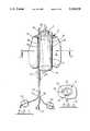
- FIG. 1shows a perspective view partly in section, of the first device in a inflated condition
- FIG. 2is a cross-sectional view on line II--II of FIG. 1, to a slightly smaller scale;
- FIG. 3is a view similar to that of FIG. 2 of a modification of the device
- FIG. 4is a perspective view, partially in section of the device in position in an association with an aortic aneurysm
- FIG. 5shows an alternative constriction of an inner wall portion of the first device
- FIGS. 6 and 7are cross-sectional views of the wall potion as shown in FIG. 5 and in an alternative construction, respectively;
- FIG. 8shows a second example of a device according to the invention.
- FIG. 9is a fragmentary portion of the device of FIG. 8 to an enlarged scale.
- the first devicecomprises an inflatable tubular body 2 having open end portions 4, 6 to provide a passageway therethrough in the direction shown by arrows A.
- the tubular body 2comprises an inner wall portion 8 and an outer wall portion 10 which in the present example are of reinforced polyvinylchloride sheet material, each portion being sealed at said end portions to the other portion to form an annular wall chamber B. It will be understood that other bio-compatible materials may also be utilised.
- a sleeve member 12which in the present example is of polyurethane sheet material, and which together with an outer surface wall portion 10 defines an annular outer chamber, C, as shown in FIGS. 2 and 3.
- the chambersare adapted to be inflated as will be explained below, the modification shown in FIG. 3 including wall tie members 14 adapted to reduce any tendency for distortion of the chamber B by undue ballooning ofthe wall portions 8 and 10.
- the device described in the present exampleis provided with two independent inflation means comprising a supply pipe 16 adapted for use inthe controlled inflation of chamber B and a supply pipe 18 for the controlled inflation of chamber C.
- Monitoring sacs 20, 22allow the user to check the state of inflation from the pipes 16, 18, respectively, although the pipes may be connected to other equipment for accurate measurements of inflation pressures.
- the two pipesare formed into an assembly with a hollow flexible probe 24 comprising a tube having a plurality of sampling apertures 26 at a leadingend thereof which conveniently projects beyond the end portion 4 of the wall portions 8, 10 of chamber B so as to have access to the fluid flowingin the direction of arrow A, upstream of the device.
- Sampling apparatusmaybe attached to the probe 24 at an outer end 28 thereof.
- the probe arrangementmay be used for monitoring blood pressure, taking samples, in angiography, or in association with other sensors.
- FIG. 4shows the device in use in a situation involving an abdominal aorticaneurysm.
- the aorta 30has formed an aneurysm 32 at a region below the renal arteries 34 and above the bifurcation of the aorta at 36.
- the aneurysmhas a tear 38 in the wall thereof and a quantity of thrombus 40 is present within the aneurysm.
- the deviceis in a completely deflated condition in which both chambers B and C are flaccid, taking up the general outline 12 shown in chain dotted lines in FIG. 1.
- An incisionis made in one of the femoral arteries 37 andthe device introduced so as to enter the aneurysm.
- the probe 24acts to support the flaccid chambers during this procedure, the leading end of theprobe acting as a pilot portion. It is convenient if the leading end of theprobe is equipped with sensor means to detect the change in blood pressure velocity or pattern of flow at the region of the entrances to the renal arteries to confirm that the device has been inserted into the required position. However, this is not an essential requirement.
- Chamber Bis inflated and takes up the desired tubular shape as shown in FIG. 4, in which its upper end portion 6 is arranged so that the aorta 30 is substantially or completely blocked by its presence, forcing the blood to flow through the passageway bounded by a tubular wall arrangement which isby now firm and effectively rigid. It will be appreciated that this positioning and blocking is aided by the provision of the shoulder 11 formed at the seam between wall portions 10 and 12.
- chamber CInflation of chamber C through the line 18 meanwhile causes the sleeve member 12 to conform to the shape of the aneurysm allowing for the presence of thrombus.
- tear 38is sealed by the wall portion 12 and the aneurysm generally supported by the inflated chamber C.
- chamber Cis inflated to a pressure level, say, 20-50 mm Hg, less than that required for the chamber B which may be 100-150 mm Hg.
- FIGS. 5 to 7show two alternative forms of construction of chamber B to that illustrated in FIGS. 1 to 4.
- Chamber B'comprises an inner wall 42, and an outer wall 44 that is common to the outer chamber C.
- a series of longitudinally disposed, interconnected passages 46are formed by webs 48 spanning the annular chamber, the passages alone being inflated. It will be observed that the passages 46 are no wider than the intervening areas of wall 42,44.
- the passages 46are defined byintervening solid wall portions 50, the passages 46 comprising the chamber B".
- FIG. 8shows an alternative arrangement which is suitable for use in many circumstances and is particularly suitable where the device is introduced through the sub-clavian artery. It appears that the device illustrated hasthe advantage of minimising the further quantity of blood entering the aneurysm.
- the device shown in FIG. 8comprises a chamber B" of the construction shown in FIGS. 5 and 7 comprising passages 46 and having intervening solid wall portions 50.
- Chamber C'is defined by the outer surface of chamber B" and an outer wall 52 which is flexible but substantially inelastic. It is arranged that chamber B" projects at each end, beyond the chamber C.
- the shape of the wall 52when inflated gives an area of widest diameter at 54 (approximately 55 mm in one example) tapering downwardly to about 30 mm at the area 56.
- the widest diameter at 54is approximately at a level one third of the distance (60 mm) from the leading end 58 of the device to the trailingend 60. It has been found that the formation of the chamber at 54 tends to prevent displacement of the device in use, by normal blood flow.
- FIGS. 8 and 9The inflation and sampling means of FIGS. 8 and 9 will now be described.
- Thiscomprises a supply pipe 62 for inflating the passages 46 of chamber B" and a supply pipe 64 for inflating the chamber C.
- Each pipe 62, 64is provided with a one-way valve 66,68, at a region adjacent a joining zone between the pipes 62 and 64 and extensions 70 and 72 which are connected at their remote ends to a source of CO 2 gas.
- a sampling probe 74theleading end 76 of which projects beyond the leading edge 58 of the device, is also provided with an extension 78, the three extensions being joined by suitable means at 80. It will be understood that the extension 78 is provided at its remote end with a sampling connector to attach to a clinical syringe.
- the devicethus forms an internal by-pass for the aortic blood flow and mayremain in place temporarily at least until the condition of the patient hasstabilised so that conventional surgical techniques may be applied, for example the replacement of the damaged region of the vascular wall by a graft of suitable plastics material. If, however, the patient's condition is such that further surgery is inadvisable, then the device according to the invention may remain in place for a much longer period. Suitable materials will be chosen to permit such an option to be available, that is, materials which do not cause adverse reaction when in situ. Where the device is intended to be effectively permanent, the conduit holding the lines 16 and 18, together with the monitoring probe, may be disconnected at a suitable location.
- a devicewhich includes two inflatable chambers, one inflated to a pressure level such that a reasonably rigid tubular passageway is achieved and the other, surroundingthe first, to assist in sealing and supporting damaged areas. It will be understood that in situations in which it is necessary simply to provide apassageway to replace a section of body conduit, only one tubular chamber need be provided.
Landscapes
- Health & Medical Sciences (AREA)
- Engineering & Computer Science (AREA)
- Biomedical Technology (AREA)
- Cardiology (AREA)
- Oral & Maxillofacial Surgery (AREA)
- Transplantation (AREA)
- Heart & Thoracic Surgery (AREA)
- Vascular Medicine (AREA)
- Life Sciences & Earth Sciences (AREA)
- Animal Behavior & Ethology (AREA)
- General Health & Medical Sciences (AREA)
- Public Health (AREA)
- Veterinary Medicine (AREA)
- Gastroenterology & Hepatology (AREA)
- Pulmonology (AREA)
- Prostheses (AREA)
- Surgical Instruments (AREA)
- Medicines That Contain Protein Lipid Enzymes And Other Medicines (AREA)
- Medicines Containing Material From Animals Or Micro-Organisms (AREA)
- Compounds Of Unknown Constitution (AREA)
- Artificial Filaments (AREA)
- Woven Fabrics (AREA)
- Paper (AREA)
Abstract
Description
Claims (12)
Applications Claiming Priority (3)
| Application Number | Priority Date | Filing Date | Title |
|---|---|---|---|
| GB898927282AGB8927282D0 (en) | 1989-12-01 | 1989-12-01 | Vascular surgical devices |
| GB8927282 | 1989-12-01 | ||
| PCT/GB1990/001871WO1991007927A1 (en) | 1989-12-01 | 1990-11-30 | Vascular surgical devices |
Publications (1)
| Publication Number | Publication Date |
|---|---|
| US5330528Atrue US5330528A (en) | 1994-07-19 |
Family
ID=10667320
Family Applications (1)
| Application Number | Title | Priority Date | Filing Date |
|---|---|---|---|
| US07/859,450Expired - Fee RelatedUS5330528A (en) | 1989-12-01 | 1990-11-30 | Vascular surgical devices |
Country Status (7)
| Country | Link |
|---|---|
| US (1) | US5330528A (en) |
| EP (1) | EP0502905B1 (en) |
| JP (1) | JPH05505115A (en) |
| AT (1) | ATE111332T1 (en) |
| DE (1) | DE69012584T2 (en) |
| GB (1) | GB8927282D0 (en) |
| WO (1) | WO1991007927A1 (en) |
Cited By (134)
| Publication number | Priority date | Publication date | Assignee | Title |
|---|---|---|---|---|
| US5458575A (en)* | 1993-02-16 | 1995-10-17 | Boston Scientific Corp. | Perfusion catheter having a cylindrical array of balloons |
| WO1996014027A1 (en)* | 1994-11-03 | 1996-05-17 | Aeroquip Corporation | Intraluminal stenting graft |
| WO1996020751A1 (en)* | 1994-12-30 | 1996-07-11 | Jaroslav Janacek | Dilation catheter |
| US5554180A (en)* | 1995-07-07 | 1996-09-10 | Aeroquip Corporation | Intraluminal stenting graft |
| US5591228A (en)* | 1995-05-09 | 1997-01-07 | Edoga; John K. | Methods for treating abdominal aortic aneurysms |
| US5613948A (en)* | 1993-11-12 | 1997-03-25 | Cordis Corporation | Annular perfusion balloon catheter |
| US5651767A (en)* | 1994-05-06 | 1997-07-29 | Alfred F. Mann Foundation For Scientific Research | Replaceable catheter system for physiological sensors, stimulating electrodes and/or implantable fluid delivery systems |
| US5662614A (en)* | 1995-05-09 | 1997-09-02 | Edoga; John K. | Balloon expandable universal access sheath |
| US5665117A (en)* | 1995-11-27 | 1997-09-09 | Rhodes; Valentine J. | Endovascular prosthesis with improved sealing means for aneurysmal arterial disease and method of use |
| US5667523A (en)* | 1995-04-28 | 1997-09-16 | Impra, Inc. | Dual supported intraluminal graft |
| US5697968A (en)* | 1995-08-10 | 1997-12-16 | Aeroquip Corporation | Check valve for intraluminal graft |
| US5707355A (en)* | 1995-11-15 | 1998-01-13 | Zimmon Science Corporation | Apparatus and method for the treatment of esophageal varices and mucosal neoplasms |
| US5709657A (en)* | 1989-06-28 | 1998-01-20 | Zimmon Science Corporation | Methods for placement of balloon tamponade devices |
| US5746766A (en)* | 1995-05-09 | 1998-05-05 | Edoga; John K. | Surgical stent |
| US5782904A (en)* | 1993-09-30 | 1998-07-21 | Endogad Research Pty Limited | Intraluminal graft |
| US5800526A (en)* | 1995-03-17 | 1998-09-01 | Endotex Interventional Systems, Inc. | Multi-anchor stent |
| US5843164A (en)* | 1994-11-15 | 1998-12-01 | Advanced Carrdiovascular Systems, Inc. | Intraluminal stent for attaching a graft |
| US5843162A (en)* | 1995-05-19 | 1998-12-01 | Inoue; Kanji | Appliance to be implanted, method of collapsing the appliance to be implanted and method of using the appliance to be implanted |
| US5843119A (en)* | 1996-10-23 | 1998-12-01 | United States Surgical Corporation | Apparatus and method for dilatation of a body lumen and delivery of a prothesis therein |
| US5843160A (en)* | 1996-04-01 | 1998-12-01 | Rhodes; Valentine J. | Prostheses for aneurysmal and/or occlusive disease at a bifurcation in a vessel, duct, or lumen |
| US5849036A (en)* | 1996-03-29 | 1998-12-15 | Zarate; Alfredo R. | Vascular graft prosthesis |
| US6059823A (en)* | 1996-02-13 | 2000-05-09 | Scimed Life Systems, Inc. | Endovascular apparatus |
| US6245100B1 (en) | 2000-02-01 | 2001-06-12 | Cordis Corporation | Method for making a self-expanding stent-graft |
| US6270520B1 (en) | 1995-05-19 | 2001-08-07 | Kanji Inoue | Appliance to be implanted, method of collapsing the appliance to be implanted and method of using the appliance to be implanted |
| US6273917B1 (en) | 1998-03-27 | 2001-08-14 | Kanji Inoue | Transplantation device |
| WO2001066038A2 (en) | 2000-03-03 | 2001-09-13 | Cook Incorporated | Endovascular device having a stent |
| US6293968B1 (en)* | 1999-09-02 | 2001-09-25 | Syde A. Taheri | Inflatable intraluminal vascular stent |
| US6296661B1 (en) | 2000-02-01 | 2001-10-02 | Luis A. Davila | Self-expanding stent-graft |
| US6312462B1 (en)* | 1999-09-22 | 2001-11-06 | Impra, Inc. | Prosthesis for abdominal aortic aneurysm repair |
| US6331188B1 (en) | 1994-08-31 | 2001-12-18 | Gore Enterprise Holdings, Inc. | Exterior supported self-expanding stent-graft |
| US6352561B1 (en) | 1996-12-23 | 2002-03-05 | W. L. Gore & Associates | Implant deployment apparatus |
| US6352553B1 (en) | 1995-12-14 | 2002-03-05 | Gore Enterprise Holdings, Inc. | Stent-graft deployment apparatus and method |
| US6361637B2 (en) | 1995-12-14 | 2002-03-26 | Gore Enterprise Holdings, Inc. | Method of making a kink resistant stent-graft |
| US6364901B1 (en) | 1996-12-20 | 2002-04-02 | Kanji Inoue | Appliance collapsible for insertion into a human organ and capable of resilient restoration |
| US6395019B2 (en) | 1998-02-09 | 2002-05-28 | Trivascular, Inc. | Endovascular graft |
| US6478813B1 (en) | 1997-08-01 | 2002-11-12 | Peter T. Keith | Method for joining grafts in a common body passageway |
| US6482227B1 (en) | 1998-03-30 | 2002-11-19 | Cordis Corporation | Stent graft having improved attachment within a body vessel |
| WO2002102282A1 (en)* | 2001-06-19 | 2002-12-27 | Vortex Innovation Limited | Devices for repairing aneurysms |
| US6514282B1 (en) | 1999-10-04 | 2003-02-04 | Kanji Inoue | Method of folding transplanting instrument and transplanting instrument |
| US6537284B1 (en) | 1998-10-29 | 2003-03-25 | Kanji Inoue | Device for guiding an appliance |
| US6551350B1 (en) | 1996-12-23 | 2003-04-22 | Gore Enterprise Holdings, Inc. | Kink resistant bifurcated prosthesis |
| US6558396B1 (en) | 1999-05-06 | 2003-05-06 | Kanji Inoue | Apparatus for folding instrument and use of the same apparatus |
| US20030105482A1 (en)* | 2000-05-09 | 2003-06-05 | Hudson John Overton | Nasal packing device |
| US6575994B1 (en) | 1994-02-10 | 2003-06-10 | Teramed, Inc. | Method and apparatus concerning bypass grafts |
| US6589161B2 (en)* | 2001-10-18 | 2003-07-08 | Spiration, Inc. | Constriction device including tear resistant structures |
| US6613072B2 (en) | 1994-09-08 | 2003-09-02 | Gore Enterprise Holdings, Inc. | Procedures for introducing stents and stent-grafts |
| US6626938B1 (en) | 2000-11-16 | 2003-09-30 | Cordis Corporation | Stent graft having a pleated graft member |
| US6658288B1 (en) | 2000-05-05 | 2003-12-02 | Endovascular Technologies, Inc. | Apparatus and method for aiding thrombosis through the application of electric potential |
| US6656214B1 (en)* | 1995-09-08 | 2003-12-02 | Medtronic Ave, Inc. | Methods and apparatus for conformably sealing prostheses within body lumens |
| US6685736B1 (en) | 1993-09-30 | 2004-02-03 | Endogad Research Pty Limited | Intraluminal graft |
| US6729356B1 (en) | 2000-04-27 | 2004-05-04 | Endovascular Technologies, Inc. | Endovascular graft for providing a seal with vasculature |
| US20040116997A1 (en)* | 2002-09-20 | 2004-06-17 | Taylor Charles S. | Stent-graft with positioning anchor |
| US20040167614A1 (en)* | 1997-06-28 | 2004-08-26 | Anson Antony Walter | Expandable device |
| US20040167607A1 (en)* | 2000-09-27 | 2004-08-26 | Frantzen John J. | Vascular stent-graft apparatus |
| US20040176836A1 (en)* | 2003-03-06 | 2004-09-09 | Trivascular, Inc. | Kink resistant endovascular graft |
| US6843802B1 (en) | 2000-11-16 | 2005-01-18 | Cordis Corporation | Delivery apparatus for a self expanding retractable stent |
| US20050015110A1 (en)* | 2003-07-18 | 2005-01-20 | Fogarty Thomas J. | Embolization device and a method of using the same |
| US6849087B1 (en) | 1999-10-06 | 2005-02-01 | Timothy A. M. Chuter | Device and method for staged implantation of a graft for vascular repair |
| US20050075722A1 (en)* | 1997-01-29 | 2005-04-07 | Chuter Timothy A.M. | Bell-bottom modular stent-graft |
| US6887268B2 (en) | 1998-03-30 | 2005-05-03 | Cordis Corporation | Extension prosthesis for an arterial repair |
| US6942692B2 (en) | 2000-11-16 | 2005-09-13 | Cordis Corporation | Supra-renal prosthesis and renal artery bypass |
| US20060025855A1 (en)* | 2004-05-05 | 2006-02-02 | Lashinski Randall T | Translumenally implantable heart valve with multiple chamber formed in place support |
| US20060115521A1 (en)* | 2004-10-06 | 2006-06-01 | Arthrocare Corporation | Materials, methods and apparatus for treating a body cavity |
| US20060206197A1 (en)* | 2002-12-30 | 2006-09-14 | Hesham Morsi | Endovascular balloon graft |
| US7125464B2 (en) | 2001-12-20 | 2006-10-24 | Boston Scientific Santa Rosa Corp. | Method for manufacturing an endovascular graft section |
| US7147660B2 (en) | 2001-12-20 | 2006-12-12 | Boston Scientific Santa Rosa Corp. | Advanced endovascular graft |
| US7147661B2 (en) | 2001-12-20 | 2006-12-12 | Boston Scientific Santa Rosa Corp. | Radially expandable stent |
| US20060292206A1 (en)* | 2001-11-26 | 2006-12-28 | Kim Steven W | Devices and methods for treatment of vascular aneurysms |
| US20070088425A1 (en)* | 2005-10-13 | 2007-04-19 | Cook Incorporated | Endoluminal prosthesis |
| US7229472B2 (en) | 2000-11-16 | 2007-06-12 | Cordis Corporation | Thoracic aneurysm repair prosthesis and system |
| US20070162106A1 (en)* | 2005-07-07 | 2007-07-12 | Nellix, Inc. | System and methods for endovascular aneurysm treatment |
| US7267685B2 (en) | 2000-11-16 | 2007-09-11 | Cordis Corporation | Bilateral extension prosthesis and method of delivery |
| WO2007142916A2 (en) | 2006-05-30 | 2007-12-13 | Incept, Llc | Materials formable in situ within a medical device |
| US7314483B2 (en) | 2000-11-16 | 2008-01-01 | Cordis Corp. | Stent graft with branch leg |
| US7326237B2 (en) | 2002-01-08 | 2008-02-05 | Cordis Corporation | Supra-renal anchoring prosthesis |
| US20080195137A1 (en)* | 2004-10-26 | 2008-08-14 | Alleyne Cargill H | Devices and Methods for Aneurysm Treatment |
| US20090105748A1 (en)* | 2002-11-12 | 2009-04-23 | Thomas J. Fogarty | Embolization device and a method of using the same |
| US7530988B2 (en) | 2004-07-22 | 2009-05-12 | Nellix, Inc. | Methods and systems for endovascular aneurysm treatment |
| WO2009149294A1 (en) | 2008-06-04 | 2009-12-10 | Nellix, Inc. | Sealing apparatus and methods of use |
| WO2009158170A1 (en) | 2008-06-04 | 2009-12-30 | Nellix, Inc. | Docking apparatus and methods of use |
| US20100004728A1 (en)* | 2008-02-13 | 2010-01-07 | Nellix, Inc. | Graft endoframe having axially variable characteristics |
| US20100010502A1 (en)* | 2008-07-10 | 2010-01-14 | Sumit Verma | Endovascular conduit device for increasing safety of cardiac lead extraction and other vascular procedures |
| US20100036360A1 (en)* | 2008-04-25 | 2010-02-11 | Nellix, Inc. | Stent graft delivery system |
| US20100161040A1 (en)* | 2008-12-19 | 2010-06-24 | St. Jude Medical, Inc. | Cardiovascular valve and valve housing apparatuses and systems |
| US20100160939A1 (en)* | 2008-12-19 | 2010-06-24 | St. Jude Medical, Inc. | Systems, apparatuses, and methods for cardiovascular cutting devices and valves |
| US20100160847A1 (en)* | 2008-12-19 | 2010-06-24 | St. Jude Medical, Inc. | Systems, apparatuses, and methods for cardiovascular conduits and connectors |
| US20100160832A1 (en)* | 2008-12-19 | 2010-06-24 | St. Jude Medical, Inc. | Apparatus and method for measuring blood vessels |
| US7803178B2 (en) | 2004-01-30 | 2010-09-28 | Trivascular, Inc. | Inflatable porous implants and methods for drug delivery |
| US20110082465A1 (en)* | 2008-07-10 | 2011-04-07 | Atrial Systems, Llc | Endovascular conduit device with low profile occlusion members |
| WO2011082040A1 (en) | 2009-12-30 | 2011-07-07 | Nellix, Inc. | Filling structure for a graft system and methods of use |
| US8048145B2 (en) | 2004-07-22 | 2011-11-01 | Endologix, Inc. | Graft systems having filling structures supported by scaffolds and methods for their use |
| US8066755B2 (en) | 2007-09-26 | 2011-11-29 | Trivascular, Inc. | System and method of pivoted stent deployment |
| US8083789B2 (en) | 2007-11-16 | 2011-12-27 | Trivascular, Inc. | Securement assembly and method for expandable endovascular device |
| US8118856B2 (en) | 2009-07-27 | 2012-02-21 | Endologix, Inc. | Stent graft |
| US8206427B1 (en) | 1994-06-08 | 2012-06-26 | Medtonic Vascular, Inc. | Apparatus and methods for endoluminal graft placement |
| US8226701B2 (en) | 2007-09-26 | 2012-07-24 | Trivascular, Inc. | Stent and delivery system for deployment thereof |
| US20120237353A1 (en)* | 2009-09-22 | 2012-09-20 | Ecp Entwicklungsgesellschaft Mbh | Compressible rotor for a fluid pump |
| US8328861B2 (en) | 2007-11-16 | 2012-12-11 | Trivascular, Inc. | Delivery system and method for bifurcated graft |
| US8556881B2 (en) | 2006-10-19 | 2013-10-15 | Direct Flow Medical, Inc. | Catheter guidance through a calcified aortic valve |
| US8568477B2 (en) | 2005-06-07 | 2013-10-29 | Direct Flow Medical, Inc. | Stentless aortic valve replacement with high radial strength |
| US8663309B2 (en) | 2007-09-26 | 2014-03-04 | Trivascular, Inc. | Asymmetric stent apparatus and method |
| US8801768B2 (en) | 2011-01-21 | 2014-08-12 | Endologix, Inc. | Graft systems having semi-permeable filling structures and methods for their use |
| US20140243950A1 (en)* | 2013-02-28 | 2014-08-28 | Boston Scientific Scimed, Inc. | Stent with balloon for repair of anastomosis surgery leaks |
| WO2014159093A1 (en) | 2013-03-14 | 2014-10-02 | Endologix, Inc. | Method for forming materials in situ within a medical device |
| US8978448B2 (en) | 2011-10-11 | 2015-03-17 | Trivascular, Inc. | In vitro testing of endovascular device |
| US8992595B2 (en) | 2012-04-04 | 2015-03-31 | Trivascular, Inc. | Durable stent graft with tapered struts and stable delivery methods and devices |
| WO2015183489A1 (en)* | 2014-05-30 | 2015-12-03 | Endologix, Inc. | Modular stent graft systems and methods with inflatable fill structures |
| USRE45921E1 (en) | 2000-03-23 | 2016-03-15 | Spiration, Inc. | Tissue resection device, system, and method |
| US9308360B2 (en) | 2007-08-23 | 2016-04-12 | Direct Flow Medical, Inc. | Translumenally implantable heart valve with formed in place support |
| US20160175565A1 (en)* | 2014-12-23 | 2016-06-23 | C.R. Bard, Inc. | Inflatable medical device and related sheath |
| US9393100B2 (en) | 2010-11-17 | 2016-07-19 | Endologix, Inc. | Devices and methods to treat vascular dissections |
| US9415195B2 (en) | 2011-04-06 | 2016-08-16 | Engologix, Inc. | Method and system for treating aneurysms |
| US20160278783A1 (en)* | 2013-03-13 | 2016-09-29 | The Spectranetics Corporation | Expandable member for perforation occlusion |
| US9498363B2 (en) | 2012-04-06 | 2016-11-22 | Trivascular, Inc. | Delivery catheter for endovascular device |
| US9572661B2 (en) | 2006-10-19 | 2017-02-21 | Direct Flow Medical, Inc. | Profile reduction of valve implant |
| US9579103B2 (en) | 2009-05-01 | 2017-02-28 | Endologix, Inc. | Percutaneous method and device to treat dissections |
| US9615912B2 (en) | 2003-02-12 | 2017-04-11 | Thomas J. Fogarty | Intravascular implants and methods of using the same |
| US20170172771A1 (en)* | 2014-07-20 | 2017-06-22 | Elchanan Bruckheimer | Pulmonary artery implant apparatus and methods of use thereof |
| US9814869B1 (en) | 1999-06-15 | 2017-11-14 | C.R. Bard, Inc. | Graft-catheter vascular access system |
| US9895517B2 (en) | 2011-01-18 | 2018-02-20 | Loma Vista Medical, Inc. | Inflatable medical devices |
| US10159557B2 (en) | 2007-10-04 | 2018-12-25 | Trivascular, Inc. | Modular vascular graft for low profile percutaneous delivery |
| US10478299B2 (en) | 2010-05-19 | 2019-11-19 | Dfm, Llc | Low crossing profile delivery catheter for cardiovascular prosthetic implant |
| WO2020056435A1 (en) | 2018-09-11 | 2020-03-19 | Strait Access Technologies Holdings (Pty) Ltd | Expandable sleeved stent and method of making such stent |
| CN111225622A (en)* | 2017-08-17 | 2020-06-02 | 皇家飞利浦有限公司 | Temporary occlusive balloon device, system and method for preventing flow through blood vessel perforation |
| US10772717B2 (en) | 2009-05-01 | 2020-09-15 | Endologix, Inc. | Percutaneous method and device to treat dissections |
| US10799348B2 (en) | 2012-10-18 | 2020-10-13 | Loma Vista Medical, Inc. | Reinforced inflatable medical devices |
| US11129927B2 (en)* | 2014-03-07 | 2021-09-28 | Endologix Llc | Method for forming hydrogels and materials therefor |
| US11364132B2 (en) | 2017-06-05 | 2022-06-21 | Restore Medical Ltd. | Double walled fixed length stent like apparatus and methods of use thereof |
| US20220410513A1 (en)* | 2021-06-26 | 2022-12-29 | Gabor Matos | Patient specific system and method to repair aortic aneurysms |
| US20220409413A1 (en)* | 2016-11-09 | 2022-12-29 | Boston Scientific Scimed, Inc. | Deployable sleeves and related methods |
| US11697005B2 (en) | 2008-06-02 | 2023-07-11 | Loma Vista Medical, Inc. | Inflatable medical devices |
| US11717392B2 (en)* | 2018-04-23 | 2023-08-08 | Endologix Llc | Modulation of inflammatory response following endovascular treatment |
| US11771434B2 (en) | 2016-09-28 | 2023-10-03 | Restore Medical Ltd. | Artery medical apparatus and methods of use thereof |
| US12403007B2 (en) | 2012-05-01 | 2025-09-02 | Speyside Medical Llc | Prosthetic implant delivery device with introducer catheter |
Families Citing this family (8)
| Publication number | Priority date | Publication date | Assignee | Title |
|---|---|---|---|---|
| NL9101159A (en)* | 1991-07-03 | 1993-02-01 | Industrial Res Bv | FORMATTABLE EXPANDABLE RING, CYLINDER OR SLEEVE. |
| US5545135A (en)* | 1994-10-31 | 1996-08-13 | Boston Scientific Corporation | Perfusion balloon stent |
| US6117168A (en) | 1996-12-31 | 2000-09-12 | Scimed Life Systems, Inc. | Multilayer liquid absorption and deformation devices |
| EP1465685B1 (en)* | 2001-12-20 | 2010-03-17 | TriVascular2, Inc. | Method and apparatus for manufacturing an endovascular graft section |
| WO2017197313A1 (en)* | 2016-05-13 | 2017-11-16 | Endologix, Inc. | Systems and methods with graft body, inflatable fill channel, and filling structure |
| EP3519033A1 (en) | 2016-09-30 | 2019-08-07 | Boston Scientific Limited | Pouch forming catheter |
| CN112912126A (en)* | 2018-08-29 | 2021-06-04 | 波士顿科学国际有限公司 | Multi-balloon cavity forming device |
| CN113635044B (en)* | 2021-07-19 | 2022-12-20 | 广东力顺源智能自动化有限公司 | Automatic assembling device for wine box accessories |
Citations (5)
| Publication number | Priority date | Publication date | Assignee | Title |
|---|---|---|---|---|
| US3435824A (en)* | 1966-10-27 | 1969-04-01 | Herminio Gamponia | Surgical apparatus and related process |
| US4183102A (en)* | 1977-09-08 | 1980-01-15 | Jacques Guiset | Inflatable prosthetic device for lining a body duct |
| US4705517A (en)* | 1985-09-03 | 1987-11-10 | Becton, Dickinson And Company | Percutaneously deliverable intravascular occlusion prosthesis |
| US5156620A (en)* | 1991-02-04 | 1992-10-20 | Pigott John P | Intraluminal graft/stent and balloon catheter for insertion thereof |
| US5171261A (en)* | 1989-04-17 | 1992-12-15 | Koken Co., Ltd. | Vascular prosthesis, manufacturing method of the same, and substrate for vascular prothesis |
Family Cites Families (2)
| Publication number | Priority date | Publication date | Assignee | Title |
|---|---|---|---|---|
| JPS6052616A (en)* | 1983-08-31 | 1985-03-25 | Toray Monofilament Co Ltd | Polyamide monofilament and its preparation |
| GB8709067D0 (en)* | 1987-04-15 | 1987-05-20 | Albany Int Corp | Monofilaments |
- 1989
- 1989-12-01GBGB898927282Apatent/GB8927282D0/enactivePending
- 1990
- 1990-11-30USUS07/859,450patent/US5330528A/ennot_activeExpired - Fee Related
- 1990-11-30WOPCT/GB1990/001871patent/WO1991007927A1/enactiveIP Right Grant
- 1990-11-30ATAT90917487Tpatent/ATE111332T1/ennot_activeIP Right Cessation
- 1990-11-30EPEP90917487Apatent/EP0502905B1/ennot_activeExpired - Lifetime
- 1990-11-30DEDE69012584Tpatent/DE69012584T2/ennot_activeExpired - Fee Related
- 1990-11-30JPJP3500246Apatent/JPH05505115A/enactivePending
Patent Citations (5)
| Publication number | Priority date | Publication date | Assignee | Title |
|---|---|---|---|---|
| US3435824A (en)* | 1966-10-27 | 1969-04-01 | Herminio Gamponia | Surgical apparatus and related process |
| US4183102A (en)* | 1977-09-08 | 1980-01-15 | Jacques Guiset | Inflatable prosthetic device for lining a body duct |
| US4705517A (en)* | 1985-09-03 | 1987-11-10 | Becton, Dickinson And Company | Percutaneously deliverable intravascular occlusion prosthesis |
| US5171261A (en)* | 1989-04-17 | 1992-12-15 | Koken Co., Ltd. | Vascular prosthesis, manufacturing method of the same, and substrate for vascular prothesis |
| US5156620A (en)* | 1991-02-04 | 1992-10-20 | Pigott John P | Intraluminal graft/stent and balloon catheter for insertion thereof |
Cited By (297)
| Publication number | Priority date | Publication date | Assignee | Title |
|---|---|---|---|---|
| US5709657A (en)* | 1989-06-28 | 1998-01-20 | Zimmon Science Corporation | Methods for placement of balloon tamponade devices |
| US5458575A (en)* | 1993-02-16 | 1995-10-17 | Boston Scientific Corp. | Perfusion catheter having a cylindrical array of balloons |
| US20040122508A1 (en)* | 1993-09-30 | 2004-06-24 | White Geoffrey H. | Intraluminal graft |
| US20080147172A1 (en)* | 1993-09-30 | 2008-06-19 | White Geoffrey H | Intraluminal Graft |
| US6685736B1 (en) | 1993-09-30 | 2004-02-03 | Endogad Research Pty Limited | Intraluminal graft |
| US8052742B2 (en) | 1993-09-30 | 2011-11-08 | Gore Enterprise Holding, Inc. | Intraluminal graft |
| US6689158B1 (en) | 1993-09-30 | 2004-02-10 | Endogad Research Pty Limited | Intraluminal graft |
| US5782904A (en)* | 1993-09-30 | 1998-07-21 | Endogad Research Pty Limited | Intraluminal graft |
| US6565596B1 (en) | 1993-09-30 | 2003-05-20 | Endogad Research Pty Limited | Intraluminal graft |
| US6582458B1 (en) | 1993-09-30 | 2003-06-24 | Geoffrey H. White | Intraluminal graft |
| US6613073B1 (en) | 1993-09-30 | 2003-09-02 | Endogad Research Pty Limited | Intraluminal graft |
| US20070067024A1 (en)* | 1993-09-30 | 2007-03-22 | White Geoffrey H | Intraluminal Graft |
| US5613948A (en)* | 1993-11-12 | 1997-03-25 | Cordis Corporation | Annular perfusion balloon catheter |
| US6575994B1 (en) | 1994-02-10 | 2003-06-10 | Teramed, Inc. | Method and apparatus concerning bypass grafts |
| US5651767A (en)* | 1994-05-06 | 1997-07-29 | Alfred F. Mann Foundation For Scientific Research | Replaceable catheter system for physiological sensors, stimulating electrodes and/or implantable fluid delivery systems |
| US8317854B1 (en) | 1994-06-08 | 2012-11-27 | Medtronic Vascular, Inc. | Apparatus and methods for endoluminal graft placement |
| US8206427B1 (en) | 1994-06-08 | 2012-06-26 | Medtonic Vascular, Inc. | Apparatus and methods for endoluminal graft placement |
| US8623065B2 (en) | 1994-08-31 | 2014-01-07 | W. L. Gore & Associates, Inc. | Exterior supported self-expanding stent-graft |
| US6517570B1 (en) | 1994-08-31 | 2003-02-11 | Gore Enterprise Holdings, Inc. | Exterior supported self-expanding stent-graft |
| US6331188B1 (en) | 1994-08-31 | 2001-12-18 | Gore Enterprise Holdings, Inc. | Exterior supported self-expanding stent-graft |
| US6613072B2 (en) | 1994-09-08 | 2003-09-02 | Gore Enterprise Holdings, Inc. | Procedures for introducing stents and stent-grafts |
| WO1996014027A1 (en)* | 1994-11-03 | 1996-05-17 | Aeroquip Corporation | Intraluminal stenting graft |
| US5534024A (en)* | 1994-11-04 | 1996-07-09 | Aeroquip Corporation | Intraluminal stenting graft |
| US5843164A (en)* | 1994-11-15 | 1998-12-01 | Advanced Carrdiovascular Systems, Inc. | Intraluminal stent for attaching a graft |
| WO1996020751A1 (en)* | 1994-12-30 | 1996-07-11 | Jaroslav Janacek | Dilation catheter |
| US5667493A (en)* | 1994-12-30 | 1997-09-16 | Janacek; Jaroslav | Dilation catheter |
| US5882336A (en)* | 1994-12-30 | 1999-03-16 | Janacek; Jaroslav | Dilation catheter |
| US5800526A (en)* | 1995-03-17 | 1998-09-01 | Endotex Interventional Systems, Inc. | Multi-anchor stent |
| US5667523A (en)* | 1995-04-28 | 1997-09-16 | Impra, Inc. | Dual supported intraluminal graft |
| US5591228A (en)* | 1995-05-09 | 1997-01-07 | Edoga; John K. | Methods for treating abdominal aortic aneurysms |
| US5662614A (en)* | 1995-05-09 | 1997-09-02 | Edoga; John K. | Balloon expandable universal access sheath |
| US5746766A (en)* | 1995-05-09 | 1998-05-05 | Edoga; John K. | Surgical stent |
| US6261317B1 (en) | 1995-05-19 | 2001-07-17 | Kanji Inoue | Appliance to be implanted, method of collapsing the appliance to be implanted and method of using the appliance to be implanted |
| US6471722B1 (en) | 1995-05-19 | 2002-10-29 | Kanji Inoue | Appliance to be implanted and a device for handling the appliance to be implanted |
| US6254629B1 (en) | 1995-05-19 | 2001-07-03 | Kanji Inoue | Appliance to be implanted, method of collapsing the appliance to be implanted and method of using the appliance to be implanted |
| US6245097B1 (en) | 1995-05-19 | 2001-06-12 | Kanji Inoue | Appliance to be implanted, method of collapsing the appliance to be implanted and method of using the appliance to be implanted |
| US6270520B1 (en) | 1995-05-19 | 2001-08-07 | Kanji Inoue | Appliance to be implanted, method of collapsing the appliance to be implanted and method of using the appliance to be implanted |
| US20030014103A1 (en)* | 1995-05-19 | 2003-01-16 | Kanji Inoue | Device for handling an appliance to be implanted |
| US6183504B1 (en) | 1995-05-19 | 2001-02-06 | Kanji Inoue | Appliance to be implanted, method of collapsing the appliance to be implanted and method of using the appliance to be implanted |
| US6916335B2 (en) | 1995-05-19 | 2005-07-12 | Inoue Kanji | Device for handling an appliance to be implanted |
| US6013100A (en)* | 1995-05-19 | 2000-01-11 | Inoue; Kanji | Appliance to be implanted, method of collapsing the appliance to be implanted and method of using the appliance to be implanted |
| US5925076A (en)* | 1995-05-19 | 1999-07-20 | Inoue; Kanji | Appliance to be implanted, method of collapsing the appliance to be implanted and method of using the appliance to be implanted |
| US5843162A (en)* | 1995-05-19 | 1998-12-01 | Inoue; Kanji | Appliance to be implanted, method of collapsing the appliance to be implanted and method of using the appliance to be implanted |
| US6254630B1 (en) | 1995-05-19 | 2001-07-03 | Kanji Inoue | Appliance to be implanted, method of collapsing the appliance to be implanted and method of using the appliance to be implanted |
| JP3107397B2 (en) | 1995-05-19 | 2000-11-06 | 寛治 井上 | Implantation device and method of bending implanting device |
| US6342046B1 (en) | 1995-05-19 | 2002-01-29 | Kanji Inoue | Valve for medical appliances |
| US5554180A (en)* | 1995-07-07 | 1996-09-10 | Aeroquip Corporation | Intraluminal stenting graft |
| US5697968A (en)* | 1995-08-10 | 1997-12-16 | Aeroquip Corporation | Check valve for intraluminal graft |
| US20040098097A1 (en)* | 1995-09-08 | 2004-05-20 | Fogarty Thomas J. | Methods and apparatus for conformably sealing prostheses within body lumens |
| US6656214B1 (en)* | 1995-09-08 | 2003-12-02 | Medtronic Ave, Inc. | Methods and apparatus for conformably sealing prostheses within body lumens |
| US5707355A (en)* | 1995-11-15 | 1998-01-13 | Zimmon Science Corporation | Apparatus and method for the treatment of esophageal varices and mucosal neoplasms |
| US5906587A (en)* | 1995-11-15 | 1999-05-25 | Zimmon; David S. | Apparatus and method for the treatment of esophageal varices and mucosal neoplasms |
| US5665117A (en)* | 1995-11-27 | 1997-09-09 | Rhodes; Valentine J. | Endovascular prosthesis with improved sealing means for aneurysmal arterial disease and method of use |
| US6352553B1 (en) | 1995-12-14 | 2002-03-05 | Gore Enterprise Holdings, Inc. | Stent-graft deployment apparatus and method |
| US6361637B2 (en) | 1995-12-14 | 2002-03-26 | Gore Enterprise Holdings, Inc. | Method of making a kink resistant stent-graft |
| US8323328B2 (en) | 1995-12-14 | 2012-12-04 | W. L. Gore & Associates, Inc. | Kink resistant stent-graft |
| US6520986B2 (en) | 1995-12-14 | 2003-02-18 | Gore Enterprise Holdings, Inc. | Kink resistant stent-graft |
| US6319276B1 (en)* | 1996-02-13 | 2001-11-20 | Scimed Life Systems, Inc. | Endovascular apparatus |
| US7255711B2 (en) | 1996-02-13 | 2007-08-14 | Scimed Life Systems, Inc. | Endovascular apparatus |
| US7799068B2 (en) | 1996-02-13 | 2010-09-21 | Boston Scientific Scimed, Inc. | Endovascular apparatus |
| US20070282424A1 (en)* | 1996-02-13 | 2007-12-06 | Scimed Life Systems, Inc. | Endovascular apparatus |
| US6059823A (en)* | 1996-02-13 | 2000-05-09 | Scimed Life Systems, Inc. | Endovascular apparatus |
| US6692523B2 (en)* | 1996-02-13 | 2004-02-17 | Scimed Life Systems, Inc. | Endovascular apparatus |
| US7491230B2 (en) | 1996-02-13 | 2009-02-17 | Boston Scientific Scimed, Inc. | Endovascular apparatus |
| US20060276881A1 (en)* | 1996-02-13 | 2006-12-07 | Scimed Life Systems, Inc. | Endovascular apparatus |
| US7785365B2 (en) | 1996-02-13 | 2010-08-31 | Boston Scientific Scimed, Inc. | Endovascular apparatus |
| US5849036A (en)* | 1996-03-29 | 1998-12-15 | Zarate; Alfredo R. | Vascular graft prosthesis |
| US5843160A (en)* | 1996-04-01 | 1998-12-01 | Rhodes; Valentine J. | Prostheses for aneurysmal and/or occlusive disease at a bifurcation in a vessel, duct, or lumen |
| US5843119A (en)* | 1996-10-23 | 1998-12-01 | United States Surgical Corporation | Apparatus and method for dilatation of a body lumen and delivery of a prothesis therein |
| US5993484A (en)* | 1996-10-23 | 1999-11-30 | United States Surgical | Apparatus and method for dilatation of a body lumen and delivery of a prosthesis therein |
| US6364901B1 (en) | 1996-12-20 | 2002-04-02 | Kanji Inoue | Appliance collapsible for insertion into a human organ and capable of resilient restoration |
| US6352561B1 (en) | 1996-12-23 | 2002-03-05 | W. L. Gore & Associates | Implant deployment apparatus |
| US7682380B2 (en) | 1996-12-23 | 2010-03-23 | Gore Enterprise Holdings, Inc. | Kink-resistant bifurcated prosthesis |
| US6551350B1 (en) | 1996-12-23 | 2003-04-22 | Gore Enterprise Holdings, Inc. | Kink resistant bifurcated prosthesis |
| US8628567B1 (en) | 1997-01-29 | 2014-01-14 | Cook Medical Technologies Llc | Modular, staged graft and attachment system for endovascular repair |
| US20050075722A1 (en)* | 1997-01-29 | 2005-04-07 | Chuter Timothy A.M. | Bell-bottom modular stent-graft |
| US7927367B2 (en)* | 1997-01-29 | 2011-04-19 | Cook Medical Technologies Llc | Bell-bottom modular stent-graft |
| US20040167614A1 (en)* | 1997-06-28 | 2004-08-26 | Anson Antony Walter | Expandable device |
| US6478813B1 (en) | 1997-08-01 | 2002-11-12 | Peter T. Keith | Method for joining grafts in a common body passageway |
| US7615071B2 (en) | 1998-02-09 | 2009-11-10 | Trivascular2, Inc. | Endovascular graft |
| US8801769B2 (en) | 1998-02-09 | 2014-08-12 | Trivascular, Inc. | Endovascular graft |
| US6395019B2 (en) | 1998-02-09 | 2002-05-28 | Trivascular, Inc. | Endovascular graft |
| US9867727B2 (en) | 1998-02-09 | 2018-01-16 | Trivascular, Inc. | Endovascular graft |
| US7081129B2 (en) | 1998-02-09 | 2006-07-25 | Boston Scientific Santa Rosa Corp. | Endovascular graft |
| US8361136B2 (en) | 1998-02-09 | 2013-01-29 | Trivascular, Inc. | Endovascular graft |
| US10548750B2 (en) | 1998-02-09 | 2020-02-04 | Trivascular, Inc. | Endovascular graft |
| US6273917B1 (en) | 1998-03-27 | 2001-08-14 | Kanji Inoue | Transplantation device |
| US6887268B2 (en) | 1998-03-30 | 2005-05-03 | Cordis Corporation | Extension prosthesis for an arterial repair |
| US6482227B1 (en) | 1998-03-30 | 2002-11-19 | Cordis Corporation | Stent graft having improved attachment within a body vessel |
| US6537284B1 (en) | 1998-10-29 | 2003-03-25 | Kanji Inoue | Device for guiding an appliance |
| US6558396B1 (en) | 1999-05-06 | 2003-05-06 | Kanji Inoue | Apparatus for folding instrument and use of the same apparatus |
| US9814869B1 (en) | 1999-06-15 | 2017-11-14 | C.R. Bard, Inc. | Graft-catheter vascular access system |
| US9993633B2 (en) | 1999-06-15 | 2018-06-12 | C. R. Bard, Inc. | Graft-catheter vascular access system |
| US6293968B1 (en)* | 1999-09-02 | 2001-09-25 | Syde A. Taheri | Inflatable intraluminal vascular stent |
| US6312462B1 (en)* | 1999-09-22 | 2001-11-06 | Impra, Inc. | Prosthesis for abdominal aortic aneurysm repair |
| US6514282B1 (en) | 1999-10-04 | 2003-02-04 | Kanji Inoue | Method of folding transplanting instrument and transplanting instrument |
| US6849087B1 (en) | 1999-10-06 | 2005-02-01 | Timothy A. M. Chuter | Device and method for staged implantation of a graft for vascular repair |
| US6296661B1 (en) | 2000-02-01 | 2001-10-02 | Luis A. Davila | Self-expanding stent-graft |
| US6245100B1 (en) | 2000-02-01 | 2001-06-12 | Cordis Corporation | Method for making a self-expanding stent-graft |
| US20010027338A1 (en)* | 2000-03-03 | 2001-10-04 | Cook Incorporated | Endovascular device having a stent |
| US6827735B2 (en)* | 2000-03-03 | 2004-12-07 | Cook Incorporated | Endovascular device having a stent |
| WO2001066038A2 (en) | 2000-03-03 | 2001-09-13 | Cook Incorporated | Endovascular device having a stent |
| USRE45921E1 (en) | 2000-03-23 | 2016-03-15 | Spiration, Inc. | Tissue resection device, system, and method |
| US8211139B2 (en) | 2000-04-27 | 2012-07-03 | Endovascular Technologies, Inc. | Endovascular graft for providing a seal with vasculature |
| US20090105805A1 (en)* | 2000-04-27 | 2009-04-23 | Endovascular Technologies, Inc. | Endovascular graft for providing a seal with vasculature |
| US7481822B1 (en) | 2000-04-27 | 2009-01-27 | Endovascular Technologies, Inc. | Endovascular graft for providing a seal with vasculature |
| US6729356B1 (en) | 2000-04-27 | 2004-05-04 | Endovascular Technologies, Inc. | Endovascular graft for providing a seal with vasculature |
| US6658288B1 (en) | 2000-05-05 | 2003-12-02 | Endovascular Technologies, Inc. | Apparatus and method for aiding thrombosis through the application of electric potential |
| US7799048B2 (en)* | 2000-05-09 | 2010-09-21 | Arthrocare Corporation | Nasal packing device |
| US20030236547A2 (en)* | 2000-05-09 | 2003-12-25 | Hudson John Overton | Nasal packing device |
| US20030105482A1 (en)* | 2000-05-09 | 2003-06-05 | Hudson John Overton | Nasal packing device |
| US8137375B2 (en) | 2000-05-09 | 2012-03-20 | Arthrocare Corporation | Nasal packing device |
| US20100324534A1 (en)* | 2000-05-09 | 2010-12-23 | Arthrocare Corporation | Nasal packing device |
| US20040167607A1 (en)* | 2000-09-27 | 2004-08-26 | Frantzen John J. | Vascular stent-graft apparatus |
| US6626938B1 (en) | 2000-11-16 | 2003-09-30 | Cordis Corporation | Stent graft having a pleated graft member |
| US7500988B1 (en) | 2000-11-16 | 2009-03-10 | Cordis Corporation | Stent for use in a stent graft |
| US7862609B2 (en) | 2000-11-16 | 2011-01-04 | Cordis Corporation | Stent graft having a pleated graft member |
| US7229472B2 (en) | 2000-11-16 | 2007-06-12 | Cordis Corporation | Thoracic aneurysm repair prosthesis and system |
| US7314483B2 (en) | 2000-11-16 | 2008-01-01 | Cordis Corp. | Stent graft with branch leg |
| US6942692B2 (en) | 2000-11-16 | 2005-09-13 | Cordis Corporation | Supra-renal prosthesis and renal artery bypass |
| US6843802B1 (en) | 2000-11-16 | 2005-01-18 | Cordis Corporation | Delivery apparatus for a self expanding retractable stent |
| US7267685B2 (en) | 2000-11-16 | 2007-09-11 | Cordis Corporation | Bilateral extension prosthesis and method of delivery |
| US8814928B2 (en) | 2001-06-19 | 2014-08-26 | Vortex Innovation Limited | Apparatus and methods for repairing aneurysms |
| US20100131040A1 (en)* | 2001-06-19 | 2010-05-27 | Marie Therese Robin | Apparatus and Methods for Repairing Aneurysms |
| US7682383B2 (en) | 2001-06-19 | 2010-03-23 | Marie Therese Robin | Devices for repairing aneurysms |
| WO2002102282A1 (en)* | 2001-06-19 | 2002-12-27 | Vortex Innovation Limited | Devices for repairing aneurysms |
| AU2002302823C1 (en)* | 2001-06-19 | 2008-05-29 | Endologix, Inc. | Devices for repairing aneurysms |
| US20040204755A1 (en)* | 2001-06-19 | 2004-10-14 | Robin Marie Therese | Devices for repairing aneurysms |
| US10743979B2 (en) | 2001-06-19 | 2020-08-18 | Endologix, Inc. | Apparatus and methods for repairing aneurysms |
| US6843767B2 (en) | 2001-10-18 | 2005-01-18 | Spiration, Inc. | Constriction device including tear resistant structures |
| US6589161B2 (en)* | 2001-10-18 | 2003-07-08 | Spiration, Inc. | Constriction device including tear resistant structures |
| US9561096B2 (en) | 2001-11-26 | 2017-02-07 | Thomas J. Fogarty | Devices and methods for treatment of vascular aneurysms |
| US8231665B2 (en)* | 2001-11-26 | 2012-07-31 | Thomas J. Fogarty | Devices and methods for treatment of vascular aneurysms |
| US9561097B1 (en) | 2001-11-26 | 2017-02-07 | Thomas J. Fogarty | Devices and methods for treatment of abdominal aortic aneurysm |
| US10470868B2 (en) | 2001-11-26 | 2019-11-12 | Thomas J. Fogarty | Devices and methods for treatment of vascular aneurysms |
| US10470869B2 (en) | 2001-11-26 | 2019-11-12 | Thomas J. Fogarty | Devices and methods for treatment of vascular aneurysms |
| US8647377B2 (en) | 2001-11-26 | 2014-02-11 | Thomas J. Fogarty | Devices and methods for treatment of vascular aneurysms |
| US8231666B2 (en)* | 2001-11-26 | 2012-07-31 | Thomas J. Fogarty | Devices and methods for treatment of vascular aneurysms |
| US9295569B2 (en) | 2001-11-26 | 2016-03-29 | Thomas J. Fogarty | Devices and methods for treatment of vascular aneurysms |
| US20070055355A1 (en)* | 2001-11-26 | 2007-03-08 | Thomas J. Fogarty | Devices and methods for treatment of vascular aneurysms |
| US8562662B2 (en) | 2001-11-26 | 2013-10-22 | Thomas J. Foarty | Devices and methods for treatment of vascular aneurysms |
| US8535367B2 (en) | 2001-11-26 | 2013-09-17 | Thomas J. Fogarty | Devices and methods for treatment of vascular aneurysms |
| US20060292206A1 (en)* | 2001-11-26 | 2006-12-28 | Kim Steven W | Devices and methods for treatment of vascular aneurysms |
| US20070050008A1 (en)* | 2001-11-26 | 2007-03-01 | Thomas Fogarty | Devices and methods for treatment of vascular aneurysms |
| US8936633B2 (en) | 2001-11-26 | 2015-01-20 | Thomas J. Fogarty | Devices and methods for treatment of vascular aneurysms |
| US7125464B2 (en) | 2001-12-20 | 2006-10-24 | Boston Scientific Santa Rosa Corp. | Method for manufacturing an endovascular graft section |
| US7147660B2 (en) | 2001-12-20 | 2006-12-12 | Boston Scientific Santa Rosa Corp. | Advanced endovascular graft |
| US7766954B2 (en) | 2001-12-20 | 2010-08-03 | Trivascular2, Inc. | Advanced endovascular graft |
| US7678217B2 (en) | 2001-12-20 | 2010-03-16 | Trivascular2, Inc. | Method for manufacturing an endovascular graft section |
| US7147661B2 (en) | 2001-12-20 | 2006-12-12 | Boston Scientific Santa Rosa Corp. | Radially expandable stent |
| US7326237B2 (en) | 2002-01-08 | 2008-02-05 | Cordis Corporation | Supra-renal anchoring prosthesis |
| WO2004026183A3 (en)* | 2002-09-20 | 2005-01-13 | Nellix Inc | Stent-graft with positioning anchor |
| US20040116997A1 (en)* | 2002-09-20 | 2004-06-17 | Taylor Charles S. | Stent-graft with positioning anchor |
| US9113999B2 (en) | 2002-09-20 | 2015-08-25 | Nellix, Inc. | Methods for deploying a positioning anchor with a stent-graft |
| US9814612B2 (en) | 2002-09-20 | 2017-11-14 | Nellix, Inc. | Stent-graft with positioning anchor |
| US8262686B2 (en) | 2002-11-12 | 2012-09-11 | Thomas J. Fogarty | Embolization device and a method of using the same |
| US9913651B2 (en) | 2002-11-12 | 2018-03-13 | Thomas J. Fogarty | Embolization device and a method of using the same |
| US8562636B2 (en) | 2002-11-12 | 2013-10-22 | Thomas J. Fogarty | Embolization device and a method of using the same |
| US9005235B2 (en) | 2002-11-12 | 2015-04-14 | Thomas J. Fogarty | Embolization device and a method of using the same |
| US20090105748A1 (en)* | 2002-11-12 | 2009-04-23 | Thomas J. Fogarty | Embolization device and a method of using the same |
| US10842497B2 (en) | 2002-11-12 | 2020-11-24 | Thomas J. Fogarty | Embolization device and a method of using the same |
| US9629636B2 (en) | 2002-11-12 | 2017-04-25 | Thomas J. Fogarty | Embolization device and a method of using the same |
| US10383636B2 (en) | 2002-11-12 | 2019-08-20 | Thomas J. Fogarty | Embolization device and a method of using the same |
| US20060206197A1 (en)* | 2002-12-30 | 2006-09-14 | Hesham Morsi | Endovascular balloon graft |
| US7468072B2 (en)* | 2002-12-30 | 2008-12-23 | Hesham Morsi | Endovascular balloon graft |
| US9615912B2 (en) | 2003-02-12 | 2017-04-11 | Thomas J. Fogarty | Intravascular implants and methods of using the same |
| US10959825B2 (en) | 2003-02-12 | 2021-03-30 | Thomas J. Fogarty | Intravascular implants and methods of using the same |
| US9744026B2 (en) | 2003-02-12 | 2017-08-29 | Thomas J. Fogarty | Intravascular implants and methods of using the same |
| US7150758B2 (en) | 2003-03-06 | 2006-12-19 | Boston Scientific Santa Rosa Corp. | Kink resistant endovascular graft |
| US20040176836A1 (en)* | 2003-03-06 | 2004-09-09 | Trivascular, Inc. | Kink resistant endovascular graft |
| US20050015110A1 (en)* | 2003-07-18 | 2005-01-20 | Fogarty Thomas J. | Embolization device and a method of using the same |
| US9561037B2 (en) | 2003-07-18 | 2017-02-07 | Thomas J. Fogarty | Embolization device and a method of using the same |
| US9750504B2 (en) | 2003-07-18 | 2017-09-05 | Thomas J. Fogarty | Embolization device and a method of using the same |
| US7803178B2 (en) | 2004-01-30 | 2010-09-28 | Trivascular, Inc. | Inflatable porous implants and methods for drug delivery |
| US8267989B2 (en) | 2004-01-30 | 2012-09-18 | Trivascular, Inc. | Inflatable porous implants and methods for drug delivery |
| US20090082857A1 (en)* | 2004-05-05 | 2009-03-26 | Direct Flow Medical, Inc. | Unstented heart valve with formed in place support structure |
| US9510941B2 (en) | 2004-05-05 | 2016-12-06 | Direct Flow Medical, Inc. | Method of treating a patient using a retrievable transcatheter prosthetic heart valve |
| US20080015687A1 (en)* | 2004-05-05 | 2008-01-17 | Direct Flow Medical, Inc. | Method of in situ formation of translumenally deployable heart valve support |
| US8012201B2 (en) | 2004-05-05 | 2011-09-06 | Direct Flow Medical, Inc. | Translumenally implantable heart valve with multiple chamber formed in place support |
| US10449040B2 (en) | 2004-05-05 | 2019-10-22 | Speyside Medical, LLC | Method of treating a patient using a retrievable transcatheter prosthetic heart valve |
| US20060025855A1 (en)* | 2004-05-05 | 2006-02-02 | Lashinski Randall T | Translumenally implantable heart valve with multiple chamber formed in place support |
| US8377118B2 (en) | 2004-05-05 | 2013-02-19 | Direct Flow Medical, Inc. | Unstented heart valve with formed in place support structure |
| US8308796B2 (en) | 2004-05-05 | 2012-11-13 | Direct Flow Medical, Inc. | Method of in situ formation of translumenally deployable heart valve support |
| US8048145B2 (en) | 2004-07-22 | 2011-11-01 | Endologix, Inc. | Graft systems having filling structures supported by scaffolds and methods for their use |
| US7530988B2 (en) | 2004-07-22 | 2009-05-12 | Nellix, Inc. | Methods and systems for endovascular aneurysm treatment |
| US8182525B2 (en) | 2004-07-22 | 2012-05-22 | Endologix, Inc. | Methods and systems for endovascular aneurysm treatment |
| US20090198267A1 (en)* | 2004-07-22 | 2009-08-06 | Nellix, Inc. | Methods and systems for endovascular aneurysm treatment |
| US10905571B2 (en) | 2004-07-22 | 2021-02-02 | Nellix, Inc. | Graft systems having filling structures supported by scaffolds and methods for their use |
| US10022249B2 (en) | 2004-07-22 | 2018-07-17 | Nellix, Inc. | Graft systems having filling structures supported by scaffolds and methods for their use |
| US8870941B2 (en) | 2004-07-22 | 2014-10-28 | Nellix | Graft systems having filling structures supported by scaffolds and methods for their use |
| US11957608B2 (en) | 2004-07-22 | 2024-04-16 | Nellix, Inc. | Graft systems having filling structures supported by scaffolds and methods for their use |
| US20060115521A1 (en)* | 2004-10-06 | 2006-06-01 | Arthrocare Corporation | Materials, methods and apparatus for treating a body cavity |
| US20080195137A1 (en)* | 2004-10-26 | 2008-08-14 | Alleyne Cargill H | Devices and Methods for Aneurysm Treatment |
| US8568477B2 (en) | 2005-06-07 | 2013-10-29 | Direct Flow Medical, Inc. | Stentless aortic valve replacement with high radial strength |
| US8906084B2 (en) | 2005-07-07 | 2014-12-09 | Nellix, Inc. | System and methods for endovascular aneurysm treatment |
| US9737425B2 (en) | 2005-07-07 | 2017-08-22 | Nellix, Inc. | System and methods for endovascular aneurysm treatment |
| US20070162106A1 (en)* | 2005-07-07 | 2007-07-12 | Nellix, Inc. | System and methods for endovascular aneurysm treatment |
| US7666220B2 (en)* | 2005-07-07 | 2010-02-23 | Nellix, Inc. | System and methods for endovascular aneurysm treatment |
| US7670369B2 (en) | 2005-10-13 | 2010-03-02 | Cook Incorporated | Endoluminal prosthesis |
| US20070088425A1 (en)* | 2005-10-13 | 2007-04-19 | Cook Incorporated | Endoluminal prosthesis |
| US20100023110A1 (en)* | 2005-10-13 | 2010-01-28 | Cook Incorporated | Endoluminal Prosthesis |
| US8043363B2 (en) | 2005-10-13 | 2011-10-25 | Cook Medical Technologies Llc | Endoluminal prosthesis |
| WO2007142916A2 (en) | 2006-05-30 | 2007-12-13 | Incept, Llc | Materials formable in situ within a medical device |
| US9572661B2 (en) | 2006-10-19 | 2017-02-21 | Direct Flow Medical, Inc. | Profile reduction of valve implant |
| US8556881B2 (en) | 2006-10-19 | 2013-10-15 | Direct Flow Medical, Inc. | Catheter guidance through a calcified aortic valve |
| US9308360B2 (en) | 2007-08-23 | 2016-04-12 | Direct Flow Medical, Inc. | Translumenally implantable heart valve with formed in place support |
| US10130463B2 (en) | 2007-08-23 | 2018-11-20 | Dfm, Llc | Translumenally implantable heart valve with formed in place support |
| US8066755B2 (en) | 2007-09-26 | 2011-11-29 | Trivascular, Inc. | System and method of pivoted stent deployment |
| US8226701B2 (en) | 2007-09-26 | 2012-07-24 | Trivascular, Inc. | Stent and delivery system for deployment thereof |
| US8663309B2 (en) | 2007-09-26 | 2014-03-04 | Trivascular, Inc. | Asymmetric stent apparatus and method |
| US10682222B2 (en) | 2007-10-04 | 2020-06-16 | Trivascular, Inc. | Modular vascular graft for low profile percutaneous delivery |
| US10159557B2 (en) | 2007-10-04 | 2018-12-25 | Trivascular, Inc. | Modular vascular graft for low profile percutaneous delivery |
| US12016766B2 (en) | 2007-10-04 | 2024-06-25 | Trivascular, Inc. | Modular vascular graft for low profile percutaneous delivery |
| US8328861B2 (en) | 2007-11-16 | 2012-12-11 | Trivascular, Inc. | Delivery system and method for bifurcated graft |
| US8083789B2 (en) | 2007-11-16 | 2011-12-27 | Trivascular, Inc. | Securement assembly and method for expandable endovascular device |
| US20100004728A1 (en)* | 2008-02-13 | 2010-01-07 | Nellix, Inc. | Graft endoframe having axially variable characteristics |
| US9730700B2 (en) | 2008-04-25 | 2017-08-15 | Nellix, Inc. | Stent graft delivery system |
| US10898201B2 (en) | 2008-04-25 | 2021-01-26 | Nellix, Inc. | Stent graft delivery system |
| US8926682B2 (en) | 2008-04-25 | 2015-01-06 | Nellix, Inc. | Stent graft delivery system |
| US20100036360A1 (en)* | 2008-04-25 | 2010-02-11 | Nellix, Inc. | Stent graft delivery system |
| US12193676B2 (en) | 2008-04-25 | 2025-01-14 | Nellix, Inc. | Stent graft delivery system |
| US11697005B2 (en) | 2008-06-02 | 2023-07-11 | Loma Vista Medical, Inc. | Inflatable medical devices |
| US20210369438A1 (en)* | 2008-06-04 | 2021-12-02 | Nellix, Inc. | Sealing apparatus and methods of use |
| US8945199B2 (en)* | 2008-06-04 | 2015-02-03 | Nellix, Inc. | Sealing apparatus and methods of use |
| WO2009149294A1 (en) | 2008-06-04 | 2009-12-10 | Nellix, Inc. | Sealing apparatus and methods of use |
| US20090318949A1 (en)* | 2008-06-04 | 2009-12-24 | Nellix, Inc. | Sealing apparatus and methods of use |
| WO2009158170A1 (en) | 2008-06-04 | 2009-12-30 | Nellix, Inc. | Docking apparatus and methods of use |
| US20100010502A1 (en)* | 2008-07-10 | 2010-01-14 | Sumit Verma | Endovascular conduit device for increasing safety of cardiac lead extraction and other vascular procedures |
| US8454679B2 (en) | 2008-07-10 | 2013-06-04 | Atrial Systems, Llc | Endovascular conduit device for increasing safety of cardiac lead extraction and other vascular procedures |
| US20110082465A1 (en)* | 2008-07-10 | 2011-04-07 | Atrial Systems, Llc | Endovascular conduit device with low profile occlusion members |
| US8454680B2 (en) | 2008-07-10 | 2013-06-04 | Atrial Systems, Llc | Endovascular conduit device with low profile occlusion members |
| US20100160832A1 (en)* | 2008-12-19 | 2010-06-24 | St. Jude Medical, Inc. | Apparatus and method for measuring blood vessels |
| US9566146B2 (en) | 2008-12-19 | 2017-02-14 | St. Jude Medical, Inc. | Cardiovascular valve and valve housing apparatuses and systems |
| US8905961B2 (en) | 2008-12-19 | 2014-12-09 | St. Jude Medical, Inc. | Systems, apparatuses, and methods for cardiovascular conduits and connectors |
| US20100161040A1 (en)* | 2008-12-19 | 2010-06-24 | St. Jude Medical, Inc. | Cardiovascular valve and valve housing apparatuses and systems |
| US8728012B2 (en) | 2008-12-19 | 2014-05-20 | St. Jude Medical, Inc. | Apparatus and method for measuring blood vessels |
| US20100160939A1 (en)* | 2008-12-19 | 2010-06-24 | St. Jude Medical, Inc. | Systems, apparatuses, and methods for cardiovascular cutting devices and valves |
| US20100160847A1 (en)* | 2008-12-19 | 2010-06-24 | St. Jude Medical, Inc. | Systems, apparatuses, and methods for cardiovascular conduits and connectors |
| US9579103B2 (en) | 2009-05-01 | 2017-02-28 | Endologix, Inc. | Percutaneous method and device to treat dissections |
| US10772717B2 (en) | 2009-05-01 | 2020-09-15 | Endologix, Inc. | Percutaneous method and device to treat dissections |
| US10874502B2 (en) | 2009-07-27 | 2020-12-29 | Endologix Llc | Stent graft |
| US9907642B2 (en) | 2009-07-27 | 2018-03-06 | Endologix, Inc. | Stent graft |
| US8118856B2 (en) | 2009-07-27 | 2012-02-21 | Endologix, Inc. | Stent graft |
| US8821564B2 (en) | 2009-07-27 | 2014-09-02 | Endologix, Inc. | Stent graft |
| US9416783B2 (en)* | 2009-09-22 | 2016-08-16 | Ecp Entwicklungsgellschaft Mbh | Compressible rotor for a fluid pump |
| US12276285B2 (en) | 2009-09-22 | 2025-04-15 | Ecp Entwicklungsgesellschaft Mbh | Compressible rotor for a fluid pump |
| US11773861B2 (en) | 2009-09-22 | 2023-10-03 | Ecp Entwicklungsgesellschaft Mbh | Compressible rotor for a fluid pump |
| US11421701B2 (en) | 2009-09-22 | 2022-08-23 | Ecp Entwicklungsgesellschaft Mbh | Compressible rotor for a fluid pump |
| US20120237353A1 (en)* | 2009-09-22 | 2012-09-20 | Ecp Entwicklungsgesellschaft Mbh | Compressible rotor for a fluid pump |
| WO2011082040A1 (en) | 2009-12-30 | 2011-07-07 | Nellix, Inc. | Filling structure for a graft system and methods of use |
| US11638638B2 (en)* | 2009-12-30 | 2023-05-02 | Endologix Llc | Filling structure for a graft system and methods of use |
| CN102946825B (en)* | 2009-12-30 | 2016-08-10 | 恩朵罗杰克斯国际控股有限公司 | Filling structure for transplantation system and method of use thereof |
| US20110276078A1 (en)* | 2009-12-30 | 2011-11-10 | Nellix, Inc. | Filling structure for a graft system and methods of use |
| CN102946825A (en)* | 2009-12-30 | 2013-02-27 | 恩朵罗杰克斯股份有限公司 | Filling structure for a graft system and methods of use |
| US10478299B2 (en) | 2010-05-19 | 2019-11-19 | Dfm, Llc | Low crossing profile delivery catheter for cardiovascular prosthetic implant |
| US9393100B2 (en) | 2010-11-17 | 2016-07-19 | Endologix, Inc. | Devices and methods to treat vascular dissections |
| US9895517B2 (en) | 2011-01-18 | 2018-02-20 | Loma Vista Medical, Inc. | Inflatable medical devices |
| US8801768B2 (en) | 2011-01-21 | 2014-08-12 | Endologix, Inc. | Graft systems having semi-permeable filling structures and methods for their use |
| US10390836B2 (en) | 2011-04-06 | 2019-08-27 | Endologix, Inc. | Method and system for treating aneurysms |
| US9415195B2 (en) | 2011-04-06 | 2016-08-16 | Engologix, Inc. | Method and system for treating aneurysms |
| US10349946B2 (en) | 2011-04-06 | 2019-07-16 | Endologix, Inc. | Method and system for treating aneurysms |
| US11786252B2 (en) | 2011-04-06 | 2023-10-17 | Endologix Llc | Method and system for treating aneurysms |
| US8978448B2 (en) | 2011-10-11 | 2015-03-17 | Trivascular, Inc. | In vitro testing of endovascular device |
| US8992595B2 (en) | 2012-04-04 | 2015-03-31 | Trivascular, Inc. | Durable stent graft with tapered struts and stable delivery methods and devices |
| US9498363B2 (en) | 2012-04-06 | 2016-11-22 | Trivascular, Inc. | Delivery catheter for endovascular device |
| US12403007B2 (en) | 2012-05-01 | 2025-09-02 | Speyside Medical Llc | Prosthetic implant delivery device with introducer catheter |
| US10799348B2 (en) | 2012-10-18 | 2020-10-13 | Loma Vista Medical, Inc. | Reinforced inflatable medical devices |
| US10327778B2 (en)* | 2013-02-28 | 2019-06-25 | Boston Scientific Scimed, Inc. | Stent with balloon for repair of anastomosis surgery leaks |
| US20140243950A1 (en)* | 2013-02-28 | 2014-08-28 | Boston Scientific Scimed, Inc. | Stent with balloon for repair of anastomosis surgery leaks |
| US10932785B2 (en)* | 2013-03-13 | 2021-03-02 | Spectranetics Llc | Expandable member for perforation occlusion |
| US20160278783A1 (en)* | 2013-03-13 | 2016-09-29 | The Spectranetics Corporation | Expandable member for perforation occlusion |
| US9289536B2 (en) | 2013-03-14 | 2016-03-22 | Endologix, Inc. | Method for forming materials in situ within a medical device |
| WO2014159093A1 (en) | 2013-03-14 | 2014-10-02 | Endologix, Inc. | Method for forming materials in situ within a medical device |
| US11129927B2 (en)* | 2014-03-07 | 2021-09-28 | Endologix Llc | Method for forming hydrogels and materials therefor |
| US11759553B2 (en) | 2014-03-07 | 2023-09-19 | Endologix Llc | Method for forming hydrogels and materials therefor |
| CN106535821A (en)* | 2014-05-30 | 2017-03-22 | 安德乐吉克斯公司 | Modular stent-graft systems and methods using expandable fill structures |
| US10470870B2 (en) | 2014-05-30 | 2019-11-12 | Endologix, Inc. | Modular stent graft systems and methods with inflatable fill structures |
| US11497597B2 (en) | 2014-05-30 | 2022-11-15 | Endologix Llc | Modular stent graft systems and methods with inflatable fill structures |
| WO2015183489A1 (en)* | 2014-05-30 | 2015-12-03 | Endologix, Inc. | Modular stent graft systems and methods with inflatable fill structures |
| US12138185B2 (en) | 2014-07-20 | 2024-11-12 | Restore Medical Ltd. | Pulmonary artery implant apparatus and methods of use thereof |
| US20170172771A1 (en)* | 2014-07-20 | 2017-06-22 | Elchanan Bruckheimer | Pulmonary artery implant apparatus and methods of use thereof |
| US11717425B2 (en) | 2014-07-20 | 2023-08-08 | Restore Medical Ltd. | Pulmonary artery implant apparatus and methods of use thereof |
| US10667931B2 (en)* | 2014-07-20 | 2020-06-02 | Restore Medical Ltd. | Pulmonary artery implant apparatus and methods of use thereof |
| US20160175565A1 (en)* | 2014-12-23 | 2016-06-23 | C.R. Bard, Inc. | Inflatable medical device and related sheath |
| US10226599B2 (en)* | 2014-12-23 | 2019-03-12 | C.R. Bard, Inc. | Inflatable medical device and related sheath |
| US11147953B2 (en)* | 2014-12-23 | 2021-10-19 | C.R. Bard, Inc. | Inflatable medical device and related sheath |
| US11771434B2 (en) | 2016-09-28 | 2023-10-03 | Restore Medical Ltd. | Artery medical apparatus and methods of use thereof |
| US11890017B2 (en) | 2016-09-28 | 2024-02-06 | Restore Medical Ltd. | Artery medical apparatus and methods of use thereof |
| US20220409413A1 (en)* | 2016-11-09 | 2022-12-29 | Boston Scientific Scimed, Inc. | Deployable sleeves and related methods |
| US11364132B2 (en) | 2017-06-05 | 2022-06-21 | Restore Medical Ltd. | Double walled fixed length stent like apparatus and methods of use thereof |
| CN111225622B (en)* | 2017-08-17 | 2023-11-07 | 皇家飞利浦有限公司 | Temporary occlusion balloon devices, systems, and methods for preventing flow through vascular perforations |
| CN111225622A (en)* | 2017-08-17 | 2020-06-02 | 皇家飞利浦有限公司 | Temporary occlusive balloon device, system and method for preventing flow through blood vessel perforation |
| US11717392B2 (en)* | 2018-04-23 | 2023-08-08 | Endologix Llc | Modulation of inflammatory response following endovascular treatment |
| WO2020056435A1 (en) | 2018-09-11 | 2020-03-19 | Strait Access Technologies Holdings (Pty) Ltd | Expandable sleeved stent and method of making such stent |
| US12383396B2 (en) | 2018-09-11 | 2025-08-12 | Strait Access Technologies Holdings (Pty) Ltd | Expandable sleeved stent and method of making such stent |
| US20220410513A1 (en)* | 2021-06-26 | 2022-12-29 | Gabor Matos | Patient specific system and method to repair aortic aneurysms |
| US12246498B2 (en)* | 2021-06-26 | 2025-03-11 | Gabor Matos | Patient specific system and method to repair aortic aneurysms |
Also Published As
| Publication number | Publication date |
|---|---|
| DE69012584D1 (en) | 1994-10-20 |
| DE69012584T2 (en) | 1995-01-12 |
| WO1991007927A1 (en) | 1991-06-13 |
| EP0502905A1 (en) | 1992-09-16 |
| GB8927282D0 (en) | 1990-01-31 |
| EP0502905B1 (en) | 1994-09-14 |
| ATE111332T1 (en) | 1994-09-15 |
| JPH05505115A (en) | 1993-08-05 |
Similar Documents
| Publication | Publication Date | Title |
|---|---|---|
| US5330528A (en) | Vascular surgical devices | |
| US10743979B2 (en) | Apparatus and methods for repairing aneurysms | |
| AU2002302823B2 (en) | Devices for repairing aneurysms | |
| US5156620A (en) | Intraluminal graft/stent and balloon catheter for insertion thereof | |
| CA2052354C (en) | Balloon device for implanting an aortic intraluminal prosthesis for repairing aneurysms | |
| US6007575A (en) | Inflatable intraluminal stent and method for affixing same within the human body | |
| US7108715B2 (en) | Endoluminal graft | |
| AU769900B2 (en) | Endovascular device having a stent | |
| US6866647B2 (en) | Aortic shunt with spinal perfusion and cooling device | |
| KR0159943B1 (en) | Apparatus for the treatment of abdominal aortic aneurysm, its use and aortic grafts | |
| US4230119A (en) | Micro-hemostat | |
| US6231562B1 (en) | Methods and apparatus for treating aneurysms and arterio-venous fistulas | |
| US8292949B2 (en) | Methods and apparatus for treatment of thoracic aortic aneurysms | |
| US6143015A (en) | Device and method for partially occluding blood vessels using flow-through balloon | |
| US20070213759A1 (en) | Puncture resistant balloon catheter | |
| US20060052813A1 (en) | Device and method for partially occluding blood vessels using flow-through balloon | |
| US20060206197A1 (en) | Endovascular balloon graft | |
| US8211138B2 (en) | Catheter device and method for selective occlusion of arteries of the descending aorta | |
| AU2002302823A1 (en) | Devices for repairing aneurysms | |
| JP2001502558A (en) | Modular bifurcated vascular prosthesis | |
| WO2020131560A1 (en) | Vascular shunt | |
| GB2476649A (en) | Stent or graft device with a self-inflating collar |
Legal Events
| Date | Code | Title | Description |
|---|---|---|---|
| AS | Assignment | Owner name:BRITISH TECHNOLOGY GROUP PLC, UNITED KINGDOM Free format text:ASSIGNMENT OF ASSIGNORS INTEREST.;ASSIGNOR:LAZIM, TAHA R.;REEL/FRAME:006350/0305 Effective date:19920303 | |
| FEPP | Fee payment procedure | Free format text:PAYOR NUMBER ASSIGNED (ORIGINAL EVENT CODE: ASPN); ENTITY STATUS OF PATENT OWNER: SMALL ENTITY | |
| FPAY | Fee payment | Year of fee payment:4 | |
| FEPP | Fee payment procedure | Free format text:PAT HOLDER CLAIMS SMALL ENTITY STATUS, ENTITY STATUS SET TO SMALL (ORIGINAL EVENT CODE: LTOS); ENTITY STATUS OF PATENT OWNER: SMALL ENTITY | |
| FPAY | Fee payment | Year of fee payment:8 | |
| AS | Assignment | Owner name:LAZIM, TAHA RONDAN, GREAT BRITAIN Free format text:ASSIGNMENT OF ASSIGNORS INTEREST;ASSIGNOR:BTG INTERNATIONAL LIMITED;REEL/FRAME:012418/0781 Effective date:19990119 | |
| AS | Assignment | Owner name:LAZIM, TAHA ROUDAN, ENGLAND Free format text:ASSIGNMENT OF ASSIGNORS INTEREST;ASSIGNOR:BTG INTERNATIONAL LIMITED;REEL/FRAME:013343/0360 Effective date:19990119 | |
| FEPP | Fee payment procedure | Free format text:PAYOR NUMBER ASSIGNED (ORIGINAL EVENT CODE: ASPN); ENTITY STATUS OF PATENT OWNER: SMALL ENTITY Free format text:PAYER NUMBER DE-ASSIGNED (ORIGINAL EVENT CODE: RMPN); ENTITY STATUS OF PATENT OWNER: SMALL ENTITY | |
| FEPP | Fee payment procedure | Free format text:PAYER NUMBER DE-ASSIGNED (ORIGINAL EVENT CODE: RMPN); ENTITY STATUS OF PATENT OWNER: SMALL ENTITY Free format text:PAYOR NUMBER ASSIGNED (ORIGINAL EVENT CODE: ASPN); ENTITY STATUS OF PATENT OWNER: SMALL ENTITY | |
| REMI | Maintenance fee reminder mailed | ||
| LAPS | Lapse for failure to pay maintenance fees | ||
| LAPS | Lapse for failure to pay maintenance fees | Free format text:PATENT EXPIRED FOR FAILURE TO PAY MAINTENANCE FEES (ORIGINAL EVENT CODE: EXP.); ENTITY STATUS OF PATENT OWNER: SMALL ENTITY | |
| STCH | Information on status: patent discontinuation | Free format text:PATENT EXPIRED DUE TO NONPAYMENT OF MAINTENANCE FEES UNDER 37 CFR 1.362 | |
| FP | Lapsed due to failure to pay maintenance fee | Effective date:20060719 |