US5330522A - Ring electrode for a multilumen lead and method of constructing a multilumen lead - Google Patents
Ring electrode for a multilumen lead and method of constructing a multilumen leadDownload PDFInfo
- Publication number
- US5330522A US5330522AUS07/997,804US99780492AUS5330522AUS 5330522 AUS5330522 AUS 5330522AUS 99780492 AUS99780492 AUS 99780492AUS 5330522 AUS5330522 AUS 5330522A
- Authority
- US
- United States
- Prior art keywords
- cylindrical electrode
- lumens
- multilumen tubing
- projecting
- bores
- Prior art date
- Legal status (The legal status is an assumption and is not a legal conclusion. Google has not performed a legal analysis and makes no representation as to the accuracy of the status listed.)
- Expired - Lifetime
Links
- 238000000034methodMethods0.000titleclaimsdescription11
- 239000004020conductorSubstances0.000claimsdescription59
- 239000003381stabilizerSubstances0.000claimsdescription8
- 239000007787solidSubstances0.000claimsdescription6
- 239000000463materialSubstances0.000claimsdescription5
- 239000007769metal materialSubstances0.000claimsdescription5
- 238000003780insertionMethods0.000claimsdescription3
- 230000037431insertionEffects0.000claimsdescription3
- 239000000853adhesiveSubstances0.000claimsdescription2
- 230000001070adhesive effectEffects0.000claimsdescription2
- 230000000087stabilizing effectEffects0.000abstractdescription17
- 230000000747cardiac effectEffects0.000abstractdescription6
- 210000001124body fluidAnatomy0.000description6
- 239000010839body fluidSubstances0.000description6
- 230000000694effectsEffects0.000description6
- 230000004323axial lengthEffects0.000description5
- 230000009545invasionEffects0.000description5
- 238000013461designMethods0.000description4
- 238000010276constructionMethods0.000description3
- 239000007772electrode materialSubstances0.000description3
- 230000001746atrial effectEffects0.000description2
- 239000004568cementSubstances0.000description2
- 239000012530fluidSubstances0.000description2
- 239000004033plasticSubstances0.000description2
- 229920003023plasticPolymers0.000description2
- 229920001296polysiloxanePolymers0.000description2
- 229920002635polyurethanePolymers0.000description2
- 239000004814polyurethaneSubstances0.000description2
- 230000003252repetitive effectEffects0.000description2
- 229920002379silicone rubberPolymers0.000description2
- 229910001220stainless steelInorganic materials0.000description2
- 239000010935stainless steelSubstances0.000description2
- 210000003462veinAnatomy0.000description2
- 230000002861ventricularEffects0.000description2
- 238000003466weldingMethods0.000description2
- OKTJSMMVPCPJKN-UHFFFAOYSA-NCarbonChemical compound[C]OKTJSMMVPCPJKN-UHFFFAOYSA-N0.000description1
- -1MP-35NInorganic materials0.000description1
- BQCADISMDOOEFD-UHFFFAOYSA-NSilverChemical compound[Ag]BQCADISMDOOEFD-UHFFFAOYSA-N0.000description1
- RTAQQCXQSZGOHL-UHFFFAOYSA-NTitaniumChemical compound[Ti]RTAQQCXQSZGOHL-UHFFFAOYSA-N0.000description1
- 238000005452bendingMethods0.000description1
- 230000009286beneficial effectEffects0.000description1
- 239000000560biocompatible materialSubstances0.000description1
- 239000008280bloodSubstances0.000description1
- 210000004369bloodAnatomy0.000description1
- 229910052799carbonInorganic materials0.000description1
- 239000011248coating agentSubstances0.000description1
- 238000000576coating methodMethods0.000description1
- 239000002131composite materialSubstances0.000description1
- 238000002788crimpingMethods0.000description1
- 238000005520cutting processMethods0.000description1
- 239000003792electrolyteSubstances0.000description1
- 229910000701elgiloys (Co-Cr-Ni Alloy)Inorganic materials0.000description1
- 210000001174endocardiumAnatomy0.000description1
- 239000003292glueSubstances0.000description1
- PCHJSUWPFVWCPO-UHFFFAOYSA-NgoldChemical compound[Au]PCHJSUWPFVWCPO-UHFFFAOYSA-N0.000description1
- 229910052737goldInorganic materials0.000description1
- 239000010931goldSubstances0.000description1
- 238000002513implantationMethods0.000description1
- 238000010348incorporationMethods0.000description1
- 238000005304joiningMethods0.000description1
- 230000014759maintenance of locationEffects0.000description1
- 238000012986modificationMethods0.000description1
- 230000004048modificationEffects0.000description1
- 238000012544monitoring processMethods0.000description1
- 230000037361pathwayEffects0.000description1
- HWLDNSXPUQTBOD-UHFFFAOYSA-Nplatinum-iridium alloyChemical compound[Ir].[Pt]HWLDNSXPUQTBOD-UHFFFAOYSA-N0.000description1
- 230000003014reinforcing effectEffects0.000description1
- 230000029058respiratory gaseous exchangeEffects0.000description1
- 230000036387respiratory rateEffects0.000description1
- 238000012552reviewMethods0.000description1
- 238000007789sealingMethods0.000description1
- 230000001953sensory effectEffects0.000description1
- 229910052709silverInorganic materials0.000description1
- 239000004332silverSubstances0.000description1
- 229910052719titaniumInorganic materials0.000description1
- 239000010936titaniumSubstances0.000description1
- 230000035899viabilityEffects0.000description1
Images

Classifications
- A—HUMAN NECESSITIES
- A61—MEDICAL OR VETERINARY SCIENCE; HYGIENE
- A61N—ELECTROTHERAPY; MAGNETOTHERAPY; RADIATION THERAPY; ULTRASOUND THERAPY
- A61N1/00—Electrotherapy; Circuits therefor
- A61N1/02—Details
- A61N1/04—Electrodes
- A61N1/05—Electrodes for implantation or insertion into the body, e.g. heart electrode
- A61N1/056—Transvascular endocardial electrode systems
Definitions
- This inventionrelates generally to an implantable pacing lead for use with a cardiac pacemaker, and more specifically, to a pacing lead having a multilumen tubing for the lead body and at least one ring electrode or electrical contact located between the distal and proximal ends of the pacing lead.
- the intended environment for the pacing leadi.e. implanted within the body and inserted through a vein and on into the heart, subjects the pacing lead to repetitive flexure.
- This environmentdictates that the interconnection of a ring electrode and the multilumen tubing of the lead body, as well as the electrical connection between the ring electrode and its respective conductor, will endure the repetitive flexure. Invasion of blood fluids about the edges of the ring electrode and into the lumens of the multilumen tubing must be prevented.
- electrical conductors which pass through the ring electrodemust be electrically isolated from the ring electrode. Accordingly, the configuration of the interconnection point for a ring electrode and a multilumen tubing lead body is of critical importance.
- the present inventiondetails a pacing lead for use with a cardiac pacemaker which includes a multilumen lead body having a plurality of lumens axially positioned within a flexible, biocompatible tubing material and a method for its construction.
- the multilumen tubingis severed to allow insertion of a cylinder of electrode material which forms the ring electrode.
- the cylinder of electrode materialincludes axially aligned bores therethrough, the bores corresponding to the locations of the lumens within the multilumen tubing.
- a stabilizing elementassures that the interconnection between the multilumen tubing and the cylindrical electrode is secure.
- the electrical conductors which pass through the cylindrical electrodeare protected by a cylindrical insulating element.
- a connector pinprovides the interconnection between the cylindrical electrode and its respective conductor.
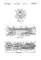
- FIG. 1depicts a pacing lead having a multilumen tubing and at least one ring electrode constructed according to the description of the present invention
- FIG. 2is a partially cross-sectional, exploded view of a portion of FIG. 1, depicting the connection between the multilumen tubing and a ring electrode according to the present invention
- FIG. 3is a generally axial cross-sectional view, depicting the connection between the multilumen tubing and the electrode;
- FIG. 4is a cross-sectional view taken along lines 4--4 of FIG. 3, depicting the cylindrical electrode
- FIG. 5is a first alternative embodiment of the ring electrode of FIG. 1;
- FIG. 6is a second alternative embodiment of a ring electrode assembly.
- FIG. 1shows a pacing lead 20 according to the present invention.
- the pacing lead 20has an elongated lead body 22 which includes electrical conductors extending through lumens within a multilumen tubing 24.
- the multilumen tubing 24is preferably fabricated of silicon rubber, polyurethane or another suitable insulative material having the propertiesof biocompatibility, biostability and flexibility.
- a connector assembly 28whichis provided with sealing rings 30 and which includes a terminal pin 32 and ring terminals 34, 36 and 38.
- the portions of the connector assembly 28 spacing-apart the ring terminals 34, 36 and 38may be fabricated from segments of multilumen tubing of silicon rubber, polyurethane or other suitable insulative plastic, assembled in the manner discussed herein below.
- the terminal pin 32 and ring terminals 34, 36 and 38are preferablyfabricated of a stainless steel or other suitable conductive material.
- a tine sheath 44which includes a plurality of individual tines 46 may be located immediately proximal to a tip electrode 50 at the distal end 40 ofthe electrode assembly 42. Pliant tines 46 engage the endocardial tissue and urge the tip electrode 50 into contact with the endocardium following implantation in a direction parallel to the axis of electrode assembly 42.
- Short segments of multilumen tubing 24may be used to form the lead body 22between the respective ring terminals 34, 36 and 38, as well as between thering electrodes 52, 54 and 56.
- the present inventionaddresses the assemblyand joining of the ring electrodes 52, 54, 56 or ring terminals 34, 36, 38 to the multilumen tubing 24, and the electrical terminal connections with the respective electrical conductors which terminate at the electrodes or conductors.
- FIG. 2depicts a detailed exploded view of the area about electrode 52 depicting the interconnection of the multilumen tubing 24 and the ring electrode 52. It may be understood that the design shown in FIG. 2 and described below can also be incorporated for the ring electrode 54, as well as for the ring terminals 34 and 36. For reasons discussed below, a different design incorporating similar fundamental components may be required for the ring terminal 38 or ring electrode 56 if there are an equal number of conductors and lumens at the point of connection to the ring electrode 56 or ring terminal 38.
- the multilumen tubing 24has a generally cylindrical cross-section and four lumens 60, 62, 64 and 66, which are spaced-apart and axially aligned to extend along the length of the multilumen tubing 24.
- the lumens 60, 64provide enclosed pathways for electrical conductors 70 and 74.
- conductors 72 and 76located within lumens 62and 66 have been coupled to the electrodes 54 or 56 (FIG. 1) of the pacing lead 20, proximally of the ring electrode 52.
- conductor 70passes through the ring electrode 52 and is electricallyconnected to the tip electrode 50 and the terminal pin 32.
- the electrical conductors 70, 72, 74 and 76are preferably helical coils which, when inserted through the respective lumens 60, 62, 64, 66, define an internal chamber or passageway 78.
- One of these passageways 78may allow for the insertion of a stiffening guidewire stylet (not shown) whichallows the physician to insert and guide the pacing lead 20 through the vein(s) into the heart (not shown).
- the passageway 78also provides a conduit susceptible to the invasion of body fluids if the integrity of the connection between the multilumen tubing 24 and the electrode 52 is not maintained.
- the ring electrode 52depicted partially in phantom, is a generally cylindrical solid element having four bores 80, 82, 84 and 86, drilled therethrough.
- the bores 80, 82, 84 and 86are positioned to coaxially align with the lumens 60, 62, 64 and 66, respectively, of the multilumen tubing 24.
- the ring electrode 52is preferably formed from an electricallyconductive, yet biocompatible material, such as stainless steel, MP-35N, Elgiloy, titanium, platinum-iridium, gold, silver, carbon, or other suitable material.
- a means for interconnecting and affixing the ring electrode 52 to the multilumen tubing 24is depicted.
- thisincludes a stabilizing element 90, which is a cylindrical rigid element having a length greater than the axial length of the ring electrode 52.
- the stabilizing elementis inserted through the bore 86 of ring electrode 52 and extends from the opposite faces thereof into the lumen 66 of the abutting multilumen tubing 24.
- the stabilizing element 90enhances the interconnection between the ring electrode 52 and the multilumen tubing 24, and is secured to both of these elements by an appropriate adhesive or by welding.
- the stabilizing element 90may be formed from a metallic material compatible with the ring electrode material, or may be formed from an appropriate rigid composite or plastic material.
- a connector pin 94is depicted as inserted into the bore 84 of the ring electrode 52.
- a head portion 96 of the connector pin 94has an outer diameter which closely matches the inner diameter of the bore 84 to provide a secure interference fit, electrical contact.
- the pin 94can be laser welded to the ring electrode 52.
- the connector pin 94also has a tail portion 98 which extends from the head portion 96 into thepassageway 78 defined by the electrical conductor 74 within lumen 64 of themultilumen tubing 24. The tail 98 is electrically joined to the conductor 74, either by crimping or by welding.
- the means for interconnecting and affixing the ring electrode 52 and multilumen tubing 24may also be defined by or include a cylindrical insulating element 100, passing through bore 80 of the ring electrode 52.
- the cylindrical insulating element 100allows pass-through of the electrical conductor 70 through the ring electrode 52 without electrical contact or shorting of the conductor 70 to the ring electrode 52.
- the cylindrical insulating element 100may have a length equal to the axial length of the ring electrode 52. However, it is preferable that the cylindrical insulating element 100 extends from the ring electrode 52 in either or both directions and is inserted into a receiving cylindrical bore 102 formed in the facing ends of the multilumen tubing 24, coaxially with the lumen 60.
- the ring electrode 52, multilumen tubing 24, stabilizing element 90, connector 94, and cylindrical insulating element 100are assembled, they are bonded together with an appropriate glue or cement. Moreover, by the construction depicted and illustrated herein, the connections between the facing ends of the ring electrode 52 and the multilumen tubing 24 are maintained by the stabilizing element 90 as well as the cylindrical insulating element 100, which extend from the ring electrode 52 into the respective lumens 66, 60 of the multilumen tubing 24.
- FIG. 3depicts an axial cross-sectional view of the assembled ring electrode 52 and multilumen tubing 24 illustrated in the exploded view of FIG. 2.
- the connection of the multilumen tubing 24 and the ring electrode 52isstabilized by the stabilizing element 90 so that bending at the joint of the abutting faces of the multilumen tubing 24 and the ring electrode 52 is minimized due to the rigid nature of the stabilizing element 90 as wellas the cylindrical insulating element 100 and the connecter pin 94.
- the ring electrode 52is depicted as having an axial length which is less than the axial length of the cylindrical insulating element 100 or the axial length of the stabilizing element 90.
- the length of the cylindrical insulating element 100may be equal to the length of the ring electrode 52.
- the lengthsof both the cylindrical insulating element 100 and the stabilizing element 90are greater than the length of the ring electrode 52.
- the length of thestabilizing elementis preferably in the range of between about 1.5 to 2.5 times the length of the ring electrode 52.
- FIG. 3also illustrates that the connector pin 94 has a head portion 96 having a diameter greater than the diameter of the passageway 78 within the conductor 74.
- the head portion 96 and tail portion 98 of the connecter pin 94may be substantially uniform, and the diameter of bore 84 would be formed to match the outer diameter of the head portion 96of the connecter pin 94.
- the diameter of bore 84 through ring electrode 52is substantially equal to the diameter of the lumen 64 and the connector pin 94 is designed to have a head portion 96 having a greater diameter than the tail portion 98.
- the bore 80 through ring electrode 52which accommodates the cylindrical insulating element 100, is preferably greater in diameter than the diameter of the respective lumen 60. This difference is equal to the wall thickness of the cylindrical insulating element 100, which has an internal diameter allowing pass-through of the conductor 70. It may also be appreciated that, for a multilumen tubing 24 which is configured to receive projecting end portions of the cylindrical insulating element 100, the respective lumen 60 must be drilled out to increase its inner diameter near the abutting face of the multilumen tubing 24 to allow the lumen 60 to receive the cylindrical insulating element 100.
- the relative diameters of the various components making up the connection between the multilumen tubing 24 and the ring electrode 52may also be better understood from a review of FIG. 4, which is a cross-sectional viewthrough the middle of the ring electrode 52.
- the ring electrode 52is depicted as being a solid cross-sectional cylinder having the four axialbores 80, 82, 84, 86 therein.
- the axial bores 80, 82 and 86 in ring electrode 52are configured to have diameters essentially equal to the diameter of the respective lumens 60, 62 and 66 (FIG. 2) which they abut.
- FIG. 5depicts an alternative embodiment of a ring electrode 152 wherein the ring electrode 152 is initially configured to have a projecting cylinder or stabilizing element 190 which performs the same function as the stabilizing pin 90 discussed above.
- the projecting solid cylinders 190, 192insert into vacant lumens within the multilumen tubing 24.
- the lumen 64accommodates a conductor 74 terminating via a connection pin 194 to the ring electrode 152.
- the connection pin 194has atail portion 196 extending into the conductor 74 which is crimped or weldedor cemented thereto within the lumen 64, and a head portion 198 which extends into a recess 184 within the ring electrode 152, and is electrically secured thereto.
- the ring electrode 152may havethe projecting cylinder 192 extending into the now vacant lumen 62 of the multilumen tubing 24 at the other side of the ring electrode 152 from the connection pin 194.
- the incorporation of the stabilizing element 90 or the projecting cylinders 190, 192operates to seal off the empty lumen from invasion by body fluids.
- the elementscan all be interconnected and bonded, by first coating them with an appropriate cement.
- the projecting portions of the stabilizing element 90 and cylinders 190, 192will be solidly bonded to the internal surfaces of the vacant lumens. In this configuration, it is difficult for body fluids to invade the lumens even if the fluids invade the intersection between the facing portions of the multilumen tubing 24 and the ring electrode 52 (or 152).
- the ring electrode 56 in FIG. 1it may be appreciated that there may be no vacant lumens to receive the stabilizing element 90. Accordingly, a different design for the ring electrode 56 may be required, as depicted inFIG. 6. The same design can also be incorporated for the ring terminal 38 of FIG. 1.
- the electrode 56includes a plurality of insulating cylinders 110, 114 and 116, which are preferably inserted into and through bores 120, 124, 126 defined within the ring electrode 56.
- the insulating cylinders 110, 114 and 116require that the multilumen tubing 24 abutting the electrode 56 has the lumens 60, 64, 66 bored out to receive the insulating cylinders 110, 114, 116, respectively.
- These insulating cylindersallow pass-through of the respective electrical conductors 70, 74 and 76.
- a projecting cylinder 140can be designed to project from the ring electrode 56 (or it may be inserted intoand project from a portion of the bore 122) to extend into the vacant lumen62, opposite pin connector 150 in the ring electrode 56.
- the present inventiondefines a method of constructing an in-line ring electrode in a pacing lead.
- the methodincludes cutting a preformed multilumen tubing having a plurality of lumens into at least two segments, and forming cylindrical electrodes having at least two axially extending bores corresponding to at least two of said lumens. These components are assembled by inserting at least two conductors through two of the lumens of at least one of said multilumen tubing segments, electrically interconnecting the cylindrical electrode toat least one of the two conductors, and interconnecting and affixing the cylindrical electrode between the multilumen tubing segments.
- the step of interconnecting and affixingmay include providing at least oneconnecting element projecting from the cylindrical electrode and inserted into at least one of the lumens of each of said respective multilumen tubing segments.
- the connecting elementis preferably the stabilizer pin inserted through one of the bores of the cylindrical electrode.
- the method of forming the pacing leadmay further include inserting an insulating cylinder through one of the bores of the cylindrical electrode.
- the insulating cylinderprojects from the cylindrical electrode into one ofthe lumens of the multilumen tubing.
- the insulating cylinderis configured to have an internal bore extending therethrough to accommodate pass-through of one of the electrical conductors insulated from the cylindrical electrode.
Landscapes
- Health & Medical Sciences (AREA)
- Heart & Thoracic Surgery (AREA)
- Vascular Medicine (AREA)
- Cardiology (AREA)
- Engineering & Computer Science (AREA)
- Biomedical Technology (AREA)
- Nuclear Medicine, Radiotherapy & Molecular Imaging (AREA)
- Radiology & Medical Imaging (AREA)
- Life Sciences & Earth Sciences (AREA)
- Animal Behavior & Ethology (AREA)
- General Health & Medical Sciences (AREA)
- Public Health (AREA)
- Veterinary Medicine (AREA)
- Electrotherapy Devices (AREA)
Abstract
Description
Claims (19)
Priority Applications (1)
| Application Number | Priority Date | Filing Date | Title |
|---|---|---|---|
| US07/997,804US5330522A (en) | 1992-12-29 | 1992-12-29 | Ring electrode for a multilumen lead and method of constructing a multilumen lead |
Applications Claiming Priority (1)
| Application Number | Priority Date | Filing Date | Title |
|---|---|---|---|
| US07/997,804US5330522A (en) | 1992-12-29 | 1992-12-29 | Ring electrode for a multilumen lead and method of constructing a multilumen lead |
Publications (1)
| Publication Number | Publication Date |
|---|---|
| US5330522Atrue US5330522A (en) | 1994-07-19 |
Family
ID=25544421
Family Applications (1)
| Application Number | Title | Priority Date | Filing Date |
|---|---|---|---|
| US07/997,804Expired - LifetimeUS5330522A (en) | 1992-12-29 | 1992-12-29 | Ring electrode for a multilumen lead and method of constructing a multilumen lead |
Country Status (1)
| Country | Link |
|---|---|
| US (1) | US5330522A (en) |
Cited By (68)
| Publication number | Priority date | Publication date | Assignee | Title |
|---|---|---|---|---|
| US5549109A (en)* | 1993-10-01 | 1996-08-27 | Target Therapeutics, Inc. | Sheathed multipolar catheter and multipolar guidewire for sensing cardiac electrical activity |
| US5571163A (en)* | 1993-09-22 | 1996-11-05 | Pacesetter, Inc. | Combination pacing and defibrillating lead having atrial sensing capability and method |
| US5645082A (en)* | 1993-01-29 | 1997-07-08 | Cardima, Inc. | Intravascular method and system for treating arrhythmia |
| US5645064A (en)* | 1992-01-29 | 1997-07-08 | Cardima, Inc. | High resolution intravascular signal detection |
| US5706809A (en)* | 1993-01-29 | 1998-01-13 | Cardima, Inc. | Method and system for using multiple intravascular sensing devices to detect electrical activity |
| US6018684A (en)* | 1998-07-30 | 2000-01-25 | Cardiac Pacemakers, Inc. | Slotted pacing/shocking electrode |
| US6088610A (en)* | 1993-01-29 | 2000-07-11 | Cardima, Inc. | Method and system for using multiple intravascular sensing devices to detect electrical activity |
| US6181971B1 (en)* | 1998-12-09 | 2001-01-30 | Pacesetter, Inc. | Joining conductor cables and electrodes on a multi-lumen lead body |
| US6249709B1 (en) | 1999-02-18 | 2001-06-19 | Intermedics Inc. | Endocardial defibrillation lead with multi-lumen body and axially mounted distal electrode |
| US6253111B1 (en) | 1998-03-30 | 2001-06-26 | Pacesetter, Inc. | Multi-conductor lead |
| US6263250B1 (en) | 1999-07-13 | 2001-07-17 | Cardiac Pacemakers, Inc. | Ring electrode with porous member |
| US6456888B1 (en) | 2000-08-18 | 2002-09-24 | Cardiac Pacemakers, Inc. | Geometry for coupling and electrode to a conductor |
| US20040068303A1 (en)* | 2002-10-04 | 2004-04-08 | Ostroff Alan H. | Implantable cardiac system with a selectable active housing |
| US20040082986A1 (en)* | 2002-10-23 | 2004-04-29 | Randy Westlund | Unitary medical electrical lead and methods for making and using same |
| US20040097965A1 (en)* | 2002-11-19 | 2004-05-20 | Gardeski Kenneth C. | Multilumen body for an implantable medical device |
| US20040167595A1 (en)* | 2003-02-21 | 2004-08-26 | Medtronic, Inc. | Novel shaft constructions for a medical device |
| US20050004642A1 (en)* | 1998-11-09 | 2005-01-06 | Medtronic, Inc. | Implantable medical lead including overlay |
| US20050131509A1 (en)* | 2003-12-16 | 2005-06-16 | Liliana Atanassoska | Coatings for implantable electrodes |
| US20050138792A1 (en)* | 1999-04-26 | 2005-06-30 | Black Damon R. | Method of forming a lead |
| US20050228469A1 (en)* | 2004-04-12 | 2005-10-13 | Cardiac Pacemakers, Inc. | Electrode and conductor interconnect and method therefor |
| US20060173262A1 (en)* | 2005-01-31 | 2006-08-03 | Medtronic, Inc. | Medical lead with segmented electrode |
| WO2006058132A3 (en)* | 2004-11-24 | 2007-01-18 | Flea Street Translational Llc | Sensor-assisted catheter-based procedures |
| US20070142890A1 (en)* | 2005-12-19 | 2007-06-21 | Cardiac Pacemakers, Inc. | Interconnections of implantable lead conductors and electrodes and reinforcement therefor |
| US20070179582A1 (en)* | 2006-01-31 | 2007-08-02 | Marshall Mark T | Polymer reinforced coil conductor for torque transmission |
| US20070179577A1 (en)* | 2006-01-31 | 2007-08-02 | Marshall Mark T | Medical electrical lead having improved inductance |
| US20070250143A1 (en)* | 2006-04-19 | 2007-10-25 | Sommer John L | Multi-conductor ribbon coiled medical device lead |
| US20080095646A1 (en)* | 2004-05-20 | 2008-04-24 | Matsushita Electric Industrial Co., Ltd. | Electrically Driven Compressor Integral with Inverter Device, and Vehicle Air Conditioner Where the Compressor is Used |
| US20090198314A1 (en)* | 2008-02-06 | 2009-08-06 | Foster Arthur J | Lead with mri compatible design features |
| US20090281608A1 (en)* | 2008-05-09 | 2009-11-12 | Cardiac Pacemakers, Inc. | Medical lead coil conductor with spacer element |
| US20100001387A1 (en)* | 2007-03-23 | 2010-01-07 | Fujitsu Limited | Electronic device, electronic apparatus mounted with electronic device, article equipped with electronic device and method of producing electronic device |
| US20100010602A1 (en)* | 2006-11-30 | 2010-01-14 | Wedan Steven R | Rf rejecting lead |
| US20100234929A1 (en)* | 2009-03-12 | 2010-09-16 | Torsten Scheuermann | Thin profile conductor assembly for medical device leads |
| US20100256693A1 (en)* | 2009-04-07 | 2010-10-07 | Boston Scientific Neuromodulation Corporation | Insulator layers for leads of implantable electric stimulation systems and methods of making and using |
| US20100331936A1 (en)* | 2009-06-26 | 2010-12-30 | Christopher Perrey | Medical device lead including a unifilar coil with improved torque transmission capacity and reduced mri heating |
| US20100331934A1 (en)* | 2009-06-29 | 2010-12-30 | Boston Scientific Neuromodulation Corporation | Multi-element contact assemblies for electrical stimulation systems and systems and methods of making and using |
| US20110034978A1 (en)* | 2009-08-05 | 2011-02-10 | Boston Scientific Neuromodulation Corporation | Systems and methods for coupling coiled conductors to conductive contacts of an electrical stimulation system |
| US7912557B1 (en)* | 2007-02-13 | 2011-03-22 | Pacesetter, Inc. | Mechanism for, and method of, attaching a lead conductor cable to a lead electrode |
| US20110087299A1 (en)* | 2009-10-08 | 2011-04-14 | Masoud Ameri | Medical device lead including a flared conductive coil |
| US20110093054A1 (en)* | 2009-10-19 | 2011-04-21 | Masoud Ameri | Mri compatible tachycardia lead |
| US20110160828A1 (en)* | 2009-12-31 | 2011-06-30 | Foster Arthur J | Mri conditionally safe lead with low-profile multi-layer conductor for longitudinal expansion |
| US20110160829A1 (en)* | 2009-12-31 | 2011-06-30 | Foster Arthur J | Mri conditionally safe lead with multi-layer conductor |
| US20110160818A1 (en)* | 2009-12-30 | 2011-06-30 | Roger Struve | Mri-conditionally safe medical device lead |
| EP2422839A1 (en)* | 2010-08-31 | 2012-02-29 | BIOTRONIK SE & Co. KG | Electrode catheter, in particular for cardiac therapy |
| US20120151765A1 (en)* | 2010-12-21 | 2012-06-21 | Pacesetter, Inc. | Lead connector end with integrated shunt |
| US20130274844A1 (en)* | 2012-04-17 | 2013-10-17 | Boston Scientific Neuromodulation Corporation | Lead with contact end conductor guide and methods of making and using |
| US20130274843A1 (en)* | 2012-04-17 | 2013-10-17 | Boston Scientific Neuromodulation Corporation | Lead construction for deep brain stimulation |
| US8666512B2 (en) | 2011-11-04 | 2014-03-04 | Cardiac Pacemakers, Inc. | Implantable medical device lead including inner coil reverse-wound relative to shocking coil |
| US8731685B2 (en) | 2007-12-06 | 2014-05-20 | Cardiac Pacemakers, Inc. | Implantable lead having a variable coil conductor pitch |
| US8825181B2 (en) | 2010-08-30 | 2014-09-02 | Cardiac Pacemakers, Inc. | Lead conductor with pitch and torque control for MRI conditionally safe use |
| US8825179B2 (en) | 2012-04-20 | 2014-09-02 | Cardiac Pacemakers, Inc. | Implantable medical device lead including a unifilar coiled cable |
| US8954168B2 (en) | 2012-06-01 | 2015-02-10 | Cardiac Pacemakers, Inc. | Implantable device lead including a distal electrode assembly with a coiled component |
| US8958889B2 (en) | 2012-08-31 | 2015-02-17 | Cardiac Pacemakers, Inc. | MRI compatible lead coil |
| US8983623B2 (en) | 2012-10-18 | 2015-03-17 | Cardiac Pacemakers, Inc. | Inductive element for providing MRI compatibility in an implantable medical device lead |
| US9242088B2 (en) | 2013-11-22 | 2016-01-26 | Simon Fraser University | Apparatus and methods for assisted breathing by transvascular nerve stimulation |
| US9504821B2 (en) | 2014-02-26 | 2016-11-29 | Cardiac Pacemakers, Inc. | Construction of an MRI-safe tachycardia lead |
| US9566436B2 (en) | 2007-01-29 | 2017-02-14 | Simon Fraser University | Transvascular nerve stimulation apparatus and methods |
| US9597509B2 (en) | 2014-01-21 | 2017-03-21 | Simon Fraser University | Systems and related methods for optimization of multi-electrode nerve pacing |
| US9775992B2 (en) | 2015-02-13 | 2017-10-03 | Cardiac Pacemakers, Inc. | Implantable electrode |
| US9776005B2 (en) | 2012-06-21 | 2017-10-03 | Lungpacer Medical Inc. | Transvascular diaphragm pacing systems and methods of use |
| US10039920B1 (en) | 2017-08-02 | 2018-08-07 | Lungpacer Medical, Inc. | Systems and methods for intravascular catheter positioning and/or nerve stimulation |
| US10293164B2 (en) | 2017-05-26 | 2019-05-21 | Lungpacer Medical Inc. | Apparatus and methods for assisted breathing by transvascular nerve stimulation |
| US10512772B2 (en) | 2012-03-05 | 2019-12-24 | Lungpacer Medical Inc. | Transvascular nerve stimulation apparatus and methods |
| US10940308B2 (en) | 2017-08-04 | 2021-03-09 | Lungpacer Medical Inc. | Systems and methods for trans-esophageal sympathetic ganglion recruitment |
| US10987511B2 (en) | 2018-11-08 | 2021-04-27 | Lungpacer Medical Inc. | Stimulation systems and related user interfaces |
| US11357979B2 (en) | 2019-05-16 | 2022-06-14 | Lungpacer Medical Inc. | Systems and methods for sensing and stimulation |
| US11771900B2 (en) | 2019-06-12 | 2023-10-03 | Lungpacer Medical Inc. | Circuitry for medical stimulation systems |
| US11883658B2 (en) | 2017-06-30 | 2024-01-30 | Lungpacer Medical Inc. | Devices and methods for prevention, moderation, and/or treatment of cognitive injury |
| US12029903B2 (en) | 2017-12-11 | 2024-07-09 | Lungpacer Medical Inc. | Systems and methods for strengthening a respiratory muscle |
Citations (5)
| Publication number | Priority date | Publication date | Assignee | Title |
|---|---|---|---|---|
| US4161952A (en)* | 1977-11-01 | 1979-07-24 | Mieczyslaw Mirowski | Wound wire catheter cardioverting electrode |
| US4328812A (en)* | 1980-03-21 | 1982-05-11 | Medtronic, Inc. | Ring electrode for pacing lead |
| US4413636A (en)* | 1979-11-19 | 1983-11-08 | Phillip R. Beutel | Catheter |
| US4944088A (en)* | 1988-05-25 | 1990-07-31 | Medtronic, Inc. | Ring electrode for multiconductor pacing leads |
| US4947866A (en)* | 1988-02-16 | 1990-08-14 | Medtronic, Inc. | Medical electrical lead |
- 1992
- 1992-12-29USUS07/997,804patent/US5330522A/ennot_activeExpired - Lifetime
Patent Citations (5)
| Publication number | Priority date | Publication date | Assignee | Title |
|---|---|---|---|---|
| US4161952A (en)* | 1977-11-01 | 1979-07-24 | Mieczyslaw Mirowski | Wound wire catheter cardioverting electrode |
| US4413636A (en)* | 1979-11-19 | 1983-11-08 | Phillip R. Beutel | Catheter |
| US4328812A (en)* | 1980-03-21 | 1982-05-11 | Medtronic, Inc. | Ring electrode for pacing lead |
| US4947866A (en)* | 1988-02-16 | 1990-08-14 | Medtronic, Inc. | Medical electrical lead |
| US4944088A (en)* | 1988-05-25 | 1990-07-31 | Medtronic, Inc. | Ring electrode for multiconductor pacing leads |
Cited By (157)
| Publication number | Priority date | Publication date | Assignee | Title |
|---|---|---|---|---|
| US5645064A (en)* | 1992-01-29 | 1997-07-08 | Cardima, Inc. | High resolution intravascular signal detection |
| US6088610A (en)* | 1993-01-29 | 2000-07-11 | Cardima, Inc. | Method and system for using multiple intravascular sensing devices to detect electrical activity |
| US5645082A (en)* | 1993-01-29 | 1997-07-08 | Cardima, Inc. | Intravascular method and system for treating arrhythmia |
| US5685322A (en)* | 1993-01-29 | 1997-11-11 | Cardima, Inc. | Intravascular system for treating arrhythmia |
| US5699796A (en)* | 1993-01-29 | 1997-12-23 | Cardima, Inc. | High resolution intravascular signal detection |
| US5706809A (en)* | 1993-01-29 | 1998-01-13 | Cardima, Inc. | Method and system for using multiple intravascular sensing devices to detect electrical activity |
| US5881732A (en)* | 1993-01-29 | 1999-03-16 | Cardima, Inc. | Intravascular method and system for treating arrhythmia |
| US5960796A (en)* | 1993-01-29 | 1999-10-05 | Cardima, Inc. | Intravascular method and device for occluding a body lumen |
| US5571163A (en)* | 1993-09-22 | 1996-11-05 | Pacesetter, Inc. | Combination pacing and defibrillating lead having atrial sensing capability and method |
| US5549109A (en)* | 1993-10-01 | 1996-08-27 | Target Therapeutics, Inc. | Sheathed multipolar catheter and multipolar guidewire for sensing cardiac electrical activity |
| US5711298A (en)* | 1994-01-27 | 1998-01-27 | Cardima, Inc. | High resolution intravascular signal detection |
| US5957842A (en)* | 1994-01-27 | 1999-09-28 | Cardima, Inc. | High resolution intravascular signal detection |
| US6253111B1 (en) | 1998-03-30 | 2001-06-26 | Pacesetter, Inc. | Multi-conductor lead |
| WO2000006247A1 (en)* | 1998-07-30 | 2000-02-10 | Cardiac Pacemakers, Inc. | Slotted pacing/shocking electrode |
| US6018684A (en)* | 1998-07-30 | 2000-01-25 | Cardiac Pacemakers, Inc. | Slotted pacing/shocking electrode |
| US20050004642A1 (en)* | 1998-11-09 | 2005-01-06 | Medtronic, Inc. | Implantable medical lead including overlay |
| US6505401B1 (en)* | 1998-12-09 | 2003-01-14 | Pacesetter, Inc. | Method of making an implantable medical electrical lead |
| US6181971B1 (en)* | 1998-12-09 | 2001-01-30 | Pacesetter, Inc. | Joining conductor cables and electrodes on a multi-lumen lead body |
| US6249709B1 (en) | 1999-02-18 | 2001-06-19 | Intermedics Inc. | Endocardial defibrillation lead with multi-lumen body and axially mounted distal electrode |
| US6381835B1 (en) | 1999-02-18 | 2002-05-07 | Intermedics Inc. | Endocardial defibrillation lead with multi-lumen body and axially mounted distal electrode |
| US20050138792A1 (en)* | 1999-04-26 | 2005-06-30 | Black Damon R. | Method of forming a lead |
| US8316537B2 (en) | 1999-04-26 | 2012-11-27 | Advanced Neuromodulation Systems, Inc. | Method of forming a lead |
| US20100077606A1 (en)* | 1999-04-26 | 2010-04-01 | Damon Ray Black | Method of forming a lead |
| US8671566B2 (en) | 1999-04-26 | 2014-03-18 | Advanced Neuromodulation Systems, Inc. | Method of forming a lead |
| US6263250B1 (en) | 1999-07-13 | 2001-07-17 | Cardiac Pacemakers, Inc. | Ring electrode with porous member |
| US6516232B2 (en) | 1999-07-13 | 2003-02-04 | Cardiac Pacemakers, Inc. | Ring electrode with porous member |
| US6456888B1 (en) | 2000-08-18 | 2002-09-24 | Cardiac Pacemakers, Inc. | Geometry for coupling and electrode to a conductor |
| US7062329B2 (en)* | 2002-10-04 | 2006-06-13 | Cameron Health, Inc. | Implantable cardiac system with a selectable active housing |
| US20040068303A1 (en)* | 2002-10-04 | 2004-04-08 | Ostroff Alan H. | Implantable cardiac system with a selectable active housing |
| US20040082986A1 (en)* | 2002-10-23 | 2004-04-29 | Randy Westlund | Unitary medical electrical lead and methods for making and using same |
| US7130700B2 (en)* | 2002-11-19 | 2006-10-31 | Medtronic, Inc. | Multilumen body for an implantable medical device |
| US20040097965A1 (en)* | 2002-11-19 | 2004-05-20 | Gardeski Kenneth C. | Multilumen body for an implantable medical device |
| US20040167595A1 (en)* | 2003-02-21 | 2004-08-26 | Medtronic, Inc. | Novel shaft constructions for a medical device |
| US7120502B2 (en) | 2003-02-21 | 2006-10-10 | Medtronic, Inc. | Shaft constructions for a medical device |
| US8017179B2 (en) | 2003-12-16 | 2011-09-13 | Cardiac Pacemakers, Inc. | Coatings for implantable electrodes |
| US8017178B2 (en) | 2003-12-16 | 2011-09-13 | Cardiac Pacemakers, Inc. | Coatings for implantable electrodes |
| US20060035026A1 (en)* | 2003-12-16 | 2006-02-16 | Cardiac Pacemakers, Inc. | Coatings for implantable electrodes |
| US20050131509A1 (en)* | 2003-12-16 | 2005-06-16 | Liliana Atanassoska | Coatings for implantable electrodes |
| US20050228469A1 (en)* | 2004-04-12 | 2005-10-13 | Cardiac Pacemakers, Inc. | Electrode and conductor interconnect and method therefor |
| US20080095646A1 (en)* | 2004-05-20 | 2008-04-24 | Matsushita Electric Industrial Co., Ltd. | Electrically Driven Compressor Integral with Inverter Device, and Vehicle Air Conditioner Where the Compressor is Used |
| US20090299445A1 (en)* | 2004-11-24 | 2009-12-03 | Flea Street Translational, Llc | Sensor-assisted catheter-based procedures |
| WO2006058132A3 (en)* | 2004-11-24 | 2007-01-18 | Flea Street Translational Llc | Sensor-assisted catheter-based procedures |
| US9463313B2 (en) | 2004-11-24 | 2016-10-11 | Flea Street Translational, Llc | Sensor-assisted catheter-based procedures |
| US20060173262A1 (en)* | 2005-01-31 | 2006-08-03 | Medtronic, Inc. | Medical lead with segmented electrode |
| US8000808B2 (en)* | 2005-01-31 | 2011-08-16 | Medtronic, Inc. | Medical lead with segmented electrode |
| US20090222074A1 (en)* | 2005-12-19 | 2009-09-03 | Zarembo Paul E | Interconnections of implantable lead conductors and electrodes and reinforcement therefor |
| US7546165B2 (en)* | 2005-12-19 | 2009-06-09 | Cardiac Pacemakers, Inc. | Interconnections of implantable lead conductors and electrodes and reinforcement therefor |
| US8055354B2 (en) | 2005-12-19 | 2011-11-08 | Cardiac Pacemakers, Inc. | Interconnections of implantable lead conductors and electrodes and reinforcement therefor |
| US20070142890A1 (en)* | 2005-12-19 | 2007-06-21 | Cardiac Pacemakers, Inc. | Interconnections of implantable lead conductors and electrodes and reinforcement therefor |
| US9901731B2 (en) | 2006-01-31 | 2018-02-27 | Medtronic, Inc. | Medical electrical lead having improved inductance |
| US20070179577A1 (en)* | 2006-01-31 | 2007-08-02 | Marshall Mark T | Medical electrical lead having improved inductance |
| US20070179582A1 (en)* | 2006-01-31 | 2007-08-02 | Marshall Mark T | Polymer reinforced coil conductor for torque transmission |
| US20070250143A1 (en)* | 2006-04-19 | 2007-10-25 | Sommer John L | Multi-conductor ribbon coiled medical device lead |
| US20100010602A1 (en)* | 2006-11-30 | 2010-01-14 | Wedan Steven R | Rf rejecting lead |
| US7986999B2 (en) | 2006-11-30 | 2011-07-26 | Cardiac Pacemakers, Inc. | RF rejecting lead |
| US8670840B2 (en) | 2006-11-30 | 2014-03-11 | Cardiac Pacemakers, Inc. | RF rejecting lead |
| US8401671B2 (en) | 2006-11-30 | 2013-03-19 | Cardiac Pacemakers, Inc. | RF rejecting lead |
| US8170688B2 (en) | 2006-11-30 | 2012-05-01 | Cardiac Pacemakers, Inc. | RF rejecting lead |
| US20110238146A1 (en)* | 2006-11-30 | 2011-09-29 | Wedan Steven R | Rf rejecting lead |
| US11027130B2 (en) | 2007-01-29 | 2021-06-08 | Lungpacer Medical Inc. | Transvascular nerve stimulation apparatus and methods |
| US9950167B2 (en) | 2007-01-29 | 2018-04-24 | Lungpacer Medical, Inc. | Transvascular nerve stimulation apparatus and methods |
| US10561843B2 (en) | 2007-01-29 | 2020-02-18 | Lungpacer Medical, Inc. | Transvascular nerve stimulation apparatus and methods |
| US10864374B2 (en) | 2007-01-29 | 2020-12-15 | Lungpacer Medical Inc. | Transvascular nerve stimulation apparatus and methods |
| US12268877B2 (en) | 2007-01-29 | 2025-04-08 | Lungpacer Medical Inc. | Transvascular nerve stimulation apparatus and methods |
| US10792499B2 (en) | 2007-01-29 | 2020-10-06 | Lungpacer Medical Inc. | Transvascular nerve stimulation apparatus and methods |
| US10765867B2 (en) | 2007-01-29 | 2020-09-08 | Lungpacer Medical Inc. | Transvascular nerve stimulation apparatus and methods |
| US9566436B2 (en) | 2007-01-29 | 2017-02-14 | Simon Fraser University | Transvascular nerve stimulation apparatus and methods |
| US10022546B2 (en) | 2007-01-29 | 2018-07-17 | Lungpacer Medical Inc. | Transvascular nerve stimulation apparatus and methods |
| US9968785B2 (en) | 2007-01-29 | 2018-05-15 | Lungpacer Medical, Inc. | Transvascular nerve stimulation apparatus and methods |
| US8311646B2 (en) | 2007-02-13 | 2012-11-13 | Pacesetter, Inc. | Mechanism for, and method of, attaching a lead conductor cable to a lead electrode |
| US7912557B1 (en)* | 2007-02-13 | 2011-03-22 | Pacesetter, Inc. | Mechanism for, and method of, attaching a lead conductor cable to a lead electrode |
| US20110137392A1 (en)* | 2007-02-13 | 2011-06-09 | Pacesetter, Inc. | Mechanism for, and method of, attaching a lead conductor cable to a lead electrode |
| US20100001387A1 (en)* | 2007-03-23 | 2010-01-07 | Fujitsu Limited | Electronic device, electronic apparatus mounted with electronic device, article equipped with electronic device and method of producing electronic device |
| US8731685B2 (en) | 2007-12-06 | 2014-05-20 | Cardiac Pacemakers, Inc. | Implantable lead having a variable coil conductor pitch |
| US8666508B2 (en) | 2008-02-06 | 2014-03-04 | Cardiac Pacemakers, Inc. | Lead with MRI compatible design features |
| US8244346B2 (en) | 2008-02-06 | 2012-08-14 | Cardiac Pacemakers, Inc. | Lead with MRI compatible design features |
| US20090198314A1 (en)* | 2008-02-06 | 2009-08-06 | Foster Arthur J | Lead with mri compatible design features |
| US8103360B2 (en) | 2008-05-09 | 2012-01-24 | Foster Arthur J | Medical lead coil conductor with spacer element |
| US8688236B2 (en) | 2008-05-09 | 2014-04-01 | Cardiac Pacemakers, Inc. | Medical lead coil conductor with spacer element |
| US20090281608A1 (en)* | 2008-05-09 | 2009-11-12 | Cardiac Pacemakers, Inc. | Medical lead coil conductor with spacer element |
| US20100234929A1 (en)* | 2009-03-12 | 2010-09-16 | Torsten Scheuermann | Thin profile conductor assembly for medical device leads |
| US9084883B2 (en) | 2009-03-12 | 2015-07-21 | Cardiac Pacemakers, Inc. | Thin profile conductor assembly for medical device leads |
| US8478423B2 (en)* | 2009-04-07 | 2013-07-02 | Boston Scientific Neuromodulation Corporation | Insulator layers for leads of implantable electric stimulation systems and methods of making and using |
| US20100256693A1 (en)* | 2009-04-07 | 2010-10-07 | Boston Scientific Neuromodulation Corporation | Insulator layers for leads of implantable electric stimulation systems and methods of making and using |
| US20100331936A1 (en)* | 2009-06-26 | 2010-12-30 | Christopher Perrey | Medical device lead including a unifilar coil with improved torque transmission capacity and reduced mri heating |
| US8744600B2 (en) | 2009-06-26 | 2014-06-03 | Cardiac Pacemakers, Inc. | Medical device lead including a unifilar coil with improved torque transmission capacity and reduced MRI heating |
| US8332050B2 (en) | 2009-06-26 | 2012-12-11 | Cardiac Pacemakers, Inc. | Medical device lead including a unifilar coil with improved torque transmission capacity and reduced MRI heating |
| US8406896B2 (en)* | 2009-06-29 | 2013-03-26 | Boston Scientific Neuromodulation Corporation | Multi-element contact assemblies for electrical stimulation systems and systems and methods of making and using |
| US20100331934A1 (en)* | 2009-06-29 | 2010-12-30 | Boston Scientific Neuromodulation Corporation | Multi-element contact assemblies for electrical stimulation systems and systems and methods of making and using |
| US9190793B2 (en) | 2009-08-05 | 2015-11-17 | Boston Scientific Neuromodulation Corporation | Systems and methods for coupling coiled conductors to conductive contacts of an electrical stimulation system |
| US20110034978A1 (en)* | 2009-08-05 | 2011-02-10 | Boston Scientific Neuromodulation Corporation | Systems and methods for coupling coiled conductors to conductive contacts of an electrical stimulation system |
| US8380325B2 (en)* | 2009-08-05 | 2013-02-19 | Boston Scientific Neuromodulation Corporation | Systems and methods for coupling coiled conductors to conductive contacts of an electrical stimulation system |
| US20110087299A1 (en)* | 2009-10-08 | 2011-04-14 | Masoud Ameri | Medical device lead including a flared conductive coil |
| US8335572B2 (en) | 2009-10-08 | 2012-12-18 | Cardiac Pacemakers, Inc. | Medical device lead including a flared conductive coil |
| US20110093054A1 (en)* | 2009-10-19 | 2011-04-21 | Masoud Ameri | Mri compatible tachycardia lead |
| US9254380B2 (en) | 2009-10-19 | 2016-02-09 | Cardiac Pacemakers, Inc. | MRI compatible tachycardia lead |
| US9750944B2 (en) | 2009-12-30 | 2017-09-05 | Cardiac Pacemakers, Inc. | MRI-conditionally safe medical device lead |
| US20110160818A1 (en)* | 2009-12-30 | 2011-06-30 | Roger Struve | Mri-conditionally safe medical device lead |
| US8676351B2 (en) | 2009-12-31 | 2014-03-18 | Cardiac Pacemakers, Inc. | MRI conditionally safe lead with low-profile multi-layer conductor for longitudinal expansion |
| US8798767B2 (en) | 2009-12-31 | 2014-08-05 | Cardiac Pacemakers, Inc. | MRI conditionally safe lead with multi-layer conductor |
| US9050457B2 (en) | 2009-12-31 | 2015-06-09 | Cardiac Pacemakers, Inc. | MRI conditionally safe lead with low-profile conductor for longitudinal expansion |
| US9199077B2 (en) | 2009-12-31 | 2015-12-01 | Cardiac Pacemakers, Inc. | MRI conditionally safe lead with multi-layer conductor |
| US20110160829A1 (en)* | 2009-12-31 | 2011-06-30 | Foster Arthur J | Mri conditionally safe lead with multi-layer conductor |
| US8391994B2 (en) | 2009-12-31 | 2013-03-05 | Cardiac Pacemakers, Inc. | MRI conditionally safe lead with low-profile multi-layer conductor for longitudinal expansion |
| US20110160828A1 (en)* | 2009-12-31 | 2011-06-30 | Foster Arthur J | Mri conditionally safe lead with low-profile multi-layer conductor for longitudinal expansion |
| US8825181B2 (en) | 2010-08-30 | 2014-09-02 | Cardiac Pacemakers, Inc. | Lead conductor with pitch and torque control for MRI conditionally safe use |
| EP2422839A1 (en)* | 2010-08-31 | 2012-02-29 | BIOTRONIK SE & Co. KG | Electrode catheter, in particular for cardiac therapy |
| US8504173B2 (en) | 2010-08-31 | 2013-08-06 | Biotronik Se & Co. Kg | Electrode catheter, in particular for cardiac therapy |
| US20120151765A1 (en)* | 2010-12-21 | 2012-06-21 | Pacesetter, Inc. | Lead connector end with integrated shunt |
| US8666512B2 (en) | 2011-11-04 | 2014-03-04 | Cardiac Pacemakers, Inc. | Implantable medical device lead including inner coil reverse-wound relative to shocking coil |
| US11369787B2 (en) | 2012-03-05 | 2022-06-28 | Lungpacer Medical Inc. | Transvascular nerve stimulation apparatus and methods |
| US10512772B2 (en) | 2012-03-05 | 2019-12-24 | Lungpacer Medical Inc. | Transvascular nerve stimulation apparatus and methods |
| US9827413B2 (en)* | 2012-04-17 | 2017-11-28 | Boston Scientific Neuromodulation Corporation | Lead construction for deep brain stimulation |
| US9878148B2 (en)* | 2012-04-17 | 2018-01-30 | Boston Scientific Neuromodulation Corporation | Lead with contact end conductor guide and methods of making and using |
| US20130274843A1 (en)* | 2012-04-17 | 2013-10-17 | Boston Scientific Neuromodulation Corporation | Lead construction for deep brain stimulation |
| US20130274844A1 (en)* | 2012-04-17 | 2013-10-17 | Boston Scientific Neuromodulation Corporation | Lead with contact end conductor guide and methods of making and using |
| US8825179B2 (en) | 2012-04-20 | 2014-09-02 | Cardiac Pacemakers, Inc. | Implantable medical device lead including a unifilar coiled cable |
| US9333344B2 (en) | 2012-06-01 | 2016-05-10 | Cardiac Pacemakers, Inc. | Implantable device lead including a distal electrode assembly with a coiled component |
| US8954168B2 (en) | 2012-06-01 | 2015-02-10 | Cardiac Pacemakers, Inc. | Implantable device lead including a distal electrode assembly with a coiled component |
| US11357985B2 (en) | 2012-06-21 | 2022-06-14 | Lungpacer Medical Inc. | Transvascular diaphragm pacing systems and methods of use |
| US10589097B2 (en) | 2012-06-21 | 2020-03-17 | Lungpacer Medical Inc. | Transvascular diaphragm pacing systems and methods of use |
| US10406367B2 (en) | 2012-06-21 | 2019-09-10 | Lungpacer Medical Inc. | Transvascular diaphragm pacing system and methods of use |
| US10561844B2 (en) | 2012-06-21 | 2020-02-18 | Lungpacer Medical Inc. | Diaphragm pacing systems and methods of use |
| US9776005B2 (en) | 2012-06-21 | 2017-10-03 | Lungpacer Medical Inc. | Transvascular diaphragm pacing systems and methods of use |
| US8958889B2 (en) | 2012-08-31 | 2015-02-17 | Cardiac Pacemakers, Inc. | MRI compatible lead coil |
| US9504822B2 (en) | 2012-10-18 | 2016-11-29 | Cardiac Pacemakers, Inc. | Inductive element for providing MRI compatibility in an implantable medical device lead |
| US8983623B2 (en) | 2012-10-18 | 2015-03-17 | Cardiac Pacemakers, Inc. | Inductive element for providing MRI compatibility in an implantable medical device lead |
| US10035017B2 (en) | 2013-11-22 | 2018-07-31 | Lungpacer Medical, Inc. | Apparatus and methods for assisted breathing by transvascular nerve stimulation |
| US9545511B2 (en) | 2013-11-22 | 2017-01-17 | Simon Fraser University | Apparatus and methods for assisted breathing by transvascular nerve stimulation |
| US9242088B2 (en) | 2013-11-22 | 2016-01-26 | Simon Fraser University | Apparatus and methods for assisted breathing by transvascular nerve stimulation |
| US12239838B2 (en) | 2013-11-22 | 2025-03-04 | Lungpacer Medical Inc. | Apparatus and methods for assisted breathing by transvascular nerve stimulation |
| US9931504B2 (en) | 2013-11-22 | 2018-04-03 | Lungpacer Medical, Inc. | Apparatus and methods for assisted breathing by transvascular nerve stimulation |
| US11707619B2 (en) | 2013-11-22 | 2023-07-25 | Lungpacer Medical Inc. | Apparatus and methods for assisted breathing by transvascular nerve stimulation |
| US9597509B2 (en) | 2014-01-21 | 2017-03-21 | Simon Fraser University | Systems and related methods for optimization of multi-electrode nerve pacing |
| US11311730B2 (en) | 2014-01-21 | 2022-04-26 | Lungpacer Medical Inc. | Systems and related methods for optimization of multi-electrode nerve pacing |
| US10391314B2 (en) | 2014-01-21 | 2019-08-27 | Lungpacer Medical Inc. | Systems and related methods for optimization of multi-electrode nerve pacing |
| US12172020B2 (en) | 2014-01-21 | 2024-12-24 | Lungpacer Medical Inc. | Systems and related methods for optimization of multi-electrode nerve pacing |
| US9682231B2 (en) | 2014-02-26 | 2017-06-20 | Cardiac Pacemakers, Inc. | Construction of an MRI-safe tachycardia lead |
| US9504821B2 (en) | 2014-02-26 | 2016-11-29 | Cardiac Pacemakers, Inc. | Construction of an MRI-safe tachycardia lead |
| US9775992B2 (en) | 2015-02-13 | 2017-10-03 | Cardiac Pacemakers, Inc. | Implantable electrode |
| US10293164B2 (en) | 2017-05-26 | 2019-05-21 | Lungpacer Medical Inc. | Apparatus and methods for assisted breathing by transvascular nerve stimulation |
| US12029901B2 (en) | 2017-06-30 | 2024-07-09 | Lungpacer Medical Inc. | Devices and methods for prevention, moderation, and/or treatment of cognitive injury |
| US11883658B2 (en) | 2017-06-30 | 2024-01-30 | Lungpacer Medical Inc. | Devices and methods for prevention, moderation, and/or treatment of cognitive injury |
| US10926087B2 (en) | 2017-08-02 | 2021-02-23 | Lungpacer Medical Inc. | Systems and methods for intravascular catheter positioning and/or nerve stimulation |
| US12029902B2 (en) | 2017-08-02 | 2024-07-09 | Lungpacer Medical Inc. | Intravascular catheter methods |
| US10195429B1 (en) | 2017-08-02 | 2019-02-05 | Lungpacer Medical Inc. | Systems and methods for intravascular catheter positioning and/or nerve stimulation |
| US10039920B1 (en) | 2017-08-02 | 2018-08-07 | Lungpacer Medical, Inc. | Systems and methods for intravascular catheter positioning and/or nerve stimulation |
| US11090489B2 (en) | 2017-08-02 | 2021-08-17 | Lungpacer Medical, Inc. | Systems and methods for intravascular catheter positioning and/or nerve stimulation |
| US11944810B2 (en) | 2017-08-04 | 2024-04-02 | Lungpacer Medical Inc. | Systems and methods for trans-esophageal sympathetic ganglion recruitment |
| US10940308B2 (en) | 2017-08-04 | 2021-03-09 | Lungpacer Medical Inc. | Systems and methods for trans-esophageal sympathetic ganglion recruitment |
| US12029903B2 (en) | 2017-12-11 | 2024-07-09 | Lungpacer Medical Inc. | Systems and methods for strengthening a respiratory muscle |
| US11890462B2 (en) | 2018-11-08 | 2024-02-06 | Lungpacer Medical Inc. | Stimulation systems and related user interfaces |
| US10987511B2 (en) | 2018-11-08 | 2021-04-27 | Lungpacer Medical Inc. | Stimulation systems and related user interfaces |
| US11717673B2 (en) | 2018-11-08 | 2023-08-08 | Lungpacer Medical Inc. | Stimulation systems and related user interfaces |
| US11357979B2 (en) | 2019-05-16 | 2022-06-14 | Lungpacer Medical Inc. | Systems and methods for sensing and stimulation |
| US11771900B2 (en) | 2019-06-12 | 2023-10-03 | Lungpacer Medical Inc. | Circuitry for medical stimulation systems |
| US12403312B2 (en) | 2019-06-12 | 2025-09-02 | Lungpacer Medical Inc. | Circuitry for medical stimulation systems |
Similar Documents
| Publication | Publication Date | Title |
|---|---|---|
| US5330522A (en) | Ring electrode for a multilumen lead and method of constructing a multilumen lead | |
| US7904161B2 (en) | Lead adaptor having low resistance conductors and/or encapsulated housing | |
| US5545201A (en) | Bipolar active fixation lead for sensing and pacing the heart | |
| US8577463B2 (en) | Interconnected electrode assembly for a lead connector and method therefor | |
| US7241180B1 (en) | Medical electrical lead connector assembly | |
| US7231259B2 (en) | Body implantable lead comprising electrically conductive polymer conductors | |
| US3949757A (en) | Catheter for atrio-ventricular pacemaker | |
| US6026567A (en) | Medical lead with stranded conductors | |
| US6066166A (en) | Medical electrical lead | |
| US7546165B2 (en) | Interconnections of implantable lead conductors and electrodes and reinforcement therefor | |
| US7286884B2 (en) | Implantable lead including sensor | |
| US7953496B2 (en) | Implantable lead with isolated contact coupling | |
| EP1556130B1 (en) | Methods and apparatus for joining small diameter conductors within medical electrical leads | |
| US5522872A (en) | Electrode-conductor sleeve joint for cardiac lead | |
| US5458629A (en) | Implantable lead ring electrode and method of making | |
| US9368925B2 (en) | Terminal connector assembly for a medical electrical lead | |
| US5222506A (en) | Implantable medical lead with electrical cross-over adaptor | |
| US6671553B1 (en) | Implantable cardiac lead having terminating connector strain relief and method of manufacture | |
| US20040019372A1 (en) | Implantable lead with coplanar contact coupling | |
| US6973351B2 (en) | Leads using composite materials for conductors and stylet insertion for improved handling characteristics in lead implantation performance | |
| JP2005501619A (en) | Medical lead connector | |
| US5330523A (en) | Implantable defibrillator patch lead | |
| US20050159801A1 (en) | Novel implantable lead including sensor | |
| US4971057A (en) | Electrical connecting means for establishing mechanical and electrical connections between an implantable medical device and a lead system | |
| CN109524863B (en) | Implantable lead assembly |
Legal Events
| Date | Code | Title | Description |
|---|---|---|---|
| AS | Assignment | Owner name:SIEMENS PACESETTER, INC. Free format text:ASSIGNMENT OF ASSIGNORS INTEREST.;ASSIGNOR:KREYENHAGEN, PAUL E.;REEL/FRAME:006373/0766 Effective date:19921215 Owner name:SIEMENS-ELEMA AB, SWEDEN Free format text:ASSIGNMENT OF ASSIGNORS INTEREST.;ASSIGNOR:KREYENHAGEN, PAUL E.;REEL/FRAME:006373/0766 Effective date:19921215 Owner name:SIEMENS AKTIENGESELLSCHAFT, GERMANY Free format text:ASSIGNMENT OF ASSIGNORS INTEREST.;ASSIGNOR:KREYENHAGEN, PAUL E.;REEL/FRAME:006373/0766 Effective date:19921215 | |
| STCF | Information on status: patent grant | Free format text:PATENTED CASE | |
| AS | Assignment | Owner name:PACESETTER, INC., CALIFORNIA Free format text:ASSIGNMENT OF ASSIGNORS INTEREST;ASSIGNOR:SIEMENS PACESETTER, INC.;REEL/FRAME:007388/0042 Effective date:19940930 | |
| FPAY | Fee payment | Year of fee payment:4 | |
| FEPP | Fee payment procedure | Free format text:PAYOR NUMBER ASSIGNED (ORIGINAL EVENT CODE: ASPN); ENTITY STATUS OF PATENT OWNER: LARGE ENTITY | |
| FPAY | Fee payment | Year of fee payment:8 | |
| REMI | Maintenance fee reminder mailed | ||
| FPAY | Fee payment | Year of fee payment:12 |