US5330449A - Catheter strain relief device - Google Patents
Catheter strain relief deviceDownload PDFInfo
- Publication number
- US5330449A US5330449AUS08/022,824US2282493AUS5330449AUS 5330449 AUS5330449 AUS 5330449AUS 2282493 AUS2282493 AUS 2282493AUS 5330449 AUS5330449 AUS 5330449A
- Authority
- US
- United States
- Prior art keywords
- strain relief
- lumen
- relief device
- distal
- bonding material
- Prior art date
- Legal status (The legal status is an assumption and is not a legal conclusion. Google has not performed a legal analysis and makes no representation as to the accuracy of the status listed.)
- Expired - Lifetime
Links
- 239000000463materialSubstances0.000claimsabstractdescription63
- 230000009471actionEffects0.000claimsabstractdescription12
- 239000002904solventSubstances0.000claimsdescription17
- 238000000034methodMethods0.000claimsdescription14
- 239000012530fluidSubstances0.000claimsdescription4
- 230000002401inhibitory effectEffects0.000claimsdescription2
- 239000006185dispersionSubstances0.000claims4
- 238000005452bendingMethods0.000abstractdescription15
- 238000004519manufacturing processMethods0.000description14
- 238000000926separation methodMethods0.000description10
- 238000000465mouldingMethods0.000description8
- 239000004033plasticSubstances0.000description8
- 229920003023plasticPolymers0.000description8
- 238000013461designMethods0.000description6
- 230000008569processEffects0.000description6
- 230000000694effectsEffects0.000description5
- 230000036961partial effectEffects0.000description5
- 230000003466anti-cipated effectEffects0.000description4
- JHIVVAPYMSGYDF-UHFFFAOYSA-NcyclohexanoneChemical compoundO=C1CCCCC1JHIVVAPYMSGYDF-UHFFFAOYSA-N0.000description2
- 229920002635polyurethanePolymers0.000description2
- 239000004814polyurethaneSubstances0.000description2
- XLYOFNOQVPJJNP-UHFFFAOYSA-NwaterSubstancesOXLYOFNOQVPJJNP-UHFFFAOYSA-N0.000description2
- 238000009825accumulationMethods0.000description1
- 239000000853adhesiveSubstances0.000description1
- 230000001070adhesive effectEffects0.000description1
- 230000002411adverseEffects0.000description1
- 230000015572biosynthetic processEffects0.000description1
- 238000005336crackingMethods0.000description1
- 230000003247decreasing effectEffects0.000description1
- 239000013536elastomeric materialSubstances0.000description1
- 230000008020evaporationEffects0.000description1
- 238000001704evaporationMethods0.000description1
- 238000010438heat treatmentMethods0.000description1
- 238000001746injection mouldingMethods0.000description1
- 238000003780insertionMethods0.000description1
- 230000037431insertionEffects0.000description1
- 230000000670limiting effectEffects0.000description1
- 230000008018meltingEffects0.000description1
- 238000002844meltingMethods0.000description1
- 238000012986modificationMethods0.000description1
- 230000004048modificationEffects0.000description1
- 239000012778molding materialSubstances0.000description1
- 230000002028prematureEffects0.000description1
- 230000004044responseEffects0.000description1
- 238000005728strengtheningMethods0.000description1
- 239000000126substanceSubstances0.000description1
- 238000012360testing methodMethods0.000description1
- 238000003466weldingMethods0.000description1
Images


Classifications
- A—HUMAN NECESSITIES
- A61—MEDICAL OR VETERINARY SCIENCE; HYGIENE
- A61M—DEVICES FOR INTRODUCING MEDIA INTO, OR ONTO, THE BODY; DEVICES FOR TRANSDUCING BODY MEDIA OR FOR TAKING MEDIA FROM THE BODY; DEVICES FOR PRODUCING OR ENDING SLEEP OR STUPOR
- A61M25/00—Catheters; Hollow probes
- A61M25/0009—Making of catheters or other medical or surgical tubes
- A61M25/0014—Connecting a tube to a hub
- A—HUMAN NECESSITIES
- A61—MEDICAL OR VETERINARY SCIENCE; HYGIENE
- A61M—DEVICES FOR INTRODUCING MEDIA INTO, OR ONTO, THE BODY; DEVICES FOR TRANSDUCING BODY MEDIA OR FOR TAKING MEDIA FROM THE BODY; DEVICES FOR PRODUCING OR ENDING SLEEP OR STUPOR
- A61M25/00—Catheters; Hollow probes
- A61M2025/0098—Catheters; Hollow probes having a strain relief at the proximal end, e.g. sleeve
- Y—GENERAL TAGGING OF NEW TECHNOLOGICAL DEVELOPMENTS; GENERAL TAGGING OF CROSS-SECTIONAL TECHNOLOGIES SPANNING OVER SEVERAL SECTIONS OF THE IPC; TECHNICAL SUBJECTS COVERED BY FORMER USPC CROSS-REFERENCE ART COLLECTIONS [XRACs] AND DIGESTS
- Y10—TECHNICAL SUBJECTS COVERED BY FORMER USPC
- Y10S—TECHNICAL SUBJECTS COVERED BY FORMER USPC CROSS-REFERENCE ART COLLECTIONS [XRACs] AND DIGESTS
- Y10S285/00—Pipe joints or couplings
- Y10S285/915—Mastic
Definitions
- This inventionrelates generally to strain relief devices for tubular members. More specifically, this invention relates to improved strain relief devices for use at the hub/tube junction of a catheter assembly. Even more specifically, the present invention relates to improvements in strain relief devices for increasing the connection strength of a hub/tube junction of a catheter assembly.
- Catheters of the prior artare generally formed of three main elements.
- a first elementis generally an elongated catheter tube (tube) which is intended to be of a sufficient length such that a distal end thereof may pass into a patient while the proximal end thereof remains outside the patient so as to allow the delivery and/or removal of fluids from the patient's body.
- a second element of the catheteris generally referred to as a catheter hub (hub) which is generally affixed to the proximal end of the tube to form a hub/tube junction. The hub is used to allow connection of a fluid delivery or fluid reception system to the catheter in a manner and for purposes commonly known in the prior art.
- the hub and tubeconstitute merely a subassembly of the catheter, and a strain relief device is included as a third element thereof.
- the strain relief deviceis generally attached over the hub/tube junction in such a way as to cause part of the strain relief device to be affixed to the hub while another part thereof encompasses a portion of the tube (See for example, prior art FIG. 1 of the present disclosure).
- Strain relief devices of the above described typehave been used in the past to prevent the collapse of a tube when it is subjected to lateral (bending) forces.
- the strain relief deviceis designed to prevent non-uniform curvature, i.e., "kinking" of the tube of the catheter at or near the hub/tube junction.
- Strain relief devices of this typeare usually attached to a catheter at a point where the tube thereof forms a junction with the more rigid hub structure. This placement of the strain relief device prevents bending forces from concentrating at the hub/tube junction due to the non-uniform flexibility thereacross.
- the strain relief deviceis basically designed to spread bending forces along a significant length of the tube and away from the hub/tube junction.
- strain relief deviceshave in the past functioned adequately to relieve the strain of bending forces at a hub/tube junction, they have nevertheless been less than adequate to aid in strengthening the junction against axial forces, i.e., forces along the longitudinal axis of the tube which tend to pull the tube away from the hub.
- axial forcescan arise either during normal use, or during any number of common accidents or mishaps. Forces exceeding the strength of the hub/tube junction of the catheter can lead to failure thereof, and possibly disastrous consequences for a patient who may heavily rely on its proper functioning.
- Manufacturing of prior art catheters which include a hub/tube junctionhas generally included either a solvent bond between the hub and the tube, or an insert molding process in which the tube is placed into a hub mold, and molten plastic is allowed to flow into the mold around the catheter to form and secure the hub to the tube.
- Inconsistenciesmay arise in the above molding process which may affect the ability of the molten plastic to adhere to the tube to form the bond between the hub and tube. Consequently, the bond at the hub/tube junction may be insufficiently strong to effectively resist axial separation forces.
- the inconsistenciesmay develop in the manufacturing process in several ways. For example, moisture content in the raw hub material may arise, thus inhibiting bonding between the molten plastic and the tube. Also, since many raw hub materials are hydroscopic, they often absorb and are affected by water in a way adverse to the strength of the hub/tube bond.
- worn moldswhich have been used to manufacture a large number of catheters may fit together in a less than perfect manner, allowing flash material to be formed at the parting line of the hub molds. Flash generated in certain areas of the hub of the catheter due to mold wear has been known to cause the catheter to fail prematurely when subjected to axial forces.
- Catheters of the above described natureare routinely manufactured in large quantities, and are routinely tested for the strength of the bond of the hub/tube junction in order to verify that a predetermined minimum allowable axial force, called a "minimum allowable pull to separation force" is met by the manufactured catheter.
- a predetermined minimum allowable axial forcecalled a "minimum allowable pull to separation force”
- the present inventionprovides a strain relief device and method of manufacturing the same, which assists in resisting bending forces to avoid kinking of the tube at a hub/tube junction of a catheter, while at the same time assists in the resistance of axial pull forces between the hub and the tube to avoid separation thereof during use.
- a strain relief devicemade in accordance with the principles of the present invention includes an elongate body formed of elastomeric material having a lumen formed therethrough along its entire length.
- the strain relief device lumenmay be divided into proximal, central and distal sections which may each be of different and/or varying diameters.
- the deviceis placed about a hub/tube junction of the catheter in such a manner that a nose portion of the hub is located in the proximal section of the lumen of the device, and the tube passes through the central and distal lumen sections to extend beyond the distal end of the device.
- the distal section of the lumenmay then be bonded to the tube to form a second, redundant bond between the strain relief device and the tube.
- the central section of the lumen of the strain relief device as described aboveis formed of a diameter significantly greater than the outer diameter of the tube, and the distal section of the lumen is formed of a diameter which is only slightly greater than the outer diameter of the tube.
- a distal end of the distal section of the lumen of this second embodiment of the strain relief devicemay be formed into a funnel-shaped opening if desired, in order to assist in the placement of bonding material adjacent to the cavity and to facilitate the flow of the bonding material around the tube and into the cavity.
- a catheter including the first preferred embodiment of the strain relief device of the present inventioncan be manufactured by a preferred process which may include forming a hub/tube junction by insert molding a tube to a hub as described above, and then assembling the strain relief device over the tube.
- the lumen of the strain relief deviceis formed of a proximal section sized to snugly attach to the nose portion of the hub, and a central and distal section, sized to allow passage of the tube therethrough.
- Bonding materialsuch as solvent, is used to form a permanent bond between the strain relief and the tube and/or to form a bond between the strain relief and the hub.
- a central section of the strain relief lumenis sized to a diameter substantially greater than the outer diameter of the tube, and contrarily, the distal section of the lumen is sized to a diameter only slightly greater than the outer diameter of the tube.
- the distal section of the lumenmay have the distal end thereof formed into a funnel shape to assist the flow of bonding material into the cavity as described in conjunction with the first embodiment if so desired.
- the tube of the catheteris then inserted through the lumen of the strain relief device and a bonding material such as a solvent is placed on the nose portion of the hub.
- a bonding materialsuch as a solvent is placed on the nose portion of the hub.
- the proximal section of the lumen of the strain relief deviceis then affixed to the hub nose to form a first permanent bond.
- More bonding materialis then dispensed into the cavity through the funnel-shaped distal end of the strain relief device (if present) and allowed through capillary action to flow around the tube and into the cavity. This forms a second (redundant) permanent bond, independent and spaced apart from the first permanent bond at the nose of the hub.
- the formation of the central section of the lumen of the strain relief device to a diameter significantly larger than that of the distal lumen sectionoperates to prevent bonding material from flowing away from or out of the cavity.
- the bonding materialis held in the distal section of the lumen by the capillary forces caused by the design of the cavity.
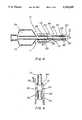
- FIG. 1shows a partial cross-sectional view of a catheter and strain relief device of a prior art configuration showing the catheter in perspective and the strain relief device in cross-section;
- FIG. 2is an enlarged view of the area labeled "II" in FIG. 1;
- FIG. 3is a partial cross-sectional view of a first preferred embodiment of a strain relief device of the present invention showing the flow pattern of bonding material placed in between a catheter tube and a strain relief device in accordance with the principles of the present invention, the catheter and the bonding material being shown in perspective and the strain relief device being shown in cross-section;
- FIG. 4shows a partial cross-sectional view of a catheter incorporating a second preferred embodiment of a strain relief device formed in accordance with the principles of the present invention with the catheter being shown in perspective and the strain relief device being shown in cross-section;
- FIG. 5is an enlarged view of area labeled "V" as shown is FIG. 4;
- FIG. 6is a partial cross-sectional view, showing the capillary flow pattern of bonding material between the catheter tube and the strain relief device of the second preferred embodiment of the invention as shown in FIG. 5, the catheter and the bonding material being shown in perspective and the strain relief device being shown in partial cross-section.
- a prior art catheter 10 including a hub 11 and a tube 12is shown in conjunction with a cross-sectional representation of a prior art strain relief device 13.
- a prior art catheter such as catheter 10can be formed by placing a sectionof a tube 12 into a mold (not shown) which has been designed to form a hub 11, and allowing molten plastic material to fill the mold and surround theportion of the tube 12 inserted therein. In the molding process, molten plastic forming hub 11 will surround the proximal end of tube 12 and form a junction 14 between the tube 12 and the hub 11.
- Tube 12is usually formed of a fairly soft flexible polyurethane having a relatively low durometer hardness.
- Hub 11is usually formed of a more rigid polyurethane having a lower melting point than the material used fortube 12, but a relatively higher durometer hardness.
- the junction 14therefore consists of a relatively rigid material (the hub 11) adjoined with a relatively flexible material (the tube 12).
- the prior art strain relief device 13is preferably formed by an injection molding process and is formed of a material which has a flexibility which is less than that of the tube 12, yet greater than that of the hub 11.
- Thestrain relief device 13is also formed to include a lumen 15 therethrough which is of a diameter sufficiently greater than the outer diameter of tube 12 so as to allow uninhibited passage of the tube 12 therethrough forease of assembly.
- the lumen 15is formed to be substantially the same diameter as the outer diameter of the nose portion 33 of hub 11 which is to be inserted therein. Prior to the placement of nose 33 into the lumen 15, it is generally the practice in the prior art to place a bonding material, such as a solvent, about the nose 33 in order to insure that the strain relief device becomes permanently attached thereto when connected.
- a bonding materialsuch as a solvent
- the prior art catheter tube 12extends through lumen 15 beyond distal portion 16 of prior art strain relief device 13.
- tube 12is allowed substantial play within the lumen 15 in order to simplify insertion of the strain relief device 13 over the tube 12 during assembly.
- An axial pulling force between the hub 11 and the tube12, directed along central axis 17,would not be resisted in any manner by the prior art strain relief device 13 attached to the catheter 10 in the manner shown in FIG. 2.
- a bending forces directed laterally to axis 17would cause tube 12 to contact the lumen 15 and would thereafter be resisted by the strain relief device 13.
- the strain relief device 13isdesigned of a durometer hardness and of an overall geometry which provides a predetermined flexibility and deflection in response to lateral forces applied thereto as a result of the bending of tube 12.
- the design of device 13is calculated to provide predetermined flexibility and deflection characteristics which operate to resist kinking or collapse of the tube 12 at the hub/tube junction 14.
- the catheter 10(as shown in FIG. 1) will fail as a result of axial pull forces when the strength of the molded hub/tube junction 14 is overcome.
- the above described molding problemssuch as water accumulation in the molding material, have rendered it difficult in the past to maintain uniform strength in the hub/tube junction 14 using prior manufacturing methods. Since it is extremely important (due to potentially disastrous effects of failure of a catheter to a patient) to have each and every catheter 10 meet minimum specifications, there is necessarily a low tolerance in the medical art for variations in the minimum pull strength of the hub/tube junction 14 of a catheter.
- a first preferred embodiment of the present inventionincludes the addition of a bonding material 18 to the lumen 15 of a prior art strain relief device 13.
- the bonding material 18may be of any well known type adhesive or solvent but is preferably a solvent such as tetrahydoflourane (THF) or cyclohexanone, or other solvent type bonding materials or combinations thereof which are known to be useful for bondingpolymeric materials.
- THFtetrahydoflourane
- cyclohexanonecyclohexanone
- the bond between the hub 11 and/or tube 12, and the strain relief devicesbe formed in any well known manner, including but not limited to, welding, friction bonding, chemical bonding (of any sort), electromagneticwave heating, etc.
- the first embodiment of the present invention as shown in FIG. 3increases the pull strength of devices on which it is employed in a manner which is extremely desirable for a number of applications and intended uses.
- the first embodiment of the inventiondue to the fixation of the device 13 to the tube 12, has flexibility and deflection characteristics different from those of the prior art catheter 10 and strain relief device13 (as shown in FIG. 1). Since bending forces applied to tube 12 are resisted by the strain relief device 13 (as shown in FIG. 3) differently than the strain relief device (as shown in FIG. 1 due to the presence of the redundant bond 19 formed by the bonding material 18, the first embodiment of the present invention is better suited for particular uses than prior art devices.
- FIG. 4shows a second preferred embodiment of the present invention which not only includes a redundant bond for increasing the pull strength of thecatheter 10 in the manner as shown in FIG. 3 with respect to the first embodiment of the invention, but also includes a structural design which insures that the bond material will form into a uniform, repeatable, bilaterally symmetrical bond.
- the second embodiment of the inventionis designed to have predetermined flexibility and deflection characteristics against bending forces which take into account the presence of the redundant bond to inhibit kinking of the tube 12.
- the flexibility and deflection characteristics of the second embodiment ofthe present inventionremain similar to the characteristics of the prior art strain relief device 13 when used without a redundant bond (i.e., in the manner as is shown in FIG. 1).
- the strain relief device 20 of the second embodiment of the present inventionis preferably formed of a polyurethanematerial having a durometer hardness similar to that of the prior art strain relief device 13 (i.e., a durometer hardness somewhere between the durometer hardness of the hub 11 and the tube 12).
- the device 20is formedin a conical elongated shape, the proximal portion 21 having the largest diameter, with the diameter decreasing in the direction of the central portion 22 and the distal portion 23 thereof.
- the device 20includes a lumen 24 which passes through its entire length.
- the lumen 24forms generally three sections of varying diameters; a proximal section 25 of a diameter which is substantially equal to the outer diameter of the nose portion 33 of hub 11 which is to be inserted therein; a central section 26 which is of a diameter substantially larger than the outer diameter of the tube 12; and, a distal section 27 having a diameter which is only slightly larger than the outer diameter of tube 12.
- the size of the distal lumen section 27is predetermined to form an annularshaped cavity 28 between its inner surface and the outer surface of the tube 12 when tube 12 is inserted therein. If desired, a distal end 30 of the distal section 27 of the lumen 24 may be formed into a funnel shaped opening 29 to aid in dispersement of bonding material in the manner as will be explained below.
- the geometry of the annular cavity 28is designed to allow for a bond between the tube 12 and the distal section 27 of the lumen 24 such that the axial pull to separation force resistible between the hub 11 and the tube 12 will be on the order of the axial pull to separation force of the tube 12 itself, which is the ultimate limiting factor of the strength of the catheter 10.
- annular cavity 28is designed to correlate with the viscosity of the bonding material 31 (as shown in FIG. 6) so that capillary forces resulting from the placement of bonding material 31 into the cavity 28 will pull the bonding material into a complete, even, uniform bonding pattern which at least forms a bond having a radially symmetrical distal end surface about the tube 12 at the distal end 30 of device 20 and which preferably entirely fills and corresponds precisely with the geometry of the annular cavity 28.
- the overall geometry of the device 20 and its lumen 24is designedso that deflection and flexibility characteristics remain the same or similar to predetermined characteristics for similar type strain relief devices (such as device 13 as shown in FIG. 1). These flexibility and deflection characteristics are important to maintain in order to avoid abrupt curvature changes (kinking) of the tube and to insure predictable and uniform (or uniformly changing) curvatures along the entire hub/tube junction 14 during its subjection to bending forces.
- the cavity 28is properly referred to as a "wicking cavity” since it in effect is capable of pulling bonding material thereinto through wicking orcapillary forces to completely and evenly fill the cavity 28 to form a uniform bilaterally symmetrical bond.
- the geometry of cavity 28is defined by inner surface 32 of the distal section 27 of the lumen 24, and the outer surface of the portion of tube 12 directly most adjacent thereto.
- the funnel 29functions to allow placement of bonding material 31 thereinto and allows the bonding material to flow at least partially around the tube12 before entering cavity 28.
- the bonding material 31is drawn into cavity 28 by capillary action and is pulled in all directions until it completelyand uniformly fills the cavity 28. Since the central section 26 of the lumen 24 is of a substantially larger diameter than that of distal section27 which forms cavity 28, capillary forces tend to inhibit any bonding material 31 from entering into the central section 26 of the lumen 24.
- the first preferred embodiment of the present invention as shown in FIG. 3may be manufactured in the following manner.
- a prior art type catheter 10is constructed by forming a tube 12 andinserting the proximal end thereof into a hub mold a sufficient distance toallow molten plastic to be injected thereinto.
- the molten plasticsurroundsthe portion of the tube 12 located therein and forms a bond between the hub11 and the tube 12.
- a bonding materialsuch as a solvent may be placed on nose portion 33 of the hub 11, and the prior art type strain relief device 13 is placed thereabout, such as by inserting the device 13 over tube 12 and sliding it down to the hub 11 until the proximal portion thereof is forced over the nose 33 with the solvent forming a permanent bond therebetween.
- the first embodiment of the present inventioncan be formed in an identical manner as the prior art, if desired, except thatonce the prior art strain relief device 13 is in place, the present invention manufacturing process further includes the step of forming a bond, such as by introducing a bonding material 18, into the distal end oflumen 15 of the strain relief device 13 to form the redundant bond 19 between the strain relief device and the tube 12.
- the second preferred embodiment of the present inventionis also manufactured in a manner similar to the prior art device as shown in FIG. 1, except that a strain relief device such as device 20 as shown in FIG. 4is inserted over the tube 12 and permanently bonded to the nose 33 of hub 11. Thereafter, bonding material 31 can be placed in the funnel shaped opening 29 (if present, or directly into cavity 28 if not) and allowed to flow around the catheter tube 12 and drawn into the wicking cavity 28 by capillary forces. Capillary forces then continue to cause bonding material31 to spread uniformly and evenly around tube 12 to form a bilaterally symmetrical redundant bond 34 between tube 12 and distal section 27 of thestrain relief device 20.
- the bonding material 31is held by capillary action in the cavity 28 and inhibited from passing into the central section 26, thus insuring the desired uniform annular shape of redundant bond 34.
- the geometry of the annular cavity 28will need to be adjusted according to the viscosity and strength of the bonding material used.
- a solventsuch as THF
- the diameter of the distal section 27 of the lumen 24be sized to approximately two thousandths of an inch larger than the maximum anticipated diameter of the catheter tube 12.
- the diameter of the distal section 27 of the lumen 24 of the strain relief device 20would preferably be formed to approximately thirty-six thousandths of an inch. This would insure that a spacing always existed between the catheter tube 12 and the distal section 27 of at least one thousandths of an inch on each side, yet never more than three thousandths of an inch. This would insure good capillary action between the cavity and the THF.
- the length of cavity 28 along distal section 27 of the lumen 24, for a 2.5 French size catheter 10should be in the range of twenty to sixty thousandths of an inch when using a solvent bonding material in order to insure sufficient bond strength. It is important to understand that the length of cavity 28 should be limited to only the distal portion 23 of thedevice 20 in order to avoid any negative effect on the flexibility and deflection characteristics thereof due to the presence of bond 34. Further, when using a solvent bonding material, the length of bond cavity 28 must also be limited in order to avoid entrapment of solvent in a manner which prevents proper evaporation (called "flashing") of componentsof the solvent in the bonding process. Otherwise, the excessive length of cavity 28 may prevent proper "flashing" and result in the trapped unevaporated solvent components degradating the plastic of the catheter tube 12 and device 20, inevitably compromising the structural integrity ofthe catheter 10.
- the redundant bond 19 of the first preferred embodiment of the inventionsignificantly increases pull to separation forces required to separate hub/tube junction 14 over prior art catheter designs (such as exemplified in FIG. 1). Similarly, substantially greater pull to separation forces are achieved with the second preferred embodiment of theinvention (as shown in FIGS. 4-6).
- the flexibility and deflection characteristics of the strain relief device 20 of the second embodiment of the present inventionremain substantially similar to the characteristics of the prior art strain relief device 13 (without a redundant bond as shown in FIG. 1). This is due to the fact that the strain relief device 20 is formed with the central section 26 of the lumen 24 thereof of a substantially increased diameter over the diameter of lumen 15 of the prior art device 13.
- the enlarged diameter of the central section 26 of device 20, combined with the design of the distal portion 23 thereof, and the inclusion of redundant bond 34,have a net result of generating flexibility and deflection characteristics in thestrain relief device 20 which are similar to the deflection and flexibilitycharacteristics of the prior art strain relief device 13 (as used in FIG. 1).
- central section 26and distal section 27 of lumen 24perform two functions; first, to form a wicking cavity 28 which draws bonding material 31 into a uniform annular bonding pattern 34, (which is prevented through capillary action from moving into the central section 26); and second, to generate flexibility and deflection characteristics similar to those demonstrated by the prior art strain relief device 13 (as shown in FIG. 1).
Landscapes
- Health & Medical Sciences (AREA)
- Life Sciences & Earth Sciences (AREA)
- Biophysics (AREA)
- Pulmonology (AREA)
- Engineering & Computer Science (AREA)
- Anesthesiology (AREA)
- Biomedical Technology (AREA)
- Heart & Thoracic Surgery (AREA)
- Hematology (AREA)
- Animal Behavior & Ethology (AREA)
- General Health & Medical Sciences (AREA)
- Public Health (AREA)
- Veterinary Medicine (AREA)
- Media Introduction/Drainage Providing Device (AREA)
Abstract
Description
This is a continuation of copending application Ser. No. 07/642,485 filed on Jan. 19, 1991 now abandoned.
1. Field of the Invention
This invention relates generally to strain relief devices for tubular members. More specifically, this invention relates to improved strain relief devices for use at the hub/tube junction of a catheter assembly. Even more specifically, the present invention relates to improvements in strain relief devices for increasing the connection strength of a hub/tube junction of a catheter assembly.
2. Brief Description of the Prior Art
Catheters of the prior art are generally formed of three main elements. A first element is generally an elongated catheter tube (tube) which is intended to be of a sufficient length such that a distal end thereof may pass into a patient while the proximal end thereof remains outside the patient so as to allow the delivery and/or removal of fluids from the patient's body. A second element of the catheter is generally referred to as a catheter hub (hub) which is generally affixed to the proximal end of the tube to form a hub/tube junction. The hub is used to allow connection of a fluid delivery or fluid reception system to the catheter in a manner and for purposes commonly known in the prior art.
When strain relief is required between the hub and tube, the hub and tube constitute merely a subassembly of the catheter, and a strain relief device is included as a third element thereof. The strain relief device is generally attached over the hub/tube junction in such a way as to cause part of the strain relief device to be affixed to the hub while another part thereof encompasses a portion of the tube (See for example, prior art FIG. 1 of the present disclosure).
Strain relief devices of the above described type have been used in the past to prevent the collapse of a tube when it is subjected to lateral (bending) forces. The strain relief device is designed to prevent non-uniform curvature, i.e., "kinking" of the tube of the catheter at or near the hub/tube junction. Strain relief devices of this type are usually attached to a catheter at a point where the tube thereof forms a junction with the more rigid hub structure. This placement of the strain relief device prevents bending forces from concentrating at the hub/tube junction due to the non-uniform flexibility thereacross. The strain relief device is basically designed to spread bending forces along a significant length of the tube and away from the hub/tube junction.
Although strain relief devices have in the past functioned adequately to relieve the strain of bending forces at a hub/tube junction, they have nevertheless been less than adequate to aid in strengthening the junction against axial forces, i.e., forces along the longitudinal axis of the tube which tend to pull the tube away from the hub. Such axial forces can arise either during normal use, or during any number of common accidents or mishaps. Forces exceeding the strength of the hub/tube junction of the catheter can lead to failure thereof, and possibly disastrous consequences for a patient who may heavily rely on its proper functioning.
There exists therefore a need in the art to develop a strain relief device which not only functions to relieve strain at a hub/tube junction due to bending forces, but also function to relieve strain on a hub/tube junction due to axial hub/tube separation forces (axial pulling forces).
Manufacturing of prior art catheters which include a hub/tube junction has generally included either a solvent bond between the hub and the tube, or an insert molding process in which the tube is placed into a hub mold, and molten plastic is allowed to flow into the mold around the catheter to form and secure the hub to the tube.
There is ordinarily no flange, anchor, threading or other securing means used to insure a more secure connection between the tube and the hub due to significant increases in the time and expense of manufacture. As a result, the junction generally formed by the hub as it is melted about the tube is the only bond on prior art catheters which resists axial separation forces.
Inconsistencies may arise in the above molding process which may affect the ability of the molten plastic to adhere to the tube to form the bond between the hub and tube. Consequently, the bond at the hub/tube junction may be insufficiently strong to effectively resist axial separation forces. The inconsistencies may develop in the manufacturing process in several ways. For example, moisture content in the raw hub material may arise, thus inhibiting bonding between the molten plastic and the tube. Also, since many raw hub materials are hydroscopic, they often absorb and are affected by water in a way adverse to the strength of the hub/tube bond.
Further, worn molds which have been used to manufacture a large number of catheters may fit together in a less than perfect manner, allowing flash material to be formed at the parting line of the hub molds. Flash generated in certain areas of the hub of the catheter due to mold wear has been known to cause the catheter to fail prematurely when subjected to axial forces.
Other problems and/or parameters in the molding process, such as molding pressure, temperature and mold gate size also have an effect on the bond formed between the tube and the hub during manufacture.
There exists therefore a need to develop a manufacturing process which can compensate for, and even overcome, possible weaknesses in the hub/tube junction due to inconsistencies in the hub molding step of the manufacturing process.
Catheters of the above described nature are routinely manufactured in large quantities, and are routinely tested for the strength of the bond of the hub/tube junction in order to verify that a predetermined minimum allowable axial force, called a "minimum allowable pull to separation force" is met by the manufactured catheter. For reasons of safety it is critical for certain intended uses of the catheters that no single catheter of a manufactured lot fail when subjected to forces at or below this minimum allowable pull force. A test revealing a substandard catheter therefore, will cause the entire lot of catheters from which it was a part to be scraped, resulting in a significant loss of time and money to the manufacturer.
There exists therefore a further need to develop a catheter and a manufacturing process therefore in which the catheters consistently and uniformly meet minimum pull strength requirements.
It is an object of the present invention to provide a strain relief device which is capable of resisting both bending and axial forces generated at a hub/tube junction of a catheter.
It is another object of the present invention to provide a strain relief device which can be redundantly bonded about a hub/tube junction of a catheter to prevent concentration of bending forces which would tend to cause kinking of the tube, and at the same time resist axial forces which would tend to cause a separation of the tube from the hub.
It is another object of the present invention to provide a strain relief device which is symmetrically bonded to a tube of a catheter in such a manner that stresses due to axial pulling forces are evenly distributed around the tube in such a manner that premature cracking and/or failure due to uneven strain in the tube is avoided.
It is also an object of the present invention to provide a strain relief device which is capable of drawing bonding material between the strain relief device and the tube into a uniformly and symmetrically-shaped bonding cavity through capillary action.
It is another object of the present invention to provide a strain relief device as described above which provides added resistance against axial pull forces at the hub/tube junction, while at the same time maintains predetermined flexibility and deflection characteristics for resisting the concentration of bending forces at the hub/tube junction.
It is another object of the present invention to provide a strain relief device as described above which is also inexpensive and an integral part of a consistent and repeatable catheter manufacturing process.
Briefly, and in general terms, the present invention provides a strain relief device and method of manufacturing the same, which assists in resisting bending forces to avoid kinking of the tube at a hub/tube junction of a catheter, while at the same time assists in the resistance of axial pull forces between the hub and the tube to avoid separation thereof during use.
In a first preferred embodiment, by way of example and not necessarily by way of limitation, a strain relief device (device) made in accordance with the principles of the present invention includes an elongate body formed of elastomeric material having a lumen formed therethrough along its entire length. The strain relief device lumen (lumen) may be divided into proximal, central and distal sections which may each be of different and/or varying diameters. The device is placed about a hub/tube junction of the catheter in such a manner that a nose portion of the hub is located in the proximal section of the lumen of the device, and the tube passes through the central and distal lumen sections to extend beyond the distal end of the device. The distal section of the lumen may then be bonded to the tube to form a second, redundant bond between the strain relief device and the tube.
In a second preferred embodiment of the present invention, the central section of the lumen of the strain relief device as described above is formed of a diameter significantly greater than the outer diameter of the tube, and the distal section of the lumen is formed of a diameter which is only slightly greater than the outer diameter of the tube. When the strain relief device is placed about the hub/tube junction of a catheter, an elongated annular cavity is formed between the distal section of the lumen and the outer surface of the tube. The cavity is designed so that when bonding material of a predetermined viscosity is added thereinto it will be moved by capillary action to fill the cavity in a uniform, bilaterally symmetrical bonding pattern.
A distal end of the distal section of the lumen of this second embodiment of the strain relief device may be formed into a funnel-shaped opening if desired, in order to assist in the placement of bonding material adjacent to the cavity and to facilitate the flow of the bonding material around the tube and into the cavity.
A catheter including the first preferred embodiment of the strain relief device of the present invention can be manufactured by a preferred process which may include forming a hub/tube junction by insert molding a tube to a hub as described above, and then assembling the strain relief device over the tube. The lumen of the strain relief device is formed of a proximal section sized to snugly attach to the nose portion of the hub, and a central and distal section, sized to allow passage of the tube therethrough. Bonding material, such as solvent, is used to form a permanent bond between the strain relief and the tube and/or to form a bond between the strain relief and the hub.
In second preferred method of manufacture the present invention, a central section of the strain relief lumen is sized to a diameter substantially greater than the outer diameter of the tube, and contrarily, the distal section of the lumen is sized to a diameter only slightly greater than the outer diameter of the tube. The distal section of the lumen may have the distal end thereof formed into a funnel shape to assist the flow of bonding material into the cavity as described in conjunction with the first embodiment if so desired.
The tube of the catheter is then inserted through the lumen of the strain relief device and a bonding material such as a solvent is placed on the nose portion of the hub. The proximal section of the lumen of the strain relief device is then affixed to the hub nose to form a first permanent bond. More bonding material is then dispensed into the cavity through the funnel-shaped distal end of the strain relief device (if present) and allowed through capillary action to flow around the tube and into the cavity. This forms a second (redundant) permanent bond, independent and spaced apart from the first permanent bond at the nose of the hub. The formation of the central section of the lumen of the strain relief device to a diameter significantly larger than that of the distal lumen section operates to prevent bonding material from flowing away from or out of the cavity. The bonding material is held in the distal section of the lumen by the capillary forces caused by the design of the cavity.
The above and other objects and advantages of the present invention will become apparent from the following more detailed description, when taken in conjunction with the accompanying drawings in which like elements are identified with like numerals throughout.
FIG. 1 shows a partial cross-sectional view of a catheter and strain relief device of a prior art configuration showing the catheter in perspective and the strain relief device in cross-section;
FIG. 2 is an enlarged view of the area labeled "II" in FIG. 1;
FIG. 3 is a partial cross-sectional view of a first preferred embodiment of a strain relief device of the present invention showing the flow pattern of bonding material placed in between a catheter tube and a strain relief device in accordance with the principles of the present invention, the catheter and the bonding material being shown in perspective and the strain relief device being shown in cross-section;
FIG. 4 shows a partial cross-sectional view of a catheter incorporating a second preferred embodiment of a strain relief device formed in accordance with the principles of the present invention with the catheter being shown in perspective and the strain relief device being shown in cross-section;
FIG. 5 is an enlarged view of area labeled "V" as shown is FIG. 4; and
FIG. 6 is a partial cross-sectional view, showing the capillary flow pattern of bonding material between the catheter tube and the strain relief device of the second preferred embodiment of the invention as shown in FIG. 5, the catheter and the bonding material being shown in perspective and the strain relief device being shown in partial cross-section.
As shown in FIG. 1, aprior art catheter 10 including a hub 11 and atube 12 is shown in conjunction with a cross-sectional representation of a prior artstrain relief device 13.
A prior art catheter such ascatheter 10 can be formed by placing a sectionof atube 12 into a mold (not shown) which has been designed to form a hub 11, and allowing molten plastic material to fill the mold and surround theportion of thetube 12 inserted therein. In the molding process, molten plastic forming hub 11 will surround the proximal end oftube 12 and form ajunction 14 between thetube 12 and the hub 11.
The prior artstrain relief device 13 is preferably formed by an injection molding process and is formed of a material which has a flexibility which is less than that of thetube 12, yet greater than that of the hub 11.Thestrain relief device 13 is also formed to include alumen 15 therethrough which is of a diameter sufficiently greater than the outer diameter oftube 12 so as to allow uninhibited passage of thetube 12 therethrough forease of assembly.
At the proximal end of thestrain relief device 13, thelumen 15 is formed to be substantially the same diameter as the outer diameter of thenose portion 33 of hub 11 which is to be inserted therein. Prior to the placement ofnose 33 into thelumen 15, it is generally the practice in the prior art to place a bonding material, such as a solvent, about thenose 33 in order to insure that the strain relief device becomes permanently attached thereto when connected.
As best seen in FIG. 2, the priorart catheter tube 12 extends throughlumen 15 beyonddistal portion 16 of prior artstrain relief device 13. Ascan be seen,tube 12 is allowed substantial play within thelumen 15 in order to simplify insertion of thestrain relief device 13 over thetube 12 during assembly. An axial pulling force between the hub 11 and the tube12, directed along central axis 17, would not be resisted in any manner by the prior artstrain relief device 13 attached to thecatheter 10 in the manner shown in FIG. 2. However, a bending forces directed laterally to axis 17 would causetube 12 to contact thelumen 15 and would thereafter be resisted by thestrain relief device 13. Thestrain relief device 13 isdesigned of a durometer hardness and of an overall geometry which provides a predetermined flexibility and deflection in response to lateral forces applied thereto as a result of the bending oftube 12. The design ofdevice 13 is calculated to provide predetermined flexibility and deflection characteristics which operate to resist kinking or collapse of thetube 12 at the hub/tube junction 14.
Since the prior artstrain relief device 13 has no effect on axial forces throughtube 12, the catheter 10 (as shown in FIG. 1) will fail as a result of axial pull forces when the strength of the molded hub/tube junction 14 is overcome. The above described molding problems, such as water accumulation in the molding material, have rendered it difficult in the past to maintain uniform strength in the hub/tube junction 14 using prior manufacturing methods. Since it is extremely important (due to potentially disastrous effects of failure of a catheter to a patient) to have each and everycatheter 10 meet minimum specifications, there is necessarily a low tolerance in the medical art for variations in the minimum pull strength of the hub/tube junction 14 of a catheter. Due to the high performance and reliability requirements of medical catheters, a significant amount of scrap can be generated during the prior art manufacturing process if it becomes necessary to scrap an entire lot ofcatheters 10 as a result of a single sample catheter from the lot failing to meet a minimum acceptable pull strength.
As shown in FIG. 3, a first preferred embodiment of the present invention includes the addition of abonding material 18 to thelumen 15 of a prior artstrain relief device 13. Thebonding material 18 may be of any well known type adhesive or solvent but is preferably a solvent such as tetrahydoflourane (THF) or cyclohexanone, or other solvent type bonding materials or combinations thereof which are known to be useful for bondingpolymeric materials. Further, although not elaborated on in the descriptionof the preferred embodiments, it is anticipated by the present invention that the bond between the hub 11 and/ortube 12, and the strain relief devices be formed in any well known manner, including but not limited to, welding, friction bonding, chemical bonding (of any sort), electromagneticwave heating, etc.
The addition ofredundant bond 19 into thecatheter 10 which includes priorart strain relief device 13 (as shown in FIG. 3) causes a significant increase in the axial pull strength of thecatheter 10 over prior art designs.
The first embodiment of the present invention as shown in FIG. 3 increases the pull strength of devices on which it is employed in a manner which is extremely desirable for a number of applications and intended uses.
Also the first embodiment of the invention, due to the fixation of thedevice 13 to thetube 12, has flexibility and deflection characteristics different from those of theprior art catheter 10 and strain relief device13 (as shown in FIG. 1). Since bending forces applied totube 12 are resisted by the strain relief device 13 (as shown in FIG. 3) differently than the strain relief device (as shown in FIG. 1 due to the presence of theredundant bond 19 formed by thebonding material 18, the first embodiment of the present invention is better suited for particular uses than prior art devices.
FIG. 4 shows a second preferred embodiment of the present invention which not only includes a redundant bond for increasing the pull strength ofthecatheter 10 in the manner as shown in FIG. 3 with respect to the first embodiment of the invention, but also includes a structural design which insures that the bond material will form into a uniform, repeatable, bilaterally symmetrical bond. Further, the second embodiment of the invention is designed to have predetermined flexibility and deflection characteristics against bending forces which take into account the presence of the redundant bond to inhibit kinking of thetube 12. Thus, the flexibility and deflection characteristics of the second embodiment ofthe present invention remain similar to the characteristics of the prior artstrain relief device 13 when used without a redundant bond (i.e., in the manner as is shown in FIG. 1).
As shown in FIGS. 4 and 5, thestrain relief device 20 of the second embodiment of the present invention is preferably formed of a polyurethanematerial having a durometer hardness similar to that of the prior art strain relief device 13 (i.e., a durometer hardness somewhere between the durometer hardness of the hub 11 and the tube 12). Thedevice 20 is formedin a conical elongated shape, theproximal portion 21 having the largest diameter, with the diameter decreasing in the direction of thecentral portion 22 and thedistal portion 23 thereof.
Thedevice 20 includes alumen 24 which passes through its entire length. Thelumen 24 forms generally three sections of varying diameters; aproximal section 25 of a diameter which is substantially equal to the outer diameter of thenose portion 33 of hub 11 which is to be inserted therein; acentral section 26 which is of a diameter substantially larger than the outer diameter of thetube 12; and, adistal section 27 having a diameter which is only slightly larger than the outer diameter oftube 12.
The size of thedistal lumen section 27 is predetermined to form anannularshaped cavity 28 between its inner surface and the outer surface of thetube 12 whentube 12 is inserted therein. If desired, adistal end 30 of thedistal section 27 of thelumen 24 may be formed into a funnel shapedopening 29 to aid in dispersement of bonding material in the manner as will be explained below.
The geometry of theannular cavity 28 is designed to allow for a bond between thetube 12 and thedistal section 27 of thelumen 24 such that the axial pull to separation force resistible between the hub 11 and thetube 12 will be on the order of the axial pull to separation force of thetube 12 itself, which is the ultimate limiting factor of the strength of thecatheter 10.
Also, the geometry ofannular cavity 28 is designed to correlate with the viscosity of the bonding material 31 (as shown in FIG. 6) so that capillary forces resulting from the placement ofbonding material 31 into thecavity 28 will pull the bonding material into a complete, even, uniform bonding pattern which at least forms a bond having a radially symmetrical distal end surface about thetube 12 at thedistal end 30 ofdevice 20 and which preferably entirely fills and corresponds precisely with the geometry of theannular cavity 28.
Further, the overall geometry of thedevice 20 and itslumen 24 is designedso that deflection and flexibility characteristics remain the same or similar to predetermined characteristics for similar type strain relief devices (such asdevice 13 as shown in FIG. 1). These flexibility and deflection characteristics are important to maintain in order to avoid abrupt curvature changes (kinking) of the tube and to insure predictable and uniform (or uniformly changing) curvatures along the entire hub/tube junction 14 during its subjection to bending forces.
Thecavity 28 is properly referred to as a "wicking cavity" since it in effect is capable of pulling bonding material thereinto through wicking orcapillary forces to completely and evenly fill thecavity 28 to form a uniform bilaterally symmetrical bond.
As best shown in FIGS. 5 and 6, the geometry ofcavity 28 is defined byinner surface 32 of thedistal section 27 of thelumen 24, and the outer surface of the portion oftube 12 directly most adjacent thereto. Thefunnel 29 functions to allow placement ofbonding material 31 thereinto and allows the bonding material to flow at least partially around the tube12 before enteringcavity 28. Thebonding material 31 is drawn intocavity 28 by capillary action and is pulled in all directions until it completelyand uniformly fills thecavity 28. Since thecentral section 26 of thelumen 24 is of a substantially larger diameter than that of distal section27 which formscavity 28, capillary forces tend to inhibit anybonding material 31 from entering into thecentral section 26 of thelumen 24.
The first preferred embodiment of the present invention as shown in FIG. 3 may be manufactured in the following manner.
First, a priorart type catheter 10 is constructed by forming atube 12 andinserting the proximal end thereof into a hub mold a sufficient distance toallow molten plastic to be injected thereinto. The molten plastic surroundsthe portion of thetube 12 located therein and forms a bond between the hub11 and thetube 12.
Once theprior art catheter 10 is completely formed, a bonding material such as a solvent may be placed onnose portion 33 of the hub 11, and the prior art typestrain relief device 13 is placed thereabout, such as by inserting thedevice 13 overtube 12 and sliding it down to the hub 11 until the proximal portion thereof is forced over thenose 33 with the solvent forming a permanent bond therebetween.
As can be readily seen, the first embodiment of the present invention can be formed in an identical manner as the prior art, if desired, except thatonce the prior artstrain relief device 13 is in place, the present invention manufacturing process further includes the step of forming a bond, such as by introducing abonding material 18, into the distal end oflumen 15 of thestrain relief device 13 to form theredundant bond 19 between the strain relief device and thetube 12.
The second preferred embodiment of the present invention is also manufactured in a manner similar to the prior art device as shown in FIG. 1, except that a strain relief device such asdevice 20 as shown in FIG. 4is inserted over thetube 12 and permanently bonded to thenose 33 of hub 11. Thereafter,bonding material 31 can be placed in the funnel shaped opening 29 (if present, or directly intocavity 28 if not) and allowed to flow around thecatheter tube 12 and drawn into thewicking cavity 28 by capillary forces. Capillary forces then continue to cause bonding material31 to spread uniformly and evenly aroundtube 12 to form a bilaterally symmetricalredundant bond 34 betweentube 12 anddistal section 27 ofthestrain relief device 20.
Due to the enlarged diameter of thecentral section 26 oflumen 24, thebonding material 31 is held by capillary action in thecavity 28 and inhibited from passing into thecentral section 26, thus insuring the desired uniform annular shape ofredundant bond 34.
It is anticipated that the geometry of theannular cavity 28 will need to be adjusted according to the viscosity and strength of the bonding material used. For example, in the second preferred embodiment of the invention as shown in FIGS. 4-6, when a solvent such as THF is used, it isanticipated that the diameter of thedistal section 27 of thelumen 24 be sized to approximately two thousandths of an inch larger than the maximum anticipated diameter of thecatheter tube 12. Therefore, in the case of a specific size ofcatheter 10, such as a catheter of 2.5 French size, having atube 12 of approximately thirty-two thousandths plus or minus twothousandths of an inch in diameter, the diameter of thedistal section 27 of thelumen 24 of thestrain relief device 20 would preferably be formed to approximately thirty-six thousandths of an inch. This would insure thata spacing always existed between thecatheter tube 12 and thedistal section 27 of at least one thousandths of an inch on each side, yet never more than three thousandths of an inch. This would insure good capillary action between the cavity and the THF.
The length ofcavity 28 alongdistal section 27 of thelumen 24, for a 2.5French size catheter 10 should be in the range of twenty to sixty thousandths of an inch when using a solvent bonding material in order to insure sufficient bond strength. It is important to understand that the length ofcavity 28 should be limited to only thedistal portion 23 ofthedevice 20 in order to avoid any negative effect on the flexibility and deflection characteristics thereof due to the presence ofbond 34. Further, when using a solvent bonding material, the length ofbond cavity 28 must also be limited in order to avoid entrapment of solvent in a manner which prevents proper evaporation (called "flashing") of componentsof the solvent in the bonding process. Otherwise, the excessive length ofcavity 28 may prevent proper "flashing" and result in the trapped unevaporated solvent components degradating the plastic of thecatheter tube 12 anddevice 20, inevitably compromising the structural integrity ofthecatheter 10.
Theredundant bond 19 of the first preferred embodiment of the invention (as shown in FIG. 3) significantly increases pull to separation forces required to separate hub/tube junction 14 over prior art catheter designs (such as exemplified in FIG. 1). Similarly, substantially greater pull to separation forces are achieved with the second preferred embodiment of theinvention (as shown in FIGS. 4-6).
The flexibility and deflection characteristics of thestrain relief device 20 of the second embodiment of the present invention remain substantially similar to the characteristics of the prior art strain relief device 13 (without a redundant bond as shown in FIG. 1). This is due to the fact that thestrain relief device 20 is formed with thecentral section 26 of thelumen 24 thereof of a substantially increased diameter over the diameter oflumen 15 of theprior art device 13. The enlarged diameter of thecentral section 26 ofdevice 20, combined with the design of thedistal portion 23 thereof, and the inclusion ofredundant bond 34, have a net result of generating flexibility and deflection characteristics inthestrain relief device 20 which are similar to the deflection and flexibilitycharacteristics of the prior art strain relief device 13 (as used in FIG. 1).
It should be understood that the respective diameters of central section 26anddistal section 27 oflumen 24 perform two functions; first, to form awicking cavity 28 which drawsbonding material 31 into a uniformannular bonding pattern 34, (which is prevented through capillary action from moving into the central section 26); and second, to generate flexibility and deflection characteristics similar to those demonstrated by the prior art strain relief device 13 (as shown in FIG. 1).
It will be apparent from the foregoing that, while the particular shown embodiments of the invention relate to use of the invention with catheters, various other general uses of the invention in conjunction withother types of tubular devices are anticipated, including modifications to the particularly illustrated embodiments, without departing from the spirit and scope of the invention. Accordingly, it is not intended that the invention be limited in any manner, except as by the appended claims.
Claims (19)
1. A device for relieving strain concentration at a junction between a rigid member and a flexible member of a medical device, said strain relief device comprising:
a strain relief body having a proximal portion, a central portion, and a distal portion, said strain relief body forming a lumen therethrough, and the junction between the rigid member and the flexible member being positioned within said lumen,
means attaching said proximal portion of said strain relief body to the rigid member,
means attaching said distal portion of said strain relief body to the flexible member, and including a wicking cavity located between said distal portion and the flexible member, said wicking cavity including means for encouraging wicking of a bonding material therein, and said means attaching said distal portion of said strain relief body to the flexible member further including bonding material in said wicking cavity, and
means for discouraging wicking in said central portion,
whereby, said device inhibits strain concentrations due to lateral-type forces which tend to bend the flexible member at an angle relative to the rigid member, and due to axial pull forces which tend to separate the flexible member from the rigid member.
2. A strain relief device according to claim 1 wherein said means for discouraging wicking further includes a variation in the diameter of said lumen between said distal portion and said central portion.
3. A device according to claim 1 wherein said lumen is formed of a proximal section, a central section, and a distal section, said distal section being attachable to the flexible portion of the elongate member and said proximal section being attachable to the rigid portion of the elongate member.
4. A device according to claim 3 wherein said distal section of said lumen is formed of a diameter which is less than the diameter of said central section of said lumen.
5. A strain relief device according to claim 1 wherein said bonding material forms a bi-laterally symmetrical bond between said distal section of said lumen and the flexible portion of the elongate member.
6. A strain relief device according to claim 5 wherein said bonding material is a solvent.
7. A strain relief device according to claim 6 wherein said elongate member is a catheter and wherein said rigid portion is a catheter hub and said relatively flexible portion is a catheter tube.
8. A strain relief device according to claim 1 wherein said distal section of said lumen further includes a distal end, said distal end being conical in shape and forming a bonding material dispersion funnel which is in fluid flow connection with said wicking cavity and which aids in even dispersion of bonding material into said wicking cavity.
9. A strain relief device according to claim 8 wherein said dispersion funnel of said distal end of said lumen aids in bonding material flow around the flexible portion of the elongate member.
10. A strain relief device according to claim 8 wherein said bonding material forms a bond which is uniformly symmetrical about the tube end distal and of said device.
11. A strain relief device according to claim 1 wherein said central section of said lumen includes means for inhibiting the flow of bonding material from said distal section into said central section.
12. A strain relief device according to claim 1 wherein said means at said distal portion for attaching the flexible portion of the elongate member to said body includes bonding material, and further includes means for dispersing said bonding material into a controlled bonding pattern between said lumen and the flexible portion of the elongate member.
13. A strain relief device according to claim 1 wherein said means for attaching said distal portion of said lumen to the flexible portion of the elongate member includes means for forming a bi-laterally symmetrical bond between said distal portion of said body and the flexible portion of the elongate member.
14. A method of forming a strain relief device about a junction between a relatively rigid portion and a relatively flexible portion of an elongate member, said method comprising the steps of:
forming a strain relief device which includes a lumen therethrough, the lumen having a distal section, a central section, and a proximal section, the diameter of the distal section being smaller than the diameter of the central section.
inserting the elongate member through the lumen of the strain relief device until the junction between the relatively rigid portion and the relatively flexible portion of the elongate member rests within the lumen,
attaching the proximal section of the lumen to the relatively rigid portion of the elongate member, and
attaching the distal section of the lumen to the relatively flexible portion of the elongate member by permanently bonding the distal section to the relatively flexible portion by inserting bonding material into a cavity formed by the distal section and the relatively flexible portion and evenly distributing the bonding material therein through capillary action, and
discouraging bonding material from passing into the central section of the lumen through the aid of capillary action by inserting a bonding material into the cavity which is of a viscosity which will allow it to disperse by capillary action within the cavity, yet be inhibited in its dispersion in the central section of the lumen by capillary action due to the variation in the diameter of the lumen between the distal section and the central section thereof.
15. A method according to claim 14 wherein said step of permanently bonding the distal section of the lumen to the relatively flexible portion of the elongate member includes forming a bond having at least a radially symmetrical distal end surface which is formed about a distal end of the distal section of the device.
16. A method according to claim 14 wherein said step of forming a controlled bond pattern further includes forming a bi-laterally symmetrical bond pattern.
17. A method according to claim 14 wherein said step of inserting bonding material into the cavity includes inserting a solvent into the cavity.
18. A method according to claim 14 wherein said step of forming a cavity includes forming the distal section of the lumen to a diameter of approximately two thousandths of an inch greater than the outer diameter of the relatively flexible portion of the elongate member.
19. A method according to claim 14 wherein the elongate member is a catheter, the relatively rigid portion of the elongate member being a catheter hub and the relatively flexible portion of the elongate member being a catheter tube, and the steps of attaching the proximal and distal sections of the lumen to the elongate member includes attaching the proximal section of the lumen to the hub and attaching the distal section of the lumen to the tube.
Priority Applications (1)
| Application Number | Priority Date | Filing Date | Title |
|---|---|---|---|
| US08/022,824US5330449A (en) | 1991-01-17 | 1993-02-24 | Catheter strain relief device |
Applications Claiming Priority (2)
| Application Number | Priority Date | Filing Date | Title |
|---|---|---|---|
| US64248591A | 1991-01-17 | 1991-01-17 | |
| US08/022,824US5330449A (en) | 1991-01-17 | 1993-02-24 | Catheter strain relief device |
Related Parent Applications (1)
| Application Number | Title | Priority Date | Filing Date |
|---|---|---|---|
| US64248591AContinuation | 1991-01-17 | 1991-01-17 |
Publications (1)
| Publication Number | Publication Date |
|---|---|
| US5330449Atrue US5330449A (en) | 1994-07-19 |
Family
ID=24576763
Family Applications (1)
| Application Number | Title | Priority Date | Filing Date |
|---|---|---|---|
| US08/022,824Expired - LifetimeUS5330449A (en) | 1991-01-17 | 1993-02-24 | Catheter strain relief device |
Country Status (1)
| Country | Link |
|---|---|
| US (1) | US5330449A (en) |
Cited By (57)
| Publication number | Priority date | Publication date | Assignee | Title |
|---|---|---|---|---|
| US5534287A (en)* | 1993-04-23 | 1996-07-09 | Schneider (Europe) A.G. | Methods for applying an elastic coating layer on stents |
| EP0801954A1 (en)* | 1996-04-19 | 1997-10-22 | Becton, Dickinson and Company | Catheter with stress distribution fingers |
| EP0813884A3 (en)* | 1996-06-19 | 1998-01-07 | Becton, Dickinson and Company | Medical device having a connector portion with an improved surface finish |
| US5755702A (en)* | 1994-04-21 | 1998-05-26 | Novoste Corporation | Adjustable angular sheath introducer |
| US5772639A (en)* | 1994-02-18 | 1998-06-30 | Merit Medical Systems, Inc. | Total alimentary nutrition catheter apparatus with means for subcutaneous delivery of anesthetic agent or other fluid medicament |
| US5797886A (en)* | 1994-02-18 | 1998-08-25 | Merit Medical Systems, Inc. | Catheter apparatus with means for subcutaneous delivery of anesthetic agent or other fluid medicament |
| US5817072A (en)* | 1994-02-18 | 1998-10-06 | Merit Medical Systems, Inc. | Central venous system catheter apparatus with means for subcutaneous delivery of anesthetic agent of other fluid medicament |
| US5830196A (en)* | 1995-09-21 | 1998-11-03 | Tyco Group S.A.R.L. | Tapered and reinforced catheter |
| WO1999016498A1 (en)* | 1997-10-01 | 1999-04-08 | Boston Scientific Limited | Percutaneous catheter with slip hub |
| WO1999044654A1 (en)* | 1998-03-06 | 1999-09-10 | Sherwood Services Ag | Catheter strain relief device |
| WO2000012165A1 (en)* | 1998-08-28 | 2000-03-09 | C. R. Bard, Inc. | Coupling and stabilization system for proximal end of catheter |
| US6068622A (en)* | 1998-02-10 | 2000-05-30 | Medtronic Inc. | Single piece hub/strain relief that can be injection molded over a shaft |
| USD433503S (en)* | 1999-04-02 | 2000-11-07 | C. R. Bard, Inc. | Proximal end catheter coupling hub |
| US6228073B1 (en) | 1998-12-15 | 2001-05-08 | Medtronic, Inc. | Angiography luer hub having wings proximal to the plurality of grips and strain relief |
| US6273404B1 (en) | 1995-06-05 | 2001-08-14 | Scimed Life Systems, Inc. | Method of making monolithic hub and strain relief |
| US6280423B1 (en) | 1998-02-24 | 2001-08-28 | Scimed Life Systems, Inc. | High flow rate dialysis catheters and related methods |
| US6332892B1 (en) | 1999-03-02 | 2001-12-25 | Scimed Life Systems, Inc. | Medical device with one or more helical coils |
| US6500285B2 (en) | 1999-08-23 | 2002-12-31 | Scimed Life Systems, Inc. | Method of making a catheter having interlocking ribbed bond regions |
| US6575959B1 (en) | 1999-12-27 | 2003-06-10 | Scimed Life Systems, Inc. | Catheter incorporating an insert molded hub and method of manufacturing |
| US6620202B2 (en) | 2001-10-16 | 2003-09-16 | Scimed Life Systems, Inc. | Medical stent with variable coil and related methods |
| US6656146B1 (en) | 1995-11-07 | 2003-12-02 | Scimed Life Systems, Inc. | Medical device with tail(s) |
| US6719804B2 (en) | 2001-04-02 | 2004-04-13 | Scimed Life Systems, Inc. | Medical stent and related methods |
| USD498844S1 (en) | 2003-08-29 | 2004-11-23 | C. R. Bard, Inc. | Dual lumen catheter winged bifurcation |
| US20050234499A1 (en)* | 2004-04-19 | 2005-10-20 | Scimed Life Systems, Inc. | Multi-lumen balloon catheter including manifold |
| US20050253389A1 (en)* | 2004-05-13 | 2005-11-17 | Schulte Gregory T | Medical tubing connector assembly incorporating strain relief sleeve |
| US20050283134A1 (en)* | 2004-06-22 | 2005-12-22 | Scimed Life Systems, Inc. | Catheter shaft with improved manifold bond |
| US6991614B2 (en) | 1995-11-07 | 2006-01-31 | Boston Scientific Scimed, Inc. | Ureteral stent for improved patient comfort |
| US20060200201A1 (en)* | 2005-02-16 | 2006-09-07 | Transoma Medical, Inc. | Implantable housing with catheter strain relief |
| WO2008022120A1 (en)* | 2006-08-16 | 2008-02-21 | Boston Scientific Limited | Removable hub assembly for medical device |
| US7387624B2 (en) | 2005-05-20 | 2008-06-17 | Medtronic, Inc. | Squeeze-actuated catheter connecter and method |
| US7537245B2 (en) | 2005-02-14 | 2009-05-26 | Medtronic, Inc. | Strain relief device and connector assemblies incorporating same |
| US20090157007A1 (en)* | 2007-12-18 | 2009-06-18 | Becton, Dickinson And Company | Anti-occlusion catheter adapter |
| US20090306606A1 (en)* | 2008-06-10 | 2009-12-10 | Angiodynamics, Inc | Catheter hub assembly with vascular access port |
| US7678101B2 (en) | 2005-05-20 | 2010-03-16 | Medtronic, Inc. | Locking catheter connector and connection system |
| US8177760B2 (en) | 2004-05-12 | 2012-05-15 | C. R. Bard, Inc. | Valved connector |
| US20130324974A1 (en)* | 2012-05-30 | 2013-12-05 | Fenwal, Inc. | Ensured component bonding |
| US9017308B2 (en) | 2002-05-21 | 2015-04-28 | Boston Scientific Scimed, Inc. | Insert molded hub and strain relief |
| US20150127043A1 (en)* | 2013-11-07 | 2015-05-07 | Medtronic Vascular, Inc. | Balloon Catheter Having a Pre-Positioned Refold Tool |
| WO2017074675A1 (en)* | 2015-10-28 | 2017-05-04 | Becton, Dickinson And Company | Extension tubing strain relief |
| US9707339B2 (en) | 2012-03-28 | 2017-07-18 | Angiodynamics, Inc. | High flow rate dual reservoir port system |
| US9713704B2 (en) | 2012-03-29 | 2017-07-25 | Bradley D. Chartrand | Port reservoir cleaning system and method |
| US9789279B2 (en) | 2014-04-23 | 2017-10-17 | Becton, Dickinson And Company | Antimicrobial obturator for use with vascular access devices |
| WO2017200830A1 (en)* | 2016-05-17 | 2017-11-23 | Q Holding Company | Tubing and junction assembly and method of making the same |
| US9895523B2 (en) | 2002-10-21 | 2018-02-20 | Angiodynamics, Inc. | Implantable medical device for improved placement and adherence in the body |
| US9956379B2 (en) | 2014-04-23 | 2018-05-01 | Becton, Dickinson And Company | Catheter tubing with extraluminal antimicrobial coating |
| USD828653S1 (en)* | 2016-12-14 | 2018-09-11 | Brandon Penland | Treatment applicator |
| US10166321B2 (en) | 2014-01-09 | 2019-01-01 | Angiodynamics, Inc. | High-flow port and infusion needle systems |
| US10376686B2 (en) | 2014-04-23 | 2019-08-13 | Becton, Dickinson And Company | Antimicrobial caps for medical connectors |
| US10413702B2 (en) | 2011-10-21 | 2019-09-17 | Boston Scientific Scimed, Inc. | Locking catheter hub |
| US10569069B2 (en) | 2016-12-14 | 2020-02-25 | Combat Comb, Llc | Applicator for treatments applied to animal skin |
| JPWO2021064853A1 (en)* | 2019-10-01 | 2021-04-08 | ||
| US11219705B2 (en) | 2014-07-08 | 2022-01-11 | Becton, Dickinson And Company | Antimicrobial coating forming kink resistant feature on a vascular access device |
| US11224720B2 (en) | 2015-09-09 | 2022-01-18 | B. Braun Melsungen Ag | Infusion systems, connectors for use with catheter devices, and related methods |
| US11357962B2 (en) | 2013-02-13 | 2022-06-14 | Becton, Dickinson And Company | Blood control IV catheter with stationary septum activator |
| US11666729B2 (en) | 2017-11-03 | 2023-06-06 | Hollister Incorporated | Methods of bonding components to polymeric substrates |
| US11986610B2 (en) | 2016-08-19 | 2024-05-21 | B. Braun Melsungen Ag | Needle assemblies and related methods |
| US12414719B2 (en) | 2016-08-15 | 2025-09-16 | Heraeus Medical Components Llc | Segmented electrode and method |
Citations (24)
| Publication number | Priority date | Publication date | Assignee | Title |
|---|---|---|---|---|
| US1115908A (en)* | 1913-03-19 | 1914-11-03 | Mark A Dees | Internal-bath apparatus. |
| US1569174A (en)* | 1921-01-27 | 1926-01-12 | Sanno & Hoskins Inc De | Hypodermic needle |
| US2236731A (en)* | 1939-03-08 | 1941-04-01 | Tokheim Oil Tank & Pump Co | Dispensing device |
| US3756235A (en)* | 1971-08-13 | 1973-09-04 | Burron Medical Prod Inc | Hypodermic syringe barrel and needle structure |
| US3784236A (en)* | 1971-10-05 | 1974-01-08 | Robroy Ind | Fitting for flexible conduits |
| US3807776A (en)* | 1971-05-21 | 1974-04-30 | L Bingham | Coupling collet and gland for metal to plastic conduit |
| US3920268A (en)* | 1973-02-13 | 1975-11-18 | Albert Stewing | Synthetic-resin tube assembly |
| US3920787A (en)* | 1971-07-02 | 1975-11-18 | Sloane Mfg Co R & G | Joint between tubular plastic articles and method of forming |
| US4035002A (en)* | 1974-12-30 | 1977-07-12 | Curtin Hoyt S | Pipe coupling |
| US4137117A (en)* | 1977-03-10 | 1979-01-30 | American Hospital Supply Corporation | Method of making a solvent-bonded joint |
| US4323065A (en)* | 1980-01-17 | 1982-04-06 | Baxter Travenol Laboratories, Inc. | Attachable connector for catheter |
| US4581024A (en)* | 1984-12-10 | 1986-04-08 | Becton, Dickinson And Company | Needle assembly |
| US4610674A (en)* | 1984-09-13 | 1986-09-09 | Terumo Kabushi Kaisha | Catheter introducing instrument |
| US4614188A (en)* | 1980-08-15 | 1986-09-30 | Seymour Bazell | Balloon catheter |
| US4673455A (en)* | 1984-05-10 | 1987-06-16 | Air, Ltd. | Self-centering sealing for electrode structure |
| US4819637A (en)* | 1987-09-01 | 1989-04-11 | Interventional Therapeutics Corporation | System for artificial vessel embolization and devices for use therewith |
| US4846174A (en)* | 1986-08-08 | 1989-07-11 | Scimed Life Systems, Inc. | Angioplasty dilating guide wire |
| US4913701A (en)* | 1988-10-06 | 1990-04-03 | Numed, Inc. | Balloon catheter and method of manufacturing the same |
| US4929235A (en)* | 1985-07-31 | 1990-05-29 | Universal Medical Instrument Corp. | Self-sealing percutaneous tube introducer |
| US4946466A (en)* | 1989-03-03 | 1990-08-07 | Cordis Corporation | Transluminal angioplasty apparatus |
| US4960412A (en)* | 1988-04-15 | 1990-10-02 | Universal Medical Instrument Corp. | Catheter introducing system |
| US4998923A (en)* | 1988-08-11 | 1991-03-12 | Advanced Cardiovascular Systems, Inc. | Steerable dilatation catheter |
| US5000611A (en)* | 1988-07-06 | 1991-03-19 | The United States Of America As Represented By The Secretary Of The Air Force | Attachment structure for cylindrical member |
| US5009391A (en)* | 1988-05-02 | 1991-04-23 | The Kendall Company | Valve assembly |
- 1993
- 1993-02-24USUS08/022,824patent/US5330449A/ennot_activeExpired - Lifetime
Patent Citations (24)
| Publication number | Priority date | Publication date | Assignee | Title |
|---|---|---|---|---|
| US1115908A (en)* | 1913-03-19 | 1914-11-03 | Mark A Dees | Internal-bath apparatus. |
| US1569174A (en)* | 1921-01-27 | 1926-01-12 | Sanno & Hoskins Inc De | Hypodermic needle |
| US2236731A (en)* | 1939-03-08 | 1941-04-01 | Tokheim Oil Tank & Pump Co | Dispensing device |
| US3807776A (en)* | 1971-05-21 | 1974-04-30 | L Bingham | Coupling collet and gland for metal to plastic conduit |
| US3920787A (en)* | 1971-07-02 | 1975-11-18 | Sloane Mfg Co R & G | Joint between tubular plastic articles and method of forming |
| US3756235A (en)* | 1971-08-13 | 1973-09-04 | Burron Medical Prod Inc | Hypodermic syringe barrel and needle structure |
| US3784236A (en)* | 1971-10-05 | 1974-01-08 | Robroy Ind | Fitting for flexible conduits |
| US3920268A (en)* | 1973-02-13 | 1975-11-18 | Albert Stewing | Synthetic-resin tube assembly |
| US4035002A (en)* | 1974-12-30 | 1977-07-12 | Curtin Hoyt S | Pipe coupling |
| US4137117A (en)* | 1977-03-10 | 1979-01-30 | American Hospital Supply Corporation | Method of making a solvent-bonded joint |
| US4323065A (en)* | 1980-01-17 | 1982-04-06 | Baxter Travenol Laboratories, Inc. | Attachable connector for catheter |
| US4614188A (en)* | 1980-08-15 | 1986-09-30 | Seymour Bazell | Balloon catheter |
| US4673455A (en)* | 1984-05-10 | 1987-06-16 | Air, Ltd. | Self-centering sealing for electrode structure |
| US4610674A (en)* | 1984-09-13 | 1986-09-09 | Terumo Kabushi Kaisha | Catheter introducing instrument |
| US4581024A (en)* | 1984-12-10 | 1986-04-08 | Becton, Dickinson And Company | Needle assembly |
| US4929235A (en)* | 1985-07-31 | 1990-05-29 | Universal Medical Instrument Corp. | Self-sealing percutaneous tube introducer |
| US4846174A (en)* | 1986-08-08 | 1989-07-11 | Scimed Life Systems, Inc. | Angioplasty dilating guide wire |
| US4819637A (en)* | 1987-09-01 | 1989-04-11 | Interventional Therapeutics Corporation | System for artificial vessel embolization and devices for use therewith |
| US4960412A (en)* | 1988-04-15 | 1990-10-02 | Universal Medical Instrument Corp. | Catheter introducing system |
| US5009391A (en)* | 1988-05-02 | 1991-04-23 | The Kendall Company | Valve assembly |
| US5000611A (en)* | 1988-07-06 | 1991-03-19 | The United States Of America As Represented By The Secretary Of The Air Force | Attachment structure for cylindrical member |
| US4998923A (en)* | 1988-08-11 | 1991-03-12 | Advanced Cardiovascular Systems, Inc. | Steerable dilatation catheter |
| US4913701A (en)* | 1988-10-06 | 1990-04-03 | Numed, Inc. | Balloon catheter and method of manufacturing the same |
| US4946466A (en)* | 1989-03-03 | 1990-08-07 | Cordis Corporation | Transluminal angioplasty apparatus |
Cited By (89)
| Publication number | Priority date | Publication date | Assignee | Title |
|---|---|---|---|---|
| US6375787B1 (en) | 1993-04-23 | 2002-04-23 | Schneider (Europe) Ag | Methods for applying a covering layer to a stent |
| US5534287A (en)* | 1993-04-23 | 1996-07-09 | Schneider (Europe) A.G. | Methods for applying an elastic coating layer on stents |
| US5772639A (en)* | 1994-02-18 | 1998-06-30 | Merit Medical Systems, Inc. | Total alimentary nutrition catheter apparatus with means for subcutaneous delivery of anesthetic agent or other fluid medicament |
| US5797886A (en)* | 1994-02-18 | 1998-08-25 | Merit Medical Systems, Inc. | Catheter apparatus with means for subcutaneous delivery of anesthetic agent or other fluid medicament |
| US5817072A (en)* | 1994-02-18 | 1998-10-06 | Merit Medical Systems, Inc. | Central venous system catheter apparatus with means for subcutaneous delivery of anesthetic agent of other fluid medicament |
| US5755702A (en)* | 1994-04-21 | 1998-05-26 | Novoste Corporation | Adjustable angular sheath introducer |
| US6273404B1 (en) | 1995-06-05 | 2001-08-14 | Scimed Life Systems, Inc. | Method of making monolithic hub and strain relief |
| US5830196A (en)* | 1995-09-21 | 1998-11-03 | Tyco Group S.A.R.L. | Tapered and reinforced catheter |
| US7678154B2 (en) | 1995-11-07 | 2010-03-16 | Boston Scientific Scimed, Inc. | Ureteral stent for improved patient comfort |
| US6849069B1 (en) | 1995-11-07 | 2005-02-01 | Boston Scientitfic Corporation | Medical device with tail(s) for assisting flow of urine |
| US8845752B2 (en) | 1995-11-07 | 2014-09-30 | Boston Scientific Scimed, Inc. | Ureteral stent for improved patient comfort |
| US6656146B1 (en) | 1995-11-07 | 2003-12-02 | Scimed Life Systems, Inc. | Medical device with tail(s) |
| US6991614B2 (en) | 1995-11-07 | 2006-01-31 | Boston Scientific Scimed, Inc. | Ureteral stent for improved patient comfort |
| US6945950B2 (en) | 1995-11-07 | 2005-09-20 | Boston Scientific Scimed, Inc. | Ureteral stent with small bladder tail(s) |
| US5800410A (en)* | 1996-04-19 | 1998-09-01 | Becton Dickinson And Company | Catheter with stress distribution fingers |
| EP0801954A1 (en)* | 1996-04-19 | 1997-10-22 | Becton, Dickinson and Company | Catheter with stress distribution fingers |
| EP0813884A3 (en)* | 1996-06-19 | 1998-01-07 | Becton, Dickinson and Company | Medical device having a connector portion with an improved surface finish |
| WO1999016498A1 (en)* | 1997-10-01 | 1999-04-08 | Boston Scientific Limited | Percutaneous catheter with slip hub |
| AU735828B2 (en)* | 1997-10-01 | 2001-07-19 | Boston Scientific Limited | Percutaneous catheter with slip hub |
| US6358230B1 (en)* | 1997-10-01 | 2002-03-19 | Scimed Life Systems, Inc. | Percutaneous catheter with slip hub |
| US6068622A (en)* | 1998-02-10 | 2000-05-30 | Medtronic Inc. | Single piece hub/strain relief that can be injection molded over a shaft |
| US6280423B1 (en) | 1998-02-24 | 2001-08-28 | Scimed Life Systems, Inc. | High flow rate dialysis catheters and related methods |
| US7410602B2 (en) | 1998-02-24 | 2008-08-12 | Namic/Va, Inc. | High flow rate dialysis catheters and related methods |
| US6595966B2 (en) | 1998-02-24 | 2003-07-22 | Scimed Life Systems, Inc. | High flow rate dialysis catheters and related methods |
| US6074379A (en)* | 1998-03-06 | 2000-06-13 | Sherwood Services Ag | Catheter strain relief device |
| WO1999044654A1 (en)* | 1998-03-06 | 1999-09-10 | Sherwood Services Ag | Catheter strain relief device |
| WO2000012165A1 (en)* | 1998-08-28 | 2000-03-09 | C. R. Bard, Inc. | Coupling and stabilization system for proximal end of catheter |
| US6332874B1 (en) | 1998-08-28 | 2001-12-25 | C.R. Bard, Inc. | Coupling and stabilization system for proximal end of catheter |
| US6228073B1 (en) | 1998-12-15 | 2001-05-08 | Medtronic, Inc. | Angiography luer hub having wings proximal to the plurality of grips and strain relief |
| US6332892B1 (en) | 1999-03-02 | 2001-12-25 | Scimed Life Systems, Inc. | Medical device with one or more helical coils |
| USD433503S (en)* | 1999-04-02 | 2000-11-07 | C. R. Bard, Inc. | Proximal end catheter coupling hub |
| US6500285B2 (en) | 1999-08-23 | 2002-12-31 | Scimed Life Systems, Inc. | Method of making a catheter having interlocking ribbed bond regions |
| US6575959B1 (en) | 1999-12-27 | 2003-06-10 | Scimed Life Systems, Inc. | Catheter incorporating an insert molded hub and method of manufacturing |
| US6719804B2 (en) | 2001-04-02 | 2004-04-13 | Scimed Life Systems, Inc. | Medical stent and related methods |
| US7951206B2 (en) | 2001-04-02 | 2011-05-31 | Boston Scientific Scimed, Inc. | Medical stent |
| US7291180B2 (en) | 2001-04-02 | 2007-11-06 | Boston Scientific Scimed, Inc. | Medical stent and related methods |
| US6620202B2 (en) | 2001-10-16 | 2003-09-16 | Scimed Life Systems, Inc. | Medical stent with variable coil and related methods |
| US7037345B2 (en) | 2001-10-16 | 2006-05-02 | Boston Scientific Scimed, Inc. | Medical stent with variable coil and related methods |
| US9017308B2 (en) | 2002-05-21 | 2015-04-28 | Boston Scientific Scimed, Inc. | Insert molded hub and strain relief |
| US9895523B2 (en) | 2002-10-21 | 2018-02-20 | Angiodynamics, Inc. | Implantable medical device for improved placement and adherence in the body |
| USD498844S1 (en) | 2003-08-29 | 2004-11-23 | C. R. Bard, Inc. | Dual lumen catheter winged bifurcation |
| US20050234499A1 (en)* | 2004-04-19 | 2005-10-20 | Scimed Life Systems, Inc. | Multi-lumen balloon catheter including manifold |
| US8177760B2 (en) | 2004-05-12 | 2012-05-15 | C. R. Bard, Inc. | Valved connector |
| US7331613B2 (en) | 2004-05-13 | 2008-02-19 | Medtronic, Inc. | Medical tubing connector assembly incorporating strain relief sleeve |
| US20080103476A1 (en)* | 2004-05-13 | 2008-05-01 | Medtronic, Inc. | Medical tubing connector assembly incorporating strain relief sleeve |
| US20050253389A1 (en)* | 2004-05-13 | 2005-11-17 | Schulte Gregory T | Medical tubing connector assembly incorporating strain relief sleeve |
| US9238121B2 (en) | 2004-06-22 | 2016-01-19 | Boston Scientific Scimed, Inc. | Catheter shaft with improved manifold bond |
| US8858529B2 (en) | 2004-06-22 | 2014-10-14 | Boston Scientific Scimed, Inc. | Catheter shaft with improved manifold bond |
| US20050283134A1 (en)* | 2004-06-22 | 2005-12-22 | Scimed Life Systems, Inc. | Catheter shaft with improved manifold bond |
| US8257343B2 (en) | 2004-06-22 | 2012-09-04 | Boston Scientific Scimed, Inc | Catheter shaft with improved manifold bond |
| US7662144B2 (en) | 2004-06-22 | 2010-02-16 | Boston Scientific Scimed, Inc. | Catheter shaft with improved manifold bond |
| US20100145311A1 (en)* | 2004-06-22 | 2010-06-10 | Boston Scientific Scimed, Inc. | Catheter shaft with improved manifold bond |
| US7537245B2 (en) | 2005-02-14 | 2009-05-26 | Medtronic, Inc. | Strain relief device and connector assemblies incorporating same |
| US20060200201A1 (en)* | 2005-02-16 | 2006-09-07 | Transoma Medical, Inc. | Implantable housing with catheter strain relief |
| US7387624B2 (en) | 2005-05-20 | 2008-06-17 | Medtronic, Inc. | Squeeze-actuated catheter connecter and method |
| US7678101B2 (en) | 2005-05-20 | 2010-03-16 | Medtronic, Inc. | Locking catheter connector and connection system |
| US20080097296A1 (en)* | 2006-08-16 | 2008-04-24 | Boston Scientific Scimed, Inc. | Removable hub assembly for medical device |
| WO2008022120A1 (en)* | 2006-08-16 | 2008-02-21 | Boston Scientific Limited | Removable hub assembly for medical device |
| US20090157007A1 (en)* | 2007-12-18 | 2009-06-18 | Becton, Dickinson And Company | Anti-occlusion catheter adapter |
| US10232140B2 (en)* | 2007-12-18 | 2019-03-19 | Becton, Dickinson And Company | Anti-occlusion catheter adapter |
| US20090306606A1 (en)* | 2008-06-10 | 2009-12-10 | Angiodynamics, Inc | Catheter hub assembly with vascular access port |
| US10413702B2 (en) | 2011-10-21 | 2019-09-17 | Boston Scientific Scimed, Inc. | Locking catheter hub |
| US9707339B2 (en) | 2012-03-28 | 2017-07-18 | Angiodynamics, Inc. | High flow rate dual reservoir port system |
| US9713704B2 (en) | 2012-03-29 | 2017-07-25 | Bradley D. Chartrand | Port reservoir cleaning system and method |
| US9662485B2 (en)* | 2012-05-30 | 2017-05-30 | Fenwal, Inc. | Ensured component bonding |
| US20130324974A1 (en)* | 2012-05-30 | 2013-12-05 | Fenwal, Inc. | Ensured component bonding |
| US11357962B2 (en) | 2013-02-13 | 2022-06-14 | Becton, Dickinson And Company | Blood control IV catheter with stationary septum activator |
| US20150127043A1 (en)* | 2013-11-07 | 2015-05-07 | Medtronic Vascular, Inc. | Balloon Catheter Having a Pre-Positioned Refold Tool |
| US10166321B2 (en) | 2014-01-09 | 2019-01-01 | Angiodynamics, Inc. | High-flow port and infusion needle systems |
| US11357965B2 (en) | 2014-04-23 | 2022-06-14 | Becton, Dickinson And Company | Antimicrobial caps for medical connectors |
| US10589063B2 (en) | 2014-04-23 | 2020-03-17 | Becton, Dickinson And Company | Antimicrobial obturator for use with vascular access devices |
| US9956379B2 (en) | 2014-04-23 | 2018-05-01 | Becton, Dickinson And Company | Catheter tubing with extraluminal antimicrobial coating |
| US10376686B2 (en) | 2014-04-23 | 2019-08-13 | Becton, Dickinson And Company | Antimicrobial caps for medical connectors |
| US9789279B2 (en) | 2014-04-23 | 2017-10-17 | Becton, Dickinson And Company | Antimicrobial obturator for use with vascular access devices |
| US11219705B2 (en) | 2014-07-08 | 2022-01-11 | Becton, Dickinson And Company | Antimicrobial coating forming kink resistant feature on a vascular access device |
| US11224720B2 (en) | 2015-09-09 | 2022-01-18 | B. Braun Melsungen Ag | Infusion systems, connectors for use with catheter devices, and related methods |
| WO2017074675A1 (en)* | 2015-10-28 | 2017-05-04 | Becton, Dickinson And Company | Extension tubing strain relief |
| US10493244B2 (en) | 2015-10-28 | 2019-12-03 | Becton, Dickinson And Company | Extension tubing strain relief |
| AU2016343922B2 (en)* | 2015-10-28 | 2019-08-15 | Becton, Dickinson And Company | Extension tubing strain relief |
| US11904114B2 (en) | 2015-10-28 | 2024-02-20 | Becton, Dickinson And Company | Extension tubing strain relief |
| WO2017200830A1 (en)* | 2016-05-17 | 2017-11-23 | Q Holding Company | Tubing and junction assembly and method of making the same |
| US12414719B2 (en) | 2016-08-15 | 2025-09-16 | Heraeus Medical Components Llc | Segmented electrode and method |
| US11986610B2 (en) | 2016-08-19 | 2024-05-21 | B. Braun Melsungen Ag | Needle assemblies and related methods |
| USD870989S1 (en)* | 2016-12-14 | 2019-12-24 | Brandon Penland | Treatment applicator |
| US10569069B2 (en) | 2016-12-14 | 2020-02-25 | Combat Comb, Llc | Applicator for treatments applied to animal skin |
| USD862008S1 (en) | 2016-12-14 | 2019-10-01 | Brandon Penland | Treatment applicator |
| USD828653S1 (en)* | 2016-12-14 | 2018-09-11 | Brandon Penland | Treatment applicator |
| US11666729B2 (en) | 2017-11-03 | 2023-06-06 | Hollister Incorporated | Methods of bonding components to polymeric substrates |
| JPWO2021064853A1 (en)* | 2019-10-01 | 2021-04-08 |
Similar Documents
| Publication | Publication Date | Title |
|---|---|---|
| US5330449A (en) | Catheter strain relief device | |
| US6074379A (en) | Catheter strain relief device | |
| US6068622A (en) | Single piece hub/strain relief that can be injection molded over a shaft | |
| DE60225565T2 (en) | CATHETER AND METHOD FOR MANUFACTURING A CATHETER | |
| KR100759301B1 (en) | Female connector | |
| CA2304631C (en) | Catheter having a high tensile strength braid wire constraint and method of manufacture | |
| US5603705A (en) | Catheter joint with restraining device | |
| US4919167A (en) | Check valve | |
| CA1049875A (en) | Catheter and method of manufacture | |
| US6213974B1 (en) | Steerable catheter having segmented tip and one-piece inlet housing, and method of fabricating same | |
| US5163431A (en) | Angiographic catheter | |
| US5951495A (en) | Catheter having an adhesive braid wire constraint and method of manufacture | |
| DE60109505T2 (en) | Inflatable balloon catether seal and procedure | |
| DE69828181T2 (en) | BALLOON CATHETER | |
| DE60128663T2 (en) | CATHETER INTRODUCTION SLEEVE | |
| US5009391A (en) | Valve assembly | |
| US6260890B1 (en) | Tubing connector | |
| US5069673A (en) | Catheter with double step-down bore | |
| DE3789716T2 (en) | Mechanically reinforced tube for healing purposes. | |
| EP3395395B1 (en) | Balloon catheter and medical elongated body | |
| US6413250B1 (en) | Catheter snapped valve | |
| EP0616817A1 (en) | Catheter and manifold assembly and method of manufacture thereof | |
| WO1993017740A1 (en) | Medical valve | |
| DE69628145T2 (en) | STILET TO LEAD A ENTERAL NUTRITION TUBE | |
| DE69116591T2 (en) | A dilated catheter |
Legal Events
| Date | Code | Title | Description |
|---|---|---|---|
| STCF | Information on status: patent grant | Free format text:PATENTED CASE | |
| FEPP | Fee payment procedure | Free format text:PAYOR NUMBER ASSIGNED (ORIGINAL EVENT CODE: ASPN); ENTITY STATUS OF PATENT OWNER: LARGE ENTITY | |
| FPAY | Fee payment | Year of fee payment:4 | |
| AS | Assignment | Owner name:SHERWOOD SERVICES AG, SWITZERLAND Free format text:ASSIGNMENT OF ASSIGNORS INTEREST;ASSIGNOR:TYCO GROUP S.A.R.L.;REEL/FRAME:010180/0294 Effective date:19990406 Owner name:TYCO GROUP S.A.R.L., LUXEMBOURG Free format text:ASSIGNMENT OF ASSIGNORS INTEREST;ASSIGNOR:SHERWOOD MEDICAL COMPANY;REEL/FRAME:010255/0446 Effective date:19990406 | |
| FPAY | Fee payment | Year of fee payment:8 | |
| REMI | Maintenance fee reminder mailed | ||
| FPAY | Fee payment | Year of fee payment:12 | |
| AS | Assignment | Owner name:COVIDIEN AG, SWITZERLAND Free format text:CHANGE OF NAME;ASSIGNOR:SHERWOOD SERVICES AG;REEL/FRAME:021371/0142 Effective date:20070309 |