US5329924A - Sequential imaging apparatus - Google Patents
Sequential imaging apparatusDownload PDFInfo
- Publication number
- US5329924A US5329924AUS07/927,341US92734192AUS5329924AUS 5329924 AUS5329924 AUS 5329924AUS 92734192 AUS92734192 AUS 92734192AUS 5329924 AUS5329924 AUS 5329924A
- Authority
- US
- United States
- Prior art keywords
- patient
- knee joint
- cuff
- leg
- lower portion
- Prior art date
- Legal status (The legal status is an assumption and is not a legal conclusion. Google has not performed a legal analysis and makes no representation as to the accuracy of the status listed.)
- Expired - Lifetime
Links
- 238000003384imaging methodMethods0.000titleclaimsabstractdescription94
- 210000000629knee jointAnatomy0.000claimsdescription100
- 210000002414legAnatomy0.000claimsdescription78
- 238000002595magnetic resonance imagingMethods0.000claimsdescription30
- 238000000034methodMethods0.000claimsdescription21
- 238000005452bendingMethods0.000claims25
- 230000000452restraining effectEffects0.000claims3
- 230000002093peripheral effectEffects0.000claims2
- 238000002059diagnostic imagingMethods0.000abstractdescription4
- 230000000903blocking effectEffects0.000description11
- 210000003127kneeAnatomy0.000description9
- 230000000694effectsEffects0.000description8
- 230000006835compressionEffects0.000description7
- 238000007906compressionMethods0.000description7
- 210000002683footAnatomy0.000description6
- 210000001503jointAnatomy0.000description4
- 230000008901benefitEffects0.000description3
- 208000031872Body RemainsDiseases0.000description2
- 230000000712assemblyEffects0.000description2
- 238000000429assemblyMethods0.000description2
- 238000010276constructionMethods0.000description2
- 210000003414extremityAnatomy0.000description2
- 210000003811fingerAnatomy0.000description2
- 239000000463materialSubstances0.000description2
- 238000012986modificationMethods0.000description2
- 230000004048modificationEffects0.000description2
- 239000004033plasticSubstances0.000description2
- 229920003023plasticPolymers0.000description2
- 210000002784stomachAnatomy0.000description2
- 229920004943Delrin®Polymers0.000description1
- 239000004677NylonSubstances0.000description1
- 239000004698PolyethyleneSubstances0.000description1
- 210000000544articulatio talocruralisAnatomy0.000description1
- DMFGNRRURHSENX-UHFFFAOYSA-Nberyllium copperChemical compound[Be].[Cu]DMFGNRRURHSENX-UHFFFAOYSA-N0.000description1
- 210000000988bone and boneAnatomy0.000description1
- 210000000845cartilageAnatomy0.000description1
- 230000000295complement effectEffects0.000description1
- 230000007547defectEffects0.000description1
- 201000010099diseaseDiseases0.000description1
- 208000037265diseases, disorders, signs and symptomsDiseases0.000description1
- 210000002310elbow jointAnatomy0.000description1
- 239000004744fabricSubstances0.000description1
- 210000003041ligamentAnatomy0.000description1
- 210000003141lower extremityAnatomy0.000description1
- 229920001778nylonPolymers0.000description1
- -1polyethylenePolymers0.000description1
- 229920000573polyethylenePolymers0.000description1
- 210000000323shoulder jointAnatomy0.000description1
- 230000000087stabilizing effectEffects0.000description1
- 210000003813thumbAnatomy0.000description1
- 210000003857wrist jointAnatomy0.000description1
Images


Classifications
- A—HUMAN NECESSITIES
- A61—MEDICAL OR VETERINARY SCIENCE; HYGIENE
- A61B—DIAGNOSIS; SURGERY; IDENTIFICATION
- A61B5/00—Measuring for diagnostic purposes; Identification of persons
- A61B5/05—Detecting, measuring or recording for diagnosis by means of electric currents or magnetic fields; Measuring using microwaves or radio waves
- A61B5/055—Detecting, measuring or recording for diagnosis by means of electric currents or magnetic fields; Measuring using microwaves or radio waves involving electronic [EMR] or nuclear [NMR] magnetic resonance, e.g. magnetic resonance imaging
- A—HUMAN NECESSITIES
- A61—MEDICAL OR VETERINARY SCIENCE; HYGIENE
- A61B—DIAGNOSIS; SURGERY; IDENTIFICATION
- A61B6/00—Apparatus or devices for radiation diagnosis; Apparatus or devices for radiation diagnosis combined with radiation therapy equipment
- A61B6/04—Positioning of patients; Tiltable beds or the like
- A61B6/0407—Supports, e.g. tables or beds, for the body or parts of the body
- A61B6/0421—Supports, e.g. tables or beds, for the body or parts of the body with immobilising means
- A—HUMAN NECESSITIES
- A61—MEDICAL OR VETERINARY SCIENCE; HYGIENE
- A61B—DIAGNOSIS; SURGERY; IDENTIFICATION
- A61B6/00—Apparatus or devices for radiation diagnosis; Apparatus or devices for radiation diagnosis combined with radiation therapy equipment
- A61B6/04—Positioning of patients; Tiltable beds or the like
- A61B6/0485—Inflatable rests for lifting of patients
- A—HUMAN NECESSITIES
- A61—MEDICAL OR VETERINARY SCIENCE; HYGIENE
- A61G—TRANSPORT, PERSONAL CONVEYANCES, OR ACCOMMODATION SPECIALLY ADAPTED FOR PATIENTS OR DISABLED PERSONS; OPERATING TABLES OR CHAIRS; CHAIRS FOR DENTISTRY; FUNERAL DEVICES
- A61G13/00—Operating tables; Auxiliary appliances therefor
- A61G13/10—Parts, details or accessories
- A61G13/12—Rests specially adapted therefor; Arrangements of patient-supporting surfaces
- A—HUMAN NECESSITIES
- A61—MEDICAL OR VETERINARY SCIENCE; HYGIENE
- A61B—DIAGNOSIS; SURGERY; IDENTIFICATION
- A61B5/00—Measuring for diagnostic purposes; Identification of persons
- A61B5/45—For evaluating or diagnosing the musculoskeletal system or teeth
- A61B5/4528—Joints
- A—HUMAN NECESSITIES
- A61—MEDICAL OR VETERINARY SCIENCE; HYGIENE
- A61G—TRANSPORT, PERSONAL CONVEYANCES, OR ACCOMMODATION SPECIALLY ADAPTED FOR PATIENTS OR DISABLED PERSONS; OPERATING TABLES OR CHAIRS; CHAIRS FOR DENTISTRY; FUNERAL DEVICES
- A61G13/00—Operating tables; Auxiliary appliances therefor
- A61G13/10—Parts, details or accessories
- A61G13/12—Rests specially adapted therefor; Arrangements of patient-supporting surfaces
- A61G13/1205—Rests specially adapted therefor; Arrangements of patient-supporting surfaces for specific parts of the body
- A61G13/121—Head or neck
- A—HUMAN NECESSITIES
- A61—MEDICAL OR VETERINARY SCIENCE; HYGIENE
- A61G—TRANSPORT, PERSONAL CONVEYANCES, OR ACCOMMODATION SPECIALLY ADAPTED FOR PATIENTS OR DISABLED PERSONS; OPERATING TABLES OR CHAIRS; CHAIRS FOR DENTISTRY; FUNERAL DEVICES
- A61G13/00—Operating tables; Auxiliary appliances therefor
- A61G13/10—Parts, details or accessories
- A61G13/12—Rests specially adapted therefor; Arrangements of patient-supporting surfaces
- A61G13/1205—Rests specially adapted therefor; Arrangements of patient-supporting surfaces for specific parts of the body
- A61G13/1225—Back
- A—HUMAN NECESSITIES
- A61—MEDICAL OR VETERINARY SCIENCE; HYGIENE
- A61G—TRANSPORT, PERSONAL CONVEYANCES, OR ACCOMMODATION SPECIALLY ADAPTED FOR PATIENTS OR DISABLED PERSONS; OPERATING TABLES OR CHAIRS; CHAIRS FOR DENTISTRY; FUNERAL DEVICES
- A61G13/00—Operating tables; Auxiliary appliances therefor
- A61G13/10—Parts, details or accessories
- A61G13/12—Rests specially adapted therefor; Arrangements of patient-supporting surfaces
- A61G13/1205—Rests specially adapted therefor; Arrangements of patient-supporting surfaces for specific parts of the body
- A61G13/1235—Arms
- A—HUMAN NECESSITIES
- A61—MEDICAL OR VETERINARY SCIENCE; HYGIENE
- A61G—TRANSPORT, PERSONAL CONVEYANCES, OR ACCOMMODATION SPECIALLY ADAPTED FOR PATIENTS OR DISABLED PERSONS; OPERATING TABLES OR CHAIRS; CHAIRS FOR DENTISTRY; FUNERAL DEVICES
- A61G13/00—Operating tables; Auxiliary appliances therefor
- A61G13/10—Parts, details or accessories
- A61G13/12—Rests specially adapted therefor; Arrangements of patient-supporting surfaces
- A61G13/1205—Rests specially adapted therefor; Arrangements of patient-supporting surfaces for specific parts of the body
- A61G13/124—Hands or wrists
- A—HUMAN NECESSITIES
- A61—MEDICAL OR VETERINARY SCIENCE; HYGIENE
- A61G—TRANSPORT, PERSONAL CONVEYANCES, OR ACCOMMODATION SPECIALLY ADAPTED FOR PATIENTS OR DISABLED PERSONS; OPERATING TABLES OR CHAIRS; CHAIRS FOR DENTISTRY; FUNERAL DEVICES
- A61G13/00—Operating tables; Auxiliary appliances therefor
- A61G13/10—Parts, details or accessories
- A61G13/12—Rests specially adapted therefor; Arrangements of patient-supporting surfaces
- A61G13/1205—Rests specially adapted therefor; Arrangements of patient-supporting surfaces for specific parts of the body
- A61G13/1245—Knees, upper or lower legs
- A—HUMAN NECESSITIES
- A61—MEDICAL OR VETERINARY SCIENCE; HYGIENE
- A61G—TRANSPORT, PERSONAL CONVEYANCES, OR ACCOMMODATION SPECIALLY ADAPTED FOR PATIENTS OR DISABLED PERSONS; OPERATING TABLES OR CHAIRS; CHAIRS FOR DENTISTRY; FUNERAL DEVICES
- A61G13/00—Operating tables; Auxiliary appliances therefor
- A61G13/10—Parts, details or accessories
- A61G13/12—Rests specially adapted therefor; Arrangements of patient-supporting surfaces
- A61G13/1205—Rests specially adapted therefor; Arrangements of patient-supporting surfaces for specific parts of the body
- A61G13/125—Ankles or feet
- A—HUMAN NECESSITIES
- A61—MEDICAL OR VETERINARY SCIENCE; HYGIENE
- A61G—TRANSPORT, PERSONAL CONVEYANCES, OR ACCOMMODATION SPECIALLY ADAPTED FOR PATIENTS OR DISABLED PERSONS; OPERATING TABLES OR CHAIRS; CHAIRS FOR DENTISTRY; FUNERAL DEVICES
- A61G13/00—Operating tables; Auxiliary appliances therefor
- A61G13/10—Parts, details or accessories
- A61G13/12—Rests specially adapted therefor; Arrangements of patient-supporting surfaces
- A61G13/1205—Rests specially adapted therefor; Arrangements of patient-supporting surfaces for specific parts of the body
- A61G13/1255—Shoulders
- A—HUMAN NECESSITIES
- A61—MEDICAL OR VETERINARY SCIENCE; HYGIENE
- A61G—TRANSPORT, PERSONAL CONVEYANCES, OR ACCOMMODATION SPECIALLY ADAPTED FOR PATIENTS OR DISABLED PERSONS; OPERATING TABLES OR CHAIRS; CHAIRS FOR DENTISTRY; FUNERAL DEVICES
- A61G2200/00—Information related to the kind of patient or his position
- A61G2200/50—Information related to the kind of patient or his position the patient is supported by a specific part of the body
- A61G2200/54—Shoulder
Definitions
- the present inventionrelates to medical imaging apparatus. More particularly, the present invention relates to apparatus for use in imaging body parts such as joints, in applications such as magnetic resonance imaging, CAT scanning, X-ray imaging, etc.
- a typical medical imaging apparatuscan image a joint such as a knee joint in almost any single orientation, limited only by the physical dimensions of the imaging device.
- a typical imaging apparatusis not capable of taking sequential images of a joint in predetermined selected orientations, in a repeatable manner.
- the various bones, cartilage, ligaments, etc.assume different positions and orientations when the joint is flexed or extended. Imaging a joint in only one orientation may not reveal defects or disease which is visible only in certain orientations of the joint. Also, imaging a joint in only one orientation does not allow a doctor to study the full range of motion of the joint. Accordingly, it would be desirable to provide apparatus allowing for sequential, repeatable imaging of a joint in predetermined selected orientations.
- the present inventionis an indexing assembly for imaging a joint of a patient, the joint being movable into a plurality of different orientations.
- the indexing assemblyincludes an index member connected with the joint for movement with the joint.
- the index memberhas a plurality of sequential index positions.
- a blocking memberis movable relative to the index member between a first position blocking movement of the index member out of any one of the sequential index positions and a second position not blocking movement of the index member.
- the jointis imaged with the index member in one index position and the blocking member in the first position. After the joint is imaged, the blocking member is moved to the second position to release the index member.
- the patientmoves the index member to the next sequential index position.
- the indexing assemblyincludes limiting means for limiting movement of the index member to movement into the next one of the sequential index positions upon movement of the index member out of any one of the sequential index positions.
- the indexing assemblyincluding the index member and the blocking member, are disposed inside the primary imaging coil and closely adjacent to the joint during imaging of the joint.
- the only parts remote from the jointare a release control member for engagement by the patient and a connecting member connecting the release control member with the blocking member.
- an indexing assemblyfor indexing the knee joint through its range of motion about an axis parallel to the plane of the table.
- the patientlies on his back on the imaging table, with the knee raised up off the table.
- the indexing assemblyis attached to the end of the imaging table. This allows the patient's foot to drop down below the top of the table, when the index assembly is moved to a low position.
- the knee jointcan be moved through a greater range of motion than if the foot could not drop below the top of the table. Accordingly, the physician can image the knee joint through a greater range of motion. This provides substantial advantages as compared to prior art imaging in which the patient's entire body remains above the top of the imaging table.
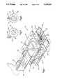
- FIG. 1is a perspective view of a sequential imaging apparatus in accordance with the present invention, showing a knee joint in position to be imaged;
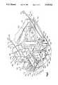
- FIG. 2is an exploded perspective view of the imaging apparatus of FIG. 1;
- FIG. 3is a top plan view with parts removed of the imaging apparatus of FIG. 1 in a locked condition
- FIG. 4is a fragmentary sectional view with parts removed showing portions of the imaging apparatus in a locked condition
- FIG. 5is a view similar to FIG. 4, showing the imaging apparatus in an unlocked condition
- FIG. 6is a view similar to FIG. 3 showing the imaging apparatus in an unlocked condition
- FIG. 7is a fragmentary sectional view with parts removed showing the relative positions of the plunger and cocking pin when the apparatus is in the locked condition;
- FIG. 8is a view similar to FIG. 7 showing the relative positions of the plunger and cocking pin when the apparatus is in the unlocked position;
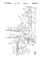
- FIG. 9is a perspective view of an imaging apparatus and index assembly in accordance with a second embodiment of the invention.
- FIG. 10is a side elevational view of the apparatus of FIG. 9 showing the index assembly in first and second index positions;
- FIG. 11is a sectional view taken along line 11--11 of FIG. 10 with parts removed, showing the index assembly in a first index position;
- FIG. 11Ais a view similar to FIG. 11 showing the index assembly in a second index position
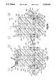
- FIG. 12is an enlarged fragmentary sectional view of a coil support portion of the apparatus of FIG. 9.
- FIG. 13is an enlarged fragmentary sectional view of a cuff and leg plate portion of the apparatus of FIG. 9.
- FIG. 14is a perspective view of a magnetic resonance imaging apparatus in accordance with the present invention.
- FIG. 1illustrates an index assembly 10 for indexing movement of a knee joint in a direction parallel to the plane of an imaging table and about an axis normal to the plane of the imaging table.
- FIG. 14schematically illustrates a known patient support table 16 for supporting a patient during imaging inside a known primary coil 14 of a known magnetic resonance imaging unit 12.
- the table 16is supported for sliding longitudinal movement into an out of the primary coil 14 in a known manner.
- the index assembly 10is positionable on the table for sliding longitudinal movement into and out of the primary coil 14.
- the index assembly 10includes a generally planar base 20 having an upper major side surface 22 (FIG. 2).
- An opening 24extends downwardly into the base 20 from the upper major side surface 22 of the base.
- risers 26are fixed to the base 20 and project upwardly from the uppermajor side surface 22 of the base.
- the risers 26support a generally planarupper panel 30 at a location spaced from and parallel to the base 20.
- Four screws 32extend through openings 34 in the upper panel 30 and into the risers 26, to secure the upper panel 30 to the base 20.
- An opening 36extends through the upper panel 30. The opening 36 is coaxial with the opening 24 in the base 20.
- a central support shaft 40has its lower end received in the opening 24 of the base 20 and its upper end extending through the opening 36 in the upper panel 30.
- the central support shaft 40is rotatable relative to the base 20 and to the upper panel 30 about an axis 42 (FIGS. 4 and 5).
- a tray 50(FIG. 2) is fixed, in any suitable manner, to the upper end of the central support shaft 40.
- the tray 50is rotatable with the central support shaft 40, relative to the base 22 and the upper panel 30.
- the tray50has a horizontal tray portion 52 and a vertical tray portion 54 fixed toeach other.
- the horizontal tray portion 52has an upper major side surface 56.
- Two leg straps 58 and 60are fixed to the tray 50.
- index disk 70is fixed for rotation with the central support shaft 40.
- the index disk 70is cylindrical in shape and has a flat upper major side surface 72 and a cylindrical outer side surface 74.
- a plurality of trip pins 76are disposed in a circular pattern on the indexdisk 70 about the axis 42.
- the trip pins 76extend upwardly from the upper major side surface 72 of the index disk 70.
- the radial distance from the axis 42 to each trip pin 76is the same.
- All of the trip pins 76are of the same dimensions and configuration.
- the radially outermost surfaces of the trip pins 76describe a circular path 78 indicated in dashed lines in FIGS. 3 and 6.
- the trip pins 76are spaced about the axis 42 in equal angular increments. In the illustrated embodiment, twenty-four trip pins 76 are provided, withan angular spacing of 15° between each trip pin. However, a different number of trip pins 76 can be provided, with correspondingly different spacing therebetween, as described below in greater detail.
- a plurality of index openings 80 in the index disk 70extend radially inwardly from the cylindrical outer side surface 74 of the index disk for a relatively short distance toward the axis 42.
- the angular spacing between the index openings 80is the same as the angular spacing between the trip pins76.
- twenty-four index openings 80are provided, each spaced 15° apart from the next, around the outer circumference of the index disk 70.
- the index openings 80are staggered relative to the trip pins 76.
- the index openings 80are spaced circumferentially equidistant between pairs of adjacent trip pins 76.
- a support block 90is fixed to the base 20 at a location spaced from the index disk 70.
- An end portion 92 (FIG. 2) of the upper panel 30projects over the support block 90.
- a cylindrical plunger opening 94(FIG. 4) extends through the support block 90 in a direction to intersect the axis 42.
- the support block 90has a reduced diameter neck portion 96 at the outer end of the plunger opening 94.
- a plunger 100is slidably received in the plunger opening 94 in the supportblock 90.
- the plunger 100has a cylindrical outer surface 102 (FIGS. 7 and 8).
- the plunger 100has a head end portion 104 (FIG. 4) and a trailing endportion 106.
- An annular groove 108 in the plunger 100is disposed between the head end portion 104 and the trailing end portion 106.
- An elongate member 110(FIG. 3) is connected to the trailing end portion 106 of the plunger 100.
- the elongate member 110(preferably a cord or a string) extends longitudinally through a compression spring 112 (FIGS. 3 and 4) disposed between the trailing end portion 106 of the plunger 100 (FIG. 4) and the support block neck portion 96.
- the spring 112biases the plunger 100 relative to the support block 90 in a direction to the left asviewed in FIGS. 3-6, toward the index disk 70.
- a swivel pin 120is fixed to and extends upwardly from the support block 90.
- the swivel pin 120(FIG. 4) is received in an opening 124 in a trigger122.
- the swivel pin 120supports the trigger 122 for pivotal movement aboutthe swivel pin relative to the base 20.
- the trigger 122has a head end portion 126 which extends over the index disk 70.
- the head end portion 126 of the trigger 122extends over the index disk 70 to a location radially inwardly of the path 78 defined by the radially outermost surfaces of the trip pins 76.
- the head end portion 126 of the trigger 122is engageableby the trip pins 76.
- a trailing end portion 128 of the trigger 122extends between opposed trigger biasing assemblies 130 and 132.
- the trigger biasing assembly 132(FIGS. 3 and 6) includes a housing 134 (FIGS. 4 and 5) fixed to the support block 90.
- a biasing block 138(FIG. 3) is received in a cylindrical opening in the housing 134.
- a compression spring 136biases the biasing block 138 against the trailing end portion 128 of the trigger 122, in a direction toward the bottom of FIGS. 3 and 6.
- the biasing assembly 130includes a compression spring 142 which urges a biasing block 144 in the opposite direction against the trailing end portion 128 of the trigger 122, that is, toward the top of FIGS. 3 and 6.
- the biasing effects placed on the trigger 122 by the biasing assemblies 130 and 132, respectively,are equal, so that the trigger 122 normally maintains the position illustrated in FIG. 6 aligned with the axis 42 and with the plunger 100.
- the trigger 122includes a cocking pin 150.
- the cocking pin 150extends downwardly from the trailing end portion 128 of the trigger.
- the cocking pin 150extends downwardly far enough so that as the trigger 122 pivots about the swivel pin 120, the cocking pin 150 can engage the outer side surface 102 of the plunger 100, as seen in FIG. 7.
- the lower end 152 of the cocking pin 150can enter the groove 108 in the plunger 100, as seen in FIG. 8.
- the index assembly 10is adapted for imaging of the knee joint of a patientlying on a table inside a primary imaging coil of a magnetic resonance imaging apparatus.
- the patientsupinates the foot and leg so that the lower leg fits along the upper major side surface 56 of the horizontal tray portion 52 of the tray 50, as illustrated in FIG. 1.
- the straps 58 and 60are placed around the lower leg to stabilize the limb and secure the lower leg to the tray 50.
- the index assembly 10is initially in a locked condition as illustrated in FIGS. 3 and 4.
- One index opening 160 of the index openings 80is aligned with the plunger 100.
- the spring 112biases the head end 104 of the plunger 100 into the index opening 160.
- the plunger 100blocks rotation ofthe index disk 70 about the axis 42. Because the index disk 70 cannot rotate, the central support shaft 42 and the tray 50 also cannot rotate. Thus, the patient's lower limb, which is strapped to the tray 50, is stabilized and a clear image of the knee joint can be taken.
- the trigger 122When the index assembly 10 is in the locked condition shown in FIGS. 3 and 4, the trigger 122 is in a pivoted orientation not pointing toward the axis 142 and not parallel to the plunger 100.
- the cocking pin 150 of the trigger 122extends below the top of the plunger 100.
- the cocking pin 150engages along the cylindrical outer side surface 102 of the plunger 100, as illustrated in FIG. 3 and in more detail in FIG. 7.
- the plunger 100holds the cocking pin 150 and the trigger 122 in this pivoted position illustrated in FIG. 3, against the biasing effect of the spring 136.
- the index assembly 10When it is desired to index the knee joint in a different orientation, the index assembly 10 must be released to allow the index disk 70 to move to the next index position.
- the patientpulls a handle 164 attached to the elongate member 110 extending from the plunger 100.
- the plunger 100is retracted against the bias of the spring 112, from the blocking position illustrated in FIGS. 3 and 4 to the position illustrated in FIGS. 5 and 6.
- the head end portion 104 of the plunger 100is retracted out of the index opening 160.
- the index disk 70is then free to rotate if the patient movesthe joint.
- the groove 108 in the plungermoves into a position adjacent the cocking pin 150.
- the cocking pin 150is then free to move laterally into the groove 108 in the plunger 100.
- the biasing effect of the spring 136pivots the trigger 122 so that the cocking pin 150 moves into the groove 108 of the plunger 100, centeredover the plunger.
- the trigger 122is in a cocked position.
- the springs 136 and 142hold the trigger 122 centered between them, and the index assembly10 is then in the position shown in FIGS. 5, 6, and 8.
- the engagement of the cocking pin 150 in the groove 108 of the plunger 100blocks movement of the plunger 100 in a direction toward the index disk 70.
- the patientcan release the handle 164, and the plunger 100 will not move into engagement with the index disk 70 or into any of the index openings 80.
- the patientcan then move the knee joint toward the next sequential index position at which an image is to be taken.
- the limb portion strapped to the tray 50moves thetray 50 and causes the index disk to rotate, for example, in the direction indicated by the arrow 166 in FIG. 3.
- the trip pin closest to the trigger 122which is the trip pin designated 168 in FIG. 3, engages the head end portion 126 of the trigger 122.
- the trip pin 168pivots the trigger 122 about the swivel pin 120, from the cocked position illustrated in FIGS. 5 and 6 back toward the uncocked position illustrated in FIGS. 3 and 4.
- the cocking pin 150moves out of the groove 108 in the plunger 100, from the position illustrated in FIG. 8 to the position illustrated in FIG. 7.
- the plungeris then free to move longitudinally in the plunger opening 94 in the support block 90.
- the biasing effect of the plunger spring 112causes the plunger 100 to move toward the index disk 70.
- the head end portion 104 of the plunger 100engages the cylindrical outer side surface 74 of the index disk 70.
- the next sequential index opening 162moves into position between theaxis 42 and the plunger 100, and the head end portion 104 of the plunger moves into the index opening 162, blocking further rotation of the index disk 70.
- the construction ofthe index assembly 10assures that whenever the patient releases the index assembly 10 by pulling on the handle 164, and then moves his knee joint, the index assembly 10 will lock in a next index position a given number ofdegrees from the previous index position. In the illustrated embodiment, that number of degrees is 15°. That number of degrees can be changed by placing the index openings 80 and the trip pins 76 at differentangular spacings around the index disk 70.
- the movement of the index diskwill be automatically limited to 5° of indexing each time.
- the plunger100will always engage in the next sequential index opening 80 in the indexdisk 70. This assures that a precise repeatable sequence of images can be taken using the index assembly 10.
- the index assembly 10is used in a magnetic resonance imaging application. Therefore, all of the parts of the index assembly 10 are made of nonferromagnetic materials. Preferably, the majority of the parts of the index assembly 10 are made of polyethylene orof Delrin® brand plastic.
- the plunger spring 112 and the trigger biasing springs 136 and 142can be made of beryllium copper or of a similar nonferromagnetic material having the desired spring characteristics.
- the straps 58 and 60 for stabilizing the patient's leg tothe tray 50can be made of nylon with suitable fasteners such as Velcro® brand fasteners.
- the elongate member 110can be a simple string or cord made of fabric or plastic.
- the present inventionis not limited to imaging of a knee joint, and that the present invention is not limited to imaging in a magnetic resonance imaging apparatus.
- the principles of the illustrated indexing assemblyare applicable to imaging of almost any joint.
- the indexing assembly 10can be configured to support other joints such as an elbow joint, an ankle joint, a wrist joint, or a shoulder joint. Sequential imaging of all these joints can be useful.
- An indexing assembly in accordance with the present inventioncan also be used in conjunction with a CAT scanner, an X-ray imaging apparatus, or other types of imaging apparatus.
- the present inventionprovides an index assembly 10 for imaging a joint of a patient movable into a plurality of different orientations.
- the index assembly 10includes an index disk 70 connected for movement with the joint by the tray 50.
- the index assembly 10has a plurality of sequential index positions, two of which are illustrated in FIGS. 3 and 6.
- a plunger 110is movable relative to the index disk 70 between a first position (illustrated in FIG. 3) blocking movement of the index disk out of any one of the sequential index positions, and a second position (illustrated in FIG. 6) not blocking movement of the index disk out of any one of the sequential index positions.
- An actuator 110, 164is connected to the plunger 100 for moving the plunger between the first position and the second position.
- the index assemblyincludes trip pins 76and a trigger 122 for limiting movement of the index disk 70 to movement into the next one of the sequential index positions upon movement of the index disk out of any one of the sequential index positions.
- the present inventioncontemplates that the entire index assembly 10 is disposed inside a primary imaging coil of a magnetic resonance imaging apparatus or the like in a location closely adjacent to a joint during imaging of the joint.
- the only parts remote from and not closely adjacent to the joint during imaging of the joint arearelease control member or handle 164 and an elongate connecting member 110 connecting the release control member with the plunger 100. These parts are also within the primary imaging coil as they are grasped by the patient's hand.
- the present inventionprovides an actuator 164,110 operable by a patient and connected to the plunger 100 for moving the plunger 100 into a position to allow movement of the index disk 70 out of a sequential index position, subsequent to imaging of a joint.
- the index assemblyfurther includes a tray 50 and a central support shaft 40 for transmitting the force of movement of the joint between different orientations to the index disk 70 to move the index disk into the next oneof its sequential index positions upon movement of the joint into a different orientation.
- Limiting means including the trigger 122is operable to move the plunger 100 back into its locking position in one of the index openings 80, to allow imaging of the joint in the next one of its different orientations.
- an indexing assemblyfor movement of the knee joint about an axis parallel to the plane of an imaging table and in a direction transverse to the plane of the table.
- Thepatientlies on his back inside a primary imaging coil of a magnetic resonance imaging apparatus, and moves his lower leg up and down to extendand flex the knee joint.
- the kneeis elevated so that the knee joint can bemoved through its full range of motion.
- FIGS. 9-13An index assembly 200 in accordance with the second embodiment of the invention is illustrated in FIGS. 9-13.
- FIGS. 9 and 10show portions of animaging table 202 which is slidable inside a primary coil (not shown) of a magnetic resonance imaging apparatus.
- the table 202has an upper major side surface 203.
- the patientlies on a pad 204 on the table 202.
- the patient's headis towards the right as viewed in FIGS. 9 and 10.
- the table202, with the pad 204,is movable longitudinally in and out of the primary coil.
- the table 202is slid out to set up and place the patient on the table, then is slid in for imaging.
- the secondary coil assembly 206includes a frame 208 with a lower frame portion 210 and two upright frame portions 212 and 214.
- the secondary coilitself includes a lower coil portion 216 fixed to the coil frame 208.
- An upper coil portion 218is pivotally mounted at one end 220 to the frame 208.
- the upper coil portion 218is pivotable from the closed position shown in FIGS. 9 and 10 to an open position (not shown) to allow the patient's leg to be placed inside the secondary coil from above.
- the upper coil portion 218then is swung back to the closed position to image the knee joint.
- the coil lower frame portion 216(FIG. 12) has on its lower surface a rib 222 which extends parallel to the length of the table 202.
- the rib 222normally fits in a complementary groove 224 on the table 202, so that the secondary coil assembly 206 is slidable along the table 202 to image at various locations along the table.
- the kneeis raised up off the table 202 to allow imaging of the knee joint through its range of motion.
- the secondary coil assembly 206must also be raised up off the table 202.
- a pair of coil support blocks 226 and 228support the secondary coil assembly 206 in its raised position.
- Each coil support blockhas on its lower surface a rib 230 which fits into the groove 224 on the table 202.
- Each coil support block 226, 228also has on its upper surface a groove 232 which accepts the rib 222 of the coil lower frame portion 216.
- the coil support blocks 226 and 28 and the secondary coil assembly 206areslidable along the table 202 to image at various locations along the table.
- Each coil support block 226, 228has a fastener opening 234 for receiving therethrough a suitable fastener (not shown) to secure the coil support block to an existing opening 236 in the table 202.
- Each coil support block226, 228also has an actuator passage 238 extending longitudinally through the coil support block in a direction parallel to the length of the table 202, for a purpose to be described below.
- a coil clip 240attaches the secondary coil assembly 206 to the coil support block 226.
- a pair of thumb screws 242fix the coil clip 240 to thecoil support block 226.
- a similar coil clip 246holds the other end of the coil assembly 206 to the other coil support block 228.
- a leg support wedge 250raises the patient's knee so that it fits within the raised secondary coil assembly 206.
- the leg support wedge 250includes a lower wedge member 252, an upper wedge member 254, and two wedge uprights256 and 258.
- the lower wedge member 252is disposed on the table 202.
- the wedge uprights 256 and 258support the upper wedge member 254, at an angle, raised up from the lower wedge member 252.
- the leg support wedge 250raises thepatient's knee so that it fits within the secondary coil assembly 206.
- the index assembly 200includes a U-shaped index holder 260 (FIGS. 9-11).
- the index holder 260has a lower portion 262.
- a left support arm 264 and aright support arm 266extend upwardly from the index holder lower portion 262.
- Two fasteners 268extend through the index holder lower portion 262 and secure the index holder 260 to an end surface 269 of the table 202, asshown in FIGS. 9 and 10.
- a pivot pin 270(FIGS. 9 and 10) having an axis of rotation 272 extends between the left and right support arms 264 and 266.
- the axis 272extends parallel to the plane of the table 202 and in a direction across the widthof the table.
- the pivot pin 270supports an index disk 280 for pivotal movement relative to the index holder 260.
- the index disk 280is disposed between the left and right support arms 264 and 266 of the index holder.
- the index disk 280is a part circular structure, shaped somewhat like a piece of pie, having a flat upper end surface 282 and a flat lower end surface 284.
- An outer circumferential surface 286extends between the upper and lower end surfaces.
- a flat left outer side surface 290 and a flat right outer side surface 292are on opposite sides of the index disk 280.
- the first or left set of index openings 294extend inwardly into the index disk 280 from the left outer side surface 290 of the index disk.
- Theindex openings 294are arrayed in a part circular pattern on the index disk280 with the axis 272 as the center of the pattern.
- the index openings 294are all equally spaced from the axis 272.
- the index openings 294are spaced from each other in equal angular increments about the axis 272 and near the outer edge 286 of the index disk 280. In the illustrated embodiment, the index openings 294 are 20' apart from each other, althoughthis spacing could be different as described in more detail below.
- the second or right set of index openings 296extend inwardly into the index disk 280 from the right outer side surface of the index disk.
- the index openings 296are arrayed in a part circular pattern on the index disk 280 with the axis 272 as the center of the pattern.
- the index openings 296are all equally spaced from the axis 272.
- the index openings 296are spaced from each other in equal angular increments about the axis 272 and near the outer axis of the index disk 280. In the illustrated embodiment, the index openings 296 are 20° apart from each other, although this spacing could be different as described in more detail below.
- the index openings 294are staggered from the index openings 296. That is, the index openings 294 on one side of the disk 280 do not align with the index openings 296 on the opposite side of the disk. Instead, the index openings 294 are disposed so as to fall halfway between pairs of index openings 296 of the other set. Thus, there is a 10° angular increment between an index opening 294 of one set and an adjacent index opening 296 of the other set.
- a leg plate 300is fixed to the index disk 280 for movement with the index disk.
- Three leg plate attachment screws 302extend through the leg plate 300 and through the upper end surface 282 of the index disk 280, to securethe leg plate to the index disk.
- the leg plate 300is long enough to substantially support the lower leg of the patient.
- a left slider groove 304(FIGS. 11, 13) is shaped to receive a tenon portion 306 of a cuff slider 308.
- a right slider groove 310extends parallel to the left slider groove 304, also for the length of the leg plate 300.
- the right slider groove 310is similarly shaped to receive the tenon portion 306 of the cuff slider 308.
- the cuff slider 308is slidable in one or the other of the slider grooves 304 and 306.
- a leg cuff 312is fixed to the slider 308 for movement with the slider.
- a plurality of cuff attachment screws 314extend through the cuff 312 into the slider 308 to secure the cuff to the slider.
- the cuff 312is slidable with the slider 308 on the index disk 280.
- the index diskpivots about the axis 272
- the cuffis free to slide along the upper end surface 282 of the index disk.
- Two leg straps 315(FIG. 9) are attached tothe leg cuff 312. The straps 315 are wrapped around the lower leg of the patient to secure the lower leg to the cuff 312.
- the index assembly 200includes a left plunger assembly 312 and a right plunger assembly 318, for controlling the pivotal location of the index disk 280.
- the left plunger assembly 316(FIG. 11) includes a left plunger support block 320 fixed to the index holder left support arm 264 by two screw fasteners 322.
- a left plunger 324extends through a passage 326 in the left plunger support block 320.
- the left plunger 324has a trailing end portion 328 to which is connected a left plunger actuator 330.
- the left plunger actuator 330is a cord or string 332 having a handle or finger grip 334 on its end remote from the left plunger 324.
- the actuator cord 332extends from the left plunger 324 through the actuator passage 238 (FIG. 9) in the left coil support block 228, to a location where it can begrasped by the patient's left hand.
- the left plunger 324projects from the left plunger support block 320 into the index holder left support arm 264.
- a body portion 336 of the left plunger 324is received in a chamber 338 in the index holder left support arm 264.
- a compression spring 340is disposed in the chamber 338 between the left plunger support arm 264 and the body portion 336 of the left plunger 324.
- the compression spring 340biases the left plunger 324 towardthe index disk 280, in a direction to the right as viewed in FIG. 9.
- a pulling force applied by the patient, through the actuator 330is sufficient to overcome the biasing effect of the spring 340 and retract the left plunger 324 away from the index disk 280, in a direction to the left as viewed in FIG. 9.
- a leading end portion 342 of the left plunger 324extends from the left plunger body portion 336 toward the index disk 280.
- the leading end portion 342is aligned with the track of the left index openings 294 in the index disk 280.
- the left index openings 294sequentially come into position adjacent the left plunger 324 so that the leading end portion 342 of the left plunger can enter into a selected one of the left index openings to block pivotal movement of the index disk.
- the leading end portion 342 of the left plunger 324When the leading end portion 342 of the left plunger 324 is not engaged in one of the left index openings 294 in the index disk 280, the leading end portion of the left plunger rides along the left outer side surface 290 of the index disk, between the left index openings.
- the right plunger assembly 318(FIG. 11A) is similar to the left plunger assembly.
- the right plunger assembly 318includes a right plunger support block 350 fixed to the index holder right support arm 266 by two screw fasteners 352.
- a right plunger 354extends through a passage 356 in the right plunger support block 350.
- the right plunger 354has a trailing end portion 358 to which is connected a right plunger actuator 360.
- the right plunger actuator 360is a cord or string 362 having a handle or finger grip 364 on its end remote from the right plunger 354.
- the actuator cord 362extends from the right plunger 354 through an actuator opening 335 (FIG. 9) in the right coil support block 228, to a location where it can be grasped by the patient's right hand.
- the right plunger 354projects from the right plunger support block 350 into the index holder right support arm 266.
- a body portion 366 of the right plunger 354is received in a chamber 368 in the index holder right support arm 266.
- a compression spring 370is disposed in the chamber368 between the right plunger support arm 266 and the body portion 366 of the right plunger 354.
- the compression spring 370biases the right plunger354 toward the index disk 280, in a direction to the left as viewed in FIG.11A.
- a pulling force applied by the patient, through the actuator 360is sufficient to overcome the biasing effect of the spring 370 and retract the right plunger 354 away from the index disk 280, in a direction to the right as viewed in FIG. 9.
- a leading end portion 372 of the right plunger 354extends from the right plunger body portion 366 toward the index disk 280.
- the leading end portion 372is aligned with the track of the right index openings 296 in the index disk 280.
- the right index openings 296sequentially come into position adjacent the right plunger 354 so that the leading end portion 372 of the right plunger354 can enter into a selected one of the right index openings to block pivotal movement of the index disk.
- the leading end portion 372 of the right plunger 354is not engaged in one of the right index openings 296 in the index disk 280, the leading end portion of the right plunger rides along the right outer side surface 292 of the index disk, between the openings.
- the index assembly 200 in the illustrated embodimentis constructed for usein magnetic resonance imaging of a knee joint of a patient lying on his back inside a primary imaging coil of a magnetic resonance imaging apparatus.
- the imaging table 202is first slid out of the primary coil so the patient can lie down on the table.
- the secondary coil assembly 206is opened, by swinging the upper coil portion 218 away from the lower coil portion 216.
- the patientlies on the table 202 and rests his upper leg on the leg support wedge 250.
- the lower legrests on the cuff 312.
- the patient's knee jointis disposed above the lower portion 216 of the secondary coil.
- the upper coil portion 218is then repositioned over the lower coil portion 216 for imaging of the knee joint.
- the straps 315are fitted around the lower leg to stabilize the joint and secure the lower leg to the cuff 312.
- the table 202is then slid into the primary imaging coil.
- the index assembly 200can be in any desired index position to start.
- the index assembly 200can be in the index position shown in solid lines in FIG. 10, in which the leg plate 300 and the cuff 312 extendparallel to the plane of the table 202.
- the various elements of the index assembly 200are in the positions shown in solid lines in FIG. 8 and in FIG. 9.
- the cuff 312 and the slider 308are disposed at a relatively distal location (to the left as viewed in FIG. 10) along the leg plate 300.
- the leading end portion 342 of the left plunger 324is engaged in a left index opening380 (FIG. 11) which is one of the plurality of left index openings 294 in the index disk 280.
- the right plunger 354is not engaged in any of the plurality of right index openings 296 in the index disk 280--instead, the leading end portion 372 of the right plunger is in abutting engagement with the right outer side surface 292 of the index disk.
- the engagement ofthe left plunger 324 in the index disk 280blocks pivotal movement of the index disk about the pivot pin 270.
- the cuff 312 and the lower legare fixed in position, and a clear image of the knee joint can be taken.
- the patientgrasps the left actuator handle 334 and pulls on it.
- the force of the patient's pullingis transmitted through the actuator cord 332 to the leftplunger 324.
- the left plunger 324is retracted against the biasing effect of the left plunger spring 340.
- the leading end portion 342 of the left plunger 324comes out of the index opening 380 in the index disk 280.
- the left plunger 324no longer blocks pivotal movement of the index disk 280, and the index disk can move out of the first index position shown in solid lines in FIG. 11. Since the right plunger 354 is not engaged in any of the plurality of right index openings 296 in the index disk 280, the index disk is free to pivot about the axis 272. The weight of the patient's lower leg, pressing down through the cuff 312, theslider 308, and the leg plate 300, causes the index disk 280 to pivot downward in the direction indicated by the arrow 382 in FIG. 10. As the index disk 280 pivots, the leading end portion 372 of the right plunger 354 slides along the right outer side surface 292 of the index disk. The biasing effect of the right plunger spring 370 forces the leading end portion 372 of the right plunger 354 against the outer side surface 292 ofthe index disk 280.
- the index opening 384(FIG. 11A), which is one of the plurality of right indexopenings 296 in the index disk, becomes aligned with the right plunger 354.
- the leading end portion 372 of the right plunger 354moves into the index opening 384.
- the engagement of the right plunger 354 in the index disk 280blocks pivotal movement of the index disk 280 about the axis 272.
- the cuff 312 and the lower legare fixed in a second index position, and a clear image of the knee joint can be taken in this second index position, in which the knee joint is moved 10° from the firstindex position.
- the index assembly 200is constructed so that, upon patient release of one of the plunges 324 and 354 via its actuator, the index disk 280 will automatically move into the next sequential index position, without skipping any intervening index positions. This ensures accurate and repeatable imaging sequences. If desired, of course, the patient can actuate the index assembly 200 as many times as directed between images, for example to take images at every 20° through therange of motion of the joint rather than every 10°. Imaging at otherangular increments can be provided by placing the index openings 294 and 296 in the index disk 280 at different angular spacings, such as 5°rather than 10°, etc.
- the knee jointAs the knee joint is flexed (moved from a straighter position to a more bent position), the knee itself tends to rise, thus pulling the lower leg closer toward the secondary coil assembly 206.
- the sliding movement of thecuff 312 on the index disk 280accommodates this.
- the cuff 312As seen in FIG. 10, the cuff 312 is in a more distal position along the index disk 280 when the upper end surface 282 of the index disk is parallel to the plane of the table 202.
- the cuff 312 and the slider 308slide proximally (to the right as viewed in FIG. 10) along the index disk 280.
- the knee jointis not strained but instead is allowed to retain its normal configuration.
- FIG. 10illustrates movement of the index disk 280 through an angle of 30° between the position shown in solid lines and the position shown in phantom. This is for purposes of clarity in the drawings. Showingthe index disk 280 moved only through a 10° increment, for example, in FIG. 10, would not show the pivotal movement so clearly. Thus, the 30° range of motion shown in FIG. 10 between the first index position shown in solid lines and the second index position shown in phantom would be achieved by indexing three times--left, right, and left.
- the index holder 260is secured to the end surface 269 of the table 202. This allows the patient's foot to drop down below the uppermajor side surface 203 of the table 202, when the index assembly 200 is moved to a low position (past that shown in phantom in FIG. 10). Thus, theknee joint can be moved through a greater range of motion than if the foot could not drop below the upper major side surface 203 of the table 202. Accordingly, the physician can image the knee joint through a greater range of motion.
- This mounting of the index assembly on the end of the tableprovides substantial advantages as compared to prior art imaging in which the patient's entire body remains above the top of the imaging table.
- a typical imaging tableis about 6" deep (tall).
- the tabletakesup 6" of vertical space inside the primary coil, space which can then not be used for imaging.
- Mounting the index assembly on the end of the table in accordance with the present inventionregains this 6" of space, and allows much greater range of imaging motion.
- the tableworks for the patient and physician, rather than against them.
- the knee jointcan be imaged through a range of about 60° with the indexing assembly 200, while the prior art images only allow imaging through a range of about 30°.
- the imaging apparatus in accordance with both the first embodiment (FIGS. 1-8) and second embodiment (FIGS. 9-13)allow the patient to lie on his back inside the primary coil.
- Prior art imaging apparatus for indexingrequire the patient to lie on his stomach. Since it takes two to five minutes for each image (cut), the patient can be required to lie on his stomach inside a claustrophobic primary coil for30 to 60 minutes to image a joint with prior art imaging apparatus. This isextremely uncomfortable. The patient's comfort is vastly increased by lyingon his back, and the imaging process is consequently improved.
- the known secondary coil assembly 206is offset laterally from the longitudinal center line of the table 202 so that the coil portions 216 and 218 are not over the center line of the table 202 but rather are offset slightly to one side.
- the secondary coilcan be flipped 180°to place the coil portions 216 and 218 offset slightly to the other side ofthe center of the table 202.
- clear images of the kneecan be taken with the secondary coil with either the left or right knee joint in its normal position off the centerline of the body.
- the leg plate 300has both the left slider groove 304 and the right slider groove 310. When the slider 308 is placed in the left slider groove 304, the cuff 312 is in the proper position to image the left knee. When the slider 308 is placed in the right slider groove 310, the cuff 312 is then in the proper position to image the rightknee.
- the coil support blocks 226 and 228in thesecond embodiment of the invention raise the secondary coil assembly 206 off its normal position on the table 202. It may be necessary or desirableto set the secondary coil assembly 206 at different heights relative to thetable 202. If so, coil support blocks can be provided with different heights to enable setting of the secondary coil assembly 206 at different heights. Also, the leg support wedge 250 can be replaced with similar wedges having different angles and heights, to raise the knee to differentheights above the table 202.
Landscapes
- Health & Medical Sciences (AREA)
- Life Sciences & Earth Sciences (AREA)
- Engineering & Computer Science (AREA)
- Medical Informatics (AREA)
- General Health & Medical Sciences (AREA)
- Animal Behavior & Ethology (AREA)
- Public Health (AREA)
- Veterinary Medicine (AREA)
- Physics & Mathematics (AREA)
- Biomedical Technology (AREA)
- Nuclear Medicine, Radiotherapy & Molecular Imaging (AREA)
- Radiology & Medical Imaging (AREA)
- Biophysics (AREA)
- Pathology (AREA)
- Heart & Thoracic Surgery (AREA)
- High Energy & Nuclear Physics (AREA)
- Molecular Biology (AREA)
- Surgery (AREA)
- Optics & Photonics (AREA)
- Magnetic Resonance Imaging Apparatus (AREA)
Abstract
Description
Claims (32)
Priority Applications (3)
| Application Number | Priority Date | Filing Date | Title |
|---|---|---|---|
| US07/927,341US5329924A (en) | 1991-12-04 | 1992-08-10 | Sequential imaging apparatus |
| US08/223,468US5562094A (en) | 1991-12-04 | 1994-04-05 | Sequential imaging apparatus |
| US09/394,575US6141579A (en) | 1991-12-04 | 1999-09-10 | Sequential imaging apparatus |
Applications Claiming Priority (2)
| Application Number | Priority Date | Filing Date | Title |
|---|---|---|---|
| US07/802,358US5349956A (en) | 1991-12-04 | 1991-12-04 | Apparatus and method for use in medical imaging |
| US07/927,341US5329924A (en) | 1991-12-04 | 1992-08-10 | Sequential imaging apparatus |
Related Parent Applications (1)
| Application Number | Title | Priority Date | Filing Date |
|---|---|---|---|
| US07/802,358Continuation-In-PartUS5349956A (en) | 1991-12-04 | 1991-12-04 | Apparatus and method for use in medical imaging |
Related Child Applications (1)
| Application Number | Title | Priority Date | Filing Date |
|---|---|---|---|
| US08/223,468DivisionUS5562094A (en) | 1991-12-04 | 1994-04-05 | Sequential imaging apparatus |
Publications (1)
| Publication Number | Publication Date |
|---|---|
| US5329924Atrue US5329924A (en) | 1994-07-19 |
Family
ID=46246762
Family Applications (2)
| Application Number | Title | Priority Date | Filing Date |
|---|---|---|---|
| US07/927,341Expired - LifetimeUS5329924A (en) | 1991-12-04 | 1992-08-10 | Sequential imaging apparatus |
| US08/223,468Expired - LifetimeUS5562094A (en) | 1991-12-04 | 1994-04-05 | Sequential imaging apparatus |
Family Applications After (1)
| Application Number | Title | Priority Date | Filing Date |
|---|---|---|---|
| US08/223,468Expired - LifetimeUS5562094A (en) | 1991-12-04 | 1994-04-05 | Sequential imaging apparatus |
Country Status (1)
| Country | Link |
|---|---|
| US (2) | US5329924A (en) |
Cited By (49)
| Publication number | Priority date | Publication date | Assignee | Title |
|---|---|---|---|---|
| US5462059A (en)* | 1994-05-25 | 1995-10-31 | The Regents Of The University Of California | Method for assessing and displaying vascular architecture using ultrasound |
| US5520181A (en)* | 1993-11-24 | 1996-05-28 | Technology Funding Secured Investors Ii | Positioning device for producing movement in the shoulder |
| US5542423A (en)* | 1991-12-04 | 1996-08-06 | Apogee Medical Products, Inc. | Indexing assembly for joint imaging |
| US5562094A (en)* | 1991-12-04 | 1996-10-08 | Apogee Medical Products, Inc. | Sequential imaging apparatus |
| US5697164A (en)* | 1994-11-18 | 1997-12-16 | Siemens Aktiengesellschaft | Movable positioning aid permitting abduction and rotation of the shoulder joint for a kinematic imaging examination thereof |
| US5758647A (en)* | 1996-10-17 | 1998-06-02 | Cummins; Jimmie E. | Support and indexing apparatus for lumbar region imaging |
| US5810006A (en)* | 1993-04-06 | 1998-09-22 | Fonar Corporation | Multipositional MRI for kinematic studies of movable joints |
| US5810729A (en)* | 1997-12-30 | 1998-09-22 | General Electric Company Medical Systems | Method for measuring and adding limb angle indicia to MR images |
| USD407820S (en) | 1997-09-29 | 1999-04-06 | Ge Yokogawa Medical Systems, Limited | Wrist holder for MRI apparatus |
| US5931781A (en)* | 1996-12-18 | 1999-08-03 | U.S. Philips Corporation | MR method for the imaging of jointed movable parts |
| EP0995397A3 (en)* | 1998-10-05 | 2000-05-03 | Esaote S.p.A. | Diagnostic and/or therapeutic treatment apparatus, particularly for nuclear magnetic resonance imaging |
| US20040133097A1 (en)* | 1991-12-04 | 2004-07-08 | Bonutti Peter M. | Apparatus and method for use in medical imaging |
| US20050049491A1 (en)* | 1998-10-05 | 2005-03-03 | Esaote S.P.A. | Nuclear magnetic resonance imaging device |
| US20080086072A1 (en)* | 2006-10-04 | 2008-04-10 | Bonutti Peter M | Methods and devices for controlling biologic microenvironments |
| US20080204019A1 (en)* | 2007-02-28 | 2008-08-28 | Ting Qiang Xue | High field magnetic resonance imaging apparatus and method for obtaining high signal-to-noise by its receiving coil |
| WO2008116203A2 (en) | 2007-03-22 | 2008-09-25 | Marctec, Llc | Methods and devices for intracorporeal bonding or interlocking of implants with thermal energy |
| WO2009029908A1 (en) | 2007-08-30 | 2009-03-05 | Marctec, Llc | Methods and devices for utilizing thermal energy to bond, stake and/or remove implants |
| US7854750B2 (en) | 2002-08-27 | 2010-12-21 | P Tech, Llc. | Apparatus and method for securing a suture |
| US7881768B2 (en) | 1998-09-14 | 2011-02-01 | The Board Of Trustees Of The Leland Stanford Junior University | Assessing the condition of a joint and devising treatment |
| US20110030698A1 (en)* | 2009-08-06 | 2011-02-10 | Kaufman Kenton R | Mri compatible knee positioning device |
| US20110139761A1 (en)* | 2009-12-15 | 2011-06-16 | Kabushiki Kaisha Kobe Seiko Sho (Kobe Steel, Ltd.) | Flux-cored wire for stainless steel arc welding |
| US7967820B2 (en) | 2006-02-07 | 2011-06-28 | P Tech, Llc. | Methods and devices for trauma welding |
| US8036729B2 (en)* | 1998-09-14 | 2011-10-11 | The Board Of Trustees Of The Leland Stanford Junior University | Assessing the condition of a joint and devising treatment |
| US8265730B2 (en) | 1998-09-14 | 2012-09-11 | The Board Of Trustees Of The Leland Stanford Junior University | Assessing the condition of a joint and preventing damage |
| US8496657B2 (en) | 2006-02-07 | 2013-07-30 | P Tech, Llc. | Methods for utilizing vibratory energy to weld, stake and/or remove implants |
| US8617185B2 (en) | 2007-02-13 | 2013-12-31 | P Tech, Llc. | Fixation device |
| US8747439B2 (en) | 2000-03-13 | 2014-06-10 | P Tech, Llc | Method of using ultrasonic vibration to secure body tissue with fastening element |
| US8808329B2 (en) | 1998-02-06 | 2014-08-19 | Bonutti Skeletal Innovations Llc | Apparatus and method for securing a portion of a body |
| US8814902B2 (en) | 2000-05-03 | 2014-08-26 | Bonutti Skeletal Innovations Llc | Method of securing body tissue |
| US8845687B2 (en) | 1996-08-19 | 2014-09-30 | Bonutti Skeletal Innovations Llc | Anchor for securing a suture |
| US8845699B2 (en) | 1999-08-09 | 2014-09-30 | Bonutti Skeletal Innovations Llc | Method of securing tissue |
| US8932330B2 (en) | 2000-03-13 | 2015-01-13 | P Tech, Llc | Method and device for securing body tissue |
| US9060767B2 (en) | 2003-04-30 | 2015-06-23 | P Tech, Llc | Tissue fastener and methods for using same |
| US9089323B2 (en) | 2005-02-22 | 2015-07-28 | P Tech, Llc | Device and method for securing body tissue |
| US9138222B2 (en) | 2000-03-13 | 2015-09-22 | P Tech, Llc | Method and device for securing body tissue |
| US9149281B2 (en) | 2002-03-20 | 2015-10-06 | P Tech, Llc | Robotic system for engaging a fastener with body tissue |
| US9173647B2 (en) | 2004-10-26 | 2015-11-03 | P Tech, Llc | Tissue fixation system |
| US9226828B2 (en) | 2004-10-26 | 2016-01-05 | P Tech, Llc | Devices and methods for stabilizing tissue and implants |
| US9271766B2 (en) | 2004-10-26 | 2016-03-01 | P Tech, Llc | Devices and methods for stabilizing tissue and implants |
| US9286686B2 (en) | 1998-09-14 | 2016-03-15 | The Board Of Trustees Of The Leland Stanford Junior University | Assessing the condition of a joint and assessing cartilage loss |
| US9439642B2 (en) | 2006-02-07 | 2016-09-13 | P Tech, Llc | Methods and devices for utilizing bondable materials |
| US9463012B2 (en) | 2004-10-26 | 2016-10-11 | P Tech, Llc | Apparatus for guiding and positioning an implant |
| US9770238B2 (en) | 2001-12-03 | 2017-09-26 | P Tech, Llc | Magnetic positioning apparatus |
| US9888916B2 (en) | 2004-03-09 | 2018-02-13 | P Tech, Llc | Method and device for securing body tissue |
| US10058393B2 (en) | 2015-10-21 | 2018-08-28 | P Tech, Llc | Systems and methods for navigation and visualization |
| US10076377B2 (en) | 2013-01-05 | 2018-09-18 | P Tech, Llc | Fixation systems and methods |
| US11246638B2 (en) | 2006-05-03 | 2022-02-15 | P Tech, Llc | Methods and devices for utilizing bondable materials |
| US11253296B2 (en) | 2006-02-07 | 2022-02-22 | P Tech, Llc | Methods and devices for intracorporeal bonding of implants with thermal energy |
| US11278331B2 (en) | 2006-02-07 | 2022-03-22 | P Tech Llc | Method and devices for intracorporeal bonding of implants with thermal energy |
Families Citing this family (12)
| Publication number | Priority date | Publication date | Assignee | Title |
|---|---|---|---|---|
| DE4329922A1 (en)* | 1993-09-04 | 1995-03-09 | Philips Patentverwaltung | MR imaging method and arrangement for carrying out the method |
| US6493571B1 (en) | 1997-04-11 | 2002-12-10 | William Beaumont Hospital | Rapid magnetic resonance imaging and magnetic resonance angiography of multiple anatomical territories |
| AT2458U1 (en)* | 1997-04-18 | 1998-11-25 | Zembsch Alexander Dr | DEVICE FOR THE DEFINED GUIDANCE OF EXTREMITIES FOR THE FUNCTIONAL DIAGNOSTICS OF MOVEMENT OF EXTREMITY JOINTS, ESPECIALLY OF KNEE JOINTS, BY MEANS OF MAGNETIC RESONANCE TOMOGRAPHY |
| USD406347S (en)* | 1997-09-29 | 1999-03-02 | Ge Yokogawa Medical Systems, Limited | Ankle holder for MRI apparatus |
| USD402370S (en) | 1997-09-29 | 1998-12-08 | Ge Yokogawa Medical Systems, Limited | Knee holder for MRI apparatus |
| USD402035S (en) | 1997-09-29 | 1998-12-01 | Ge Yokogawa Medical Systems, Limited | Knee holder for MRI apparatus |
| SE515679C2 (en)* | 1999-12-20 | 2001-09-24 | Jan A G Willen | Device for compressing the lower extremities for medical imaging purposes |
| US6754520B2 (en)* | 2001-10-19 | 2004-06-22 | Koninklijke Philips Electronics N.V. | Multimodality medical imaging system and method with patient handling assembly |
| US7254438B2 (en)* | 2001-10-19 | 2007-08-07 | Koninklijke Philips Electronics N.V. | Multimodality medical imaging system and method with intervening patient access area |
| US6961606B2 (en)* | 2001-10-19 | 2005-11-01 | Koninklijke Philips Electronics N.V. | Multimodality medical imaging system and method with separable detector devices |
| US7669602B2 (en)* | 2005-12-22 | 2010-03-02 | Mcginnis William J | Shoulder press |
| CU24138B1 (en)* | 2013-06-24 | 2015-12-23 | Ct De Ingeniería Genética Y Biotecnología | FOOT POSITIONING SYSTEM FOR MAGNETIC RESONANCE STUDIES |
Citations (22)
| Publication number | Priority date | Publication date | Assignee | Title |
|---|---|---|---|---|
| US1239146A (en)* | 1914-02-16 | 1917-09-04 | Victor Electric Corp | X-ray table. |
| US2801142A (en)* | 1954-11-29 | 1957-07-30 | Jesse R Adams | Limb support for operating tables |
| US2972505A (en)* | 1959-09-16 | 1961-02-21 | Ritter Co Inc | Arm rest for surgical tables |
| US3025397A (en)* | 1959-06-11 | 1962-03-13 | Travis | Skull radiography apparatus |
| US3124328A (en)* | 1964-03-10 | kortsch | ||
| US3521876A (en)* | 1967-12-29 | 1970-07-28 | Jeffrey P Smith | Body member support for x-ray examination |
| US3528413A (en)* | 1968-01-23 | 1970-09-15 | Marion L Aydt | Limb support |
| US3766384A (en)* | 1971-04-28 | 1973-10-16 | Tower Co Inc | Surgical table |
| US4050355A (en)* | 1976-08-16 | 1977-09-27 | Kennametal Inc. | Indexing device |
| US4232681A (en)* | 1978-05-16 | 1980-11-11 | Olaf Tulaszewski | Leg positioning device for X-ray filming |
| US4256112A (en)* | 1979-02-12 | 1981-03-17 | David Kopf Instruments | Head positioner |
| US4291229A (en)* | 1979-12-10 | 1981-09-22 | Patt Kenneth W | Support and restraining device for arthographic examination of the knees |
| US4323080A (en)* | 1980-06-23 | 1982-04-06 | Melhart Albert H | Ankle stress machine |
| US4407277A (en)* | 1980-10-27 | 1983-10-04 | Ellison Arthur E | Surgical apparatus |
| US4562588A (en)* | 1981-11-20 | 1985-12-31 | Hermann Ruf | Positioning device for an extension and repositioning apparatus |
| US4616814A (en)* | 1983-07-22 | 1986-10-14 | The Hospital For Sick Children | X-ray head holder |
| US4681308A (en)* | 1985-07-16 | 1987-07-21 | Paul Rice | Diagnostic patient support apparatus |
| US4717133A (en)* | 1984-07-13 | 1988-01-05 | Unisearch Limited | Leg holding and positioning device |
| US4827496A (en)* | 1986-06-23 | 1989-05-02 | M. C. Johnson Co., Inc. | Leg and ankle holder for assisting medical and radiological professionals in X-ray examination and filming of the ankle and foot structure |
| US5001739A (en)* | 1988-06-06 | 1991-03-19 | Fischer William B | Contoured surgical table |
| US5007912A (en)* | 1990-05-30 | 1991-04-16 | Albrektsson Bjoern | Arrangement for fixing a knee-joint in defined positions and for positional control of instruments for replacing the knee-joint with a prosthesis |
| US5078140A (en)* | 1986-05-08 | 1992-01-07 | Kwoh Yik S | Imaging device - aided robotic stereotaxis system |
Family Cites Families (2)
| Publication number | Priority date | Publication date | Assignee | Title |
|---|---|---|---|---|
| US5329924A (en)* | 1991-12-04 | 1994-07-19 | Apogee Medical Products, Inc. | Sequential imaging apparatus |
| US5343580A (en)* | 1991-12-04 | 1994-09-06 | Apogee Medical Products, Inc. | Indexing assembly for shoulder imaging |
- 1992
- 1992-08-10USUS07/927,341patent/US5329924A/ennot_activeExpired - Lifetime
- 1994
- 1994-04-05USUS08/223,468patent/US5562094A/ennot_activeExpired - Lifetime
Patent Citations (22)
| Publication number | Priority date | Publication date | Assignee | Title |
|---|---|---|---|---|
| US3124328A (en)* | 1964-03-10 | kortsch | ||
| US1239146A (en)* | 1914-02-16 | 1917-09-04 | Victor Electric Corp | X-ray table. |
| US2801142A (en)* | 1954-11-29 | 1957-07-30 | Jesse R Adams | Limb support for operating tables |
| US3025397A (en)* | 1959-06-11 | 1962-03-13 | Travis | Skull radiography apparatus |
| US2972505A (en)* | 1959-09-16 | 1961-02-21 | Ritter Co Inc | Arm rest for surgical tables |
| US3521876A (en)* | 1967-12-29 | 1970-07-28 | Jeffrey P Smith | Body member support for x-ray examination |
| US3528413A (en)* | 1968-01-23 | 1970-09-15 | Marion L Aydt | Limb support |
| US3766384A (en)* | 1971-04-28 | 1973-10-16 | Tower Co Inc | Surgical table |
| US4050355A (en)* | 1976-08-16 | 1977-09-27 | Kennametal Inc. | Indexing device |
| US4232681A (en)* | 1978-05-16 | 1980-11-11 | Olaf Tulaszewski | Leg positioning device for X-ray filming |
| US4256112A (en)* | 1979-02-12 | 1981-03-17 | David Kopf Instruments | Head positioner |
| US4291229A (en)* | 1979-12-10 | 1981-09-22 | Patt Kenneth W | Support and restraining device for arthographic examination of the knees |
| US4323080A (en)* | 1980-06-23 | 1982-04-06 | Melhart Albert H | Ankle stress machine |
| US4407277A (en)* | 1980-10-27 | 1983-10-04 | Ellison Arthur E | Surgical apparatus |
| US4562588A (en)* | 1981-11-20 | 1985-12-31 | Hermann Ruf | Positioning device for an extension and repositioning apparatus |
| US4616814A (en)* | 1983-07-22 | 1986-10-14 | The Hospital For Sick Children | X-ray head holder |
| US4717133A (en)* | 1984-07-13 | 1988-01-05 | Unisearch Limited | Leg holding and positioning device |
| US4681308A (en)* | 1985-07-16 | 1987-07-21 | Paul Rice | Diagnostic patient support apparatus |
| US5078140A (en)* | 1986-05-08 | 1992-01-07 | Kwoh Yik S | Imaging device - aided robotic stereotaxis system |
| US4827496A (en)* | 1986-06-23 | 1989-05-02 | M. C. Johnson Co., Inc. | Leg and ankle holder for assisting medical and radiological professionals in X-ray examination and filming of the ankle and foot structure |
| US5001739A (en)* | 1988-06-06 | 1991-03-19 | Fischer William B | Contoured surgical table |
| US5007912A (en)* | 1990-05-30 | 1991-04-16 | Albrektsson Bjoern | Arrangement for fixing a knee-joint in defined positions and for positional control of instruments for replacing the knee-joint with a prosthesis |
Non-Patent Citations (2)
| Title |
|---|
| Shellock, "Patellofemoral joint abnormalities in athletes: Evaluation by kinematic magnetic resonance imaging", Top Magn. Reson Imaging 1991 pp. 71-95. |
| Shellock, Patellofemoral joint abnormalities in athletes: Evaluation by kinematic magnetic resonance imaging , Top Magn. Reson Imaging 1991 pp. 71 95.* |
Cited By (123)
| Publication number | Priority date | Publication date | Assignee | Title |
|---|---|---|---|---|
| US5542423A (en)* | 1991-12-04 | 1996-08-06 | Apogee Medical Products, Inc. | Indexing assembly for joint imaging |
| US5562094A (en)* | 1991-12-04 | 1996-10-08 | Apogee Medical Products, Inc. | Sequential imaging apparatus |
| US20040133097A1 (en)* | 1991-12-04 | 2004-07-08 | Bonutti Peter M. | Apparatus and method for use in medical imaging |
| US6882877B2 (en) | 1991-12-04 | 2005-04-19 | Bonutti Research, Inc. | Magnetic resonance imaging system and method |
| US7328055B2 (en) | 1991-12-04 | 2008-02-05 | Marctec, Llc | Patient support apparatus |
| US20040220467A1 (en)* | 1991-12-04 | 2004-11-04 | Bonutti Peter M. | Patient support apparatus |
| US5810006A (en)* | 1993-04-06 | 1998-09-22 | Fonar Corporation | Multipositional MRI for kinematic studies of movable joints |
| US5899859A (en)* | 1993-04-06 | 1999-05-04 | Fonar Corporation | Multipositional MRI for kinematic studies of movable joints |
| US5520181A (en)* | 1993-11-24 | 1996-05-28 | Technology Funding Secured Investors Ii | Positioning device for producing movement in the shoulder |
| US5462059A (en)* | 1994-05-25 | 1995-10-31 | The Regents Of The University Of California | Method for assessing and displaying vascular architecture using ultrasound |
| US5697164A (en)* | 1994-11-18 | 1997-12-16 | Siemens Aktiengesellschaft | Movable positioning aid permitting abduction and rotation of the shoulder joint for a kinematic imaging examination thereof |
| US8845687B2 (en) | 1996-08-19 | 2014-09-30 | Bonutti Skeletal Innovations Llc | Anchor for securing a suture |
| US5758647A (en)* | 1996-10-17 | 1998-06-02 | Cummins; Jimmie E. | Support and indexing apparatus for lumbar region imaging |
| US5931781A (en)* | 1996-12-18 | 1999-08-03 | U.S. Philips Corporation | MR method for the imaging of jointed movable parts |
| USD407820S (en) | 1997-09-29 | 1999-04-06 | Ge Yokogawa Medical Systems, Limited | Wrist holder for MRI apparatus |
| US5810729A (en)* | 1997-12-30 | 1998-09-22 | General Electric Company Medical Systems | Method for measuring and adding limb angle indicia to MR images |
| US8808329B2 (en) | 1998-02-06 | 2014-08-19 | Bonutti Skeletal Innovations Llc | Apparatus and method for securing a portion of a body |
| US8369926B2 (en) | 1998-09-14 | 2013-02-05 | The Board Of Trustees Of The Leland Stanford Junior University | Assessing the condition of a joint and devising treatment |
| US8036729B2 (en)* | 1998-09-14 | 2011-10-11 | The Board Of Trustees Of The Leland Stanford Junior University | Assessing the condition of a joint and devising treatment |
| USRE43282E1 (en) | 1998-09-14 | 2012-03-27 | The Board Of Trustees Of The Leland Stanford Junior University | Assessing the condition of a joint and devising treatment |
| US8265730B2 (en) | 1998-09-14 | 2012-09-11 | The Board Of Trustees Of The Leland Stanford Junior University | Assessing the condition of a joint and preventing damage |
| US9286686B2 (en) | 1998-09-14 | 2016-03-15 | The Board Of Trustees Of The Leland Stanford Junior University | Assessing the condition of a joint and assessing cartilage loss |
| US8862202B2 (en) | 1998-09-14 | 2014-10-14 | The Board Of Trustees Of The Leland Stanford Junior University | Assessing the condition of a joint and preventing damage |
| US7881768B2 (en) | 1998-09-14 | 2011-02-01 | The Board Of Trustees Of The Leland Stanford Junior University | Assessing the condition of a joint and devising treatment |
| US8112142B2 (en) | 1998-09-14 | 2012-02-07 | The Board Of Trustees Of The Leland Stanford Junior University | Assessing the condition of a joint and devising treatment |
| US8306601B2 (en) | 1998-09-14 | 2012-11-06 | The Board Of Trustees Of The Leland Stanford Junior University | Assessing the condition of a joint and devising treatment |
| US7529575B2 (en) | 1998-10-05 | 2009-05-05 | Esaote S.P.A. | Nuclear magnetic resonance imaging device |
| US6801038B2 (en) | 1998-10-05 | 2004-10-05 | Esaote S.P.A. | Machine for diagnostic and/or therapeutic treatment, particularly a nuclear magnetic resonance imaging machine |
| EP1004269A1 (en)* | 1998-10-05 | 2000-05-31 | Esaote S.p.A. | Patient table in combination with a magnetic resonance imaging machine |
| EP0995397A3 (en)* | 1998-10-05 | 2000-05-03 | Esaote S.p.A. | Diagnostic and/or therapeutic treatment apparatus, particularly for nuclear magnetic resonance imaging |
| US6346814B1 (en) | 1998-10-05 | 2002-02-12 | Alessandro Carrozzi | Machine for diagnostic and/or therapeutic treatment, particularly a nuclear magnetic resonance imaging machine |
| US6377830B1 (en) | 1998-10-05 | 2002-04-23 | Esaote, S.P.A. | Patient table in combination with biomedical apparati like magnetic resonance imaging machine |
| US20050049491A1 (en)* | 1998-10-05 | 2005-03-03 | Esaote S.P.A. | Nuclear magnetic resonance imaging device |
| US8845699B2 (en) | 1999-08-09 | 2014-09-30 | Bonutti Skeletal Innovations Llc | Method of securing tissue |
| US8747439B2 (en) | 2000-03-13 | 2014-06-10 | P Tech, Llc | Method of using ultrasonic vibration to secure body tissue with fastening element |
| US9138222B2 (en) | 2000-03-13 | 2015-09-22 | P Tech, Llc | Method and device for securing body tissue |
| US9986994B2 (en) | 2000-03-13 | 2018-06-05 | P Tech, Llc | Method and device for securing body tissue |
| US9067362B2 (en) | 2000-03-13 | 2015-06-30 | P Tech, Llc | Method of using ultrasonic vibration to secure body tissue with fastening element |
| US8932330B2 (en) | 2000-03-13 | 2015-01-13 | P Tech, Llc | Method and device for securing body tissue |
| US9884451B2 (en) | 2000-03-13 | 2018-02-06 | P Tech, Llc | Method of using ultrasonic vibration to secure body tissue |
| US8814902B2 (en) | 2000-05-03 | 2014-08-26 | Bonutti Skeletal Innovations Llc | Method of securing body tissue |
| US9770238B2 (en) | 2001-12-03 | 2017-09-26 | P Tech, Llc | Magnetic positioning apparatus |
| US9192395B2 (en) | 2002-03-20 | 2015-11-24 | P Tech, Llc | Robotic fastening system |
| US9149281B2 (en) | 2002-03-20 | 2015-10-06 | P Tech, Llc | Robotic system for engaging a fastener with body tissue |
| US10959791B2 (en) | 2002-03-20 | 2021-03-30 | P Tech, Llc | Robotic surgery |
| US10869728B2 (en) | 2002-03-20 | 2020-12-22 | P Tech, Llc | Robotic surgery |
| US9486227B2 (en) | 2002-03-20 | 2016-11-08 | P Tech, Llc | Robotic retractor system |
| US10932869B2 (en) | 2002-03-20 | 2021-03-02 | P Tech, Llc | Robotic surgery |
| US10265128B2 (en) | 2002-03-20 | 2019-04-23 | P Tech, Llc | Methods of using a robotic spine system |
| US9271779B2 (en) | 2002-03-20 | 2016-03-01 | P Tech, Llc | Methods of using a robotic spine system |
| US9585725B2 (en) | 2002-03-20 | 2017-03-07 | P Tech, Llc | Robotic arthroplasty system |
| US9808318B2 (en) | 2002-03-20 | 2017-11-07 | P Tech, Llc | Robotic arthroplasty system |
| US10368953B2 (en) | 2002-03-20 | 2019-08-06 | P Tech, Llc | Robotic system for fastening layers of body tissue together and method thereof |
| US9155544B2 (en) | 2002-03-20 | 2015-10-13 | P Tech, Llc | Robotic systems and methods |
| US9271741B2 (en) | 2002-03-20 | 2016-03-01 | P Tech, Llc | Robotic ultrasonic energy system |
| US9629687B2 (en) | 2002-03-20 | 2017-04-25 | P Tech, Llc | Robotic arthroplasty system |
| US9877793B2 (en) | 2002-03-20 | 2018-01-30 | P Tech, Llc | Robotic arthroplasty system |
| US9750496B2 (en) | 2002-08-27 | 2017-09-05 | P Tech, Llc | System for securing a portion of a body |
| US8162977B2 (en) | 2002-08-27 | 2012-04-24 | P Tech, Llc. | Method for joining implants |
| US7854750B2 (en) | 2002-08-27 | 2010-12-21 | P Tech, Llc. | Apparatus and method for securing a suture |
| US9962162B2 (en) | 2003-04-30 | 2018-05-08 | P Tech, Llc | Tissue fastener and methods for using same |
| US9060767B2 (en) | 2003-04-30 | 2015-06-23 | P Tech, Llc | Tissue fastener and methods for using same |
| US9888916B2 (en) | 2004-03-09 | 2018-02-13 | P Tech, Llc | Method and device for securing body tissue |
| US10238378B2 (en) | 2004-10-26 | 2019-03-26 | P Tech, Llc | Tissue fixation system and method |
| US9173647B2 (en) | 2004-10-26 | 2015-11-03 | P Tech, Llc | Tissue fixation system |
| US11992205B2 (en) | 2004-10-26 | 2024-05-28 | P Tech, Llc | Devices and methods for stabilizing tissue and implants |
| US9463012B2 (en) | 2004-10-26 | 2016-10-11 | P Tech, Llc | Apparatus for guiding and positioning an implant |
| US11457958B2 (en) | 2004-10-26 | 2022-10-04 | P Tech, Llc | Devices and methods for stabilizing tissue and implants |
| US9999449B2 (en) | 2004-10-26 | 2018-06-19 | P Tech, Llc | Devices and methods for stabilizing tissue and implants |
| US9545268B2 (en) | 2004-10-26 | 2017-01-17 | P Tech, Llc | Devices and methods for stabilizing tissue and implants |
| US9579129B2 (en) | 2004-10-26 | 2017-02-28 | P Tech, Llc | Devices and methods for stabilizing tissue and implants |
| US9271766B2 (en) | 2004-10-26 | 2016-03-01 | P Tech, Llc | Devices and methods for stabilizing tissue and implants |
| US11013542B2 (en) | 2004-10-26 | 2021-05-25 | P Tech, Llc | Tissue fixation system and method |
| US9226828B2 (en) | 2004-10-26 | 2016-01-05 | P Tech, Llc | Devices and methods for stabilizing tissue and implants |
| US10813764B2 (en) | 2004-10-26 | 2020-10-27 | P Tech, Llc | Expandable introducer system and methods |
| US9867706B2 (en) | 2004-10-26 | 2018-01-16 | P Tech, Llc | Tissue fastening system |
| US9980761B2 (en) | 2004-10-26 | 2018-05-29 | P Tech, Llc | Tissue fixation system and method |
| US9814453B2 (en) | 2004-10-26 | 2017-11-14 | P Tech, Llc | Deformable fastener system |
| US9089323B2 (en) | 2005-02-22 | 2015-07-28 | P Tech, Llc | Device and method for securing body tissue |
| US9980717B2 (en) | 2005-02-22 | 2018-05-29 | P Tech, Llc | Device and method for securing body tissue |
| US10441269B1 (en) | 2005-10-05 | 2019-10-15 | P Tech, Llc | Deformable fastener system |
| US10376259B2 (en) | 2005-10-05 | 2019-08-13 | P Tech, Llc | Deformable fastener system |
| US11219446B2 (en) | 2005-10-05 | 2022-01-11 | P Tech, Llc | Deformable fastener system |
| US11134995B2 (en) | 2006-02-07 | 2021-10-05 | P Tech, Llc | Method and devices for intracorporeal bonding of implants with thermal energy |
| US11253296B2 (en) | 2006-02-07 | 2022-02-22 | P Tech, Llc | Methods and devices for intracorporeal bonding of implants with thermal energy |
| US8496657B2 (en) | 2006-02-07 | 2013-07-30 | P Tech, Llc. | Methods for utilizing vibratory energy to weld, stake and/or remove implants |
| US9610073B2 (en) | 2006-02-07 | 2017-04-04 | P Tech, Llc | Methods and devices for intracorporeal bonding of implants with thermal energy |
| US11129645B2 (en) | 2006-02-07 | 2021-09-28 | P Tech, Llc | Methods of securing a fastener |
| US11998251B2 (en) | 2006-02-07 | 2024-06-04 | P Tech, Llc | Methods and devices for intracorporeal bonding of implants with thermal energy |
| US9439642B2 (en) | 2006-02-07 | 2016-09-13 | P Tech, Llc | Methods and devices for utilizing bondable materials |
| US7967820B2 (en) | 2006-02-07 | 2011-06-28 | P Tech, Llc. | Methods and devices for trauma welding |
| US11278331B2 (en) | 2006-02-07 | 2022-03-22 | P Tech Llc | Method and devices for intracorporeal bonding of implants with thermal energy |
| US10368924B2 (en) | 2006-02-07 | 2019-08-06 | P Tech, Llc | Methods and devices for trauma welding |
| US9743963B2 (en) | 2006-02-07 | 2017-08-29 | P Tech, Llc | Methods and devices for trauma welding |
| US9173650B2 (en) | 2006-02-07 | 2015-11-03 | P Tech, Llc | Methods and devices for trauma welding |
| US9421005B2 (en) | 2006-02-07 | 2016-08-23 | P Tech, Llc | Methods and devices for intracorporeal bonding of implants with thermal energy |
| US11246638B2 (en) | 2006-05-03 | 2022-02-15 | P Tech, Llc | Methods and devices for utilizing bondable materials |
| US12232789B2 (en) | 2006-05-03 | 2025-02-25 | P Tech, Llc | Methods and devices for utilizing bondable materials |
| US12402927B2 (en) | 2006-05-03 | 2025-09-02 | P Tech, Llc | Methods and devices for utilizing bondable materials |
| US9474847B2 (en) | 2006-10-04 | 2016-10-25 | P Tech, Llc | Methods and devices for controlling biologic microenvironments |
| US20080086072A1 (en)* | 2006-10-04 | 2008-04-10 | Bonutti Peter M | Methods and devices for controlling biologic microenvironments |
| US8641660B2 (en) | 2006-10-04 | 2014-02-04 | P Tech, Llc | Methods and devices for controlling biologic microenvironments |
| US11801044B2 (en) | 2007-02-13 | 2023-10-31 | P Tech, Llc | Tissue fixation system and method |
| US12137898B2 (en) | 2007-02-13 | 2024-11-12 | P Tech, Llc | Tissue fixation system and method |
| US8617185B2 (en) | 2007-02-13 | 2013-12-31 | P Tech, Llc. | Fixation device |
| US10517584B1 (en) | 2007-02-13 | 2019-12-31 | P Tech, Llc | Tissue fixation system and method |
| US10390817B2 (en) | 2007-02-13 | 2019-08-27 | P Tech, Llc | Tissue fixation system and method |
| US9402668B2 (en) | 2007-02-13 | 2016-08-02 | P Tech, Llc | Tissue fixation system and method |
| US7737695B2 (en)* | 2007-02-28 | 2010-06-15 | Siemens Aktiengesellschaft | High field magnetic resonance imaging apparatus and method for obtaining high signal-to-noise by its receiving coil |
| US20080204019A1 (en)* | 2007-02-28 | 2008-08-28 | Ting Qiang Xue | High field magnetic resonance imaging apparatus and method for obtaining high signal-to-noise by its receiving coil |
| WO2008116203A2 (en) | 2007-03-22 | 2008-09-25 | Marctec, Llc | Methods and devices for intracorporeal bonding or interlocking of implants with thermal energy |
| WO2009029908A1 (en) | 2007-08-30 | 2009-03-05 | Marctec, Llc | Methods and devices for utilizing thermal energy to bond, stake and/or remove implants |
| US20110030698A1 (en)* | 2009-08-06 | 2011-02-10 | Kaufman Kenton R | Mri compatible knee positioning device |
| US20110139761A1 (en)* | 2009-12-15 | 2011-06-16 | Kabushiki Kaisha Kobe Seiko Sho (Kobe Steel, Ltd.) | Flux-cored wire for stainless steel arc welding |
| US10076377B2 (en) | 2013-01-05 | 2018-09-18 | P Tech, Llc | Fixation systems and methods |
| US11744651B2 (en) | 2015-10-21 | 2023-09-05 | P Tech, Llc | Systems and methods for navigation and visualization |
| US10058393B2 (en) | 2015-10-21 | 2018-08-28 | P Tech, Llc | Systems and methods for navigation and visualization |
| US12023111B2 (en) | 2015-10-21 | 2024-07-02 | P Tech, Llc | Systems and methods for navigation and visualization |
| US12096995B2 (en) | 2015-10-21 | 2024-09-24 | P Tech, Llc | Systems and methods for navigation and visualization |
| US11684430B2 (en) | 2015-10-21 | 2023-06-27 | P Tech, Llc | Systems and methods for navigation and visualization |
| US11317974B2 (en) | 2015-10-21 | 2022-05-03 | P Tech, Llc | Systems and methods for navigation and visualization |
| US12268455B2 (en) | 2015-10-21 | 2025-04-08 | P Tech, Llc | Systems and methods for navigation and visualization |
| US10765484B2 (en) | 2015-10-21 | 2020-09-08 | P Tech, Llc | Systems and methods for navigation and visualization |
Also Published As
| Publication number | Publication date |
|---|---|
| US5562094A (en) | 1996-10-08 |
Similar Documents
| Publication | Publication Date | Title |
|---|---|---|
| US5329924A (en) | Sequential imaging apparatus | |
| US6141579A (en) | Sequential imaging apparatus | |
| US5542423A (en) | Indexing assembly for joint imaging | |
| EP2734168B1 (en) | Multi-position limb holder | |
| US5562674A (en) | Intramedullary rod with guide member locator | |
| US5810006A (en) | Multipositional MRI for kinematic studies of movable joints | |
| US6790208B2 (en) | Rod gripper | |
| US9693923B2 (en) | Extremity surgical positioning device | |
| EP0888090B1 (en) | Articulating guide arm for medical applications | |
| EP0314359A2 (en) | MRI RF coil holder for imaging temporomandibular joint | |
| US20110301423A1 (en) | Surgical retractor systems | |
| WO2005076026A1 (en) | A magnetic resonance imaging apparatus | |
| US8540656B1 (en) | Apparatus and method for the treatment of fractures of the distal radius | |
| JPH067392A (en) | Ankle fixture | |
| JP2013525005A (en) | Apparatus for patient positioning for radiological transmission examination and method of use thereof | |
| EP0746278A1 (en) | Surgical hand support apparatus | |
| US5807255A (en) | Positioning device for producing controlled movement of the cervical spine | |
| US5343580A (en) | Indexing assembly for shoulder imaging | |
| US6974412B2 (en) | Cam-wedge locking mechanism | |
| US6572540B2 (en) | Cam-wedge locking mechanism | |
| EP0979637B1 (en) | Device for guiding puncture needle | |
| EP2699923B1 (en) | Fail-safe and easy access lock for mri receiver coil | |
| US5697164A (en) | Movable positioning aid permitting abduction and rotation of the shoulder joint for a kinematic imaging examination thereof | |
| US11877959B2 (en) | Sliding jaw thrust device | |
| JP7696374B2 (en) | Intramedullary Tibial Alignment System |
Legal Events
| Date | Code | Title | Description |
|---|---|---|---|
| AS | Assignment | Owner name:APOGEE MEDICAL PRODUCTS, INC., ILLINOIS Free format text:ASSIGNMENT OF ASSIGNORS INTEREST.;ASSIGNOR:BONUTTI, PETER M.;REEL/FRAME:006253/0805 Effective date:19920831 | |
| STCF | Information on status: patent grant | Free format text:PATENTED CASE | |
| CC | Certificate of correction | ||
| FEPP | Fee payment procedure | Free format text:PAT HLDR NO LONGER CLAIMS SMALL ENT STAT AS INDIV INVENTOR (ORIGINAL EVENT CODE: LSM1); ENTITY STATUS OF PATENT OWNER: LARGE ENTITY Free format text:PAYOR NUMBER ASSIGNED (ORIGINAL EVENT CODE: ASPN); ENTITY STATUS OF PATENT OWNER: LARGE ENTITY Free format text:PAT HOLDER CLAIMS SMALL ENTITY STATUS - SMALL BUSINESS (ORIGINAL EVENT CODE: SM02); ENTITY STATUS OF PATENT OWNER: LARGE ENTITY | |
| FPAY | Fee payment | Year of fee payment:4 | |
| FPAY | Fee payment | Year of fee payment:8 | |
| FPAY | Fee payment | Year of fee payment:12 | |
| AS | Assignment | Owner name:BONUTTI RESEARCH, INC., ILLINOIS Free format text:ASSIGNMENT OF ASSIGNORS INTEREST;ASSIGNOR:APOGEE MEDICAL PRODUCTS, INC.;REEL/FRAME:028336/0500 Effective date:20120606 | |
| AS | Assignment | Owner name:ACACIA RESEARCH GROUP LLC, TEXAS Free format text:ASSIGNMENT OF ASSIGNORS INTEREST;ASSIGNOR:BONUTTI RESEARCH, INC.;REEL/FRAME:028929/0982 Effective date:20120608 | |
| AS | Assignment | Owner name:ADVANCED SKELETAL INNOVATIONS LLC, TEXAS Free format text:ASSIGNMENT OF ASSIGNORS INTEREST;ASSIGNOR:ACACIA RESEARCH GROUP LLC;REEL/FRAME:028948/0803 Effective date:20120830 | |
| AS | Assignment | Owner name:BONUTTI SKELETAL INNOVATIONS LLC, TEXAS Free format text:ASSIGNMENT OF ASSIGNORS INTEREST;ASSIGNOR:ADVANCED SKELETAL INNOVATIONS LLC;REEL/FRAME:028959/0109 Effective date:20120831 |