US5329657A - Quick release coupling for head section of a hospital bed - Google Patents
Quick release coupling for head section of a hospital bedDownload PDFInfo
- Publication number
- US5329657A US5329657AUS07/964,582US96458292AUS5329657AUS 5329657 AUS5329657 AUS 5329657AUS 96458292 AUS96458292 AUS 96458292AUS 5329657 AUS5329657 AUS 5329657A
- Authority
- US
- United States
- Prior art keywords
- brake
- shaft
- driving member
- output shaft
- rotation
- Prior art date
- Legal status (The legal status is an assumption and is not a legal conclusion. Google has not performed a legal analysis and makes no representation as to the accuracy of the status listed.)
- Expired - Lifetime
Links
- 230000008878couplingEffects0.000titleclaimsabstractdescription30
- 238000010168coupling processMethods0.000titleclaimsabstractdescription30
- 238000005859coupling reactionMethods0.000titleclaimsabstractdescription30
- 230000004044responseEffects0.000claimsabstractdescription7
- 230000002441reversible effectEffects0.000claimsabstractdescription6
- 230000000694effectsEffects0.000claimsabstractdescription3
- 238000002955isolationMethods0.000claimsdescription12
- 238000013016dampingMethods0.000claimsdescription2
- 239000000463materialSubstances0.000claimsdescription2
- 239000012811non-conductive materialSubstances0.000claims2
- 230000007246mechanismEffects0.000abstractdescription27
- 230000009467reductionEffects0.000abstractdescription7
- 239000002184metalSubstances0.000description13
- 125000006850spacer groupChemical group0.000description6
- 241000239290AraneaeSpecies0.000description3
- 229920004943Delrin®Polymers0.000description2
- 239000004677NylonSubstances0.000description2
- 238000002680cardiopulmonary resuscitationMethods0.000description2
- 208000014674injuryDiseases0.000description2
- 208000010125myocardial infarctionDiseases0.000description2
- 229920001778nylonPolymers0.000description2
- 229920001084poly(chloroprene)Polymers0.000description2
- 229920002994synthetic fiberPolymers0.000description2
- 238000002560therapeutic procedureMethods0.000description2
- 230000008733traumaEffects0.000description2
- 230000006835compressionEffects0.000description1
- 238000007906compressionMethods0.000description1
- 229920001971elastomerPolymers0.000description1
- 239000011521glassSubstances0.000description1
- 239000011810insulating materialSubstances0.000description1
- 238000012423maintenanceMethods0.000description1
- 238000012986modificationMethods0.000description1
- 230000004048modificationEffects0.000description1
- 239000004033plasticSubstances0.000description1
- 229920003023plasticPolymers0.000description1
- 230000008707rearrangementEffects0.000description1
- 230000035939shockEffects0.000description1
Images


Classifications
- A—HUMAN NECESSITIES
- A61—MEDICAL OR VETERINARY SCIENCE; HYGIENE
- A61G—TRANSPORT, PERSONAL CONVEYANCES, OR ACCOMMODATION SPECIALLY ADAPTED FOR PATIENTS OR DISABLED PERSONS; OPERATING TABLES OR CHAIRS; CHAIRS FOR DENTISTRY; FUNERAL DEVICES
- A61G7/00—Beds specially adapted for nursing; Devices for lifting patients or disabled persons
- A61G7/002—Beds specially adapted for nursing; Devices for lifting patients or disabled persons having adjustable mattress frame
- A—HUMAN NECESSITIES
- A47—FURNITURE; DOMESTIC ARTICLES OR APPLIANCES; COFFEE MILLS; SPICE MILLS; SUCTION CLEANERS IN GENERAL
- A47C—CHAIRS; SOFAS; BEDS
- A47C20/00—Head-, foot- or like rests for beds, sofas or the like
- A47C20/04—Head-, foot- or like rests for beds, sofas or the like with adjustable inclination
- A47C20/041—Head-, foot- or like rests for beds, sofas or the like with adjustable inclination by electric motors
- A—HUMAN NECESSITIES
- A61—MEDICAL OR VETERINARY SCIENCE; HYGIENE
- A61G—TRANSPORT, PERSONAL CONVEYANCES, OR ACCOMMODATION SPECIALLY ADAPTED FOR PATIENTS OR DISABLED PERSONS; OPERATING TABLES OR CHAIRS; CHAIRS FOR DENTISTRY; FUNERAL DEVICES
- A61G7/00—Beds specially adapted for nursing; Devices for lifting patients or disabled persons
- A61G7/002—Beds specially adapted for nursing; Devices for lifting patients or disabled persons having adjustable mattress frame
- A61G7/018—Control or drive mechanisms
- F—MECHANICAL ENGINEERING; LIGHTING; HEATING; WEAPONS; BLASTING
- F16—ENGINEERING ELEMENTS AND UNITS; GENERAL MEASURES FOR PRODUCING AND MAINTAINING EFFECTIVE FUNCTIONING OF MACHINES OR INSTALLATIONS; THERMAL INSULATION IN GENERAL
- F16H—GEARING
- F16H25/00—Gearings comprising primarily only cams, cam-followers and screw-and-nut mechanisms
- F16H25/18—Gearings comprising primarily only cams, cam-followers and screw-and-nut mechanisms for conveying or interconverting oscillating or reciprocating motions
- F16H25/20—Screw mechanisms
- F16H2025/2062—Arrangements for driving the actuator
- F16H2025/2071—Disconnecting drive source from the actuator, e.g. using clutches for release of drive connection during manual control
- F—MECHANICAL ENGINEERING; LIGHTING; HEATING; WEAPONS; BLASTING
- F16—ENGINEERING ELEMENTS AND UNITS; GENERAL MEASURES FOR PRODUCING AND MAINTAINING EFFECTIVE FUNCTIONING OF MACHINES OR INSTALLATIONS; THERMAL INSULATION IN GENERAL
- F16H—GEARING
- F16H25/00—Gearings comprising primarily only cams, cam-followers and screw-and-nut mechanisms
- F16H25/18—Gearings comprising primarily only cams, cam-followers and screw-and-nut mechanisms for conveying or interconverting oscillating or reciprocating motions
- F16H25/20—Screw mechanisms
- F16H25/24—Elements essential to such mechanisms, e.g. screws, nuts
- F16H25/2454—Brakes; Rotational locks
- F16H2025/2463—Brakes; Rotational locks using a wrap spring brake, i.e. a helical wind up spring for braking or locking
- F—MECHANICAL ENGINEERING; LIGHTING; HEATING; WEAPONS; BLASTING
- F16—ENGINEERING ELEMENTS AND UNITS; GENERAL MEASURES FOR PRODUCING AND MAINTAINING EFFECTIVE FUNCTIONING OF MACHINES OR INSTALLATIONS; THERMAL INSULATION IN GENERAL
- F16H—GEARING
- F16H25/00—Gearings comprising primarily only cams, cam-followers and screw-and-nut mechanisms
- F16H25/18—Gearings comprising primarily only cams, cam-followers and screw-and-nut mechanisms for conveying or interconverting oscillating or reciprocating motions
- F16H25/20—Screw mechanisms
- F16H25/24—Elements essential to such mechanisms, e.g. screws, nuts
- F16H25/2454—Brakes; Rotational locks
- Y—GENERAL TAGGING OF NEW TECHNOLOGICAL DEVELOPMENTS; GENERAL TAGGING OF CROSS-SECTIONAL TECHNOLOGIES SPANNING OVER SEVERAL SECTIONS OF THE IPC; TECHNICAL SUBJECTS COVERED BY FORMER USPC CROSS-REFERENCE ART COLLECTIONS [XRACs] AND DIGESTS
- Y10—TECHNICAL SUBJECTS COVERED BY FORMER USPC
- Y10T—TECHNICAL SUBJECTS COVERED BY FORMER US CLASSIFICATION
- Y10T74/00—Machine element or mechanism
- Y10T74/18—Mechanical movements
- Y10T74/18568—Reciprocating or oscillating to or from alternating rotary
- Y10T74/18576—Reciprocating or oscillating to or from alternating rotary including screw and nut
- Y10T74/18696—Reciprocating or oscillating to or from alternating rotary including screw and nut including means to selectively transmit power [e.g., clutch, etc.]
- Y—GENERAL TAGGING OF NEW TECHNOLOGICAL DEVELOPMENTS; GENERAL TAGGING OF CROSS-SECTIONAL TECHNOLOGIES SPANNING OVER SEVERAL SECTIONS OF THE IPC; TECHNICAL SUBJECTS COVERED BY FORMER USPC CROSS-REFERENCE ART COLLECTIONS [XRACs] AND DIGESTS
- Y10—TECHNICAL SUBJECTS COVERED BY FORMER USPC
- Y10T—TECHNICAL SUBJECTS COVERED BY FORMER US CLASSIFICATION
- Y10T74/00—Machine element or mechanism
- Y10T74/18—Mechanical movements
- Y10T74/18568—Reciprocating or oscillating to or from alternating rotary
- Y10T74/18792—Reciprocating or oscillating to or from alternating rotary including worm
Definitions
- This inventionrelates to a hospital bed having a motor-driven fowler portion which supports a patient's head and upper torso in a horizontal or inclined position and, more particularly, to such a bed having an improved mechanism for selectively uncoupling the motor from the fowler portion.
- a common drive arrangement for the fowlerincludes a reversible electric motor which can rotatably drive a threaded shaft extending lengthwise of the bed, a nut which engages the threaded shaft and is held against rotation so that the nut moves axially along the shaft in response to rotation of the shaft, and a linkage which couples the nut to the fowler portion so that the fowler portion pivots in response to axial movement of the nut in order to alter the inclination of the fowler portion.
- the fowler portionWhen a patient experiences a sudden trauma such as a heart attack while the fowler portion is in the inclined position, it is medically important that the fowler portion be pivoted downwardly as quickly as possible to an approximately horizontal position, so that appropriate therapy such as cardio-pulmonary resuscitation (CPR) can be administered. Also, there are times when the fowler must be operated without electrical power, for example to shorten the effective length of the bed so that it will fit into an elevator during patient transport.
- the threaded shafthas a relatively fine pitch and is rotated at a slow to moderate speed in order to permit slow and gentle movement of a patient during normal operation.
- the quick release mechanism in this known apparatusincludes a relatively bulky coupling mechanism which reciprocally moves lengthwise along the threaded shaft with the nut, and an appropriate clearance space must be provided along the entire range of movement of the nut to allow movement of this bulky coupling arrangement. Consequently, this known fowler drive mechanism is not very compact and requires the allocation of a relatively significantly amount of space beneath the patient support, which in some situations is undesirable or impractical.
- An object of the present inventionis to provide an improved quick release mechanism for a motor-driven fowler which permits the entire fowler drive arrangement to be relatively compact.
- a further objectprovides such a mechanism which can be quickly and reliably released and re-engaged, and which requires little or no maintenance over its normal operational lifetime.
- a patient support apparatuswhich has thereon a patient support surface and is supported for movement between two positions, and a selectively actuable drive arrangement for effecting movement of the patient support part, the drive arrangement including a threaded shaft supported for rotation about its lengthwise axis, a nut engaged with the shaft and held against rotation, an arrangement coupling the nut to the support part for effecting movement of the support part in response to axial movement of the nut along the shaft, a selectively actuable motor which can effect rotation of an output shaft, and a releasible coupling arrangement for respectively effecting and interrupting a driving coupling of the output shaft to the threaded shaft when respectively engaged and disengaged.
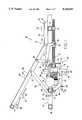
- FIG. 1is a diagrammatic sectional side view of part of a hospital bed embodying the present invention
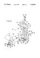
- FIG. 2is an exploded perspective view of a support arrangement for a drive motor which is a component of the bed of FIG. 1;
- FIG. 3is a fragmentary top view of a coupling mechanism which is part of the bed of FIG. 1;
- FIG. 4is a fragmentary sectional top view of the coupling mechanism of FIG. 3 with rotational parts thereof rotated by 90 degrees from the view of FIG. 3;
- FIG. 5is an exploded perspective view of the coupling mechanism of FIG. 3;
- FIG. 6is a partially exploded perspective view of the coupling mechanism of FIG. 3.
- FIGS. 7 and 8are similar perspective views of the coupling mechanism of FIG. 3 and show respective modes of operation in which the coupling mechanism is respectively engaged and disengaged.
- FIG. 1shows part of a hospital bed 10 which embodies the present invention.
- the bedincludes a metal frame 11, an articulatable patient support 12 provided on the frame 11, and an articulation control mechanism 13 for controlling the patient support 12.
- the frame 11includes two spaced side members 17, one of which is visible in FIG. 1, and two transverse members 18 and 19 which extend between and are fixably secured to the side members 17.
- the members 17-19are each made from a metal tube of square cross section, and could also be open section channels.
- the frame 11also includes a U-shaped member having a bight 22 which serves as a drive mechanism support and having two spaced legs (FIG. 2) which are not shown in FIG. 1 but which each extend leftwardly in FIG. 1 from a respective end of the bight 22 and each have an outer end fixedly secured to the transverse member 18.
- the articulatable patient support 12includes a central portion 26 slidably supported in a conventional and not-illustrated manner on the frame 11 for movement in directions parallel to the arrows 27, and a fowler portion 28 supported for pivotal movement about a pivot axis 29 relative to the central portion 26.
- the portion 26has its own movable frame which is not essential to the invention and which has been omitted from the drawings for clarity.
- the fowler portion 28is moveable from an approximately horizontally extending position upwardly through a range of progressively more inclined positions, one of which is shown in FIG. 1.
- the central portion 26 of the patient supporthas an approximately rectangular frame 31 and a patient support plate 32 secured on the upper side thereof, and the fowler portion 28 also has an approximately rectangular frame 33 and a support plate 34 thereon.
- a conventional mattress or padis normally provided on the support plates 32 and 34, but has been omitted in FIG. 1 for clarity.
- the central portion 26serves as a seat for a patient, and the fowler portion 28 supports the upper body of the patient.
- Each support link 36has one end pivotally supported at 37 on the fowler portion 28, and its opposite end pivotally supported at 38 on a side member 17 of the frame 11.
- a bracket 41is secured to the frame of the fowler portion 28, and supports a manually operable lever 42 for pivotal movement in the direction indicated by arrow 43.
- the lever 42controls a cable which extends to the lower portion of FIG. 1 and which has a sleeve 46 with an elongate wire 47 slidably supported therein. Movement of lever 42 causes the wire 47 to slide lengthwise within the sleeve 46.
- a U-shaped bracket 51 made of sheet metalhas a bight 52 and two spaced, parallel legs 53 and 54.
- Each of the legs 53 and 54has, at an end remote from the bight 52, a laterally outwardly projecting horizontal flange 56 which is disposed against an underside of the drive mechanism support 22, and has a further flange 57 which projects upwardly from an edge of the horizontal flange 56 and which is disposed against a side surface of the support 22.
- the bracket 51is fixedly secured to the support 22 by a pair of bolts 58 and associated nuts, each bolt 58 extending through aligned openings in the support 22 and flange 56.
- Each of the legs 53 and 54 of the bracket 51has a downwardly projecting flange portion 61, and a pivot pin 62 extends between and has its ends fixedly secured to the flange portions 61.
- An actuating plate 63has its lower end pivotally supported on the pivot pin 62, and has at its upper end two upwardly projecting and transversely spaced legs 67 and 68.
- a flange 69is secured to and projects downwardly from the legs 53 and 54 of the bracket, and has fixedly secured to it the end of sleeve 46 which is remote from bracket 41 and lever 42.
- the end of wire 47 remote from lever 42extends outwardly from the sleeve 46 and has its outer end coupled to the actuating plate 63.
- a thrust bearing 71is secured to the bight 52 of bracket 51, and a further bearing 72 is supported on the transverse member 19 of the frame 11.
- the bearing 72could alternatively be supported on the central portion 26, in which case it would move with central portion 26 with the shaft 73 sliding within it.
- a threaded shaft 73has its ends rotatably supported by the bearings 71 and 72, and is held against axial movement.
- a nut 76threadedly engages the shaft 73 between bearings 71 and 72, and a fowler link 77 has one end pivotally coupled at 78 to the nut 76 and its other end pivotally coupled at 79 to one end of a fowler control arm 81.
- the opposite end of the fowler control arm 81is welded to a cylindrical rod 82 which in turn is fixedly secured to the frame 33 of the fowler portion 28.
- the fowler control arm 81 and fowler link 77prevent the nut 76 from rotating about the axis of the threaded shaft 73.
- the nut 76moves axially along the shaft 73.
- Thiscauses the fowler portion 28 to pivot upwardly or downwardly relative to the frame 11, while the central portion 26 respectively slides leftwardly or rightwardly in FIG. 1.
- the articulation control mechanism 13includes a drive assembly 86 which is supported by the drive mechanism support 22 in a manner described in more detail below, and includes a releasable coupling 87 which can releasably drivingly couple the drive assembly 86 to the threaded shaft 73 in a manner described in more detail later.
- the drive assembly 86(FIG. 2) is a conventional commercially available part from the Motor Division of Emerson Electric Company of St. Louis, Missouri, as part number K37XYA223696, but will be briefly described to the extent necessary to ensure an understanding of the present invention. More specifically, the drive assembly 86 includes a unitary housing which has a portion 91 containing a reversible electrical motor and a portion 92 containing a reduction gear mechanism. A rotatable output shaft 93 projects outwardly from the portion 92 of the housing, and is rotatably driven by the motor through the reduction gear mechanism.
- the housing portion 92includes an annular collar 96 encircling the shaft 93, and four ribs 97 which project radially outwardly from the collar 96 at equally angularly spaced intervals.
- the shaft 93has an end portion 98 of reduced diameter, and has an axially extending keyway 99 in the portion between the collar 96 and end portion 98.
- the portion between collar 96 and end portion 98also has external threads 100 adjacent end portion 98.
- the drive assembly 86is supported on the drive mechanism support 22 by a support assembly 101.
- the support assembly 101includes a metal spacer 102 of rectangular shape which has spaced vertical holes 103 and 104 aligned with spaced vertical holes 106 and 107 provided through the support 22, the holes 106 and 107 being disposed between spaced vertical holes 108 and 109 in support 22 which each receive a respective one of the bolts 58 (FIG. 1).
- the spacer 102also has a hole 113 extending horizontally therethrough intermediate the holes 103 and 104.
- Two mounting plates 116are identical, except that one has an inverted orientation with respect to the other.
- the mounting plates 116each have spaced holes 117 and 118 which are aligned with the holes 103 and 104 in spacer 102, and have edge portions 121 and 122 bent at a right angle to the central portion so as to define flanges which project downwardly from opposite sides of the upper mounting plate and upwardly from opposite sides of the lower mounting plate.
- Each of the flanges 121 and 122has a pair of spaced cutouts 123 and 124.
- An isolator member 126which is a rectangular block of neoprene rubber, is disposed between the mounting plates 116 and has two vertical holes 127 and 128 which are aligned with the holes 117 and 118 in the mounting plates and which each have disposed therein a respective one of two metal spacer sleeves 131 and 132.
- Each of the spacer sleeves 131 and 132has a vertical height equal to the vertical height of the isolator member 126, and has each of its ends disposed against a respective one of the mounting plates 116.
- the isolator member 126also has two horizontally extending holes 133 and 134 which are spaced outwardly from the holes 127 and 128 and which are each aligned with a respective one of the cutouts 123 and 124.
- Two bolts 136 and 137each extend through one of the holes 106 and 107 in the support member 22, one of the holes 103 and 104 in the spacer member 102, one of the holes 117 and 118 in each of the mounting plates 116, and one of the sleeves 131 and 132 in the holes 127 and 128 of the isolator member 126, and each have a respective nut 138 or 139 on the lower end thereof to securely clamp all of these components to each other.
- Two identical tubular mounting posts 141 and 142are each made of nylon. As shown for the mounting post 142, each has end portions 143 and 144 of different diameter and a disk portion 146 which is disposed between and has a diameter greater than that of portions 143 and 144.
- the portion 143 of each mounting post 141 and 142extends into a respective one of the horizontal holes 133 and 134 in the isolator member 126, and has a length approximately equal to the width of the isolator member 126, the disk portion 146 of each mounting post being disposed against a side surface of the isolator member 126.
- Two bolts 148 and 149each extend through a respective washer 151 or 152 and through a respective one of the mounting posts 141 and 142, and each threaded engage a respective one of two not-illustrated threaded openings in the housing portion 92 of the drive assembly.
- the neoprene rubber isolator member 26provides both electrical and mechanical isolation for the drive assembly 86 with respect to metal support member 22.
- the releasable coupling 87 of FIG. 1is shown in more detail in FIGS. 3-6. It includes an annular metal spring holder 161 with an annular flange 162 which extends radially outwardly and an annular flange 163 which extends axially.
- the inside diameter of the spring holder 161is only slightly larger than the distance between the radially outer ends of opposite ribs 97 on the drive housing, and the spring holder 161 closely encircles the ribs 97.
- Six metal spring washerswhich serve as brake springs encircle the axial flange 163 of the spring holder 161. More or fewer spring washers could be used, depending on the requirements of the particular design.
- a brake washer 168encircles the ribs 97 on the side of springs 166 remote from the spring holder 161, but is held in a position radially spaced from the ribs through enlargement of its radially inner edge with a shallow annular recess 170 in a plastic brake disk 171.
- the brake disk 171has a central opening 172 with a diameter slightly larger than the diameter of the collar 96 on the drive housing, and has four rectangular notches 173 at equal angular intervals which each receive a respective one of the ribs 97.
- the brake disk 171is held against rotation with respect to the drive housing by the cooperation between the notches 173 and the ribs 97 on the housing.
- a brake cup 176 made of metalhas an axially extending cylindrical wall 178 with a radially extending wall 177 therein near one end, and also has a radially extending braking flange 179 at that end.
- the flange 179has an axially facing annular surface which slidably engages an axially facing annular surface on the brake disk 171.
- the output shaft 93 of the drive mechanismextends rotatably through a central opening in the radial wall 177.
- a conventional thrust bearing 181has two races 182 and 183 which encircle the output shaft 93, the race 182 being disposed against the radial wall 177 of the brake cup 176.
- a plurality of ball bearings or needle bearingsare disposed between the races.
- a metal driving member 186has a central opening 187 through which the output shaft 93 extends, the central opening 187 having a key slot containing a key 188 which engages the keyway 99 in the output shaft 93, thereby preventing relative rotation of the driving member 186 and output shaft 93.
- One side of the driving member 186engages the race 183 of the bearing 181, and the other side has a shallow circular recess 191.
- Three projections 192-194 at equal angular intervalsextend axially in a direction away from bearing 181.
- the driving member 186has an outside diameter which is substantially equal to the outside diameter of the axial wall 178 on brake cup 176.
- a helical clutch spring 196has an inside diameter which is slightly less than the outside diameters of driving member 186 and axial wall 178 of brake cup 176, is made of spring wire of square cross section, and closely encircles each of these two components.
- a nut 197is disposed in the recess 191 of driving member 186 and engages the threads 100 on output shaft 93, in order to maintain the driving member 186, bearing 181, brake cup 176, brake disk 171, brake washer 168, brake springs 166 and spring holder 161 in position on the housing portion 92.
- the nut 197is tightened sufficiently so that the brake springs 166 are axially compressed between the flange 162 of spring holder 161 and the brake washer 168, and thus the springs 166 continuously resiliently urge the brake disk 171 against the braking flange 179 on the brake cup 176, producing friction between them which tends to resist rotation of the brake cup 176 relative to the brake disk 171 and thus relative to the housing 92, because the ribs 97 thereon hold the brake disk 171 against rotation.
- a cup-like isolation member 201has an end wall 202, and has projecting axially outwardly from one side of the end wall 202 an annular wall which includes a portion 206 with an inside diameter slightly larger than the outside diameter of driving member 186 and a portion 107 with an inside diameter slightly greater than the outside diameter of helical clutch spring 196.
- An annular step 209 between the portions 206 and 207can engage an end of the clutch spring 196 in order to prevent any significant axial movement of the clutch spring 196.
- the outer end of the portion 207has a radially outwardly projecting annular flange 208.
- the end wall 202has a radial bore 211 extending transversely through it, and has a blind bore 212 extending axially into it on a side remote from wall portions 206 and 207.
- the isolation member 201is made of a durable and electrically nonconductive synthetic material, such as the material commercially available under the name DELRIN.
- a driven member 216is disposed within the portion 206 of the isolator member 201.
- the driven member 216is made of an insulating material, such as 30% glass-filled nylon.
- the driven member 216has a disk-like portion 217 which is disposed against end wall 202 and fixedly secured thereto by three not-illustrated screws, and has three axial projections 218 at equal angular intervals which extend toward the driving member 186 and are each disposed angularly between a respective pair of the projections 192-194 on the driving member 186.
- the driven member 216 and isolator member 201are shown as separate parts in the figures, it will be recognized that they could be a single integral component.
- the disk-like portion 217has a central opening which rotatably receives the reduced diameter portion 98 of output shaft 93.
- a rubber spider 221has an annular hub 222 which encircles the output shaft 93 at a location axially between the driving member 186 and driven member 216, and has six radially outwardly projecting arms 223 which are each located angularly between a respective one of the projections 192-194 on driving member 186 and a respective one of the projections 218 on the driven member 216.
- a sleeve-like metal decoupling member 226has an inside diameter slightly larger than the outside diameter of the end wall 202 of isolator member 201, and is axially slidably supported on the end of isolator member 201 having end wall 202.
- the decoupling member 226has at one end an annular axial lip 227, and has a radially outwardly projecting annular flange 228 adjacent the lip 227.
- the decoupling member 226also has two axially extending slots 231 and 232 on diametrically opposite sides thereof, and has two approximately rectangular notches extending axially into the end thereof remote from lip 227, the notches 233 and 234 being diametrically opposite each other.
- Two inclined ramp surfaces 236 and 237are provided on the same end of the decoupling member 226 as the notches, each of the ramp surfaces having ends which are axially offset with respect to each other and are respectively adjacent the notches 233 and 234.
- a metal pin 241extends through the radial bore 211 in the end wall 202 of isolator member 201 so that its ends are each disposed within one of the slots 231 and 232, and has rollers 242 and 243 rotatably supported on its ends within the slots and held in place by respective snap rings 244.
- the rollers 242 and 243are each made of a durable nonconductive synthetic material, such as DELRIN.
- the rollers 242 and 243each have a diameter which is slightly less than the width of the associated slot 231 or 232, so that the rollers 242 and 243 can roll on the walls of the slots.
- a helical compression spring 246encircles the isolator member 201, has one end disposed against the radial flange 208 on isolator member 201, and has its opposite end encircling lip 227 and disposed against radial flange 228 on the decoupling member 226.
- the spring 246yieldably urges the decoupling member 226 rightwardly in FIG. 4 relative to the isolator member 201, so that the rollers 242 and 243 are disposed at the left ends of the slots 231 and 232.
- the bearingincludes an outer race 251 with a flange which is secured by rivets 252 to the bight 52 of bracket 51.
- An inner race 253is provided within the outer race 251, and the races have facing frustoconical surfaces with cylindrical roller bearings 254 disposed therebetween.
- the threaded shaft 73has a nonthreaded end portion 256 of reduced diameter which is separated from the remainder of the shaft by a step 255, which extends through inner race 253, which has its outer end rotatably disposed in the blind bore 212 in isolator member 201, and which has extending through it between isolator member 201 and bearing 71 a transverse radial bore 257.
- a roller thrust bearing 258is disposed between the bight 52 of bracket 51 and the annular step 255 on shaft 73.
- a metal wing member 261has an annular hub 262 which encircles the end portion 256 of shaft 73 between isolator member 201 and bearing 71, and which has a transverse radial bore 263 therethrough.
- a pin 264is disposed in the bore 263 in wing member 261 and in the transverse bore 257 in the shaft 73 so as to prevent relative rotation therebetween.
- the wing member 261has two radially outwardly projecting wing portions 266 on diametrically opposite sides thereof, each wing portion 266 having an approximately rectangular cross section.
- the driving member 186When the reversible electric motor is energized and rotates the output shaft 93 of the drive assembly in a first direction, the driving member 186 is rotated in the same direction by the output shaft 93. In this direction of rotation, the friction between driving member 186 and clutch spring 196 tends to unwind the clutch spring 196 a small amount, which reduces the friction to a point where the driving member 186 rotates independently of the clutch spring 196, and thus also rotates relative to the brake cup 176, rotation of which is yieldably resisted by its frictional engagement with the brake disk 171 under the axial pressure of braking springs 166. It is also possible for the spring 196 to rotate with member 186 relative to brake cup 176.
- the thrust bearing 181facilitates rotation of the driving member 186 relative to brake cup 176 without friction therebetween.
- the axial projections 192-194 on the driving member 186cooperate with the projections 218 on the driven member 216 through the arms 223 of spider 221 to rotate the driven member 216 in synchronism with driving member 186, the driven member 216 in turn rotating the isolator member 201 to which it is fixedly secured.
- the spider 221provides vibration and shock damping to avoid stripping gears in the gear reduction mechanism, primarily during high-speed re-engagement.
- the decoupling member 226is rotated with the isolator member 201.
- the decoupling member 226is in the axial position shown in FIGS. 4 and 7, in which the two wings 266 on the wing member 261 engage the notches 233 and 234 in the decoupling member 226, so that the wing member 261 is rotated by the decoupling member 226 and in turn, through pin 264, rotates the threaded shaft 73.
- the nut 76will move axially along shaft 73 in a leftward direction in FIG. 1, which causes the fowler portion 28 to pivot upwardly about pivot axis 29 (clockwise in FIG. 1).
- the electric motoris de-energized to stop the fowler portion in this position.
- the weight of a patient on the fowler portion 28will tend to urge the nut 76 rightwardly in FIG. 1, which in turn will urge rotation of the shaft 73 in a second direction opposite the first direction.
- the forces generated by patient weight on the fowlercould, particularly in the case of a heavy patient, be sufficient to turn the rotor of the de-energized motor through the reduction gearing.
- the fowler 28would not remain in the position selected by the operator, but would pivot downwardly toward its horizontal position. This phenomena is effectively eliminated in the apparatus according to the present invention.
- the friction between the driving member 186 and spring 196will urge the spring in the direction which tightens the coils of the spring, thus causing the spring to tightly grip both the driving member 186 and the brake cup 176, thereby preventing the driving member 186 from rotating relative to the brake cup 176.
- the driving member 186thus can rotate in the reverse direction only if the torque applied to it is sufficient to overcome the friction between the braking surfaces on the brake disk 171 and flange 179 of the brake cup 176.
- the brake springs 166are selected to produce an axial force generating a degree of friction between these braking surfaces which is more than adequate to prevent rotation of the driving member 186 in response to downward forces applied to the fowler.
- the electric motoris energized in a manner causing it to rotationally drive the output shaft 93 in the second direction.
- the clutch spring 196will couple the driving member 186 to the brake cup 176 in the manner described above, but in the preferred embodiment the electric motor and reduction gearing are selected to provide an output torque sufficient to overcome the friction between the brake cup 176 and brake disk 171, and thus through the coupling assembly 87 the shaft 73 is rotated in the second direction by the motor so that the nut 76 moves progressively rightwardly in the FIG. 1 and lowers the fowler portion 28.
- the notches 233 and 234 thereinmove out of engagement with the wing portions 266 of the wing member 261, until the wing member 261 is axially offset from the decoupling member 226 and can freely rotate without any engagement with the decoupling member 226.
- the wing member 266 and shaft 73can freely rotate in response to the rotational forces being applied to the shaft 73 by the nut 76 and downward forces acting on the fowler portion 28.
- the fowler portion 28can be very rapidly lowered toward its horizontal position.
- the fowler portion 28could be manually raised to a greater degree of inclination. In either case, when the fowler portion 28 has been moved to a desired position, the lever 42 is released.
- the spring 246urges the decoupling member 226 rightwardly, which in turn pivots the actuating plate 63 clockwise in FIG. 1 so that it pulls the wire 47 rightwardly and restores the lever 42 to its original position. It is possible to also provide an additional not-illustrated helical expansion spring which extends between the plate 63 and the bight 52 of the bracket, so that the legs 67 and 68 of plate 63 are pulled to a position spaced from the flange 228 in which they do not rub against the rotating flange to thereby avoid wear and audible noise.
- the decoupling member 226will immediately move to its rightmost position (shown in FIGS. 3 and 7), in which the wing portions 266 are fully engaged with the notches 233 and 234.
- the wing portions 266will be angularly offset from the notches and will move into engagement with the ramp surfaces 236 and 237, as shown in FIG. 8.
- the shaft 73 and wing member 261will rotate clockwise in FIG. 8, causing the wing portions 266 to slide along the ramp surfaces until they are aligned with the notches 233 and 234. As shown in FIG.
- each notchhas side surfaces 268 and 269 which, due to the inclination of the ramp surfaces, are of different length.
- the inclination of the ramp surfacesis such that the wing portions 266 each rotate into alignment with a respective notch from the side of the notch having the shorter side surface 268, and thus the wing portions 266 cannot rotate past the notches 233 and 234 because each would engage the longer side surface 269 on the opposite side of the notch and thus have its rotation halted.
- the inclined ramp surfaces and the different length side surfaces 268 and 269thus ensure that the wing portions 266 and the notches in decoupling member 226 promptly and reliably move into alignment when the lever 42 is released, even when the shaft 73 and wings are turning at a relatively high speed.
- the spring 246then moves the decoupling member 226 rightwardly the rest of the way back to its original position, in which the wing portions 266 are fully received within the respective notches 233 and 234.
Landscapes
- Health & Medical Sciences (AREA)
- General Health & Medical Sciences (AREA)
- Nursing (AREA)
- Life Sciences & Earth Sciences (AREA)
- Animal Behavior & Ethology (AREA)
- Public Health (AREA)
- Veterinary Medicine (AREA)
- Invalid Beds And Related Equipment (AREA)
Abstract
Description
Claims (22)
Priority Applications (1)
| Application Number | Priority Date | Filing Date | Title |
|---|---|---|---|
| US07/964,582US5329657A (en) | 1992-10-21 | 1992-10-21 | Quick release coupling for head section of a hospital bed |
Applications Claiming Priority (1)
| Application Number | Priority Date | Filing Date | Title |
|---|---|---|---|
| US07/964,582US5329657A (en) | 1992-10-21 | 1992-10-21 | Quick release coupling for head section of a hospital bed |
Publications (1)
| Publication Number | Publication Date |
|---|---|
| US5329657Atrue US5329657A (en) | 1994-07-19 |
Family
ID=25508722
Family Applications (1)
| Application Number | Title | Priority Date | Filing Date |
|---|---|---|---|
| US07/964,582Expired - LifetimeUS5329657A (en) | 1992-10-21 | 1992-10-21 | Quick release coupling for head section of a hospital bed |
Country Status (1)
| Country | Link |
|---|---|
| US (1) | US5329657A (en) |
Cited By (92)
| Publication number | Priority date | Publication date | Assignee | Title |
|---|---|---|---|---|
| US5423097A (en)* | 1993-07-01 | 1995-06-13 | Stryker Corporation | Emergency drop fowler and gatch |
| US5444880A (en)* | 1993-11-03 | 1995-08-29 | Hill-Rom Company, Inc. | Bed with emergency head release and automatic knee down |
| US5537701A (en)* | 1994-03-15 | 1996-07-23 | Maxwell Products, Inc. | Adjustable articulated bed |
| EP0685662A3 (en)* | 1994-05-31 | 1996-08-21 | Linak As | A linear actuator. |
| FR2746002A1 (en)* | 1996-03-15 | 1997-09-19 | Sehp Matifas | Back=up actuating mechanism for linear electrical motor of hospital bed |
| US5774914A (en)* | 1996-01-05 | 1998-07-07 | Stryker Corporation | Maternity bed |
| US5862549A (en)* | 1996-01-05 | 1999-01-26 | Stryker Corporation | Maternity bed |
| AT405368B (en)* | 1995-08-01 | 1999-07-26 | Vaught Sagel Gmbh & Co | Sick or nursing bed |
| US5926878A (en)* | 1996-01-05 | 1999-07-27 | Stryker Corporation | Maternity bed |
| US5957798A (en)* | 1997-09-10 | 1999-09-28 | Gec-Marconi Aerospace Inc. | Fail-free actuator assembly |
| US6209463B1 (en)* | 1999-03-12 | 2001-04-03 | United Metal Fabricators, Inc. | Medical examination table |
| US6212713B1 (en) | 1999-08-09 | 2001-04-10 | Midmark Corporation | Examination table with sliding back section |
| US6212970B1 (en) | 1999-08-24 | 2001-04-10 | Teleflex Incorporated | Pedal assembly with adjustable pad |
| US6216295B1 (en) | 1997-04-17 | 2001-04-17 | L & P Property Management Company | Adjustable bed |
| BE1013033A3 (en)* | 1999-03-22 | 2001-08-07 | Imhold Nv | Bed frame |
| US6321617B1 (en) | 2000-06-08 | 2001-11-27 | Jeffrey Schwyn | Adjustable pedal assembly |
| GB2364902A (en)* | 2000-07-21 | 2002-02-13 | Christopher John Hooker | Lifting apparatus for a bed |
| FR2813173A1 (en)* | 2000-08-24 | 2002-03-01 | Pierre Moine | Mechanism for adjusting distance between back of armchair or sofa mounted on castors and wall comprises rod fixed to wall and mounted on pivot on back, inclined screw jack attached to rod and base of sofa allowing sofa to be pushed outwards |
| USD458780S1 (en) | 2001-06-19 | 2002-06-18 | The Brewer Company, Llc | Drawer front face |
| USD461900S1 (en) | 2001-06-19 | 2002-08-20 | The Brewer Company, Llc | Top for a medical examination table |
| USD461899S1 (en) | 2001-06-19 | 2002-08-20 | The Brewer Company, Llc | Medical examination table |
| USD462674S1 (en) | 2001-06-19 | 2002-09-10 | The Brewer Company, Llc | Medical examination table cabinet |
| USD463861S1 (en) | 2001-06-19 | 2002-10-01 | The Brewer Company, Llc | Stirrup for a medical examination table |
| US6499159B1 (en)* | 1999-06-28 | 2002-12-31 | Guenter Schmitt | Apparatus for coupling a drive to an adjustable patient positioning plate in a medical system |
| US6550084B2 (en) | 2001-06-19 | 2003-04-22 | The Brewer Company, Llc | Medical examination table step |
| WO2003033946A1 (en)* | 2001-10-03 | 2003-04-24 | Linak A/S | An actuator |
| US6575412B2 (en)* | 2000-09-11 | 2003-06-10 | Kaefer Isoliertechnik Gmbh & Co. Kg | Support for pipelines and process for mounting such a support |
| US6654974B2 (en) | 2000-06-02 | 2003-12-02 | Hill-Rom Services, Inc. | Foot support for a patient support |
| US6684420B2 (en) | 2001-04-27 | 2004-02-03 | Hill-Rom Services, Inc. | Crib apparatus |
| US6757924B2 (en) | 1999-08-23 | 2004-07-06 | Hill-Rom Services, Inc. | Bed having a removable foot section |
| US20040128765A1 (en)* | 1999-12-29 | 2004-07-08 | Hill-Rom Services, Inc. | Foot controls for a bed |
| US20040148704A1 (en)* | 2003-02-05 | 2004-08-05 | Tekulve Daniel R. | Articulating bed frame |
| US6772456B2 (en) | 1995-09-13 | 2004-08-10 | Hill-Rom Services, Inc. | Portable device for patient pullup, rollover, and transfer and methods thereof |
| USD496462S1 (en) | 2003-09-29 | 2004-09-21 | The Brewer Company, Llc | Medical examination table |
| USD507905S1 (en) | 2003-09-29 | 2005-08-02 | The Brewer Company, Llc | Lifting column |
| US20050283914A1 (en)* | 2004-06-25 | 2005-12-29 | Roussy Richard B | Patient bed with CPR system |
| EP1637775A1 (en)* | 2004-09-20 | 2006-03-22 | Ab Skf | Linear actuator with manual actuation for emergency |
| US20060117484A1 (en)* | 2004-12-03 | 2006-06-08 | Derenne Richard A | Patient support apparatus with removable foot section |
| US20060117485A1 (en)* | 2004-12-03 | 2006-06-08 | Brophy Joseph T | Maternity bed foot support and abduction assembly |
| US7083355B2 (en) | 2003-09-29 | 2006-08-01 | The Brewer Company, Llc | Stirrup support indexer for a medical examination table |
| US20060168727A1 (en)* | 2005-01-31 | 2006-08-03 | Hill-Rom Services, Inc. | Birthing support apparatus |
| US7093313B2 (en) | 2003-09-29 | 2006-08-22 | The Brewer Company, Llc | Headrest linkage |
| US7111338B2 (en) | 2002-06-17 | 2006-09-26 | Hill-Rom Services, Inc. | Apparatus for pulling patient up in bed |
| US20060225215A1 (en)* | 2004-12-03 | 2006-10-12 | Stryker Corporation | Calf support assembly for a maternity bed foot support and abduction assembly |
| US20060243075A1 (en)* | 2005-05-02 | 2006-11-02 | Hiwin Mikrosystem Corp. | Linear actuator with quick release mechanism |
| USD535544S1 (en) | 2005-07-28 | 2007-01-23 | The Brewer Company, Llc | Grab bar |
| US20070113345A1 (en)* | 2005-11-17 | 2007-05-24 | Hill-Rom Services, Inc. | Birthing bed foot support release handle |
| US20070145806A1 (en)* | 2005-12-23 | 2007-06-28 | Robert Wilder | Linear actuator having a clutch for an airline seat |
| US20070144279A1 (en)* | 2005-12-27 | 2007-06-28 | Chou-Hsin Wu | Quick-Releasing Linear Actuator |
| US20070174965A1 (en)* | 2005-12-19 | 2007-08-02 | Stryker Corporation | Hospital bed |
| US7290299B2 (en) | 2004-01-09 | 2007-11-06 | Votel Thomas W | Device and method for positioning patients |
| US7350249B2 (en) | 2003-09-29 | 2008-04-01 | The Brewer Company, Llc | Leg rest and kneeler assembly for a medical examination table |
| USD569520S1 (en) | 2005-07-28 | 2008-05-20 | Debraal Jack A | Medical examination table cabinet |
| US7386899B2 (en) | 2005-09-14 | 2008-06-17 | Midmark Corporation | Medical examination table with pullout step |
| USD574959S1 (en) | 2005-07-28 | 2008-08-12 | Debraal Jack A | Medical examination table |
| USD574960S1 (en) | 2005-07-28 | 2008-08-12 | Parrish Vanessa B | Medical examination table top |
| JP2008249051A (en)* | 2007-03-30 | 2008-10-16 | Mitsuba Corp | Linear actuator |
| US20090031498A1 (en)* | 2007-08-01 | 2009-02-05 | Stryker Corporation | Cpr drop mechanism for a hospital bed |
| US7513000B2 (en) | 2005-07-28 | 2009-04-07 | The Brewer Company, Llc | Medical examination table |
| CN100552263C (en)* | 2004-10-15 | 2009-10-21 | 利纳克有限公司 | linear actuator |
| WO2009068009A3 (en)* | 2007-11-29 | 2009-12-03 | Schuele Robert | Drive system comprising components that can be combined to form modules |
| US20100050523A1 (en)* | 2008-08-26 | 2010-03-04 | Helms James M | Safety release mechanism for use with a linear motor turning a ball screw |
| US7725964B2 (en) | 2004-08-27 | 2010-06-01 | Hill-Rom Services, Inc. | Apparatus with patient adjustment device coupled to architectural system |
| US20100139427A1 (en)* | 2005-09-28 | 2010-06-10 | Zentaro Yamaguchi | Linear Actuator |
| US20100206112A1 (en)* | 2009-02-19 | 2010-08-19 | Hiwin Mikrosystem Corp. | Linear actuator |
| US20110224475A1 (en)* | 2010-02-12 | 2011-09-15 | Andries Nicolaas Schreuder | Robotic mobile anesthesia system |
| US20110274568A1 (en)* | 2010-05-10 | 2011-11-10 | New Widetech Industries Co., Ltd. | Blower for a dehumidifier |
| CN102410350A (en)* | 2011-08-03 | 2012-04-11 | 力纳克传动系统(深圳)有限公司 | Quick-release driver |
| US20120096963A1 (en)* | 2010-10-25 | 2012-04-26 | Moteck Electric Corp. | Electric push rod and release mechanism combination structure |
| US20120240696A1 (en)* | 2009-12-04 | 2012-09-27 | Jeppe Christian Bastholm | Linear actuator |
| US8336138B2 (en) | 2003-03-18 | 2012-12-25 | Hill-Rom Services, Inc. | Radial arm system for patient care equipment |
| US20140260730A1 (en)* | 2013-03-13 | 2014-09-18 | Timotion Technology Co., Ltd. | Actuator with quick-release mechanism |
| US20140312725A1 (en)* | 2011-11-09 | 2014-10-23 | Dewertokin Gmbh | Electric linear drive, in particular for adjusting furniture used for sitting or lying down |
| US20150033885A1 (en)* | 2013-08-05 | 2015-02-05 | Limoss US, LLC | Linear Actuator |
| US9038216B2 (en) | 2005-07-28 | 2015-05-26 | The Brewer Company, Llc | Medical examination table |
| US9295598B2 (en)* | 2011-12-09 | 2016-03-29 | Stryker Corporation | Patient support backrest release and actuator assembly |
| US9351890B2 (en) | 2013-03-15 | 2016-05-31 | Stryker Corporation | Medical support apparatus |
| US20170331350A1 (en)* | 2014-08-19 | 2017-11-16 | Linak A/S | Linear actuator |
| US20190223608A1 (en)* | 2016-08-31 | 2019-07-25 | Keeson Technology Corporation Limited | Waist ejection mechanism applied to electric bed and electric bed comprising same |
| US10470954B2 (en) | 2016-06-28 | 2019-11-12 | Stryker Corporation | Patient support apparatus with deck section link |
| US20200008994A1 (en)* | 2014-04-18 | 2020-01-09 | Kreg Medical, Inc. | Patient Support with Stand-Up and Sit Features |
| US10729246B2 (en) | 2017-12-21 | 2020-08-04 | Stryker Corporation | Person support apparatus with shear-reducing pivot assembly |
| US11266554B2 (en) | 2017-09-08 | 2022-03-08 | Kreg Medical, Inc. | Bed base frame |
| US11376177B2 (en)* | 2013-02-05 | 2022-07-05 | Hill-Rom Services, Inc. | Powered width expansion of articulated bed deck |
| DE102022114310A1 (en) | 2021-08-11 | 2023-02-16 | Timotion Technology Co., Ltd. | Linear actuator and centrifugal safety device therefor |
| US20230072650A1 (en)* | 2021-09-09 | 2023-03-09 | Nantong Shunlong Physical Therapy Equipment Co., Ltd. | Transmission device for lifting sickbed |
| US20230200546A1 (en)* | 2021-12-23 | 2023-06-29 | Chuan-Hang Shih | Foldable electric bed |
| TWI824447B (en)* | 2021-08-11 | 2023-12-01 | 第一傳動科技股份有限公司 | Linear actuator and centrifugal safety device thereof |
| US20240023720A1 (en)* | 2022-07-21 | 2024-01-25 | Chuan-Hang Shih | Electric bed |
| DE202024101398U1 (en) | 2023-07-25 | 2024-04-05 | Timotion Technology Co., Ltd. | Linear actuator with damping mechanism |
| US12053421B2 (en) | 2021-03-31 | 2024-08-06 | Hill-Rom Services, Inc. | Hospital bed CPR activation assembly |
| US12208041B2 (en) | 2008-06-27 | 2025-01-28 | Kreg Medical, Inc. | Bed with frame assembly |
Citations (4)
| Publication number | Priority date | Publication date | Assignee | Title |
|---|---|---|---|---|
| US4038709A (en)* | 1975-12-24 | 1977-08-02 | Kerwit Medical Products, Inc. | Dual hydraulic hospital bed |
| US4222131A (en)* | 1978-09-15 | 1980-09-16 | Chemed Corporation | Hook type fowler for hospital stretchers |
| US4346487A (en)* | 1980-04-25 | 1982-08-31 | Whittaker Medical Manufacturing Company | Quick release manual type Fowler for hospital stretchers |
| US4559655A (en)* | 1982-08-11 | 1985-12-24 | Hill-Rom Company, Inc. | Bed having articulated frame |
- 1992
- 1992-10-21USUS07/964,582patent/US5329657A/ennot_activeExpired - Lifetime
Patent Citations (4)
| Publication number | Priority date | Publication date | Assignee | Title |
|---|---|---|---|---|
| US4038709A (en)* | 1975-12-24 | 1977-08-02 | Kerwit Medical Products, Inc. | Dual hydraulic hospital bed |
| US4222131A (en)* | 1978-09-15 | 1980-09-16 | Chemed Corporation | Hook type fowler for hospital stretchers |
| US4346487A (en)* | 1980-04-25 | 1982-08-31 | Whittaker Medical Manufacturing Company | Quick release manual type Fowler for hospital stretchers |
| US4559655A (en)* | 1982-08-11 | 1985-12-24 | Hill-Rom Company, Inc. | Bed having articulated frame |
Cited By (162)
| Publication number | Priority date | Publication date | Assignee | Title |
|---|---|---|---|---|
| US5423097A (en)* | 1993-07-01 | 1995-06-13 | Stryker Corporation | Emergency drop fowler and gatch |
| US5444880A (en)* | 1993-11-03 | 1995-08-29 | Hill-Rom Company, Inc. | Bed with emergency head release and automatic knee down |
| US5537701A (en)* | 1994-03-15 | 1996-07-23 | Maxwell Products, Inc. | Adjustable articulated bed |
| US5577280A (en)* | 1994-03-15 | 1996-11-26 | Maxwell Products, Inc. | Snap-together adjustable, articulated bed |
| EP0685662A3 (en)* | 1994-05-31 | 1996-08-21 | Linak As | A linear actuator. |
| AT405368B (en)* | 1995-08-01 | 1999-07-26 | Vaught Sagel Gmbh & Co | Sick or nursing bed |
| US6772456B2 (en) | 1995-09-13 | 2004-08-10 | Hill-Rom Services, Inc. | Portable device for patient pullup, rollover, and transfer and methods thereof |
| US5774914A (en)* | 1996-01-05 | 1998-07-07 | Stryker Corporation | Maternity bed |
| US5862549A (en)* | 1996-01-05 | 1999-01-26 | Stryker Corporation | Maternity bed |
| US5926878A (en)* | 1996-01-05 | 1999-07-27 | Stryker Corporation | Maternity bed |
| FR2746002A1 (en)* | 1996-03-15 | 1997-09-19 | Sehp Matifas | Back=up actuating mechanism for linear electrical motor of hospital bed |
| US6216295B1 (en) | 1997-04-17 | 2001-04-17 | L & P Property Management Company | Adjustable bed |
| US5957798A (en)* | 1997-09-10 | 1999-09-28 | Gec-Marconi Aerospace Inc. | Fail-free actuator assembly |
| US6209463B1 (en)* | 1999-03-12 | 2001-04-03 | United Metal Fabricators, Inc. | Medical examination table |
| BE1013033A3 (en)* | 1999-03-22 | 2001-08-07 | Imhold Nv | Bed frame |
| US6499159B1 (en)* | 1999-06-28 | 2002-12-31 | Guenter Schmitt | Apparatus for coupling a drive to an adjustable patient positioning plate in a medical system |
| US6212713B1 (en) | 1999-08-09 | 2001-04-10 | Midmark Corporation | Examination table with sliding back section |
| US7073221B2 (en) | 1999-08-23 | 2006-07-11 | Hill-Rom Services, Inc. | Bed having a removable foot section |
| US6757924B2 (en) | 1999-08-23 | 2004-07-06 | Hill-Rom Services, Inc. | Bed having a removable foot section |
| US20040226092A1 (en)* | 1999-08-23 | 2004-11-18 | Hill-Rom Services, Inc. | Bed having a removable foot section |
| US7464421B2 (en) | 1999-08-23 | 2008-12-16 | Hill-Rom Services, Inc. | Bed having a removable foot section |
| US6212970B1 (en) | 1999-08-24 | 2001-04-10 | Teleflex Incorporated | Pedal assembly with adjustable pad |
| US7171708B2 (en) | 1999-12-29 | 2007-02-06 | Hill-Rom Services, Inc. | Foot controls for a bed |
| US6978500B2 (en) | 1999-12-29 | 2005-12-27 | Hill-Rom Services, Inc. | Foot controls for a bed |
| US20040128765A1 (en)* | 1999-12-29 | 2004-07-08 | Hill-Rom Services, Inc. | Foot controls for a bed |
| US20050144723A1 (en)* | 2000-06-02 | 2005-07-07 | Hill-Rom Services, Inc. | Patient support |
| US6857153B2 (en) | 2000-06-02 | 2005-02-22 | Hill-Rom Services, Inc. | Patient support having a light assembly |
| US7469433B2 (en) | 2000-06-02 | 2008-12-30 | Hill-Rom Services, Inc. | Patient support with variable length actuator and release mechanism for lowering a sectional support surface |
| US6654974B2 (en) | 2000-06-02 | 2003-12-02 | Hill-Rom Services, Inc. | Foot support for a patient support |
| US6854145B2 (en) | 2000-06-02 | 2005-02-15 | Hill-Rom Services, Inc. | Patient support |
| US20040093672A1 (en)* | 2000-06-02 | 2004-05-20 | Hill-Rom Services, Inc. | Patient support |
| US6321617B1 (en) | 2000-06-08 | 2001-11-27 | Jeffrey Schwyn | Adjustable pedal assembly |
| GB2364902B (en)* | 2000-07-21 | 2004-06-23 | Christopher John Hooker | Lifting apparatus for a bed |
| GB2364902A (en)* | 2000-07-21 | 2002-02-13 | Christopher John Hooker | Lifting apparatus for a bed |
| FR2813173A1 (en)* | 2000-08-24 | 2002-03-01 | Pierre Moine | Mechanism for adjusting distance between back of armchair or sofa mounted on castors and wall comprises rod fixed to wall and mounted on pivot on back, inclined screw jack attached to rod and base of sofa allowing sofa to be pushed outwards |
| US6575412B2 (en)* | 2000-09-11 | 2003-06-10 | Kaefer Isoliertechnik Gmbh & Co. Kg | Support for pipelines and process for mounting such a support |
| US20040244109A1 (en)* | 2001-04-27 | 2004-12-09 | Koenig John W. | Crib apparatus |
| US6684420B2 (en) | 2001-04-27 | 2004-02-03 | Hill-Rom Services, Inc. | Crib apparatus |
| USD463861S1 (en) | 2001-06-19 | 2002-10-01 | The Brewer Company, Llc | Stirrup for a medical examination table |
| USD461900S1 (en) | 2001-06-19 | 2002-08-20 | The Brewer Company, Llc | Top for a medical examination table |
| USD462674S1 (en) | 2001-06-19 | 2002-09-10 | The Brewer Company, Llc | Medical examination table cabinet |
| USD461899S1 (en) | 2001-06-19 | 2002-08-20 | The Brewer Company, Llc | Medical examination table |
| USD458780S1 (en) | 2001-06-19 | 2002-06-18 | The Brewer Company, Llc | Drawer front face |
| US6550084B2 (en) | 2001-06-19 | 2003-04-22 | The Brewer Company, Llc | Medical examination table step |
| WO2003033946A1 (en)* | 2001-10-03 | 2003-04-24 | Linak A/S | An actuator |
| US20040194564A1 (en)* | 2001-10-03 | 2004-10-07 | Nielsen Jens Jorgen | Actuator |
| US7047834B2 (en)* | 2001-10-03 | 2006-05-23 | Linak A/S | Actuator |
| CN100381731C (en)* | 2001-10-03 | 2008-04-16 | 利纳克有限公司 | driver |
| US7111338B2 (en) | 2002-06-17 | 2006-09-26 | Hill-Rom Services, Inc. | Apparatus for pulling patient up in bed |
| US6826793B2 (en)* | 2003-02-05 | 2004-12-07 | Daniel R. Tekulve | Articulating bed frame |
| US20080250562A1 (en)* | 2003-02-05 | 2008-10-16 | Tekulve Daniel R | Articulating bed frame |
| US7257850B1 (en) | 2003-02-05 | 2007-08-21 | Med-Mizer, Inc. | Articulating bed frame |
| US20040148704A1 (en)* | 2003-02-05 | 2004-08-05 | Tekulve Daniel R. | Articulating bed frame |
| US8336138B2 (en) | 2003-03-18 | 2012-12-25 | Hill-Rom Services, Inc. | Radial arm system for patient care equipment |
| US7350249B2 (en) | 2003-09-29 | 2008-04-01 | The Brewer Company, Llc | Leg rest and kneeler assembly for a medical examination table |
| US7093313B2 (en) | 2003-09-29 | 2006-08-22 | The Brewer Company, Llc | Headrest linkage |
| US7083355B2 (en) | 2003-09-29 | 2006-08-01 | The Brewer Company, Llc | Stirrup support indexer for a medical examination table |
| USD496462S1 (en) | 2003-09-29 | 2004-09-21 | The Brewer Company, Llc | Medical examination table |
| USD507905S1 (en) | 2003-09-29 | 2005-08-02 | The Brewer Company, Llc | Lifting column |
| US7290299B2 (en) | 2004-01-09 | 2007-11-06 | Votel Thomas W | Device and method for positioning patients |
| US20050283914A1 (en)* | 2004-06-25 | 2005-12-29 | Roussy Richard B | Patient bed with CPR system |
| US7055195B2 (en) | 2004-06-25 | 2006-06-06 | Carroll Hospital Group, Inc. | Patient bed with CPR system |
| US7725964B2 (en) | 2004-08-27 | 2010-06-01 | Hill-Rom Services, Inc. | Apparatus with patient adjustment device coupled to architectural system |
| EP1637775A1 (en)* | 2004-09-20 | 2006-03-22 | Ab Skf | Linear actuator with manual actuation for emergency |
| US20060081079A1 (en)* | 2004-09-20 | 2006-04-20 | Victor Jaecklin | Linear drive with emergency adjustment possibility |
| CN100552263C (en)* | 2004-10-15 | 2009-10-21 | 利纳克有限公司 | linear actuator |
| US20080307579A1 (en)* | 2004-12-03 | 2008-12-18 | Stryker Corporation | Patient support apparatus with removable foot section |
| US20060225215A1 (en)* | 2004-12-03 | 2006-10-12 | Stryker Corporation | Calf support assembly for a maternity bed foot support and abduction assembly |
| US20060117484A1 (en)* | 2004-12-03 | 2006-06-08 | Derenne Richard A | Patient support apparatus with removable foot section |
| US7581266B2 (en) | 2004-12-03 | 2009-09-01 | Stryker Corporation | Calf support assembly for a maternity bed foot support and abduction assembly |
| US20060117485A1 (en)* | 2004-12-03 | 2006-06-08 | Brophy Joseph T | Maternity bed foot support and abduction assembly |
| US7735168B2 (en) | 2004-12-03 | 2010-06-15 | Stryker Corporation | Patient support apparatus with removable foot section |
| US7127756B2 (en) | 2004-12-03 | 2006-10-31 | Stryker Corporation | Maternity bed foot support and abduction assembly |
| US7412739B2 (en) | 2004-12-03 | 2008-08-19 | Stryker Corporation | Patient support apparatus with removable foot section |
| US7536734B2 (en) | 2005-01-31 | 2009-05-26 | Hill-Rom Services, Inc. | Birthing support apparatus |
| US20060168727A1 (en)* | 2005-01-31 | 2006-08-03 | Hill-Rom Services, Inc. | Birthing support apparatus |
| US20060243075A1 (en)* | 2005-05-02 | 2006-11-02 | Hiwin Mikrosystem Corp. | Linear actuator with quick release mechanism |
| USD569520S1 (en) | 2005-07-28 | 2008-05-20 | Debraal Jack A | Medical examination table cabinet |
| USD574960S1 (en) | 2005-07-28 | 2008-08-12 | Parrish Vanessa B | Medical examination table top |
| USD574959S1 (en) | 2005-07-28 | 2008-08-12 | Debraal Jack A | Medical examination table |
| US8479329B2 (en) | 2005-07-28 | 2013-07-09 | The Brewer Company, Llc | Medical examination table |
| US9038216B2 (en) | 2005-07-28 | 2015-05-26 | The Brewer Company, Llc | Medical examination table |
| US7513000B2 (en) | 2005-07-28 | 2009-04-07 | The Brewer Company, Llc | Medical examination table |
| US7845033B2 (en) | 2005-07-28 | 2010-12-07 | The Brewer Company, Llc | Medical examination table |
| US8096006B2 (en) | 2005-07-28 | 2012-01-17 | The Brewer Company, Llc | Medical examination table |
| USD535544S1 (en) | 2005-07-28 | 2007-01-23 | The Brewer Company, Llc | Grab bar |
| US7386899B2 (en) | 2005-09-14 | 2008-06-17 | Midmark Corporation | Medical examination table with pullout step |
| US20100139427A1 (en)* | 2005-09-28 | 2010-06-10 | Zentaro Yamaguchi | Linear Actuator |
| US8024987B2 (en)* | 2005-09-28 | 2011-09-27 | Mitsuba Corporation | Linear actuator |
| US7757317B2 (en) | 2005-11-17 | 2010-07-20 | Hill-Rom Services, Inc. | Stowing birthing bed foot section |
| US7669259B2 (en) | 2005-11-17 | 2010-03-02 | Hill-Rom Services, Inc. | Stowing birthing bed foot section |
| US7657953B2 (en) | 2005-11-17 | 2010-02-09 | Hill-Rom Services, Inc. | Birthing bed calf support |
| US7676868B2 (en) | 2005-11-17 | 2010-03-16 | Hill-Rom Services, Inc. | Birthing bed foot support release handle |
| US8079101B2 (en) | 2005-11-17 | 2011-12-20 | Hill-Rom Services, Inc. | Over-molded limb support |
| US8640287B2 (en) | 2005-11-17 | 2014-02-04 | Hill-Rom Services, Inc. | Patient-support apparatus with a locking deck section |
| US8117697B2 (en) | 2005-11-17 | 2012-02-21 | Hill-Rom Services, Inc. | Patient-support apparatus with a locking deck section |
| US20070113345A1 (en)* | 2005-11-17 | 2007-05-24 | Hill-Rom Services, Inc. | Birthing bed foot support release handle |
| US8327480B2 (en) | 2005-11-17 | 2012-12-11 | Hill-Rom Services, Inc. | Birthing bed lift off foot section |
| US20100251484A1 (en)* | 2005-11-17 | 2010-10-07 | Reckelhoff Jerome E | Over-molded limb support |
| US20070143926A1 (en)* | 2005-11-17 | 2007-06-28 | Hill-Rom Services, Inc. | Birthing bed calf support |
| US20070174965A1 (en)* | 2005-12-19 | 2007-08-02 | Stryker Corporation | Hospital bed |
| US8006332B2 (en) | 2005-12-19 | 2011-08-30 | Stryker Corporation | Hospital bed |
| US20070145806A1 (en)* | 2005-12-23 | 2007-06-28 | Robert Wilder | Linear actuator having a clutch for an airline seat |
| US20070144279A1 (en)* | 2005-12-27 | 2007-06-28 | Chou-Hsin Wu | Quick-Releasing Linear Actuator |
| US7594450B2 (en)* | 2005-12-27 | 2009-09-29 | Jaeger Industrial Co., Ltd. | Quick-releasing linear actuator |
| JP2008249051A (en)* | 2007-03-30 | 2008-10-16 | Mitsuba Corp | Linear actuator |
| US8402854B2 (en)* | 2007-03-30 | 2013-03-26 | Mitsuba Corporation | Linear actuator |
| US20100107790A1 (en)* | 2007-03-30 | 2010-05-06 | Zentaro Yamaguchi | Linear actuator |
| US7836531B2 (en) | 2007-08-01 | 2010-11-23 | Stryker Corporation | CPR drop mechanism for a hospital bed |
| US20090031498A1 (en)* | 2007-08-01 | 2009-02-05 | Stryker Corporation | Cpr drop mechanism for a hospital bed |
| WO2009068009A3 (en)* | 2007-11-29 | 2009-12-03 | Schuele Robert | Drive system comprising components that can be combined to form modules |
| US20100300227A1 (en)* | 2007-11-29 | 2010-12-02 | Robert Schuele | Drive system comprising components that can be combined to form modules |
| US12208041B2 (en) | 2008-06-27 | 2025-01-28 | Kreg Medical, Inc. | Bed with frame assembly |
| US20100050523A1 (en)* | 2008-08-26 | 2010-03-04 | Helms James M | Safety release mechanism for use with a linear motor turning a ball screw |
| US20100206112A1 (en)* | 2009-02-19 | 2010-08-19 | Hiwin Mikrosystem Corp. | Linear actuator |
| US20120240696A1 (en)* | 2009-12-04 | 2012-09-27 | Jeppe Christian Bastholm | Linear actuator |
| US8875592B2 (en)* | 2009-12-04 | 2014-11-04 | Linak A/S | Linear actuator |
| US20110224475A1 (en)* | 2010-02-12 | 2011-09-15 | Andries Nicolaas Schreuder | Robotic mobile anesthesia system |
| US20110274568A1 (en)* | 2010-05-10 | 2011-11-10 | New Widetech Industries Co., Ltd. | Blower for a dehumidifier |
| US20120096963A1 (en)* | 2010-10-25 | 2012-04-26 | Moteck Electric Corp. | Electric push rod and release mechanism combination structure |
| US8646348B2 (en)* | 2010-10-25 | 2014-02-11 | Moteck Electric Corp. | Electric push rod and release mechanism combination structure |
| CN102410350B (en)* | 2011-08-03 | 2014-08-27 | 力纳克传动系统(深圳)有限公司 | Quick-release driver |
| CN102410350A (en)* | 2011-08-03 | 2012-04-11 | 力纳克传动系统(深圳)有限公司 | Quick-release driver |
| US20140312725A1 (en)* | 2011-11-09 | 2014-10-23 | Dewertokin Gmbh | Electric linear drive, in particular for adjusting furniture used for sitting or lying down |
| US9543804B2 (en)* | 2011-11-09 | 2017-01-10 | Dewertokin Gmbh | Electric linear drive, in particular for adjusting furniture used for sitting or lying down |
| US9295598B2 (en)* | 2011-12-09 | 2016-03-29 | Stryker Corporation | Patient support backrest release and actuator assembly |
| US20220287895A1 (en)* | 2013-02-05 | 2022-09-15 | Hill-Rom Services, Inc. | Belt driven width expansion of a bed |
| US11376177B2 (en)* | 2013-02-05 | 2022-07-05 | Hill-Rom Services, Inc. | Powered width expansion of articulated bed deck |
| US9228647B2 (en)* | 2013-03-13 | 2016-01-05 | Timotion Technology Co., Ltd. | Actuator with quick-release mechanism |
| US20140260730A1 (en)* | 2013-03-13 | 2014-09-18 | Timotion Technology Co., Ltd. | Actuator with quick-release mechanism |
| US9351890B2 (en) | 2013-03-15 | 2016-05-31 | Stryker Corporation | Medical support apparatus |
| US20150033885A1 (en)* | 2013-08-05 | 2015-02-05 | Limoss US, LLC | Linear Actuator |
| US10066717B2 (en) | 2013-08-05 | 2018-09-04 | Limoss US, LLC | Linear actuator |
| US10744054B2 (en) | 2014-04-18 | 2020-08-18 | Kreg Medical, Inc. | Patient support with stand-up and sit features |
| US20200008994A1 (en)* | 2014-04-18 | 2020-01-09 | Kreg Medical, Inc. | Patient Support with Stand-Up and Sit Features |
| US11103405B2 (en)* | 2014-04-18 | 2021-08-31 | Kreg Medical, Inc. | Patient support with stand-up and sit features |
| US11116684B2 (en) | 2014-04-18 | 2021-09-14 | Kreg Medical, Inc. | Patient support with stand-up and sit features |
| US11141335B2 (en) | 2014-04-18 | 2021-10-12 | Kreg Medical, Inc. | Patient support with stand-up and sit features |
| US12239594B2 (en) | 2014-04-18 | 2025-03-04 | Kreg Medical, Inc. | Patient support with stand-up and sit features |
| US11458056B2 (en) | 2014-04-18 | 2022-10-04 | Kreg Medical, Inc. | Patient support with stand-up and sit features |
| US12150908B2 (en) | 2014-04-18 | 2024-11-26 | Kreg Medical, Inc. | Patient support with stand-up and sit features |
| US12239593B2 (en) | 2014-04-18 | 2025-03-04 | Kreg Medical, Inc. | Patient support with stand-up and sit features |
| US20170331350A1 (en)* | 2014-08-19 | 2017-11-16 | Linak A/S | Linear actuator |
| US10153678B2 (en)* | 2014-08-19 | 2018-12-11 | Linak A/S | Linear actuator |
| US10470954B2 (en) | 2016-06-28 | 2019-11-12 | Stryker Corporation | Patient support apparatus with deck section link |
| US20190223608A1 (en)* | 2016-08-31 | 2019-07-25 | Keeson Technology Corporation Limited | Waist ejection mechanism applied to electric bed and electric bed comprising same |
| US11523955B2 (en) | 2017-09-08 | 2022-12-13 | Kreg Medical, Inc. | Bed base frame |
| US11266554B2 (en) | 2017-09-08 | 2022-03-08 | Kreg Medical, Inc. | Bed base frame |
| US10729246B2 (en) | 2017-12-21 | 2020-08-04 | Stryker Corporation | Person support apparatus with shear-reducing pivot assembly |
| US12053421B2 (en) | 2021-03-31 | 2024-08-06 | Hill-Rom Services, Inc. | Hospital bed CPR activation assembly |
| US11624431B2 (en) | 2021-08-11 | 2023-04-11 | Timotion Technology Co., Ltd. | Linear actuator and centrifugal safety device thereof |
| TWI824447B (en)* | 2021-08-11 | 2023-12-01 | 第一傳動科技股份有限公司 | Linear actuator and centrifugal safety device thereof |
| DE102022114310A1 (en) | 2021-08-11 | 2023-02-16 | Timotion Technology Co., Ltd. | Linear actuator and centrifugal safety device therefor |
| DE102022114310B4 (en) | 2021-08-11 | 2024-10-02 | Timotion Technology Co., Ltd. | Linear actuator and centrifugal safety device for this |
| US20230072650A1 (en)* | 2021-09-09 | 2023-03-09 | Nantong Shunlong Physical Therapy Equipment Co., Ltd. | Transmission device for lifting sickbed |
| US11752052B2 (en)* | 2021-09-09 | 2023-09-12 | Nantong Shunlong Physical Therapy Equipment Co. | Transmission device for lifting sickbed |
| US20230200546A1 (en)* | 2021-12-23 | 2023-06-29 | Chuan-Hang Shih | Foldable electric bed |
| US12114777B2 (en)* | 2021-12-23 | 2024-10-15 | Chuan-Hang Shih | Foldable electric bed |
| US12114781B2 (en)* | 2022-07-21 | 2024-10-15 | Chuan-Hang Shih | Electric bed |
| US20240023720A1 (en)* | 2022-07-21 | 2024-01-25 | Chuan-Hang Shih | Electric bed |
| DE102024107911A1 (en) | 2023-07-25 | 2025-01-30 | Timotion Technology Co., Ltd. | LINEAR ACTUATOR WITH DAMPING MECHANISM |
| DE202024101398U1 (en) | 2023-07-25 | 2024-04-05 | Timotion Technology Co., Ltd. | Linear actuator with damping mechanism |
Similar Documents
| Publication | Publication Date | Title |
|---|---|---|
| US5329657A (en) | Quick release coupling for head section of a hospital bed | |
| US5343581A (en) | Housing and drive mechanism for screw lift of hospital bed | |
| CA1133527A (en) | Electromechanical door operator | |
| US4181201A (en) | Spring actuated, solenoid released brake mechanism | |
| EP0558838B1 (en) | Adjustable beds | |
| EP0983937B1 (en) | No-back brake for an aircraft actuator | |
| CA1164604A (en) | Lifting system for adjustable hospital bed | |
| GB2112495A (en) | Resettable force limiting device | |
| WO1998030816A1 (en) | Linear actuator | |
| US5186287A (en) | Simplified motor brake | |
| US4199133A (en) | Battens system for raising and lowering sceneries on a stage | |
| JPS5844904B2 (en) | Actuator overload prevention device | |
| US11539266B2 (en) | Electromotive furniture drive comprising a drive motor with a brake device | |
| US11473656B2 (en) | Linear actuator | |
| EP0509784B1 (en) | Elevator disc brake | |
| US4449263A (en) | Powered folding support structure | |
| US5909866A (en) | Transmission assembly for vehicle seat adjuster with mechanical brake to prevent back driving | |
| US20200366159A1 (en) | Linear actuator, actuator system, piece of furniture and method for controlling a linear actuator | |
| US5856642A (en) | Clutch coupled switch operator | |
| US20220259912A1 (en) | Release mechanism for a door operator | |
| CN220199563U (en) | Tiller position adjustment device, tiller, water thruster and water movable equipment | |
| JP7457054B2 (en) | Electric cylinder and its centrifugal safety device | |
| DE68901835T2 (en) | LOCKING SYSTEM. | |
| JPH09303514A (en) | Linear actuator | |
| US4275803A (en) | Load brake |
Legal Events
| Date | Code | Title | Description |
|---|---|---|---|
| AS | Assignment | Owner name:STRYKER CORPORATION, MICHIGAN Free format text:ASSIGNMENT OF ASSIGNORS INTEREST.;ASSIGNORS:BARTLEY, GARY L.;HOPPER, CHRISTOPHER J.;HADDOCK, LOUIS A., JR.;AND OTHERS;REEL/FRAME:006403/0510 Effective date:19921209 | |
| STCF | Information on status: patent grant | Free format text:PATENTED CASE | |
| CC | Certificate of correction | ||
| FEPP | Fee payment procedure | Free format text:PAYOR NUMBER ASSIGNED (ORIGINAL EVENT CODE: ASPN); ENTITY STATUS OF PATENT OWNER: LARGE ENTITY | |
| FPAY | Fee payment | Year of fee payment:4 | |
| AS | Assignment | Owner name:BANK OF AMERICA NATIONAL TRUST AND SAVINGS ASSOCIA Free format text:SECURITY AGREEMENT;ASSIGNORS:STRYKER CORPORATION;STRYKER FAR EAST, INC.;REEL/FRAME:014137/0212 Effective date:19981204 Owner name:BANK OF AMERICA NATIONAL TRUST AND SAVINGS ASSOCIA Free format text:SECURITY INTEREST;ASSIGNORS:STRYKER CORPORATION;STRYKER FAR EAST, INC.;STRYKER INTERNATIONAL INC.;AND OTHERS;REEL/FRAME:009817/0001 Effective date:19981204 | |
| FPAY | Fee payment | Year of fee payment:8 | |
| AS | Assignment | Owner name:STRYKER CORPORATION, MICHIGAN Free format text:RELEASE OF SECURITY INTEREST;ASSIGNOR:BANK OF AMERICA, N.A. (F/K/A BANK OF AMERICA NATIONAL TRUST AND SAVINGS ASSOCIATION);REEL/FRAME:012539/0557 Effective date:20020124 Owner name:STRYKER FAR EAST, INC., MICHIGAN Free format text:RELEASE OF SECURITY INTEREST;ASSIGNOR:BANK OF AMERICA, N.A. (F/K/A BANK OF AMERICA NATIONAL TRUST AND SAVINGS ASSOCIATION);REEL/FRAME:012539/0557 Effective date:20020124 Owner name:STRYKER INTERNATIONAL, INC., MICHIGAN Free format text:RELEASE OF SECURITY INTEREST;ASSIGNOR:BANK OF AMERICA, N.A. (F/K/A BANK OF AMERICA NATIONAL TRUST AND SAVINGS ASSOCIATION);REEL/FRAME:012539/0557 Effective date:20020124 Owner name:HOWMEDICA OSTEONICS CORPORATION, MICHIGAN Free format text:RELEASE OF SECURITY INTEREST;ASSIGNOR:BANK OF AMERICA, N.A. (F/K/A BANK OF AMERICA NATIONAL TRUST AND SAVINGS ASSOCIATION);REEL/FRAME:012539/0557 Effective date:20020124 Owner name:PHYSIOTHERAPY ASSOCIATES, INC., MICHIGAN Free format text:RELEASE OF SECURITY INTEREST;ASSIGNOR:BANK OF AMERICA, N.A. (F/K/A BANK OF AMERICA NATIONAL TRUST AND SAVINGS ASSOCIATION);REEL/FRAME:012539/0557 Effective date:20020124 Owner name:STRYKER PUERTO RICO INC., MICHIGAN Free format text:RELEASE OF SECURITY INTEREST;ASSIGNOR:BANK OF AMERICA, N.A. (F/K/A BANK OF AMERICA NATIONAL TRUST AND SAVINGS ASSOCIATION);REEL/FRAME:012539/0557 Effective date:20020124 Owner name:STRYKER SALES CORPORATION, MICHIGAN Free format text:RELEASE OF SECURITY INTEREST;ASSIGNOR:BANK OF AMERICA, N.A. (F/K/A BANK OF AMERICA NATIONAL TRUST AND SAVINGS ASSOCIATION);REEL/FRAME:012539/0557 Effective date:20020124 Owner name:STRYKER TECHNOLOGIES CORPORATION, MICHIGAN Free format text:RELEASE OF SECURITY INTEREST;ASSIGNOR:BANK OF AMERICA, N.A. (F/K/A BANK OF AMERICA NATIONAL TRUST AND SAVINGS ASSOCIATION);REEL/FRAME:012539/0557 Effective date:20020124 Owner name:STRYKER FOREIGN HOLDCO, INC., MICHIGAN Free format text:RELEASE OF SECURITY INTEREST;ASSIGNOR:BANK OF AMERICA, N.A. (F/K/A BANK OF AMERICA NATIONAL TRUST AND SAVINGS ASSOCIATION);REEL/FRAME:012539/0557 Effective date:20020124 Owner name:SMD CORPORATION, MICHIGAN Free format text:RELEASE OF SECURITY INTEREST;ASSIGNOR:BANK OF AMERICA, N.A. (F/K/A BANK OF AMERICA NATIONAL TRUST AND SAVINGS ASSOCIATION);REEL/FRAME:012539/0557 Effective date:20020124 Owner name:HOWMEDICAL LEIBINGER, INC., MICHIGAN Free format text:RELEASE OF SECURITY INTEREST;ASSIGNOR:BANK OF AMERICA, N.A. (F/K/A BANK OF AMERICA NATIONAL TRUST AND SAVINGS ASSOCIATION);REEL/FRAME:012539/0557 Effective date:20020124 | |
| REMI | Maintenance fee reminder mailed | ||
| FPAY | Fee payment | Year of fee payment:12 | |
| SULP | Surcharge for late payment | Year of fee payment:11 | |
| FEPP | Fee payment procedure | Free format text:PAYER NUMBER DE-ASSIGNED (ORIGINAL EVENT CODE: RMPN); ENTITY STATUS OF PATENT OWNER: LARGE ENTITY Free format text:PAYOR NUMBER ASSIGNED (ORIGINAL EVENT CODE: ASPN); ENTITY STATUS OF PATENT OWNER: LARGE ENTITY |