US5329287A - End loaded helix antenna - Google Patents
End loaded helix antennaDownload PDFInfo
- Publication number
- US5329287A US5329287AUS07/893,525US89352592AUS5329287AUS 5329287 AUS5329287 AUS 5329287AUS 89352592 AUS89352592 AUS 89352592AUS 5329287 AUS5329287 AUS 5329287A
- Authority
- US
- United States
- Prior art keywords
- ground plane
- support tube
- free end
- antenna
- antenna element
- Prior art date
- Legal status (The legal status is an assumption and is not a legal conclusion. Google has not performed a legal analysis and makes no representation as to the accuracy of the status listed.)
- Expired - Lifetime
Links
- 238000004804windingMethods0.000claimsdescription16
- 230000008878couplingEffects0.000claims4
- 238000010168coupling processMethods0.000claims4
- 238000005859coupling reactionMethods0.000claims4
- 239000003990capacitorSubstances0.000description3
- 238000004891communicationMethods0.000description2
- 230000014509gene expressionEffects0.000description2
- 238000000034methodMethods0.000description2
- 238000010295mobile communicationMethods0.000description2
- 238000012986modificationMethods0.000description2
- 230000004048modificationEffects0.000description2
- 239000004020conductorSubstances0.000description1
- 230000007423decreaseEffects0.000description1
- 230000003247decreasing effectEffects0.000description1
- 238000009434installationMethods0.000description1
- 230000003993interactionEffects0.000description1
Images


Classifications
- H—ELECTRICITY
- H01—ELECTRIC ELEMENTS
- H01Q—ANTENNAS, i.e. RADIO AERIALS
- H01Q11/00—Electrically-long antennas having dimensions more than twice the shortest operating wavelength and consisting of conductive active radiating elements
- H01Q11/02—Non-resonant antennas, e.g. travelling-wave antenna
- H01Q11/08—Helical antennas
Definitions
- This inventionrelates to a helical antenna and in particular to a device for improving performance while reducing the size of conventional helical antennas.
- the present inventionseeks to provide a simple and economical method and apparatus which increases the gain, reduces the beam width, reduces the length and improves the axial ratio performance and the bandwidth of conventional helical antennas.
- the device and method of the present inventionmay be used with all types of helix antennas including tapered diameter, tapered pitch, monofilar and multifilar type antennas.
- a device for use in a helical antennahaving an antenna element wound about the periphery of a hollow dielectric support post, the post being in the form of a tube or cylinder and extending from a ground plane and generally normal to the ground plane, the improvement comprising:
- an electrically conductive memberelectrically connected to one end of the antenna element; the conductive member being of any appropriate shape or configuration and operable to increase the loading on the antenna whereby standing waves on the antenna element are reduced and a more uniform electrical current is produced along the antenna element.
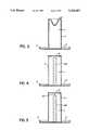
- FIG. 1shows the structure of a uniform diameter helical antenna having an end cap according to the present invention
- FIG. 2is a top view of the end cap of FIG. 1;
- FIG. 3is a sectional view of a further embodiment of an end cap according to the present invention.
- FIG. 4is a sectional view of a further embodiment of the end cap according to the present invention.
- FIG. 5shows a lumped capacitor in accordance with the present invention
- FIG. 6shows a further embodiment of a uniform diameter decreasing pitch helical antenna
- FIG. 7is a plot of gain versus angle of elevation for an antenna according to the present invention.
- FIG. 8is a plot of gain versus angle of elevation for a prior art antenna.
- the antenna 1has a circular ground plane 2 to which is attached a dielectric tube or cylinder 4.
- the dielectric tube 4extends in a direction normal to the plane of the ground plane 2.
- the ground plane 2in turn has an upwardly depending skirt 3 surrounding its perimeter.
- An antenna element or winding 6is wound about the tube or cylinder 4.
- the winding 6extends along the surface of the cylinder from its feedpoint 5 at the ground plane 2 to an end 8 remote thereof.
- the cylinder 4has, at its end remote from the ground plane 2, a flat surface defining a plane parallel to the ground plane 2.
- a conductive cap 10is attached to this surface at the remote end of the cylinder 4 and the free end 8 of the antenna element 6 is electrically connected by an ohmic contact to the conductive cap 10.
- the end of the antenna element 6 at the ground planeis connected to a suitable feed connector 12 which is isolated from the ground plane 2.
- the top view of the capis shown in which the cap 10 comprises a metallic or any suitable conductive material plate.
- the diameter of the plate cap 10corresponds with the diameter of the dielectric cylinder 4.
- the thickness of the cap, on a prototype antenna,was 0.02 inches, however, it was found that the thickness has little impact on performance of the antenna.
- the cap 10 and the ground plane 2form a capacitor C, the capacitance of which may be expressed; ##EQU1##
- ⁇is the permittivity
- xis the spacing between the cap 30 and the ground plane 2 and A is the cross-sectional area of the cap.
- Typical dimensions for the antenna described in the embodiments of FIGS. 1 and 2are as follows:
- the pitch of the windingis tapered from 18 mm at the feedpoint end to 10 mm at the remote end 8. It is also important that the feedpoint 11 of the windings and the free end 8 of the windings are aligned along a plane through the central axis of the cylinder 4.
- the width w 1 of the winding 6may be varied, however, it is normally constant.
- the winding 6may be bonded or etched on to the cylinder 4.
- the helical antenna as shown in FIGS. 1 and 2has a performance indicated by the gain versus elevation plot of FIG. 7.
- FIG. 3a cross sectional view of an alternative embodiment of the conductive cap 10 is shown, along the line A--A of FIG. 2.
- the conductive cap 20 shown in FIG. 3may be termed a sunken cap in that the cap 20 is concavely shaped with an inner central region projecting within the dielectric tube 4.
- the remote end 8 of the antenna elementis electrically connected to the cap 20 as in the embodiment of FIG. 1.
- FIG. 4indicates a conductive post 28 which extends from the ground plane 2.
- the conductive post 28is electrically connected at one end to the ground plane 2 and extends within the dielectric tube 4.
- the free end of the conductive post 28is in proximity to the conductive cap 10 but is not in electrical contact with the cap 10.
- the conductive tube 28may also be used in conjunction with the sunken cap 20 of FIG. 3.
- the conductive post 28 as indicated in FIG. 4is employed in addition to a lumped capacitor element 30 is connected from conductive cap 10 to the free end of conductive post 28.
- a uniform diameter helix antennais indicated as in FIG. 1 however the pitch of the antenna element decreases as the antenna element progresses from the ground plane 2 to the end 8 remote from the ground plane 2.
- a cone shaped conductive cap 60is shown in FIG. 6, to which the free end of the element 8 is ohmically connected.
- skirt 3allows the diameter of the ground plane 2 to be reduced and it also increases the winding to ground plane capacitance while reducing backlobe and sidelobe energy.
Landscapes
- Details Of Aerials (AREA)
- Support Of Aerials (AREA)
Abstract
Description
______________________________________ length of the cylinder 4: l = 21.8 cm diameter of the cylinder 4: d = 5.5 cm wall thickness of the cylinder 4: t = 0.14 cm width of the windings: w.sub.1 = 0.6 cm diamter of ground plane: D = 9.5 cm thickness of ground plane: w = 0.12 cm height of ground plane skirt: H = 2.73 cm ______________________________________
Claims (12)
Applications Claiming Priority (2)
| Application Number | Priority Date | Filing Date | Title |
|---|---|---|---|
| CA002061743ACA2061743C (en) | 1992-02-24 | 1992-02-24 | End loaded helix antenna |
| CA2061743-8 | 1992-02-24 |
Publications (1)
| Publication Number | Publication Date |
|---|---|
| US5329287Atrue US5329287A (en) | 1994-07-12 |
Family
ID=4149317
Family Applications (1)
| Application Number | Title | Priority Date | Filing Date |
|---|---|---|---|
| US07/893,525Expired - LifetimeUS5329287A (en) | 1992-02-24 | 1992-06-04 | End loaded helix antenna |
Country Status (2)
| Country | Link |
|---|---|
| US (1) | US5329287A (en) |
| CA (1) | CA2061743C (en) |
Cited By (49)
| Publication number | Priority date | Publication date | Assignee | Title |
|---|---|---|---|---|
| GB2292257A8 (en)* | 1994-06-22 | Sidney John Branson | Radio frequency antenna | |
| US5572172A (en)* | 1995-08-09 | 1996-11-05 | Qualcomm Incorporated | 180° power divider for a helix antenna |
| US5668559A (en)* | 1993-10-14 | 1997-09-16 | Alcatel Mobile Communication France | Antenna for portable radio devices |
| US5754146A (en)* | 1995-04-26 | 1998-05-19 | Westinghouse Electric Corporation | Helical antenna having a parasitic element and method of using same |
| US5777587A (en)* | 1993-10-12 | 1998-07-07 | Murata Mfg. Co., Ltd. | Surface-mounted antenna |
| US5793338A (en)* | 1995-08-09 | 1998-08-11 | Qualcomm Incorporated | Quadrifilar helix antenna and feed network |
| GB2323476A (en)* | 1997-03-20 | 1998-09-23 | David Ganeshmoorthy | Communication antenna |
| US5828348A (en)* | 1995-09-22 | 1998-10-27 | Qualcomm Incorporated | Dual-band octafilar helix antenna |
| US5854608A (en)* | 1994-08-25 | 1998-12-29 | Symetri Com, Inc. | Helical antenna having a solid dielectric core |
| US5859621A (en)* | 1996-02-23 | 1999-01-12 | Symmetricom, Inc. | Antenna |
| US5910790A (en)* | 1993-12-28 | 1999-06-08 | Nec Corporation | Broad conical-mode helical antenna |
| WO1999039402A1 (en)* | 1998-01-29 | 1999-08-05 | Siemens Aktiengesellschaft | Radio equipment |
| US5945963A (en)* | 1996-01-23 | 1999-08-31 | Symmetricom, Inc. | Dielectrically loaded antenna and a handheld radio communication unit including such an antenna |
| US5963170A (en)* | 1997-05-22 | 1999-10-05 | Lucent Technologies Inc. | Fixed dual frequency band antenna |
| US5990848A (en)* | 1996-02-16 | 1999-11-23 | Lk-Products Oy | Combined structure of a helical antenna and a dielectric plate |
| WO2000046874A1 (en)* | 1999-02-04 | 2000-08-10 | Maxrad, Inc. | Compact wideband antenna |
| US6181298B1 (en) | 1999-08-19 | 2001-01-30 | Ems Technologies Canada, Ltd. | Top-fed quadrafilar helical antenna |
| US6181296B1 (en) | 1998-10-29 | 2001-01-30 | Harris Corporation | Cast core fabrication of helically wound antenna |
| US6243051B1 (en) | 1999-11-05 | 2001-06-05 | Harris Corporation | Dual helical antenna for variable beam width coverage |
| US6300917B1 (en) | 1999-05-27 | 2001-10-09 | Sarantel Limited | Antenna |
| EP1164657A1 (en)* | 2000-06-12 | 2001-12-19 | Filtronic LK Oy | Multiband antenna |
| US6340954B1 (en) | 1997-12-16 | 2002-01-22 | Filtronic Lk Oy | Dual-frequency helix antenna |
| US6369776B1 (en) | 1999-02-08 | 2002-04-09 | Sarantel Limited | Antenna |
| US6373448B1 (en) | 2001-04-13 | 2002-04-16 | Luxul Corporation | Antenna for broadband wireless communications |
| US20020113740A1 (en)* | 1999-06-01 | 2002-08-22 | Nadar Fayyaz | Flat-plate monopole antennae |
| US6501437B1 (en) | 2000-10-17 | 2002-12-31 | Harris Corporation | Three dimensional antenna configured of shaped flex circuit electromagnetically coupled to transmission line feed |
| GB2380328A (en)* | 2001-07-25 | 2003-04-02 | Furuno Electrical Company Ltd | Helical antenna and helical antenna array |
| US6552693B1 (en) | 1998-12-29 | 2003-04-22 | Sarantel Limited | Antenna |
| RU2210844C2 (en)* | 2001-07-03 | 2003-08-20 | 5 Центральный научно-исследовательский испытательный институт Министерства обороны Российской Федерации | Helical antenna |
| US6690336B1 (en) | 1998-06-16 | 2004-02-10 | Symmetricom, Inc. | Antenna |
| US20040257298A1 (en)* | 2003-06-18 | 2004-12-23 | Steve Larouche | Helical antenna |
| US20050088363A1 (en)* | 2002-06-01 | 2005-04-28 | Ovadia Grossman | Multi-frequency band antenna and methods of tuning and manufacture |
| US20050206578A1 (en)* | 2002-04-04 | 2005-09-22 | Byung-Hoon Ryou | Dual band antenna |
| US20060208080A1 (en)* | 2004-11-05 | 2006-09-21 | Goliath Solutions Llc. | Distributed RFID antenna array utilizing circular polarized helical antennas |
| US7307590B1 (en) | 2006-05-19 | 2007-12-11 | The United States Of America As Represented By The Secretary Of The Navy | Wideband traveling wave microstrip antenna |
| US20100176995A1 (en)* | 2009-01-14 | 2010-07-15 | Temic Automotive Of North America, Inc. | Fakra-compliant antenna |
| US9793612B1 (en)* | 2013-07-15 | 2017-10-17 | The United States Of America, As Represented By The Secretary Of The Navy | Reduced profile leaky-wave antenna |
| US9893715B2 (en) | 2013-12-09 | 2018-02-13 | Shure Acquisition Holdings, Inc. | Adaptive self-tunable antenna system and method |
| US9923266B1 (en) | 2013-12-16 | 2018-03-20 | First Rf Corporation | Antenna array with tilted conical helical antennas |
| US10374299B1 (en) | 2015-02-06 | 2019-08-06 | First Rf Corporation | Method for making a radiator structure for a helical antenna |
| US10381737B2 (en)* | 2016-09-15 | 2019-08-13 | Stc.Unm | 3D printed miniaturized quadrifilar helix antenna |
| US10931019B1 (en)* | 2015-12-14 | 2021-02-23 | Lockheed Martin Corporation | Helix antenna |
| US11258181B2 (en)* | 2019-12-20 | 2022-02-22 | Eagle Technology, Llc | Systems and methods for providing a high gain space deployable helix antenna |
| US20220255231A1 (en)* | 2019-07-04 | 2022-08-11 | Poynting Antennas (Pty) Limited | Helical antenna |
| US20230077859A1 (en)* | 2021-09-16 | 2023-03-16 | Eagle Technology, Llc | Communications device with helically wound conductive strip and related antenna devices and methods |
| US12027762B2 (en) | 2022-02-10 | 2024-07-02 | Eagle Technology, Llc | Communications device with helically wound conductive strip with lens and related antenna device and method |
| US12230880B2 (en) | 2022-10-20 | 2025-02-18 | Eagle Technology, Llc | Communications device with rhombus shaped-slot radiating antenna and related antenna device and method |
| US12294147B2 (en) | 2022-10-20 | 2025-05-06 | Eagle Technology, Llc | Communications device with helical slot radiating antenna and related antenna device and method |
| US12438260B1 (en)* | 2024-12-20 | 2025-10-07 | Saltenna Inc. | Surface electromagnetic wave antenna |
Citations (27)
| Publication number | Priority date | Publication date | Assignee | Title |
|---|---|---|---|---|
| CA465508A (en)* | 1950-05-30 | W. Scheldorf Marvel | Single-ended antenna | |
| US2511611A (en)* | 1946-09-17 | 1950-06-13 | Hazeltine Research Inc | Aperiodic directive antenna system |
| CA564984A (en)* | 1958-10-21 | Compagnie Generale De Telegraphie Sans Fil | Omnidirectional aerials | |
| CA759565A (en)* | 1967-05-23 | Electronics Research | Circular-type antenna | |
| CA845308A (en)* | 1970-06-23 | A. Fredriksson Oke | Helical antenna for irradiating an earth formation penetrated by a borehole and method of forming same | |
| US3573840A (en)* | 1967-12-15 | 1971-04-06 | Onera (Off Nat Aerospatiale) | Small bulk helically wound antennae and method for making same |
| US3852756A (en)* | 1974-02-15 | 1974-12-03 | Us Navy | Electrically small resonant antenna with capacitively coupled load |
| US3858220A (en)* | 1973-11-12 | 1974-12-31 | S Arnow | Tunable spiral dipole antenna |
| US4012744A (en)* | 1975-10-20 | 1977-03-15 | Itek Corporation | Helix-loaded spiral antenna |
| US4014028A (en)* | 1975-08-11 | 1977-03-22 | Trw Inc. | Backfire bifilar helical antenna |
| US4051481A (en)* | 1975-01-29 | 1977-09-27 | Abreu Joao Do Espirito Santo | Helical band antenna |
| US4121218A (en)* | 1977-08-03 | 1978-10-17 | Motorola, Inc. | Adjustable antenna arrangement for a portable radio |
| GB1531925A (en)* | 1975-01-29 | 1978-11-15 | Abreu J | Helical antennas |
| US4148030A (en)* | 1977-06-13 | 1979-04-03 | Rca Corporation | Helical antennas |
| US4160979A (en)* | 1976-06-21 | 1979-07-10 | National Research Development Corporation | Helical radio antennae |
| US4161737A (en)* | 1977-10-03 | 1979-07-17 | Albright Eugene A | Helical antenna |
| US4163981A (en)* | 1978-03-27 | 1979-08-07 | Wilson Thomas J | Spring tunable helical whip antenna |
| US4169267A (en)* | 1978-06-19 | 1979-09-25 | The United States Of America As Represented By The Secretary Of The Air Force | Broadband helical antennas |
| US4309707A (en)* | 1979-05-08 | 1982-01-05 | National Research Development Corporation | Radio antennae structures employing helical conductors |
| GB2105521A (en)* | 1981-08-12 | 1983-03-23 | Univ Surrey | Antenna |
| US4494117A (en)* | 1982-07-19 | 1985-01-15 | The United States Of America As Represented By The Secretary Of The Navy | Dual sense, circularly polarized helical antenna |
| CA1186049A (en)* | 1980-07-09 | 1985-04-23 | James F. Corum | Antenna having a closed standing wave path |
| US4580023A (en)* | 1985-03-06 | 1986-04-01 | Amana Refrigeration, Inc. | Microwave oven with circular polarization |
| CA1223346A (en)* | 1984-08-14 | 1987-06-23 | Siltronics Ltd. | Antenna |
| US4772895A (en)* | 1987-06-15 | 1988-09-20 | Motorola, Inc. | Wide-band helical antenna |
| CA1257694A (en)* | 1985-08-05 | 1989-07-18 | Hisamatsu Nakano | Antenna system |
| JPH03128507A (en)* | 1989-10-13 | 1991-05-31 | Sumitomo Electric Ind Ltd | helical antenna |
- 1992
- 1992-02-24CACA002061743Apatent/CA2061743C/ennot_activeExpired - Lifetime
- 1992-06-04USUS07/893,525patent/US5329287A/ennot_activeExpired - Lifetime
Patent Citations (27)
| Publication number | Priority date | Publication date | Assignee | Title |
|---|---|---|---|---|
| CA465508A (en)* | 1950-05-30 | W. Scheldorf Marvel | Single-ended antenna | |
| CA564984A (en)* | 1958-10-21 | Compagnie Generale De Telegraphie Sans Fil | Omnidirectional aerials | |
| CA759565A (en)* | 1967-05-23 | Electronics Research | Circular-type antenna | |
| CA845308A (en)* | 1970-06-23 | A. Fredriksson Oke | Helical antenna for irradiating an earth formation penetrated by a borehole and method of forming same | |
| US2511611A (en)* | 1946-09-17 | 1950-06-13 | Hazeltine Research Inc | Aperiodic directive antenna system |
| US3573840A (en)* | 1967-12-15 | 1971-04-06 | Onera (Off Nat Aerospatiale) | Small bulk helically wound antennae and method for making same |
| US3858220A (en)* | 1973-11-12 | 1974-12-31 | S Arnow | Tunable spiral dipole antenna |
| US3852756A (en)* | 1974-02-15 | 1974-12-03 | Us Navy | Electrically small resonant antenna with capacitively coupled load |
| GB1531925A (en)* | 1975-01-29 | 1978-11-15 | Abreu J | Helical antennas |
| US4051481A (en)* | 1975-01-29 | 1977-09-27 | Abreu Joao Do Espirito Santo | Helical band antenna |
| US4014028A (en)* | 1975-08-11 | 1977-03-22 | Trw Inc. | Backfire bifilar helical antenna |
| US4012744A (en)* | 1975-10-20 | 1977-03-15 | Itek Corporation | Helix-loaded spiral antenna |
| US4160979A (en)* | 1976-06-21 | 1979-07-10 | National Research Development Corporation | Helical radio antennae |
| US4148030A (en)* | 1977-06-13 | 1979-04-03 | Rca Corporation | Helical antennas |
| US4121218A (en)* | 1977-08-03 | 1978-10-17 | Motorola, Inc. | Adjustable antenna arrangement for a portable radio |
| US4161737A (en)* | 1977-10-03 | 1979-07-17 | Albright Eugene A | Helical antenna |
| US4163981A (en)* | 1978-03-27 | 1979-08-07 | Wilson Thomas J | Spring tunable helical whip antenna |
| US4169267A (en)* | 1978-06-19 | 1979-09-25 | The United States Of America As Represented By The Secretary Of The Air Force | Broadband helical antennas |
| US4309707A (en)* | 1979-05-08 | 1982-01-05 | National Research Development Corporation | Radio antennae structures employing helical conductors |
| CA1186049A (en)* | 1980-07-09 | 1985-04-23 | James F. Corum | Antenna having a closed standing wave path |
| GB2105521A (en)* | 1981-08-12 | 1983-03-23 | Univ Surrey | Antenna |
| US4494117A (en)* | 1982-07-19 | 1985-01-15 | The United States Of America As Represented By The Secretary Of The Navy | Dual sense, circularly polarized helical antenna |
| CA1223346A (en)* | 1984-08-14 | 1987-06-23 | Siltronics Ltd. | Antenna |
| US4580023A (en)* | 1985-03-06 | 1986-04-01 | Amana Refrigeration, Inc. | Microwave oven with circular polarization |
| CA1257694A (en)* | 1985-08-05 | 1989-07-18 | Hisamatsu Nakano | Antenna system |
| US4772895A (en)* | 1987-06-15 | 1988-09-20 | Motorola, Inc. | Wide-band helical antenna |
| JPH03128507A (en)* | 1989-10-13 | 1991-05-31 | Sumitomo Electric Ind Ltd | helical antenna |
Non-Patent Citations (1)
| Title |
|---|
| Johnson et al, Antenna Engineering Handbook, Second Edition, 1984, Chapter 13.* |
Cited By (66)
| Publication number | Priority date | Publication date | Assignee | Title |
|---|---|---|---|---|
| US5777587A (en)* | 1993-10-12 | 1998-07-07 | Murata Mfg. Co., Ltd. | Surface-mounted antenna |
| US5668559A (en)* | 1993-10-14 | 1997-09-16 | Alcatel Mobile Communication France | Antenna for portable radio devices |
| US5910790A (en)* | 1993-12-28 | 1999-06-08 | Nec Corporation | Broad conical-mode helical antenna |
| GB2292257A8 (en)* | 1994-06-22 | Sidney John Branson | Radio frequency antenna | |
| GB2292257A (en)* | 1994-06-22 | 1996-02-14 | Sidney John Branson | Radio frequency antenna |
| GB2292257B (en)* | 1994-06-22 | 1999-04-07 | Sidney John Branson | An antenna |
| US5854608A (en)* | 1994-08-25 | 1998-12-29 | Symetri Com, Inc. | Helical antenna having a solid dielectric core |
| US6181297B1 (en) | 1994-08-25 | 2001-01-30 | Symmetricom, Inc. | Antenna |
| US5754146A (en)* | 1995-04-26 | 1998-05-19 | Westinghouse Electric Corporation | Helical antenna having a parasitic element and method of using same |
| US5793338A (en)* | 1995-08-09 | 1998-08-11 | Qualcomm Incorporated | Quadrifilar helix antenna and feed network |
| US5572172A (en)* | 1995-08-09 | 1996-11-05 | Qualcomm Incorporated | 180° power divider for a helix antenna |
| US5828348A (en)* | 1995-09-22 | 1998-10-27 | Qualcomm Incorporated | Dual-band octafilar helix antenna |
| US5945963A (en)* | 1996-01-23 | 1999-08-31 | Symmetricom, Inc. | Dielectrically loaded antenna and a handheld radio communication unit including such an antenna |
| US5990848A (en)* | 1996-02-16 | 1999-11-23 | Lk-Products Oy | Combined structure of a helical antenna and a dielectric plate |
| US5859621A (en)* | 1996-02-23 | 1999-01-12 | Symmetricom, Inc. | Antenna |
| GB2323476A (en)* | 1997-03-20 | 1998-09-23 | David Ganeshmoorthy | Communication antenna |
| GB2323476B (en)* | 1997-03-20 | 2002-01-16 | David Ganeshmoorthy | Communication antenna and equipment |
| US5963170A (en)* | 1997-05-22 | 1999-10-05 | Lucent Technologies Inc. | Fixed dual frequency band antenna |
| US6340954B1 (en) | 1997-12-16 | 2002-01-22 | Filtronic Lk Oy | Dual-frequency helix antenna |
| US6456259B1 (en) | 1998-01-29 | 2002-09-24 | Siemens Aktiengesellschaft | Radio equipment |
| WO1999039402A1 (en)* | 1998-01-29 | 1999-08-05 | Siemens Aktiengesellschaft | Radio equipment |
| US6690336B1 (en) | 1998-06-16 | 2004-02-10 | Symmetricom, Inc. | Antenna |
| US6181296B1 (en) | 1998-10-29 | 2001-01-30 | Harris Corporation | Cast core fabrication of helically wound antenna |
| US6552693B1 (en) | 1998-12-29 | 2003-04-22 | Sarantel Limited | Antenna |
| WO2000046874A1 (en)* | 1999-02-04 | 2000-08-10 | Maxrad, Inc. | Compact wideband antenna |
| US6369776B1 (en) | 1999-02-08 | 2002-04-09 | Sarantel Limited | Antenna |
| US6300917B1 (en) | 1999-05-27 | 2001-10-09 | Sarantel Limited | Antenna |
| US20020113740A1 (en)* | 1999-06-01 | 2002-08-22 | Nadar Fayyaz | Flat-plate monopole antennae |
| US6181298B1 (en) | 1999-08-19 | 2001-01-30 | Ems Technologies Canada, Ltd. | Top-fed quadrafilar helical antenna |
| US6243051B1 (en) | 1999-11-05 | 2001-06-05 | Harris Corporation | Dual helical antenna for variable beam width coverage |
| EP1164657A1 (en)* | 2000-06-12 | 2001-12-19 | Filtronic LK Oy | Multiband antenna |
| US6473056B2 (en) | 2000-06-12 | 2002-10-29 | Filtronic Lk Oy | Multiband antenna |
| US6501437B1 (en) | 2000-10-17 | 2002-12-31 | Harris Corporation | Three dimensional antenna configured of shaped flex circuit electromagnetically coupled to transmission line feed |
| US6373448B1 (en) | 2001-04-13 | 2002-04-16 | Luxul Corporation | Antenna for broadband wireless communications |
| RU2210844C2 (en)* | 2001-07-03 | 2003-08-20 | 5 Центральный научно-исследовательский испытательный институт Министерства обороны Российской Федерации | Helical antenna |
| GB2380328B (en)* | 2001-07-25 | 2005-10-19 | Furuno Electric Co | Helical antenna and helical antenna array |
| US6816126B2 (en) | 2001-07-25 | 2004-11-09 | Furuno Electric Company Ltd. | Helical antenna and helical antenna array |
| GB2380328A (en)* | 2001-07-25 | 2003-04-02 | Furuno Electrical Company Ltd | Helical antenna and helical antenna array |
| US20050206578A1 (en)* | 2002-04-04 | 2005-09-22 | Byung-Hoon Ryou | Dual band antenna |
| US20050088363A1 (en)* | 2002-06-01 | 2005-04-28 | Ovadia Grossman | Multi-frequency band antenna and methods of tuning and manufacture |
| US7038636B2 (en) | 2003-06-18 | 2006-05-02 | Ems Technologies Cawada, Ltd. | Helical antenna |
| US20040257298A1 (en)* | 2003-06-18 | 2004-12-23 | Steve Larouche | Helical antenna |
| US20060208080A1 (en)* | 2004-11-05 | 2006-09-21 | Goliath Solutions Llc. | Distributed RFID antenna array utilizing circular polarized helical antennas |
| US20080258876A1 (en)* | 2004-11-05 | 2008-10-23 | Overhultz Gary L | Distributed Antenna Array With Centralized Data Hub For Determining Presence And Location Of RF Tags |
| US7614556B2 (en)* | 2004-11-05 | 2009-11-10 | Goliath Solutions, Llc | Distributed RFID antenna array utilizing circular polarized helical antennas |
| US8070065B2 (en) | 2004-11-05 | 2011-12-06 | Goliath Solutions, Llc | Distributed antenna array with centralized data hub for determining presence and location of RF tags |
| US7307590B1 (en) | 2006-05-19 | 2007-12-11 | The United States Of America As Represented By The Secretary Of The Navy | Wideband traveling wave microstrip antenna |
| US20100176995A1 (en)* | 2009-01-14 | 2010-07-15 | Temic Automotive Of North America, Inc. | Fakra-compliant antenna |
| US8436775B2 (en)* | 2009-01-14 | 2013-05-07 | Continental Automotive Systems, Inc. | Fakra-compliant antenna |
| US9793612B1 (en)* | 2013-07-15 | 2017-10-17 | The United States Of America, As Represented By The Secretary Of The Navy | Reduced profile leaky-wave antenna |
| US11469740B2 (en) | 2013-12-09 | 2022-10-11 | Shure Acquisition Holdings, Inc. | Adaptive self-tunable antenna system and method |
| US10348272B2 (en) | 2013-12-09 | 2019-07-09 | Shure Acquisition Holdings, Inc. | Adaptive self-tunable antenna system and method |
| US9893715B2 (en) | 2013-12-09 | 2018-02-13 | Shure Acquisition Holdings, Inc. | Adaptive self-tunable antenna system and method |
| US9923266B1 (en) | 2013-12-16 | 2018-03-20 | First Rf Corporation | Antenna array with tilted conical helical antennas |
| US10374299B1 (en) | 2015-02-06 | 2019-08-06 | First Rf Corporation | Method for making a radiator structure for a helical antenna |
| US10931019B1 (en)* | 2015-12-14 | 2021-02-23 | Lockheed Martin Corporation | Helix antenna |
| US10381737B2 (en)* | 2016-09-15 | 2019-08-13 | Stc.Unm | 3D printed miniaturized quadrifilar helix antenna |
| US20220255231A1 (en)* | 2019-07-04 | 2022-08-11 | Poynting Antennas (Pty) Limited | Helical antenna |
| US12068537B2 (en)* | 2019-07-04 | 2024-08-20 | Poynting Antennas (Pty) Limited | Helical antenna |
| US11258181B2 (en)* | 2019-12-20 | 2022-02-22 | Eagle Technology, Llc | Systems and methods for providing a high gain space deployable helix antenna |
| US20230077859A1 (en)* | 2021-09-16 | 2023-03-16 | Eagle Technology, Llc | Communications device with helically wound conductive strip and related antenna devices and methods |
| US11682841B2 (en)* | 2021-09-16 | 2023-06-20 | Eagle Technology, Llc | Communications device with helically wound conductive strip and related antenna devices and methods |
| US12027762B2 (en) | 2022-02-10 | 2024-07-02 | Eagle Technology, Llc | Communications device with helically wound conductive strip with lens and related antenna device and method |
| US12230880B2 (en) | 2022-10-20 | 2025-02-18 | Eagle Technology, Llc | Communications device with rhombus shaped-slot radiating antenna and related antenna device and method |
| US12294147B2 (en) | 2022-10-20 | 2025-05-06 | Eagle Technology, Llc | Communications device with helical slot radiating antenna and related antenna device and method |
| US12438260B1 (en)* | 2024-12-20 | 2025-10-07 | Saltenna Inc. | Surface electromagnetic wave antenna |
Also Published As
| Publication number | Publication date |
|---|---|
| CA2061743A1 (en) | 1993-08-25 |
| CA2061743C (en) | 1996-05-14 |
Similar Documents
| Publication | Publication Date | Title |
|---|---|---|
| US5329287A (en) | End loaded helix antenna | |
| US5677699A (en) | Helical microstrip antenna with impedance taper | |
| US4697192A (en) | Two arm planar/conical/helix antenna | |
| US7286095B2 (en) | Inverted feed discone antenna and related methods | |
| US6693600B1 (en) | Ultra-broadband antenna achieved by combining a monocone with other antennas | |
| WO1987000351A1 (en) | Axial multipole mobile antenna | |
| US6891515B1 (en) | Multiband antenna | |
| US6486849B2 (en) | Small L-band antenna | |
| US5754146A (en) | Helical antenna having a parasitic element and method of using same | |
| EP3152798B1 (en) | Conical monopole antenna | |
| US4301457A (en) | Antenna employing curved parasitic end-fire directors | |
| US3618114A (en) | Conical logarithmic-spiral antenna | |
| US11682841B2 (en) | Communications device with helically wound conductive strip and related antenna devices and methods | |
| EP2489097B1 (en) | Increased gain in an array antenna through optimal suspension of piece-wise linear conductors | |
| US3438042A (en) | Center fed vertical dipole antenna | |
| EP0394960A1 (en) | A microstrip antenna | |
| US4342037A (en) | Decoupling means for monopole antennas and the like | |
| GB2196483A (en) | Antenna | |
| US3071771A (en) | Suppressed-radiation antenna | |
| CN209843939U (en) | UHF frequency range helical antenna | |
| CN216648604U (en) | Cylindrical spiral high-power transmitting antenna with cone angle bottom cavity | |
| US12230880B2 (en) | Communications device with rhombus shaped-slot radiating antenna and related antenna device and method | |
| US12294147B2 (en) | Communications device with helical slot radiating antenna and related antenna device and method | |
| US12027762B2 (en) | Communications device with helically wound conductive strip with lens and related antenna device and method | |
| US20250192443A1 (en) | Communications device with rhombus shaped-slot radiating antenna and related antenna device and method |
Legal Events
| Date | Code | Title | Description |
|---|---|---|---|
| AS | Assignment | Owner name:CAL CORPORATION, CANADA Free format text:ASSIGNMENT OF ASSIGNORS INTEREST.;ASSIGNOR:STRICKLAND, PETER C.;REEL/FRAME:006180/0865 Effective date:19920218 | |
| STCF | Information on status: patent grant | Free format text:PATENTED CASE | |
| FEPP | Fee payment procedure | Free format text:PAYOR NUMBER ASSIGNED (ORIGINAL EVENT CODE: ASPN); ENTITY STATUS OF PATENT OWNER: SMALL ENTITY | |
| FPAY | Fee payment | Year of fee payment:4 | |
| AS | Assignment | Owner name:EMS TECHNOLOGIES CANADA, LTD., CANADA Free format text:CHANGE OF NAME;ASSIGNOR:CAL CORPORATION;REEL/FRAME:010070/0561 Effective date:19990128 | |
| FPAY | Fee payment | Year of fee payment:8 | |
| AS | Assignment | Owner name:BANK OF AMERICA, NATIONAL ASSOCIATION, CANADA Free format text:SECURITY INTEREST;ASSIGNOR:EMS TECHNOLOGIES CANADA, LTD.;REEL/FRAME:015778/0208 Effective date:20041210 | |
| FPAY | Fee payment | Year of fee payment:12 | |
| AS | Assignment | Owner name:EMS TECHNOLOGIES CANADA, LTD., CANADA Free format text:TERMINATION OF SECURITY INTEREST IN PATENTS;ASSIGNOR:BANK OF AMERICA, NATIONAL ASSOCIATION (CANADA BRANCH);REEL/FRAME:020617/0014 Effective date:20080229 Owner name:BANK OF AMERICA, NATIONAL ASSOCIATION, ACTING THRO Free format text:NOTICE OF GRANT OF SECURITY INTEREST;ASSIGNOR:EMS TECHNOLOGIES CANADA, LTD.;REEL/FRAME:020617/0092 Effective date:20080229 | |
| AS | Assignment | Owner name:EMS TECHNOLOGIES CANADA, LTD., CANADA Free format text:RELEASE OF SECURITY INTEREST IN PATENTS;ASSIGNOR:BANK OF AMERICA, NATIONAL ASSOCIATION, ACTING THROUGH ITS CANADA BRANCH, AS CANADIAN ADMINISTRATIVE AGENT;REEL/FRAME:026804/0425 Effective date:20110822 |