US5328517A - Method and system for removing a coating from a substrate using radiant energy and a particle stream - Google Patents
Method and system for removing a coating from a substrate using radiant energy and a particle streamDownload PDFInfo
- Publication number
- US5328517A US5328517AUS07/813,872US81387291AUS5328517AUS 5328517 AUS5328517 AUS 5328517AUS 81387291 AUS81387291 AUS 81387291AUS 5328517 AUS5328517 AUS 5328517A
- Authority
- US
- United States
- Prior art keywords
- substrate
- particle stream
- impinging
- irradiating
- scan speed
- Prior art date
- Legal status (The legal status is an assumption and is not a legal conclusion. Google has not performed a legal analysis and makes no representation as to the accuracy of the status listed.)
- Expired - Fee Related
Links
Images


Classifications
- B—PERFORMING OPERATIONS; TRANSPORTING
- B24—GRINDING; POLISHING
- B24C—ABRASIVE OR RELATED BLASTING WITH PARTICULATE MATERIAL
- B24C1/00—Methods for use of abrasive blasting for producing particular effects; Use of auxiliary equipment in connection with such methods
- B24C1/08—Methods for use of abrasive blasting for producing particular effects; Use of auxiliary equipment in connection with such methods for polishing surfaces, e.g. smoothing a surface by making use of liquid-borne abrasives
- B24C1/086—Descaling; Removing coating films
- B—PERFORMING OPERATIONS; TRANSPORTING
- B08—CLEANING
- B08B—CLEANING IN GENERAL; PREVENTION OF FOULING IN GENERAL
- B08B7/00—Cleaning by methods not provided for in a single other subclass or a single group in this subclass
- B08B7/0035—Cleaning by methods not provided for in a single other subclass or a single group in this subclass by radiant energy, e.g. UV, laser, light beam or the like
- B—PERFORMING OPERATIONS; TRANSPORTING
- B23—MACHINE TOOLS; METAL-WORKING NOT OTHERWISE PROVIDED FOR
- B23K—SOLDERING OR UNSOLDERING; WELDING; CLADDING OR PLATING BY SOLDERING OR WELDING; CUTTING BY APPLYING HEAT LOCALLY, e.g. FLAME CUTTING; WORKING BY LASER BEAM
- B23K26/00—Working by laser beam, e.g. welding, cutting or boring
- B23K26/14—Working by laser beam, e.g. welding, cutting or boring using a fluid stream, e.g. a jet of gas, in conjunction with the laser beam; Nozzles therefor
- B23K26/144—Working by laser beam, e.g. welding, cutting or boring using a fluid stream, e.g. a jet of gas, in conjunction with the laser beam; Nozzles therefor the fluid stream containing particles, e.g. powder
- B—PERFORMING OPERATIONS; TRANSPORTING
- B24—GRINDING; POLISHING
- B24C—ABRASIVE OR RELATED BLASTING WITH PARTICULATE MATERIAL
- B24C1/00—Methods for use of abrasive blasting for producing particular effects; Use of auxiliary equipment in connection with such methods
- B24C1/003—Methods for use of abrasive blasting for producing particular effects; Use of auxiliary equipment in connection with such methods using material which dissolves or changes phase after the treatment, e.g. ice, CO2
- B—PERFORMING OPERATIONS; TRANSPORTING
- B44—DECORATIVE ARTS
- B44D—PAINTING OR ARTISTIC DRAWING, NOT OTHERWISE PROVIDED FOR; PRESERVING PAINTINGS; SURFACE TREATMENT TO OBTAIN SPECIAL ARTISTIC SURFACE EFFECTS OR FINISHES
- B44D3/00—Accessories or implements for use in connection with painting or artistic drawing, not otherwise provided for; Methods or devices for colour determination, selection, or synthesis, e.g. use of colour tables
- B44D3/16—Implements or apparatus for removing dry paint from surfaces, e.g. by scraping, by burning
- B44D3/166—Implements or apparatus for removing dry paint from surfaces, e.g. by scraping, by burning by heating, e.g. by burning
Definitions
- the present inventionrelates to a process and system for removing a coating from a substrate, and more particularly to a material removal process and system that uses pulsed light to pyrolyze a coating on a substrate and a particle stream to impinge and remove the pyrolyzed coating.
- Coatingsplay an important-role in today's manufactured products based society. Coatings provide immunity to corrosion, thermal insulation, shielding, enhanced appearance, as well as aid in identification. Paints and other types of protective coatings are purposely designed to adhere to the substrate to which they are applied and resist removal. Thus, the removal of paints and other coatings from a substrate is usually very difficult.
- PMBparticle medium blast
- PMB methodssufficiently energetic to remove hardened coatings, such as paint, by themselves may damage delicate surfaces such as found on aircraft and automobiles if they are not carefully managed. For example, if the impinging particles dwell too long at one location, the impinged surface may become pitted or stress hardened. This is especially important with regard to the surfaces of aircraft since pitting or stress hardening may change the mechanical properties of the surface material.
- High-energy PMB methodsmay also deform the surface of the substrate sufficiently to mask fatigue cracks and other anomalies which, if undetected and uncorrected, could lead to catastrophic failure of the substrate. PMB may also damage putty joints often found on aircraft between surface plates. Moreover, these processes generate a large amount of particulate waste requiring costly disposal. This waste is contaminated by toxic constituents of the coating, increasing the difficulty and expense of its disposal.
- Another methodinvolves the application of chemical agents to painted surfaces in order to chemically break down the layers of paint, thereby stripping the paint away from the surface to be exposed.
- agentsmay pose a risk to human health, are usually toxic, and are often not biodegradable. Overall, these types of agents are difficult and costly to dispose of because they present serious environmental problems. Government regulations are increasingly restrictive of the use of such agents.
- Still other methodsinvolve the application of radiant energy to the coating.
- One such systemuses a flashlamp pumped laser and video frame grabber in a video controlled paint removal system in which paint is stripped from a surface using the output of the laser to ablate the paint while a video camera converts images of the surface being stripped into electronic data signals. The data signals are used to control the laser output.
- a processorcompares the data signals with parameters stored in a memory to determine whether sufficient paint has been removed from the surface being stripped. If an insufficient amount of paint has been removed, then the laser continues to irradiate the surface. If the surface has been adequately stripped, the processor directs the laser to ablate another area.
- a significant problem with the video controlled paint removal systemis that the amount of data which is generated and which must be processed is enormous, making real time control extremely difficult.
- a laser powerful enough to vaporize paintrequires high power due, in part, to laser pumping inefficiencies. Employment of such a powerful laser requires a large capital investment in order to provide space to operate the laser, as well as laser stops to prevent the laser beam from inadvertently escaping the work area and even the building where it is being used. Such a laser poses a serious danger to humans, who must be kept out of the area where the laser operates. Another problem with the use of lasers is the occurrence of localized "hot spots" which can damage or destroy the substrate.
- Pulsed lightfor example from flashlamps, has also been used to ablate coatings from their substrates.
- a problem with ablating solely with radiant energyis the risk of heat damage to the substrate.
- ablationcan result in flame and smoke which can reduce the efficiency of or damage the equipment and which may pose a hazard for personnel.
- these processestypically leave a non-water soluble carbonized residue that must be removed in a labor-intensive process.
- composite structures manufactured, for example, of carbon epoxy or other reinforced plastic materialsis becoming increasingly common.
- Many aircraft and automobilesextensively employ reinforced composite materials, including carbon epoxy materials, for surface structures.
- Such structuresare painted for a variety of reasons including aesthetics, identification, and camouflage.
- Such painted surfacesdeteriorate under the action of weather and the mechanical forces to which they are subjected, thus requiring removal and replacement.
- This inventionprovides a method of removing material from a structure having at least one layer of material formed on a substrate.
- the methodcomprises irradiating the material sufficiently to weaken the material and its adhesion to the substrate, and impinging the weakened material to remove it from the substrate. This weakening results from the breaking or weakening of the chemical bonds in the material, and between the material and the substrate.
- One embodiment of the inventionprovides a method for removing material from a structure, comprising the steps of: irradiating a target area on the structure with radiant energy sufficient to pyrolyze the material without substantially ablating the material; and impinging the target area with a particle stream to remove the pyrolyzed material from the structure.
- the methodis implemented by a system comprising a housing having a window; a radiant energy source mounted in the housing for irradiating the target area on the structure with the radiant energy; and a nozzle mounted to the exterior of the housing for directing the stream of particles generally at the target area.
- Another embodiment of the inventionprovides a method and system for removing material from a substrate that employs a photodetecting system which detects the optical character of the surface of the structure. Feedback generated by the photodetecting system is analyzed by a digital data processor which generates output signals that control the scan speed of the radiant energy source and particle stream over the structure.
- a method by which the second embodiment may be implementedincludes the steps of: irradiating a target area on the structure with radiant energy sufficient to pyrolyze the material without substantially ablating said material; impinging the pyrolyzed material with a particle stream to remove the pyrolyzed material from said substrate; scanning the surface of the structure with the radiant energy and the particle stream along a predetermined path at a scan speed; detecting the optical character of the surface of the structure along the path; updating the scan speed based upon the detected optical character; and repeating steps of the process if the radiant energy and said particle stream have not scanned the entirety of the predetermined path.
- a significant advantage of the inventionis that it provides a coating removal technique that is gentle and benign to underlying substrates.
- the radiant energyis preferably pulsed light that heats the coating, causing it to pyrolyze. Pyrolysis reduces the cohesion of the material to itself and its adhesion to the underlying substrate.
- the pyrolyzed coatingis removed using a relatively low-power particle stream. Because the pyrolyzed material does not adhere well to the surface of the substrate, a relatively low-energy particle stream is able to dislodge the pyrolyzed coating from the substrate.
- the resulting combination processcan be more benign as well as more efficient than either a more energetic pulsed light or particle jet based process alone.
- the inventionis ideally suited for removing coatings from any substrate, including delicate, thin, or composite substrates. Another advantage of the invention is that it may be economically employed to remove coatings from large areas under the control of a data processor.
- FIG. 1is a schematic diagram of an a first embodiment of a system embodying various features of the present invention for removing a coating from a substrate by pyrolyzing and blasting the coating from the surface of the substrate.
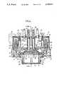
- FIG. 2is a vertical cross-sectional view of the housing in which the light source and reflector are mounted.
- FIG. 3is a vertical cross-sectional view of the housing taken along the plane of line 3--3 in FIG. 2.
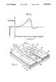
- FIG. 4is a graph showing a qualitative temperature profile along a path on the structure resulting from irradiating a target area of the structure with the light source and cooling the target area with a particle stream.
- FIG. 5illustrates the target area of the light source and the footprint of the particle stream on the surface of the structure.
- FIG. 6is a perspective view of the nozzle through which the particle stream is ejected.
- FIG. 7is a block diagram of a second embodiment of a system embodying various features of the present invention which employs a photodetecting circuit that generates feedback used to control the removal of the coating.
- FIG. 8is a diagram of an apparatus embodying various features of the present invention for removing a coating from a substrate by pyrolyzing and blasting the coating from the surface of the substrate which includes optical feed back to control the coating removal process.
- FIG. 9is a block diagram of the photodetecting circuit.
- FIG. 10is a graph showing the functional relation between the scan speed and the output of the photodetecting circuit.
- FIGS. 11A and 11Bare a flow chart illustrating an example of one process by which the second embodiment may be implemented.
- FIG. 12is a schematic diagram of a third embodiment of a system embodying various features of the present invention.
- FIG. 13is a graph of acoustic energy generated in the vicinity of the application of radiant energy, versus flashlamp fluency for a 464 ⁇ sec FWHM flashlamp pulse.
- the first embodiment of the present inventionprovides a relatively gentle process and system for removing coatings from a substrate by irradiating the coating with pulsed radiant energy, such as light, sufficient to pyrolyze the coating to weaken the chemical bonds both within the coating and between the coating and the substrate, and then impinging the weakened coating with a low-energy particle stream to physically dislodge the coating from the substrate. Pyrolysis weakens and breaks cohesive bonds in the material and adhesive bonds between the coating and the substrate.
- the present inventionis particularly suited for removing paint from the surfaces of fragile substrates such as plastic, alclad aluminum, aluminum alloys, and composite materials. This embodiment is expected to find wide use in the paint removal industry.
- the system 10includes a housing 12 in which is mounted a radiant energy source such as optical energy source 14 and reflector 16 such that optical energy generated by the source 14 is directed and/or reflected off of the reflector 16 through a window 20 so as to irradiate a target area 91 (see FIG. 5) on the surface of a structure 22.
- the structure 22is comprised of a substrate 28 on which is formed, by way of example, layers 26 and 24. Although structure 22 may include any number of layers, for purposes of illustration the structure 22 is described herein as having two layers formed on the substrate.
- the optical energy source 14 and reflector 16are preferably cooled by deionized water provided from a water supply (not shown) to the interior 51 of the housing 12 through an inlet tube 44 and returned through an outlet tube 46.
- the optical energy source 14may be a broadband flashlamp.
- a flashlamp, or flashtubeis a gas-filled device which converts electrical energy to optical energy by passing current through a plasma typically contained in a transparent tube through which the optical energy is transmitted.
- a broadband flashlampgenerates optical energy having wavelengths which may range from 170-5000 nm.
- a broadband flashlampprovides electromagnetic energy over a broad spectrum, increasing the likelihood of absorption by the various components of the coating.
- a flashlampoffers the further advantage of being readily adaptable for irradiating relatively large areas.
- the housing 12is supported by manipulator 19 which may be controlled to move housing 12 over the surface of structure 22 at a standoff distance, d, in order to irradiate and scan the structure with optical energy generated by optical energy source 14.
- the standoff distance drepresents the perpendicular distance between window 20 and the top surface of structure 22.
- the manipulator 19,may for example, be a CIMROC 4000 Robot Controller manufactured by CIMCORP Precision systems, Inc., Shoreview, Minn.
- the intensity of light energy incident on structure 22must be sufficient so that the light absorbed by the layers 24 and 26 heats these layers sufficiently to weaken and/or break the chemical bonds in the molecules of the material comprising the layers 24 and 26 in a process referred to as pyrolysis.
- the breakdown of the materialweakens the adhesion of the material to itself and to the substrate, facilitating the removal of the material.
- the depth of heating resulting from a single light pulseis a function of the intensity and pulse width of the optical energy source 14, the stand-off distance of the optical energy source, the scan rate of the optical energy source across the surface of the structure, the thickness of the layers, and the thermal characteristics of the materials comprising the layers.
- a major advantage of the inventionis that the process can be controlled, by controlling the depth of heating as explained more fully herein, so that layers 24 and 26 may be removed from the surface of substrate 28 without subjecting the substrate to excessive, potentially damaging, heat build-up. Damage would be evidenced by permanent changes in the shape or in the mechanical properties of the substrate, such as the modulus of elasticity, shear strength, and tensile strength. Such changes in the shape or in the mechanical properties of the substrate are undesirable.
- a particle stream 30is ejected from nozzle 32 and directed to impinge the pyrolyzed portions of layers 24 and 26 so as to dislodge the pyrolyzed portions 42 of the layers 24 and 26 from the substrate 28.
- the particle stream 30is provided to nozzle 32 via duct 34 from a particle supply, not shown.
- the particle stream 30may be composed of gases, liquids, or solids, as for example, inert gas, dry air, water, water droplets, carbon dioxide gas, carbon dioxide pellets, walnut shells, and the like, or any combination of gas, liquid, or solids entrained in gas or liquid or solid.
- the particlescomprise particles of a frozen gas, such as CO 2 or Ar.
- particle stream 30it may be desirable to heat any such gas to prevent any moisture from the surrounding atmosphere from condensing on the surface of structure 22 in the area impinged by the particle stream if the temperature of the surface would otherwise drop below the dew point. It may also be desirable for particle stream 30 to have a temperature well below ambient temperature in order to control the temperature of the pyrolyzed material on the substrate 28, so that the substrate 28 does not sustain heat damage, yet the material remains in a pyrolyzed state.
- a low kinetic energy particle stream of frozen carbon dioxide pellets entrained in a dry, high pressure transport gashave been found particularly suitable for removing paint and primer from aluminum and organic composite surfaces of aircraft.
- Frozen CO 2 particlesare particularly desirable because they impart kinetic energy to the coating, and they also function to keep the substrate cool, so that it is not damaged by the high temperatures generated by the flash lamp. It is believed that maintaining a temperature differential between the substrate and the coating enhances removal.
- the CO 2also helps to cool and clean the window of the flashlamp or other radiant energy source. It is believed that the frozen CO 2 sublimes upon or shortly after impact with the coating and, therefore, is instantly separated from the material that has been removed from the substrate. Thus, the volume of waste that must be disposed of is greatly reduced over other particle blasting systems.
- the resulting CO 2 gascreates a fire and explosion resistant environment around the removal site, and also suppresses deleterious smoke and soot.
- An example of a suitable device for providing the frozen CO 2 particlesis the Model 65-200 unit available from Cold Jet, Inc., Cincinnati, Ohio. The device is capable of providing frozen CO 2 in particles with diameters ranging from 0.080 in. to 0.140 in., with transport gas pressures of from 50 psig to 350 psig, and mass flow rates from 0 to 1500 lbs/hr.
- Suitable equipment for creating and delivering particle streamsis disclosed in U.S. Pat. Nos. 4,947,592, 4,744,181, 4,843,770, 5,056,805, 5,018,667, and 5,063,015, incorporated herein by reference.
- the nozzle 32is mounted to the housing 12 so that as the housing is translated across the structure 22, the optical energy source 14 scans different target areas on structure 22, with the nozzle 32 following.
- the material on the structure 22is subjected to a continuous process whereby the optical energy source 14 scans the structure 22 to irradiate and pyrolyze selected target areas on the structure while the particle stream 30 removes the pyrolyzed material.
- Area 90includes the focus or "target" area 91, having a width W L that is subjected to the more intense irradiation and is surrounded by penumbra area 92 which is subjected to less intense irradiation.
- the area 91has a "leading" edge 43 and a "trailing" edge 110.
- the area 91is shown to be substantially rectangular, however, the shape of area 91 depends on the particular configuration of reflector 16, which may be selected to suit the requirements of a specific application.
- the particle stream 30(not shown in FIG. 5) impinges and scans the surface 98 in the direction of arrow 21 with a pattern or footprint 93 that is determined by the size and shape of the outlet 33 of nozzle 32, shown in FIG. 6.
- the footprint 93having a leading edge 95 and a trailing edge 94, overlaps a portion of the target area 91 such that the leading edge 95 of the footprint 93 is just slightly ahead of the trailing edge 110 of the target area 91 in order to assure that particle stream 30 impinges pyrolyzed portions of the layers 24 and 26.
- the target area 91 of the optical energy source 14 and the footprint 93 of the particle stream 30may slightly overlap.
- the particle streamsimultaneously impinges at least a portion of the target area while it is being irradiated with optical energy.
- the leading edge 95 of the footprint 93 of the particle stream 30may also impinge behind the pyrolyzed portions of the layers 24 and 26, with no overlap, provided that the portion impinged by the particle stream 30 is in a pyrolyzed state.
- the target areais first irradiated by optical energy source 14, and then momentarily later, is impinged by particle stream 30.
- the effect of scanning the surface 98 of the structure 22 with optical energy source 14 and particle stream 30results in removal of segments of layers 24 and 26 to expose some of the surface 97 of the substrate 28.
- the particle stream 30removes the coating in layers of a depth generally corresponding to depth of heating caused by the high intensity pulsed light.
- the shape of the footprint 93(FIG. 5) is determined by the shape of outlet 33 of nozzle 32 and the angle ⁇ , between the flow axis of nozzle 32 and the surface 98 of the structure 22.
- the angle of incidence ⁇is selected to maximize the removal effect of the particles for a specific application, while minimizing the impact of the particles on the substrate. Moreover at this angle CO 2 rebounding from the structure tends to cool and clean the window 20 of the radiant energy source 14, enhancing its efficiency and extending its service life.
- the shape of outlet 33may be an elongated rectangle (as shown in FIG. 5), or oval. If the particle stream 30 is comprised of carbon dioxide pellets entrained in dry air, the thickness 33A of outlet 33 must be sufficient for the pellets to flow through the outlet 33 so that the outlet does not clog from any condensing moisture or from the pellets themselves.
- a vacuum system 37draws the gases, spent particles, and dislodged pyrolyzed portions of the layers 26 and 24 away from the footprint through nozzle 36.
- Such vacuum systemsare well known in the art.
- the amount of radiant energy appliedis preferably not great enough to ablate substantial amounts of layers 24 and 26 in the target area.
- Ablationis a process in which so much energy is applied to the material that in addition to breaking chemical bonds in the material, which forms smaller molecules, the resulting smaller molecules are quickly and violently vaporized from the surface.
- ablationis not the preferred mode of removal.
- the radiant energyis therefore preferably applied to substantially pyrolyze the material without substantial ablation. Substantial ablation occurs when the majority of the material to be removed is removed from the substrate in an ablation process.
- the intensity of incident light energywill generally be in the range of about 1 to 30 joules/cm 2 at a FWHM pulse of about 1500 microseconds.
- Control of the amount of radiant energy applied to the surface 98 of the structure 22is easily effected primarily by employing an optical energy source 14 having a suitable output, and secondarily by establishing a suitable standoff distance between the surface of the structure and the source of radiant energy and an appropriate scan rate.
- FIG. 2is a vertical transverse cross-sectional view of a system for implementing the method of the first embodiment.
- the housing 12comprises upper housing member 50 attached to lower housing member 52 with fasteners 54 that extend through the upper housing member 50 and engage stanchions 57 on the lower housing member 52.
- a sealing gasket 56is disposed between the upper and lower housing members 50 and 52 to form a sealed chamber 51 in the upper housing member 50.
- the housing 12is preferably made from black, hard anodized aluminum.
- the lower housing member 52has depending vertical walls 63.
- a flashlamp 48 sealed inside a fused quartz water jacket 49is mounted between opposing walls 63 on the lower housing member. Electrical connectors 67a and 67b at the ends of the flashlamp 48 extend through apertures 62 in the walls 63.
- the flashlamp 48is secured by compression fittings 58 that fit over the electrical connectors 67a and 67b, and are secured to the walls 63 by fasteners (not shown).
- the compression fittings 58have "O"-rings 59 for making a water tight seal between the ends of the flashlamp 48 and the walls 63.
- the reflector 16is disposed around the flashlamp 48.
- the reflector 16preferably has an elliptical cross-section, as best shown in FIG. 3, in which case the longitudinal axis of the flashlamp coincides with one of the foci of the reflector 16.
- the ellipsemay have a major axis of 7 cm, a minor axis of 2.8 cm, and a length of about 15 cm.
- the reflectorcould have some other configuration, for example a parabola, a keyhole, or a cusp.
- a high voltage coaxial cable 66that extends into upper housing member 50 in a cable fitting 68.
- the cable 66comprises a central conductor 66a which is connected to the upper end of a first terminal post 69a, and a braided strap 66b which is connected to the upper end of a second terminal post 69b.
- the lower ends of the terminal posts 69a and 69bextend through the lower housing member 52.
- a braided cable 75aconnects the lower end of the terminal post 69a to the electrical connector 67a of the flashlamp.
- a braided cable 75bconnects the lower end of the terminal post 69b to the electrical connector 67b of the flashlamp.
- a collar 79is secured to the bottom of the lower housing member 52, for example with screws.
- Window 20is mounted over the lower end of collar 79, for example with a window frame 80 secured with screws 82.
- a sealing gasketis disposed between the collar 79 and the window 20 to provide a fluid-tight seal therebetween.
- the window 20is preferably made of fused quartz because of its excellent transparency (which does not degrade upon exposure to ultraviolet light) and its high resistance to heat. Light generated by flashlamp 48 is emitted through the quartz water jacket 49, and either passes directly through the window 20, or is reflected off of reflector 16 through the window 20.
- the flashlamp 48 and the reflector 16are preferably cooled by circulating deionized water.
- water at a temperature of about 50° F. provided at a flow rate of about 2 gpmwould generally be adequate to cool the flashlamp and reflector.
- the wateris preferably deionized so that it has an electrical resistance greater than about 1 M ⁇ .
- the cooling wateris provided from a suitable source (not shown) through a supply line 44.
- the supply line 44is connected with quick-connect fitting 55 to conduit 44' that extends through the upper housing member 50 to a manifold 74 in the lower housing member 52.
- the manifold 74communicates with a plurality of openings or outlets 76 in the reflector 16 so that water is distributed over the length of the flashlamp 48, the quartz jacket 49, and over the reflector 16. Heat generated by the operation of the flashlamp is absorbed by the water, which is circulated out through port 78 into conduit 46', and back to the water supply through return line 46, connected to conduit 46' with a quick-connect fitting 55.
- the operation of the flashlampshould be critically damped, that is, it should be operated with a dampening coefficient of about 0.77.
- Factors that determine the dampening coefficient of a flashlampinclude: inductance of the single mesh pulse forming network ("PFN") typically employed in the flashlamp power circuit, capacitance, C, of the PFN, arc length of the flashlamp, and operating voltage, V, across the terminals of the flashlamp.
- Vshould only be varied by no more than about five per cent of the optimum voltage.
- the flashlampis preferably operated at a constant repetition rate and a fixed pulse width.
- the flashlamp 48may include a transparent tube filled with xenon gas at a pressure of 60 KPa, and having an overall length of 28 cm, a 7 mm inside diameter, 9 mm outside diameter, and a 15 cm arc length.
- Typical pulse lengths for a xenon flash lampare between 1 ⁇ sec and 5 msec.
- the rate of energy applied per unit areais preferably less than the ablation threshold, i.e., the light applied per unit area per unit time is preferably insufficient to remove the coating by ablation.
- the energy required by this system for a given coating on a given substratecan be readily empirically determined.
- This particular flashlamp 48is preferably operated at a repetition rate of 4-5 Hz, and has a full-width, half-maximum (“FWHM") fixed pulse width of about 1500 microseconds and an input energy of about 100-120 joules/cm of arc length. Although in some circumstances it might be desirable to have a greater repetition rate and a shorter pulse width. As is characteristic, the useful output energy of a flashlamp available to irradiate the surface of structure 22 is approximately 20-25 per cent of the input energy to the flashlamp.
- the flashlampis powered by a suitable power supply, not shown, as would be known by those of ordinary skill in the art.
- the preferred method of controlling the energy flux (joules/unit area) at the surface of structure 22is to control the distance between the flashlamp and the surface of the structure.
- the energy intensity incident at the surface of the structureis generally inversely proportional to the square of the distance between the surface and the flashlamp.
- the distance between the flashlamp and the surface of structure 22is more conveniently discussed with reference to the standoff distance, d, between the surface of the structure and the window 20, because the distance between the window and the flashlamp is fixed.
- the temperature of layers 24 and 26is a function of the optical energy output of the flashlamp 48 that is absorbed by the layers, the repetition rate of the flashlamp (or of any other radiant energy source), the albedo of the surface layer (dark colored surfaces absorb light better than light colored surfaces); the relative speed (also referred to as the scan rate) of the flashlamp 48 across the surface 98 of the structure 22, the distance between flashlamp 48 and the surface of structure 22, the temperature of particle stream 30, and the mass flow rate of the particle stream.
- the flashlampis preferably operated at a constant repetition rate. It is generally not practical to vary the temperature of a particular particle stream. Therefore, control of the temperature of layers 24 and 26 is preferably effected by first determining a suitable scan rate, and then an appropriate standoff distance for a particular structure. The temperature may also be controlled by the selection of, and mass flow rate of the particle stream.
- a suitable scan speed and standoff distance for a particular structure 22are determined experimentally.
- the structureis scanned at an initial trial scan speed using the system and methods described above with reference to FIG. 1.
- the initial trial scan speedis intentionally selected to be high enough so that at the given intensity of optical energy at the surface of structure 22, an insufficient amount of material from the layers 24 and 26 are removed.
- the high initial scan speedprevents too much optical energy from being delivered to structure 22 in a given time period.
- the scan speedis decreased until, at the given incident intensity determined by the standoff distance, sufficient material is removed from the layers 24 and 26 so as to expose the surface of substrate 28 in an undamaged condition.
- the standoff distanceis controlled to provide an incident intensity at the surface of structure 22 in the range of 1-30 joules/cm 2 . If the surface of substrate 28 is damaged, a faster scan speed may be tried. The maximum scan speed is limited by the performance characteristics of the manipulator 19. Typical scan speeds range from about 0.08 cm/sec to about 2.0 cm/sec. If substrate 28 is damaged at the fastest reasonable scan speed of the manipulator 19, then the standoff distance should be increased.
- the temperature of layers 24 and 26, as well as the temperature of substrate 28can also be controlled to some extent by varying the selection of and mass flow rate of the particle stream 30 because the particle stream 30 can absorb heat energy from structure 22.
- the mass flow rate of particle stream 30may be increased.
- the mass flow rate of the particle stream 30must not be so great that it damages the surface of substrate 28.
- the manipulator 19is positioned so that the standoff distance, d, between window 20 and the surface 98 of the structure 22 is such that the radiant energy flux provided by optical energy at the surface of the structure 22 is sufficient to pyrolyze the coatings to be removed, but insufficient to substantially ablate them.
- the manipulator 19is controlled to position the housing 12 such that optical energy source 14 is positioned over the area of the structure 22 from which the layers 24 and 26 are to be removed.
- Deionized watercirculates through housing 12 to cool reflector 16 and optical energy source 14.
- particle stream 30is directed to impinge the surface of structure 22, and vacuum system 37 is started.
- optical energy source 14is enabled and directed to irradiate the surface 98 of the structure 22, and the scanning of the surface is initiated.
- Pulsed optical energy incident on the target area of the surface of structure 22is absorbed by the material forming layers 24 and 26 and converted to heat, causing layers 24 and 26 to pyrolyze.
- the particle stream 30is directed to impinge the pyrolyzed portions of layers 24 and 26.
- the kinetic impact of particle stream 30 on the pyrolyzed portions of the layers 24 and 26causes these portions to be blasted into particles 45, which are dislodged off of the surface of substrate 28.
- the vacuum system 37draws the blasted particles 45 and expended particle stream 30 through nozzle 36 to collect and remove them from the vicinity of the target area 91 at the surface of structure 22. Exposure of additional areas of substrate 28 is accomplished by moving or scanning the housing 12 so that optical energy source 14 scans structure 22 in the direction of arrow 21. Optical energy source 14 is directed to scan structure 22 until the desired area of substrate 28 has been exposed, at which time the system may be shut down.
- the processmay be controlled in real time by an operator using visual feedback based on observation of the trail of exposed surface 97 of the substrate 28.
- visual feedbackmay, for example, be provided by direct observation, or by a television system, not shown.
- the operatormay control manipulator 19 using servos, not shown, so that optical energy source 14 scans structure 22 at a rate sufficient to remove layers 24 and 26. If the operator observes that insufficient material is being removed at a particular region, the scan speed of manipulator 19 may be decreased and/or the standoff distance may be reduced.
- manipulator 19is a computer controlled robotic positioner, optical energy source 14 may be directed to traverse a predetermined path at a speed controlled by a computer, not shown, in accordance with techniques well known by those skilled in the art.
- the thermal effects of light energy on structure 22are graphically presented and described with reference to FIGS. 1 and 4, collectively.
- housing 12moves in the direction of arrow 21, light energy first irradiates the structure 22 below.
- the light energyis absorbed by layers 24 and 26, and, to some extent, the substrate 28.
- Each pulsetypically heats a thin layer of the coating to a depth of about 0.25 to about 1 mil. Since paint coatings on an aircraft are typically between 2 and 8 mils thick, and more typically between 6 and 8 mils thick, it takes several pulses or flashes to pyrolyze and remove the entire thickness of the coating. This is achieved by coordinating the scan speed and the pulse rate. The depth of the heating can be fairly well controlled in this fashion, which helps to avoid damage to the substrate 28.
- the structure 22is at ambient temperature.
- the temperature of the structureincreases from ambient temperature towards the target area, as shown in FIG. 4, and reaches a maximum directly under optical energy source 14, as would be expected.
- T breakdownthe temperature along the length of structure 22 subjected to the most radiation increases above a minimum “molecular breakdown temperature,” T breakdown , the material in layers 24 and 26 pyrolyzes, breaking down into smaller molecules. These smaller molecules have less adhesion to each other and to the substrate.
- the pyrolyzation threshold temperaturedepends upon the particular materials comprising layers 24 and 26. As represented in FIG. 4, the layers 24 and 26 are pyrolyzed approximately between positions 2.3 and 3.20.
- the particle stream 30is generally oriented so as to impinge the pyrolyzed portion before it cools below the molecular breakdown temperature as light source 16 scans forward to irradiate a new target area. As housing 12 continues to move in the direction of arrow 21, the temperature of structure 22 decreases rapidly because the previously irradiated portions of the structure are cooled by the particle stream 30.
- particle stream 30If the temperature of particle stream 30 is below ambient temperature, as would be the case if particle stream 30 were comprised of frozen carbon dioxide pellets entrained in air, the temperature in the vicinity of the region so impinged may actually decrease below ambient temperature. At about position "5" well behind the influence of either the light energy or the particle stream 30, the structure 22 is at ambient temperature.
- an experimentwas conducted to remove paint from a structure comprising a 0.08 cm thick aluminum substrate on which was formed an epoxy primer painted with a polyurethane topcoat.
- the results of the experimentwere successful in that the primer and topcoat were removed without damaging the surface of the aluminum.
- the total thickness of the primer and topcoatvaried from about 0.010-0.020 cm.
- the structurewas irradiated with a xenon flashlamp from a distance of about 1.3 cm.
- the flashlamphad an arc length of 15.24 cm and an energy input of about 1200 joules (76 joules/cm), a repetition rate of 3 Hz and a FWHM pulse width of 1500 Ms.
- the simmer current, Ithat kept the flashlamp ionized, was 2 amps.
- the incident intensity of the output of the flashlamp at the surface of the structurewas 3 joules/cm 2 and cast a 5.0 cm wide beam that scanned the surface of the structure at a rate of 0.08 cm/second. This scan rate and beam width, W L , resulted in a material removal rate of 0.40 cm 2 /second.
- the structurewas blasted with frozen carbon dioxide pellets having a temperature of about -109° F., at a mass flow rate of 11 kg/hr, entrained in dry air having a back pressure of 1700 KPa.
- the second embodimentalso provides a benign process and system for removing coatings from a substrate without damaging the substrate.
- the second embodimentfurther features a digital data processor which coordinates and controls the scan rate of optical energy and particle stream 30 across the surface of structure 22. Control is effected using feedback provided by an optical detecting circuit that detects the optical character of the surface of the structure 22.
- data processor 200generates output signal 5 to enable particle stream source 6; output signal 7 to enable vacuum system 37; output control signal 12 to light control circuit 13 (which may be of a type well known by those skilled in the art); and output signal 202 which provides path and speed instructions to robotic controller 204.
- the data processor 200may be, for example, an IBM AT or AT compatible personal computer.
- the light control circuit 13generates a control signal 11 which establishes the repetition rate and pulse width of the output of optical energy source 14.
- the robotic controller 204responsive to signal 202, generates control signals 206 that direct the path and speed of robotic positioner 19.
- Photodetecting circuit 100detects the optical condition at the surface 98 of the structure 22 and generates optical feedback signals 194 that are conveyed by the optical fiber 195 to an electro-optic transducer 198.
- the transducer 198transforms optical signals 194 into corresponding digital electronic signals 199 which are combined by data processor 200 into the composite output signal 202.
- the robotic controller 204transforms the component (199) of composite signal 202 from the transducer 198 into instruction signal 206 that directs robotic positioner 19 to scan the radiant energy source 14 and the particle stream 30 across the surface 98 of the structure 22.
- the path of robotic controller 204is determined in accordance with a suitable path generating processing routine that is implemented by data processor 200 in accordance with techniques well known by those skilled in the art.
- the controller 204provides a signal 208 to the data processor 200 of the position of the robot positioner.
- housing 12is supported by robotic positioner 19 at a predetermined standoff distance from the surface of structure 22.
- the standoff distanceis determined as described further herein.
- Robotic positioner 19is controlled to move housing 12 along a predetermined path, at a controlled scan speed, over the surface 98 of the structure 22 so that optical energy source 14 and particle stream 30 may be directed to irradiate and impinge, respectively, the coating or coatings formed on the surface of the substrate 28.
- the robotic positioner 19may be a CIMROC 4000 Robot Controller manufactured by CIMCORP Precision Systems, Inc., Shoreview, MN.
- the scan speedis related to the output signal 199 by a monotonic increasing function bounded by upper and lower limits, as described more fully below.
- the material 45 removed from the surface of substrate 28, and the expended particle stream 30,are collected by vacuum system 37 through nozzle 25 mounted to housing 12.
- the particle stream 30is provided by particle stream source 6 which may provide gas, liquid, or solid particles, or any combination of particles.
- particle stream source 6may be a gas tank if particle stream 30 is a gas, or a carbon dioxide pellet source of the type commercially available from Cold Jet, Inc., if the particles are frozen CO 2 pellets.
- the particles which comprise particle stream 30are delivered to nozzle 32 via duct 34.
- photodetecting circuit 100is mounted to housing 12 (by means not shown) and detects the optical character of the surface of structure 22 and generates an optical, digital weighted sum average value ("WSAV") output signal 194.
- the signal 194is propagated via optical fiber 195 to the electro-optic transducer 198 which then converts signal 194 into digital electronic data signals 199. Converting the output of photodetecting circuit 100 to an optical signal reduces the effects of electromagnetic interference on the quality of the data received by data processor 200.
- photodiode circuit 100is mounted to housing 12 such that reflected optical energy from the surface of structure 22 is received and filtered by filters 102 x and filtered into light signals 27 x , where x represents a particular narrowband optical wavelength or color associated with such wavelength, such as red, green, and/or blue.
- a block diagram of an example of photodetector circuit 100is shown in FIG. 9.
- the filtered light 27 xis provided to photodiode arrays 106, 116, and 130.
- a processor 148at the heart of photodetecting circuit 100 is a processor 148.
- Such processor 148may be implemented using any suitable microprocessor circuit capable of operating at a modest clock speed, e.g., 5-10 MHz.
- processor 148may be implemented using an Intel 8X51FB imbedded processor. Coupled to the microprocessor 148 is a conventional random access memory (RAM) 151, a conventional read only memory (ROM) 150, an analog-to-digital (A/D) converter 152, and an analog multiplex circuit (MUX) 144. Each channel is designed to detect a particular characteristic wavelength, or band of characteristic wavelengths. For example, the channels may be respectively designed to receive and process wavelengths characteristic of the colors, red, blue and/or green. In this manner, photodetecting system 100 is able to receive and analyze optical energy from selected portions, or from all, of the entire optical portion of the electromagnetic spectrum.
- RAMrandom access memory
- ROMread only memory
- A/Danalog-to-digital converter
- MUXanalog multiplex circuit
- optical data received in each data channelis filtered by lenses 102 R , 102 G , and 102 B ("R” represents the color red; “G” represents the color green; and “B” represents the color blue) and is continuously monitored by photodiodes contained in the photodiode arrays 106, 118 or 130, respectively.
- Such optical datais temporarily stored in the photoarrays in response to receiving an appropriate reset signal 143b generated by processor 148.
- Each photodiode in the arrayrepresents the light received from a defined area or "pixel" of the reflection footprint, i.e., the monitored area of structure 22 from which the reflected light 27 is received.
- the data temporarily held in the photodiode arraysis then serially transferred, under control of the processor 148, through appropriate channels, including the MUX 144 and the A/D 152, into the processor 148.
- the processor 148processes the data in a prescribed manner. For example, the processor may divide the signals received in each data channel by a corresponding normalization signal obtained from a sample optical energy 18' of the light from source 14. As shown in FIGS. 8 and 9, sample optical signal 18' is provided to photodetecting circuit 100 through lens 23a and fiber optic bundle 25a which may penetrate housing 12 as shown in FIG. 8.
- Optical signal 18'may also be provided to photodetecting circuit 100 through a fused quartz tube, or light pipe, that penetrates housing 12 and is optically coupled to photodetector circuit 100 by an optical fiber bundle.
- Optical energy 18'is filtered by lenses 102 R , 102 G , and 102 B and provided to photodiode circuits 156, 168 and 180, respectively, and is used to normalize the amplitude of data stored in the photodiode arrays so that the results of the data processing are independent of variations in the output of optical energy source 14.
- each optical data channelincludes an optical filter 102 x that attenuates all light except light having selected characteristic wavelengths that is received from the surface of structure 22.
- the reflected light 27is received from a location somewhat behind the area on structure 22 which is impinged by particle stream 30, i.e., area 99 of FIG. 6.
- Filters 102 xare available commercially from numerous vendors for any desired wavelengths.
- the light that passes through the filter 102 xis received and temporarily held in a photodiode array 106, 118, or 130.
- the photodiode arraymay be a 1 ⁇ n photodiode array, where n is a positive integer, as for example 1024.
- the photodiode arrayreceives and transforms any light 27 x transmitted through filter 102 x , into a series of electrical pulses 108 having amplitudes corresponding to the intensity of the received light, as controlled by an appropriate clock signal 143 generated by the processor 148.
- the rate of the clock signal 143by way of example may range from 2-25 MHz.
- the electrical pulses 108, 120 and 132are amplified and scaled by amplifiers 110, 122 or 134.
- Track-and-hold circuits 114, 126 or 138receive signals 112, 124 or 136 and generate a DC analog signal 116, 128 or 140 that corresponds to the peak pulse amplitude of electrical pulse train 112, 124 or 136 in response to receiving a hold signal 142a from parallel interrupt timer (PIT) 142.
- PITparallel interrupt timer
- Analog signals 116, 128, and 140are coupled through MUX 144 to flash A/D converter 152 over signal line 145. Control of MUX 144 is effected by signals 147 generated by processor 148. The A/D converter 152 thus generates a digital data stream 154 corresponding to the signals 116, 128, or 140 that is directed as an input signal to processor 148.
- Processor 148operably coupled to RAM 151, stores the digitized optical data thus received in RAM 151.
- ROM 150stores a suitable operating program that controls the operation of the processor 148.
- Photodetecting circuit 100also includes a plurality of reference light channels that each receive a sample optical energy 18' of the optical energy generated by optical energy source 14. Coupler 101 splits optical energy 18' into three equal signals 103. Each such channel reference includes a photodiode circuit, 156, 168 and 180, that receives optical energy 18'. Each sample channel further includes an appropriate optical filter 102 x , 102 R (Red), 102 G (Green), or 102 B (Blue) that filters out all but a desired wavelength or band of wavelengths.
- the photodiode circuits 156, 168 and 180function similar to the photodiode arrays 106, 118, and 130, transforming any light transmitted through the filter 102 R , 102 G , or 102 B into a series of electrical pulses having amplitudes corresponding to the intensity of the transmitted light. Electrical pulses 158, 170 or 182 are provided to amplifiers 160, 172 or 184 respectively. The resulting scaled and amplified pulse train is directed to track-and-hold circuits 164, 176 or 180 which generate DC analog output signals 166, 178, and 190 representing the peak pulse amplitude of the amplified pulse trains in response to receiving hold signal 142b from PIT 142. The signal thus generated for each sample channel is provided to MUX 144.
- Signals 166, 178 or 190are used to normalize the light detected through photodiode arrays 106, 118, and 130 so that variations in the intensity of optical energy source 14 do not affect the processing of signals 116, 128, and 140 into an appropriate output control signal 194.
- a summing amplifier 181sums the output of the respective sample channel amplifiers 160, 172 and 184.
- the resulting-summed output signalis directed over signal line 183 to one input of a threshold detector 185.
- the other input of the threshold detector 185is a reference voltage that is generated by digital-to-analog (D/A) converter circuit 187 as a function of a digital reference signal 189 determined by the processor 148 and conveyed to D/A circuit 187 via signal line 186.
- the signal 189is provided only during a sample window when the output of optical energy source 14 is between predetermined amplitudes.
- the threshold detector 185receives the reference voltage that enables it to respond to the summed output signal 183 only during such sample window.
- the output of the threshold detector 185goes high and functions as an interrupt signal 185a to the processor 148 causing it to enter a data sample mode.
- the sample windowmay be determined experimentally so as to enhance distinguishing reflected light 27 from the optical energy generated by source 14.
- the processor 148serially receives optical data from the photodiode arrays 106, 118 and 130 through the optical input channels and stores such data in RAM 151. Such data results from incoming optical signal 27 which is filtered and then stored in the photodiode arrays upon receipt of a reset signal 143b generated by processor 148. Also during the data sample mode, sample optical data may be received from the photodiodes 156, 168 and 180 through the sample channels.
- Parallel interrupt timer (PIT) 142controls the timing of the particular data streams which are read by processor 148 and stored in RAM 151 by hold signals 142a and 142b so that, for example, data originating from a first input channel including photodiode array 106 and photodiode 156, are read together.
- PIT 142similarly controls when data is output from track-and-hold circuits 164, 176 and 188 upon receipt of hold signal 142b from processor 148.
- Hold signals 142a and 142bare generated in response to PIT 142 receiving a timing signal 146 from processor 142.
- Timing signal 146is generated whenever a clock signal 143 is generated by the processor.
- PIT 142Upon receipt of timing signal 146, PIT 142 performs a countdown to "zero".
- processor 148reads data from the second input channel that includes photodiode array 118 and photodiode 168, and from the third input channel, which includes photodiode array 130 and photodiode 180.
- the processing routine stored in ROM 150 and implemented in processor 148causes processor 148 to determine the quotients of: signal 140 divided by signal 190, signal 128 divided by signal 178, and signal 116 divided by signal 166, in order to normalize the outputs of the photodiode arrays for variations in the intensity of the output of optical energy source.
- Signals 166, 178, and 190need be sampled only once every data sample cycle, e.g., once every 100 clock signals 143 if photodiode arrays 106, 118, and 130 each have for example 100 diodes.
- Such normalizationallows photodetecting circuit 100 to evaluate the optical character of the surface of structure 22 should the output of light source 14 vary over time.
- the processor 148generates the output signal 194 and transmits such signal to the control processor 200. If needed, such signal can be converted to an optical signal using an appropriate conversion circuit in order to allow the transmission of the signal to be done optically over a fiber optic transmission cable, thereby rendering the signal much more immune to electromagnetic interference. If so converted, an appropriate optical receiver circuit is used at the other end of the transmission line in order to convert the signal back to an electrical signal suitable for use by the control processor 200. Fiber optic transmitters and receivers suitable for such purpose may be implemented using, e.g., a Litton Fiber Optics Transceiver, Model EO3675-2. PG,31
- signal 194may represent a weighted sum average, "WSAV color ", as determined by processor 148 in accordance with the equations below, where "color” corresponds to the narrowband portion of reflected light 27 detected by a particular photodiode array: ##EQU1## where i represents a particular photodiode in the photodiode arrays, m represents the number of photodiodes in photodiode arrays 106, 118, and 130, and “R” “G” and “B” represent the red, green, and blue portions, respectively, of signal 27 as detected by photodiode arrays 106, 118, and 130, respectively.
- the weighted sum average for each channelcorresponds to the average intensity of a given set of light data detected by a particular photodiode array.
- the value of the weighted sum average (“WSAV") from the optical channel detecting the information of interestmay be used to determine an appropriate scan speed for optical energy source 14. For example, if photodiode array 106 detects optical energy from the red portion of the visible portion of the electromagnetic spectrum, and the optical characteristic desired to be detected from the surface of a structure, such as structure 22, is colored red, then the weighted sum average for the red channel is used to determine an the scan speed of the optical energy source 14, as described in greater detail further herein.
- the electronic digital WSAV signal 149is converted to an optical digital signal 194 by optic transducer 192, and this signal is propagated to a remote optic transducer 198 by optical fiber 195.
- the optic transducer 198converts optical signal 194 into an electronic digital signal 199 which is received by data processor 200.
- Optic transducers 192 and 198may for example, may be implemented as a Litton Fiber Optics Products Model EO3675-2. As noted above, converting the output of processor 148 from an electronic to an optical signal reduces the effect of electromagnetic radiation from affecting the quality of the data received by data processor 200.
- the processor 200uses the value of WSAV as encoded in signal 199 as an address to a look-up table stored in processor 200 having address cells that each contain scan speed values corresponding to the value of signal 199.
- the contents of an addressed cellare retrieved and transformed into suitable scan speed control output that comprises, in part, signal 202, provided by data processor 200 to robotic controller 204.
- the data processor 200provides a composite control signal 202 which also includes "path" control instructions.
- composite signal 202provides both path and speed control instructions to robotic controller 204.
- the robotic controller 204then generates command signals 206 that direct the operation of robotic positioner 19, which may be implemented as a CIMROC 4000 Robot Controller manufactured by CIMCORP Precision Systems, Inc., Shoreview, Minn.
- the robotic controlleris typically included as part of a robotic system by vendors of commercial robotic positioners.
- the purpose of robotic positioner 19is to scan the surface of structure 22 with optical energy provided by optical energy source 14 and particle stream 30 in a predetermined path at a scan speed dependent on the optical character of the surface of structure 22 as determined by photodetecting circuit 100. The scan speed is controlled so that substrate 28 of structure 22 does not absorb excessive optical energy which is transformed into heat.
- the temperature gradient through structure 22is controlled to prevent damaging substrate 28 while layers 24 and 26 are being removed to expose substrate 28.
- Such controlis effected by determining an appropriate scan speed, standoff distance, and mass flow rate and temperature of particle stream 30.
- the preferred method of controlling the temperatures to which structure 22 is subjectedis to vary the standoff distance and scan speed before attempting to vary the mass flow rate and temperature of particle stream 30. The discussion which follows describes one way by which appropriate values for the scan speed and standoff distance may be determined.
- the speed of robotic positioner 19 in relation to the weighted sum average value (“WSAV") determined by processor 148, and as represented by signals 149, 194 and 199may be an increasing function which may be, by way of example only, linear with a positive slope between minimum and maximum speeds, as shown in FIG. 10. If the value of WSAV is equal to or less than a minimum threshold value, Threshold min , then the speed of robotic positioner 19 is controlled to be a minimum scan speed, Scan Speed min . If the value of WSAV is equal to or greater than a maximum threshold value, Threshold max , then the speed of robotic positioner 19 is controlled to be the maximum scan speed, Scan Speed max . If the value of WSAV is between the minimum and maximum threshold values, the scan speed is some value between the minimum and maximum scan speeds that satisfies the functional relation between scan speed and threshold value as described above.
- Threshold min and Threshold maxare determined empirically as described below.
- a number of testsare conducted on test samples representative of structure 22, or on the structure 22 itself (both hereinafter referred to as the "test samples") using the system described above with reference to FIGS. 7 and 8.
- the test samplesare scanned by optical energy source 14 and particle stream 30, at a predetermined standoff distance (as for example, 4.0 cm), at different speeds to determine appropriate minimum and maximum speeds for robotic positioner 19.
- the values of signals 149, 194, or 199, hence WSAVare recorded for each test and are later used for reference.
- An operatorthen examines each of the test samples and determines which ones have acceptable finishes based on criteria described in greater detail further herein.
- Threshold minThe minimum threshold value, Threshold min , is determined by first identifying the test sample having the most material removed from structure 22, but still having an acceptable surface finish, as determined by appropriate acceptance criteria, such as the character of spectral reflections from the surface of the sample, as well as the intensity of such reflections. The value of the WSAV associated with that test sample is selected to be Threshold min .
- Threshold maxis determined by identifying the test sample having the least amount of material removed, but still having an acceptable finish. Again, this determination is based on appropriate acceptance criteria, as described above. The value of the WSAV associated with this particular test sample is selected to be Threshold max .
- the maximum scan speed, Scan Speed maxis derived from the scan speed of robotic positioner 19 used when generating the data associated with Threshold max .
- the Scan Speed maxis established at a rate somewhat less than the actual scan speed associated with Threshold max in order to provide for a margin of error. For example, if the maximum observed scan rate is 2.0 cm/second and a safety factor of 10 per cent is desired, the maximum scan rate would be established at 1.8 cm/second.
- the maximum scan speed of robotic positioner 19is limited to assure that sufficient material is removed from the structure 22.
- the minimum scan speed, Scan Speed minis derived from the scan speed of robotic positioner 19 used when generating the data associated with Threshold min .
- the minimum scan speedis preferably established at a rate somewhat greater than the actual scan speed associated with Threshold min in order to provide for a margin of error. For example, if the minimum acceptable scan rate is 1.0 cm/second and a safety factor of 10 per cent is desired, the minimum scan rate would be established at 1.1 cm/second. The lower the scan speed, the greater the energy being applied to the structure, which may subject substrate 28 to higher, and potentially damaging temperatures.
- the minimum scan speed of robotic positioner 19is controlled to prevent damage to the substrate.
- the operation of the method and system of the second embodimentmay be more fully appreciated with reference to the flowchart presented in FIGS. 11A and 11B, collectively, and the following discussion.
- the steps associated with such flowchartmay be readily incorporated into a suitable control program used by data processor 200 and robotic controller 204, or equivalent control apparatus.
- the operating parameters for the minimum and maximum scan speeds of robotic positioner 19(Scan Speed min and Scan Speed max , respectively), Threshold min , and Threshold max , as well as the repetition rate and pulse width of the output of optical energy source 14 are initialized in data processor 200 at step 300.
- Path instructionsare input into and read by data processor 200 at step 302 in accordance with techniques well known by those skilled in the art.
- the path instructionsdefine the predetermined path of robotic positioner 19.
- robotic positioner 19is enabled at step 308 and moved to its initial position, P o at step 310.
- vacuum system 37, particle stream source 6, photodetecting circuit 100, and robotic positioner 19are enabled.
- Optical energy source 14is enabled at step 314. At this stage, the system is operational.
- the surface characteristics of structure 22are detected by photodetecting circuit 100 as previously described which generates output signal 194 representative of such surface characteristics.
- Signal 194is converted into digital electrical signal 199 which is read by data processor 200 at step 316 and analyzed as described below.
- step 318data processor 200 determines if the value of signal 199 (WSAV) is equal to or less than the minimum threshold value, Threshold min . If that determination is YES, then the process proceeds to step 322 where data processor 200 defines the value for the variable scan speed, Scan Speed, to be equal to the minimum scan speed, Scan Speed min . If the determination at step 318 is NO, then data processor 200 determines if the value of signal 199 is equal to or greater than the maximum threshold value, Threshold max . If the determination at step 320 is YES, data processor 200 defines the scan speed to be equal to the maximum scan speed, Scan Speed max .
- data processor 200determines the scan speed at step 326, as previously described herein, and then sets the variable corresponding to the scan speed equal to the determined scan speed at step 327.
- data processor 200provides a scan speed control output signal 202 to robotic controller 204 at step 328 which directs robotic positioner 19 to move at the appropriate scan speed.
- data processor 200reads data representative of the position of robotic positioner 19 at step 330 in accordance with techniques well known by those skilled in this art, and determines the position of robotic positioner 19 at step 331.
- Such position datamay be provided by robotic controller 204 to data processor 200 by signal line 208.
- FIG. 12shows a system 400 , which comprises a housing 12, radiant energy source 14, preferably in the form of a flashlamp, a particle stream source, and a vacuum collection means 37, all as described above with respect to the first and second embodiments.
- the housing 12is preferably mounted in an enclosure 402.
- the lower edge of the enclosure 402has a seal 404 so that when the enclosure is positioned over the surface 98 of a structure 22, the enclosure 402 encloses a volume above the surface of the structure.
- rollers 406mounted on the enclosure to facilitate rolling the enclosure over the surface of the coating. This volume facilitates the capture of material 45 removed from the structure 22 as well as the expended particles from particle stream 30.
- the enclosurehelps reduce the escape of light from the flashlamp to the surrounding areas.
- the system 400may be provided with various sensors for facilitating the control of the device.
- an acoustic sensor 408can be provided inside the enclosure 402.
- the acoustic sensor 408can monitor the acoustic wave generated by the rapid heating of the material.
- the rapid heating of the material caused by flashlamp 48generates an acoustic wave.
- This acoustic wavediffers as the depth of heating penetrates between two different layers of material (e.g., between the layers 24 and 26), and as the depth of the heating reaches the substrate.
- monitoring the acoustic wave generated while applying radiant energy to the materialcan provide information on the depth of heating, i.e., when the depth of heating crosses a boundary between two layers of material or reaches the substrate.
- monitoring acoustic energycan also detect when the material being irradiated has reached the ablation threshold. As illustrated in FIG. 13, the acoustic wave generated increases linearly with increasing flashlamp fluence, until the ablation threshold is reached. At the ablation threshold, there is a discontinuity. The increasing magnitude of the acoustic wave with increasing fluence, and the discontinuity allow the acoustic wave to provide feedback to control the application of energy to the structure, for example to control the flashlamp and/or the scan rate of the housing.
- control meanscan be provided to control the scan rate of the housing so that the flashlamp provides sufficient energy to a given portion of the material to cause substantial pyrolyzation without substantial ablation, as determined by acoustic sensor 408.
- the controllerincreases the scan speed, but if the material is not being substantially pyrolyzed, as determined by the acoustic sensor, the controller decreases the scan speed.
- Electrodescan be provided that can identify the substrate, and detect the type of coating and its thickness.
- a row of eddy current sensors 410can be provided along the lead side of the enclosure 402 to provide scanning capability across the width of the enclosure.
- These eddy current sensorsmay be Model No. SPO-4974 eddy current probes manufactured by the Nortec division of Stavely Company. These probes have a one-inch diameter, and are popularly called "pencil probes.”
- the lead sensorscan determine the thickness of the coating thus providing the information required to establish the pulse duration and/or scan rate of the housing.
- the sensorsare preferably driven by, and provide feedback data to, eddy current scopes which provide a visual display and a hard copy record, if desired.
- a microprocessor controllercan process the inputs from the eddy current sensors to determine the optimum scan rate for optimum coating removal rate, for example by using the data from the probes to "look up" the appropriate scan speed from an empirically determined table stored in RAM or ROM in a microprocessor.
- Such a tablecould be generated by experiments correlating the effectiveness of removal of a particular type of coating on a particular type of substrate, with parameters such as pulse width, pulse rate, stand off distance, and scan rate of the energy source, and the particle type, mass flow rate, and pressure of the particle stream.
- Trailing sensorscan be provided to verify coating removal and to inspect the substrate for defects.
- a row of eddy current sensors 412can be provided on the trailing side of the housing. These may be the same type of sensors used for the leading sensors. As is known in the art, these trailing sensors can determine the thickness of any coating remaining on the substrate, and determine the condition of the substrate. It is often desirable to strip only the upper layers, and leave the primer on the substrate. The trailing sensors can also determine the structural integrity both on bare metal substrates, and on substrates on which a primer coating has been left. Data pertaining to the structural integrity of the substrate can be compiled and stored to provide a map of the substrate for future reference in servicing the substrate. For example the data can be used to pinpoint portions of the substrate that need repair.
- Output from the trailing sensors 412can be used to control the scan rate to achieve the desired depth of material removal. If the sensors 412 determine that too much material is being removed, the controller can increase the scan speed. If the sensors 412 determine that not enough material is being removed, the controller can decrease the scan speed.
- the particle streamcould also be controlled, either instead of, or in addition to controlling the scan speed.
- the flow rate or pressure of the particle streammight be increased accordingly, while if the sensors determined that the coating removal was greater than desired, the flow rate or pressure of the particle stream might be decreased.
- the flow rate of the particle streammight be increased to increase the cooling of the coating due to the particle stream.
- the present inventionhas been described in terms of preferred embodiments, it is to be understood that the invention is not to be limited to the exact form of the apparatus or processes disclosed.
- the inventionhas been described where the light source and nozzle, together, scan a stationary structure with the optical energy and a particle stream.
- the light source and particlemay be stationary while the structure is displaced. Scanning the structure with optical energy and a particle stream may be effected by displacement of the structure as a result of translation, rotation, or a combination of both. Therefore, it is to be understood that the invention may be practiced other than as specifically described without departing from the scope of the claims.
Landscapes
- Engineering & Computer Science (AREA)
- Mechanical Engineering (AREA)
- Physics & Mathematics (AREA)
- Optics & Photonics (AREA)
- Plasma & Fusion (AREA)
- Physical Or Chemical Processes And Apparatus (AREA)
Abstract
Description
Claims (61)
Priority Applications (6)
| Application Number | Priority Date | Filing Date | Title |
|---|---|---|---|
| US07/813,872US5328517A (en) | 1991-12-24 | 1991-12-24 | Method and system for removing a coating from a substrate using radiant energy and a particle stream |
| PCT/US1992/011034WO1993012942A1 (en) | 1991-12-24 | 1992-12-21 | Method and system for removing a coating from a substrate using radiant energy and a particle stream |
| AU33301/93AAU3330193A (en) | 1991-12-24 | 1992-12-21 | Method and system for removing a coating from a substrate using radiant energy and a particle stream |
| CA002112606ACA2112606A1 (en) | 1991-12-24 | 1993-12-30 | Method and system for removing a coating from a substrate using radiant energy and a particle stream |
| US08/204,852US5782253A (en) | 1991-12-24 | 1994-03-02 | System for removing a coating from a substrate |
| US08/460,732US5613509A (en) | 1991-12-24 | 1995-06-02 | Method and apparatus for removing contaminants and coatings from a substrate using pulsed radiant energy and liquid carbon dioxide |
Applications Claiming Priority (2)
| Application Number | Priority Date | Filing Date | Title |
|---|---|---|---|
| US07/813,872US5328517A (en) | 1991-12-24 | 1991-12-24 | Method and system for removing a coating from a substrate using radiant energy and a particle stream |
| CA002112606ACA2112606A1 (en) | 1991-12-24 | 1993-12-30 | Method and system for removing a coating from a substrate using radiant energy and a particle stream |
Related Child Applications (1)
| Application Number | Title | Priority Date | Filing Date |
|---|---|---|---|
| US08/204,852Continuation-In-PartUS5782253A (en) | 1991-12-24 | 1994-03-02 | System for removing a coating from a substrate |
Publications (1)
| Publication Number | Publication Date |
|---|---|
| US5328517Atrue US5328517A (en) | 1994-07-12 |
Family
ID=25676898
Family Applications (1)
| Application Number | Title | Priority Date | Filing Date |
|---|---|---|---|
| US07/813,872Expired - Fee RelatedUS5328517A (en) | 1991-12-24 | 1991-12-24 | Method and system for removing a coating from a substrate using radiant energy and a particle stream |
Country Status (4)
| Country | Link |
|---|---|
| US (1) | US5328517A (en) |
| AU (1) | AU3330193A (en) |
| CA (1) | CA2112606A1 (en) |
| WO (1) | WO1993012942A1 (en) |
Cited By (72)
| Publication number | Priority date | Publication date | Assignee | Title |
|---|---|---|---|---|
| US5472369A (en)* | 1993-04-29 | 1995-12-05 | Martin Marietta Energy Systems, Inc. | Centrifugal accelerator, system and method for removing unwanted layers from a surface |
| US5499668A (en)* | 1993-11-02 | 1996-03-19 | Hitachi, Ltd. | Process for making electronic device |
| US5613509A (en)* | 1991-12-24 | 1997-03-25 | Maxwell Laboratories, Inc. | Method and apparatus for removing contaminants and coatings from a substrate using pulsed radiant energy and liquid carbon dioxide |
| US5643472A (en)* | 1988-07-08 | 1997-07-01 | Cauldron Limited Partnership | Selective removal of material by irradiation |
| US5656096A (en)* | 1993-05-25 | 1997-08-12 | Polygon Industries, Inc. | Method for photopyrolitically removing a contaminant |
| US5681395A (en)* | 1994-03-26 | 1997-10-28 | Urenco Deutschland Gmbh | Method for the removal of a surface layer by a laser beam |
| WO1998008626A1 (en)* | 1996-08-28 | 1998-03-05 | New Star Lasers, Inc. | Method and apparatus for removal of material utilizing near-blackbody radiation |
| WO1998035180A1 (en) | 1997-02-11 | 1998-08-13 | Mcdonnell Douglas Corporation | Reflector and associated light assembly |
| US5795214A (en)* | 1997-03-07 | 1998-08-18 | Cold Jet, Inc. | Thrust balanced turn base for the nozzle assembly of an abrasive media blasting system |
| US5986234A (en)* | 1997-03-28 | 1999-11-16 | The Regents Of The University Of California | High removal rate laser-based coating removal system |
| US6024304A (en)* | 1993-10-22 | 2000-02-15 | Cold Jet, Inc. | Particle feeder |
| US6048588A (en)* | 1988-07-08 | 2000-04-11 | Cauldron Limited Partnership | Method for enhancing chemisorption of material |
| US6072313A (en)* | 1995-04-10 | 2000-06-06 | International Business Machines Corporation | In-situ monitoring and control of conductive films by detecting changes in induced eddy currents |
| US6288362B1 (en)* | 1998-04-24 | 2001-09-11 | James W. Thomas | Method and apparatus for treating surfaces and ablating surface material |
| US6347976B1 (en) | 1999-11-30 | 2002-02-19 | The Boeing Company | Coating removal system having a solid particle nozzle with a detector for detecting particle flow and associated method |
| US6409842B1 (en)* | 1999-11-26 | 2002-06-25 | Heraeus Noblelight Gmbh | Method for treating surfaces of substrates and apparatus |
| US6444984B1 (en) | 2000-08-11 | 2002-09-03 | Drs Sensors & Targeting Systems, Inc. | Solid cryogenic optical filter |
| US6465799B1 (en) | 1999-03-01 | 2002-10-15 | Johnson & Johnson Vision Care, Inc. | UV radiation system having materials for selectively attenuating radiation |
| US6592816B1 (en) | 1999-03-01 | 2003-07-15 | Johnson & Johnson Vision Care, Inc. | Sterilization system |
| US20030209859A1 (en)* | 2001-07-05 | 2003-11-13 | Young Lionel A. | Seal ring and method of forming micro-topography ring surfaces with a laser |
| GB2390972A (en)* | 2002-07-20 | 2004-01-28 | Carglass Luxembourg Sarl Zug | Removal of a target material from a substrate |
| US20040045578A1 (en)* | 2002-05-03 | 2004-03-11 | Jackson David P. | Method and apparatus for selective treatment of a precision substrate surface |
| US20040224618A1 (en)* | 2000-09-08 | 2004-11-11 | Rivir Michael E. | Particle blast apparatus |
| US20040227794A1 (en)* | 2003-05-13 | 2004-11-18 | Pollard Jeffrey R | Laser micromachining and methods of same |
| US20040226926A1 (en)* | 2003-05-13 | 2004-11-18 | Pollard Jeffrey R. | Laser micromachining systems |
| US20050150878A1 (en)* | 2004-01-09 | 2005-07-14 | General Lasertronics Corporation | Color sensing for laser decoating |
| US20060000488A1 (en)* | 2004-06-16 | 2006-01-05 | Claar James A | Methods for removal of polymeric coating layers from coated substrates |
| US20070193062A1 (en)* | 2006-02-23 | 2007-08-23 | Tokyo Electron Limited | Substrate processing system, substrate processing method, and storage medium |
| US20090008827A1 (en)* | 2007-07-05 | 2009-01-08 | General Lasertronics Corporation, A Corporation Of The State Of California | Aperture adapters for laser-based coating removal end-effector |
| US20090007933A1 (en)* | 2007-03-22 | 2009-01-08 | Thomas James W | Methods for stripping and modifying surfaces with laser-induced ablation |
| US20100112068A1 (en)* | 2008-10-31 | 2010-05-06 | Searete Llc, A Limited Liability Corporation Of The State Of Delaware | Compositions and methods for biological remodeling with frozen particle compositions |
| US20100163576A1 (en)* | 2008-10-31 | 2010-07-01 | Searete Llc, A Limited Liability Corporation Of The State Of Delaware | Systems, devices, and methods for making or administering frozen particles |
| US7800014B2 (en) | 2004-01-09 | 2010-09-21 | General Lasertronics Corporation | Color sensing for laser decoating |
| US8318089B2 (en) | 1999-03-01 | 2012-11-27 | Johnson & Johnson Vision Care, Inc. | Method and apparatus of sterilization using monochromic UV radiation source |
| US20120298138A1 (en)* | 2011-05-26 | 2012-11-29 | Don Gurley | Process for cleaning surfaces using dry ice |
| US20120321806A1 (en)* | 2007-09-10 | 2012-12-20 | Michael Gibson | Flood Temporary Relief System and Method |
| US8409376B2 (en) | 2008-10-31 | 2013-04-02 | The Invention Science Fund I, Llc | Compositions and methods for surface abrasion with frozen particles |
| US8466434B2 (en) | 2010-11-02 | 2013-06-18 | Goodrich Corporation | Aircraft potable water system |
| US8545856B2 (en) | 2008-10-31 | 2013-10-01 | The Invention Science Fund I, Llc | Compositions and methods for delivery of frozen particle adhesives |
| US8545855B2 (en) | 2008-10-31 | 2013-10-01 | The Invention Science Fund I, Llc | Compositions and methods for surface abrasion with frozen particles |
| US8545857B2 (en) | 2008-10-31 | 2013-10-01 | The Invention Science Fund I, Llc | Compositions and methods for administering compartmentalized frozen particles |
| US8551506B2 (en) | 2008-10-31 | 2013-10-08 | The Invention Science Fund I, Llc | Compositions and methods for administering compartmentalized frozen particles |
| US8551505B2 (en) | 2008-10-31 | 2013-10-08 | The Invention Science Fund I, Llc | Compositions and methods for therapeutic delivery with frozen particles |
| US8568363B2 (en) | 2008-10-31 | 2013-10-29 | The Invention Science Fund I, Llc | Frozen compositions and methods for piercing a substrate |
| US8603495B2 (en) | 2008-10-31 | 2013-12-10 | The Invention Science Fund I, Llc | Compositions and methods for biological remodeling with frozen particle compositions |
| US20140061157A1 (en)* | 2009-02-08 | 2014-03-06 | Ap Solutions, Inc. | Plasma source with integral blade and method for removing materials from substrates |
| US8722068B2 (en) | 2008-10-31 | 2014-05-13 | The Invention Science Fund I, Llc | Compositions and methods for surface abrasion with frozen particles |
| US8721583B2 (en) | 2008-10-31 | 2014-05-13 | The Invention Science Fund I, Llc | Compositions and methods for surface abrasion with frozen particles |
| US8725420B2 (en) | 2008-10-31 | 2014-05-13 | The Invention Science Fund I, Llc | Compositions and methods for surface abrasion with frozen particles |
| US8731840B2 (en) | 2008-10-31 | 2014-05-20 | The Invention Science Fund I, Llc | Compositions and methods for therapeutic delivery with frozen particles |
| US8731841B2 (en) | 2008-10-31 | 2014-05-20 | The Invention Science Fund I, Llc | Compositions and methods for therapeutic delivery with frozen particles |
| US8762067B2 (en) | 2008-10-31 | 2014-06-24 | The Invention Science Fund I, Llc | Methods and systems for ablation or abrasion with frozen particles and comparing tissue surface ablation or abrasion data to clinical outcome data |
| US8788211B2 (en) | 2008-10-31 | 2014-07-22 | The Invention Science Fund I, Llc | Method and system for comparing tissue ablation or abrasion data to data related to administration of a frozen particle composition |
| US8793075B2 (en) | 2008-10-31 | 2014-07-29 | The Invention Science Fund I, Llc | Compositions and methods for therapeutic delivery with frozen particles |
| US9050070B2 (en) | 2008-10-31 | 2015-06-09 | The Invention Science Fund I, Llc | Compositions and methods for surface abrasion with frozen particles |
| US9050317B2 (en) | 2008-10-31 | 2015-06-09 | The Invention Science Fund I, Llc | Compositions and methods for therapeutic delivery with frozen particles |
| US9060926B2 (en) | 2008-10-31 | 2015-06-23 | The Invention Science Fund I, Llc | Compositions and methods for therapeutic delivery with frozen particles |
| US9060931B2 (en) | 2008-10-31 | 2015-06-23 | The Invention Science Fund I, Llc | Compositions and methods for delivery of frozen particle adhesives |
| US9060934B2 (en) | 2008-10-31 | 2015-06-23 | The Invention Science Fund I, Llc | Compositions and methods for surface abrasion with frozen particles |
| US9072688B2 (en) | 2008-10-31 | 2015-07-07 | The Invention Science Fund I, Llc | Compositions and methods for therapeutic delivery with frozen particles |
| US9072799B2 (en) | 2008-10-31 | 2015-07-07 | The Invention Science Fund I, Llc | Compositions and methods for surface abrasion with frozen particles |
| US9895771B2 (en) | 2012-02-28 | 2018-02-20 | General Lasertronics Corporation | Laser ablation for the environmentally beneficial removal of surface coatings |
| US10086597B2 (en) | 2014-01-21 | 2018-10-02 | General Lasertronics Corporation | Laser film debonding method |
| US10112257B1 (en) | 2010-07-09 | 2018-10-30 | General Lasertronics Corporation | Coating ablating apparatus with coating removal detection |
| JP2020504018A (en)* | 2016-12-23 | 2020-02-06 | ポスコPosco | Side trimming device |
| US10610963B2 (en) | 2017-05-17 | 2020-04-07 | General Electric Company | Surface treatment of turbomachinery |
| WO2020123529A1 (en)* | 2018-12-10 | 2020-06-18 | Molekule Inc. | System and method for coating removal |
| US11143495B2 (en)* | 2018-09-24 | 2021-10-12 | Honeywell International Inc. | Thickness measurement with inductive and optical displacement sensors |
| US11235359B2 (en)* | 2019-02-11 | 2022-02-01 | The Boeing Company | Robotic laser and vacuum cleaning for environmental gains |
| US11370213B2 (en)* | 2020-10-23 | 2022-06-28 | Darcy Wallace | Apparatus and method for removing paint from a surface |
| US20220390840A1 (en)* | 2021-06-03 | 2022-12-08 | Mks Instruments, Inc. | Light-Enhanced Ozone Wafer Processing System and Method of Use |
| US12172266B1 (en)* | 2024-03-18 | 2024-12-24 | GrayMatter Robotics Inc. | System and method for media blasting a workpiece |
Families Citing this family (6)
| Publication number | Priority date | Publication date | Assignee | Title |
|---|---|---|---|---|
| WO1993023249A1 (en)* | 1992-05-19 | 1993-11-25 | Maxwell Laboratories, Inc. | Method for using pulsed optical energy to increase the bondability of a surface |
| US5864114A (en)* | 1994-03-10 | 1999-01-26 | Toshiharu Ishikawa | Coating removal apparatus using coordinate-controlled laser beam |
| EP0709145A4 (en)* | 1994-03-10 | 1996-10-02 | Ishikawa Toshiharu | Film removing device |
| FR2760661B1 (en)* | 1997-03-12 | 1999-05-28 | Baid | FACADE CLEANING MACHINES |
| DE19756702A1 (en)* | 1997-12-19 | 1999-06-24 | Douven Manfred | Stripping of damaged or faulty paintwork from vehicle coachwork |
| US9375974B2 (en)* | 2010-12-09 | 2016-06-28 | Edison Welding Institute, Inc. | Polygonal laser scanner and imaging system for coating removal |
Citations (24)
| Publication number | Priority date | Publication date | Assignee | Title |
|---|---|---|---|---|
| US3700850A (en)* | 1970-09-04 | 1972-10-24 | Western Electric Co | Method for detecting the amount of material removed by a laser |
| US3986391A (en)* | 1975-09-22 | 1976-10-19 | Western Electric Company, Inc. | Method and apparatus for the real-time monitoring of a continuous weld using stress-wave emission techniques |
| US4249956A (en)* | 1979-08-01 | 1981-02-10 | Hartman Charles N | Method of removing paint from a brick surface |
| US4398961A (en)* | 1980-12-01 | 1983-08-16 | Mason Richard R | Method for removing paint with air stream heated by hot gas |
| US4419562A (en)* | 1982-01-19 | 1983-12-06 | Western Electric Co., Inc. | Nondestructive real-time method for monitoring the quality of a weld |
| US4491484A (en)* | 1981-11-24 | 1985-01-01 | Mobile Companies, Inc. | Cryogenic cleaning process |
| US4504727A (en)* | 1982-12-30 | 1985-03-12 | International Business Machines Corporation | Laser drilling system utilizing photoacoustic feedback |
| US4543486A (en)* | 1983-05-20 | 1985-09-24 | The United States Of America As Represented By The Secretary Of The Army | Method and apparatus for using a photoacoustic effect for controlling various processes utilizing laser and ion beams, and the like |
| US4588885A (en)* | 1984-02-07 | 1986-05-13 | International Technical Associates | Method of and apparatus for the removal of paint and the like from a substrate |
| US4631250A (en)* | 1985-03-13 | 1986-12-23 | Research Development Corporation Of Japan | Process for removing covering film and apparatus therefor |
| US4655847A (en)* | 1983-09-01 | 1987-04-07 | Tsuyoshi Ichinoseki | Cleaning method |
| US4682594A (en)* | 1985-03-11 | 1987-07-28 | Mcm Laboratories, Inc. | Probe-and-fire lasers |
| US4693756A (en)* | 1984-07-17 | 1987-09-15 | Schlick Roto-Jet Maschinenbau Gmbh | Method and retort for the removal of carbonizable coatings from the surfaces of metal objects |
| US4718974A (en)* | 1987-01-09 | 1988-01-12 | Ultraphase Equipment, Inc. | Photoresist stripping apparatus using microwave pumped ultraviolet lamp |
| US4731125A (en)* | 1984-04-19 | 1988-03-15 | Carr Lawrence S | Media blast paint removal system |
| US4737628A (en)* | 1984-02-07 | 1988-04-12 | International Technical Associates | Method and system for controlled and selective removal of material |
| US4803021A (en)* | 1986-02-14 | 1989-02-07 | Amoco Corporation | Ultraviolet laser treating of molded surfaces |
| US4836858A (en)* | 1986-09-02 | 1989-06-06 | The United States Of America As Represented By The Secretary Of The Air Force | Ultrasonic assisted paint removal method |
| US4867796A (en)* | 1982-04-05 | 1989-09-19 | Maxwell Laboratories, Inc. | Photodecontamination of surfaces |
| US4994639A (en)* | 1989-01-11 | 1991-02-19 | British Aerospace Public Limited Company | Methods of manufacture and surface treatment using laser radiation |
| US5013366A (en)* | 1988-12-07 | 1991-05-07 | Hughes Aircraft Company | Cleaning process using phase shifting of dense phase gases |
| US5024968A (en)* | 1988-07-08 | 1991-06-18 | Engelsberg Audrey C | Removal of surface contaminants by irradiation from a high-energy source |
| US5062898A (en)* | 1990-06-05 | 1991-11-05 | Air Products And Chemicals, Inc. | Surface cleaning using a cryogenic aerosol |
| US5065630A (en)* | 1990-06-12 | 1991-11-19 | Grumman Aerospace Corporation | Integrated system for aircraft crack detection |
Family Cites Families (3)
| Publication number | Priority date | Publication date | Assignee | Title |
|---|---|---|---|---|
| US4756765A (en)* | 1982-01-26 | 1988-07-12 | Avco Research Laboratory, Inc. | Laser removal of poor thermally-conductive materials |
| US5068040A (en)* | 1989-04-03 | 1991-11-26 | Hughes Aircraft Company | Dense phase gas photochemical process for substrate treatment |
| DE3911329A1 (en)* | 1989-04-07 | 1990-10-11 | Dornier Luftfahrt | METHOD FOR UNPAINTING WORKPIECES, IN PARTICULAR FIBER COMPOSITE WORKPIECES |
- 1991
- 1991-12-24USUS07/813,872patent/US5328517A/ennot_activeExpired - Fee Related
- 1992
- 1992-12-21WOPCT/US1992/011034patent/WO1993012942A1/ennot_activeCeased
- 1992-12-21AUAU33301/93Apatent/AU3330193A/ennot_activeAbandoned
- 1993
- 1993-12-30CACA002112606Apatent/CA2112606A1/ennot_activeAbandoned
Patent Citations (24)
| Publication number | Priority date | Publication date | Assignee | Title |
|---|---|---|---|---|
| US3700850A (en)* | 1970-09-04 | 1972-10-24 | Western Electric Co | Method for detecting the amount of material removed by a laser |
| US3986391A (en)* | 1975-09-22 | 1976-10-19 | Western Electric Company, Inc. | Method and apparatus for the real-time monitoring of a continuous weld using stress-wave emission techniques |
| US4249956A (en)* | 1979-08-01 | 1981-02-10 | Hartman Charles N | Method of removing paint from a brick surface |
| US4398961A (en)* | 1980-12-01 | 1983-08-16 | Mason Richard R | Method for removing paint with air stream heated by hot gas |
| US4491484A (en)* | 1981-11-24 | 1985-01-01 | Mobile Companies, Inc. | Cryogenic cleaning process |
| US4419562A (en)* | 1982-01-19 | 1983-12-06 | Western Electric Co., Inc. | Nondestructive real-time method for monitoring the quality of a weld |
| US4867796A (en)* | 1982-04-05 | 1989-09-19 | Maxwell Laboratories, Inc. | Photodecontamination of surfaces |
| US4504727A (en)* | 1982-12-30 | 1985-03-12 | International Business Machines Corporation | Laser drilling system utilizing photoacoustic feedback |
| US4543486A (en)* | 1983-05-20 | 1985-09-24 | The United States Of America As Represented By The Secretary Of The Army | Method and apparatus for using a photoacoustic effect for controlling various processes utilizing laser and ion beams, and the like |
| US4655847A (en)* | 1983-09-01 | 1987-04-07 | Tsuyoshi Ichinoseki | Cleaning method |
| US4588885A (en)* | 1984-02-07 | 1986-05-13 | International Technical Associates | Method of and apparatus for the removal of paint and the like from a substrate |
| US4737628A (en)* | 1984-02-07 | 1988-04-12 | International Technical Associates | Method and system for controlled and selective removal of material |
| US4731125A (en)* | 1984-04-19 | 1988-03-15 | Carr Lawrence S | Media blast paint removal system |
| US4693756A (en)* | 1984-07-17 | 1987-09-15 | Schlick Roto-Jet Maschinenbau Gmbh | Method and retort for the removal of carbonizable coatings from the surfaces of metal objects |
| US4682594A (en)* | 1985-03-11 | 1987-07-28 | Mcm Laboratories, Inc. | Probe-and-fire lasers |
| US4631250A (en)* | 1985-03-13 | 1986-12-23 | Research Development Corporation Of Japan | Process for removing covering film and apparatus therefor |
| US4803021A (en)* | 1986-02-14 | 1989-02-07 | Amoco Corporation | Ultraviolet laser treating of molded surfaces |
| US4836858A (en)* | 1986-09-02 | 1989-06-06 | The United States Of America As Represented By The Secretary Of The Air Force | Ultrasonic assisted paint removal method |
| US4718974A (en)* | 1987-01-09 | 1988-01-12 | Ultraphase Equipment, Inc. | Photoresist stripping apparatus using microwave pumped ultraviolet lamp |
| US5024968A (en)* | 1988-07-08 | 1991-06-18 | Engelsberg Audrey C | Removal of surface contaminants by irradiation from a high-energy source |
| US5013366A (en)* | 1988-12-07 | 1991-05-07 | Hughes Aircraft Company | Cleaning process using phase shifting of dense phase gases |
| US4994639A (en)* | 1989-01-11 | 1991-02-19 | British Aerospace Public Limited Company | Methods of manufacture and surface treatment using laser radiation |
| US5062898A (en)* | 1990-06-05 | 1991-11-05 | Air Products And Chemicals, Inc. | Surface cleaning using a cryogenic aerosol |
| US5065630A (en)* | 1990-06-12 | 1991-11-19 | Grumman Aerospace Corporation | Integrated system for aircraft crack detection |
Non-Patent Citations (6)
| Title |
|---|
| Appl. Phys., Dec. 1982, pp. 1043 1044.* |
| Appl. Phys., Dec. 1982, pp. 1043-1044. |
| IBM Tech. Disc. Bull., vol. 24, No. 9 Feb. 1982.* |
| Michael C. Cates, Modeling of the Flashblast . . . , 13 pp.* |
| Schmitz, Xenon Flashlamp . . . , 6 pp., Apr. 30 May 2, 1991.* |
| Schmitz, Xenon Flashlamp . . . , 6 pp., Apr. 30-May 2, 1991. |
Cited By (118)
| Publication number | Priority date | Publication date | Assignee | Title |
|---|---|---|---|---|
| US5643472A (en)* | 1988-07-08 | 1997-07-01 | Cauldron Limited Partnership | Selective removal of material by irradiation |
| US6048588A (en)* | 1988-07-08 | 2000-04-11 | Cauldron Limited Partnership | Method for enhancing chemisorption of material |
| US5613509A (en)* | 1991-12-24 | 1997-03-25 | Maxwell Laboratories, Inc. | Method and apparatus for removing contaminants and coatings from a substrate using pulsed radiant energy and liquid carbon dioxide |
| US5472369A (en)* | 1993-04-29 | 1995-12-05 | Martin Marietta Energy Systems, Inc. | Centrifugal accelerator, system and method for removing unwanted layers from a surface |
| US5656096A (en)* | 1993-05-25 | 1997-08-12 | Polygon Industries, Inc. | Method for photopyrolitically removing a contaminant |
| US5751897A (en)* | 1993-05-25 | 1998-05-12 | Van Alstyne; David C. | System for photopyrolitically removing a contaminant |
| US6024304A (en)* | 1993-10-22 | 2000-02-15 | Cold Jet, Inc. | Particle feeder |
| US5499668A (en)* | 1993-11-02 | 1996-03-19 | Hitachi, Ltd. | Process for making electronic device |
| US5681395A (en)* | 1994-03-26 | 1997-10-28 | Urenco Deutschland Gmbh | Method for the removal of a surface layer by a laser beam |
| US6072313A (en)* | 1995-04-10 | 2000-06-06 | International Business Machines Corporation | In-situ monitoring and control of conductive films by detecting changes in induced eddy currents |
| WO1998008626A1 (en)* | 1996-08-28 | 1998-03-05 | New Star Lasers, Inc. | Method and apparatus for removal of material utilizing near-blackbody radiation |
| US5789755A (en)* | 1996-08-28 | 1998-08-04 | New Star Lasers, Inc. | Method and apparatus for removal of material utilizing near-blackbody radiator means |
| WO1998035180A1 (en) | 1997-02-11 | 1998-08-13 | Mcdonnell Douglas Corporation | Reflector and associated light assembly |
| US5795214A (en)* | 1997-03-07 | 1998-08-18 | Cold Jet, Inc. | Thrust balanced turn base for the nozzle assembly of an abrasive media blasting system |
| US5986234A (en)* | 1997-03-28 | 1999-11-16 | The Regents Of The University Of California | High removal rate laser-based coating removal system |
| US6288362B1 (en)* | 1998-04-24 | 2001-09-11 | James W. Thomas | Method and apparatus for treating surfaces and ablating surface material |
| US6465799B1 (en) | 1999-03-01 | 2002-10-15 | Johnson & Johnson Vision Care, Inc. | UV radiation system having materials for selectively attenuating radiation |
| US6592816B1 (en) | 1999-03-01 | 2003-07-15 | Johnson & Johnson Vision Care, Inc. | Sterilization system |
| US8318089B2 (en) | 1999-03-01 | 2012-11-27 | Johnson & Johnson Vision Care, Inc. | Method and apparatus of sterilization using monochromic UV radiation source |
| US6409842B1 (en)* | 1999-11-26 | 2002-06-25 | Heraeus Noblelight Gmbh | Method for treating surfaces of substrates and apparatus |
| US6588122B2 (en)* | 1999-11-26 | 2003-07-08 | Heraeus Noblelight Gmbh | Method for treating surfaces of substrates and apparatus |
| US6347976B1 (en) | 1999-11-30 | 2002-02-19 | The Boeing Company | Coating removal system having a solid particle nozzle with a detector for detecting particle flow and associated method |
| US6444984B1 (en) | 2000-08-11 | 2002-09-03 | Drs Sensors & Targeting Systems, Inc. | Solid cryogenic optical filter |
| US7950984B2 (en) | 2000-09-08 | 2011-05-31 | Cold Jet, Inc. | Particle blast apparatus |
| US20040224618A1 (en)* | 2000-09-08 | 2004-11-11 | Rivir Michael E. | Particle blast apparatus |
| US20030209859A1 (en)* | 2001-07-05 | 2003-11-13 | Young Lionel A. | Seal ring and method of forming micro-topography ring surfaces with a laser |
| US7194803B2 (en) | 2001-07-05 | 2007-03-27 | Flowserve Management Company | Seal ring and method of forming micro-topography ring surfaces with a laser |
| US20040045578A1 (en)* | 2002-05-03 | 2004-03-11 | Jackson David P. | Method and apparatus for selective treatment of a precision substrate surface |
| AU2003248963B2 (en)* | 2002-07-20 | 2009-11-12 | Belron Hungary Kft-Zug Branch | Method and apparatus for removing target material from a substrate |
| GB2390972A (en)* | 2002-07-20 | 2004-01-28 | Carglass Luxembourg Sarl Zug | Removal of a target material from a substrate |
| WO2004009258A1 (en)* | 2002-07-20 | 2004-01-29 | Carglass Luxembourg Sarl-Zug Branch | Method and apparatus for removing target material from a substrate |
| US20060097192A1 (en)* | 2002-07-20 | 2006-05-11 | Christopher Davies | Method and appartus for removing target material from a substrate |
| GB2390972B (en)* | 2002-07-20 | 2006-04-05 | Carglass Luxembourg Sarl Zug | Method and apparatus for removing target material from a substrate |
| WO2004101214A3 (en)* | 2003-05-13 | 2004-12-29 | Hewlett Packard Development Co | Laser micromachining systems |
| US20040226926A1 (en)* | 2003-05-13 | 2004-11-18 | Pollard Jeffrey R. | Laser micromachining systems |
| WO2004101215A1 (en)* | 2003-05-13 | 2004-11-25 | Hewlett-Packard Development Company, L.P. | Laser micromachining and methods of same |
| US20040227794A1 (en)* | 2003-05-13 | 2004-11-18 | Pollard Jeffrey R | Laser micromachining and methods of same |
| US7754999B2 (en) | 2003-05-13 | 2010-07-13 | Hewlett-Packard Development Company, L.P. | Laser micromachining and methods of same |
| US6969822B2 (en) | 2003-05-13 | 2005-11-29 | Hewlett-Packard Development Company, L.P. | Laser micromachining systems |
| US8030594B2 (en) | 2004-01-09 | 2011-10-04 | General Lasertronics Corporation | Color sensing for laser decoating |
| US20050150878A1 (en)* | 2004-01-09 | 2005-07-14 | General Lasertronics Corporation | Color sensing for laser decoating |
| US9375807B2 (en) | 2004-01-09 | 2016-06-28 | General Lasertronics Corporation | Color sensing for laser decoating |
| US7633033B2 (en) | 2004-01-09 | 2009-12-15 | General Lasertronics Corporation | Color sensing for laser decoating |
| US8269135B2 (en) | 2004-01-09 | 2012-09-18 | General Lasertronics Corporation | Color sensing for laser decoating |
| US20100044357A1 (en)* | 2004-01-09 | 2010-02-25 | General Lasertronics Corporation | Color sensing for laser decoating |
| US7800014B2 (en) | 2004-01-09 | 2010-09-21 | General Lasertronics Corporation | Color sensing for laser decoating |
| US8133324B2 (en)* | 2004-06-16 | 2012-03-13 | Ppg Industries Ohio, Inc | Methods for removal of polymeric coating layers from coated substrates |
| US20060000488A1 (en)* | 2004-06-16 | 2006-01-05 | Claar James A | Methods for removal of polymeric coating layers from coated substrates |
| US20070193062A1 (en)* | 2006-02-23 | 2007-08-23 | Tokyo Electron Limited | Substrate processing system, substrate processing method, and storage medium |
| US7654010B2 (en)* | 2006-02-23 | 2010-02-02 | Tokyo Electron Limited | Substrate processing system, substrate processing method, and storage medium |
| US20090007933A1 (en)* | 2007-03-22 | 2009-01-08 | Thomas James W | Methods for stripping and modifying surfaces with laser-induced ablation |
| US9370842B2 (en) | 2007-03-22 | 2016-06-21 | General Lasertronics Corporation | Methods for stripping and modifying surfaces with laser-induced ablation |
| US8536483B2 (en) | 2007-03-22 | 2013-09-17 | General Lasertronics Corporation | Methods for stripping and modifying surfaces with laser-induced ablation |
| US20090008827A1 (en)* | 2007-07-05 | 2009-01-08 | General Lasertronics Corporation, A Corporation Of The State Of California | Aperture adapters for laser-based coating removal end-effector |
| US20120321806A1 (en)* | 2007-09-10 | 2012-12-20 | Michael Gibson | Flood Temporary Relief System and Method |
| US8518031B2 (en) | 2008-10-31 | 2013-08-27 | The Invention Science Fund I, Llc | Systems, devices and methods for making or administering frozen particles |
| US8798933B2 (en) | 2008-10-31 | 2014-08-05 | The Invention Science Fund I, Llc | Frozen compositions and methods for piercing a substrate |
| US20100112068A1 (en)* | 2008-10-31 | 2010-05-06 | Searete Llc, A Limited Liability Corporation Of The State Of Delaware | Compositions and methods for biological remodeling with frozen particle compositions |
| US8485861B2 (en)* | 2008-10-31 | 2013-07-16 | The Invention Science Fund I, Llc | Systems, devices, and methods for making or administering frozen particles |
| US8409376B2 (en) | 2008-10-31 | 2013-04-02 | The Invention Science Fund I, Llc | Compositions and methods for surface abrasion with frozen particles |
| US20100163576A1 (en)* | 2008-10-31 | 2010-07-01 | Searete Llc, A Limited Liability Corporation Of The State Of Delaware | Systems, devices, and methods for making or administering frozen particles |
| US8545856B2 (en) | 2008-10-31 | 2013-10-01 | The Invention Science Fund I, Llc | Compositions and methods for delivery of frozen particle adhesives |
| US8545855B2 (en) | 2008-10-31 | 2013-10-01 | The Invention Science Fund I, Llc | Compositions and methods for surface abrasion with frozen particles |
| US8545806B2 (en) | 2008-10-31 | 2013-10-01 | The Invention Science Fund I, Llc | Compositions and methods for biological remodeling with frozen particle compositions |
| US8545857B2 (en) | 2008-10-31 | 2013-10-01 | The Invention Science Fund I, Llc | Compositions and methods for administering compartmentalized frozen particles |
| US8551506B2 (en) | 2008-10-31 | 2013-10-08 | The Invention Science Fund I, Llc | Compositions and methods for administering compartmentalized frozen particles |
| US8551505B2 (en) | 2008-10-31 | 2013-10-08 | The Invention Science Fund I, Llc | Compositions and methods for therapeutic delivery with frozen particles |
| US8563012B2 (en) | 2008-10-31 | 2013-10-22 | The Invention Science Fund I, Llc | Compositions and methods for administering compartmentalized frozen particles |
| US8568363B2 (en) | 2008-10-31 | 2013-10-29 | The Invention Science Fund I, Llc | Frozen compositions and methods for piercing a substrate |
| US8603494B2 (en) | 2008-10-31 | 2013-12-10 | The Invention Science Fund I, Llc | Compositions and methods for administering compartmentalized frozen particles |
| US8603496B2 (en) | 2008-10-31 | 2013-12-10 | The Invention Science Fund I, Llc | Compositions and methods for biological remodeling with frozen particle compositions |
| US8603495B2 (en) | 2008-10-31 | 2013-12-10 | The Invention Science Fund I, Llc | Compositions and methods for biological remodeling with frozen particle compositions |
| US8613937B2 (en) | 2008-10-31 | 2013-12-24 | The Invention Science Fund I, Llc | Compositions and methods for biological remodeling with frozen particle compositions |
| US9072799B2 (en) | 2008-10-31 | 2015-07-07 | The Invention Science Fund I, Llc | Compositions and methods for surface abrasion with frozen particles |
| US8722068B2 (en) | 2008-10-31 | 2014-05-13 | The Invention Science Fund I, Llc | Compositions and methods for surface abrasion with frozen particles |
| US8721583B2 (en) | 2008-10-31 | 2014-05-13 | The Invention Science Fund I, Llc | Compositions and methods for surface abrasion with frozen particles |
| US8725420B2 (en) | 2008-10-31 | 2014-05-13 | The Invention Science Fund I, Llc | Compositions and methods for surface abrasion with frozen particles |
| US8731840B2 (en) | 2008-10-31 | 2014-05-20 | The Invention Science Fund I, Llc | Compositions and methods for therapeutic delivery with frozen particles |
| US8731842B2 (en) | 2008-10-31 | 2014-05-20 | The Invention Science Fund I, Llc | Compositions and methods for biological remodeling with frozen particle compositions |
| US8731841B2 (en) | 2008-10-31 | 2014-05-20 | The Invention Science Fund I, Llc | Compositions and methods for therapeutic delivery with frozen particles |
| US8762067B2 (en) | 2008-10-31 | 2014-06-24 | The Invention Science Fund I, Llc | Methods and systems for ablation or abrasion with frozen particles and comparing tissue surface ablation or abrasion data to clinical outcome data |
| US8784384B2 (en) | 2008-10-31 | 2014-07-22 | The Invention Science Fund I, Llc | Frozen compositions and array devices thereof |
| US8788212B2 (en) | 2008-10-31 | 2014-07-22 | The Invention Science Fund I, Llc | Compositions and methods for biological remodeling with frozen particle compositions |
| US8788211B2 (en) | 2008-10-31 | 2014-07-22 | The Invention Science Fund I, Llc | Method and system for comparing tissue ablation or abrasion data to data related to administration of a frozen particle composition |
| US8784385B2 (en) | 2008-10-31 | 2014-07-22 | The Invention Science Fund I, Llc | Frozen piercing implements and methods for piercing a substrate |
| US8793075B2 (en) | 2008-10-31 | 2014-07-29 | The Invention Science Fund I, Llc | Compositions and methods for therapeutic delivery with frozen particles |
| US8414356B2 (en) | 2008-10-31 | 2013-04-09 | The Invention Science Fund I, Llc | Systems, devices, and methods for making or administering frozen particles |
| US8798932B2 (en) | 2008-10-31 | 2014-08-05 | The Invention Science Fund I, Llc | Frozen compositions and methods for piercing a substrate |
| US8858912B2 (en) | 2008-10-31 | 2014-10-14 | The Invention Science Fund I, Llc | Frozen compositions and methods for piercing a substrate |
| US9072688B2 (en) | 2008-10-31 | 2015-07-07 | The Invention Science Fund I, Llc | Compositions and methods for therapeutic delivery with frozen particles |
| US9040087B2 (en) | 2008-10-31 | 2015-05-26 | The Invention Science Fund I, Llc | Frozen compositions and methods for piercing a substrate |
| US9050070B2 (en) | 2008-10-31 | 2015-06-09 | The Invention Science Fund I, Llc | Compositions and methods for surface abrasion with frozen particles |
| US9050317B2 (en) | 2008-10-31 | 2015-06-09 | The Invention Science Fund I, Llc | Compositions and methods for therapeutic delivery with frozen particles |
| US9050251B2 (en) | 2008-10-31 | 2015-06-09 | The Invention Science Fund I, Llc | Compositions and methods for delivery of frozen particle adhesives |
| US9056047B2 (en) | 2008-10-31 | 2015-06-16 | The Invention Science Fund I, Llc | Compositions and methods for delivery of frozen particle adhesives |
| US9060926B2 (en) | 2008-10-31 | 2015-06-23 | The Invention Science Fund I, Llc | Compositions and methods for therapeutic delivery with frozen particles |
| US9060931B2 (en) | 2008-10-31 | 2015-06-23 | The Invention Science Fund I, Llc | Compositions and methods for delivery of frozen particle adhesives |
| US9060934B2 (en) | 2008-10-31 | 2015-06-23 | The Invention Science Fund I, Llc | Compositions and methods for surface abrasion with frozen particles |
| US20140061157A1 (en)* | 2009-02-08 | 2014-03-06 | Ap Solutions, Inc. | Plasma source with integral blade and method for removing materials from substrates |
| US8981251B2 (en)* | 2009-02-08 | 2015-03-17 | Ap Solutions, Inc. | Plasma source with integral blade and method for removing materials from substrates |
| US11045900B2 (en)* | 2010-07-09 | 2021-06-29 | General Lasertronics Corporation | Coating ablating apparatus with coating removal detection |
| US10112257B1 (en) | 2010-07-09 | 2018-10-30 | General Lasertronics Corporation | Coating ablating apparatus with coating removal detection |
| US20240082947A1 (en)* | 2010-07-09 | 2024-03-14 | General Lasertronics Corporation | Coating ablating apparatus with coating removal detection |
| US11819939B2 (en) | 2010-07-09 | 2023-11-21 | General Lasertronics Corporation | Coating ablating apparatus with coating removal detection |
| US8466434B2 (en) | 2010-11-02 | 2013-06-18 | Goodrich Corporation | Aircraft potable water system |
| US20120298138A1 (en)* | 2011-05-26 | 2012-11-29 | Don Gurley | Process for cleaning surfaces using dry ice |
| US9895771B2 (en) | 2012-02-28 | 2018-02-20 | General Lasertronics Corporation | Laser ablation for the environmentally beneficial removal of surface coatings |
| US11338391B2 (en) | 2012-02-28 | 2022-05-24 | General Lasertronics Corporation | Laser ablation for the environmentally beneficial removal of surface coatings |
| US10086597B2 (en) | 2014-01-21 | 2018-10-02 | General Lasertronics Corporation | Laser film debonding method |
| JP2020504018A (en)* | 2016-12-23 | 2020-02-06 | ポスコPosco | Side trimming device |
| US10610963B2 (en) | 2017-05-17 | 2020-04-07 | General Electric Company | Surface treatment of turbomachinery |
| US11143495B2 (en)* | 2018-09-24 | 2021-10-12 | Honeywell International Inc. | Thickness measurement with inductive and optical displacement sensors |
| WO2020123529A1 (en)* | 2018-12-10 | 2020-06-18 | Molekule Inc. | System and method for coating removal |
| US11998958B2 (en) | 2018-12-10 | 2024-06-04 | Molekule, Inc. | System and method for coating removal |
| US11235359B2 (en)* | 2019-02-11 | 2022-02-01 | The Boeing Company | Robotic laser and vacuum cleaning for environmental gains |
| US11370213B2 (en)* | 2020-10-23 | 2022-06-28 | Darcy Wallace | Apparatus and method for removing paint from a surface |
| US20220390840A1 (en)* | 2021-06-03 | 2022-12-08 | Mks Instruments, Inc. | Light-Enhanced Ozone Wafer Processing System and Method of Use |
| US12172266B1 (en)* | 2024-03-18 | 2024-12-24 | GrayMatter Robotics Inc. | System and method for media blasting a workpiece |
Also Published As
| Publication number | Publication date |
|---|---|
| AU3330193A (en) | 1993-07-28 |
| WO1993012942A1 (en) | 1993-07-08 |
| CA2112606A1 (en) | 1995-07-01 |
Similar Documents
| Publication | Publication Date | Title |
|---|---|---|
| US5328517A (en) | Method and system for removing a coating from a substrate using radiant energy and a particle stream | |
| US5782253A (en) | System for removing a coating from a substrate | |
| EP0618850B1 (en) | Method and system for control of a material removal process using spectral emission discrimination | |
| US5194723A (en) | Photoacoustic control of a pulsed light material removal process | |
| US5613509A (en) | Method and apparatus for removing contaminants and coatings from a substrate using pulsed radiant energy and liquid carbon dioxide | |
| US5281798A (en) | Method and system for selective removal of material coating from a substrate using a flashlamp | |
| US6028316A (en) | Method and apparatus for removal of material utilizing near-blackbody radiator means | |
| US6288362B1 (en) | Method and apparatus for treating surfaces and ablating surface material | |
| US4368080A (en) | Method of removing rust from metallic objects | |
| US5780806A (en) | Laser ablation system, and method of decontaminating surfaces | |
| US5970993A (en) | Pulsed plasma jet paint removal | |
| JPS58187898A (en) | Laser decontamination method | |
| WO1998008626A9 (en) | Method and apparatus for removal of material utilizing near-blackbody radiation | |
| WO2008118365A1 (en) | Methods for stripping and modifying surfaces with laser-induced ablation | |
| Mann et al. | Cleaning of optical surfaces by excimer laser radiation | |
| CN111408587B (en) | Laser cleaning device and laser cleaning method | |
| US6759627B2 (en) | Method and apparatus for cleaning generator and turbine components | |
| GB2316528A (en) | Process for cleaning or decontaminating an object by means of an ultraviolet laser beam together with apparatus for implementing the process | |
| US20200016634A1 (en) | Device and method for removing a layer from a substrate | |
| CN117299695A (en) | Laser cleaning optimization method and system for product container of uranium enrichment factory | |
| US20050035096A1 (en) | Method and apparatus for cleaning generator, turbine and boiler components | |
| Li et al. | Comparison of the characteristics HPDL, CO2, Nd: YAG and excimer lasers for paint stripping | |
| US20060151431A1 (en) | Surface treatment of concrete | |
| Head et al. | Laser paint stripping | |
| US20060151432A1 (en) | Surface treatment of concrete |
Legal Events
| Date | Code | Title | Description |
|---|---|---|---|
| AS | Assignment | Owner name:MAXWELL LABORATORIES A CORP. OF DELAWARE, CALIF Free format text:ASSIGNMENT OF ASSIGNORS INTEREST.;ASSIGNORS:HAMM, RICHARD R.;HOOGERWERF, JOHN D.;REEL/FRAME:006041/0169 Effective date:19920303 | |
| AS | Assignment | Owner name:MCDONNELL DOUGLAS CORPORATION Free format text:ASSIGNMENT OF ASSIGNORS INTEREST.;ASSIGNOR:SCHMITZ, WAYNE N.;REEL/FRAME:006071/0394 Effective date:19920326 | |
| AS | Assignment | Owner name:MCDONNELL DOUGLAS CORPORATION, MISSOURI Free format text:ASSIGNMENT OF ASSIGNORS INTEREST.;ASSIGNOR:CATES, MICHAEL C.;REEL/FRAME:006221/0910 Effective date:19920722 | |
| AS | Assignment | Owner name:MAXWELL LABORATORIES, INC., A CORPORATION OF DELAW Free format text:ASSIGNMENT OF ASSIGNORS INTEREST.;ASSIGNOR:CATES, MICHAEL C.;REEL/FRAME:006231/0787 Effective date:19920722 | |
| AS | Assignment | Owner name:COLD JET, INC., OHIO Free format text:ASSIGNMENT OF ASSIGNORS INTEREST;ASSIGNOR:LEWIS, MICHAEL W.;REEL/FRAME:006933/0721 Effective date:19940331 | |
| CC | Certificate of correction | ||
| FPAY | Fee payment | Year of fee payment:4 | |
| AS | Assignment | Owner name:SANWA BANK CALIFORNIA, CALIFORNIA Free format text:ASSIGNMENT OF ASSIGNORS INTEREST;ASSIGNOR:MAXWELL TECHNOLOGIES, INC.;REEL/FRAME:011284/0617 Effective date:20001026 | |
| AS | Assignment | Owner name:MAXWELL TECHNOLOGIES SYSTEMS DIVISION, INC., CALIF Free format text:ASSIGNMENT OF ASSIGNORS INTEREST;ASSIGNOR:MAXWELL LABORATORIES, INC.;REEL/FRAME:011390/0889 Effective date:20001213 | |
| AS | Assignment | Owner name:MAXWELL TECHNOLOGIES, INC., CALIFORNIA Free format text:RELEASE OF SECURITY INTERESTS;ASSIGNOR:SANWA BANK CALIFORNIA;REEL/FRAME:011692/0451 Effective date:20010226 | |
| AS | Assignment | Owner name:TITAN CORPORATION, ILLINOIS Free format text:ASSIGNMENT OF ASSIGNORS INTEREST;ASSIGNOR:MAXWELL TECHNOLOGIES, INC.;REEL/FRAME:011770/0759 Effective date:20010430 | |
| AS | Assignment | Owner name:CREDIT SUISSE FIRST BOSTON, NEW YORK Free format text:SECURITY AGREEMENT;ASSIGNOR:TITAN CORPORATION, THE;REEL/FRAME:012199/0829 Effective date:20000223 | |
| FEPP | Fee payment procedure | Free format text:PAYOR NUMBER ASSIGNED (ORIGINAL EVENT CODE: ASPN); ENTITY STATUS OF PATENT OWNER: LARGE ENTITY | |
| AS | Assignment | Owner name:BANK OF AMERICA, N.A., MISSOURI Free format text:SECURITY AGREEEMENT;ASSIGNOR:FLASH TECH, INC.;REEL/FRAME:012343/0505 Effective date:20011207 | |
| FPAY | Fee payment | Year of fee payment:8 | |
| REMI | Maintenance fee reminder mailed | ||
| AS | Assignment | Owner name:WACHOVIA BANK, N.A., AS ADMINISTRATIVE AGENT, NORT Free format text:PATENT SECURITY AGREEMENT;ASSIGNOR:TITAN CORPORATION, THE;REEL/FRAME:013438/0928 Effective date:20020523 | |
| AS | Assignment | Owner name:MEZZANINE OPPORTUNITIES LLC, OHIO Free format text:SECURITY INTEREST;ASSIGNORS:COLD JET, LLC;COLD JET ALPHEUS LLC;REEL/FRAME:014675/0955 Effective date:20031001 | |
| AS | Assignment | Owner name:FIFTH THIRD BANK, OHIO Free format text:MORTGAGE;ASSIGNOR:COLD JET, LLC;REEL/FRAME:014146/0124 Effective date:20031001 | |
| AS | Assignment | Owner name:COLD JET, LLC, OHIO Free format text:ASSIGNMENT OF ASSIGNORS INTEREST;ASSIGNOR:COLD JET, INC.;REEL/FRAME:016967/0565 Effective date:20051028 | |
| AS | Assignment | Owner name:THE HUNTINGTON NATIONAL BANK, N.A., OHIO Free format text:SECURITY AGREEMENT;ASSIGNOR:COLD JET, LLC;REEL/FRAME:016851/0098 Effective date:20051130 | |
| AS | Assignment | Owner name:HUNTINGTON NATIONAL BANK, N.A., THE, OHIO Free format text:RECORD TO CORRECT NATURE OF CONVEYANCE ON DOCUMENT PREVIOUSLY RECORDED AT 016851/0098. THE CORRECT CONVEYANCE SHOULD HAVE BEEN SECURITY INTEREST.;ASSIGNOR:COLD JET, LLC;REEL/FRAME:017097/0533 Effective date:20051130 Owner name:HUNTINGTON NATIONAL BANK, N.A., THE, OHIO Free format text:RECORD TO CORRECT NATURE OF CONVEYANCE ON DOCUMENT PREVIOUSLY RECORDED AT 016851/0098. THE CORRECT CONVEYANCE SHOULD HAVE BEEN SECURITY INTEREST;ASSIGNOR:COLD JET, LLC;REEL/FRAME:017097/0533 Effective date:20051130 | |
| AS | Assignment | Owner name:MEZZANINE OPPORTUNITIES LLC, OHIO Free format text:SECURITY AGREEMENT;ASSIGNOR:COLD JET, LLC;REEL/FRAME:017411/0426 Effective date:20051205 | |
| REMI | Maintenance fee reminder mailed | ||
| LAPS | Lapse for failure to pay maintenance fees | ||
| STCH | Information on status: patent discontinuation | Free format text:PATENT EXPIRED DUE TO NONPAYMENT OF MAINTENANCE FEES UNDER 37 CFR 1.362 | |
| FP | Lapsed due to failure to pay maintenance fee | Effective date:20060712 |