US5328467A - Catheter having a torque transmitting sleeve - Google Patents
Catheter having a torque transmitting sleeveDownload PDFInfo
- Publication number
- US5328467A US5328467AUS07/790,205US79020591AUS5328467AUS 5328467 AUS5328467 AUS 5328467AUS 79020591 AUS79020591 AUS 79020591AUS 5328467 AUS5328467 AUS 5328467A
- Authority
- US
- United States
- Prior art keywords
- handle
- guide tube
- catheter
- assembly
- steering
- Prior art date
- Legal status (The legal status is an assumption and is not a legal conclusion. Google has not performed a legal analysis and makes no representation as to the accuracy of the status listed.)
- Expired - Fee Related
Links
- 230000003014reinforcing effectEffects0.000description15
- 239000000463materialSubstances0.000description11
- 239000004744fabricSubstances0.000description9
- 230000033001locomotionEffects0.000description9
- 238000005452bendingMethods0.000description8
- 238000000034methodMethods0.000description7
- 229910001220stainless steelInorganic materials0.000description6
- 239000010935stainless steelSubstances0.000description6
- 238000002679ablationMethods0.000description3
- 239000000853adhesiveSubstances0.000description3
- 230000001070adhesive effectEffects0.000description3
- 239000004033plasticSubstances0.000description3
- 210000001367arteryAnatomy0.000description2
- 230000001954sterilising effectEffects0.000description2
- 238000004659sterilization and disinfectionMethods0.000description2
- 238000002560therapeutic procedureMethods0.000description2
- 210000003462veinAnatomy0.000description2
- 229910001369BrassInorganic materials0.000description1
- 229920004943Delrin®Polymers0.000description1
- 229920003369Kevlar® 49Polymers0.000description1
- 239000004809TeflonSubstances0.000description1
- 229920006362Teflon®Polymers0.000description1
- 230000000712assemblyEffects0.000description1
- 238000000429assemblyMethods0.000description1
- 230000005540biological transmissionEffects0.000description1
- 239000010951brassSubstances0.000description1
- 230000000747cardiac effectEffects0.000description1
- 238000013153catheter ablationMethods0.000description1
- 239000012141concentrateSubstances0.000description1
- 238000007796conventional methodMethods0.000description1
- 230000000694effectsEffects0.000description1
- 230000003902lesionEffects0.000description1
- 238000004519manufacturing processMethods0.000description1
- 239000007769metal materialSubstances0.000description1
- 239000004417polycarbonateSubstances0.000description1
- 229920000515polycarbonatePolymers0.000description1
- 229920000098polyolefinPolymers0.000description1
- 230000004043responsivenessEffects0.000description1
- 230000033764rhythmic processEffects0.000description1
Images


Classifications
- A—HUMAN NECESSITIES
- A61—MEDICAL OR VETERINARY SCIENCE; HYGIENE
- A61M—DEVICES FOR INTRODUCING MEDIA INTO, OR ONTO, THE BODY; DEVICES FOR TRANSDUCING BODY MEDIA OR FOR TAKING MEDIA FROM THE BODY; DEVICES FOR PRODUCING OR ENDING SLEEP OR STUPOR
- A61M25/00—Catheters; Hollow probes
- A61M25/01—Introducing, guiding, advancing, emplacing or holding catheters
- A61M25/0105—Steering means as part of the catheter or advancing means; Markers for positioning
- A61M25/0133—Tip steering devices
- A61M25/0138—Tip steering devices having flexible regions as a result of weakened outer material, e.g. slots, slits, cuts, joints or coils
- A—HUMAN NECESSITIES
- A61—MEDICAL OR VETERINARY SCIENCE; HYGIENE
- A61M—DEVICES FOR INTRODUCING MEDIA INTO, OR ONTO, THE BODY; DEVICES FOR TRANSDUCING BODY MEDIA OR FOR TAKING MEDIA FROM THE BODY; DEVICES FOR PRODUCING OR ENDING SLEEP OR STUPOR
- A61M25/00—Catheters; Hollow probes
- A61M25/01—Introducing, guiding, advancing, emplacing or holding catheters
- A61M25/0105—Steering means as part of the catheter or advancing means; Markers for positioning
- A61M25/0133—Tip steering devices
- A61M25/0144—Tip steering devices having flexible regions as a result of inner reinforcement means, e.g. struts or rods
- A—HUMAN NECESSITIES
- A61—MEDICAL OR VETERINARY SCIENCE; HYGIENE
- A61M—DEVICES FOR INTRODUCING MEDIA INTO, OR ONTO, THE BODY; DEVICES FOR TRANSDUCING BODY MEDIA OR FOR TAKING MEDIA FROM THE BODY; DEVICES FOR PRODUCING OR ENDING SLEEP OR STUPOR
- A61M25/00—Catheters; Hollow probes
- A61M25/01—Introducing, guiding, advancing, emplacing or holding catheters
- A61M25/0105—Steering means as part of the catheter or advancing means; Markers for positioning
- A61M25/0133—Tip steering devices
- A61M25/0147—Tip steering devices with movable mechanical means, e.g. pull wires
- A—HUMAN NECESSITIES
- A61—MEDICAL OR VETERINARY SCIENCE; HYGIENE
- A61B—DIAGNOSIS; SURGERY; IDENTIFICATION
- A61B18/00—Surgical instruments, devices or methods for transferring non-mechanical forms of energy to or from the body
- A61B18/04—Surgical instruments, devices or methods for transferring non-mechanical forms of energy to or from the body by heating
- A61B18/12—Surgical instruments, devices or methods for transferring non-mechanical forms of energy to or from the body by heating by passing a current through the tissue to be heated, e.g. high-frequency current
- A61B18/14—Probes or electrodes therefor
- A—HUMAN NECESSITIES
- A61—MEDICAL OR VETERINARY SCIENCE; HYGIENE
- A61M—DEVICES FOR INTRODUCING MEDIA INTO, OR ONTO, THE BODY; DEVICES FOR TRANSDUCING BODY MEDIA OR FOR TAKING MEDIA FROM THE BODY; DEVICES FOR PRODUCING OR ENDING SLEEP OR STUPOR
- A61M25/00—Catheters; Hollow probes
- A61M25/01—Introducing, guiding, advancing, emplacing or holding catheters
- A61M25/0105—Steering means as part of the catheter or advancing means; Markers for positioning
- A61M25/0133—Tip steering devices
- A61M2025/0161—Tip steering devices wherein the distal tips have two or more deflection regions
Definitions
- the inventiongenerally relates to catheters.
- the inventionrelates to catheters that can be steered and manipulated within interior regions of the body from a location outside the body.
- a physiciansteers a catheter through a main vein or artery (which is typically the femoral arterial) into the interior region of the heart that is to be treated.
- the physicianthen further manipulates a steering mechanism to place the electrode carried on the tip of the catheter into direct contact with the tissue that is to be ablated.
- the physiciandirects radio frequency energy into the electrode tip to ablate the tissue and form a lesion.
- Cardiac ablationespecially requires the ability to precisely bend and shape the tip end of the catheter to position the ablation electrode.
- the inventionprovides a sleeve for transmitting torque from a handle to the distal end of a catheter.
- the inventionprovides a catheter comprising a handle and a guide tube enclosing a interior bore.
- the guide tubeincluding an array of slots that subtend the tube along its length to impart flexibility.
- the guide tubehas a proximal end and a distal end.
- a sleeve having a high co-efficient of frictionjoins the proximal end of the guide tube to the handle.
- the frictional sleeveextends from the handle and grips a portion of the guide tube beyond the handle.
- the sleevetransmits torque applied at the handle to the distal end of the guide tube.
- the sleevegrips a portion of the guide tube beyond the handle, it also forms a hand grip for the user to hold beyond the confines of the handle.
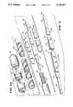
- FIG. 1is a perspective view of a catheter that embodies the features of the invention
- FIG. 2Ais a side section view of the catheter taken generally along line 2A--2A in FIG. 1;
- FIG. 2Bis an exploded view of FIG. 2A;
- FIG. 3Ais an exploded view of the electrode tip assembly of the catheter
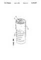
- FIG. 3Bis a view of an alternative guide tube shaft for the catheter
- FIG. 4is a perspective view of the stiffening assembly for the support wire of the catheter
- FIGS. 5A to Dshow the assembly of reinforcing tube that surrounds the support wire of the catheter
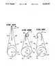
- FIGS. 6A to Cshow the steering mechanism for Curve Option 1 of the catheter
- FIGS. 7A to Cshow the steering mechanism for Curve Option 2 of the catheter
- FIGS. 8A to Cshow the steering mechanism for Curve Option 3 of the catheter
- FIGS. 9A to Cshow the steering mechanism for Curve Option 4 of the catheter.
- FIGS. 10A to Cshow the steering mechanism for Curve Option 5 of the catheter.
- FIG. 1shows the assembly of a steerable catheter 10 that embodies the features of the invention.
- the catheter 10includes three main parts or assemblies: the handle assembly 12, the guide tube assembly 14, and the electrode tip assembly 16.
- the catheter 10can be used in many different environments. This specification will describe the catheter 10 as used to provide electrophysiologic therapy in the interior regions of the heart.
- a physiciangrips the handle assembly 12 to steer the guide tube assembly 14 through a main vein or artery (which is typically the femoral arterial) into the interior region of the heart that is to be treated.
- the physicianthen further manipulates a steering mechanism 18 on the handle assembly 12 (which will be described later) to place the electrode tip assembly 16 in contact with the tissue that is to be ablated.
- the physiciandirects radio frequency energy into the electrode tip assembly 16 to ablate the tissue contacting the electrode tip assembly 16.
- the handle assembly 12includes a housing 20 that encloses the steering mechanism 18.
- the steering mechanism 18includes a rotating cam wheel 22 carried on a screw 24 within the housing 20.
- the cam wheel 22is seated for rotation between a top washer 26 and a bottom washer 28.
- a lock nut 30 and a pin 32couple an external steering lever to the top of the cam wheel 22.
- the steering lever 34seats against an O-ring 36.
- Movement of the steering lever 34 by the userrotates the cam wheel 22 about the screw 24 within the housing 20. Clockwise movement of the steering level rotates the cam wheel 22 to the right. Counterclockwise movement of the steering wheel rotates the cam wheel 22 to the left. Contact between the steering lever 34 and the side of the housing 20 physically limits the range of left and right rotation of the cam wheel 22 within the housing 20.
- the steering mechanism 18also includes an external locking lever 38 that an adhesive couples to the head of the screw 24.
- the locking lever 38seats against another O-ring 36.
- Movement of the locking lever 38rotates the screw 24. Clockwise rotation of the locking lever 38 tightens the screw 24 to increase the seating force between the cam wheel 22 and the bottom washer 28.
- the locking lever 38When moved fully clockwise into contact against the housing 20, the locking lever 38 imposes a seating force that prevents rotation of the cam wheel 22 by the steering lever 34. Counterclockwise movement of the locking lever 34 loosens the screw 24 to decrease the seating force and free the cam wheel 22 for rotation.
- the cam wheel 22includes a forward cam face 40 and a rear cam face 42.
- the forward cam face 40is oriented toward the front of the housing 20, where the guide tube assembly 14 attaches.
- the forward cam faceincludes a right side surface 44 and a left side surface 46.
- the rear cam face 42is oriented toward the back of the housing 20, where a coaxial cable 48 attaches.
- the rear cam faceincludes right and left side surfaces 50 and 52.
- the cam wheel 22also carries a wire fastener 54 between the right and left side surfaces 50 and 52 of the rear cam face 42.
- the wire fastener 54holds the proximal ends of right and left catheter steering wires 56 and 58, which are soldered to the interior of the fastener 54.
- the steering wires 56 and 58extend from the opposite ends of the fastener 54 and along the associated left and right side surfaces 44/46 and 50/52 of the front and rear cam faces 40 and 42.
- the steering wiresexit the front of the housing 20 through the interior bore of a tension screw assembly 60.
- the distal ends of the steering wires 56 and 58are attached to the electrode tip assembly 16. They extend from the wire fastener 54 through the guide tube assembly 14 to the electrode tip assembly 16.
- the wire fastener 54 in association with the cam faces 40 and 42translate rotation of the cam wheel 22 into lateral pulling movement of the steering wires 56 and 58 attached to the electrode tip assembly 16.
- the left steering wire 58By rotating the cam wheel 22 to the left (by moving the steering lever 34 counterclockwise), the left steering wire 58 bears against the left front and rear cam surfaces 46 and 52. The cam surfaces 46 and 52 tension the left steering wire 58 to impose a discrete, constant pulling force that causes the electrode tip assembly 16 to bend to the left.
- the right steering wire 56bears against the right front and rear cam surfaces 44 and 56.
- the cam surfaces 44 and 56tension the right steering wire 56 to impose a discrete, constant pulling force that causes the electrode tip assembly 16 to bend to the right.
- Rotation of the tension screw assembly 60additionally varies the amount of slack (i.e., tension) in the steering wires 56 and 58 between the wire fastener 54 and the distal ends of the steering wires 56 and 58. This controls the responsiveness of the electrode tip assembly 16 to rotation of the cam wheel 22.
- slacki.e., tension
- the component parts of the handle assembly 12can be constructed of various materials, depending upon the durability needed and the sterilization process used.
- the housing 20 and bottom washer 28can be made of a polycarbonate material.
- the cam wheel 22, steering lever 34, and locking lever 38can be made of a delrin material. These plastic materials are durable and EtO sterilizable.
- the lock nut 30, pin 32, and screw 24are preferably made of a metallic material like brass or stainless steel.
- the guide tube assembly 14includes a flexible shaft 62 attached to the handle assembly 12.
- the flexible shaft 62encloses an interior bore 64.
- the steering wires 56 and 58pass through the interior bore 64.
- the shaft 62may constructed in various ways.
- the shaft 62comprises a length of stainless steel coiled into a flexible spring enclosing the interior bore 64.
- a braided sheath 66 of plastic materialencloses the coil.
- the shaft 62comprises a slotted, stainless steel tube enclosing the interior bore 64.
- An array of slots 70subtends the tube along its length.
- the slots 70subtend less than one circumference of the shaft 62 at an angle of between 270 to 300 degrees.
- the slots 70are also radially offset one from the other by about 30 to 120 degrees.
- the slotted shaft 62 shown in FIG. 3Bprovides strength and flexibility along the length of the guide tube assembly 14.
- the slotted shaft 62also transmits twisting motions (torque) from the handle assembly 12 to the electrode tip assembly 16 more directly than the coiled shaft 62 shown in FIG. 3. Further details of the slotted shaft 62 are disclosed in pending Lundquist U.S. patent application Ser. No. 07/657,106 filed Feb. 15, 1991 and entitled "Torquable Catheter and Method.”
- a sheath 66encloses the slotted shaft.
- the sheath 66is made from a plastic material, such as polyolefin.
- the handle assembly 12includes a tubular stem 74 though which the proximal end of the guide tube assembly 14 extends for attachment to the tension screw assembly 60. Adhesive attaches the proximal end of the coil to the tension screw assembly 60.
- the guide tube assembly 14can be made in various lengths. In the illustrated, the guide tube assembly 14 is about 100 cm in length.
- a sleeve 76couples the guide tube assembly 14 to the handle assembly 12. Adhesive secures one end of the sleeve 76 to the handle stem 74.
- the sleeve 76includes an interior bore that progressively tapers from the handle stem 74 into a tight interference fit about the sheath 66 of the guide tube assembly 14.
- the exterior of the sleeve 76also tapers, extending about 4 to 5 inches beyond the front of the handle housing 20.
- the sleeve 76is made of a material having a high coefficient of friction, like Krayton G2703.
- the sleeve 76provides a gripping surface to help the user manipulate the catheter 10.
- the sleeve 76also significantly enhances the transmission of torque from the handle assembly 12 to the electrode tip assembly 16 through the guide tube assembly 14.
- the electrode tip assembly 16includes a bendable main support wire 78 having left and right faces 78L and 78R.
- the main support wire 78is made of stainless steel flat wire stock in an elongated shape about 0.035 inch wide and about 0.005 inch thick.
- the main support wire 78is about 3 inches in total length.
- the opposite ends of the main support wire 78are cut away to form stepped shoulders 80 and 82.
- the shoulders 80 and 82are about 0.024 inch wide and aligned along the centerline of the main support wire 78.
- Each shoulder 80 and 82is about 0.12 inch in length.
- one stepped shoulder 80fits within the distal end of the flexible guide tube shaft 62 to append the electrode tip assembly 16 to the guide tube assembly 14.
- the left and right faces 78L and 78R of the main support wire 78lie in a plane that is generally parallel to the axis about which the cam wheel 22 rotates. Stated differently, when the user holds the handle assembly 12 in a horizontal plane, the left and right faces 78L and 78R of the main support wire 78 lie in a vertical plane.
- the distal end of the left steering wire 58is soldered to the left face 78L of the main support wire 78.
- the left steering wire 58bends the main support wire 78 to the left.
- the distal end of the right steering wire 56is soldered to the right face 78R of the main support wire 78.
- the right steering wire 56bends the main support wire 78 to the right.
- the stiffness of the main support wire 78is not uniform, but varies along its length. Its stiffest point is near its proximal end region, where it joins the guide tube shaft 62. Its stiffness is least at the tip end 88 of the shoulder 82.
- the stiffness of the main support wire 78By varying the stiffness of the main support wire 78 between its proximal end and its distal tip end 88, the base of the electrode tip assembly 16 (where it joins the guide tube assembly 14) resists bending and buckling. The bending forces generated by the steering wires 56 and 58 are directed toward the distal tip end 88 of the main support wire 78.
- the variable stiffness of the main support wire 78concentrates the bending forces at the distal tip end 88 of the electrode tip assembly 16.
- One wayis to vary the thickness of the main support wire 78 as it is manufactured, so that it is thickest (i.e., most stiff) near the shoulder 80 that, in use, is fitted within the guide tube shaft 62.
- a stiffening spring assembly 90stiffens the center support near the distal end of the guide tube shaft 62.
- the stiffening spring assembly 90includes two leaf springs 92 that sandwich the main support wire 78 between them.
- Each leaf spring 92is made of stainless steel flat wire stock in an elongated shape that is about 0.039 inch wide and about 0.0029 inch thick.
- the stiffening spring assembly 90can sized and configured to provide the degrees of stiffness and variance wanted. In the illustrated embodiment, the stiffening spring assembly 90 stiffens the main support wire 78 beginning about 0.030 to 0.050 inch from the inner edge of the attachment shoulder 80 and extending from there about 1.5 inches.
- spot welds 94secure the leaf springs 92 to the main support wire 78.
- the three spot welds 94 shownare clustered near the proximal end of the stiffening spring assembly 90. There, they are evenly spaced, with the most distal spot weld 94 being about 0.10 inch from the proximal end of the stiffening spring assembly 90.
- the distal end of the electrode tip assembly 16carries an ablation tip electrode 96 and three ring electrodes 98.
- Interior conducting wires 100are connected to the tip electrode 96 and the three ring electrodes 98.
- the conducting wires 100extend along the main support wire 78, through the interior bore of the guide tube shaft 62, and into the handle housing 20 to join the coaxial cable 48 that extends from the rear of the housing 20.
- the coaxial cable 48ends with plugs 102.
- the plugs 102connect with appropriate conventional catheter control equipment (not shown).
- the conducting wires 100transfer electrical current from the ring electrodes 98 indicative of electrical activity within the heart.
- the conducting wires 100also transfer radio frequency energy to the tip electrode 96 to carry out ablation procedures within the heart.
- the illustrated embodimentemploys a reinforcing sleeve assembly 104 for this purpose.
- the reinforcing sleeve assembly 104is made in association with a specially designed sleeve mandrel 106.
- the sleeve mandrel 106is made from stainless steel and is about 7 inches in total length.
- the mandrel 106has a first cylindrical body portion 108 and second cylindrical body portion 110 having an enlarged diameter.
- the first body portion 108is about 0.032 inch in diameter and is about 5 inches long.
- the second body portion 110has an enlarged diameter of about 0.043 inch and is about 2 inches long.
- the first body portion 108 and the second body portion 110each includes an inwardly sloping notch 112.
- a sleeve mandrel 106receives a first heat shrink tube 114 that, in the illustrated embodiment, is about 4.5 inches long. A portion of the first tube 114 is pulled over the second body portion 110 of the mandrel 106. Heat is applied using an oven or heat gun to shrink the tube in place upon the sleeve mandrel 106.
- a reinforcing fabric 116is wrapped in tension over the first tube 114 while still on the mandrel 106.
- the fabric 116is wrapped as a single spiral about the first tube 114 to obtain a desired, closely spaced pitch. In the illustrated embodiment the fabric 116 is wrapped to a pitch of about 18 to 20 wraps per inch.
- the notches 112 on the sleeve mandrel 106hold the fabric 116 in tension during this step of the manufacturing process.
- the mandrel 106now receives a second heat shrink tube 118 over the fabric-wrapped first tube 114 (see FIGS. 5B and 5C).
- the second tube 118is shorter than the first tube 114, and is not pulled over the second body portion 110 of the sleeve mandrel 106.
- the second tube 118is about 4.0 inches long.
- Heatis again applied using an oven or heat gun to shrink the second tube 118 in place over the fabric-wrapped first tube 114.
- the second tube 118captures and encases the wrapped fabric 116 and underlying first tube 114 (as FIG. 5C shows).
- the fabric 116 extending from the second tube 118 to the notches 112is cut away.
- the reinforcing sleeve assembly 104is removed from mandrel 106.
- the reinforcing sleeve assembly 104is inserted over the main support wire 78 appended to the distal end of the guide shaft 62 (see FIG. 3A) so that the enlarged diameter portion of the reinforcing sleeve assembly 104 slips over the distal end of the guide shaft 62.
- the left and right steering wires 56 and 58 and stiffening spring assembly 90are attached to the main support wire 78.
- the conducting wires 100also extend along the main support wire 78 and into the bore of the guide shaft 62.
- Heatis again applied using an oven or heat gun to finally shrink the second tube 118 in place over distal end of the guide shaft 62 and over the main support wire 78 and its associated parts.
- the reinforcing sleeve assembly 104tightly encases the main support wire 78.
- the wrapped fabric 116becomes an integrated part of the reinforcing sleeve assembly 104.
- the reinforcing sleeve assembly 104is flexible enough to accommodate the bending movement desired for the electrode tip assembly 16. Still, due to the wrapped fabric 116, the reinforcing sleeve assembly 10 provides added strength and resistance against wear and tear during repeated bending operations.
- the reinforcing sleeve assembly 104also holds the steering wires 56 and 58 and conducting wires 100 in close intimate contact against the main support wire 78.
- the intimate contactprevents kinking and chafing of the steering wires 56 and 58 and conducting wires 100 during bending operations.
- the materials used to make the reinforcing sleeve assembly 104can vary.
- the shrink tubes 114 and 118are made from medical grade TFE Teflon material having a 2 to 1 shrink ratio.
- the material usedhas a wall thickness (after heat shrinkage) of about 0.003 to 0.0045 inch.
- the fabric 116is a Kevlar 49 Yarn (which is available from DuPont). This material has a tensile strength of about 400,000 lbs/in 2 and a modulus of about 18,000,000 lbs/in 2 .
- An outer tube 120covers the reinforcing sleeve assembly 104.
- the tip electrode 96 and ring electrodes 98are attached to the conducting wires 100 and joined to the outer tube 120 by conventional methods to complete the electrode tip assembly 16.
- the curvature assumed upon bending the electrode tip assembly 16 to the leftis different that the curvature assumed upon bending the electrode tip assembly 16 to the right.
- the electrode tip assembly 16assumes one curvature when bent to the left and a different curvature when bent to the right. These different left and right curvatures provide the physician with flexibility in steering the tip electrode 96 into position. These differing curvatures will be called asymmetric curves.
- the first relationshipis that between the cam radius on the left side surfaces 46 and 52 of the forward cam and rear cam faces 40 and 42, and the cam radius on the right side surfaces 44 and 50 of the forward and rear cam faces 40 and 42.
- the cam radiidiffer, forming various asymmetric cam arrangements.
- the second relationshipis that between the point of attachment of the left steering wire 58 on the left face 78L of the main support wire 78 and the point of attachment of the right steering wire 56 on the right face 78R of the main support wire 78.
- the point of attachmentcan be varied, forming both symmetrical and asymmetric steering wire attachment sites.
- Combinations of asymmetric cam arrangements and symmetrical and asymmetric steering wire attachmentscreate differing asymmetric curve options.
- the five curve options shownare intended to illustrate the ideas of forming asymmetric curves by varying the two relationships, but they do not encompass all the possible curve options that can be made.
- the catheter 10includes an asymmetric forward cam face 40 on the cam wheel 22 and a symmetrical rear cam face 42.
- the electrode tip assembly 16includes asymmetric attachments of the left and right steering wires 56 and 58 to the left and right faces 78L and 78R of the main support wire 78.
- the right side surface 44 of the forward cam face 40is formed with a radius of 0.3125 inch, while the left side surface 46 of the forward cam face 40 is formed with a radius of 0.4062 inch.
- the right and left side surfaces 50 and 52 of the rear cam face 42each has a radius of 0.313".
- the right steering wire 56is attached at the distal tip 88 of the main support wire 78, while the left steering wire 58 is attached about 1.5 inches from the distal tip 88 of the main support wire 78.
- the catheter 10includes symmetrical forward and rear cam faces 40 and 42 on the cam wheel 22 in combination an asymmetric attachment of the left and right steering wires 56 and 58 to the main support wire 78 to achieve the asymmetric left and right curves in Option 2.
- the right side surface 44 and the left side surface 46 of the forward cam face 40are both formed with a radius of 0.4062 inch.
- the right side surface 50 and the left side surface 52 of the rear cam face 42are both formed with a radius of 0.313".
- the right steering wire 56is attached at the distal tip 88 of the main support wire 78, while the left steering wire 58 is attached about 1.5 inches from the distal tip of the main support wire 78.
- the catheter 10includes an asymmetric forward cam face 40 on the cam wheel 22 and a symmetrical rear cam face 42.
- the electrode tip assembly 16includes symmetrical attachments of the left and right steering wires 56 and 58 to the left and right faces 78L and 78R of the main support wire 78.
- the right side surface 44 of the forward cam face 40is formed with a radius of 0.3125 inch, while the left side surface 46 of the forward cam face 40 is formed with a radius of 0.4062 inch.
- the right and left side surfaces 50 and 52 of the rear cam face 42each has a radius of 0.313".
- the right and left steering wires 56 and 58are attached at the distal tip 88 of the main support wire 78.
- both forward and rear cam faces 40 and 42 on the cam wheel 22are asymmetric.
- the electrode tip assembly 16includes a symmetrical attachment of the left and right steering wires 56 and 58 to the main support wire 78.
- the right side surface 44 of the forward cam face 40is formed with a radius of 0.3125 inch.
- the left side surface 52 of the forward cam face 40is formed as a straight (i.e., linear) line.
- the linear lineextends along a tangent from an interior hub 68 of the cam wheel 22 to intersect the curved (i.e., nonlinear) right side surface 44.
- the left side surface 52 of the rear cam face 42extends arcuately from the tangent along the circumference of the interior hub 68.
- the right side surface 50is asymmetrically formed with a radius of 0.313".
- the right steering wire 56 and the left steering wire 52are both attached at the distal tip 88 of the main support wire 78.
- the catheter 10includes an asymmetric forward cam face 40 and a symmetrical rear cam face 42.
- the electrode tip assembly 16includes symmetrical attachments of the left and right steering wires 56 and 58 to the main support wire 78.
- the right side surface 50 of the forward cam face 40is formed with a radius of 0.3125 inch, while the left side surface 46 of the forward cam face 40 is formed with a radius of 0.4062 inch.
- the left and right side surfaces 50 and 52 of the rear cam face 42are each formed with a radius of 0.313".
- the right steering wire 56 and the left steering wire 58are both attached at the distal tip 88 of the main support wire 78.
Landscapes
- Health & Medical Sciences (AREA)
- Life Sciences & Earth Sciences (AREA)
- Engineering & Computer Science (AREA)
- Anesthesiology (AREA)
- Biophysics (AREA)
- Pulmonology (AREA)
- Biomedical Technology (AREA)
- Heart & Thoracic Surgery (AREA)
- Hematology (AREA)
- Animal Behavior & Ethology (AREA)
- General Health & Medical Sciences (AREA)
- Public Health (AREA)
- Veterinary Medicine (AREA)
- Mechanical Engineering (AREA)
- Media Introduction/Drainage Providing Device (AREA)
Abstract
Description
The invention generally relates to catheters. In a more specific sense, the invention relates to catheters that can be steered and manipulated within interior regions of the body from a location outside the body.
Physicians make widespread use of catheters today in medical procedures to gain access into interior regions of the body. In its important that the physician can control carefully and precisely the movement of the catheter within the body.
The need for careful and precise control over the catheter is especially critical during procedures that ablate tissue within the heart. These procedures, called electrophysiological therapy, are becoming more widespread for treating cardiac rhythm disturbances.
During these procedures, a physician steers a catheter through a main vein or artery (which is typically the femoral arterial) into the interior region of the heart that is to be treated. The physician then further manipulates a steering mechanism to place the electrode carried on the tip of the catheter into direct contact with the tissue that is to be ablated. The physician directs radio frequency energy into the electrode tip to ablate the tissue and form a lesion.
Cardiac ablation especially requires the ability to precisely bend and shape the tip end of the catheter to position the ablation electrode.
The invention provides a sleeve for transmitting torque from a handle to the distal end of a catheter.
In a preferred embodiment, the invention provides a catheter comprising a handle and a guide tube enclosing a interior bore. The guide tube including an array of slots that subtend the tube along its length to impart flexibility. The guide tube has a proximal end and a distal end.
According to the invention, a sleeve having a high co-efficient of friction joins the proximal end of the guide tube to the handle. The frictional sleeve extends from the handle and grips a portion of the guide tube beyond the handle. The sleeve transmits torque applied at the handle to the distal end of the guide tube.
Because the sleeve grips a portion of the guide tube beyond the handle, it also forms a hand grip for the user to hold beyond the confines of the handle.
FIG. 1 is a perspective view of a catheter that embodies the features of the invention;
FIG. 2A is a side section view of the catheter taken generally alongline 2A--2A in FIG. 1;
FIG. 2B is an exploded view of FIG. 2A;
FIG. 3A is an exploded view of the electrode tip assembly of the catheter;
FIG. 3B is a view of an alternative guide tube shaft for the catheter;
FIG. 4 is a perspective view of the stiffening assembly for the support wire of the catheter;
FIGS. 5A to D show the assembly of reinforcing tube that surrounds the support wire of the catheter;
FIGS. 6A to C show the steering mechanism for Curve Option 1 of the catheter;
FIGS. 7A to C show the steering mechanism for Curve Option 2 of the catheter;
FIGS. 8A to C show the steering mechanism for Curve Option 3 of the catheter;
FIGS. 9A to C show the steering mechanism for Curve Option 4 of the catheter; and
FIGS. 10A to C show the steering mechanism for Curve Option 5 of the catheter.
FIG. 1 shows the assembly of asteerable catheter 10 that embodies the features of the invention. As there shown, thecatheter 10 includes three main parts or assemblies: thehandle assembly 12, theguide tube assembly 14, and theelectrode tip assembly 16.
Thecatheter 10 can be used in many different environments. This specification will describe thecatheter 10 as used to provide electrophysiologic therapy in the interior regions of the heart.
When used for this purpose, a physician grips thehandle assembly 12 to steer theguide tube assembly 14 through a main vein or artery (which is typically the femoral arterial) into the interior region of the heart that is to be treated. The physician then further manipulates asteering mechanism 18 on the handle assembly 12 (which will be described later) to place theelectrode tip assembly 16 in contact with the tissue that is to be ablated. The physician directs radio frequency energy into theelectrode tip assembly 16 to ablate the tissue contacting theelectrode tip assembly 16.
As FIGS. 2A and 2B best show, thehandle assembly 12 includes ahousing 20 that encloses thesteering mechanism 18. Thesteering mechanism 18 includes a rotatingcam wheel 22 carried on ascrew 24 within thehousing 20. Thecam wheel 22 is seated for rotation between atop washer 26 and abottom washer 28. Alock nut 30 and apin 32 couple an external steering lever to the top of thecam wheel 22. The steering lever 34 seats against an O-ring 36.
Movement of thesteering lever 34 by the user rotates thecam wheel 22 about thescrew 24 within thehousing 20. Clockwise movement of the steering level rotates thecam wheel 22 to the right. Counterclockwise movement of the steering wheel rotates thecam wheel 22 to the left. Contact between thesteering lever 34 and the side of thehousing 20 physically limits the range of left and right rotation of thecam wheel 22 within thehousing 20.
Thesteering mechanism 18 also includes anexternal locking lever 38 that an adhesive couples to the head of thescrew 24. The locking lever 38 seats against another O-ring 36.
Movement of the lockinglever 38 rotates thescrew 24. Clockwise rotation of the lockinglever 38 tightens thescrew 24 to increase the seating force between thecam wheel 22 and thebottom washer 28. When moved fully clockwise into contact against thehousing 20, the lockinglever 38 imposes a seating force that prevents rotation of thecam wheel 22 by the steeringlever 34. Counterclockwise movement of the lockinglever 34 loosens thescrew 24 to decrease the seating force and free thecam wheel 22 for rotation.
Thecam wheel 22 includes aforward cam face 40 and arear cam face 42. The forward cam face 40 is oriented toward the front of thehousing 20, where theguide tube assembly 14 attaches. The forward cam face includes aright side surface 44 and aleft side surface 46.
Therear cam face 42 is oriented toward the back of thehousing 20, where acoaxial cable 48 attaches. The rear cam face includes right and left side surfaces 50 and 52.
Thecam wheel 22 also carries awire fastener 54 between the right and left side surfaces 50 and 52 of therear cam face 42. Thewire fastener 54 holds the proximal ends of right and leftcatheter steering wires fastener 54.
Thesteering wires fastener 54 and along the associated left and right side surfaces 44/46 and 50/52 of the front and rear cam faces 40 and 42. The steering wires exit the front of thehousing 20 through the interior bore of atension screw assembly 60.
As will be described in greater detail later, the distal ends of thesteering wires electrode tip assembly 16. They extend from thewire fastener 54 through theguide tube assembly 14 to theelectrode tip assembly 16.
As also will be described in greater detail, thewire fastener 54 in association with the cam faces 40 and 42 translate rotation of thecam wheel 22 into lateral pulling movement of thesteering wires electrode tip assembly 16.
By rotating thecam wheel 22 to the left (by moving the steeringlever 34 counterclockwise), theleft steering wire 58 bears against the left front and rear cam surfaces 46 and 52. The cam surfaces 46 and 52 tension theleft steering wire 58 to impose a discrete, constant pulling force that causes theelectrode tip assembly 16 to bend to the left.
Also, by rotating thecam wheel 22 to the right (by moving the steeringlever 34 clockwise), theright steering wire 56 bears against the right front and rear cam surfaces 44 and 56. The cam surfaces 44 and 56 tension theright steering wire 56 to impose a discrete, constant pulling force that causes theelectrode tip assembly 16 to bend to the right.
Rotation of thetension screw assembly 60 additionally varies the amount of slack (i.e., tension) in thesteering wires wire fastener 54 and the distal ends of thesteering wires electrode tip assembly 16 to rotation of thecam wheel 22.
The component parts of thehandle assembly 12 can be constructed of various materials, depending upon the durability needed and the sterilization process used.
For example, when EtO sterilization is used, thehousing 20 andbottom washer 28 can be made of a polycarbonate material. In this arrangement, thecam wheel 22, steeringlever 34, and lockinglever 38 can be made of a delrin material. These plastic materials are durable and EtO sterilizable. In this assembly, thelock nut 30,pin 32, and screw 24 are preferably made of a metallic material like brass or stainless steel.
As FIG. 3A shows, theguide tube assembly 14 includes aflexible shaft 62 attached to thehandle assembly 12. Theflexible shaft 62 encloses aninterior bore 64. Thesteering wires
Theshaft 62 may constructed in various ways. In the embodiment shown in FIG. 3, theshaft 62 comprises a length of stainless steel coiled into a flexible spring enclosing the interior bore 64. Abraided sheath 66 of plastic material encloses the coil.
Alternatively (as FIG. 3B shows), theshaft 62 comprises a slotted, stainless steel tube enclosing the interior bore 64. An array ofslots 70 subtends the tube along its length. Theslots 70 subtend less than one circumference of theshaft 62 at an angle of between 270 to 300 degrees. Theslots 70 are also radially offset one from the other by about 30 to 120 degrees.
The slottedshaft 62 shown in FIG. 3B provides strength and flexibility along the length of theguide tube assembly 14. The slottedshaft 62 also transmits twisting motions (torque) from thehandle assembly 12 to theelectrode tip assembly 16 more directly than the coiledshaft 62 shown in FIG. 3. Further details of the slottedshaft 62 are disclosed in pending Lundquist U.S. patent application Ser. No. 07/657,106 filed Feb. 15, 1991 and entitled "Torquable Catheter and Method."
Like the coiledshaft 62 in FIG. 3A, asheath 66 encloses the slotted shaft. Thesheath 66 is made from a plastic material, such as polyolefin.
Thehandle assembly 12 includes atubular stem 74 though which the proximal end of theguide tube assembly 14 extends for attachment to thetension screw assembly 60. Adhesive attaches the proximal end of the coil to thetension screw assembly 60.
Theguide tube assembly 14 can be made in various lengths. In the illustrated, theguide tube assembly 14 is about 100 cm in length.
As FIGS. 1 and 2A/B show, asleeve 76 couples theguide tube assembly 14 to thehandle assembly 12. Adhesive secures one end of thesleeve 76 to thehandle stem 74. Thesleeve 76 includes an interior bore that progressively tapers from thehandle stem 74 into a tight interference fit about thesheath 66 of theguide tube assembly 14. The exterior of thesleeve 76 also tapers, extending about 4 to 5 inches beyond the front of thehandle housing 20.
Thesleeve 76 is made of a material having a high coefficient of friction, like Krayton G2703. Thesleeve 76 provides a gripping surface to help the user manipulate thecatheter 10. When used in association with the slotted tube, thesleeve 76 also significantly enhances the transmission of torque from thehandle assembly 12 to theelectrode tip assembly 16 through theguide tube assembly 14.
Theelectrode tip assembly 16 includes a bendablemain support wire 78 having left andright faces main support wire 78 is made of stainless steel flat wire stock in an elongated shape about 0.035 inch wide and about 0.005 inch thick. Themain support wire 78 is about 3 inches in total length.
The opposite ends of themain support wire 78 are cut away to form steppedshoulders shoulders main support wire 78. Eachshoulder
As FIG. 3A shows, one steppedshoulder 80 fits within the distal end of the flexibleguide tube shaft 62 to append theelectrode tip assembly 16 to theguide tube assembly 14. When properly oriented, the left andright faces main support wire 78 lie in a plane that is generally parallel to the axis about which thecam wheel 22 rotates. Stated differently, when the user holds thehandle assembly 12 in a horizontal plane, the left andright faces main support wire 78 lie in a vertical plane.
As FIG. 3A shows, the distal end of theleft steering wire 58 is soldered to theleft face 78L of themain support wire 78. When pulled by left rotation of thecam wheel 22, theleft steering wire 58 bends themain support wire 78 to the left.
Also, the distal end of theright steering wire 56 is soldered to theright face 78R of themain support wire 78. When pulled by right rotation of thecam wheel 22, theright steering wire 56 bends themain support wire 78 to the right.
In the illustrated embodiment, the stiffness of themain support wire 78 is not uniform, but varies along its length. Its stiffest point is near its proximal end region, where it joins theguide tube shaft 62. Its stiffness is least at thetip end 88 of theshoulder 82. By varying the stiffness of themain support wire 78 between its proximal end and itsdistal tip end 88, the base of the electrode tip assembly 16 (where it joins the guide tube assembly 14) resists bending and buckling. The bending forces generated by thesteering wires distal tip end 88 of themain support wire 78. The variable stiffness of themain support wire 78 concentrates the bending forces at thedistal tip end 88 of theelectrode tip assembly 16.
There are various ways to varying the stiffness of themain support wire 78 along its length. One way (not shown) is to vary the thickness of themain support wire 78 as it is manufactured, so that it is thickest (i.e., most stiff) near theshoulder 80 that, in use, is fitted within theguide tube shaft 62.
In the illustrated and preferred embodiment (see FIG. 4), a stiffeningspring assembly 90 stiffens the center support near the distal end of theguide tube shaft 62. The stiffeningspring assembly 90 includes twoleaf springs 92 that sandwich themain support wire 78 between them. Eachleaf spring 92 is made of stainless steel flat wire stock in an elongated shape that is about 0.039 inch wide and about 0.0029 inch thick.
The stiffeningspring assembly 90 can sized and configured to provide the degrees of stiffness and variance wanted. In the illustrated embodiment, the stiffeningspring assembly 90 stiffens themain support wire 78 beginning about 0.030 to 0.050 inch from the inner edge of theattachment shoulder 80 and extending from there about 1.5 inches.
In the illustrated embodiment,spot welds 94 secure theleaf springs 92 to themain support wire 78. The threespot welds 94 shown are clustered near the proximal end of the stiffeningspring assembly 90. There, they are evenly spaced, with the mostdistal spot weld 94 being about 0.10 inch from the proximal end of the stiffeningspring assembly 90.
In the illustrated embodiment, the distal end of theelectrode tip assembly 16 carries anablation tip electrode 96 and three ring electrodes 98. Interior conducting wires 100 are connected to thetip electrode 96 and the three ring electrodes 98. The conducting wires 100 extend along themain support wire 78, through the interior bore of theguide tube shaft 62, and into thehandle housing 20 to join thecoaxial cable 48 that extends from the rear of thehousing 20.
Thecoaxial cable 48 ends withplugs 102. Theplugs 102 connect with appropriate conventional catheter control equipment (not shown). The conducting wires 100 transfer electrical current from the ring electrodes 98 indicative of electrical activity within the heart. The conducting wires 100 also transfer radio frequency energy to thetip electrode 96 to carry out ablation procedures within the heart.
There are various ways of securing the attachment between theelectrode tip assembly 16 and theguide tube assembly 14. The illustrated embodiment employs a reinforcingsleeve assembly 104 for this purpose.
As shown in the FIGS. 5A to D, the reinforcingsleeve assembly 104 is made in association with a specially designedsleeve mandrel 106. In the illustrated embodiment, thesleeve mandrel 106 is made from stainless steel and is about 7 inches in total length. As FIG. 5A shows, themandrel 106 has a firstcylindrical body portion 108 and secondcylindrical body portion 110 having an enlarged diameter. In the illustrated embodiment, thefirst body portion 108 is about 0.032 inch in diameter and is about 5 inches long. Thesecond body portion 110 has an enlarged diameter of about 0.043 inch and is about 2 inches long. Thefirst body portion 108 and thesecond body portion 110 each includes an inwardly slopingnotch 112.
In making the reinforcing sleeve assembly 104 (see FIG. 5A), asleeve mandrel 106 receives a firstheat shrink tube 114 that, in the illustrated embodiment, is about 4.5 inches long. A portion of thefirst tube 114 is pulled over thesecond body portion 110 of themandrel 106. Heat is applied using an oven or heat gun to shrink the tube in place upon thesleeve mandrel 106.
Next (see FIG. 5B), a reinforcingfabric 116 is wrapped in tension over thefirst tube 114 while still on themandrel 106. Thefabric 116 is wrapped as a single spiral about thefirst tube 114 to obtain a desired, closely spaced pitch. In the illustrated embodiment thefabric 116 is wrapped to a pitch of about 18 to 20 wraps per inch. Thenotches 112 on thesleeve mandrel 106 hold thefabric 116 in tension during this step of the manufacturing process.
Themandrel 106 now receives a secondheat shrink tube 118 over the fabric-wrapped first tube 114 (see FIGS. 5B and 5C). Thesecond tube 118 is shorter than thefirst tube 114, and is not pulled over thesecond body portion 110 of thesleeve mandrel 106. In the illustrated embodiment, thesecond tube 118 is about 4.0 inches long.
Heat is again applied using an oven or heat gun to shrink thesecond tube 118 in place over the fabric-wrappedfirst tube 114. When shrunk in place, thesecond tube 118 captures and encases the wrappedfabric 116 and underlying first tube 114 (as FIG. 5C shows).
Next (see FIG. 5D), thefabric 116 extending from thesecond tube 118 to thenotches 112 is cut away. The reinforcingsleeve assembly 104 is removed frommandrel 106.
The reinforcingsleeve assembly 104 is inserted over themain support wire 78 appended to the distal end of the guide shaft 62 (see FIG. 3A) so that the enlarged diameter portion of the reinforcingsleeve assembly 104 slips over the distal end of theguide shaft 62. At this time, the left andright steering wires spring assembly 90 are attached to themain support wire 78. The conducting wires 100 also extend along themain support wire 78 and into the bore of theguide shaft 62.
Heat is again applied using an oven or heat gun to finally shrink thesecond tube 118 in place over distal end of theguide shaft 62 and over themain support wire 78 and its associated parts. When finally shrunk in place, the reinforcingsleeve assembly 104 tightly encases themain support wire 78.
The wrappedfabric 116 becomes an integrated part of the reinforcingsleeve assembly 104. The reinforcingsleeve assembly 104 is flexible enough to accommodate the bending movement desired for theelectrode tip assembly 16. Still, due to the wrappedfabric 116, the reinforcingsleeve assembly 10 provides added strength and resistance against wear and tear during repeated bending operations.
The reinforcingsleeve assembly 104 also holds thesteering wires main support wire 78. The intimate contact prevents kinking and chafing of thesteering wires
The materials used to make the reinforcingsleeve assembly 104 can vary. In the illustrated embodiment, theshrink tubes fabric 116 is a Kevlar 49 Yarn (which is available from DuPont). This material has a tensile strength of about 400,000 lbs/in2 and a modulus of about 18,000,000 lbs/in2.
Anouter tube 120 covers the reinforcingsleeve assembly 104. Thetip electrode 96 and ring electrodes 98 are attached to the conducting wires 100 and joined to theouter tube 120 by conventional methods to complete theelectrode tip assembly 16.
In the illustrated embodiment, the curvature assumed upon bending theelectrode tip assembly 16 to the left is different that the curvature assumed upon bending theelectrode tip assembly 16 to the right. Theelectrode tip assembly 16 assumes one curvature when bent to the left and a different curvature when bent to the right. These different left and right curvatures provide the physician with flexibility in steering thetip electrode 96 into position. These differing curvatures will be called asymmetric curves.
The drawings show five representative asymmetric curve options that embody the features of the invention. The invention achieves the different curve options by varying two relationships.
The first relationship is that between the cam radius on the left side surfaces 46 and 52 of the forward cam and rear cam faces 40 and 42, and the cam radius on the right side surfaces 44 and 50 of the forward and rear cam faces 40 and 42. According to the invention, the cam radii differ, forming various asymmetric cam arrangements.
The second relationship is that between the point of attachment of theleft steering wire 58 on theleft face 78L of themain support wire 78 and the point of attachment of theright steering wire 56 on theright face 78R of themain support wire 78. According to the invention, the point of attachment can be varied, forming both symmetrical and asymmetric steering wire attachment sites.
Combinations of asymmetric cam arrangements and symmetrical and asymmetric steering wire attachments create differing asymmetric curve options. The five curve options shown are intended to illustrate the ideas of forming asymmetric curves by varying the two relationships, but they do not encompass all the possible curve options that can be made.
As FIGS. 6A to C show, thecatheter 10 includes an asymmetric forward cam face 40 on thecam wheel 22 and a symmetricalrear cam face 42. In addition, theelectrode tip assembly 16 includes asymmetric attachments of the left andright steering wires right faces main support wire 78.
More particularly, theright side surface 44 of the forward cam face 40 is formed with a radius of 0.3125 inch, while theleft side surface 46 of the forward cam face 40 is formed with a radius of 0.4062 inch. The right and left side surfaces 50 and 52 of the rear cam face 42 each has a radius of 0.313".
Theright steering wire 56 is attached at thedistal tip 88 of themain support wire 78, while theleft steering wire 58 is attached about 1.5 inches from thedistal tip 88 of themain support wire 78.
When the steeringlever 34 is rotated clockwise, the foregoing relationships bend themain support wire 78 about 270 degrees to the right to form a looping "pigtail" curve. When the steeringlever 34 is rotated counterclockwise, the foregoing relationships bend themain support wire 78 about 90 degrees to the left to form an elbow curve.
As FIGS. 7A to C show, thecatheter 10 includes symmetrical forward and rear cam faces 40 and 42 on thecam wheel 22 in combination an asymmetric attachment of the left andright steering wires main support wire 78 to achieve the asymmetric left and right curves in Option 2.
More particularly, theright side surface 44 and theleft side surface 46 of the forward cam face 40 are both formed with a radius of 0.4062 inch. Theright side surface 50 and theleft side surface 52 of therear cam face 42 are both formed with a radius of 0.313".
Theright steering wire 56 is attached at thedistal tip 88 of themain support wire 78, while theleft steering wire 58 is attached about 1.5 inches from the distal tip of themain support wire 78.
When the steeringlever 34 is rotated clockwise, the foregoing relationships bend themain support wire 78 about 135 degrees to the right to form an open, arching curve. When the steeringlever 34 is rotated counterclockwise, the foregoing relationships bend themain support wire 78 about 90 degrees to the left to form an elbow curve (just as in Curve Option 1).
As FIGS. 8A to C show, thecatheter 10 includes an asymmetric forward cam face 40 on thecam wheel 22 and a symmetricalrear cam face 42. In addition, theelectrode tip assembly 16 includes symmetrical attachments of the left andright steering wires right faces main support wire 78.
More particularly, theright side surface 44 of the forward cam face 40 is formed with a radius of 0.3125 inch, while theleft side surface 46 of the forward cam face 40 is formed with a radius of 0.4062 inch. The right and left side surfaces 50 and 52 of the rear cam face 42 each has a radius of 0.313".
The right and leftsteering wires distal tip 88 of themain support wire 78.
When the steeringlever 34 is rotated clockwise, the foregoing relationships bend themain support wire 78 about 270 degrees to the right to form a looping "pigtail" curve (as in Curve Option 1, where the same cam and steering wire relationships exist on the right side). When the steeringlever 34 is rotated counterclockwise, the foregoing relationships bend themain support wire 78 about 80 degrees to the left to form a partial arch.
As FIGS. 9A to C show, both forward and rear cam faces 40 and 42 on thecam wheel 22 are asymmetric. Theelectrode tip assembly 16 includes a symmetrical attachment of the left andright steering wires main support wire 78.
More particularly, theright side surface 44 of the forward cam face 40 is formed with a radius of 0.3125 inch. Theleft side surface 52 of the forward cam face 40 is formed as a straight (i.e., linear) line. The linear line extends along a tangent from an interior hub 68 of thecam wheel 22 to intersect the curved (i.e., nonlinear)right side surface 44.
Theleft side surface 52 of therear cam face 42 extends arcuately from the tangent along the circumference of the interior hub 68. In contrast, theright side surface 50 is asymmetrically formed with a radius of 0.313".
Theright steering wire 56 and theleft steering wire 52 are both attached at thedistal tip 88 of themain support wire 78.
When the steeringlever 34 is rotated clockwise, the foregoing relationships bend themain support wire 78 in an open arch about 135 degrees. When the steeringlever 34 is rotated counterclockwise, the foregoing relationships bend the main support spring in a tighter arch about 135 degrees to the left to form a "shepard's crook" curve.
As FIGS. 10A to C show, thecatheter 10 includes an asymmetricforward cam face 40 and a symmetricalrear cam face 42. Theelectrode tip assembly 16 includes symmetrical attachments of the left andright steering wires main support wire 78.
More particularly, theright side surface 50 of the forward cam face 40 is formed with a radius of 0.3125 inch, while theleft side surface 46 of the forward cam face 40 is formed with a radius of 0.4062 inch. The left and right side surfaces 50 and 52 of therear cam face 42 are each formed with a radius of 0.313".
Theright steering wire 56 and theleft steering wire 58 are both attached at thedistal tip 88 of themain support wire 78.
When the steeringlever 34 is rotated clockwise, the foregoing relationships bend the main support spring about 270 degrees to the right to form the looping "pigtail" curve (as in Curve Options 1 and 3). When the steeringlever 34 is rotated counterclockwise, the foregoing relationships bend the main support spring about 135 degrees to the left to form a "shepard's crook" curve (like the right curve in Curve Option 4).
The following table summarizes the relationships that were varied to achieve Curve Options 1 to 5.
TABLE 1 ______________________________________ Asymmetric Curve Options 1 to 5 Curve Left Left Right Right Option Wire Cam* Wire Cam* ______________________________________ 1 1.5" .4062" Tip .3125" 2 1.5" .4062" Tip .4062" 3 0.75" .4062" Tip .3125" 4 Tip Linear Tip .4062" 5 Tip .4062" Tip .3125" ______________________________________ *Note: These columns refer to the left and right cam surfaces on the fron cam face. In Curve Options 1, 2, 3 and 5, the left and right cam surfaces of the rear cam face are symmetrical, having a radius of .313". In Curve Option 4, the left and right cam surfaces of the rear cam are asymmetric, with the right cam surface formed with a radius of .3125 inch and the lef cam face being linear (not curved).
Various features of the invention are set forth in the following claims.
Claims (4)
1. A catheter comprising a handle and a guide tube enclosing an interior bore, the guide tube including an array of slots subtending the tube along its length to impart flexibility, the guide tube having a proximal end and a distal end, the improvement comprising an elongated tapered sleeve joining the proximal end of the guide tube to the handle, said sleeve extending from the handle and frictionally, with a tight interference fit, gripping a portion of the guide tube beyond the handle for transmitting torque applied at the handle to the distal end of the guide tube.
2. A catheter comprising a handle and a guide tube enclosing an interior bore, the guide tube having a proximal end and a distal end, the improvement comprising an elongated tapered sleeve having a length substantially equal to that of the handle joining the proximal end of the guide tube to the handle, the sleeve extending from the handle and frictionally gripping a portion of the guide tube beyond the handle, with a tight interference fit, thereby forming a hand grip for the user beyond the confines of the handle.
3. A catheter according to claim 2 wherein said sleeve has a length of approximately 4 to 5 inches beyond the handle.
4. A catheter comprising a handle and a guide tube enclosing an interior bore, the guide tube having a proximal end and a distal end, the improvement comprising an elongated tapered sleeve extending from the handle and frictionally gripping a portion of the guide tube beyond the handle, wherein both the inner and outer surfaces of said sleeve are tapered away from said handle, said inner surface comprising a bore that progressively tapers into a tight interference fit on said guide tube and grips a portion of the guide tube beyond the handle for transmitting torque applied at the handle to the distal end of the guide tube.
Priority Applications (1)
| Application Number | Priority Date | Filing Date | Title |
|---|---|---|---|
| US07/790,205US5328467A (en) | 1991-11-08 | 1991-11-08 | Catheter having a torque transmitting sleeve |
Applications Claiming Priority (1)
| Application Number | Priority Date | Filing Date | Title |
|---|---|---|---|
| US07/790,205US5328467A (en) | 1991-11-08 | 1991-11-08 | Catheter having a torque transmitting sleeve |
Publications (1)
| Publication Number | Publication Date |
|---|---|
| US5328467Atrue US5328467A (en) | 1994-07-12 |
Family
ID=25149951
Family Applications (1)
| Application Number | Title | Priority Date | Filing Date |
|---|---|---|---|
| US07/790,205Expired - Fee RelatedUS5328467A (en) | 1991-11-08 | 1991-11-08 | Catheter having a torque transmitting sleeve |
Country Status (1)
| Country | Link |
|---|---|
| US (1) | US5328467A (en) |
Cited By (165)
| Publication number | Priority date | Publication date | Assignee | Title |
|---|---|---|---|---|
| WO1995010225A1 (en)* | 1993-10-15 | 1995-04-20 | Ep Technologies, Inc. | Multiple electrode element for mapping and ablating |
| US5582609A (en)* | 1993-10-14 | 1996-12-10 | Ep Technologies, Inc. | Systems and methods for forming large lesions in body tissue using curvilinear electrode elements |
| US5642736A (en)* | 1992-02-14 | 1997-07-01 | Avitall; Boaz | Biplanar deflectable catheter for arrhythmogenic tissue ablation |
| USD381076S (en)* | 1995-05-02 | 1997-07-15 | Heart Rhythm Technologies, Inc. | Manipulation handle |
| US5672173A (en)* | 1995-08-15 | 1997-09-30 | Rita Medical Systems, Inc. | Multiple antenna ablation apparatus and method |
| US5672174A (en)* | 1995-08-15 | 1997-09-30 | Rita Medical Systems, Inc. | Multiple antenna ablation apparatus and method |
| US5683384A (en)* | 1993-11-08 | 1997-11-04 | Zomed | Multiple antenna ablation apparatus |
| US5702433A (en)* | 1995-06-27 | 1997-12-30 | Arrow International Investment Corp. | Kink-resistant steerable catheter assembly for microwave ablation |
| US5718702A (en)* | 1992-08-12 | 1998-02-17 | Somnus Medical Technologies, Inc. | Uvula, tonsil, adenoid and sinus tissue treatment device and method |
| US5728094A (en)* | 1996-02-23 | 1998-03-17 | Somnus Medical Technologies, Inc. | Method and apparatus for treatment of air way obstructions |
| US5728143A (en)* | 1995-08-15 | 1998-03-17 | Rita Medical Systems, Inc. | Multiple antenna ablation apparatus and method |
| US5730719A (en)* | 1994-05-09 | 1998-03-24 | Somnus Medical Technologies, Inc. | Method and apparatus for cosmetically remodeling a body structure |
| US5735847A (en)* | 1995-08-15 | 1998-04-07 | Zomed International, Inc. | Multiple antenna ablation apparatus and method with cooling element |
| US5738114A (en)* | 1996-02-23 | 1998-04-14 | Somnus Medical Technologies, Inc. | Method and apparatus for treatment of air way obstructions |
| US5743904A (en)* | 1996-05-06 | 1998-04-28 | Somnus Medical Technologies, Inc. | Precision placement of ablation apparatus |
| US5743870A (en)* | 1994-05-09 | 1998-04-28 | Somnus Medical Technologies, Inc. | Ablation apparatus and system for removal of soft palate tissue |
| US5746224A (en)* | 1994-06-24 | 1998-05-05 | Somnus Medical Technologies, Inc. | Method for ablating turbinates |
| US5759182A (en)* | 1993-11-09 | 1998-06-02 | Spembly Medical Limited | Cryosurgical probe with pre-cooling feature |
| US5782827A (en)* | 1995-08-15 | 1998-07-21 | Rita Medical Systems, Inc. | Multiple antenna ablation apparatus and method with multiple sensor feedback |
| US5797960A (en)* | 1993-02-22 | 1998-08-25 | Stevens; John H. | Method and apparatus for thoracoscopic intracardiac procedures |
| US5800379A (en)* | 1996-02-23 | 1998-09-01 | Sommus Medical Technologies, Inc. | Method for ablating interior sections of the tongue |
| US5810804A (en)* | 1995-08-15 | 1998-09-22 | Rita Medical Systems | Multiple antenna ablation apparatus and method with cooling element |
| US5817049A (en)* | 1994-05-09 | 1998-10-06 | Somnus Medical Technologies, Inc. | Method for treatment of airway obstructions |
| WO1998043530A1 (en)* | 1997-03-31 | 1998-10-08 | Biosense Inc. | Deflectable catheter |
| US5820580A (en)* | 1996-02-23 | 1998-10-13 | Somnus Medical Technologies, Inc. | Method for ablating interior sections of the tongue |
| US5820591A (en)* | 1990-02-02 | 1998-10-13 | E. P. Technologies, Inc. | Assemblies for creating compound curves in distal catheter regions |
| US5823197A (en)* | 1994-06-24 | 1998-10-20 | Somnus Medical Technologies, Inc. | Method for internal ablation of turbinates |
| US5824031A (en)* | 1996-02-28 | 1998-10-20 | Cardio Source | Apparatus and method for deflecting a tip of a lead or catheter |
| US5827277A (en)* | 1994-06-24 | 1998-10-27 | Somnus Medical Technologies, Inc. | Minimally invasive apparatus for internal ablation of turbinates |
| US5836906A (en)* | 1996-02-23 | 1998-11-17 | Somnus Medical Technologies, Inc. | Method and apparatus for treatment of air way obstructions |
| US5843021A (en)* | 1994-05-09 | 1998-12-01 | Somnus Medical Technologies, Inc. | Cell necrosis apparatus |
| US5857996A (en) | 1992-07-06 | 1999-01-12 | Catheter Imaging Systems | Method of epidermal surgery |
| US5863290A (en)* | 1995-08-15 | 1999-01-26 | Rita Medical Systems | Multiple antenna ablation apparatus and method |
| USD405881S (en) | 1996-01-16 | 1999-02-16 | Catheter Imaging Systems, Inc. | Handle for steerable catheter |
| US5879349A (en)* | 1996-02-23 | 1999-03-09 | Somnus Medical Technologies, Inc. | Apparatus for treatment of air way obstructions |
| US5913855A (en) | 1995-08-15 | 1999-06-22 | Rita Medical Systems, Inc. | Multiple antenna ablation apparatus and method |
| US5921954A (en)* | 1996-07-10 | 1999-07-13 | Mohr, Jr.; Lawrence G. | Treating aneurysms by applying hardening/softening agents to hardenable/softenable substances |
| US5925042A (en) | 1995-08-15 | 1999-07-20 | Rita Medical Systems, Inc. | Multiple antenna ablation apparatus and method |
| US5928229A (en) | 1993-11-08 | 1999-07-27 | Rita Medical Systems, Inc. | Tumor ablation apparatus |
| US5951547A (en) | 1995-08-15 | 1999-09-14 | Rita Medical Systems, Inc. | Multiple antenna ablation apparatus and method |
| US5980517A (en) | 1995-08-15 | 1999-11-09 | Rita Medical Systems, Inc. | Cell necrosis apparatus |
| US5984907A (en)* | 1995-06-05 | 1999-11-16 | Ep Technologies, Inc. | Transition sleeve assembly for catheters |
| US5984917A (en)* | 1995-06-07 | 1999-11-16 | Ep Technologies, Inc. | Device and method for remote insertion of a closed loop |
| US6001093A (en)* | 1993-10-15 | 1999-12-14 | Ep Technologies, Inc. | Systems and methods for creating long, thin lesions in body tissue |
| US6009877A (en)* | 1994-06-24 | 2000-01-04 | Edwards; Stuart D. | Method for treating a sphincter |
| US6033414A (en)* | 1998-06-18 | 2000-03-07 | Cardiac Pacemakers, Inc. | Torque device for left ventricular lead systems |
| US6044846A (en)* | 1994-06-24 | 2000-04-04 | Edwards; Stuart D. | Method to treat esophageal sphincters |
| US6056744A (en)* | 1994-06-24 | 2000-05-02 | Conway Stuart Medical, Inc. | Sphincter treatment apparatus |
| US6059780A (en) | 1995-08-15 | 2000-05-09 | Rita Medical Systems, Inc. | Multiple antenna ablation apparatus and method with cooling element |
| US6071280A (en) | 1993-11-08 | 2000-06-06 | Rita Medical Systems, Inc. | Multiple electrode ablation apparatus |
| US6080150A (en) | 1995-08-15 | 2000-06-27 | Rita Medical Systems, Inc. | Cell necrosis apparatus |
| US6090105A (en) | 1995-08-15 | 2000-07-18 | Rita Medical Systems, Inc. | Multiple electrode ablation apparatus and method |
| US6092528A (en)* | 1994-06-24 | 2000-07-25 | Edwards; Stuart D. | Method to treat esophageal sphincters |
| US6106522A (en)* | 1993-10-14 | 2000-08-22 | Ep Technologies, Inc. | Systems and methods for forming elongated lesion patterns in body tissue using straight or curvilinear electrode elements |
| US6126657A (en)* | 1996-02-23 | 2000-10-03 | Somnus Medical Technologies, Inc. | Apparatus for treatment of air way obstructions |
| US6132425A (en) | 1995-08-15 | 2000-10-17 | Gough; Edward J. | Cell necrosis apparatus |
| US6146379A (en)* | 1993-10-15 | 2000-11-14 | Ep Technologies, Inc. | Systems and methods for creating curvilinear lesions in body tissue |
| US6152143A (en)* | 1994-05-09 | 2000-11-28 | Somnus Medical Technologies, Inc. | Method for treatment of air way obstructions |
| DE19933278A1 (en)* | 1999-07-14 | 2001-01-18 | Biotronik Mess & Therapieg | Catheter, in particular, ablation catheter with deflectable end section comprises handle unit with manual control wheel joined to gearwheel which drives toothed belt with attached control wires |
| US6241754B1 (en) | 1993-10-15 | 2001-06-05 | Ep Technologies, Inc. | Composite structures and methods for ablating tissue to form complex lesion patterns in the treatment of cardiac conditions and the like |
| US6258087B1 (en) | 1998-02-19 | 2001-07-10 | Curon Medical, Inc. | Expandable electrode assemblies for forming lesions to treat dysfunction in sphincters and adjoining tissue regions |
| US6273886B1 (en) | 1998-02-19 | 2001-08-14 | Curon Medical, Inc. | Integrated tissue heating and cooling apparatus |
| US6287301B1 (en)* | 1997-07-29 | 2001-09-11 | Scimed Life Systems, Inc. | Catheter having improved torque transmission capability and method of making the same |
| US6309386B1 (en) | 1997-10-06 | 2001-10-30 | Somnus Medical Technologies, Inc. | Linear power control with PSK regulation |
| US6325798B1 (en) | 1998-02-19 | 2001-12-04 | Curon Medical, Inc. | Vacuum-assisted systems and methods for treating sphincters and adjoining tissue regions |
| US6338726B1 (en) | 1997-02-06 | 2002-01-15 | Vidacare, Inc. | Treating urinary and other body strictures |
| US6346074B1 (en) | 1993-02-22 | 2002-02-12 | Heartport, Inc. | Devices for less invasive intracardiac interventions |
| US6355031B1 (en) | 1998-02-19 | 2002-03-12 | Curon Medical, Inc. | Control systems for multiple electrode arrays to create lesions in tissue regions at or near a sphincter |
| US6358245B1 (en) | 1998-02-19 | 2002-03-19 | Curon Medical, Inc. | Graphical user interface for association with an electrode structure deployed in contact with a tissue region |
| US6371926B1 (en) | 1998-04-21 | 2002-04-16 | Somnus Medical Technologies, Inc. | Wire based temperature sensing electrodes |
| US6402744B2 (en) | 1998-02-19 | 2002-06-11 | Curon Medical, Inc. | Systems and methods for forming composite lesions to treat dysfunction in sphincters and adjoining tissue regions |
| US6405732B1 (en) | 1994-06-24 | 2002-06-18 | Curon Medical, Inc. | Method to treat gastric reflux via the detection and ablation of gastro-esophageal nerves and receptors |
| US6413234B1 (en) | 1990-02-02 | 2002-07-02 | Ep Technologies, Inc. | Assemblies for creating compound curves in distal catheter regions |
| US6423058B1 (en) | 1998-02-19 | 2002-07-23 | Curon Medical, Inc. | Assemblies to visualize and treat sphincters and adjoining tissue regions |
| US6440128B1 (en) | 1998-01-14 | 2002-08-27 | Curon Medical, Inc. | Actively cooled electrode assemblies for forming lesions to treat dysfunction in sphincters and adjoining tissue regions |
| US20020143324A1 (en)* | 1998-02-19 | 2002-10-03 | Curon Medical, Inc. | Apparatus to detect and treat aberrant myoelectric activity |
| US6464697B1 (en) | 1998-02-19 | 2002-10-15 | Curon Medical, Inc. | Stomach and adjoining tissue regions in the esophagus |
| US20030004302A1 (en)* | 2001-05-15 | 2003-01-02 | Satoshi Okamoto | Process for producing purified polyether sulfones |
| US20030009165A1 (en)* | 1998-01-14 | 2003-01-09 | Curon Medical, Inc. | GERD treatment apparatus and method |
| US6527732B1 (en) | 2000-10-17 | 2003-03-04 | Micro Therapeutics, Inc. | Torsionally compensated guidewire |
| US6547776B1 (en) | 2000-01-03 | 2003-04-15 | Curon Medical, Inc. | Systems and methods for treating tissue in the crura |
| US6551271B2 (en) | 2001-04-30 | 2003-04-22 | Biosense Webster, Inc. | Asymmetrical bidirectional steerable catheter |
| US6562034B2 (en) | 1998-02-19 | 2003-05-13 | Curon Medical, Inc. | Electrodes for creating lesions in tissue regions at or near a sphincter |
| US6569159B1 (en) | 1993-11-08 | 2003-05-27 | Rita Medical Systems, Inc. | Cell necrosis apparatus |
| US6579278B1 (en)* | 2000-05-05 | 2003-06-17 | Scimed Life Systems, Inc. | Bi-directional steerable catheter with asymmetric fulcrum |
| US6585718B2 (en) | 2001-05-02 | 2003-07-01 | Cardiac Pacemakers, Inc. | Steerable catheter with shaft support system for resisting axial compressive loads |
| US6589238B2 (en) | 1998-01-14 | 2003-07-08 | Curon Medical, Inc. | Sphincter treatment device |
| US6599265B2 (en)* | 2000-07-05 | 2003-07-29 | Visionary Biomedical, Inc. | Brake assembly for a steerable cathether |
| US6602281B1 (en) | 1995-06-05 | 2003-08-05 | Avantec Vascular Corporation | Radially expansible vessel scaffold having beams and expansion joints |
| US6613047B2 (en) | 1994-06-24 | 2003-09-02 | Curon Medical, Inc. | Apparatus to treat esophageal sphincters |
| US6632221B1 (en) | 1993-11-08 | 2003-10-14 | Rita Medical Systems, Inc. | Method of creating a lesion in tissue with infusion |
| US6632222B1 (en) | 1993-11-08 | 2003-10-14 | Rita Medical Systems, Inc. | Tissue ablation apparatus |
| US6641580B1 (en) | 1993-11-08 | 2003-11-04 | Rita Medical Systems, Inc. | Infusion array ablation apparatus |
| US6689127B1 (en) | 1995-08-15 | 2004-02-10 | Rita Medical Systems | Multiple antenna ablation apparatus and method with multiple sensor feedback |
| US6702737B2 (en)* | 2001-03-30 | 2004-03-09 | Fuji Photo Optical Co., Ltd. | Bending manipulation device for endoscope |
| US6749607B2 (en) | 1998-03-06 | 2004-06-15 | Curon Medical, Inc. | Apparatus to treat esophageal sphincters |
| US20040147921A1 (en)* | 1998-02-19 | 2004-07-29 | Curon Medical, Inc. | Sphincter treatment apparatus |
| US6770070B1 (en) | 2000-03-17 | 2004-08-03 | Rita Medical Systems, Inc. | Lung treatment apparatus and method |
| US6783523B2 (en) | 1999-05-04 | 2004-08-31 | Curon Medical, Inc. | Unified systems and methods for controlling use and operation of a family of different treatment devices |
| US6790207B2 (en) | 1998-06-04 | 2004-09-14 | Curon Medical, Inc. | Systems and methods for applying a selected treatment agent into contact with tissue to treat disorders of the gastrointestinal tract |
| US6802841B2 (en) | 1998-06-04 | 2004-10-12 | Curon Medical, Inc. | Systems and methods for applying a selected treatment agent into contact with tissue to treat sphincter dysfunction |
| US20050004515A1 (en)* | 2002-11-15 | 2005-01-06 | Hart Charles C. | Steerable kink resistant sheath |
| US6866663B2 (en) | 1998-02-27 | 2005-03-15 | Curon Medical, Inc. | Method for treating a sphincter |
| US20050149013A1 (en)* | 2000-08-09 | 2005-07-07 | Lee Bruce B. | Gynecological ablation procedure and system |
| US20050203561A1 (en)* | 2004-03-09 | 2005-09-15 | Palmer Joetta R. | Lighted dissector and method for use |
| US6958062B1 (en) | 1993-11-08 | 2005-10-25 | Rita Medical Systems, Inc. | Multiple antenna ablation apparatus and method |
| US20050245862A1 (en)* | 2004-04-28 | 2005-11-03 | Endobionics, Inc. | Torque mechanism for interventional catheters |
| US20050256452A1 (en)* | 2002-11-15 | 2005-11-17 | Demarchi Thomas | Steerable vascular sheath |
| US20060064054A1 (en)* | 2002-11-15 | 2006-03-23 | Applied Medical Resources Corporation | Longitudinal sheath enforcement |
| US7048734B1 (en) | 1993-10-15 | 2006-05-23 | Ep Technologies, Inc. | Systems and methods for electronically altering the energy emitting characteristics of an electrode array to create different lesion patterns in body tissue |
| US20070006215A1 (en)* | 2005-07-01 | 2007-01-04 | Gordon Epstein | Anchored RF ablation device for the destruction of tissue masses |
| US20070016183A1 (en)* | 2005-07-01 | 2007-01-18 | Bruce Lee | Radio frequency ablation device for the destruction of tissue masses |
| US20070215268A1 (en)* | 2002-11-15 | 2007-09-20 | Applied Medical Resources Corporation | Method of making medical tubing having variable characteristics using thermal winding |
| US20070260225A1 (en)* | 2002-11-15 | 2007-11-08 | Applied Medical Resources Corporation | Steerable sheath actuator |
| US20080045940A1 (en)* | 2000-08-09 | 2008-02-21 | Halt Medical, Inc. | Gynecological ablation system with laparoscopic and ultrasound imaging |
| US7344535B2 (en) | 2004-01-09 | 2008-03-18 | Barrx Medical, Inc. | Devices and methods for treatment of luminal tissue |
| US20080167527A1 (en)* | 2007-01-09 | 2008-07-10 | Slenker Dale E | Surgical systems and methods for biofilm removal, including a sheath for use therewith |
| US20080167649A1 (en)* | 1994-08-12 | 2008-07-10 | Angiodynamics, Inc. | Ablation apparatus and method |
| US7462179B2 (en) | 1998-01-14 | 2008-12-09 | Respiratory Diagnostic, Inc. | GERD treatment apparatus and method |
| US20090138011A1 (en)* | 2007-03-13 | 2009-05-28 | Gordon Epstein | Intermittent ablation rf driving for moderating return electrode temperature |
| US20090187183A1 (en)* | 2007-03-13 | 2009-07-23 | Gordon Epstein | Temperature responsive ablation rf driving for moderating return electrode temperature |
| US20090187182A1 (en)* | 2007-11-14 | 2009-07-23 | Gordon Epstein | Rf ablation device with jam-preventing electrical coupling member |
| US20090306590A1 (en)* | 2005-06-07 | 2009-12-10 | Staskin David R | Injection guidance system and method |
| US20100069834A1 (en)* | 2008-09-16 | 2010-03-18 | Jeffrey William Schultz | Catheter with adjustable deflection sensitivity |
| US20100168827A1 (en)* | 2008-12-30 | 2010-07-01 | Schultz Jeffrey W | Deflectable sheath introducer |
| US20110005661A1 (en)* | 2004-01-28 | 2011-01-13 | Applied Medical Resources Corporation | Medical Tubing Having Variable Characteristics and Method of Making Same |
| US20110071468A1 (en)* | 1998-06-04 | 2011-03-24 | Mederi Therapeutics, Inc. | Systems and methods for applying a selected treatment agent into contact with tissue to treat sphincter dysfunction |
| US20110077672A1 (en)* | 1995-06-07 | 2011-03-31 | Fleischman Sidney D | Devices For Installing Stasis Reducing Means In Body Tissue |
| US7959627B2 (en) | 2005-11-23 | 2011-06-14 | Barrx Medical, Inc. | Precision ablating device |
| US7993336B2 (en) | 1999-11-16 | 2011-08-09 | Barrx Medical, Inc. | Methods and systems for determining physiologic characteristics for treatment of the esophagus |
| US7997278B2 (en) | 2005-11-23 | 2011-08-16 | Barrx Medical, Inc. | Precision ablating method |
| US8012149B2 (en) | 1999-11-16 | 2011-09-06 | Barrx Medical, Inc. | Methods and systems for determining physiologic characteristics for treatment of the esophagus |
| US8177781B2 (en) | 2000-10-02 | 2012-05-15 | Novasys Medical, Inc. | Apparatus and methods for treating female urinary incontinence |
| US8206349B2 (en) | 2007-03-01 | 2012-06-26 | Medtronic Xomed, Inc. | Systems and methods for biofilm removal, including a biofilm removal endoscope for use therewith |
| US8251992B2 (en) | 2007-07-06 | 2012-08-28 | Tyco Healthcare Group Lp | Method and apparatus for gastrointestinal tract ablation to achieve loss of persistent and/or recurrent excess body weight following a weight-loss operation |
| US8251991B2 (en) | 2007-11-14 | 2012-08-28 | Halt Medical Inc. | Anchored RF ablation device for the destruction of tissue masses |
| US8273012B2 (en) | 2007-07-30 | 2012-09-25 | Tyco Healthcare Group, Lp | Cleaning device and methods |
| US8353908B2 (en) | 1996-09-20 | 2013-01-15 | Novasys Medical, Inc. | Treatment of tissue in sphincters, sinuses, and orifices |
| US8398631B2 (en) | 1999-11-16 | 2013-03-19 | Covidien Lp | System and method of treating abnormal tissue in the human esophagus |
| US8403927B1 (en) | 2012-04-05 | 2013-03-26 | William Bruce Shingleton | Vasectomy devices and methods |
| US8412318B2 (en) | 1996-05-06 | 2013-04-02 | Novasys Medical, Inc. | Treatment of tissue in sphincters, sinuses, and orifices |
| US8439908B2 (en) | 2007-07-06 | 2013-05-14 | Covidien Lp | Ablation in the gastrointestinal tract to achieve hemostasis and eradicate lesions with a propensity for bleeding |
| US8641711B2 (en) | 2007-05-04 | 2014-02-04 | Covidien Lp | Method and apparatus for gastrointestinal tract ablation for treatment of obesity |
| US8646460B2 (en) | 2007-07-30 | 2014-02-11 | Covidien Lp | Cleaning device and methods |
| US8702695B2 (en) | 2005-11-23 | 2014-04-22 | Covidien Lp | Auto-aligning ablating device and method of use |
| US8784338B2 (en) | 2007-06-22 | 2014-07-22 | Covidien Lp | Electrical means to normalize ablational energy transmission to a luminal tissue surface of varying size |
| US8790362B1 (en) | 2010-07-16 | 2014-07-29 | Greatbatch Ltd. | Catheter for positioning a lead in the vasculature |
| US8845632B2 (en) | 2000-05-18 | 2014-09-30 | Mederi Therapeutics, Inc. | Graphical user interface for monitoring and controlling use of medical devices |
| US8894646B2 (en) | 1998-02-19 | 2014-11-25 | Mederi Therapeutics, Inc. | Sphincter treatment apparatus |
| US9023031B2 (en) | 1997-08-13 | 2015-05-05 | Verathon Inc. | Noninvasive devices, methods, and systems for modifying tissues |
| US20150272733A1 (en)* | 2008-05-09 | 2015-10-01 | Edwards Lifesciences Corporation | Low profile delivery system for transcatheter heart valve |
| US9155583B2 (en) | 1994-06-24 | 2015-10-13 | Mederi Therapeutics, Inc. | Systems and methods for monitoring and controlling use of medical devices |
| US9186223B2 (en) | 1999-09-08 | 2015-11-17 | Mederi Therapeutics, Inc. | Systems and methods for monitoring and controlling use of medical devices |
| US9226839B1 (en) | 2013-03-14 | 2016-01-05 | W. L. Gore & Associates, Inc. | Torque sleeve |
| US9292152B2 (en) | 2009-09-22 | 2016-03-22 | Mederi Therapeutics, Inc. | Systems and methods for controlling use and operation of a family of different treatment devices |
| US9326665B2 (en) | 2007-01-09 | 2016-05-03 | Medtronic Xomed, Inc. | Surgical instrument, system, and method for biofilm removal |
| US9474565B2 (en) | 2009-09-22 | 2016-10-25 | Mederi Therapeutics, Inc. | Systems and methods for treating tissue with radiofrequency energy |
| US9750563B2 (en) | 2009-09-22 | 2017-09-05 | Mederi Therapeutics, Inc. | Systems and methods for treating tissue with radiofrequency energy |
| US9775664B2 (en) | 2009-09-22 | 2017-10-03 | Mederi Therapeutics, Inc. | Systems and methods for treating tissue with radiofrequency energy |
| US9808599B2 (en) | 2013-12-20 | 2017-11-07 | Microvention, Inc. | Device delivery system |
| US9827367B2 (en) | 2008-04-29 | 2017-11-28 | Medtronic Xomed, Inc. | Surgical instrument, system, and method for frontal sinus irrigation |
| US10278774B2 (en) | 2011-03-18 | 2019-05-07 | Covidien Lp | Selectively expandable operative element support structure and methods of use |
| US10386990B2 (en) | 2009-09-22 | 2019-08-20 | Mederi Rf, Llc | Systems and methods for treating tissue with radiofrequency energy |
| US11253248B2 (en)* | 2016-08-31 | 2022-02-22 | Smith & Nephew, Inc. | Articulated meniscal repair instrument |
| US12004724B2 (en) | 2021-05-06 | 2024-06-11 | Medtronic Xomed, Inc. | Endoscope cleaning system |
Citations (4)
| Publication number | Priority date | Publication date | Assignee | Title |
|---|---|---|---|---|
| US4798598A (en)* | 1986-05-23 | 1989-01-17 | Sarcem S.A. | Guide for a catheter |
| US4846174A (en)* | 1986-08-08 | 1989-07-11 | Scimed Life Systems, Inc. | Angioplasty dilating guide wire |
| US4911148A (en)* | 1989-03-14 | 1990-03-27 | Intramed Laboratories, Inc. | Deflectable-end endoscope with detachable flexible shaft assembly |
| US4998923A (en)* | 1988-08-11 | 1991-03-12 | Advanced Cardiovascular Systems, Inc. | Steerable dilatation catheter |
- 1991
- 1991-11-08USUS07/790,205patent/US5328467A/ennot_activeExpired - Fee Related
Patent Citations (4)
| Publication number | Priority date | Publication date | Assignee | Title |
|---|---|---|---|---|
| US4798598A (en)* | 1986-05-23 | 1989-01-17 | Sarcem S.A. | Guide for a catheter |
| US4846174A (en)* | 1986-08-08 | 1989-07-11 | Scimed Life Systems, Inc. | Angioplasty dilating guide wire |
| US4998923A (en)* | 1988-08-11 | 1991-03-12 | Advanced Cardiovascular Systems, Inc. | Steerable dilatation catheter |
| US4911148A (en)* | 1989-03-14 | 1990-03-27 | Intramed Laboratories, Inc. | Deflectable-end endoscope with detachable flexible shaft assembly |
Cited By (330)
| Publication number | Priority date | Publication date | Assignee | Title |
|---|---|---|---|---|
| US7008401B2 (en) | 1990-02-02 | 2006-03-07 | Boston Scientific Scimed, Inc. | Assemblies for creating compound curves in distal catheter regions |
| US6413234B1 (en) | 1990-02-02 | 2002-07-02 | Ep Technologies, Inc. | Assemblies for creating compound curves in distal catheter regions |
| US6602278B1 (en) | 1990-02-02 | 2003-08-05 | Ep Technologies, Inc. | Devices for supporting diagnostic or therapeutic elements and assemblies for creating curves in the distal regions thereof |
| US5820591A (en)* | 1990-02-02 | 1998-10-13 | E. P. Technologies, Inc. | Assemblies for creating compound curves in distal catheter regions |
| US20040106897A1 (en)* | 1990-02-02 | 2004-06-03 | Thompson Russell B. | Assemblies for creating compound curves in distal catheter regions |
| US5642736A (en)* | 1992-02-14 | 1997-07-01 | Avitall; Boaz | Biplanar deflectable catheter for arrhythmogenic tissue ablation |
| US6010493A (en) | 1992-07-06 | 2000-01-04 | Catheter Imaging Systems | Method of epidural surgery |
| US6464682B1 (en) | 1992-07-06 | 2002-10-15 | Catheter Imaging Systems, Inc. | Method of epidural surgery |
| US6470209B2 (en) | 1992-07-06 | 2002-10-22 | Catheter Imaging Systems, Inc. | System for enhancing visibility in the epidural space |
| US5857996A (en) | 1992-07-06 | 1999-01-12 | Catheter Imaging Systems | Method of epidermal surgery |
| US6925323B2 (en) | 1992-07-06 | 2005-08-02 | Phillip Jack Snoke | System for enhancing visibility in the epidural space |
| US5718702A (en)* | 1992-08-12 | 1998-02-17 | Somnus Medical Technologies, Inc. | Uvula, tonsil, adenoid and sinus tissue treatment device and method |
| US20020100485A1 (en)* | 1993-02-22 | 2002-08-01 | Stevens John H. | Method and apparatus for thoracoscopic intracardiac procedures |
| US7100614B2 (en) | 1993-02-22 | 2006-09-05 | Heartport, Inc. | Method of Forming a Lesion in Heart Tissue |
| US6679268B2 (en) | 1993-02-22 | 2004-01-20 | Heartport, Inc. | Method and apparatus for thoracoscopic intracardiac procedures |
| US5823956A (en)* | 1993-02-22 | 1998-10-20 | Heartport, Inc. | Method and apparatus for thoracoscopic intracardiac procedures |
| US6346074B1 (en) | 1993-02-22 | 2002-02-12 | Heartport, Inc. | Devices for less invasive intracardiac interventions |
| US6401720B1 (en) | 1993-02-22 | 2002-06-11 | John H. Stevens | Method and apparatus for thoracoscopic intracardiac procedures |
| US5829447A (en)* | 1993-02-22 | 1998-11-03 | Heartport, Inc. | Method and apparatus for thoracoscopic intracardiac procedures |
| US6955175B2 (en) | 1993-02-22 | 2005-10-18 | Stevens John H | Method and apparatus for thoracoscopic intracardiac procedures |
| US5797960A (en)* | 1993-02-22 | 1998-08-25 | Stevens; John H. | Method and apparatus for thoracoscopic intracardiac procedures |
| US6651672B2 (en) | 1993-02-22 | 2003-11-25 | Heartport, Inc. | Devices for less-invasive intracardiac interventions |
| US20040117032A1 (en)* | 1993-02-22 | 2004-06-17 | Roth Alex T. | Devices for less-invasive intracardiac interventions |
| US5855614A (en)* | 1993-02-22 | 1999-01-05 | Heartport, Inc. | Method and apparatus for thoracoscopic intracardiac procedures |
| US6514246B1 (en) | 1993-10-14 | 2003-02-04 | Ep Technologies, Inc. | Systems and methods for forming large lesions in body tissue using curvilinear electrode elements |
| US6471699B1 (en) | 1993-10-14 | 2002-10-29 | Ep Technologies, Inc. | Systems and methods for forming elongated lesion patterns in body tissue using straight or curvilinear electrode elements |
| US5582609A (en)* | 1993-10-14 | 1996-12-10 | Ep Technologies, Inc. | Systems and methods for forming large lesions in body tissue using curvilinear electrode elements |
| US6171306B1 (en) | 1993-10-14 | 2001-01-09 | Ep Technologies, Inc. | Systems and methods for forming large lesions in body tissue using curvilinear electrode elements |
| US6106522A (en)* | 1993-10-14 | 2000-08-22 | Ep Technologies, Inc. | Systems and methods for forming elongated lesion patterns in body tissue using straight or curvilinear electrode elements |
| US6146379A (en)* | 1993-10-15 | 2000-11-14 | Ep Technologies, Inc. | Systems and methods for creating curvilinear lesions in body tissue |
| WO1995010225A1 (en)* | 1993-10-15 | 1995-04-20 | Ep Technologies, Inc. | Multiple electrode element for mapping and ablating |
| US7048734B1 (en) | 1993-10-15 | 2006-05-23 | Ep Technologies, Inc. | Systems and methods for electronically altering the energy emitting characteristics of an electrode array to create different lesion patterns in body tissue |
| US6241754B1 (en) | 1993-10-15 | 2001-06-05 | Ep Technologies, Inc. | Composite structures and methods for ablating tissue to form complex lesion patterns in the treatment of cardiac conditions and the like |
| US7335196B2 (en) | 1993-10-15 | 2008-02-26 | Ep Technologies, Inc. | Systems and methods for creating long, thin lesions in body tissue |
| US5637090A (en)* | 1993-10-15 | 1997-06-10 | Ep Technologies, Inc. | Multiple electrode element for mapping and ablating heart tissue |
| US6001093A (en)* | 1993-10-15 | 1999-12-14 | Ep Technologies, Inc. | Systems and methods for creating long, thin lesions in body tissue |
| US6447506B1 (en) | 1993-10-15 | 2002-09-10 | Ep Technologies, Inc. | Systems and methods for creating long, thin lesions in body tissue |
| US7837684B2 (en) | 1993-10-15 | 2010-11-23 | Ep Technologies, Inc. | Composite structures and methods for ablating tissue to form complex lesion patterns in the treatment of cardiac conditions and the like |
| US20080161802A1 (en)* | 1993-10-15 | 2008-07-03 | Swanson David K | Composite Structures and Methods for Ablating Tissue to Form Complex Lesion Patterns in the Treatment of Cardiac Conditions and the Like |
| US7413568B2 (en) | 1993-10-15 | 2008-08-19 | Ep Technologies, Inc. | Composite structures and methods for ablating tissue to form complex lesion patterns in the treatment of cardiac conditions and the like |
| US7115122B1 (en) | 1993-10-15 | 2006-10-03 | Ep Technologies, Inc. | Composite structures and methods for ablating tissue to form complex lesion patterns in the treatment of cardiac conditions and the like |
| US7150744B2 (en) | 1993-11-08 | 2006-12-19 | Rita Medical Systems, Inc. | Infusion array ablation apparatus |
| US6569159B1 (en) | 1993-11-08 | 2003-05-27 | Rita Medical Systems, Inc. | Cell necrosis apparatus |
| US5928229A (en) | 1993-11-08 | 1999-07-27 | Rita Medical Systems, Inc. | Tumor ablation apparatus |
| US6632221B1 (en) | 1993-11-08 | 2003-10-14 | Rita Medical Systems, Inc. | Method of creating a lesion in tissue with infusion |
| US5683384A (en)* | 1993-11-08 | 1997-11-04 | Zomed | Multiple antenna ablation apparatus |
| US20050203503A1 (en)* | 1993-11-08 | 2005-09-15 | Rita Medical Systems, Inc. | Infusion array ablation apparatus |
| US6641580B1 (en) | 1993-11-08 | 2003-11-04 | Rita Medical Systems, Inc. | Infusion array ablation apparatus |
| US6071280A (en) | 1993-11-08 | 2000-06-06 | Rita Medical Systems, Inc. | Multiple electrode ablation apparatus |
| US20040181217A1 (en)* | 1993-11-08 | 2004-09-16 | Rita Medical Systems, Inc. | Infusion array ablation apparatus |
| US6632222B1 (en) | 1993-11-08 | 2003-10-14 | Rita Medical Systems, Inc. | Tissue ablation apparatus |
| US6958062B1 (en) | 1993-11-08 | 2005-10-25 | Rita Medical Systems, Inc. | Multiple antenna ablation apparatus and method |
| US5759182A (en)* | 1993-11-09 | 1998-06-02 | Spembly Medical Limited | Cryosurgical probe with pre-cooling feature |
| US5843021A (en)* | 1994-05-09 | 1998-12-01 | Somnus Medical Technologies, Inc. | Cell necrosis apparatus |
| US5743870A (en)* | 1994-05-09 | 1998-04-28 | Somnus Medical Technologies, Inc. | Ablation apparatus and system for removal of soft palate tissue |
| US5817049A (en)* | 1994-05-09 | 1998-10-06 | Somnus Medical Technologies, Inc. | Method for treatment of airway obstructions |
| US6179803B1 (en) | 1994-05-09 | 2001-01-30 | Somnus Medical Technologies, Inc. | Cell necrosis apparatus |
| US5730719A (en)* | 1994-05-09 | 1998-03-24 | Somnus Medical Technologies, Inc. | Method and apparatus for cosmetically remodeling a body structure |
| US6152143A (en)* | 1994-05-09 | 2000-11-28 | Somnus Medical Technologies, Inc. | Method for treatment of air way obstructions |
| US6416491B1 (en) | 1994-05-09 | 2002-07-09 | Stuart D. Edwards | Cell necrosis apparatus |
| US6405732B1 (en) | 1994-06-24 | 2002-06-18 | Curon Medical, Inc. | Method to treat gastric reflux via the detection and ablation of gastro-esophageal nerves and receptors |
| US7125407B2 (en) | 1994-06-24 | 2006-10-24 | Curon Medical, Inc. | Sphincter treatment apparatus |
| US20070032788A1 (en)* | 1994-06-24 | 2007-02-08 | Curon Medical, Inc. | Sphincter treatment apparatus |
| US6092528A (en)* | 1994-06-24 | 2000-07-25 | Edwards; Stuart D. | Method to treat esophageal sphincters |
| US5800429A (en)* | 1994-06-24 | 1998-09-01 | Somnus Medical Technologies, Inc. | Noninvasive apparatus for ablating turbinates |
| US9155583B2 (en) | 1994-06-24 | 2015-10-13 | Mederi Therapeutics, Inc. | Systems and methods for monitoring and controlling use of medical devices |
| US6009877A (en)* | 1994-06-24 | 2000-01-04 | Edwards; Stuart D. | Method for treating a sphincter |
| US5746224A (en)* | 1994-06-24 | 1998-05-05 | Somnus Medical Technologies, Inc. | Method for ablating turbinates |
| US6254598B1 (en) | 1994-06-24 | 2001-07-03 | Curon Medical, Inc. | Sphincter treatment apparatus |
| US6044846A (en)* | 1994-06-24 | 2000-04-04 | Edwards; Stuart D. | Method to treat esophageal sphincters |
| US5823197A (en)* | 1994-06-24 | 1998-10-20 | Somnus Medical Technologies, Inc. | Method for internal ablation of turbinates |
| US6673070B2 (en) | 1994-06-24 | 2004-01-06 | Curon Medical, Inc. | Sphincter treatment apparatus |
| US5827277A (en)* | 1994-06-24 | 1998-10-27 | Somnus Medical Technologies, Inc. | Minimally invasive apparatus for internal ablation of turbinates |
| US6613047B2 (en) | 1994-06-24 | 2003-09-02 | Curon Medical, Inc. | Apparatus to treat esophageal sphincters |
| US6056744A (en)* | 1994-06-24 | 2000-05-02 | Conway Stuart Medical, Inc. | Sphincter treatment apparatus |
| US6517535B2 (en) | 1994-06-24 | 2003-02-11 | Gyrus Ent L.L.C. | Apparatus for ablating turbinates |
| US20080167649A1 (en)* | 1994-08-12 | 2008-07-10 | Angiodynamics, Inc. | Ablation apparatus and method |
| USD381076S (en)* | 1995-05-02 | 1997-07-15 | Heart Rhythm Technologies, Inc. | Manipulation handle |
| US6602281B1 (en) | 1995-06-05 | 2003-08-05 | Avantec Vascular Corporation | Radially expansible vessel scaffold having beams and expansion joints |
| US6605107B1 (en) | 1995-06-05 | 2003-08-12 | Avantec Vascular Corporation | Radially expansible vessel scaffolds mounted over balloons |
| US5984907A (en)* | 1995-06-05 | 1999-11-16 | Ep Technologies, Inc. | Transition sleeve assembly for catheters |
| US20110077672A1 (en)* | 1995-06-07 | 2011-03-31 | Fleischman Sidney D | Devices For Installing Stasis Reducing Means In Body Tissue |
| US6379366B1 (en) | 1995-06-07 | 2002-04-30 | Ep Technologies, Inc. | Devices for installing stasis reducing means in body tissue |
| US7297144B2 (en) | 1995-06-07 | 2007-11-20 | Ep Technologies, Inc. | Methods for electrically isolating a portion of the atria |
| US7857822B2 (en) | 1995-06-07 | 2010-12-28 | Ep Technologies, Inc. | Device for installing stasis reducing means in body tissue |
| US6830576B2 (en) | 1995-06-07 | 2004-12-14 | Ep Technologies, Inc. | Apparatus for electrically isolating a portion of the atria |
| US5984917A (en)* | 1995-06-07 | 1999-11-16 | Ep Technologies, Inc. | Device and method for remote insertion of a closed loop |
| US20080097488A1 (en)* | 1995-06-07 | 2008-04-24 | Fleischman Sidney D | Device For Installing Stasis Reducing Means In Body Tissue |
| US20050033321A1 (en)* | 1995-06-07 | 2005-02-10 | Fleischman Sidney D. | Methods for electrically isolating a portion of the atria |
| US5702433A (en)* | 1995-06-27 | 1997-12-30 | Arrow International Investment Corp. | Kink-resistant steerable catheter assembly for microwave ablation |
| US5672173A (en)* | 1995-08-15 | 1997-09-30 | Rita Medical Systems, Inc. | Multiple antenna ablation apparatus and method |
| US5735847A (en)* | 1995-08-15 | 1998-04-07 | Zomed International, Inc. | Multiple antenna ablation apparatus and method with cooling element |
| US5951547A (en) | 1995-08-15 | 1999-09-14 | Rita Medical Systems, Inc. | Multiple antenna ablation apparatus and method |
| US5925042A (en) | 1995-08-15 | 1999-07-20 | Rita Medical Systems, Inc. | Multiple antenna ablation apparatus and method |
| US6689127B1 (en) | 1995-08-15 | 2004-02-10 | Rita Medical Systems | Multiple antenna ablation apparatus and method with multiple sensor feedback |
| US6500175B1 (en) | 1995-08-15 | 2002-12-31 | Rita Medical Systems, Inc. | Multiple antenna ablation apparatus and method with cooling element |
| US6132425A (en) | 1995-08-15 | 2000-10-17 | Gough; Edward J. | Cell necrosis apparatus |
| US5863290A (en)* | 1995-08-15 | 1999-01-26 | Rita Medical Systems | Multiple antenna ablation apparatus and method |
| US5913855A (en) | 1995-08-15 | 1999-06-22 | Rita Medical Systems, Inc. | Multiple antenna ablation apparatus and method |
| US6090105A (en) | 1995-08-15 | 2000-07-18 | Rita Medical Systems, Inc. | Multiple electrode ablation apparatus and method |
| US20040260282A1 (en)* | 1995-08-15 | 2004-12-23 | Rita Medical Systems, Inc. | Multiple antenna ablation apparatus and method with multiple sensor feedback |
| US6080150A (en) | 1995-08-15 | 2000-06-27 | Rita Medical Systems, Inc. | Cell necrosis apparatus |
| US5980517A (en) | 1995-08-15 | 1999-11-09 | Rita Medical Systems, Inc. | Cell necrosis apparatus |
| US5672174A (en)* | 1995-08-15 | 1997-09-30 | Rita Medical Systems, Inc. | Multiple antenna ablation apparatus and method |
| US5782827A (en)* | 1995-08-15 | 1998-07-21 | Rita Medical Systems, Inc. | Multiple antenna ablation apparatus and method with multiple sensor feedback |
| US8734439B2 (en) | 1995-08-15 | 2014-05-27 | Angiodynamics, Inc | Ablation apparatus and method |
| US6059780A (en) | 1995-08-15 | 2000-05-09 | Rita Medical Systems, Inc. | Multiple antenna ablation apparatus and method with cooling element |
| US5810804A (en)* | 1995-08-15 | 1998-09-22 | Rita Medical Systems | Multiple antenna ablation apparatus and method with cooling element |
| US5728143A (en)* | 1995-08-15 | 1998-03-17 | Rita Medical Systems, Inc. | Multiple antenna ablation apparatus and method |
| USD405881S (en) | 1996-01-16 | 1999-02-16 | Catheter Imaging Systems, Inc. | Handle for steerable catheter |
| US5820580A (en)* | 1996-02-23 | 1998-10-13 | Somnus Medical Technologies, Inc. | Method for ablating interior sections of the tongue |
| US5738114A (en)* | 1996-02-23 | 1998-04-14 | Somnus Medical Technologies, Inc. | Method and apparatus for treatment of air way obstructions |
| US5879349A (en)* | 1996-02-23 | 1999-03-09 | Somnus Medical Technologies, Inc. | Apparatus for treatment of air way obstructions |
| US5800379A (en)* | 1996-02-23 | 1998-09-01 | Sommus Medical Technologies, Inc. | Method for ablating interior sections of the tongue |
| US5836906A (en)* | 1996-02-23 | 1998-11-17 | Somnus Medical Technologies, Inc. | Method and apparatus for treatment of air way obstructions |
| US5728094A (en)* | 1996-02-23 | 1998-03-17 | Somnus Medical Technologies, Inc. | Method and apparatus for treatment of air way obstructions |
| US6126657A (en)* | 1996-02-23 | 2000-10-03 | Somnus Medical Technologies, Inc. | Apparatus for treatment of air way obstructions |
| US5824031A (en)* | 1996-02-28 | 1998-10-20 | Cardio Source | Apparatus and method for deflecting a tip of a lead or catheter |
| US5743904A (en)* | 1996-05-06 | 1998-04-28 | Somnus Medical Technologies, Inc. | Precision placement of ablation apparatus |
| US8412318B2 (en) | 1996-05-06 | 2013-04-02 | Novasys Medical, Inc. | Treatment of tissue in sphincters, sinuses, and orifices |
| US6926734B1 (en) | 1996-05-29 | 2005-08-09 | Avantec Vascular Corporation | Radially expansible vessel scaffold having modified radiopacity |
| US20050075721A1 (en)* | 1996-05-29 | 2005-04-07 | Avantec Vascular Corporation | Radially expansible vessel scaffold and assembly for its delivery |
| US5921954A (en)* | 1996-07-10 | 1999-07-13 | Mohr, Jr.; Lawrence G. | Treating aneurysms by applying hardening/softening agents to hardenable/softenable substances |
| US8740846B2 (en) | 1996-09-20 | 2014-06-03 | Verathon, Inc. | Treatment of tissue in sphincters, sinuses, and orifices |
| US8353908B2 (en) | 1996-09-20 | 2013-01-15 | Novasys Medical, Inc. | Treatment of tissue in sphincters, sinuses, and orifices |
| US7556628B2 (en) | 1996-10-11 | 2009-07-07 | BÂRRX Medical, Inc. | Method for tissue ablation |
| US7507234B2 (en) | 1996-10-11 | 2009-03-24 | BÂRRX Medical, Inc. | Method for cryogenic tissue ablation |
| US7632268B2 (en) | 1996-10-11 | 2009-12-15 | BÂRRX Medical, Inc. | System for tissue ablation |
| US6338726B1 (en) | 1997-02-06 | 2002-01-15 | Vidacare, Inc. | Treating urinary and other body strictures |
| WO1998043530A1 (en)* | 1997-03-31 | 1998-10-08 | Biosense Inc. | Deflectable catheter |
| US6287301B1 (en)* | 1997-07-29 | 2001-09-11 | Scimed Life Systems, Inc. | Catheter having improved torque transmission capability and method of making the same |
| US9023031B2 (en) | 1997-08-13 | 2015-05-05 | Verathon Inc. | Noninvasive devices, methods, and systems for modifying tissues |
| US20040088043A1 (en)* | 1997-10-03 | 2004-05-06 | Avantec Vascular Corporation | Radially expansible vessel scaffold having modified radiopacity |
| US6309386B1 (en) | 1997-10-06 | 2001-10-30 | Somnus Medical Technologies, Inc. | Linear power control with PSK regulation |
| US20060041256A1 (en)* | 1998-01-14 | 2006-02-23 | Curon Medical, Inc. | GERD treatment apparatus and method |
| US6440128B1 (en) | 1998-01-14 | 2002-08-27 | Curon Medical, Inc. | Actively cooled electrode assemblies for forming lesions to treat dysfunction in sphincters and adjoining tissue regions |
| US8313484B2 (en) | 1998-01-14 | 2012-11-20 | Mederi Therapeutics Inc. | GERD treatment apparatus and method |
| US7462179B2 (en) | 1998-01-14 | 2008-12-09 | Respiratory Diagnostic, Inc. | GERD treatment apparatus and method |
| US6971395B2 (en) | 1998-01-14 | 2005-12-06 | Curon Medical, Inc. | Sphincter treatment method |
| US6589238B2 (en) | 1998-01-14 | 2003-07-08 | Curon Medical, Inc. | Sphincter treatment device |
| US20030009165A1 (en)* | 1998-01-14 | 2003-01-09 | Curon Medical, Inc. | GERD treatment apparatus and method |
| US6846312B2 (en) | 1998-01-14 | 2005-01-25 | Curon Medical, Inc. | GERD treatment apparatus and method |
| US20030195509A1 (en)* | 1998-01-14 | 2003-10-16 | Curon Medical, Inc. | GERB treatment apparatus and method |
| US7507238B2 (en) | 1998-02-19 | 2009-03-24 | Barrx Medical, Inc | Method for vacuum-assisted tissue ablation |
| US8790339B2 (en) | 1998-02-19 | 2014-07-29 | Mederi Therapeutics Inc. | Apparatus to detect and treat aberrant myoelectric activity |
| US6872206B2 (en) | 1998-02-19 | 2005-03-29 | Curon Medical, Inc. | Methods for treating the cardia of the stomach |
| US7648500B2 (en) | 1998-02-19 | 2010-01-19 | Mederi Therapeutics, Inc. | Sphincter treatment apparatus |
| US6423058B1 (en) | 1998-02-19 | 2002-07-23 | Curon Medical, Inc. | Assemblies to visualize and treat sphincters and adjoining tissue regions |
| US7585296B2 (en) | 1998-02-19 | 2009-09-08 | Mederi Therapeutics, Inc. | Method to treat gastric reflux via the detection and ablation of gastro-esophageal nerves and receptors |
| US6402744B2 (en) | 1998-02-19 | 2002-06-11 | Curon Medical, Inc. | Systems and methods for forming composite lesions to treat dysfunction in sphincters and adjoining tissue regions |
| US20020143324A1 (en)* | 1998-02-19 | 2002-10-03 | Curon Medical, Inc. | Apparatus to detect and treat aberrant myoelectric activity |
| US9539052B2 (en) | 1998-02-19 | 2017-01-10 | Mederi Therapeutics, Inc. | Sphincter treatment apparatus |
| US6464697B1 (en) | 1998-02-19 | 2002-10-15 | Curon Medical, Inc. | Stomach and adjoining tissue regions in the esophagus |
| US8152803B2 (en) | 1998-02-19 | 2012-04-10 | Mederi Therapeutics, Inc. | Apparatus to detect and treat aberrant myoelectric activity |
| US9351787B2 (en) | 1998-02-19 | 2016-05-31 | Mederi Therapeutics, Inc. | Sphincter treatment apparatus |
| US20050245926A1 (en)* | 1998-02-19 | 2005-11-03 | Curon Medical, Inc. | Sphincter treatment apparatus |
| US6358245B1 (en) | 1998-02-19 | 2002-03-19 | Curon Medical, Inc. | Graphical user interface for association with an electrode structure deployed in contact with a tissue region |
| US6562034B2 (en) | 1998-02-19 | 2003-05-13 | Curon Medical, Inc. | Electrodes for creating lesions in tissue regions at or near a sphincter |
| US6974456B2 (en) | 1998-02-19 | 2005-12-13 | Curon Medical, Inc. | Method to treat gastric reflux via the detection and ablation of gastro-esophageal nerves and receptors |
| US20060015162A1 (en)* | 1998-02-19 | 2006-01-19 | Curon Medical, Inc. | Method to treat gastric reflux via the detection and ablation of gastro-esophageal nerves and receptors |
| US6355031B1 (en) | 1998-02-19 | 2002-03-12 | Curon Medical, Inc. | Control systems for multiple electrode arrays to create lesions in tissue regions at or near a sphincter |
| US6325798B1 (en) | 1998-02-19 | 2001-12-04 | Curon Medical, Inc. | Vacuum-assisted systems and methods for treating sphincters and adjoining tissue regions |
| US8454595B2 (en) | 1998-02-19 | 2013-06-04 | Mederi Therapeutics, Inc | Sphincter treatment apparatus |
| US20040147921A1 (en)* | 1998-02-19 | 2004-07-29 | Curon Medical, Inc. | Sphincter treatment apparatus |
| US6273886B1 (en) | 1998-02-19 | 2001-08-14 | Curon Medical, Inc. | Integrated tissue heating and cooling apparatus |
| US6712074B2 (en) | 1998-02-19 | 2004-03-30 | Curon Medical, Inc. | Systems and methods for forming composite lesions to treat dysfunction in sphincters and adjoining tissue regions |
| US7122031B2 (en) | 1998-02-19 | 2006-10-17 | Curon Medical, Inc. | Graphical user interface for association with an electrode structure deployed in contact with a tissue region |
| US6712814B2 (en) | 1998-02-19 | 2004-03-30 | Curon Medical, Inc. | Method for treating a sphincter |
| US6258087B1 (en) | 1998-02-19 | 2001-07-10 | Curon Medical, Inc. | Expandable electrode assemblies for forming lesions to treat dysfunction in sphincters and adjoining tissue regions |
| US8894646B2 (en) | 1998-02-19 | 2014-11-25 | Mederi Therapeutics, Inc. | Sphincter treatment apparatus |
| US20100087809A1 (en)* | 1998-02-19 | 2010-04-08 | Mederi Therapeutics, Inc. | Sphincter treatment apparatus |
| US7165551B2 (en) | 1998-02-19 | 2007-01-23 | Curon Medical, Inc. | Apparatus to detect and treat aberrant myoelectric activity |
| US8870862B2 (en) | 1998-02-19 | 2014-10-28 | Mederi Therapeutics, Inc. | Method to treat gastric reflux via the detection and ablation of gastro-esophageal nerves and receptors |
| US20070112341A1 (en)* | 1998-02-19 | 2007-05-17 | Curon Medical, Inc. | Apparatus to detect and treat aberrant myoelectric activity |
| US6866663B2 (en) | 1998-02-27 | 2005-03-15 | Curon Medical, Inc. | Method for treating a sphincter |
| US8518032B2 (en) | 1998-02-27 | 2013-08-27 | Mederi Therapeutics Inc. | Method for treating a sphincter |
| US20090076438A1 (en)* | 1998-02-27 | 2009-03-19 | Respiratory Diagnostic, Inc. | Method for treating a sphincter |
| US7449020B2 (en) | 1998-02-27 | 2008-11-11 | Curon Medical, Inc. | Method for treating a sphincter |
| US6749607B2 (en) | 1998-03-06 | 2004-06-15 | Curon Medical, Inc. | Apparatus to treat esophageal sphincters |
| US20040204708A1 (en)* | 1998-03-06 | 2004-10-14 | Curon Medical, Inc. | Apparatus to treat esophageal sphincters |
| US20110098702A1 (en)* | 1998-03-06 | 2011-04-28 | Curon Medical, Inc. | Apparatus to treat esophageal sphincters |
| US20070093809A1 (en)* | 1998-03-06 | 2007-04-26 | Curon Medical, Inc. | Apparatus to treat esophageal sphincters |
| US6371926B1 (en) | 1998-04-21 | 2002-04-16 | Somnus Medical Technologies, Inc. | Wire based temperature sensing electrodes |
| US8161976B2 (en) | 1998-06-04 | 2012-04-24 | Mederi Therapeutics, Inc. | Systems and methods for applying a selected treatment agent into contact with tissue |
| US20050010171A1 (en)* | 1998-06-04 | 2005-01-13 | Curon Medical, Inc. | Systems and methods for applying a selected treatment agent into contact with tissue to treat disorders of the gastrointestinal tract |
| US6790207B2 (en) | 1998-06-04 | 2004-09-14 | Curon Medical, Inc. | Systems and methods for applying a selected treatment agent into contact with tissue to treat disorders of the gastrointestinal tract |
| US20050010162A1 (en)* | 1998-06-04 | 2005-01-13 | Curon Medical, Inc. | Systems methods for applying a selected treatment agent into contact with tissue to treat sphincter dysfunction |
| US20110071468A1 (en)* | 1998-06-04 | 2011-03-24 | Mederi Therapeutics, Inc. | Systems and methods for applying a selected treatment agent into contact with tissue to treat sphincter dysfunction |
| US20090082721A1 (en)* | 1998-06-04 | 2009-03-26 | Respiratory Diagnostics, Inc. | Systems and methods for applying a selected treatment agent into contact with tissue to treat sphincter dysfunction |
| US7293563B2 (en) | 1998-06-04 | 2007-11-13 | Curon Medical, Inc. | Systems and methods for applying a selected treatment agent into contact with tissue to treat disorders of the gastrointestinal tract |
| US7458378B2 (en) | 1998-06-04 | 2008-12-02 | Respiratory Diagnostics, Inc. | Systems methods for applying a selected treatment agent into contact with tissue to treat sphincter dysfunction |
| US6802841B2 (en) | 1998-06-04 | 2004-10-12 | Curon Medical, Inc. | Systems and methods for applying a selected treatment agent into contact with tissue to treat sphincter dysfunction |
| US6033414A (en)* | 1998-06-18 | 2000-03-07 | Cardiac Pacemakers, Inc. | Torque device for left ventricular lead systems |
| US8257346B2 (en) | 1999-05-04 | 2012-09-04 | Mederi Therapeutics Inc. | Unified systems and methods for controlling use and operation of a family of different treatment devices |
| US20070294108A1 (en)* | 1999-05-04 | 2007-12-20 | Curon Medical, Inc. | Unified systems and methods for controlling use and operation of a family of different treatment devices |
| US6783523B2 (en) | 1999-05-04 | 2004-08-31 | Curon Medical, Inc. | Unified systems and methods for controlling use and operation of a family of different treatment devices |
| US20050033271A1 (en)* | 1999-05-04 | 2005-02-10 | Curon Medical, Inc. | Unified systems and methods for controlling use and operation of a family of different treatment devices |
| US8888774B2 (en) | 1999-05-04 | 2014-11-18 | Mederi Therapeutics, Inc. | Methods for treating the cardia of the stomach |
| US9198705B2 (en) | 1999-05-04 | 2015-12-01 | Mederi Therapeutics, Inc. | Unified systems and methods for controlling use and operation of a family of different treatment devices |
| US6533783B1 (en) | 1999-07-14 | 2003-03-18 | Biotronik Mess -Und Therapiegeraete Gmbh & Co. Ingenieurbuero Berlin | Catheter |
| DE19933278C2 (en)* | 1999-07-14 | 2001-11-29 | Biotronik Mess & Therapieg | Controllable catheter |
| DE19933278A1 (en)* | 1999-07-14 | 2001-01-18 | Biotronik Mess & Therapieg | Catheter, in particular, ablation catheter with deflectable end section comprises handle unit with manual control wheel joined to gearwheel which drives toothed belt with attached control wires |
| US9750559B2 (en) | 1999-09-08 | 2017-09-05 | Mederi Therapeutics Inc | System and methods for monitoring and controlling use of medical devices |
| US9925000B2 (en) | 1999-09-08 | 2018-03-27 | Mederi Therapeutics, Inc. | Systems and methods for monitoring and controlling use of medical devices |
| US9186223B2 (en) | 1999-09-08 | 2015-11-17 | Mederi Therapeutics, Inc. | Systems and methods for monitoring and controlling use of medical devices |
| US8377055B2 (en) | 1999-11-16 | 2013-02-19 | Covidien Lp | Methods and systems for determining physiologic characteristics for treatment of the esophagus |
| US7993336B2 (en) | 1999-11-16 | 2011-08-09 | Barrx Medical, Inc. | Methods and systems for determining physiologic characteristics for treatment of the esophagus |
| US8398631B2 (en) | 1999-11-16 | 2013-03-19 | Covidien Lp | System and method of treating abnormal tissue in the human esophagus |
| US9597147B2 (en) | 1999-11-16 | 2017-03-21 | Covidien Lp | Methods and systems for treatment of tissue in a body lumen |
| US9555222B2 (en) | 1999-11-16 | 2017-01-31 | Covidien Lp | Methods and systems for determining physiologic characteristics for treatment of the esophagus |
| US9039699B2 (en) | 1999-11-16 | 2015-05-26 | Covidien Lp | Methods and systems for treatment of tissue in a body lumen |
| US8012149B2 (en) | 1999-11-16 | 2011-09-06 | Barrx Medical, Inc. | Methods and systems for determining physiologic characteristics for treatment of the esophagus |
| US8876818B2 (en) | 1999-11-16 | 2014-11-04 | Covidien Lp | Methods and systems for determining physiologic characteristics for treatment of the esophagus |
| US6547776B1 (en) | 2000-01-03 | 2003-04-15 | Curon Medical, Inc. | Systems and methods for treating tissue in the crura |
| US6770070B1 (en) | 2000-03-17 | 2004-08-03 | Rita Medical Systems, Inc. | Lung treatment apparatus and method |
| US6579278B1 (en)* | 2000-05-05 | 2003-06-17 | Scimed Life Systems, Inc. | Bi-directional steerable catheter with asymmetric fulcrum |
| US9675403B2 (en) | 2000-05-18 | 2017-06-13 | Mederi Therapeutics, Inc. | Graphical user interface for monitoring and controlling use of medical devices |
| US8845632B2 (en) | 2000-05-18 | 2014-09-30 | Mederi Therapeutics, Inc. | Graphical user interface for monitoring and controlling use of medical devices |
| US6599265B2 (en)* | 2000-07-05 | 2003-07-29 | Visionary Biomedical, Inc. | Brake assembly for a steerable cathether |
| US20080045940A1 (en)* | 2000-08-09 | 2008-02-21 | Halt Medical, Inc. | Gynecological ablation system with laparoscopic and ultrasound imaging |
| US20080045939A1 (en)* | 2000-08-09 | 2008-02-21 | Halt Medical, Inc. | Gynecological ablation system with insufflation assisted imaging |
| US20050149013A1 (en)* | 2000-08-09 | 2005-07-07 | Lee Bruce B. | Gynecological ablation procedure and system |
| US7678106B2 (en) | 2000-08-09 | 2010-03-16 | Halt Medical, Inc. | Gynecological ablation procedure and system |
| US8968284B2 (en) | 2000-10-02 | 2015-03-03 | Verathon Inc. | Apparatus and methods for treating female urinary incontinence |
| US8465482B2 (en) | 2000-10-02 | 2013-06-18 | Verathon, Inc. | Apparatus and methods for treating female urinary incontinence |
| US8177781B2 (en) | 2000-10-02 | 2012-05-15 | Novasys Medical, Inc. | Apparatus and methods for treating female urinary incontinence |
| US6527732B1 (en) | 2000-10-17 | 2003-03-04 | Micro Therapeutics, Inc. | Torsionally compensated guidewire |
| US6702737B2 (en)* | 2001-03-30 | 2004-03-09 | Fuji Photo Optical Co., Ltd. | Bending manipulation device for endoscope |
| US6551271B2 (en) | 2001-04-30 | 2003-04-22 | Biosense Webster, Inc. | Asymmetrical bidirectional steerable catheter |
| US6585718B2 (en) | 2001-05-02 | 2003-07-01 | Cardiac Pacemakers, Inc. | Steerable catheter with shaft support system for resisting axial compressive loads |
| US20030004302A1 (en)* | 2001-05-15 | 2003-01-02 | Satoshi Okamoto | Process for producing purified polyether sulfones |
| US20060064054A1 (en)* | 2002-11-15 | 2006-03-23 | Applied Medical Resources Corporation | Longitudinal sheath enforcement |
| US8721826B2 (en) | 2002-11-15 | 2014-05-13 | Applied Medical Resources Corporation | Steerable kink-resistant sheath |
| US20110066105A1 (en)* | 2002-11-15 | 2011-03-17 | Applied Medical Resources Corporation | Steerable kink-resistant sheath |
| US20070215268A1 (en)* | 2002-11-15 | 2007-09-20 | Applied Medical Resources Corporation | Method of making medical tubing having variable characteristics using thermal winding |
| US9675378B2 (en) | 2002-11-15 | 2017-06-13 | Applied Medical Resources Corporation | Steerable kink-resistant sheath |
| US20070260225A1 (en)* | 2002-11-15 | 2007-11-08 | Applied Medical Resources Corporation | Steerable sheath actuator |
| US8691035B2 (en) | 2002-11-15 | 2014-04-08 | Applied Medical Resources Corporation | Method of making medical tubing having variable characteristics using thermal winding |
| US7850811B2 (en) | 2002-11-15 | 2010-12-14 | Hart Charles C | Steerable kink-resistant sheath |
| US20050256452A1 (en)* | 2002-11-15 | 2005-11-17 | Demarchi Thomas | Steerable vascular sheath |
| US8529719B2 (en) | 2002-11-15 | 2013-09-10 | Applied Medical Resources Corporation | Method of making medical tubing having variable characteristics using thermal winding |
| US20070277921A1 (en)* | 2002-11-15 | 2007-12-06 | Applied Medical Resources Corporation | Steerable kink-resistant sheath |
| US20050004515A1 (en)* | 2002-11-15 | 2005-01-06 | Hart Charles C. | Steerable kink resistant sheath |
| US10278776B2 (en) | 2004-01-09 | 2019-05-07 | Covidien Lp | Devices and methods for treatment of luminal tissue |
| US10856939B2 (en) | 2004-01-09 | 2020-12-08 | Covidien Lp | Devices and methods for treatment of luminal tissue |
| US7344535B2 (en) | 2004-01-09 | 2008-03-18 | Barrx Medical, Inc. | Devices and methods for treatment of luminal tissue |
| US8192426B2 (en) | 2004-01-09 | 2012-06-05 | Tyco Healthcare Group Lp | Devices and methods for treatment of luminal tissue |
| US9393069B2 (en) | 2004-01-09 | 2016-07-19 | Covidien Lp | Devices and methods for treatment of luminal tissue |
| US10765832B2 (en) | 2004-01-28 | 2020-09-08 | Applied Medical Resources Corporation | Medical tubing having variable characteristics and method of making same |
| US20110005661A1 (en)* | 2004-01-28 | 2011-01-13 | Applied Medical Resources Corporation | Medical Tubing Having Variable Characteristics and Method of Making Same |
| US8715441B2 (en) | 2004-01-28 | 2014-05-06 | Applied Medical Resources Corporation | Medical tubing having variable characteristics and method of making same |
| US9987460B2 (en) | 2004-01-28 | 2018-06-05 | Applied Medical Resources Corporation | Medical tubing having variable characteristcs and method of making same |
| US20050203561A1 (en)* | 2004-03-09 | 2005-09-15 | Palmer Joetta R. | Lighted dissector and method for use |
| US20050245862A1 (en)* | 2004-04-28 | 2005-11-03 | Endobionics, Inc. | Torque mechanism for interventional catheters |
| US20090306590A1 (en)* | 2005-06-07 | 2009-12-10 | Staskin David R | Injection guidance system and method |
| US8439867B2 (en)* | 2005-06-07 | 2013-05-14 | David R. Staskin | Injection guidance system and method |
| US20070016183A1 (en)* | 2005-07-01 | 2007-01-18 | Bruce Lee | Radio frequency ablation device for the destruction of tissue masses |
| US8080009B2 (en) | 2005-07-01 | 2011-12-20 | Halt Medical Inc. | Radio frequency ablation device for the destruction of tissue masses |
| US10828088B2 (en) | 2005-07-01 | 2020-11-10 | Acessa Health Inc. | Radio frequency ablation device for the destruction of tissue masses |
| US8512333B2 (en) | 2005-07-01 | 2013-08-20 | Halt Medical Inc. | Anchored RF ablation device for the destruction of tissue masses |
| US20070006215A1 (en)* | 2005-07-01 | 2007-01-04 | Gordon Epstein | Anchored RF ablation device for the destruction of tissue masses |
| US9918793B2 (en) | 2005-11-23 | 2018-03-20 | Covidien Lp | Auto-aligning ablating device and method of use |
| US8702694B2 (en) | 2005-11-23 | 2014-04-22 | Covidien Lp | Auto-aligning ablating device and method of use |
| US7959627B2 (en) | 2005-11-23 | 2011-06-14 | Barrx Medical, Inc. | Precision ablating device |
| US7997278B2 (en) | 2005-11-23 | 2011-08-16 | Barrx Medical, Inc. | Precision ablating method |
| US9918794B2 (en) | 2005-11-23 | 2018-03-20 | Covidien Lp | Auto-aligning ablating device and method of use |
| US8702695B2 (en) | 2005-11-23 | 2014-04-22 | Covidien Lp | Auto-aligning ablating device and method of use |
| US9179970B2 (en) | 2005-11-23 | 2015-11-10 | Covidien Lp | Precision ablating method |
| US9326665B2 (en) | 2007-01-09 | 2016-05-03 | Medtronic Xomed, Inc. | Surgical instrument, system, and method for biofilm removal |
| US20080167527A1 (en)* | 2007-01-09 | 2008-07-10 | Slenker Dale E | Surgical systems and methods for biofilm removal, including a sheath for use therewith |
| US20110009699A1 (en)* | 2007-01-09 | 2011-01-13 | Medtronic Xomed, Inc. | Methods for biofilm removal |
| US9339172B2 (en) | 2007-01-09 | 2016-05-17 | Medtronic Xomed, Inc. | Methods for biofilm removal |
| US8790301B2 (en) | 2007-03-01 | 2014-07-29 | Medtronic Xomed, Inc. | Systems and methods for biofilm removal, including a biofilm removal endoscope for use therewith |
| US8206349B2 (en) | 2007-03-01 | 2012-06-26 | Medtronic Xomed, Inc. | Systems and methods for biofilm removal, including a biofilm removal endoscope for use therewith |
| US20090187183A1 (en)* | 2007-03-13 | 2009-07-23 | Gordon Epstein | Temperature responsive ablation rf driving for moderating return electrode temperature |
| US20090138011A1 (en)* | 2007-03-13 | 2009-05-28 | Gordon Epstein | Intermittent ablation rf driving for moderating return electrode temperature |
| US8641711B2 (en) | 2007-05-04 | 2014-02-04 | Covidien Lp | Method and apparatus for gastrointestinal tract ablation for treatment of obesity |
| US9993281B2 (en) | 2007-05-04 | 2018-06-12 | Covidien Lp | Method and apparatus for gastrointestinal tract ablation for treatment of obesity |
| US8784338B2 (en) | 2007-06-22 | 2014-07-22 | Covidien Lp | Electrical means to normalize ablational energy transmission to a luminal tissue surface of varying size |
| US9198713B2 (en) | 2007-06-22 | 2015-12-01 | Covidien Lp | Electrical means to normalize ablational energy transmission to a luminal tissue surface of varying size |
| US10575902B2 (en) | 2007-06-22 | 2020-03-03 | Covidien Lp | Electrical means to normalize ablational energy transmission to a luminal tissue surface of varying size |
| US8251992B2 (en) | 2007-07-06 | 2012-08-28 | Tyco Healthcare Group Lp | Method and apparatus for gastrointestinal tract ablation to achieve loss of persistent and/or recurrent excess body weight following a weight-loss operation |
| US9364283B2 (en) | 2007-07-06 | 2016-06-14 | Covidien Lp | Method and apparatus for gastrointestinal tract ablation to achieve loss of persistent and/or recurrent excess body weight following a weight loss operation |
| US9839466B2 (en) | 2007-07-06 | 2017-12-12 | Covidien Lp | Method and apparatus for gastrointestinal tract ablation to achieve loss of persistent and/or recurrent excess body weight following a weight loss operation |
| US8439908B2 (en) | 2007-07-06 | 2013-05-14 | Covidien Lp | Ablation in the gastrointestinal tract to achieve hemostasis and eradicate lesions with a propensity for bleeding |
| US9314289B2 (en) | 2007-07-30 | 2016-04-19 | Covidien Lp | Cleaning device and methods |
| US8273012B2 (en) | 2007-07-30 | 2012-09-25 | Tyco Healthcare Group, Lp | Cleaning device and methods |
| US8646460B2 (en) | 2007-07-30 | 2014-02-11 | Covidien Lp | Cleaning device and methods |
| US8251991B2 (en) | 2007-11-14 | 2012-08-28 | Halt Medical Inc. | Anchored RF ablation device for the destruction of tissue masses |
| US20090187182A1 (en)* | 2007-11-14 | 2009-07-23 | Gordon Epstein | Rf ablation device with jam-preventing electrical coupling member |
| US8241276B2 (en) | 2007-11-14 | 2012-08-14 | Halt Medical Inc. | RF ablation device with jam-preventing electrical coupling member |
| US9827367B2 (en) | 2008-04-29 | 2017-11-28 | Medtronic Xomed, Inc. | Surgical instrument, system, and method for frontal sinus irrigation |
| US10478296B2 (en)* | 2008-05-09 | 2019-11-19 | Edwards Lifesciences Corporation | Low profile delivery system for transcatheter heart valve |
| US20190083259A1 (en)* | 2008-05-09 | 2019-03-21 | Edwards Lifesciences Corporation | Low profile delivery system for transcatheter heart valve |
| US20150272733A1 (en)* | 2008-05-09 | 2015-10-01 | Edwards Lifesciences Corporation | Low profile delivery system for transcatheter heart valve |
| US10441419B2 (en)* | 2008-05-09 | 2019-10-15 | Edwards Lifesciences Corporation | Low profile delivery system for transcatheter heart valve |
| US10456253B2 (en)* | 2008-05-09 | 2019-10-29 | Edwards Lifesciences Corporation | Low profile delivery system for transcatheter heart valve |
| US20100069834A1 (en)* | 2008-09-16 | 2010-03-18 | Jeffrey William Schultz | Catheter with adjustable deflection sensitivity |
| US8137308B2 (en) | 2008-09-16 | 2012-03-20 | Biosense Webster, Inc. | Catheter with adjustable deflection sensitivity |
| US10046141B2 (en) | 2008-12-30 | 2018-08-14 | Biosense Webster, Inc. | Deflectable sheath introducer |
| US10980976B2 (en) | 2008-12-30 | 2021-04-20 | Biosense Webster, Inc. | Deflectable sheath introducer |
| US20100168827A1 (en)* | 2008-12-30 | 2010-07-01 | Schultz Jeffrey W | Deflectable sheath introducer |
| US12064570B2 (en) | 2008-12-30 | 2024-08-20 | Biosense Webster, Inc. | Deflectable sheath introducer |
| US9474565B2 (en) | 2009-09-22 | 2016-10-25 | Mederi Therapeutics, Inc. | Systems and methods for treating tissue with radiofrequency energy |
| US10639090B2 (en) | 2009-09-22 | 2020-05-05 | Mederi Rf, Llc | Systems and methods for controlling use and operation of a treatment device |
| US9750563B2 (en) | 2009-09-22 | 2017-09-05 | Mederi Therapeutics, Inc. | Systems and methods for treating tissue with radiofrequency energy |
| US9775664B2 (en) | 2009-09-22 | 2017-10-03 | Mederi Therapeutics, Inc. | Systems and methods for treating tissue with radiofrequency energy |
| US9675404B2 (en) | 2009-09-22 | 2017-06-13 | Mederi Therapeutics, Inc. | Systems and methods for treating tissue with radiofrequency energy |
| US10292756B2 (en) | 2009-09-22 | 2019-05-21 | Mederi Rf, Llc | Systems and methods for treating tissue with radiofrequency energy |
| US10363089B2 (en) | 2009-09-22 | 2019-07-30 | Mederi Rf, Llc | Systems and methods for treating tissue with radiofrequency energy |
| US10386990B2 (en) | 2009-09-22 | 2019-08-20 | Mederi Rf, Llc | Systems and methods for treating tissue with radiofrequency energy |
| US11507247B2 (en) | 2009-09-22 | 2022-11-22 | Mederi Rf, Llc | Systems and methods for treating tissue with radiofrequency energy |
| US9513761B2 (en) | 2009-09-22 | 2016-12-06 | Mederi Therapeutics, Inc. | Systems and methods for controlling use of treatment devices |
| US9495059B2 (en) | 2009-09-22 | 2016-11-15 | Mederi Therapeutics, Inc. | Systems and methods for controlling use and operation of a family of different treatment devices |
| US11471214B2 (en) | 2009-09-22 | 2022-10-18 | Mederi Rf, Llc | Systems and methods for treating tissue with radiofrequency energy |
| US10624690B2 (en) | 2009-09-22 | 2020-04-21 | Mederi Rf, Llc | Systems and methods for controlling use and operation of a family of different treatment devices |
| US9310956B2 (en) | 2009-09-22 | 2016-04-12 | Mederi Therapeutics, Inc. | Systems and methods for controlling use and operation of a family of different treatment devices |
| US9292152B2 (en) | 2009-09-22 | 2016-03-22 | Mederi Therapeutics, Inc. | Systems and methods for controlling use and operation of a family of different treatment devices |
| US9448681B2 (en) | 2009-09-22 | 2016-09-20 | Mederi Therapeutics, Inc. | Systems and methods for controlling use and operation of a family of different treatment devices |
| US8790362B1 (en) | 2010-07-16 | 2014-07-29 | Greatbatch Ltd. | Catheter for positioning a lead in the vasculature |
| US10278774B2 (en) | 2011-03-18 | 2019-05-07 | Covidien Lp | Selectively expandable operative element support structure and methods of use |
| US8403927B1 (en) | 2012-04-05 | 2013-03-26 | William Bruce Shingleton | Vasectomy devices and methods |
| US9226839B1 (en) | 2013-03-14 | 2016-01-05 | W. L. Gore & Associates, Inc. | Torque sleeve |
| US10722687B2 (en) | 2013-12-20 | 2020-07-28 | Microvention, Inc. | Segmented embolic system |
| US10682497B2 (en) | 2013-12-20 | 2020-06-16 | Microvention, Inc. | Steerable guidewire system |
| US9808599B2 (en) | 2013-12-20 | 2017-11-07 | Microvention, Inc. | Device delivery system |
| US11744992B2 (en) | 2013-12-20 | 2023-09-05 | Microvention, Inc. | Segmented embolic system |
| US12226597B2 (en) | 2013-12-20 | 2025-02-18 | MicroVention, Inc.. | Segmented embolic system |
| US11253248B2 (en)* | 2016-08-31 | 2022-02-22 | Smith & Nephew, Inc. | Articulated meniscal repair instrument |
| US12004724B2 (en) | 2021-05-06 | 2024-06-11 | Medtronic Xomed, Inc. | Endoscope cleaning system |
Similar Documents
| Publication | Publication Date | Title |
|---|---|---|
| US5328467A (en) | Catheter having a torque transmitting sleeve | |
| US5363861A (en) | Electrode tip assembly with variable resistance to bending | |
| US5257451A (en) | Method of making durable sleeve for enclosing a bendable electrode tip assembly | |
| US5273535A (en) | Catheter with electrode tip having asymmetric left and right curve configurations | |
| US5628775A (en) | Flexible bond for sleeves enclosing a bendable electrode tip assembly | |
| US5358478A (en) | Catheter steering assembly providing asymmetric left and right curve configurations | |
| US6485455B1 (en) | Catheter steering assembly providing asymmetric left and right curve configurations | |
| US5855560A (en) | Catheter tip assembly | |
| US5562619A (en) | Deflectable catheter | |
| US5820591A (en) | Assemblies for creating compound curves in distal catheter regions | |
| US7503914B2 (en) | Dual-function catheter handle | |
| US5797842A (en) | Steerable electrophysiology catheter | |
| CA2224682C (en) | Kink-resistant steerable catheter assembly for microwave ablation | |
| US6413234B1 (en) | Assemblies for creating compound curves in distal catheter regions | |
| US6579278B1 (en) | Bi-directional steerable catheter with asymmetric fulcrum | |
| WO1996034650A1 (en) | Locking mechanism for catheters | |
| JPH0759863A (en) | Catheter with an asymmetrically changing electrode | |
| JPH0779993A (en) | Catheter with an asymmetrically changing electrode |
Legal Events
| Date | Code | Title | Description |
|---|---|---|---|
| AS | Assignment | Owner name:EP TECHNOLOGIES, INC., CALIFORNIA Free format text:ASSIGNMENT OF ASSIGNORS INTEREST.;ASSIGNORS:EDWARDS, STUART D.;THOMPSON, RUSSELL B.;REEL/FRAME:005987/0116;SIGNING DATES FROM 19911220 TO 19920102 | |
| LAPS | Lapse for failure to pay maintenance fees | ||
| FP | Lapsed due to failure to pay maintenance fee | Effective date:19980715 | |
| STCH | Information on status: patent discontinuation | Free format text:PATENT EXPIRED DUE TO NONPAYMENT OF MAINTENANCE FEES UNDER 37 CFR 1.362 |