US5328367A - Method and apparatus for applying gutta percha to a carrier - Google Patents
Method and apparatus for applying gutta percha to a carrierDownload PDFInfo
- Publication number
- US5328367A US5328367AUS08/048,432US4843293AUS5328367AUS 5328367 AUS5328367 AUS 5328367AUS 4843293 AUS4843293 AUS 4843293AUS 5328367 AUS5328367 AUS 5328367A
- Authority
- US
- United States
- Prior art keywords
- cannula
- gutta percha
- carrier
- plunger
- barrel
- Prior art date
- Legal status (The legal status is an assumption and is not a legal conclusion. Google has not performed a legal analysis and makes no representation as to the accuracy of the status listed.)
- Expired - Lifetime
Links
- 239000000899Gutta-PerchaSubstances0.000titleclaimsabstractdescription103
- 240000000342Palaquium guttaSpecies0.000titleclaimsabstractdescription103
- 229920000588gutta-perchaPolymers0.000titleclaimsabstractdescription103
- 238000000034methodMethods0.000titleclaimsabstractdescription17
- 210000004262dental pulp cavityAnatomy0.000claimsabstractdescription19
- 238000010438heat treatmentMethods0.000claimsabstractdescription8
- 238000003780insertionMethods0.000claimsdescription21
- 230000037431insertionEffects0.000claimsdescription21
- 239000000463materialSubstances0.000claimsdescription9
- 239000000969carrierSubstances0.000claimsdescription4
- 239000002184metalSubstances0.000claimsdescription4
- 238000010276constructionMethods0.000claimsdescription3
- 239000000945fillerSubstances0.000claims7
- 229920001169thermoplasticPolymers0.000claims2
- 239000004416thermosoftening plasticSubstances0.000claims2
- 238000012864cross contaminationMethods0.000claims1
- 238000007789sealingMethods0.000abstract1
- 210000003811fingerAnatomy0.000description14
- 210000003813thumbAnatomy0.000description6
- 230000013011matingEffects0.000description5
- 239000012815thermoplastic materialSubstances0.000description4
- 239000011248coating agentSubstances0.000description3
- 238000000576coating methodMethods0.000description3
- 238000002360preparation methodMethods0.000description2
- 238000003825pressingMethods0.000description2
- 238000011109contaminationMethods0.000description1
- 230000001419dependent effectEffects0.000description1
- 238000012856packingMethods0.000description1
- 238000004513sizingMethods0.000description1
Images


Classifications
- A—HUMAN NECESSITIES
- A61—MEDICAL OR VETERINARY SCIENCE; HYGIENE
- A61C—DENTISTRY; APPARATUS OR METHODS FOR ORAL OR DENTAL HYGIENE
- A61C5/00—Filling or capping teeth
- A61C5/50—Implements for filling root canals; Methods or instruments for medication of tooth nerve channels
- A—HUMAN NECESSITIES
- A61—MEDICAL OR VETERINARY SCIENCE; HYGIENE
- A61C—DENTISTRY; APPARATUS OR METHODS FOR ORAL OR DENTAL HYGIENE
- A61C13/00—Dental prostheses; Making same
- A61C13/0028—Instruments or appliances for wax-shaping or wax-removing
- A—HUMAN NECESSITIES
- A61—MEDICAL OR VETERINARY SCIENCE; HYGIENE
- A61C—DENTISTRY; APPARATUS OR METHODS FOR ORAL OR DENTAL HYGIENE
- A61C5/00—Filling or capping teeth
- A61C5/50—Implements for filling root canals; Methods or instruments for medication of tooth nerve channels
- A61C5/55—Implements for filling root canals; Methods or instruments for medication of tooth nerve channels with heating means, e.g. for heating gutta percha
Definitions
- the present inventionrelates generally to the field of endodontics and more specifically to a method for preparing a gutta percha coated carrier used in obturating an extirpated root canal.
- U.S. Pat. No. 5,067,900 issued Nov. 26, 1991 to inventor, McSpaddenteaches an inexpensive method of applying gutta percha to a carrier.
- the McSpadden patentteaches use of a syringe whose barrel is pre-filled with sufficient gutta percha to coat a plurality of carriers.
- the amount of gutta percha applied to a carrieris dependent on the forca exerted on the plunger of the syringe and upon the rate of withdrawal of the coated carrier from the discharge end of the syringe.
- One problem with this methodis that the person coating the carrier must be steady-handed in order to obtain a uniform and consistent coating of the carrier. Steady handiness is difficult with the McSpadden device since the entire syringe body is hot due to the preheating necessary to increase the plasticity of the gutta percha.
- McSpadden syringealso another problem with multiple usage syringes, such as the McSpadden syringe, is that if the carrier is inserted into the root canal to test the sizing fit prior to applying the gutta percha to the carrier, as is the common practice, it may be coated with debris that could contaminate the community pool of gutta percha of the syringe.
- the present inventionprovides a reliable, easy to use, and inexpensive method for applying a uniform coating of gutta percha to a carrier without contamination problems, as it employs a single dosage, disposable source of gutta percha.
- the present inventionis a method and a syringe-type device for applying gutta percha to a carrier which will later be employed to obturate an extirpated root canal.
- the steps of the methodconsist of: (1) inserting a cennula filled with a measured amount of gutta percha into a barrel cavity provided in a barrel of the syringe-type device so that an upper lip provided on the cannula seats in a mating reduced diameter section of the barrel cavity, (2) applying heat to the cannula to increase the plasticity of the gutta percha, (3) inserting a carrier into a lower open end of the cannula, and (4) pushing a plunger provided in the device downward by means of a ring attached to an upper end of the plunger and by means of finger tabs provided on a plunger insertion end of the barrel so that a reduced cylindrical portion of the plunger provided on a lower end of the plunger enters an upper open end of the cannula and pushes
- the devicemay be modified by replacing the plunger with an alternate plunger designed to accommodate an alternate cannula which is provided with its own attached dispensing cannula plunger.
- the alternate plungeris pushed downward against the dispensing cannula plunger and the dispensing cannula plunger is pushed from the alternate cannula's upper open end to its lower open end, thus pushing the gutta percha coated carrier out of the lower open end of the alternate cannula and out of the dispensing end of the device.
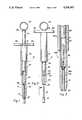
- FIG. 1is a from elevation of the device for applying gutta percha to a carrier according to a preferred embodiment of the present invention, showing a carrier inserted into the dispensing end of the device.
- FIG. 2is a front elevation of the device of FIG. 1 showing the gutta percha coated carrier after it is pushed out of the dispensing end of the device.
- FIG. 3is an enlarged partial front elevation of the device for applying gutta percha to a carrier according to another embodiment of the present invention, showing a gutta percha containing alternate cannula provided with its own cannula plunger.
- FIG. 4is a slightly enlarged front elevation of a plunger removed from the device of FIG. 1.
- FIG. 5is a top plan elevation of the plunger of FIG. 4.
- FIG. 6is a slightly enlarged front elevation of a barrel removed from the device of FIG. 1.
- FIG. 7is a top plan elevation of the barrel of FIG. 6.
- FIG. 8is a left side elevation of the barrel of FIG. 6.
- FIG. 9is a front elevation of a gutta percha containing cannula for use with the device of FIG. 1.
- FIG. 10is a cross-sectional view of the cannula taken along line 10--10 of FIG. 9.
- FIG. 11is a left side elevation of the barrel illustrating insertion of the cannula into the barrel via a side opening provided in the barrel.
- FIG. 12is a left side elevation of the barrel illustrating the cannula being heated after it is inserted into the barrel.
- FIG. 13is a front elevation of a second alternate embodiment of the device for applying gutta percha to a carrier according to the present invention, shown loaded with a cannula of gutta percha.
- FIG. 14is a front elevation of a second alternate barrel removed from the device of FIG. 13 showing the cannula being loaded therein.
- FIG. 15is a top plan view of the second alternate barrel taken along line 15--15 of FIG. 14.
- FIG. 16is a front elevation of a second alternate plunger removed from the device of FIG. 13.
- FIG. 17is a top plan view of the second alternate plunger of FIG. 16.
- FIG. 18is a left side elevation of the second alternate barrel illustrating the cannula being heated after it is loaded into the second alternate barrel.
- FIG. 19is a partial front elevation of the device of FIG. 13, showing a carrier inserted into the dispensing end of the device.
- FIG. 20is the device of FIG. 19, showing the gutta percha coated carrier after it is pushed out of the dispensing end of the device.
- FIGS. 1 and 2there is illustrated a syringe-type device 10 for applying gutta percha 12 or other suitable thermoplastic material (not illustrated) to a carrier 14 according to a preferred embodiment of the present invention.
- the device 10is provided with a barrel 16, illustrated in FIGS. 6, 7, and 8, having a plunger insertion end 18 and an opposite dispensing end 20. Adjacent the plunger insertion end 18, the barrel 16 is provided externally with an insulating sleeve 21 which prevents fingers (not illustrated) from contacting the barrel 16 after the barrel 16 is heated, as will be described more fully hereinafter.
- the plunger insertion end 18is also provided with a pair of outward extending finger tabs 22, one finger tab 22 being provided on either side of the barrel 16.
- a barrel cavity 24communicates between the plunger insertion end 18 and the dispensing end 20. Adjacent the dispensing end 20, the barrel 16 is provided with an opening 26 which communicates with the barrel cavity 24.
- a cannula 28 pre-filled with gutta percha 12inserts into the barrel cavity 24 by way of opening 26.
- the cannula 28is provided with an upper open end 29 and an opposite lower open end 31 and is hollow between the upper and lower open ends 29 and 31.
- the gutta percha 12is pre-filled in the hollow cannula 28 between the upper and lower ends 29 and 31.
- the gutta percha 12is then heated by means of a flame 33 or other suitable heat source (not illustrated) in order to increase the plasticity of the gutta percha 12 in preparation for inserting it into a root canal (not illustrated).
- the device 10is preferably constructed of metal or other suitable material to enable the device to withstand heating of the gutta percha 12 when the cannula 28 is contained therein.
- the device 10is provided with a plunger 34 having an upper end 36 and an opposite lower end 38.
- the upper end 36is provided with a ring 40 which attaches to one end of a cylindrical main body 42 provided on the plunger 34.
- the main body 42attaches by an opposite end to a reduced cylindrical portion 44 which forms the lower end 38.
- the cylindrical main body 42has an outside diameter slightly smaller than an inside diameter of the barrel cavity 24, and the reduced cylindrical portion 44 has an outside diameter slightly smaller than an inside diameter of the cannula 28.
- the lower end 38 of the plunger 34inserts into the barrel cavity 24 at the plunger insertion end 18 of the barrel 16, and the plunger 34 moves downward in the barrel cavity 24 until the lower end 38 touches the heated gutta percha 12 contained within the cannula 28. Movement of the plunger 34 is facilitated by inserting a thumb (not illustrated) into the ring 40 and placing middle and index fingers (not illustrated) of the same hand (not illustrated) as the thumb (not illustrated) under the finger tabs 22 and pressing the fingers (not illustrated) toward the thumb (not illustrated).
- a carrier 14is then inserted into the heated cannula 28 via the dispensing end 20.
- the plunger 34is then pushed downward, thus pushing the carrier 14, which is now coated with gutta percha 12, out of the device 10.
- the carrier 14is then ready for use in a root canal (not illustrated).
- FIG. 3An alternate device 10A is illustrated in FIG. 3. This embodiment is used in conjunction with an alternate cannula 28A which is provided with its own dispensing cannula plunger 46.
- the barrel 16is employed and an alternate plunger 34A is used which is identical to the plunger 34 except that the reduced cylindrical portion 44 is eliminated.
- the alternate cannula 28Ais inserted into the barrel 16 and is heated. Thereafter, the alternate plunger 34A is inserted into the barrel cavity 24 and pushed downward until the alternate plunger 34A engages the dispensing cannula plunger 46. At this point, a carrier 14 is inserted into the heard cannula 28A via the dispensing end 20.
- the alternate plunger 34Ais then pushed downward, thus pushing the dispensing cannula plunger 46 downward through the alternate cannula 28A and pushing the carrier 14, which is now coated with gutta percha 12, out of the alternate device 10A.
- the carrier 14is then ready for use in a root canal (not illustrated).
- a second alternate device 10Bis illustrated in FIGS. 13 through 20.
- This embodimentis provided with an alternate barrel 16B, illustrated in FIGS. 14 and 15.
- the alternate barrel 16Bhas an alternate plunger insertion end 18B and an opposite alternate dispensing end 20B. Adjacent the alternate plunger insertion end 18B, the alternate barrel 16B is provided externally with an alternate insulating sleeve 21B similar to the insulating sleeve 21 described for the first embodiment of the device 10.
- the alternate plunger insertion end 18Bis likewise provided with a pair of outwardly extending alternate finger tabs 22B, one alternate finger tab 22B being provided on either side of the alternate barrel 16B.
- An alternate barrel cavity 24Bcommunicates between the alternate plunger insertion end 18B and the alternate dispensing end 20B.
- the alternate barrel cavity 24Bis provided with an alternate mating reduced diameter section 32B at the alternate dispensing end 20B, with the remaining length of the alternate barrel cavity 24B being uniform in internal diameter.
- a second alternate cannula 28Bpre-filled with gutta percha 12 between its second alternate cannula open upper end 29B and its opposite second alternate cannula lower end 31B, is inserted into the alternate barrel insertion end 18B of the alternate barrel cavity 24B.
- the second alternate cannula 28Bis then pushed toward the alternate dispensing end 20B until the second alternate cannula open lower end 31B extends outward from the alternate dispensing end 20B and the second alternate cannula 28B is secured by an alternate upper lip 30B provided on the second alternate cannula open upper end 29B which seats into the alternate mating reduced diameter section 32B of the alternate barrel cavity 24B.
- the gutta percha 12is heated by means of the flame 33 or other suitable heat source (not illustrated) in order to increase the plasticity of the gutta percha 12 in preparation for inserting a carrier 14 into the second alternate cannula 28B.
- the second alternate device 10Balthough not directly heated by the flame 33 in this embodiment, is preferably constructed of metal or other suitable material to enable the second alternate device 10B to withstand heat transferred to it by means of the attached alternate cannula 28B as it is heated.
- the second alternate device 10Bis provided with a second alternate plunger 34B having an alternate upper end 36B and an opposite alternate lower end 38B.
- the alternate upper end 36Bis provided with an alternate ring 40B which attaches to one end of an alternate cylindrical main body 42B provided on the second alternate plunger 34B.
- the alternate cylindrical main body 42Battaches by an opposite end to an alternate reduced cylindrical portion 44B which forms the alternate lower end 38B.
- the alternate cylindrical main body 42Bhas an outside diameter smaller than an inside diameter of the alternate barrel cavity 24B, and the alternate reduced cylindrical portion 44B has an outside diameter slightly smaller than an inside diameter of the second alternate cannula 28B.
- the alternate cylindrical main body 42Bis provided with circumferential groove 48 therearound into which an O-ring 50 inserts. As the alternate cylindrical main body 42B is pushed through the alternate barrel cavity 24B and the alternate reduced cylindrical portion 44B is simultaneously pushed through the second alternate cannula 28B, the O-ring 50 movably engages the alternate barrel cavity 24B.
- the purpose of the O-ring 50is to provide frictional resistance to movement of the second alternate plunger 34B within the alternate barrel 16B and thereby enabling the user to more precisely control movement of the second alternate plunger 34B.
- the second alternate plunger 34Bis inserted into the alternate barrel 16B at the alternate plunger insertion end 18B and is moved downward into the alternate barrel cavity 24B until the alternate lower end 38B touches the heated gutta percha 12 contained with the second alternate cannula 28B. Movement of the second alternate plunger 34B is facilitated by inserting a thumb (not illustrated) into the alternate ring 40B and placing middle and index fingers (not illustrated) of the same hand (not illustrated) as the thumb (not illustrated) under the alternate finger tabs 22B and pressing the fingers (not illustrated) toward the thumb (not illustrated).
- the carrier 14is then inserted into the heated second alternate cannula 28B via the second alternate cannula open lower end 31B.
- the second alternate plunger 34Bis then pushed downward, thus pushing the carrier 14, which is now coated with gutta percha 12, out of the second alternate device 10B.
- the coated carrier 14is then ready for use in a root canal (not illustrated).
- the second alternate device 10Bmay be employed with the alternate cannula 28A, shown in FIG. 3. This may be done by either using the alternate reduced cylindrical portion 44B to engage the dispensing cannula plunger 46 or, alternately, by modifying the second alternate plunger 34B so as to eliminate the alternate reduced cylindrical portion 44B. If the alternate reduced cylindrical portion 44B is eliminated, the alternate cylindrical main body 42B serves as the alternate lower end 38B of the second alternate plunger 34B which is engagable with the dispensing cannula plunger 46.
Landscapes
- Health & Medical Sciences (AREA)
- Veterinary Medicine (AREA)
- Oral & Maxillofacial Surgery (AREA)
- Epidemiology (AREA)
- Life Sciences & Earth Sciences (AREA)
- Animal Behavior & Ethology (AREA)
- General Health & Medical Sciences (AREA)
- Dentistry (AREA)
- Public Health (AREA)
- Dental Tools And Instruments Or Auxiliary Dental Instruments (AREA)
- Processes Specially Adapted For Manufacturing Cables (AREA)
- Food-Manufacturing Devices (AREA)
- Adornments (AREA)
- Toys (AREA)
- Audible-Bandwidth Dynamoelectric Transducers Other Than Pickups (AREA)
- Crystals, And After-Treatments Of Crystals (AREA)
- Manufacture Of Motors, Generators (AREA)
Abstract
Description
Claims (23)
Priority Applications (7)
| Application Number | Priority Date | Filing Date | Title |
|---|---|---|---|
| US08/048,432US5328367A (en) | 1993-04-14 | 1993-04-14 | Method and apparatus for applying gutta percha to a carrier |
| CA002119603ACA2119603C (en) | 1993-04-14 | 1994-03-22 | Method of applying gutta percha to a carrier |
| DK94302556TDK0619987T3 (en) | 1993-04-14 | 1994-04-12 | Improved method of applying a supporting element gutta percha |
| AT94302556TATE183912T1 (en) | 1993-04-14 | 1994-04-12 | METHOD FOR APPLYING ''GUTTA PERCHA'' TO A BASE |
| JP6073284AJPH06304182A (en) | 1993-04-14 | 1994-04-12 | Method of attaching gutta-percha to carrier |
| EP94302556AEP0619987B1 (en) | 1993-04-14 | 1994-04-12 | Improved method of applying gutta percha to a carrier |
| DE69420300TDE69420300T2 (en) | 1993-04-14 | 1994-04-12 | Procedure to apply "Gutta Percha" to a base |
Applications Claiming Priority (1)
| Application Number | Priority Date | Filing Date | Title |
|---|---|---|---|
| US08/048,432US5328367A (en) | 1993-04-14 | 1993-04-14 | Method and apparatus for applying gutta percha to a carrier |
Publications (1)
| Publication Number | Publication Date |
|---|---|
| US5328367Atrue US5328367A (en) | 1994-07-12 |
Family
ID=21954544
Family Applications (1)
| Application Number | Title | Priority Date | Filing Date |
|---|---|---|---|
| US08/048,432Expired - LifetimeUS5328367A (en) | 1993-04-14 | 1993-04-14 | Method and apparatus for applying gutta percha to a carrier |
Country Status (7)
| Country | Link |
|---|---|
| US (1) | US5328367A (en) |
| EP (1) | EP0619987B1 (en) |
| JP (1) | JPH06304182A (en) |
| AT (1) | ATE183912T1 (en) |
| CA (1) | CA2119603C (en) |
| DE (1) | DE69420300T2 (en) |
| DK (1) | DK0619987T3 (en) |
Cited By (23)
| Publication number | Priority date | Publication date | Assignee | Title |
|---|---|---|---|---|
| FR2797174A1 (en)* | 1999-08-04 | 2001-02-09 | Micro Mega Sa | CANALAR SHUTTERING METHOD AND DEVICE FOR PROVIDING THE SHUTTER PRODUCT |
| FR2814938A1 (en)* | 2000-10-11 | 2002-04-12 | Francis Carrere | Process of filling and sealing of dental canal, uses syringe-shaped distributing device provided with means of heating, expulsion and compacting of thermoplastic material |
| US6447297B1 (en) | 1999-05-12 | 2002-09-10 | Jeneric/Pentron, Inc. | Endodontic post system |
| US20030113686A1 (en)* | 2001-10-24 | 2003-06-19 | Weitao Jia | Root canal filling material |
| US20030219699A1 (en)* | 2002-05-22 | 2003-11-27 | Howard Martin | Stepped root canal plugger |
| US20040115589A1 (en)* | 2002-12-13 | 2004-06-17 | Ajit Karmaker | Endodontic obturator |
| US20050048435A1 (en)* | 1999-08-04 | 2005-03-03 | Jean-Marie Badoz | Canal filling method and device for providing the filling product |
| US7086864B2 (en) | 1999-05-12 | 2006-08-08 | Pentron Clinical Technologies, Llc | Endodontic post system |
| US7163401B2 (en) | 1999-05-12 | 2007-01-16 | Pentron Clinical Technologies, Llc | Endodontic post and obturating system |
| US7168952B2 (en) | 1999-05-12 | 2007-01-30 | Pentron Clinical Technologies, Llc | Endodontic post and obturating system |
| US7204875B2 (en) | 2001-10-24 | 2007-04-17 | Pentron Clinical Technologies, Llc | Dental filling material |
| US7211136B2 (en) | 2001-10-24 | 2007-05-01 | Pentron Clinical Technologies, Llc | Dental filling material |
| US7303817B2 (en) | 2001-10-24 | 2007-12-04 | Weitao Jia | Dental filling material |
| US20080241799A1 (en)* | 2007-03-26 | 2008-10-02 | Ultradent Products, Inc. | Kits and methods for chair-side coating of endodontic cones |
| WO2008120018A1 (en)* | 2007-03-30 | 2008-10-09 | Alastair Macdonald | Method and apparatus for obturating the coronal aspect of a root canal |
| US20090142728A1 (en)* | 2007-12-04 | 2009-06-04 | Lawter James R | Actuators for device for delivering medicinal implants |
| US20090148500A1 (en)* | 2007-12-04 | 2009-06-11 | Lawter James R | Medicinal implant cartridge |
| US7699609B2 (en) | 2002-03-29 | 2010-04-20 | Orapharma, Inc. | Dispensing apparatus and cartridge with deformable tip |
| US20100124728A1 (en)* | 2008-11-19 | 2010-05-20 | Harmeet Walia | Device and method for in canal gutta-percha heating and condensation |
| US20100136502A1 (en)* | 2008-12-02 | 2010-06-03 | Zhangwen Wu | Medicinal implant device and cartridge |
| US7750063B2 (en) | 2001-10-24 | 2010-07-06 | Pentron Clinical Technologies, Llc | Dental filling material |
| US7976489B2 (en) | 2007-12-04 | 2011-07-12 | Orapharma, Inc. | Device for delivering medicinal implants |
| US20180085196A1 (en)* | 2016-09-11 | 2018-03-29 | Tulsa Dental Products Llc | System for providing endodontic material using induction heating |
Families Citing this family (4)
| Publication number | Priority date | Publication date | Assignee | Title |
|---|---|---|---|---|
| US7942673B2 (en)* | 2003-09-05 | 2011-05-17 | Buchanan L Stephen | Dental obturator |
| DE102005054232A1 (en)* | 2005-11-14 | 2007-05-16 | Coltene Whaledent Gmbh & Co Kg | Obturation device for blocking an apical opening of a root canal of a tooth |
| JP5384876B2 (en)* | 2008-08-21 | 2014-01-08 | 向笠 雅夫 | Root canal filling device and method of using the same |
| KR101586612B1 (en)* | 2015-08-17 | 2016-01-19 | 비엔엘바이오테크 주식회사 | Dispenser device for dental material |
Citations (15)
| Publication number | Priority date | Publication date | Assignee | Title |
|---|---|---|---|---|
| US3581399A (en)* | 1969-08-08 | 1971-06-01 | Centrix Inc | Composite resin filling syringe and technique |
| US4684344A (en)* | 1986-04-11 | 1987-08-04 | Nalge Company | Electrically powered and heated endodontic syringe |
| US4746292A (en)* | 1987-04-02 | 1988-05-24 | Johnson William B | Tool and method for removing a parted endodontic file |
| US4758156A (en)* | 1987-04-02 | 1988-07-19 | Johnson William B | Tool for use in applying filler material to an endodontically prepared root canal |
| US4892481A (en)* | 1987-04-07 | 1990-01-09 | Dentsply Research & Development Corp. | Dental composite carrier and composite package |
| US4894011A (en)* | 1988-11-02 | 1990-01-16 | Johnson William B | Appliance for use in applying filler material to an endodontically prepared root canal |
| US5067900A (en)* | 1991-01-08 | 1991-11-26 | Mcspadden John T | Apparatus and method for applying gutta-percha to a carrier |
| US5085586A (en)* | 1990-08-28 | 1992-02-04 | Johnson William B | Method and apparatus for installing a post in a tooth having an existing endodontic obturator therein |
| US5089183A (en)* | 1991-01-09 | 1992-02-18 | Johnson William B | Method of manufacturing appliances for use in filling endodontically prepared root canals |
| US5098298A (en)* | 1991-04-18 | 1992-03-24 | Johnson William B | Appliance and method of use for filling an endodontically prepared root canal |
| US5118297A (en)* | 1991-01-09 | 1992-06-02 | Johnson William B | Obturator body for use in filling an endontically prepared root |
| US5149268A (en)* | 1991-04-16 | 1992-09-22 | Johnson William B | Method of filling an endodontically prepared root canal |
| US5161973A (en)* | 1990-08-28 | 1992-11-10 | Johnson William B | Tubular dental post |
| US5190702A (en)* | 1991-01-09 | 1993-03-02 | Johnson William B | Method of making a mold for manufacturing dental appliances |
| US5215461A (en)* | 1991-03-22 | 1993-06-01 | John Riazi | Endodontic appliance and related method |
Family Cites Families (5)
| Publication number | Priority date | Publication date | Assignee | Title |
|---|---|---|---|---|
| US1789766A (en)* | 1925-07-30 | 1931-01-20 | Radium Emanation Corp | Surgical instrument for implanting capillary seeds containing radium emanation |
| US2907327A (en)* | 1957-02-08 | 1959-10-06 | Pfizer & Co C | Pellet implanter |
| US3744493A (en)* | 1972-01-10 | 1973-07-10 | Syntex Corp | Implanter having an improved cartridge ejector |
| US4553935A (en)* | 1983-12-20 | 1985-11-19 | Kyocera Corporation | Apparatus for waxing-up |
| US5286193A (en)* | 1991-10-30 | 1994-02-15 | Roane James B | Endodontic gutta percha placement |
- 1993
- 1993-04-14USUS08/048,432patent/US5328367A/ennot_activeExpired - Lifetime
- 1994
- 1994-03-22CACA002119603Apatent/CA2119603C/ennot_activeExpired - Lifetime
- 1994-04-12JPJP6073284Apatent/JPH06304182A/enactivePending
- 1994-04-12DKDK94302556Tpatent/DK0619987T3/enactive
- 1994-04-12DEDE69420300Tpatent/DE69420300T2/ennot_activeExpired - Lifetime
- 1994-04-12EPEP94302556Apatent/EP0619987B1/ennot_activeExpired - Lifetime
- 1994-04-12ATAT94302556Tpatent/ATE183912T1/ennot_activeIP Right Cessation
Patent Citations (15)
| Publication number | Priority date | Publication date | Assignee | Title |
|---|---|---|---|---|
| US3581399A (en)* | 1969-08-08 | 1971-06-01 | Centrix Inc | Composite resin filling syringe and technique |
| US4684344A (en)* | 1986-04-11 | 1987-08-04 | Nalge Company | Electrically powered and heated endodontic syringe |
| US4746292A (en)* | 1987-04-02 | 1988-05-24 | Johnson William B | Tool and method for removing a parted endodontic file |
| US4758156A (en)* | 1987-04-02 | 1988-07-19 | Johnson William B | Tool for use in applying filler material to an endodontically prepared root canal |
| US4892481A (en)* | 1987-04-07 | 1990-01-09 | Dentsply Research & Development Corp. | Dental composite carrier and composite package |
| US4894011A (en)* | 1988-11-02 | 1990-01-16 | Johnson William B | Appliance for use in applying filler material to an endodontically prepared root canal |
| US5161973A (en)* | 1990-08-28 | 1992-11-10 | Johnson William B | Tubular dental post |
| US5085586A (en)* | 1990-08-28 | 1992-02-04 | Johnson William B | Method and apparatus for installing a post in a tooth having an existing endodontic obturator therein |
| US5067900A (en)* | 1991-01-08 | 1991-11-26 | Mcspadden John T | Apparatus and method for applying gutta-percha to a carrier |
| US5118297A (en)* | 1991-01-09 | 1992-06-02 | Johnson William B | Obturator body for use in filling an endontically prepared root |
| US5089183A (en)* | 1991-01-09 | 1992-02-18 | Johnson William B | Method of manufacturing appliances for use in filling endodontically prepared root canals |
| US5190702A (en)* | 1991-01-09 | 1993-03-02 | Johnson William B | Method of making a mold for manufacturing dental appliances |
| US5215461A (en)* | 1991-03-22 | 1993-06-01 | John Riazi | Endodontic appliance and related method |
| US5149268A (en)* | 1991-04-16 | 1992-09-22 | Johnson William B | Method of filling an endodontically prepared root canal |
| US5098298A (en)* | 1991-04-18 | 1992-03-24 | Johnson William B | Appliance and method of use for filling an endodontically prepared root canal |
Cited By (37)
| Publication number | Priority date | Publication date | Assignee | Title |
|---|---|---|---|---|
| US7086864B2 (en) | 1999-05-12 | 2006-08-08 | Pentron Clinical Technologies, Llc | Endodontic post system |
| US6447297B1 (en) | 1999-05-12 | 2002-09-10 | Jeneric/Pentron, Inc. | Endodontic post system |
| US7168952B2 (en) | 1999-05-12 | 2007-01-30 | Pentron Clinical Technologies, Llc | Endodontic post and obturating system |
| US7163401B2 (en) | 1999-05-12 | 2007-01-16 | Pentron Clinical Technologies, Llc | Endodontic post and obturating system |
| WO2001010331A1 (en)* | 1999-08-04 | 2001-02-15 | Micro-Mega (Societe Anonyme) | Canal filling method and device for providing the filling product |
| FR2797174A1 (en)* | 1999-08-04 | 2001-02-09 | Micro Mega Sa | CANALAR SHUTTERING METHOD AND DEVICE FOR PROVIDING THE SHUTTER PRODUCT |
| US20050048435A1 (en)* | 1999-08-04 | 2005-03-03 | Jean-Marie Badoz | Canal filling method and device for providing the filling product |
| FR2814938A1 (en)* | 2000-10-11 | 2002-04-12 | Francis Carrere | Process of filling and sealing of dental canal, uses syringe-shaped distributing device provided with means of heating, expulsion and compacting of thermoplastic material |
| EP1197187A3 (en)* | 2000-10-11 | 2002-06-05 | Francis Carrere | Process and device for the obturation and sealing of a dental root canal |
| US7837471B2 (en) | 2001-10-24 | 2010-11-23 | Pentron Clinical Technologies, Llc | Dental filling materials and methods of use |
| US7750063B2 (en) | 2001-10-24 | 2010-07-06 | Pentron Clinical Technologies, Llc | Dental filling material |
| US9492360B2 (en) | 2001-10-24 | 2016-11-15 | Pentron Clinical Technologies, Llc | Endodontic post and obturator |
| US7204874B2 (en) | 2001-10-24 | 2007-04-17 | Pentron Clinical Technologies, Llc | Root canal filling material |
| US7204875B2 (en) | 2001-10-24 | 2007-04-17 | Pentron Clinical Technologies, Llc | Dental filling material |
| US7211136B2 (en) | 2001-10-24 | 2007-05-01 | Pentron Clinical Technologies, Llc | Dental filling material |
| US20030113686A1 (en)* | 2001-10-24 | 2003-06-19 | Weitao Jia | Root canal filling material |
| US7303817B2 (en) | 2001-10-24 | 2007-12-04 | Weitao Jia | Dental filling material |
| US7699609B2 (en) | 2002-03-29 | 2010-04-20 | Orapharma, Inc. | Dispensing apparatus and cartridge with deformable tip |
| US20030219699A1 (en)* | 2002-05-22 | 2003-11-27 | Howard Martin | Stepped root canal plugger |
| US20040115589A1 (en)* | 2002-12-13 | 2004-06-17 | Ajit Karmaker | Endodontic obturator |
| US7252508B2 (en) | 2002-12-13 | 2007-08-07 | Pentron Clinical Technologies, Llc | Endodontic obturator |
| US7833015B2 (en)* | 2007-03-26 | 2010-11-16 | Ultradent Products, Inc. | Kits and methods for chair-side coating of endodontic cones |
| US20080241799A1 (en)* | 2007-03-26 | 2008-10-02 | Ultradent Products, Inc. | Kits and methods for chair-side coating of endodontic cones |
| US20080286723A1 (en)* | 2007-03-26 | 2008-11-20 | Ultradent Products, Inc. | Methods for chair-side coating of endodontic cones |
| WO2008120018A1 (en)* | 2007-03-30 | 2008-10-09 | Alastair Macdonald | Method and apparatus for obturating the coronal aspect of a root canal |
| US7976489B2 (en) | 2007-12-04 | 2011-07-12 | Orapharma, Inc. | Device for delivering medicinal implants |
| US20090142728A1 (en)* | 2007-12-04 | 2009-06-04 | Lawter James R | Actuators for device for delivering medicinal implants |
| US20090148500A1 (en)* | 2007-12-04 | 2009-06-11 | Lawter James R | Medicinal implant cartridge |
| US7976491B2 (en) | 2007-12-04 | 2011-07-12 | Orapharma, Inc. | Actuators for device for delivering medicinal implants |
| US7976490B2 (en) | 2007-12-04 | 2011-07-12 | Orapharma, Inc. | Medicinal implant cartridge |
| US8480615B2 (en) | 2007-12-04 | 2013-07-09 | Orapharma, Inc. | Device for delivering medicinal implants |
| US20100124728A1 (en)* | 2008-11-19 | 2010-05-20 | Harmeet Walia | Device and method for in canal gutta-percha heating and condensation |
| US20100136502A1 (en)* | 2008-12-02 | 2010-06-03 | Zhangwen Wu | Medicinal implant device and cartridge |
| US8048021B2 (en) | 2008-12-02 | 2011-11-01 | Orapharma, Inc. | Medicinal implant device and cartridge |
| US9566141B2 (en) | 2008-12-02 | 2017-02-14 | Orapharma, Inc. | Medicinal implant device and cartridge |
| US20180085196A1 (en)* | 2016-09-11 | 2018-03-29 | Tulsa Dental Products Llc | System for providing endodontic material using induction heating |
| US10881485B2 (en)* | 2016-09-11 | 2021-01-05 | Dentsply Sirona Inc. | System for providing endodontic material using induction heating |
Also Published As
| Publication number | Publication date |
|---|---|
| ATE183912T1 (en) | 1999-09-15 |
| CA2119603C (en) | 2004-08-24 |
| DE69420300D1 (en) | 1999-10-07 |
| EP0619987A3 (en) | 1995-03-01 |
| JPH06304182A (en) | 1994-11-01 |
| CA2119603A1 (en) | 1994-10-15 |
| EP0619987B1 (en) | 1999-09-01 |
| DK0619987T3 (en) | 2000-03-27 |
| DE69420300T2 (en) | 1999-12-30 |
| EP0619987A2 (en) | 1994-10-19 |
Similar Documents
| Publication | Publication Date | Title |
|---|---|---|
| US5328367A (en) | Method and apparatus for applying gutta percha to a carrier | |
| EP0522130B1 (en) | Apparatus and method for applying gutta-percha | |
| US5215461A (en) | Endodontic appliance and related method | |
| CA2080704C (en) | Endodontic gutta percha placement | |
| US5098298A (en) | Appliance and method of use for filling an endodontically prepared root canal | |
| US5697903A (en) | Methods and apparatus for dispensing compositions | |
| US4758156A (en) | Tool for use in applying filler material to an endodontically prepared root canal | |
| US11471249B2 (en) | Self-heating electric plugger/syringe needle for use in filling a root canal | |
| US6283946B1 (en) | Long stem syringe apparatus for dispensing compositions and related methods | |
| US4681545A (en) | Method for rapid obturation of root canals | |
| US20070031794A1 (en) | Apparatus and method for root canal obturation | |
| Marlin et al. | Clinical use of injection-molded thermoplasticized gutta-percha for obturation of the root canal system: a preliminary report | |
| Carrotte | Endodontics: Part 8 Filling the root canal system | |
| US7008222B2 (en) | Root canal plugging apparatus for dental work | |
| WO1989012428A1 (en) | Dental agent applicator | |
| EP0337024B1 (en) | Tool for use in applying filler material to an endodontically prepared root canal | |
| CA1302129C (en) | Tool for use in applying filler material to an endodontically prepared root canal | |
| EP0148239A1 (en) | A method and apparatus for rapid obturation of root canals | |
| FR2814938A1 (en) | Process of filling and sealing of dental canal, uses syringe-shaped distributing device provided with means of heating, expulsion and compacting of thermoplastic material |
Legal Events
| Date | Code | Title | Description |
|---|---|---|---|
| FEPP | Fee payment procedure | Free format text:PAYOR NUMBER ASSIGNED (ORIGINAL EVENT CODE: ASPN); ENTITY STATUS OF PATENT OWNER: LARGE ENTITY | |
| AS | Assignment | Owner name:DENTSPLY RESEARCH & DEVELOPMENT CORP., DELAWARE Free format text:ASSIGNMENT OF ASSIGNORS INTEREST;ASSIGNOR:TULSA DENTAL PRODUCTS, INC.;REEL/FRAME:007980/0087 Effective date:19960108 | |
| AS | Assignment | Owner name:DENTSPLY INTERNATIONAL INC., PENNSYLVANIA Free format text:ASSIGNMENT OF ASSIGNORS INTEREST;ASSIGNOR:DENTSPLY RESEARCH & DEVELOPMENT CORP.;REEL/FRAME:007978/0639 Effective date:19960522 | |
| FP | Lapsed due to failure to pay maintenance fee | Effective date:19980715 | |
| FEPP | Fee payment procedure | Free format text:PETITION RELATED TO MAINTENANCE FEES FILED (ORIGINAL EVENT CODE: PMFP); ENTITY STATUS OF PATENT OWNER: LARGE ENTITY | |
| FEPP | Fee payment procedure | Free format text:PETITION RELATED TO MAINTENANCE FEES GRANTED (ORIGINAL EVENT CODE: PMFG); ENTITY STATUS OF PATENT OWNER: LARGE ENTITY | |
| FPAY | Fee payment | Year of fee payment:4 | |
| SULP | Surcharge for late payment | ||
| AS | Assignment | Owner name:TULSA DENTAL PRODUCTS INC., OKLAHOMA Free format text:ASSIGNMENT OF ASSIGNORS INTEREST;ASSIGNORS:TULSA DENTAL PRODUCTS, L.L.C.;QUALITY DENTAL PRODUCTS, INC.;TDP, INC.;AND OTHERS;REEL/FRAME:010095/0358 Effective date:19960108 | |
| REMI | Maintenance fee reminder mailed | ||
| FPAY | Fee payment | Year of fee payment:8 | |
| FP | Lapsed due to failure to pay maintenance fee | Effective date:20020712 | |
| STCF | Information on status: patent grant | Free format text:PATENTED CASE | |
| FEPP | Fee payment procedure | Free format text:PAT HOLDER NO LONGER CLAIMS SMALL ENTITY STATUS, ENTITY STATUS SET TO UNDISCOUNTED (ORIGINAL EVENT CODE: STOL); ENTITY STATUS OF PATENT OWNER: LARGE ENTITY | |
| REMI | Maintenance fee reminder mailed | ||
| FPAY | Fee payment | Year of fee payment:12 |