US5327493A - Device for detecting tones on telephone lines - Google Patents
Device for detecting tones on telephone linesDownload PDFInfo
- Publication number
- US5327493A US5327493AUS07/694,697US69469791AUS5327493AUS 5327493 AUS5327493 AUS 5327493AUS 69469791 AUS69469791 AUS 69469791AUS 5327493 AUS5327493 AUS 5327493A
- Authority
- US
- United States
- Prior art keywords
- line
- tone
- telephone
- hook
- capacitor
- Prior art date
- Legal status (The legal status is an assumption and is not a legal conclusion. Google has not performed a legal analysis and makes no representation as to the accuracy of the status listed.)
- Expired - Lifetime
Links
Images


Classifications
- H—ELECTRICITY
- H04—ELECTRIC COMMUNICATION TECHNIQUE
- H04M—TELEPHONIC COMMUNICATION
- H04M3/00—Automatic or semi-automatic exchanges
- H04M3/42—Systems providing special services or facilities to subscribers
- H04M3/50—Centralised arrangements for answering calls; Centralised arrangements for recording messages for absent or busy subscribers ; Centralised arrangements for recording messages
- H04M3/53—Centralised arrangements for recording incoming messages, i.e. mailbox systems
- H04M3/537—Arrangements for indicating the presence of a recorded message, whereby the presence information might include a preview or summary of the message
- H—ELECTRICITY
- H04—ELECTRIC COMMUNICATION TECHNIQUE
- H04M—TELEPHONIC COMMUNICATION
- H04M1/00—Substation equipment, e.g. for use by subscribers
- H04M1/82—Line monitoring circuits for call progress or status discrimination
- H—ELECTRICITY
- H04—ELECTRIC COMMUNICATION TECHNIQUE
- H04M—TELEPHONIC COMMUNICATION
- H04M2201/00—Electronic components, circuits, software, systems or apparatus used in telephone systems
- H04M2201/38—Displays
Definitions
- the present inventionrelates to the detection of call progress signaling tones on telephone lines, primarily in user telephone equipment but also in other telephone equipment such as central office or PBX equipment.
- Telephone systemsuse recognizable call progress tones to indicate to the listener the status of a component of the system. Examples include: dial tone, busy tone, reorder tone, and ringback tone.
- the dial toneis a steady tone and the other three employ an on-off cadence. These tones are made to sound sufficiently different to the listener that the listener can distinguish one from another.
- the signaling tones described aboveare all intended for communicating with a human user of the telephone system. As originally conceived, they all require that the user be capable of hearing and distinguishing the various tones. However, in some telephone system equipment it is desired that call progress tones be detected by a device connected to the telephone line which device then causes other actions. For example, various items of telephone system equipment, such as central office switches and PBX switches, can handle additional sophisticated functions for customers if they can recognize and distinguish the various tones. Various methods of distinguishing distinctive tones are known in the art. For example, U.S. Pat. No. 4,935,958 issued to S. Morganstein on Jun.
- Message Waiting Indication--VisualWhen a message is waiting for a telephone system customer, this feature illuminates an indicator light on the customer's telephone equipment.
- This systemrequires special equipment at the central office which can send a special electronic signal to the customer's telephone equipment and special customer equipment which can receive and interpret the signal and turn on the indicator light.
- This designhas substantial limitations including: (1) cost, (2) incompatibility with the audible message waiting indication so one cannot determine whether a message is waiting by lifting the hand set of an extension telephone, (3) incompatibility with certain other telephone system features, and (4) loss of the visual message waiting indication signal if the customer's telephone is "off-hook" for 2 -1/2 hours or more when the signal is sent.
- Special customer premises telephone equipmentsuch as the message waiting indication device described above, typically requires electrical power to perform the additional features. If the power requirements are low and are needed only when the telephone is "off-hook” the power can be obtained from the loop current supplied by the central office. However, various features, such as the indicator light described above, require power when the telephone is "on-hook". In these situations, power is obtained from batteries which must be periodically replaced or from a plug connected to a standard AC wall outlet.
- One aspect of the disclosed inventionis the conversion of auditory telephone tones to visual indications.
- An embodiment of this inventionilluminates a visual indication light on a device connected to the customer's telephone line when there is an auditory message waiting indication in the form of a non-standard dial tone placed on the customer's line by the central office.
- This embodiment of the inventionovercomes the short comings of the current message waiting indication--visual systems described above. It is far less expensive--the message waiting indication detector and indicator light can be added to the customer's telephone equipment without replacing existing equipment and no additional equipment is required at the central office. The auditory message waiting indication can still be heard at all extension telephones. The addition of this device at the customer premises does not interfere with any other features offered by the central office. The customer's telephone can be "off-hook" for any number of hours and the message waiting indication signal will not be lost.
- a distinctive non-standard dial toneis used to indicate to a telephone system customer that the customer can retrieve a message by dialing a special number, as described above, the customer must periodically lift the hand set of the telephone and listen for the distinctive tone. This invention eliminates the need for the customer to lift the hand set and to remember to check for messages.
- Another embodiment of this aspect of the inventionis the enhancement of telephone communication systems for the deaf and certain similar uses. Facsimile transmission and character transmission by modem are effective means for the deaf to use telephone systems for communications. However, the inability to hear dial tones, ringback tones, and busy tones make the telephone network difficult for deaf people to use. According to the present invention, these tones, and others, are converted to visual indications to facilitate use of the system by deaf people and by people working in noisy environments.
- a usercan place telephone calls without an auditory interruption, such as when they are engaged in verbal communications with another party in person or by telephone.
- the visual indicationmight take the form of an indicator light, certain characters or symbols on a display, or mechanical flags which change position.
- Another aspect of the inventionis a novel method of detecting a non-standard dial tone.
- An embodiment of this aspect of the inventionautomatically goes "off-hook” and determines whether a distinctive predetermined tone is present on the line.
- Central offices or PBX systemscan use a distinctive, non-standard dial tone to indicate to a telephone user a special status, such as a message waiting.
- Existing systemssuch as described above, will send a special signal, not intended to be distinguished by the human ear, to a special user telephone which can receive the signal and illuminate an indicator light on the telephone.
- no special signalis required from the central office or PBX.
- the invented deviceautomatically and periodically goes "off-hook", listens for a dial tone and determines whether it is the special dial tone.
- the turning on of the indicator lightmight be delayed by no more than the period of time between each automatic going off-hook and checking for the special tone.
- An alternative embodiment of this aspect of the inventionalso allows the message waiting indicator device to automatically go off-hook soon after each use of the line to see if a message was left while the line was busy.
- a further embodimentalso goes off-hook to check the dial tone within a short period of time after each ring with no answer in case the calling party chose to leave a message.
- Another embodiment of an aspect of the inventioncan be used in alarm systems.
- Many premises alarm systemsare connected to a standard telephone line and configured to automatically dial a certain telephone number when certain alarm triggering events occur.
- This featureis defeated, without an alarm or notice to the user of the premises, if the telephone line leading from the premises is cut or otherwise interrupted.
- the prior art solution to this problemuses a dedicated telephone line and includes a detector in the premises equipment which detects when the line is cut and signals accordingly. If the present invention is added to the premises equipment, the premises equipment can periodically, automatically go "off-hook” and check for a dial tone. If the dial tone is not present, it can then sound an alarm or notify the user of the premises that the line is not operational.
- This embodiment of the inventionwill allow the use of a regular telephone line which is much less expensive than a dedicated telephone line. And the regular line can also be used for standard telephone service since the system does not need to be checking for integrity of the line when the line is in use.
- the inventioncan be configured to take any of many actions when a distinctive, predetermined tone is detected on the line. It can trigger a device which plays an auditory message for anyone who is listening; it can turn on a continuous bell or buzzer; it can move the position of a flag; it can turn on an indicator light; it can present characters or symbols on a display.
- Still another aspect of the inventionis a novel design of an electronic circuit which can be configured to detect interruptions in a signal, such as the stuttered dial tone, the busy tone, the ringback tone, the reorder tone, and other tones not used in the telephone system.
- An alternative embodimentcan detect many such tones and distinguish between them and can identify a lack of interruptions as a standard dial tone.
- This aspectcan be employed whenever interruptions of a predetermined minimum duration are to be detected, whether or not the duration of the on period or the off period is regular.
- This aspect of the inventioncan also be embodied in devices which detect interruptions in a flow of energy other than electricity, such as pneumatics, hydraulics, or optics.
- the novel circuitemploys a limiter, such as an amplifier or diode, and an RC circuit in combination with a Schmitt trigger.
- the resistor-capacitor circuiteffectively averages the signal output so that, when the signal is present, the capacitor is, on the average, discharging or kept empty (or, in an alternative embodiment, charging or kept full) and when no signal is present, the capacitor is in the opposite state.
- This circuitcan be tuned to detect interruptions that are as short as one or two cycles of the lowest AC frequency that is to be considered a steady "on" in the cadence.
- the Schmitt triggeris configured to flop when the capacitor's charge passes a threshold, and a counter counts the flops.
- the counteris configured to count flops during a particular period of time.
- the on-off cadence of the toneeffects a corresponding high-low voltage cadence in the capacitor, which, in turn, produces a series of high-low pulses in the Schmitt trigger that are counted by a counter.
- a logic circuit or microprocessordetermines whether a particular tone is detected by comparing the count to a predetermined number. In the alternative embodiment which can distinguish between the various call progress tones, the number of pulses is compared to a set of values to determine which tone is present.
- This aspect of the inventionpresents numerous advantages over the prior art.
- the novel circuitis broadly tolerant of variations in the on duration and the off duration, allowing it to correctly identify the call progress tones even if their cadences are irregular or differ from the norm.
- telephone network regulationslimit the amount of power that can be drawn from the network by customer premises equipment in an on-hook state to about 230 microwatts. This is not enough power to illuminate an indicator light or run logic circuits.
- the equipmentis off-hook, between 96 milliwatts and 1.53 watts of power is available from the network, which is more than enough to power devices such as the present invention.
- a further aspect of the present inventionautomatically goes off-hook periodically to gain power which stores in an energy storage device. The stored energy is then used to run the equipment while it is in the on-hook state. This eliminates the need to power the device from standard AC current or batteries which require replacement.
- the energy storage devicecan be either a large capacitor or a rechargeable battery.
- a customer premises devicewhich automatically goes off hook periodically, checks for a stuttered dial tone, and if one is found, illuminates a visual indicator light.
- FIG. 1is a block diagram showing the components of the preferred embodiment and the relationships between them.
- FIG. 2shows the timing counter which takes the 9 Hertz clock signal and creates from it timing pulses of various durations.
- FIG. 3shows the central logic to which the outputs of all the other circuits connect.
- FIG. 4shows two elements of the line interface: the ring or loop detector and the hook switch.
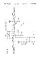
- FIG. 5shows the third element of the line interface: the tone detector circuit.
- FIG. 6shows a capacitor power supply which is an alternative to the battery power supply assumed in FIG. 4.
- FIG. 1is a block diagram showing the five basic functional blocks of the stutter dial tone indicator: system clock 100, timing generator 200, logic block 300, telephone line interface 400, and power supply 500.
- the system clock 100should be of relatively low frequency, on the order of 10 Hz, to limit power requirements, and should be fairly insensitive to power supply fluctuation. This allows use of either batteries or a power storage capacitor as the power supply 500 to keep the bulk and cost of the unit to a minimum.
- FIG. 2shows timing generator 200 consisting of binary counter 202, which takes the clock signal and divides it by powers of two to derive the basic timing functions used by the logic.
- a window timer(approximately 1.75 seconds) is used to determine how long to go off-hook to look for stutter dial tone.
- a reset timer(approximately 3.55 seconds) is used to reset timing generator 200 and to generate a signal that the unit has checked once for stutter dial tone.
- a short timer(approximately 3.75 minutes) is used for checking for stutter dial tone after each ring-no-answer call or off-hook by the telephone.
- a long timer(approximately 15 minutes) is used for periodic checking to see if the state of stutter dial tone has changed without any activity at the telephone, such as by the user receiving messages from another phone.
- the timers usedare examples only and each could be changed and at least one timer could be eliminated or added without affecting the overall operation of the unit.
- the window timerneed only be long enough to allow a predetermined number of pulses to be detected.
- the timing generator 200is reset by logic block 300 on any customer off-hook or ringing.
- FIG. 3shows how the logic block 300 uses the timers produced by binary counter 202 to generate an off-hook signal to the telephone line interface 400 and counts the number of tone pulses received during the off-hook window. If the number of pulses is of a predetermined number corresponding to the stutter tone cadence, then the logic block causes a light to be illuminated, thereby informing the user that a message is waiting.
- the logic blockuses an AND gate 302 and an OR gate 304 to determine whether to initiate the logic using the short or the long timer.
- the first check for stutter toneuses the short timer.
- OR gate 304Upon receiving a signal from the long timer or from the short timer through AND gate 302, OR gate 304 signals AND gate 316 to go high, which signals the hookswitch 404 in the telephone interface 400 to go off-hook.
- OR gate 304also sends a signal through inverter 318 to reset the counter 326, thereby allowing it to count the number of pulses detected by the tone detector 406 in the telephone line interface 400.
- counter 326disables itself and signals latch 324 that a stutter tone has been detected.
- a signalis sent through AND gate 320 to latch 324 which turns on an indicator light that tells the user that a stutter tone has been detected, so a message is waiting.
- the indicator light circuitconsists of a light emitting diode 330 connected with timing signals from the timing circuit through AND gates 332, 333, 334 to produce a composite signal which flashes the light emitting diode 330.
- the resulting signalgenerates four 55 millisecond flashes every 1.75 seconds.
- the duty cycle of the composite signalis 12.5%, reducing the average current requirements to 12.5% of the on current.
- Placing the light emitting diode 330 in series with a 4.7K ohm resistor 336results in an average current requirement for the light emitting diode of approximately 114 microamperes when flashing.
- the systemcan be easily adapted to identify any tone with a predetermined, distinctive cadence, such as ringback tone, busy signal, facsimile set-up tone and the cessation of voice communication.
- the window timermust be set to be long enough to allow the counter 326 to count a number of pulses that is distinctive for each tone.
- Latch 324becomes a plurality of latches; one for each tone to be identified.
- Counter 326signals whichever latch corresponds to the number of pulses detected, and the latch signals the output device to inform the user of the tone detected.
- Tone detection circuit 406need only be modified by choosing resistors and capacitors so as to accommodate the frequency of each tone to be identified.
- Ringing or loop current in the user telephoneupon being detected by the telephone line interface 400, resets latch 310 via OR gate 306 and inverter 308, allowing the system to be initiated again by the short timer. Ringing or loop current will also reset timing generator 200 via OR gate 306, inverter 308, and OR gate 312, preparing the unit for further detection of stutter dial tone. For the duration of ringing or loop current this resetting of timing generator 200 will prevent AND gate 316 from sending a signal to go off-hook to hookswitch 404, thereby preventing tone detection until initiation by the short timer after the ringing or loop current ceases, and preventing the system from going off hook while ringing is occurring.
- FIG. 4shows the circuit configuration for implementing two of the functions of the telephone line interface 400: the ring or loop current detection circuit 402 and the hookswitch 404.
- Detection circuit 402is a dual opto isolator that can detect loop current in excess of 10 mA and FCC class B ringing. In either situation, detection circuit 402 sends a signal to logic block 300, which resets the system as discussed above.
- Hookswitchingis done with opto hookswitch 414, controlled by transistor 412 which receives the signal to go off-hook from the logic block 300 as described above.
- RC circuit 408, 410is used to slow the on/off time of the opto hookswitch to limit the dV/dt generated on the line and generate a cleaner on-hook to off-hook transition.
- Resistor 418is used to prevent large voltages from destroying the hookswitch integrated circuit and resistors 416 and 420 increase the off-hook resistance to increase the amount of signal available to the analog signal amplifier 430.
- the third part of telephone line interface 400is tone detector 406 as shown in FIG. 5.
- the analog input from the telephone lineis AC coupled to amplifier 430 by capacitor 422.
- Capacitor 422 plus resistor 424determine the -3dB corner of the highpass part of amplifier 430, which is about 280 Hz.
- the feedback pair of resistor 428 and capacitor 426provide about 45dB of gain and a lowpass -3dB corner at about 725 Hz. If it is desired to detect other frequencies, then the resistors and capacitors can be modified accordingly.
- the combination of resistor 434, transistor 436, and resistor 438bias the output of amplifier 430 at 86% of the battery voltage less one diode drop. This is to guarantee that the input to Schmitt trigger 450 will always force the output low when there is no dial tone signal present on the line.
- Transistor 436is wired as a precision diode to mirror transistor 444.
- the preferred embodimentmay be configured to be powered by replaceable batteries or with a large capacitor which is charged from loop current when either the attached telephone unit or the stuttered dial tone indicator unit is off-hook.
- FIG. 6shows the same circuits as FIG. 4 with appropriate modifications for the capacitor power system.
- the large capacitor 470in parallel with a zener diode 471, is coupled to the output of a rectifier 472 which is coupled in series to one of the two telephone lines.
- the rectifier 472rectifies the current to make the device polarity insensitive.
- the zener diode 471limits the maximum voltage across the capacitor to 5.5 volts.
- the capacitor 470has a capacitance of one farad.
- a second rectifier 475is required to assure that the tone detector circuit is coupled to the opposite side of a 150 ohm resistor 476 from the ground reference so that the tone signals can be detected.
- FIG. 6The remaining components of FIG. 6, which are not numbered, are unchanged from FIG. 4.
- the devicecan be adapted to identify interrupted tones with different cadences of interruption. Also, it can be adapted to identify a tone which has sufficient power to prevent the capacitor from charging and has no interruptions as a standard dial tone. It can further be adapted to create a visual indication upon the identification of any of the above tones.
- the visual indicationmight consist of a mechanical flag, symbols on a display, or a different indicator light for each tone.
- the devicecan also be configured to convert auditory telephone call progress tones to visual indications without including a means for automatically, periodically going off hook to check the tone.
- the devicecan be adapted to automatically trigger any other action of a device when it identifies a tone.
- well known filtering techniquescan be used to identify call progress tones by their frequencies, in lieu of or in addition to their cadences.
Landscapes
- Engineering & Computer Science (AREA)
- Signal Processing (AREA)
- Telephonic Communication Services (AREA)
- Telephone Function (AREA)
Abstract
Description
Claims (8)
Priority Applications (2)
| Application Number | Priority Date | Filing Date | Title |
|---|---|---|---|
| US07694697US5327493B1 (en) | 1991-05-02 | 1991-05-02 | Device for detecting tones on telephone lines |
| CA002067899ACA2067899C (en) | 1991-05-02 | 1992-05-01 | Device for detecting tones on telephone lines |
Applications Claiming Priority (1)
| Application Number | Priority Date | Filing Date | Title |
|---|---|---|---|
| US07694697US5327493B1 (en) | 1991-05-02 | 1991-05-02 | Device for detecting tones on telephone lines |
Publications (2)
| Publication Number | Publication Date |
|---|---|
| US5327493Atrue US5327493A (en) | 1994-07-05 |
| US5327493B1 US5327493B1 (en) | 1997-10-14 |
Family
ID=24789903
Family Applications (1)
| Application Number | Title | Priority Date | Filing Date |
|---|---|---|---|
| US07694697Expired - LifetimeUS5327493B1 (en) | 1991-05-02 | 1991-05-02 | Device for detecting tones on telephone lines |
Country Status (2)
| Country | Link |
|---|---|
| US (1) | US5327493B1 (en) |
| CA (1) | CA2067899C (en) |
Cited By (32)
| Publication number | Priority date | Publication date | Assignee | Title |
|---|---|---|---|---|
| WO1995015045A1 (en)* | 1993-11-22 | 1995-06-01 | Bell Communications Research, Inc. | Method and system for providing nonpublished number messaging service |
| WO1995018501A1 (en)* | 1993-12-30 | 1995-07-06 | Gte Laboratories Incorporated | Method and apparatus for message delivery using local visual/audible indication |
| US5553138A (en)* | 1994-05-13 | 1996-09-03 | Compaq Computer Corporation | Telephone line sourced power supply |
| US5574777A (en)* | 1995-02-13 | 1996-11-12 | Cidco Incorporated | Caller ID and call waiting for multiple CPES on a single telephone line |
| WO1997021297A1 (en)* | 1994-10-05 | 1997-06-12 | Teleliaison Inc. | Telecommunication system and method enabling a user to get access to automated call processing from a central station operating on pulse dialling mode |
| US5657382A (en)* | 1991-10-16 | 1997-08-12 | Fujitsu Limited | Telecommunication system having capability of notifying the occurrence of forwarding of an incoming call to a terminal |
| US5699417A (en)* | 1995-04-21 | 1997-12-16 | Cidco Incorporated | Text transmission using DTMF signalling |
| US5715308A (en)* | 1995-02-22 | 1998-02-03 | Siemens Business Communication Systems, Inc. | Apparatus for generating alerts of varying degrees |
| US5745557A (en)* | 1995-04-28 | 1998-04-28 | Cidco Incorporated | CIDCW primary/secondary arbitration |
| US5764758A (en)* | 1996-05-02 | 1998-06-09 | Aastra Aerospace Inc. | Interrupted tone converter |
| US5768356A (en)* | 1996-02-20 | 1998-06-16 | Solopoint, Inc. | User programmable personal call manager |
| US5768366A (en)* | 1997-04-02 | 1998-06-16 | Teledex Corporation | High voltage message waiting circuit |
| US5790653A (en)* | 1995-01-06 | 1998-08-04 | Voicewaves, Inc. | Line-powered detection of call progress tones |
| US5802166A (en)* | 1994-11-30 | 1998-09-01 | Sni Innovation, Inc. | Dual signal triggered message waiting notification system for indicating storage of different types of messages awaiting retrieval |
| US5825852A (en)* | 1996-07-24 | 1998-10-20 | Notify Corporation | Multisensing circuitry for class signals and stutter dial tone in visual message waiting indicator |
| US5848148A (en)* | 1993-10-15 | 1998-12-08 | Canon Kabushiki Kaisha | Communication apparatus |
| US5930338A (en)* | 1996-02-20 | 1999-07-27 | Solopoint, Inc. | Method for handling incoming calls on a pots telephone line to a user's premises |
| US6021176A (en)* | 1996-02-20 | 2000-02-01 | Solopoint, Inc. | Method for monitoring incoming calls to a user's premises on a pots telephone line |
| US6058178A (en)* | 1996-02-20 | 2000-05-02 | Solopoint, Inc. | Method for routing incoming calls to a user's premises on a POTS telephone line |
| US6072869A (en)* | 1997-12-22 | 2000-06-06 | Nortel Networks Corporation | Adaptive method and apparatus for detecting a stutter dial tone signal |
| FR2793094A1 (en)* | 1999-04-12 | 2000-11-03 | Henri Depaepe Sa | Universal telephone message indicator having telephone line message indicator/telephone terminal connected and switching network selecting message receiver type from several circuits. |
| US6230007B1 (en)* | 1998-08-17 | 2001-05-08 | Legerity, Inc. | Method and apparatus for detecting message waiting signal |
| EP0779728A3 (en)* | 1995-12-11 | 2001-07-18 | AT&T Corp. | Method of providing telecommunications network-based message services |
| EP0779729A3 (en)* | 1995-12-11 | 2001-07-18 | AT&T Corp. | Adjunct alerting device for message waiting |
| US6320941B1 (en)* | 1998-01-08 | 2001-11-20 | Dan Tyroler | Stand alone electronic mail notifying device |
| US6404874B1 (en) | 1997-03-27 | 2002-06-11 | Cisco Technology, Inc. | Telecommute server |
| US6687369B1 (en)* | 1999-04-30 | 2004-02-03 | Jorge A. Crespo | Telephone signal discriminator |
| US20040111268A1 (en)* | 2002-11-06 | 2004-06-10 | Omega Products Corporation, Inc. | Internet access to telecommunications relay service |
| US6766162B1 (en) | 1999-04-23 | 2004-07-20 | Skyworks Solutions, Inc. | Message notification system for wireless communication system |
| US20040201565A1 (en)* | 2003-04-09 | 2004-10-14 | Cunningham J. Vernon | Address and/or alarm indicator sign |
| US20060067501A1 (en)* | 2004-09-24 | 2006-03-30 | Sbc Knowledge Ventures L.P. | Method and apparatus for a do not disturb telephone system |
| US20100284529A1 (en)* | 2007-09-04 | 2010-11-11 | Oliver Brasse | Method and communication terminal for detecting the status of a telephone receiver |
Citations (20)
| Publication number | Priority date | Publication date | Assignee | Title |
|---|---|---|---|---|
| US4086434A (en)* | 1976-09-07 | 1978-04-25 | Leo P. Christiansen | Remote condition reporting system |
| US4221933A (en)* | 1978-12-21 | 1980-09-09 | Cornell Ronald G | Data storage and retrieval structure for a message storage system |
| US4277649A (en)* | 1980-01-18 | 1981-07-07 | Bell Telephone Laboratories, Incorporated | Method and apparatus for screening telephone calls |
| US4289931A (en)* | 1979-11-28 | 1981-09-15 | Micro-Tek, Inc. | Security identification system using pulse code modulation |
| US4395590A (en)* | 1980-11-03 | 1983-07-26 | Universal Data Systems, Inc. | Line powered modem |
| US4534041A (en)* | 1982-02-12 | 1985-08-06 | Northern Telecom Limited | Digital circuit for determining the envelope frequency of PCM encoded call progress tones in a telephone system |
| US4696031A (en)* | 1985-12-31 | 1987-09-22 | Wang Laboratories, Inc. | Signal detection and discrimination using waveform peak factor |
| US4737984A (en)* | 1986-12-01 | 1988-04-12 | Northern Telecom Limited | Dial tone detector |
| US4748664A (en)* | 1985-11-28 | 1988-05-31 | Stc Plc | Telephone power supply |
| US4782518A (en)* | 1987-12-16 | 1988-11-01 | Danny G. Mattley | Apparatus for converting distinctive ring to selective ring in telephone lines |
| US4809272A (en)* | 1986-09-22 | 1989-02-28 | Rockwell International Corporation | Telephone switching system with voice detection and answer supervision |
| US4809321A (en)* | 1986-09-22 | 1989-02-28 | Dytel Corporation | Busy/no-answer call completion equipment |
| US4821314A (en)* | 1986-07-30 | 1989-04-11 | Telic Alcatel, S.A. | Message and ringing signaling device for a telephone installation |
| US4852151A (en)* | 1988-02-24 | 1989-07-25 | Hayes Microcomputer Products, Inc. | Modem with call waiting |
| US4878236A (en)* | 1988-12-02 | 1989-10-31 | Ray Donald K | Automatic emergency locator system and method |
| US4893332A (en)* | 1986-05-12 | 1990-01-09 | Aquatrol Corporation | Low-powered remote sensor |
| US4935958A (en)* | 1986-09-22 | 1990-06-19 | Dytel Corporation | Busy/no-answer call completion equipment |
| US4995076A (en)* | 1990-02-09 | 1991-02-19 | Integrated Network Corporation | Call progress capability for a switched channel data service unit |
| US5007000A (en)* | 1989-06-28 | 1991-04-09 | International Telesystems Corp. | Classification of audio signals on a telephone line |
| US5063593A (en)* | 1989-08-23 | 1991-11-05 | Samsung Electronics Co., Ltd. | Tone-type recognition method |
- 1991
- 1991-05-02USUS07694697patent/US5327493B1/ennot_activeExpired - Lifetime
- 1992
- 1992-05-01CACA002067899Apatent/CA2067899C/ennot_activeExpired - Fee Related
Patent Citations (20)
| Publication number | Priority date | Publication date | Assignee | Title |
|---|---|---|---|---|
| US4086434A (en)* | 1976-09-07 | 1978-04-25 | Leo P. Christiansen | Remote condition reporting system |
| US4221933A (en)* | 1978-12-21 | 1980-09-09 | Cornell Ronald G | Data storage and retrieval structure for a message storage system |
| US4289931A (en)* | 1979-11-28 | 1981-09-15 | Micro-Tek, Inc. | Security identification system using pulse code modulation |
| US4277649A (en)* | 1980-01-18 | 1981-07-07 | Bell Telephone Laboratories, Incorporated | Method and apparatus for screening telephone calls |
| US4395590A (en)* | 1980-11-03 | 1983-07-26 | Universal Data Systems, Inc. | Line powered modem |
| US4534041A (en)* | 1982-02-12 | 1985-08-06 | Northern Telecom Limited | Digital circuit for determining the envelope frequency of PCM encoded call progress tones in a telephone system |
| US4748664A (en)* | 1985-11-28 | 1988-05-31 | Stc Plc | Telephone power supply |
| US4696031A (en)* | 1985-12-31 | 1987-09-22 | Wang Laboratories, Inc. | Signal detection and discrimination using waveform peak factor |
| US4893332A (en)* | 1986-05-12 | 1990-01-09 | Aquatrol Corporation | Low-powered remote sensor |
| US4821314A (en)* | 1986-07-30 | 1989-04-11 | Telic Alcatel, S.A. | Message and ringing signaling device for a telephone installation |
| US4809272A (en)* | 1986-09-22 | 1989-02-28 | Rockwell International Corporation | Telephone switching system with voice detection and answer supervision |
| US4809321A (en)* | 1986-09-22 | 1989-02-28 | Dytel Corporation | Busy/no-answer call completion equipment |
| US4935958A (en)* | 1986-09-22 | 1990-06-19 | Dytel Corporation | Busy/no-answer call completion equipment |
| US4737984A (en)* | 1986-12-01 | 1988-04-12 | Northern Telecom Limited | Dial tone detector |
| US4782518A (en)* | 1987-12-16 | 1988-11-01 | Danny G. Mattley | Apparatus for converting distinctive ring to selective ring in telephone lines |
| US4852151A (en)* | 1988-02-24 | 1989-07-25 | Hayes Microcomputer Products, Inc. | Modem with call waiting |
| US4878236A (en)* | 1988-12-02 | 1989-10-31 | Ray Donald K | Automatic emergency locator system and method |
| US5007000A (en)* | 1989-06-28 | 1991-04-09 | International Telesystems Corp. | Classification of audio signals on a telephone line |
| US5063593A (en)* | 1989-08-23 | 1991-11-05 | Samsung Electronics Co., Ltd. | Tone-type recognition method |
| US4995076A (en)* | 1990-02-09 | 1991-02-19 | Integrated Network Corporation | Call progress capability for a switched channel data service unit |
Non-Patent Citations (2)
| Title |
|---|
| Maryann Chandler, Editor; "US WEST To Offer Message Waiting Indication--Visual"; US WEST ONA Newsletter Jan. 1991, pp. 2-6. |
| Maryann Chandler, Editor; US WEST To Offer Message Waiting Indication Visual ; US WEST ONA Newsletter Jan. 1991, pp. 2 6.* |
Cited By (40)
| Publication number | Priority date | Publication date | Assignee | Title |
|---|---|---|---|---|
| US5657382A (en)* | 1991-10-16 | 1997-08-12 | Fujitsu Limited | Telecommunication system having capability of notifying the occurrence of forwarding of an incoming call to a terminal |
| US5848148A (en)* | 1993-10-15 | 1998-12-08 | Canon Kabushiki Kaisha | Communication apparatus |
| WO1995015045A1 (en)* | 1993-11-22 | 1995-06-01 | Bell Communications Research, Inc. | Method and system for providing nonpublished number messaging service |
| US5450476A (en)* | 1993-11-22 | 1995-09-12 | Bell Communications Research, Inc. | Method and system for providing nonpublished number messaging service |
| WO1995018501A1 (en)* | 1993-12-30 | 1995-07-06 | Gte Laboratories Incorporated | Method and apparatus for message delivery using local visual/audible indication |
| US5553138A (en)* | 1994-05-13 | 1996-09-03 | Compaq Computer Corporation | Telephone line sourced power supply |
| WO1997021297A1 (en)* | 1994-10-05 | 1997-06-12 | Teleliaison Inc. | Telecommunication system and method enabling a user to get access to automated call processing from a central station operating on pulse dialling mode |
| US5802166A (en)* | 1994-11-30 | 1998-09-01 | Sni Innovation, Inc. | Dual signal triggered message waiting notification system for indicating storage of different types of messages awaiting retrieval |
| US5790653A (en)* | 1995-01-06 | 1998-08-04 | Voicewaves, Inc. | Line-powered detection of call progress tones |
| US5574777A (en)* | 1995-02-13 | 1996-11-12 | Cidco Incorporated | Caller ID and call waiting for multiple CPES on a single telephone line |
| US5583924A (en)* | 1995-02-13 | 1996-12-10 | Cidco Incorporated | Caller ID and call waiting for multiple CPES on a single telephone line |
| US5715308A (en)* | 1995-02-22 | 1998-02-03 | Siemens Business Communication Systems, Inc. | Apparatus for generating alerts of varying degrees |
| US5699417A (en)* | 1995-04-21 | 1997-12-16 | Cidco Incorporated | Text transmission using DTMF signalling |
| US5745557A (en)* | 1995-04-28 | 1998-04-28 | Cidco Incorporated | CIDCW primary/secondary arbitration |
| EP0779728A3 (en)* | 1995-12-11 | 2001-07-18 | AT&T Corp. | Method of providing telecommunications network-based message services |
| EP0779729A3 (en)* | 1995-12-11 | 2001-07-18 | AT&T Corp. | Adjunct alerting device for message waiting |
| US6058178A (en)* | 1996-02-20 | 2000-05-02 | Solopoint, Inc. | Method for routing incoming calls to a user's premises on a POTS telephone line |
| US5930338A (en)* | 1996-02-20 | 1999-07-27 | Solopoint, Inc. | Method for handling incoming calls on a pots telephone line to a user's premises |
| US6021176A (en)* | 1996-02-20 | 2000-02-01 | Solopoint, Inc. | Method for monitoring incoming calls to a user's premises on a pots telephone line |
| US5768356A (en)* | 1996-02-20 | 1998-06-16 | Solopoint, Inc. | User programmable personal call manager |
| US5764758A (en)* | 1996-05-02 | 1998-06-09 | Aastra Aerospace Inc. | Interrupted tone converter |
| US5825852A (en)* | 1996-07-24 | 1998-10-20 | Notify Corporation | Multisensing circuitry for class signals and stutter dial tone in visual message waiting indicator |
| US6208731B1 (en) | 1996-07-24 | 2001-03-27 | Depond Paul F. | Multisensing circuitry for class signals and stutter dial tone in visual message waiting indicator |
| US6404874B1 (en) | 1997-03-27 | 2002-06-11 | Cisco Technology, Inc. | Telecommute server |
| US5768366A (en)* | 1997-04-02 | 1998-06-16 | Teledex Corporation | High voltage message waiting circuit |
| US6072869A (en)* | 1997-12-22 | 2000-06-06 | Nortel Networks Corporation | Adaptive method and apparatus for detecting a stutter dial tone signal |
| US6320941B1 (en)* | 1998-01-08 | 2001-11-20 | Dan Tyroler | Stand alone electronic mail notifying device |
| US6230007B1 (en)* | 1998-08-17 | 2001-05-08 | Legerity, Inc. | Method and apparatus for detecting message waiting signal |
| FR2793094A1 (en)* | 1999-04-12 | 2000-11-03 | Henri Depaepe Sa | Universal telephone message indicator having telephone line message indicator/telephone terminal connected and switching network selecting message receiver type from several circuits. |
| US6766162B1 (en) | 1999-04-23 | 2004-07-20 | Skyworks Solutions, Inc. | Message notification system for wireless communication system |
| US6687369B1 (en)* | 1999-04-30 | 2004-02-03 | Jorge A. Crespo | Telephone signal discriminator |
| US20040111268A1 (en)* | 2002-11-06 | 2004-06-10 | Omega Products Corporation, Inc. | Internet access to telecommunications relay service |
| US7430283B2 (en) | 2002-11-06 | 2008-09-30 | Omega Products Corporation | Internet access to telecommunications relay service |
| US20040201565A1 (en)* | 2003-04-09 | 2004-10-14 | Cunningham J. Vernon | Address and/or alarm indicator sign |
| US7012544B2 (en) | 2003-04-09 | 2006-03-14 | Cube Investments Limited | Address and/or alarm indicator sign |
| US20060097889A1 (en)* | 2003-04-09 | 2006-05-11 | Cube Investments Limited | Sign transmitter unit |
| US7259670B2 (en) | 2003-04-09 | 2007-08-21 | Cube Investments Limited | Sign transmitter unit |
| US20060067501A1 (en)* | 2004-09-24 | 2006-03-30 | Sbc Knowledge Ventures L.P. | Method and apparatus for a do not disturb telephone system |
| US20100284529A1 (en)* | 2007-09-04 | 2010-11-11 | Oliver Brasse | Method and communication terminal for detecting the status of a telephone receiver |
| US8335309B2 (en)* | 2007-09-04 | 2012-12-18 | Siemens Enterprise Communications Gmbh & Co. Kg | Method and communication terminal for detecting the status of a telephone receiver |
Also Published As
| Publication number | Publication date |
|---|---|
| CA2067899C (en) | 1995-12-12 |
| US5327493B1 (en) | 1997-10-14 |
| CA2067899A1 (en) | 1992-11-03 |
Similar Documents
| Publication | Publication Date | Title |
|---|---|---|
| US5327493A (en) | Device for detecting tones on telephone lines | |
| US5877676A (en) | Apparatus for generating alerts of varying degrees | |
| US4146754A (en) | Telephone signalling method and apparatus | |
| US4675899A (en) | Frequency ring director | |
| US4769837A (en) | Device for adding intercom functions to a phone system | |
| US5544241A (en) | Telephone ring detector | |
| US4803718A (en) | Hold detecting and control circuit for a key telephone system | |
| US5796789A (en) | Alerting device for telephones | |
| EP0418225B1 (en) | Security system comprising a signal transmitter | |
| US4969178A (en) | Multipurpose subscriber local line monitoring device | |
| US3653018A (en) | Monitor circuit | |
| US5384832A (en) | Method and apparatus for a telephone message announcing device | |
| US5029202A (en) | Incoming telephone call director | |
| US5063589A (en) | Automatic telephone answering machine with ring signal responsive mode changing arrangement | |
| US20020080924A1 (en) | Telephone line monitoring and alarm apparatus | |
| US4459435A (en) | Telephone privacy apparatus | |
| US4827501A (en) | Telephone call screening apparatus | |
| US5920624A (en) | Telephone ring signal detector | |
| US4365117A (en) | Telephone hold circuit | |
| US3420963A (en) | Communication system line circuit particularly for key telephone systems | |
| US4747133A (en) | Telephone light adapter | |
| US5446784A (en) | Apparatus for coupling a telephone line to a telephone line subscriber device | |
| GB2242101A (en) | Telephone signalling | |
| US5768344A (en) | Method and apparatus for screening telephone calls in response to an answering device beep tone | |
| US3449720A (en) | Signal duration and pulse width responsive control apparatus |
Legal Events
| Date | Code | Title | Description |
|---|---|---|---|
| AS | Assignment | Owner name:ACTIVE VOICE, INC., WASHINGTON Free format text:ASSIGNMENT OF ASSIGNORS INTEREST.;ASSIGNORS:RICHMOND, ROBERT L.;RICHMOND, MARTIN;AYDELOTTE, RICHARD;AND OTHERS;REEL/FRAME:005734/0150;SIGNING DATES FROM 19910507 TO 19910510 | |
| STCF | Information on status: patent grant | Free format text:PATENTED CASE | |
| RR | Request for reexamination filed | Effective date:19951108 | |
| B1 | Reexamination certificate first reexamination | ||
| FPAY | Fee payment | Year of fee payment:4 | |
| AS | Assignment | Owner name:CISCO SYSTEMS, INC., CALIFORNIA Free format text:CERTIFICATE OF OWNERSHIP/MERGER;ASSIGNOR:ACTIVE VOICE CORPORATION;REEL/FRAME:011712/0365 Effective date:20010214 | |
| FEPP | Fee payment procedure | Free format text:PAT HOLDER NO LONGER CLAIMS SMALL ENTITY STATUS, ENTITY STATUS SET TO UNDISCOUNTED (ORIGINAL EVENT CODE: STOL); ENTITY STATUS OF PATENT OWNER: LARGE ENTITY Free format text:PAYOR NUMBER ASSIGNED (ORIGINAL EVENT CODE: ASPN); ENTITY STATUS OF PATENT OWNER: LARGE ENTITY | |
| REFU | Refund | Free format text:REFUND - PAYMENT OF MAINTENANCE FEE, 8TH YR, SMALL ENTITY (ORIGINAL EVENT CODE: R284); ENTITY STATUS OF PATENT OWNER: LARGE ENTITY | |
| FPAY | Fee payment | Year of fee payment:8 | |
| AS | Assignment | Owner name:CISCO TECHNOLOGY, INC., CALIFORNIA Free format text:ASSIGNMENT OF ASSIGNORS INTEREST;ASSIGNOR:CISCO SYSTEMS, INC.;REEL/FRAME:015687/0620 Effective date:20050125 | |
| FPAY | Fee payment | Year of fee payment:12 | |
| AS | Assignment | Owner name:NOTIFY TECHNOLOGY CORPORATION, CALIFORNIA Free format text:CHANGE OF NAME;ASSIGNOR:NOTIFY CORPORATION;REEL/FRAME:017706/0194 Effective date:19980226 |