US5327143A - Multiple arm spiral antenna system with multiple beamforming capability - Google Patents
Multiple arm spiral antenna system with multiple beamforming capabilityDownload PDFInfo
- Publication number
- US5327143A US5327143AUS07/902,334US90233492AUS5327143AUS 5327143 AUS5327143 AUS 5327143AUS 90233492 AUS90233492 AUS 90233492AUS 5327143 AUS5327143 AUS 5327143A
- Authority
- US
- United States
- Prior art keywords
- signals
- antenna system
- vector
- weight coefficients
- antenna
- Prior art date
- Legal status (The legal status is an assumption and is not a legal conclusion. Google has not performed a legal analysis and makes no representation as to the accuracy of the status listed.)
- Expired - Lifetime
Links
- 238000012545processingMethods0.000claimsabstractdescription31
- 230000004044responseEffects0.000claimsabstractdescription10
- 238000000034methodMethods0.000claimsdescription13
- 230000008569processEffects0.000claimsdescription9
- 230000003044adaptive effectEffects0.000abstractdescription8
- 238000010586diagramMethods0.000description9
- 238000004891communicationMethods0.000description4
- 230000006870functionEffects0.000description4
- 230000003247decreasing effectEffects0.000description3
- 230000005540biological transmissionEffects0.000description2
- 238000004364calculation methodMethods0.000description1
- 230000002452interceptive effectEffects0.000description1
- 238000012986modificationMethods0.000description1
- 230000004048modificationEffects0.000description1
- 238000012360testing methodMethods0.000description1
Images


Classifications
- H—ELECTRICITY
- H01—ELECTRIC ELEMENTS
- H01Q—ANTENNAS, i.e. RADIO AERIALS
- H01Q3/00—Arrangements for changing or varying the orientation or the shape of the directional pattern of the waves radiated from an antenna or antenna system
- H01Q3/26—Arrangements for changing or varying the orientation or the shape of the directional pattern of the waves radiated from an antenna or antenna system varying the relative phase or relative amplitude of energisation between two or more active radiating elements; varying the distribution of energy across a radiating aperture
- G—PHYSICS
- G01—MEASURING; TESTING
- G01S—RADIO DIRECTION-FINDING; RADIO NAVIGATION; DETERMINING DISTANCE OR VELOCITY BY USE OF RADIO WAVES; LOCATING OR PRESENCE-DETECTING BY USE OF THE REFLECTION OR RERADIATION OF RADIO WAVES; ANALOGOUS ARRANGEMENTS USING OTHER WAVES
- G01S13/00—Systems using the reflection or reradiation of radio waves, e.g. radar systems; Analogous systems using reflection or reradiation of waves whose nature or wavelength is irrelevant or unspecified
- G01S13/74—Systems using reradiation of radio waves, e.g. secondary radar systems; Analogous systems
- G—PHYSICS
- G01—MEASURING; TESTING
- G01S—RADIO DIRECTION-FINDING; RADIO NAVIGATION; DETERMINING DISTANCE OR VELOCITY BY USE OF RADIO WAVES; LOCATING OR PRESENCE-DETECTING BY USE OF THE REFLECTION OR RERADIATION OF RADIO WAVES; ANALOGOUS ARRANGEMENTS USING OTHER WAVES
- G01S3/00—Direction-finders for determining the direction from which infrasonic, sonic, ultrasonic, or electromagnetic waves, or particle emission, not having a directional significance, are being received
- G01S3/02—Direction-finders for determining the direction from which infrasonic, sonic, ultrasonic, or electromagnetic waves, or particle emission, not having a directional significance, are being received using radio waves
- G01S3/14—Systems for determining direction or deviation from predetermined direction
- G01S3/16—Systems for determining direction or deviation from predetermined direction using amplitude comparison of signals derived sequentially from receiving antennas or antenna systems having differently-oriented directivity characteristics or from an antenna system having periodically-varied orientation of directivity characteristic
- H—ELECTRICITY
- H01—ELECTRIC ELEMENTS
- H01Q—ANTENNAS, i.e. RADIO AERIALS
- H01Q9/00—Electrically-short antennas having dimensions not more than twice the operating wavelength and consisting of conductive active radiating elements
- H01Q9/04—Resonant antennas
- H01Q9/16—Resonant antennas with feed intermediate between the extremities of the antenna, e.g. centre-fed dipole
- H01Q9/26—Resonant antennas with feed intermediate between the extremities of the antenna, e.g. centre-fed dipole with folded element or elements, the folded parts being spaced apart a small fraction of operating wavelength
- H01Q9/27—Spiral antennas
Definitions
- This inventionrelates generally to antenna systems and, more particularly, to a multifunction antenna system and method for providing controllable and adaptive antenna beam patterns with a multiple arm spiral antenna.
- Modern avionics systems and the likegenerally require multifunction antennas in order to meet operating requirements which are typically imposed. Such requirements include the transmission and reception of long range signals with optimal beam patterns over a wide field of view. Another requirement is the ability to provide a plurality of operating modes with a single antenna aperture that may be used to support multiple avionics functions. In addition, wide frequency bandwidth requirements have generally been imposed which allow for a larger number of multifunction operations. Requirements such as these have generally been imposed on electronic warfare (EW) and communications, navigation and identification (CNI) waveforms and operating modes for modern antenna systems.
- EWelectronic warfare
- CNInavigation and identification
- a high gain antenna patternis generally required in order to provide increased gain in a particular direction.
- an antenna nullshould be produced in that direction in order to reduce the strength of the jamming signal received.
- Conventional antenna systemshave been developed which provide for a predetermined beam pattern, however, such antenna systems generally have not provided for multifunction and adaptive beamforming capabilities.
- multiple arm spiral antennashave been developed for providing enhanced wide field of view antenna operations.
- the conventional MASAgenerally includes multiple cylindrically symmetric spiral arm elements which transmit and receive radiating signals in a predetermined beam pattern.
- the conventional MASAis generally limited to the single predetermined beam pattern and is therefore limited to applications which operate with a single beam pattern.
- the conventional MASAgenerally does not allow for multifunction operations.
- the conventional MASAgenerally does not provide for enhanced multiple operating modes with controllable beam patterns or adaptive beam forming capabilities.
- an enhanced multifunction antenna systemfor transmitting and receiving signals in a controllable beam pattern. It is further desirable to provide for such an antenna system which may select amongst a plurality of beam patterns to provide multiple operating functions. In particular, it is desirable to provide for an antenna system which may transmit and receive a steered beam with increased gain in a particular direction and/or produce a steered null in a desired direction. In addition, it is also desirable to provide for such an antenna system which produces a beam pattern with multiple simultaneous beams and nulls. Furthermore, it is further desirable to provide for such an antenna system which has adaptive beamforming capabilities.
- a multifunction antenna system and methodfor transmitting and receiving signals in desired beam patterns.
- the antenna systemincludes a beam former having an array of N cylindrically symmetric spiral elements for transmitting and receiving signals.
- a plurality of combinations of N vector weight coefficientsare stored in memory which represent predetermined beam patterns.
- N analytic voltage signalsare associated with the N spiral elements.
- a beam processoris further provided for selecting the appropriate combination of vector weight coefficients in response to input data. The beam processor loads the selected N vector weights into a vector weighter.
- the vector weightermultiplies the selected vector weights by an input signal to produce the N analytic signals which are then applied to the multiple arm spiral antenna and transmitted therefrom.
- the vector weightermultiplies the N analytic signals received by the selected N vector weights to obtain information from the desired direction.
- the antenna systemis further capable of processing the signals received and providing adaptive beam patterns in response thereto.
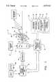
- FIG. 1is a block diagram which illustrates the multifunction antenna system in accordance with the present invention
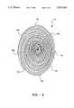
- FIG. 2is a schematic representation of a multiple arm spiral antenna which may be used in accordance with the present invention
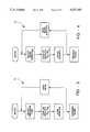
- FIG. 3is a flow diagram which illustrates the processing of an omni beam algorithm in accordance with the present invention
- FIG. 4is a flow diagram which illustrates the processing of a single beam pointing algorithm in accordance with the present invention
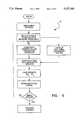
- FIG. 5is a flow diagram which illustrates the processing of a single null forming algorithm in accordance with the present invention
- FIG. 6is a flow diagram which illustrates the processing of a multiple beam and null forming algorithm in accordance with the present invention.
- FIG. 7is a flow diagram which illustrates the processing of an angle of arrival algorithm in accordance with the present invention.
- the antenna system 10includes a multiple arm spiral antenna 12 for transmitting and receiving radiating signals 46.
- the multiple arm spiral antenna 12is a single aperture beam former which has an array of N cylindrically symmetric spiral arm elements 14A through 14N.
- a multiple arm spiral antenna 12is shown in FIG. 2 which has eight conductive cylindrically symmetric spiral arm elements 14A through 14H.
- the conductive spiral arm elements 14A through 14Nmay be fabricated by photolithographic techniques known in the art. While the antenna 12 in FIG. 2 shows eight spiral arm elements 14A through 14H, any number of spiral arm elements may be employed for purposes of this invention.
- each of the N spiral elements 14A through 14Nare energized with one of N analytic voltage signals 20.
- the multiple arm spiral antenna 12may operate to transmit a radiating signal in response to the N analytic voltage signals 20 applied to the N spiral arm elements 14A through 14N.
- the multiple arm spiral antenna 12may operate to receive a radiating signal and produce in response thereto, N analytic voltage signals 20 on the N spiral elements 14A through 14N.
- the multiple arm spiral antenna 12is coupled to a vector weighter 16 via an antenna port 15 so that the N analytic voltage signals 20 communicate therebetween.
- the vector weighter 16is an analog hardware device made up of a plurality of PIN switches and RF circuitry.
- the vector weighter 16has phase shifting and attenuation capabilities which provide for analog signal weighting.
- the vector weighter 16is loaded with a combination of N vector weight coefficients W o through W n .
- the N vector weight coefficients W 0 through W nare essentially spherical harmonic coefficients which represent a predetermined beam pattern.
- the vector weighter 16provides analog signal weighting or multiplies N analog input signals input thereto by the N vector weight coefficients W o through W n to produce N weighted signals which form transmit and receive beams.
- Different sets of vector weight coefficients W o through W nmay be employed to produce a plurality of beams which are constructed from different spherical harmonic functions.
- the vector weighter 16has an output coupled to a receiver 24.
- the receiver 24receives the N weighted analog signals and provides a digital signal as an output.
- the digital signal produced by the receiver 24contains signal information received from the selected beam pattern. Such signal information may include communication, navigation, or identification signals or remote source direction information.
- the receiver 24has an output coupled to a central digital processing unit 26.
- the central digital processing unit 26may communicate with an input device 27 and an output device 28.
- the input and output devices 27 and 28allow for an operator and/or external hardware to interface therewith.
- the central digital processing unit 26processes the digital signals received from the receiver 24. In doing so, the central digital processing unit 26 may determine the direction of a given signal or may obtain information from a selected direction and determine whether or not the signal received is desirable or not.
- the antenna system 10may adapt to focus in on or provide increased gain in that direction.
- undesirable signalssuch as a jamming signal
- the antenna system 10may produce a null in the direction of the undesirable signal.
- a beam and null forming digital processor 30is provided for processing system data and selecting the proper combination of N vector weight coefficients W o through W n .
- the digital processor 30communicates with the central digital processing unit 26 to receive processed information therefrom. As a result, the digital processor 30 may determine which combination of vector weight coefficients W o through W n are to be selected by processing any operator inputs and prior data received by the antenna system 10.
- the digital processor 30further communicates with a global memory 32 or other external memory supply.
- the global memory 32is programmed with a plurality of beam forming and angle of arrival algorithms.
- the beam forming algorithmsmay include an omni beam algorithm 34 for providing preset omni beam patterns.
- a single steered beam forming algorithm 36may be employed for steering an antenna beam in a desired direction.
- a single null forming algorithm 38may be employed for adaptively providing a null or a decreased gain in a particular direction.
- a multiple beam and null forming algorithm 40may be employed for producing a beam having multiple combinations of increased gains and nulls.
- an angle of arrival algorithm 42may be employed for processing information received from a desired direction.
- Each of the beam forming and angle of arrival algorithmsare represented by a plurality of predetermined combinations of N vector weight coefficients W o through W n .
- These combinations of vector weight coefficients W o through W nare preferably generated as a result of prior testing and as such provide predetermined vector information for the particular multiple arm spiral antenna 12 employed.
- the global memory 32may further include additional predetermined data such as known positions of any desirable or undesirable signal sources. Such information may enable the digital processor 30 to select vector weight coefficients W o through W n which conform with such information.
- the beam and null forming digital processor 30selects the proper set of vector weight coefficients W o through W n from the global memory 32 and loads the selected set of vector weight coefficients W o through W n as an output into the vector weighter 16.
- the vector weighter 16then multiplies the vector weight coefficients W o through W n by vector weighter input signals to produce N weighted signals which have spherical harmonic coefficients.
- vector weighter input signalsmay include a transmit input signal 18 such as a communication signal.
- the vector weighter input signalsinclude the N analytic voltage signals 20.
- the selected vector weight coefficients W o through W nessentially decompose the vector weighter input signals into cylindrically symmetric modes representative of predetermined beam patterns.
- Specific antenna characteristics for the multiple arm spiral antenna 12are thereby contained in the spherical harmonic coefficients.
- an N arm spiral antenna 12 patternmay be characterized by N 2 spherical harmonic functions.
- the beam patterncan be shaped in any of a plurality of predetermined beam patterns.
- the multifunction antenna system 10may further provide for real time processing of the beam forming and angle of arrival algorithms.
- a high speed real time processormay be employed as the beam and null forming digital processor 30.
- the high speed digital processor 30may thereby process the selected algorithm to generate the proper vector weight coefficients W o through W n as needed.
- the multifunction antenna system 10operates to transmit a radiating signal in accordance with a selected beam pattern.
- the beam and null forming processor 30communicates with the global memory 32 to select or generate a set of predetermined vector weight coefficients W o through W n provided by the plurality of beam-forming algorithms.
- the digital processor 30then loads the vector weight coefficients W o through W n into the vector weighter 16.
- the vector weighter 16further receives a transmit input signal 18 which may include any desired transmission data. As such, the vector weighter 16 multiplies the vector weight coefficients W o through W n by the transmit input signal 18 to form N analytic voltage signals 20.
- the N analytic voltage signals 20are transmitted to the associated N cylindrical arm elements 14A through 14N of the multiple arm spiral antenna 12 via antenna port 15.
- the multiple arm spiral antenna 12then transmits a radiating signal in a selected beam pattern in response to the N analytic voltage signals via the spiral arm elements 14A through 14N.
- the multifunction antenna system 10In the receive mode, the multifunction antenna system 10 generally operates to receive radiating signals over a wide field of view and to process information from a desired direction or beam pattern. In doing so, the multiple arm spiral antenna 12 receives a radiating signal 46 from a radiating source 44 or any number of sources. As such, each of the spiral arm elements 14A through 14N of the multiple arm spiral antenna 12 are energized with an analytic voltage signal in response to the received radiating signal 46. The energized spiral arm elements 14A through 14N together provide for the N analytic voltage signals 20 which are transmitted to the vector weighter 16. The output of the vector weighter 16 is received by the receiver 24 and thereafter supplied to the central digital processing unit 26. The central digital processing unit 26 processes the digital data and provides control information as an output to the beam and null forming digital processor 30.
- the digital processor 30processes the control information and determines which set of vector weight coefficients W o through W n should be selected. This determination may depend on any operator control signal or prior received data. For instance, an operator may select the beam pattern. In addition, the selected beam pattern may be effected by prior received data and may adapt to changing conditions.
- the digital processor 30selects or generates the set of N vector weight coefficients W o through W n and loads the selected set of vector weight coefficients W o through W n into the vector weighter 16.
- the vector weighter 16thereby multiplies the selected set of vector weight coefficients W o through W n by the N analytic arm signals 20 so as to produce N weighted output signals 22.
- the N weighted output signals 22contain the data received from the selected beam pattern in accordance with the selected vector weight coefficients W o through W n .
- radiating signals which are received from non-selected directions not within the beam patternare not processed and are thereby spatially filtered.
- the antenna system 10may further employ an angle of arrival algorithm 42 which may determine the direction of an emitting source such as radiating source 44.
- This featureis based on unique properties for phase and amplitude of the multiple arm spiral antenna 12.
- the phase of the N analytic signals 20are generally linearly related to the azimuth position of the source.
- the amplitude of the N analytic signals 20are generally related to the elevation position of the source.
- the vector weighter 16is set to sequentially (in time) provide the vector weight coefficients W o through W n for certain signals received.
- the phase of these modesare used to determine the azimuth angle ⁇ of the source while the square of amplitudes are used to determine the elevation angle ⁇ of the source with respect to the antenna coordinates.
- the azimuth and elevation angles ⁇ and ⁇provide the vector direction of the source which is passed to the central processing unit 26. If only the azimuth direction of the source is needed, the elevation angle calculation is generally not performed.
- FIG. 3illustrates an omni beam algorithm 34 which may be employed in conjunction with the present invention.
- the omni beam algorithm 34operates such that the desired type of omni beam is first selected.
- the proper set of vector weights W o through W nare then selected and loaded into the digital processor 30 which loads the vector weight coefficients into the vector weighter 16.
- the antenna system 10then proceeds to transmit or receive signals in accordance with the omni beam algorithm 34.
- FIG. 4illustrates the flow diagram for a single beam pointing algorithm 36.
- the single beam pointing algorithm 36is likewise selected by choosing the appropriate set of vector weight coefficients W o through W n
- the antenna system 10then processes a transmit or receive signal to provide increased gain in the desired beam direction.
- FIG. 5illustrates a null forming algorithm 38.
- the null forming algorithm 38essentially produces a decreased amplitude in a particular direction with the maximum null bandwidth. That is, the null depth is generally maintained over the widest possible frequency range.
- FIG. 6illustrates the flow diagram for a multiple beam and null forming algorithm 40. As such, the multiple beam and null forming algorithm 40 provides a plurality of beams with increased gains and nulls in particular directions to provide a desired beam pattern.
- a complex multifunction antenna systemmay be provided for transmitting beams in a steered direction or a plurality of directions while decreasing the gain in other directions.
- An angle of arrival algorithmis shown in FIG. 7.
- the angle of arrival algorithm 42operates to detect the direction of signals received.
- analog vector weighter 16may be implemented with digital processing techniques.
- digital processing unit 26 and digital processor 30may be implemented with analog circuitry.
Landscapes
- Engineering & Computer Science (AREA)
- Radar, Positioning & Navigation (AREA)
- Remote Sensing (AREA)
- Physics & Mathematics (AREA)
- General Physics & Mathematics (AREA)
- Computer Networks & Wireless Communication (AREA)
- Variable-Direction Aerials And Aerial Arrays (AREA)
Abstract
Description
Claims (16)
Priority Applications (1)
| Application Number | Priority Date | Filing Date | Title |
|---|---|---|---|
| US07/902,334US5327143A (en) | 1992-06-22 | 1992-06-22 | Multiple arm spiral antenna system with multiple beamforming capability |
Applications Claiming Priority (1)
| Application Number | Priority Date | Filing Date | Title |
|---|---|---|---|
| US07/902,334US5327143A (en) | 1992-06-22 | 1992-06-22 | Multiple arm spiral antenna system with multiple beamforming capability |
Publications (1)
| Publication Number | Publication Date |
|---|---|
| US5327143Atrue US5327143A (en) | 1994-07-05 |
Family
ID=25415706
Family Applications (1)
| Application Number | Title | Priority Date | Filing Date |
|---|---|---|---|
| US07/902,334Expired - LifetimeUS5327143A (en) | 1992-06-22 | 1992-06-22 | Multiple arm spiral antenna system with multiple beamforming capability |
Country Status (1)
| Country | Link |
|---|---|
| US (1) | US5327143A (en) |
Cited By (20)
| Publication number | Priority date | Publication date | Assignee | Title |
|---|---|---|---|---|
| GB2307348A (en)* | 1995-11-13 | 1997-05-21 | Nec Corp | Communication apparatus with directional antenna system |
| FR2766994A1 (en)* | 1997-08-04 | 1999-02-05 | Samsung Electronics Co Ltd | ADAPTIVE PHASE NETWORK ANTENNA USING A WEIGHT MEMORY BLOCK |
| US6192256B1 (en)* | 1996-05-17 | 2001-02-20 | Motorola, Inc | Devices for transmitter path weights and methods therefor |
| US6333713B1 (en) | 1999-08-24 | 2001-12-25 | Matsushita Electric Industrial Co., Ltd. | Direction estimating apparatus, directivity controlling antenna apparatus, and direction estimating method |
| US6535610B1 (en) | 1996-02-07 | 2003-03-18 | Morgan Stanley & Co. Incorporated | Directional microphone utilizing spaced apart omni-directional microphones |
| US6593880B2 (en)* | 1996-10-10 | 2003-07-15 | Teratech Corporation | Communication system using geographic position data |
| EP1107475A3 (en)* | 1999-12-09 | 2003-08-13 | Texas Instruments Incorporated | Beam forming for transmit using bluetooth modified hopping sequences (BFTBMH) |
| US20040224637A1 (en)* | 2002-11-04 | 2004-11-11 | Silva Marcus Da | Directed wireless communication |
| US6894643B2 (en) | 2000-08-01 | 2005-05-17 | Fujitsu Limited | Apparatus for and methods of receiving a transmission signal |
| US20060033659A1 (en)* | 2004-08-10 | 2006-02-16 | Ems Technologies Canada, Ltd. | Mobile satcom antenna discrimination enhancement |
| US7088288B1 (en)* | 2003-01-10 | 2006-08-08 | Xilinx, Inc. | Method and circuit for controlling an antenna system |
| US20080303714A1 (en)* | 2007-05-29 | 2008-12-11 | Ezal Kenan O | Compact single-aperture antenna and navigation system |
| US20100007555A1 (en)* | 2007-05-29 | 2010-01-14 | Toyon Research Corporation | Compact single-aperture antenna and direction-finding navigation system |
| CN103885045A (en)* | 2014-04-09 | 2014-06-25 | 西安电子科技大学 | Sub-array division based circulation combined adaptive beam forming method |
| WO2017003456A1 (en)* | 2015-06-30 | 2017-01-05 | Sterling Christopher | Antenna apparatus and software for emulating same |
| US9582470B2 (en) | 2014-01-10 | 2017-02-28 | Christopher Sterling | Antenna apparatus and software for emulating same |
| US10075221B2 (en)* | 2015-12-31 | 2018-09-11 | Motorola Mobility Llc | Method and apparatus for directing an antenna beam based on motion of a communication device |
| US20180375559A1 (en)* | 2013-11-20 | 2018-12-27 | Samsung Electronics Co., Ltd. | Method and apparatus for beamforming in wireless communication system |
| US10177451B1 (en)* | 2014-08-26 | 2019-01-08 | Ball Aerospace & Technologies Corp. | Wideband adaptive beamforming methods and systems |
| US10433184B2 (en) | 2015-12-31 | 2019-10-01 | Motorola Mobility Llc | Method and apparatus for directing an antenna beam based on a location of a communication device |
Citations (4)
| Publication number | Priority date | Publication date | Assignee | Title |
|---|---|---|---|---|
| US3903522A (en)* | 1971-02-08 | 1975-09-02 | Texas Instruments Inc | Direction-finding system having slope control means |
| US4160975A (en)* | 1978-06-27 | 1979-07-10 | Raytheon Company | Correction circuit for wide bandwidth antenna |
| US4885590A (en)* | 1989-04-14 | 1989-12-05 | General Electric Company | Blind speed elimination for dual displaced phase center antenna radar processor mounted on a moving platform |
| US5172125A (en)* | 1980-12-29 | 1992-12-15 | Raytheon Company | All weather tactical strike system (AWISS) and method of operation |
- 1992
- 1992-06-22USUS07/902,334patent/US5327143A/ennot_activeExpired - Lifetime
Patent Citations (4)
| Publication number | Priority date | Publication date | Assignee | Title |
|---|---|---|---|---|
| US3903522A (en)* | 1971-02-08 | 1975-09-02 | Texas Instruments Inc | Direction-finding system having slope control means |
| US4160975A (en)* | 1978-06-27 | 1979-07-10 | Raytheon Company | Correction circuit for wide bandwidth antenna |
| US5172125A (en)* | 1980-12-29 | 1992-12-15 | Raytheon Company | All weather tactical strike system (AWISS) and method of operation |
| US4885590A (en)* | 1989-04-14 | 1989-12-05 | General Electric Company | Blind speed elimination for dual displaced phase center antenna radar processor mounted on a moving platform |
Cited By (38)
| Publication number | Priority date | Publication date | Assignee | Title |
|---|---|---|---|---|
| US5719583A (en)* | 1995-11-13 | 1998-02-17 | Nec Corporation | Mobile communication system which performs antenna gain control |
| GB2307348B (en)* | 1995-11-13 | 1999-11-10 | Nec Corp | Mobile communication system |
| GB2307348A (en)* | 1995-11-13 | 1997-05-21 | Nec Corp | Communication apparatus with directional antenna system |
| US6535610B1 (en) | 1996-02-07 | 2003-03-18 | Morgan Stanley & Co. Incorporated | Directional microphone utilizing spaced apart omni-directional microphones |
| US6192256B1 (en)* | 1996-05-17 | 2001-02-20 | Motorola, Inc | Devices for transmitter path weights and methods therefor |
| US20040104839A1 (en)* | 1996-10-10 | 2004-06-03 | Teratech Corporation | Communication system using geographic position data |
| US6593880B2 (en)* | 1996-10-10 | 2003-07-15 | Teratech Corporation | Communication system using geographic position data |
| FR2766994A1 (en)* | 1997-08-04 | 1999-02-05 | Samsung Electronics Co Ltd | ADAPTIVE PHASE NETWORK ANTENNA USING A WEIGHT MEMORY BLOCK |
| GB2328320A (en)* | 1997-08-04 | 1999-02-17 | Samsung Electronics Co Ltd | Adaptive phased array antenna with weight memory |
| GB2328320B (en)* | 1997-08-04 | 2000-03-15 | Samsung Electronics Co Ltd | Adaptive phased array antenna using weighting memory unit |
| US6049307A (en)* | 1997-08-04 | 2000-04-11 | Samsung Electronics Co., Ltd. | Adaptive phased array antenna using weight memory unit |
| US6333713B1 (en) | 1999-08-24 | 2001-12-25 | Matsushita Electric Industrial Co., Ltd. | Direction estimating apparatus, directivity controlling antenna apparatus, and direction estimating method |
| US7164704B1 (en)* | 1999-12-09 | 2007-01-16 | Texas Instruments Incorporated | Beam forming for transmit using bluetooth modified hopping sequences (BFTBMH) |
| US20060280143A1 (en)* | 1999-12-09 | 2006-12-14 | Dabak Anand G | Beam Forming for Transmit Using Bluetooth Modified Hopping Sequences (BFTBMH) |
| US7634019B2 (en) | 1999-12-09 | 2009-12-15 | Texas Instruments Incorporated | Beam forming for transmit using bluetooth modified hopping sequences (BFTBMH) |
| EP1107475A3 (en)* | 1999-12-09 | 2003-08-13 | Texas Instruments Incorporated | Beam forming for transmit using bluetooth modified hopping sequences (BFTBMH) |
| US6894643B2 (en) | 2000-08-01 | 2005-05-17 | Fujitsu Limited | Apparatus for and methods of receiving a transmission signal |
| US11777569B2 (en) | 2002-11-04 | 2023-10-03 | Xr Communications Llc | Directed wireless communication |
| US8412106B2 (en)* | 2002-11-04 | 2013-04-02 | Xr Communications, Llc | Directed wireless communication |
| US10009085B2 (en) | 2002-11-04 | 2018-06-26 | Xr Communications, Llc | Directed wireless communication |
| US10715235B2 (en) | 2002-11-04 | 2020-07-14 | Xr Communications, Llc | Directed wireless communication |
| US10594376B2 (en) | 2002-11-04 | 2020-03-17 | Xr Communications, Llc | Directed wireless communication |
| US20040224637A1 (en)* | 2002-11-04 | 2004-11-11 | Silva Marcus Da | Directed wireless communication |
| US7088288B1 (en)* | 2003-01-10 | 2006-08-08 | Xilinx, Inc. | Method and circuit for controlling an antenna system |
| US20060033659A1 (en)* | 2004-08-10 | 2006-02-16 | Ems Technologies Canada, Ltd. | Mobile satcom antenna discrimination enhancement |
| US20080303714A1 (en)* | 2007-05-29 | 2008-12-11 | Ezal Kenan O | Compact single-aperture antenna and navigation system |
| US20100007555A1 (en)* | 2007-05-29 | 2010-01-14 | Toyon Research Corporation | Compact single-aperture antenna and direction-finding navigation system |
| US8305265B2 (en) | 2007-05-29 | 2012-11-06 | Toyon Research Corporation | Radio-based direction-finding navigation system using small antenna |
| US8704728B2 (en) | 2007-05-29 | 2014-04-22 | Toyon Research Corporation | Compact single-aperture antenna and direction-finding navigation system |
| US20180375559A1 (en)* | 2013-11-20 | 2018-12-27 | Samsung Electronics Co., Ltd. | Method and apparatus for beamforming in wireless communication system |
| US11264714B2 (en)* | 2013-11-20 | 2022-03-01 | Samsung Electronics Co., Ltd. | Method and apparatus for beamforming in wireless communication system |
| US9582470B2 (en) | 2014-01-10 | 2017-02-28 | Christopher Sterling | Antenna apparatus and software for emulating same |
| CN103885045B (en)* | 2014-04-09 | 2016-02-10 | 西安电子科技大学 | Based on the circulation associating Adaptive beamformer method of Subarray partition |
| CN103885045A (en)* | 2014-04-09 | 2014-06-25 | 西安电子科技大学 | Sub-array division based circulation combined adaptive beam forming method |
| US10177451B1 (en)* | 2014-08-26 | 2019-01-08 | Ball Aerospace & Technologies Corp. | Wideband adaptive beamforming methods and systems |
| WO2017003456A1 (en)* | 2015-06-30 | 2017-01-05 | Sterling Christopher | Antenna apparatus and software for emulating same |
| US10075221B2 (en)* | 2015-12-31 | 2018-09-11 | Motorola Mobility Llc | Method and apparatus for directing an antenna beam based on motion of a communication device |
| US10433184B2 (en) | 2015-12-31 | 2019-10-01 | Motorola Mobility Llc | Method and apparatus for directing an antenna beam based on a location of a communication device |
Similar Documents
| Publication | Publication Date | Title |
|---|---|---|
| US5327143A (en) | Multiple arm spiral antenna system with multiple beamforming capability | |
| US6205224B1 (en) | Circularly symmetric, zero redundancy, planar array having broad frequency range applications | |
| Monzingo et al. | Introduction to adaptive arrays | |
| US5008680A (en) | Programmable beam transform and beam steering control system for a phased array radar antenna | |
| US5894598A (en) | Radio communication system using portable mobile terminal | |
| US4489325A (en) | Electronically scanned space fed antenna system and method of operation thereof | |
| US5838284A (en) | Spiral-shaped array for broadband imaging | |
| US6636177B1 (en) | Volumetric phased array antenna system | |
| US11152986B2 (en) | Fast spatial search using phased array antennas | |
| US3987444A (en) | Interference rejection system for multi-beam antenna having single control loop | |
| US11329388B2 (en) | Antenna for transmitting and/or receiving an electromagnetic wave, and system comprising this antenna | |
| Zhou et al. | Joint design of transmit and receive beamforming for transmit subaperturing MIMO radar | |
| Taillefer et al. | Reactance-domain ESPRIT algorithm for a hexagonally shaped seven-element ESPAR antenna | |
| US6906665B1 (en) | Cluster beam-forming system and method | |
| US3737906A (en) | Electrically steerable aircraft mounted antenna | |
| US6759978B2 (en) | Cross-link antenna system | |
| Haupt | The development of smart antennas | |
| US20080068266A1 (en) | Beamforming for spatial sidelobe cancellation and AMR direction finding | |
| AU2020386840B2 (en) | Beam spoiling | |
| Dorsey et al. | Transmit and receive circular array pattern synthesis for radar applications | |
| JPH0682980B2 (en) | Monopulse antenna with improved sidelobe suppression | |
| KR102006191B1 (en) | Apparatus for directional antenna tracking in multiple air-vehicle communication system and the method thereof | |
| KR20230015743A (en) | Multi-input multi-output radar device including antenna sub-arrays and method of operating thereof | |
| JPS6376504A (en) | antenna device | |
| Rahaman et al. | Linearly-arranged Concentric Circular Antenna Array Using Robust VDL technique |
Legal Events
| Date | Code | Title | Description |
|---|---|---|---|
| AS | Assignment | Owner name:TRW INC., A CORP. OF OH, CALIFORNIA Free format text:ASSIGNMENT OF ASSIGNORS INTEREST.;ASSIGNORS:GOETZ, ALLAN C.;BOOLOS, TIMOTHY L.;REEL/FRAME:006168/0067 Effective date:19920605 | |
| STCF | Information on status: patent grant | Free format text:PATENTED CASE | |
| FEPP | Fee payment procedure | Free format text:PAYOR NUMBER ASSIGNED (ORIGINAL EVENT CODE: ASPN); ENTITY STATUS OF PATENT OWNER: LARGE ENTITY | |
| FPAY | Fee payment | Year of fee payment:4 | |
| FPAY | Fee payment | Year of fee payment:8 | |
| AS | Assignment | Owner name:NORTHROP GRUMMAN CORPORATION, CALIFORNIA Free format text:ASSIGNMENT OF ASSIGNORS INTEREST;ASSIGNOR:TRW, INC. N/K/A NORTHROP GRUMMAN SPACE AND MISSION SYSTEMS CORPORATION, AN OHIO CORPORATION;REEL/FRAME:013751/0849 Effective date:20030122 Owner name:NORTHROP GRUMMAN CORPORATION,CALIFORNIA Free format text:ASSIGNMENT OF ASSIGNORS INTEREST;ASSIGNOR:TRW, INC. N/K/A NORTHROP GRUMMAN SPACE AND MISSION SYSTEMS CORPORATION, AN OHIO CORPORATION;REEL/FRAME:013751/0849 Effective date:20030122 | |
| FPAY | Fee payment | Year of fee payment:12 | |
| AS | Assignment | Owner name:NORTHROP GRUMMAN SPACE & MISSION SYSTEMS CORP.,CAL Free format text:ASSIGNMENT OF ASSIGNORS INTEREST;ASSIGNOR:NORTHROP GRUMMAN CORPORTION;REEL/FRAME:023699/0551 Effective date:20091125 Owner name:NORTHROP GRUMMAN SPACE & MISSION SYSTEMS CORP., CA Free format text:ASSIGNMENT OF ASSIGNORS INTEREST;ASSIGNOR:NORTHROP GRUMMAN CORPORTION;REEL/FRAME:023699/0551 Effective date:20091125 | |
| AS | Assignment | Owner name:NORTHROP GRUMMAN SYSTEMS CORPORATION,CALIFORNIA Free format text:ASSIGNMENT OF ASSIGNORS INTEREST;ASSIGNOR:NORTHROP GRUMMAN SPACE & MISSION SYSTEMS CORP.;REEL/FRAME:023915/0446 Effective date:20091210 Owner name:NORTHROP GRUMMAN SYSTEMS CORPORATION, CALIFORNIA Free format text:ASSIGNMENT OF ASSIGNORS INTEREST;ASSIGNOR:NORTHROP GRUMMAN SPACE & MISSION SYSTEMS CORP.;REEL/FRAME:023915/0446 Effective date:20091210 |