US5326931A - Cable distribution interface unit - Google Patents
Cable distribution interface unitDownload PDFInfo
- Publication number
- US5326931A US5326931AUS07/795,589US79558991AUS5326931AUS 5326931 AUS5326931 AUS 5326931AUS 79558991 AUS79558991 AUS 79558991AUS 5326931 AUS5326931 AUS 5326931A
- Authority
- US
- United States
- Prior art keywords
- housing
- cable
- module
- slots
- cables
- Prior art date
- Legal status (The legal status is an assumption and is not a legal conclusion. Google has not performed a legal analysis and makes no representation as to the accuracy of the status listed.)
- Expired - Fee Related
Links
- 238000006073displacement reactionMethods0.000claimsdescription2
- 238000000605extractionMethods0.000claims1
- 238000004519manufacturing processMethods0.000claims1
- 239000000463materialSubstances0.000abstractdescription7
- 238000000034methodMethods0.000abstractdescription5
- 238000009434installationMethods0.000description10
- 238000010276constructionMethods0.000description2
- 238000003780insertionMethods0.000description2
- 230000037431insertionEffects0.000description2
- 238000007792additionMethods0.000description1
- 238000005452bendingMethods0.000description1
- 238000004891communicationMethods0.000description1
- 230000000694effectsEffects0.000description1
- 229910052602gypsumInorganic materials0.000description1
- 239000010440gypsumSubstances0.000description1
- 239000011796hollow space materialSubstances0.000description1
- 238000009413insulationMethods0.000description1
- 230000013011matingEffects0.000description1
- 239000011159matrix materialSubstances0.000description1
- 239000011120plywoodSubstances0.000description1
- 125000006850spacer groupChemical group0.000description1
- 238000009966trimmingMethods0.000description1
- 238000011144upstream manufacturingMethods0.000description1
Images


Classifications
- H—ELECTRICITY
- H02—GENERATION; CONVERSION OR DISTRIBUTION OF ELECTRIC POWER
- H02G—INSTALLATION OF ELECTRIC CABLES OR LINES, OR OF COMBINED OPTICAL AND ELECTRIC CABLES OR LINES
- H02G3/00—Installations of electric cables or lines or protective tubing therefor in or on buildings, equivalent structures or vehicles
- H02G3/02—Details
- H02G3/08—Distribution boxes; Connection or junction boxes
- H02G3/12—Distribution boxes; Connection or junction boxes for flush mounting
- H02G3/123—Distribution boxes; Connection or junction boxes for flush mounting in thin walls
- H—ELECTRICITY
- H02—GENERATION; CONVERSION OR DISTRIBUTION OF ELECTRIC POWER
- H02G—INSTALLATION OF ELECTRIC CABLES OR LINES, OR OF COMBINED OPTICAL AND ELECTRIC CABLES OR LINES
- H02G3/00—Installations of electric cables or lines or protective tubing therefor in or on buildings, equivalent structures or vehicles
- H02G3/02—Details
- H02G3/08—Distribution boxes; Connection or junction boxes
- H02G3/18—Distribution boxes; Connection or junction boxes providing line outlets
Definitions
- This inventionrelates to an electrical interface distribution unit and method for interconnecting signal cables within a wall of a building structure or the like.
- the cablesmay be wall mounted or surface mounted, but in general, such mountings are aesthetically unacceptable, and in certain instances, practically undesirable by virtue of damage to such cables by the normal traffic of the buildings, including the movement of furniture, equipment, and the like.
- Most wall constructionsinclude the use of studs which are nominally of 2" ⁇ 4" dimensions over which is applied drywall or paneling to result in a hollow space or volume between the sheet material defining the walls. As can be appreciated, this volume is limited in depth.
- Patent Application Ser. No. 07,618,766, filed Nov. 27, 1990, and directed to a convenience electrical outlet assemblyrepresents one solution wherein power and signal outlets are combined and employed using a hybrid ribbon cable for an intelligent wiring system for a building.
- a multi-function ribbon cableis attached to a housing which has receptacles into which terminals attached to modules are plugged to effect a termination.
- a special moduleis used to accommodate data or communication cables inserted into the housing, which is fitted within a hole in the sheet material of a wall.
- the numbers of coaxial and telephone cablesare relatively limited inputs to a receptacle associated with such device.
- U.S. Pat. No. 4,756,695 granted Jul. 12, 1988 and drawn to a local area network interfaceaccomplishes a similar function with respect to telephone cables.
- a wall boxis made to accommodate connectors terminated to cable and plugged therein to join modules accommodated by the wall box.
- the present inventionhas as an object the provision of a cable distribution unit and method of installation wherein relatively large numbers of cables can be accommodated in a relatively small volume within the sheet material defining a wall structure of a building.
- the inventionhas as a further object the provision of a housing and mounting arrangement which is easy to use and reduces the amount of labor for the interconnection of cables providing distribution in a building structure.
- Still a further objectis to provide a low cost solution to the termination and distribution of cable which can readily fit within the wall of a building structure.
- the present inventionachieves the foregoing objects through the use of a particular housing having apertures or slots therein which extend through portions of the side walls of the housing and through the back of the housing with such slots being of a dimension to readily allow the pulling of cable through the housing and the pushing of cable back through the housing to be accommodated within the volume of the wall.
- the width of the slotsare of such a dimension as to allow the cable alone to be inserted therethrough into the housing.
- the connectorafter the connector is installed at the end of the coax cable, it will not slip out but is trapped, as the width of the connector is greater than said slot dimension.
- the housingfurther includes mounting means in the form of slots allowing the sliding engagement and mounting of electronic modules such as those used for cable signal splitting and signal combination as well as those used for telephone distribution, all within the volume of the housing.
- the inventioncontemplates a relatively large number of cables terminated for distribution and held within the housing. Cable signal splitters or combiners are arranged so that input and output connections have a common orientation so that the cables will not have to extend into a module from one side and out of the module from the other thus occupying substantial interior volume.
- the inventioncontemplates the use of modules which may be fitted back to back and, following termination, readily slid within slots interiorly of the housing with a telephone cable connector mounted on top of the modules but still within the volume of the housing.
- the nature and arrangement of the housing of the inventionallows cable to be pulled through a hole in a sheet of material defining a wall terminated first to terminals such as coaxial connectors terminated to the electronic modules and then the housing slid into a hole in the wall with the modules then inserted in such housing, the cables sliding back through the slots into the interior of the wall.
- This device and the method related theretoallows for a simple installation of distribution devices, a minimum use of cable length, and still ready access and removal of electronic modules and terminals for changes, repair and additional circuits.
- FIG. 1is a perspective view, showing the housing of the invention, fully loaded, as installed in a wall with a cover plate expanded therefrom.
- FIG. 2is a view of the structure of FIG. 1, less the cover plate but with the telephone connector as terminated removed from the housing of the invention.
- FIG. 3is a view of the structure of FIG. 2 with the telephone connection removed and the electronic module in the form of a cable splitter removed, with wires attached.
- FIG. 4is a perspective view of the invention housing, electronic module and telephone module unterminated and removed from the housing.
- FIG. 5is a view, in perspective, of the housing of the invention having unterminated cables pulled therethrough with the housing removed from a wall structure.
- FIG. 6is a view of cables pulled through a hole in the sheet defining a wall structure.
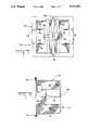
- FIG. 7is a plan view of the housing of the invention.
- FIG. 8is a side elevational and partial, sectional view of the housing shown in FIG. 7.
- FIG. 1shows an assembly 10 which includes a face plate 12 aligned for installation relative to a cable Distribution Interface Unit (DIU) 11 mounted in a wall.
- the wall constructioncan best be seen in FIG. 3 to include sheets of material 16 and 18 which are typically gypsum board or drywall; or plywood, in the case of an exterior wall with respect to 16, and paneling with respect sheet 18. These sheets are anchored to studs 20, one of which is shown, to form a wall structure and define an interior volume between the sheets 16 and 18 and the studs 20.
- cables to include power, telephone, television, and/or data cablesare laid within the space between sheets 16 and 18 prior to one or the other of the sheets being fastened to a stud 20.
- the cablesmay be brought down from a space above a given room or, up from a space beneath a given room, or through studs by virtue of apertures such as 22 made in stud 20 and revealed in FIG. 3.
- studsare typically 31/2 inches in depth and placed on 16-inch centers.
- FIG. 6shows coaxial cables 62 and telephone cables 64 pulled through a hole in sheet 18 and through a bracket 19 typically anchored to a stud 20 by a flange 21 and fasteners applied therethrough.
- the bracket 19includes an inner opening which is used as a guide for forming the hole in sheet 18 after application of the sheet over the bracket.
- the bracketsee FIG. 3, includes a series of fastener apertures 23 distributed around the periphery directed to receive fasteners applied through a DIU housing 24.
- Housing 24includes a flange 26 which extends therearound in the manner shown in FIGS. 1, 3, 7, and 8.
- This flangeincludes fastener apertures 28 which are aligned with the apertures 23 in bracket 19 and through which fasteners such as screws may be applied to lock the housing 24 to the bracket 19. It is important that the flange 26, when attached to the bracket 19, traps the wall 18 between them when the fasteners are attached through apertures 23,28. This allows wall 18 to be of any thickness and it still gets attached without special spacers. It also results in a very strong structure when assembled. At the top and bottom of flange 26 are further fastener apertures 30 which receive fasteners 14 extended through face plate 12 to lock the face plate to the housing and cover over the interior of the housing.
- the housing 24includes, extending rearwardly of the flange 26, a bottom wall 32, a top wall 34, and a back wall 36.
- projections of the housing materialwhich include box-like structures 38 which carry, at the inner face, slots 40 beveled as at 42 and positioned to receive electronic modules in the manner to be described.
- the projections 38include, as is shown in FIG. 8, elongated latches 46 having latch surfaces 48 at the ends thereof. As can be seen in FIG. 7, the latches 46 extend outwardly relative to the interior of housing 24 and are positioned on both sides of the housing in the manner shown in FIG. 7. As can be seen in FIGS.
- the surfaces 32, 34, and 36 of housing 24include slots 50 which extend across the bottom and top and partially across the back wall 36.
- These slotshave, by virtue of the disposition in the wall surfaces of the housing, a particular advantage, and the slots are made of a width to readily accommodate movement of the cable through the slots and through the interior of the housing facilitating a ready sliding of the cable relative to the housing and relative to being pulled through the housing or pushed back through the housing.
- the width of the slotsare of such a dimension as to allow the cable alone to be inserted therethrough into the housing.
- the portions of slots 50 in wall 36facilitate sliding the housing 24 relative to the cables, to fit the housing onto the wall.
- the various types of cablesare pulled through the wall opening in sheet 18 and thereafter pulled through the slots 50 in the housing 24 in the manner shown in FIG. 5.
- the various cablesincluding the coaxial cables 60 and 62, as well as the telephone cable 64, are cut to an appropriate length which will facilitate termination of the cables and a pushing of the housing 24 back into the hole and mounting in bracket 19 with the cables later being pushed into the cavity within the wall.
- the coaxial cablesare terminated by coaxial connector fittings, and the telephone cables are taped together and set aside. Following termination of the coaxial cables with coaxial connectors, such cables are connected to an electronic module 70, as shown in FIGS. 3 and 4.
- the module 70includes a pair of coaxial signal splitters 72 and 74 which carry coaxial connector receptacles 76 to receive coaxial connector plugs 77 which are terminated to the end of the cables.
- the connectorsare typical of coaxial connectors, and are widely used for coaxial cable termination.
- the splitter devices 74 and 76are of a configuration having a flat flange 78 with each of the splitter devices with such flanges being placed back to back and with the coaxial connectors 76 oppositely oriented.
- each splitter devicethere are five connectors for each splitter device which, in the preferred embodiment, include one "head end” connector and up to four connectors supplied by a signal fed through the "head end” connector and split into as many as four output channels.
- the "head end" connector for one of the splitter deviceswould be from a source such as a cable, a satellite receiver or some other television receiver split into the desired number of channels and fed out through the comparable number of cables to receivers such as television receivers located in four different building units, house rooms, or apartments of a building structure or the like.
- the other splitter device 74may be similarly used with a single input through one of the coaxial connectors which could come, for example, from an interior source to the building such as a video camera or security sensing device to be channeled to four receivers also located within the building. It is to be understood that while the present example is related to coaxial splitter devices, the invention contemplates the opposite wherein signals from the four different input devices are combined into a single output device through an output coaxial connector.
- Splitter and combined devicesare well known and available commercially. To be noted, however, is the arrangement of the electronic module package wherein input and output connectors are arranged in sets with the various connectors for a given set being on the same side of the splitter device.
- the splitter devicesincluding particularly the flange elements 78 are fitted interiorly of housing 24 by being fitted inwardly thereof with the flanges 78 slid into the slots 40, the bevel portions 42 guiding such insertion.
- the cables terminated to the splitter deviceswill be pushed to slide through the slots 50 back into the cavity of the wall with relative ease due to the design and dimensioning of the slots 50.
- the upper cables 60will pass through the housing 24 and upwardly into the wall with the cables labeled 62 passing downwardly into the cavity beneath the mounting location of housing 24.
- the telephone cablesmay be selectively terminated in telephone distribution block 80, shown in FIGS. 1, 2, and 4.
- the block 80includes a plastic housing having side walls 82, cable strain relief slots 84, and a series of individually mounted electrical terminals 86 arrayed in a matrix extending from the floor of the device 80.
- the terminals 86may be insulation displacement connection (IDC) type terminals into which insulated telephone wire can be driven to strip such wire and terminate the conductive core of such wire within a slot.
- IDCinsulation displacement connection
- the telephone wiresmay represent inputs from a telephone cable carrying signals to and from the DIU and as well, wires which go out to the individual telephone units in a building.
- the telephone blockmay be placed within housing 24 by being inserted onto the top of projections 38 with the latch elements 46 receiving the outside walls of the block and with the latches 48 engaging the top edge surfaces of the walls 82 of the block. This is shown , as installed, in FIG. 1 and just prior to installation in FIG. 2. At this time, excess telephone wire will be driven to move through slots 50 into the interior of the wall as with respect to the coaxial cables.
- the first stepis to pull all cables to be terminated by the DIU through the hole in the interior wall sheet 18. Thereafter, the cables are trimmed to an appropriate length and fed through the housing 24 out of the wall through the slots 50 thereof. The housing 24 is then inserted and fastened to bracket 19 with the slots 50 in the rear wall of the housing facilitating such insertion and manipulation. Thereafter, the coaxial cables are terminated to coaxial connectors which are then attached into the coaxial splitters. The splitter is then slid into position within the housing as described with the coaxial cables further backing into the space in the wall principally above and below the housing 24.
- the telephone cablesmay be terminated to the telephone block with the telephone block fitted in the housing as described and finally, after a checkout of circuits, the face plate, including fasteners 14 applied to seal up the interior of the DIU as shown in FIG. 1.
- the reverse procedurescan be used. The installation of coaxial cables first, followed by the more readily bendable telephone cables is preferred.
- While the inventionhas been related to particular types of electronic modules and telephone connectors, it is contemplated that other electronic modules, including particularly for those for data distribution may be employed. It is also contemplated that cables may be placed in a wall with the later installation of circuits following an initial installation which may utilize only one splitter device, another one being added at a later time with the cables both pulled through the slots 50 and pushed back through, with the housing in the wall. In most instances, however, the invention contemplates fitting the cables through the housing with the housing out of the wall and placing the housing back into the wall after it is loaded with splitter devices and a telephone block.
Landscapes
- Engineering & Computer Science (AREA)
- Architecture (AREA)
- Civil Engineering (AREA)
- Structural Engineering (AREA)
- Details Of Indoor Wiring (AREA)
Abstract
Description
Claims (11)
Priority Applications (1)
| Application Number | Priority Date | Filing Date | Title |
|---|---|---|---|
| US07/795,589US5326931A (en) | 1991-11-21 | 1991-11-21 | Cable distribution interface unit |
Applications Claiming Priority (1)
| Application Number | Priority Date | Filing Date | Title |
|---|---|---|---|
| US07/795,589US5326931A (en) | 1991-11-21 | 1991-11-21 | Cable distribution interface unit |
Publications (1)
| Publication Number | Publication Date |
|---|---|
| US5326931Atrue US5326931A (en) | 1994-07-05 |
Family
ID=25165924
Family Applications (1)
| Application Number | Title | Priority Date | Filing Date |
|---|---|---|---|
| US07/795,589Expired - Fee RelatedUS5326931A (en) | 1991-11-21 | 1991-11-21 | Cable distribution interface unit |
Country Status (1)
| Country | Link |
|---|---|
| US (1) | US5326931A (en) |
Cited By (23)
| Publication number | Priority date | Publication date | Assignee | Title |
|---|---|---|---|---|
| USD367040S (en) | 1995-01-30 | 1996-02-13 | Sega Enterprises, Ltd. | Multi way connector |
| US5682016A (en)* | 1994-03-29 | 1997-10-28 | Diversified Control, Inc. | Filter cage |
| US6216406B1 (en)* | 1997-06-09 | 2001-04-17 | Herb Hauser | Baseboard infrastructure system |
| US6274811B2 (en)* | 1998-09-25 | 2001-08-14 | Reliance Electric Technologies, Llc | Conduit box assembly for large electric motor |
| US6444906B1 (en)* | 2000-08-05 | 2002-09-03 | Charles Marion Lewis | Exterior wall-mounted accessory outlet unit for a recreational vehicle, motor home, travel trailer or mobile home |
| WO2003023926A1 (en)* | 2001-09-06 | 2003-03-20 | Herman Cardenas | Expandable structured wiring box |
| US6674000B2 (en)* | 2001-11-07 | 2004-01-06 | The Boeing Company | Simplified interconnect for center of wide body aircraft |
| US6730844B2 (en)* | 1999-06-28 | 2004-05-04 | Kenneth H Reiker | Dual-purpose wiring device and method of wiring |
| US6768055B1 (en) | 2003-02-05 | 2004-07-27 | Thomas Michael Gorin | Cable entry box |
| US6955560B1 (en) | 2004-07-12 | 2005-10-18 | Biggs Andy J | Adapter system for connecting coaxial cable to telephone cable |
| USD519016S1 (en)* | 2004-02-11 | 2006-04-18 | Tim Nudo | Construction board |
| US20090022067A1 (en)* | 2007-07-18 | 2009-01-22 | Acterna Llc | Cable ID Using RFID Devices |
| USD593148S1 (en)* | 2005-07-26 | 2009-05-26 | Mei, Inc. | Front panel of a money store |
| USD609739S1 (en)* | 2005-07-26 | 2010-02-09 | Mei, Inc. | Front panel of a money store |
| US7686653B2 (en) | 2003-09-07 | 2010-03-30 | Mosaid Technologies Incorporated | Modular outlet |
| USD617370S1 (en)* | 2005-07-26 | 2010-06-08 | Mei, Inc. | Front panel of a banknote handler |
| US7756268B2 (en) | 2004-02-16 | 2010-07-13 | Mosaid Technologies Incorporated | Outlet add-on module |
| US20110028035A1 (en)* | 2009-07-28 | 2011-02-03 | Mcallister Michael J | Wall plate having integrated catv signal-splitter |
| WO2014188129A1 (en) | 2013-05-22 | 2014-11-27 | Legrand France | Junction box for cavity wall |
| US9391440B1 (en)* | 2012-11-20 | 2016-07-12 | Amazon Technologies, Inc. | Electrical panel structures |
| US10574048B2 (en)* | 2016-06-30 | 2020-02-25 | Conta-Clip Verbindungstechnik Gmbh | Cable wall passthrough and kit |
| US10700502B2 (en)* | 2016-11-02 | 2020-06-30 | RPH Intellectual Holdings, LLC | Wall penetration panel |
| US10707695B1 (en)* | 2019-10-11 | 2020-07-07 | Jeff W H Li | System for distributing uninterrupted electrical power |
Citations (10)
| Publication number | Priority date | Publication date | Assignee | Title |
|---|---|---|---|---|
| US1228731A (en)* | 1914-05-26 | 1917-06-05 | Nat Metal Molding Company | Circuit extension-box. |
| DE859649C (en)* | 1949-07-21 | 1952-12-15 | Jung Albrecht Fa | Flush-mounted box to accommodate switches, sockets and other electrical installation apparatus |
| FR1307518A (en)* | 1960-12-03 | 1962-10-26 | Danfoss Ved Ingeniphir Mads Cl | Electrical connection box |
| CA861125A (en)* | 1971-01-12 | Union Insulating Company | Mounting ear means for molded electrical boxes | |
| US3935637A (en)* | 1974-11-26 | 1976-02-03 | Amp Incorporated | Removable wiring device assembly |
| US4494815A (en)* | 1982-11-19 | 1985-01-22 | At&T Technologies, Inc. | Self-aligning cover for modular tricoupler |
| US4756695A (en)* | 1986-06-13 | 1988-07-12 | Amp Incorporated | Local area network interface |
| US4863399A (en)* | 1989-01-04 | 1989-09-05 | Medlin Jr Lewis B | Low voltage bracket |
| US5064387A (en)* | 1990-06-12 | 1991-11-12 | Thomas & Betts Corporation | Shielded electrical jack connector |
| US5101079A (en)* | 1990-07-11 | 1992-03-31 | Thomas & Betts Corporation | Enclosure for an electrical terminal block including barrier means for a cable entry opening |
- 1991
- 1991-11-21USUS07/795,589patent/US5326931A/ennot_activeExpired - Fee Related
Patent Citations (10)
| Publication number | Priority date | Publication date | Assignee | Title |
|---|---|---|---|---|
| CA861125A (en)* | 1971-01-12 | Union Insulating Company | Mounting ear means for molded electrical boxes | |
| US1228731A (en)* | 1914-05-26 | 1917-06-05 | Nat Metal Molding Company | Circuit extension-box. |
| DE859649C (en)* | 1949-07-21 | 1952-12-15 | Jung Albrecht Fa | Flush-mounted box to accommodate switches, sockets and other electrical installation apparatus |
| FR1307518A (en)* | 1960-12-03 | 1962-10-26 | Danfoss Ved Ingeniphir Mads Cl | Electrical connection box |
| US3935637A (en)* | 1974-11-26 | 1976-02-03 | Amp Incorporated | Removable wiring device assembly |
| US4494815A (en)* | 1982-11-19 | 1985-01-22 | At&T Technologies, Inc. | Self-aligning cover for modular tricoupler |
| US4756695A (en)* | 1986-06-13 | 1988-07-12 | Amp Incorporated | Local area network interface |
| US4863399A (en)* | 1989-01-04 | 1989-09-05 | Medlin Jr Lewis B | Low voltage bracket |
| US5064387A (en)* | 1990-06-12 | 1991-11-12 | Thomas & Betts Corporation | Shielded electrical jack connector |
| US5101079A (en)* | 1990-07-11 | 1992-03-31 | Thomas & Betts Corporation | Enclosure for an electrical terminal block including barrier means for a cable entry opening |
Cited By (47)
| Publication number | Priority date | Publication date | Assignee | Title |
|---|---|---|---|---|
| US5682016A (en)* | 1994-03-29 | 1997-10-28 | Diversified Control, Inc. | Filter cage |
| USD367040S (en) | 1995-01-30 | 1996-02-13 | Sega Enterprises, Ltd. | Multi way connector |
| US6216406B1 (en)* | 1997-06-09 | 2001-04-17 | Herb Hauser | Baseboard infrastructure system |
| US6274811B2 (en)* | 1998-09-25 | 2001-08-14 | Reliance Electric Technologies, Llc | Conduit box assembly for large electric motor |
| US6730844B2 (en)* | 1999-06-28 | 2004-05-04 | Kenneth H Reiker | Dual-purpose wiring device and method of wiring |
| US6444906B1 (en)* | 2000-08-05 | 2002-09-03 | Charles Marion Lewis | Exterior wall-mounted accessory outlet unit for a recreational vehicle, motor home, travel trailer or mobile home |
| WO2003023926A1 (en)* | 2001-09-06 | 2003-03-20 | Herman Cardenas | Expandable structured wiring box |
| US7423215B2 (en)* | 2001-09-06 | 2008-09-09 | Ge Security, Inc. | Expandable structured wiring box |
| US20060231278A1 (en)* | 2001-09-06 | 2006-10-19 | Herman Cardenas | Expandable structured wiring box |
| US6674000B2 (en)* | 2001-11-07 | 2004-01-06 | The Boeing Company | Simplified interconnect for center of wide body aircraft |
| US20040129826A1 (en)* | 2001-11-07 | 2004-07-08 | Guy Lambiaso | Simplified interconnect for center of wide body aircraft |
| US6768055B1 (en) | 2003-02-05 | 2004-07-27 | Thomas Michael Gorin | Cable entry box |
| US7867035B2 (en) | 2003-07-09 | 2011-01-11 | Mosaid Technologies Incorporated | Modular outlet |
| US7688841B2 (en) | 2003-07-09 | 2010-03-30 | Mosaid Technologies Incorporated | Modular outlet |
| US7873062B2 (en) | 2003-07-09 | 2011-01-18 | Mosaid Technologies Incorporated | Modular outlet |
| US8591264B2 (en) | 2003-09-07 | 2013-11-26 | Mosaid Technologies Incorporated | Modular outlet |
| US8092258B2 (en) | 2003-09-07 | 2012-01-10 | Mosaid Technologies Incorporated | Modular outlet |
| US7686653B2 (en) | 2003-09-07 | 2010-03-30 | Mosaid Technologies Incorporated | Modular outlet |
| US8235755B2 (en) | 2003-09-07 | 2012-08-07 | Mosaid Technologies Incorporated | Modular outlet |
| US7690949B2 (en) | 2003-09-07 | 2010-04-06 | Mosaid Technologies Incorporated | Modular outlet |
| US8360810B2 (en) | 2003-09-07 | 2013-01-29 | Mosaid Technologies Incorporated | Modular outlet |
| USD519016S1 (en)* | 2004-02-11 | 2006-04-18 | Tim Nudo | Construction board |
| US8243918B2 (en) | 2004-02-16 | 2012-08-14 | Mosaid Technologies Incorporated | Outlet add-on module |
| US8611528B2 (en) | 2004-02-16 | 2013-12-17 | Mosaid Technologies Incorporated | Outlet add-on module |
| US7881462B2 (en) | 2004-02-16 | 2011-02-01 | Mosaid Technologies Incorporated | Outlet add-on module |
| US8565417B2 (en) | 2004-02-16 | 2013-10-22 | Mosaid Technologies Incorporated | Outlet add-on module |
| US8542819B2 (en) | 2004-02-16 | 2013-09-24 | Mosaid Technologies Incorporated | Outlet add-on module |
| US7756268B2 (en) | 2004-02-16 | 2010-07-13 | Mosaid Technologies Incorporated | Outlet add-on module |
| US6955560B1 (en) | 2004-07-12 | 2005-10-18 | Biggs Andy J | Adapter system for connecting coaxial cable to telephone cable |
| USD609739S1 (en)* | 2005-07-26 | 2010-02-09 | Mei, Inc. | Front panel of a money store |
| USD644682S1 (en) | 2005-07-26 | 2011-09-06 | Mei, Inc. | Front panel of a banknote handler |
| USD643871S1 (en) | 2005-07-26 | 2011-08-23 | Mei, Inc. | Front panel of a banknote handler |
| USD593148S1 (en)* | 2005-07-26 | 2009-05-26 | Mei, Inc. | Front panel of a money store |
| USD617370S1 (en)* | 2005-07-26 | 2010-06-08 | Mei, Inc. | Front panel of a banknote handler |
| US8963689B2 (en)* | 2007-07-18 | 2015-02-24 | Jds Uniphase Corporation | Cable ID using RFID devices |
| US20090022067A1 (en)* | 2007-07-18 | 2009-01-22 | Acterna Llc | Cable ID Using RFID Devices |
| US20110028035A1 (en)* | 2009-07-28 | 2011-02-03 | Mcallister Michael J | Wall plate having integrated catv signal-splitter |
| US9391440B1 (en)* | 2012-11-20 | 2016-07-12 | Amazon Technologies, Inc. | Electrical panel structures |
| US9935444B1 (en)* | 2012-11-20 | 2018-04-03 | Amazon Technologies, Inc. | Electrical panel structures |
| FR3006120A1 (en)* | 2013-05-22 | 2014-11-28 | Legrand France | DERIVATION BOX FOR HOLLOW CLOSURE |
| WO2014188129A1 (en) | 2013-05-22 | 2014-11-27 | Legrand France | Junction box for cavity wall |
| US10574048B2 (en)* | 2016-06-30 | 2020-02-25 | Conta-Clip Verbindungstechnik Gmbh | Cable wall passthrough and kit |
| US20200169070A1 (en)* | 2016-06-30 | 2020-05-28 | Conta-Clip Verbindungstechnik Gmbh | Cable Wall Passthrough And Kit |
| US11316330B2 (en)* | 2016-06-30 | 2022-04-26 | Conta-Clip Verbindungstechnik Gmbh | Cable wall passthrough and kit |
| US10700502B2 (en)* | 2016-11-02 | 2020-06-30 | RPH Intellectual Holdings, LLC | Wall penetration panel |
| US10707695B1 (en)* | 2019-10-11 | 2020-07-07 | Jeff W H Li | System for distributing uninterrupted electrical power |
| WO2021071705A1 (en)* | 2019-10-11 | 2021-04-15 | Li Jeff Wh | System for distributiing uninterrupted electrical power |
Similar Documents
| Publication | Publication Date | Title |
|---|---|---|
| US5326931A (en) | Cable distribution interface unit | |
| US5721394A (en) | Flush mount multiport connection box | |
| US5562493A (en) | Network interface assembly and mounting frame | |
| US5727055A (en) | Information communication systems | |
| US6376770B1 (en) | Quick connecting universal electrical box and wiring system | |
| US5647763A (en) | Multi-media cross connect system | |
| US5064386A (en) | Convenience electrical outlet assembly | |
| US7019211B2 (en) | Universal junction box | |
| US4150867A (en) | Pre-wired terminal connecting block | |
| WO1993005551A2 (en) | Baseboard with movable electrical outlet | |
| US4627684A (en) | Housing for electrical connectors | |
| US5055067A (en) | Modular patch panel for telecommunication system | |
| WO2004100320A3 (en) | Modular wiring system | |
| US4992058A (en) | Flat cable transmission system | |
| JPH0617608B2 (en) | Partition with floor cable start-up connection | |
| US4685756A (en) | Drop-wire closure having a high axial strength | |
| US6282285B1 (en) | Optimized multilayer wiring housing | |
| US10886716B2 (en) | Expanded two-gang electrical box | |
| US20030007309A1 (en) | Reconfigurable signal distribution system | |
| JPH02123908A (en) | Wiring assembly | |
| EP0310626B1 (en) | Flat cable transmission system | |
| US5126509A (en) | Structure of baseboard assembly and quick joint type receptacle | |
| US4797124A (en) | Connector bodies and assemblies | |
| JP2573456B2 (en) | Indoor wiring system | |
| US7162730B1 (en) | Information communication systems |
Legal Events
| Date | Code | Title | Description |
|---|---|---|---|
| AS | Assignment | Owner name:SMART HOUSE LIMITED PARTNERSHIP A LIMITED PARTNER Free format text:ASSIGNMENT OF ASSIGNORS INTEREST.;ASSIGNOR:VISHWANATH, PALAMADI S.;REEL/FRAME:005928/0456 Effective date:19911112 Owner name:AMP INCORPORATED Free format text:ASSIGNMENT OF ASSIGNORS INTEREST.;ASSIGNORS:CAIN, STEVEN L.;DRAKE, EDDIE;MILLER, VERNON R.;REEL/FRAME:005928/0452;SIGNING DATES FROM 19911114 TO 19911120 | |
| AS | Assignment | Owner name:AMP INVESTMENTS, INC., DELAWARE Free format text:ASSIGNMENT OF ASSIGNORS INTEREST;ASSIGNOR:AMP INCORPORATED;REEL/FRAME:006782/0681 Effective date:19920812 Owner name:WHITAKER CORPORATION, THE, DELAWARE Free format text:ASSIGNMENT OF ASSIGNORS INTEREST;ASSIGNOR:AMP INVESTMENTS, INC.;REEL/FRAME:006782/0678 Effective date:19920812 | |
| FEPP | Fee payment procedure | Free format text:PAYOR NUMBER ASSIGNED (ORIGINAL EVENT CODE: ASPN); ENTITY STATUS OF PATENT OWNER: LARGE ENTITY | |
| FPAY | Fee payment | Year of fee payment:4 | |
| REMI | Maintenance fee reminder mailed | ||
| LAPS | Lapse for failure to pay maintenance fees | ||
| STCH | Information on status: patent discontinuation | Free format text:PATENT EXPIRED DUE TO NONPAYMENT OF MAINTENANCE FEES UNDER 37 CFR 1.362 | |
| FP | Lapsed due to failure to pay maintenance fee | Effective date:20020705 |