US5326205A - Expandable rivet assembly - Google Patents
Expandable rivet assemblyDownload PDFInfo
- Publication number
- US5326205A US5326205AUS07/889,477US88947792AUS5326205AUS 5326205 AUS5326205 AUS 5326205AUS 88947792 AUS88947792 AUS 88947792AUS 5326205 AUS5326205 AUS 5326205A
- Authority
- US
- United States
- Prior art keywords
- cylindrical body
- puller
- rivet
- bottom portion
- hole
- Prior art date
- Legal status (The legal status is an assumption and is not a legal conclusion. Google has not performed a legal analysis and makes no representation as to the accuracy of the status listed.)
- Expired - Lifetime
Links
Images


Classifications
- F—MECHANICAL ENGINEERING; LIGHTING; HEATING; WEAPONS; BLASTING
- F16—ENGINEERING ELEMENTS AND UNITS; GENERAL MEASURES FOR PRODUCING AND MAINTAINING EFFECTIVE FUNCTIONING OF MACHINES OR INSTALLATIONS; THERMAL INSULATION IN GENERAL
- F16B—DEVICES FOR FASTENING OR SECURING CONSTRUCTIONAL ELEMENTS OR MACHINE PARTS TOGETHER, e.g. NAILS, BOLTS, CIRCLIPS, CLAMPS, CLIPS OR WEDGES; JOINTS OR JOINTING
- F16B19/00—Bolts without screw-thread; Pins, including deformable elements; Rivets
- F16B19/04—Rivets; Spigots or the like fastened by riveting
- F16B19/08—Hollow rivets; Multi-part rivets
- F16B19/10—Hollow rivets; Multi-part rivets fastened by expanding mechanically
- F16B19/1027—Multi-part rivets
- F16B19/1036—Blind rivets
- F16B19/1045—Blind rivets fastened by a pull - mandrel or the like
- F16B19/1054—Blind rivets fastened by a pull - mandrel or the like the pull-mandrel or the like being frangible
- A—HUMAN NECESSITIES
- A61—MEDICAL OR VETERINARY SCIENCE; HYGIENE
- A61B—DIAGNOSIS; SURGERY; IDENTIFICATION
- A61B17/00—Surgical instruments, devices or methods
- A61B17/04—Surgical instruments, devices or methods for suturing wounds; Holders or packages for needles or suture materials
- A61B17/0401—Suture anchors, buttons or pledgets, i.e. means for attaching sutures to bone, cartilage or soft tissue; Instruments for applying or removing suture anchors
- A—HUMAN NECESSITIES
- A61—MEDICAL OR VETERINARY SCIENCE; HYGIENE
- A61B—DIAGNOSIS; SURGERY; IDENTIFICATION
- A61B17/00—Surgical instruments, devices or methods
- A61B17/56—Surgical instruments or methods for treatment of bones or joints; Devices specially adapted therefor
- A61B17/58—Surgical instruments or methods for treatment of bones or joints; Devices specially adapted therefor for osteosynthesis, e.g. bone plates, screws or setting implements
- A61B17/68—Internal fixation devices, including fasteners and spinal fixators, even if a part thereof projects from the skin
- A—HUMAN NECESSITIES
- A61—MEDICAL OR VETERINARY SCIENCE; HYGIENE
- A61F—FILTERS IMPLANTABLE INTO BLOOD VESSELS; PROSTHESES; DEVICES PROVIDING PATENCY TO, OR PREVENTING COLLAPSING OF, TUBULAR STRUCTURES OF THE BODY, e.g. STENTS; ORTHOPAEDIC, NURSING OR CONTRACEPTIVE DEVICES; FOMENTATION; TREATMENT OR PROTECTION OF EYES OR EARS; BANDAGES, DRESSINGS OR ABSORBENT PADS; FIRST-AID KITS
- A61F2/00—Filters implantable into blood vessels; Prostheses, i.e. artificial substitutes or replacements for parts of the body; Appliances for connecting them with the body; Devices providing patency to, or preventing collapsing of, tubular structures of the body, e.g. stents
- A61F2/02—Prostheses implantable into the body
- A61F2/08—Muscles; Tendons; Ligaments
- A61F2/0811—Fixation devices for tendons or ligaments
- A—HUMAN NECESSITIES
- A61—MEDICAL OR VETERINARY SCIENCE; HYGIENE
- A61B—DIAGNOSIS; SURGERY; IDENTIFICATION
- A61B17/00—Surgical instruments, devices or methods
- A61B17/04—Surgical instruments, devices or methods for suturing wounds; Holders or packages for needles or suture materials
- A61B17/0401—Suture anchors, buttons or pledgets, i.e. means for attaching sutures to bone, cartilage or soft tissue; Instruments for applying or removing suture anchors
- A61B2017/0408—Rivets
- A—HUMAN NECESSITIES
- A61—MEDICAL OR VETERINARY SCIENCE; HYGIENE
- A61B—DIAGNOSIS; SURGERY; IDENTIFICATION
- A61B17/00—Surgical instruments, devices or methods
- A61B17/04—Surgical instruments, devices or methods for suturing wounds; Holders or packages for needles or suture materials
- A61B17/0401—Suture anchors, buttons or pledgets, i.e. means for attaching sutures to bone, cartilage or soft tissue; Instruments for applying or removing suture anchors
- A61B2017/0409—Instruments for applying suture anchors
- A—HUMAN NECESSITIES
- A61—MEDICAL OR VETERINARY SCIENCE; HYGIENE
- A61B—DIAGNOSIS; SURGERY; IDENTIFICATION
- A61B17/00—Surgical instruments, devices or methods
- A61B17/04—Surgical instruments, devices or methods for suturing wounds; Holders or packages for needles or suture materials
- A61B17/0401—Suture anchors, buttons or pledgets, i.e. means for attaching sutures to bone, cartilage or soft tissue; Instruments for applying or removing suture anchors
- A61B2017/0414—Suture anchors, buttons or pledgets, i.e. means for attaching sutures to bone, cartilage or soft tissue; Instruments for applying or removing suture anchors having a suture-receiving opening, e.g. lateral opening
- A—HUMAN NECESSITIES
- A61—MEDICAL OR VETERINARY SCIENCE; HYGIENE
- A61B—DIAGNOSIS; SURGERY; IDENTIFICATION
- A61B17/00—Surgical instruments, devices or methods
- A61B17/04—Surgical instruments, devices or methods for suturing wounds; Holders or packages for needles or suture materials
- A61B17/0401—Suture anchors, buttons or pledgets, i.e. means for attaching sutures to bone, cartilage or soft tissue; Instruments for applying or removing suture anchors
- A61B2017/0446—Means for attaching and blocking the suture in the suture anchor
- A61B2017/0458—Longitudinal through hole, e.g. suture blocked by a distal suture knot
- A—HUMAN NECESSITIES
- A61—MEDICAL OR VETERINARY SCIENCE; HYGIENE
- A61B—DIAGNOSIS; SURGERY; IDENTIFICATION
- A61B90/00—Instruments, implements or accessories specially adapted for surgery or diagnosis and not covered by any of the groups A61B1/00 - A61B50/00, e.g. for luxation treatment or for protecting wound edges
- A61B90/03—Automatic limiting or abutting means, e.g. for safety
- A61B2090/037—Automatic limiting or abutting means, e.g. for safety with a frangible part, e.g. by reduced diameter
- A—HUMAN NECESSITIES
- A61—MEDICAL OR VETERINARY SCIENCE; HYGIENE
- A61F—FILTERS IMPLANTABLE INTO BLOOD VESSELS; PROSTHESES; DEVICES PROVIDING PATENCY TO, OR PREVENTING COLLAPSING OF, TUBULAR STRUCTURES OF THE BODY, e.g. STENTS; ORTHOPAEDIC, NURSING OR CONTRACEPTIVE DEVICES; FOMENTATION; TREATMENT OR PROTECTION OF EYES OR EARS; BANDAGES, DRESSINGS OR ABSORBENT PADS; FIRST-AID KITS
- A61F2/00—Filters implantable into blood vessels; Prostheses, i.e. artificial substitutes or replacements for parts of the body; Appliances for connecting them with the body; Devices providing patency to, or preventing collapsing of, tubular structures of the body, e.g. stents
- A61F2/02—Prostheses implantable into the body
- A61F2/08—Muscles; Tendons; Ligaments
- A61F2/0811—Fixation devices for tendons or ligaments
- A61F2002/0876—Position of anchor in respect to the bone
- A61F2002/0888—Anchor in or on a blind hole or on the bone surface without formation of a tunnel
Definitions
- the inventionrelates to a device for attaching metallic or synthetic plates and sutures to bone.
- Screws of various typesare used to directly hold fragments together, hold plates onto bone, and to act as anchors for the attachment of tendons and grafts of various types. Screws have certain disadvantages. In soft bone, they gain little purchase; in extremely thin bone, such as about the face, few threads gain purchase for adequate fixation. With the advent of extremely small bone plates for fracture and reconstructive surgical procedures, the screws are so small that just handling them and keeping them on a screwdriver can be difficult. Screws also require a significant amount of time to insert, especially if the hole has to be threaded first.
- blind rivetsare commonly used in industry. Most of them consist of two parts: a puller and the rivet body.
- the pullercauses a deformation of the rivet body as it is moved in a linear direction. The expansion deformity of the rivet body continues until the expanded area reaches either the rivet head or the material into which the rivet is placed.
- These types of fastenerswork well in sheet metal as the material has sufficient strength to resist further deformation of the rivet body and tight fixation, as well as breakaway of the puller shaft is accomplished quite easily. Unfortunately, these designs do not work well in the human body, as bone is not strong enough to stop the progression of the widened rivet body before it contacts the rivet head.
- Patents related to the subject matterare the following: U.S. Pat. Nos. 1,105,105; 2,494,229; and 4,590,928.
- the object of the present inventionis to create a rivet fastener which will be effective for attachment in all types of bone and which will contribute significantly to the ease and rapidity of the procedure.
- the bodyis slotted longitudinally with the bottom portion tapered inwardly so that when it is forced to expand by a puller head, it will form radial wings, or arms, which will extend into soft bone, but just expand radially without forming wings, or arms, in harder bone.
- the wings, or armsare forced to be created at a distance below the surface of the bone as determined by a tapered-in portion in the rivet body. Local thinning out or notching the rivet wall results in a similar rivet deformation. Complete deformation of the rivet body to the rivet head is prevented by a puller head stop.
- the designcreates a "blind" rivet which is extremely effective for attaching objects to bone.
- Another object of the inventionis to provide a suture attachment to bone. This can be used for transplantation of tendons, re-attachment of muscles, and basically any needed fixation to bone.
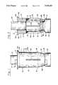
- FIG. 1is a side view of the bone rivet with the puller in place
- FIG. 2is a cross-sectional view of the rivet taken along the line 2--2 of FIG. 1;
- FIG. 3is a top view of FIG. 2;
- FIG. 4is a side view of the puller
- FIG. 5is a sectional view of a bone rivet place, through a hole in an attaching plate, in a hole in "hard” bone with the broken-off head of the puller;
- FIG. 6is a sectional view of a bone rivet in place through a hole in an attaching plate, in a hole in "soft" bone with the broken-off head of the puller;
- FIG. 7is a cross-sectional view through two sections of bone which have been broken, prepared with a recess for receiving an attaching plate, and prepared with holes to receive bone rivets;
- FIG. 8is a view similar to FIG. 7 showing an attaching plate positioned in the recess;
- FIG. 9is a view similar to FIG. 1 showing a bone rivet with a larger top flange with means to attach a suture;
- FIG. 10is a top view of FIG. 9;
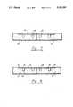
- FIG. 11is a cross-sectional view of a bone graft bridging a fracture, said bone graft being maintained in place by bone rivets of different lengths;
- FIGS. 12, 12A and 12Bshow bone rivets of different lengths with equal lengths of the lower annular portions
- FIG. 13is a cross-sectional view of a modified bone rivet
- FIG. 14is a view similar to FIG. 9 showing a modified bone rivet with holding barbs, and showing a suture threaded through the top flange;
- FIG. 15is a top view of FIG. 14.
- FIGS. 16, 16A and 16Bshow rivets of the same length with different lengths of the lower annular portions and upper annular portions.
- FIG. 1a bone rivet 2 is shown having a puller member 4 located therewith.
- Puller member 4comprises a puller head 20 and a puller rod 22.
- FIG. 2is a section taken lengthwise through the center of the bone rivet 2 showing details of the bone rivet 2 and puller member 4. Examples of the bone rivet 2 positioned in place in bones 3 of different hardness are shown in FIGS. 5 and 6.
- the bone rivet 2has an upper annular portion 20 with a head 6 formed at the top thereof.
- Said head 6has an annular flange 6A extending radially outwardly from around the top of the upper annular portion 10.
- a tapered surface 6Bextends from the outer edge of the annular flange 6A downwardly and inwardly to the outer surface 11 of the upper annular portion 10 for a purpose to be hereinafter described.
- the bone rivet 2has a lower annular portion 12 extending downwardly from the bottom of the upper annular portion 10.
- Lower annular portion 12has its outer surface 13 formed as an extension of outer surface 11 of upper annular portion 10.
- the thickness of the lower annular portion 12is smaller than the thickness of the upper annular portion 10 forming an annular step, or stop, 14, for a purpose to be hereinafter described.
- the lower part of the lower annular portion 12is bent inwardly at a circumferential bend line 16 and extends to the end forming an opening at the bottom of the lower annular portion 12 having an inner diameter which is approximately equal to that of the inner diameter of the upper annular portion 10.
- the puller rod 22extends upwardly through the inner diameter of the lower part of the annular portion 12 and the inner diameter of the upper annular portion 10.
- the lower end surface 18 of the lower annular portion 12is shown angled downwardly and outwardly from its inner edge. It is this surface which faces the slightly angled top surface 19 of the puller head 20.
- a plurality of slots 24is formed in the lower annular portion 12 forming lengthwise ribs 13A from the bottom of the upper annular portion 10, in line with the annular step, or stop, 14, to below the circumferential line 16 at which the lower annular portion 12 tapers inwardly leaving a solid tapered portion 26 at the lower end of the lower annular portion 12. It is this solid tapered portion 26 which ends in lower end surface 18.
- the top surface 19 of the puller head 20is formed, slightly angled downwardly from the puller rod 22, to aid in guiding the lower end surface 18 of the lower annular portion 12 outwardly if the bone 3 does not permit the top surface 19 of the puller head 20 to force the ribs 13A of the lower annular portion 12, between the slots 24, outwardly so as to project into the bone 3 as arms (see FIG. 6).
- the bottom of the solid tapered portion 26is expanded radially by the action of the top surface 19 of the puller head 20 against the bottom surface 18 to accept the puller head 20 within the lower annular portion 12 for movement upwardly to expand all of the lower annular portion 12 until it contacts the annular step, or stop, 14 (see FIG. 5).
- the puller rod 22is undercut at 30 to provide a weakened point along the puller rod 22 at which point the puller rod 22 will break when the top surface 19 of the puller head engages the step, or stop, 14, and the bone rivet 2 has been fixed in place in the bone 3.
- the twopart bone rivet assembly, the rivet 2 and puller member 4is formed of a bio-compatible material.
- the rivet 2was machined from a cylinder of titanium, and the puller member 4 was formed of cold forged titanium.
- the outer diameter of the puller rod 22 and the inner diameter of the end of the rivet 2are sized for an interference fit so that the rivet 2 and puller member 4 remain as one unit, or assembly, before use.
- Other meanscan be used to maintain a rivet 2 and puller member 4 together, if desired, such as between the upper annular portion 10 of the rivet 2 and the puller rod 22.
- a surgical instrumentis placed over the free end of the puller rod 22 and placed against the head 6 of the bone rivet 2.
- the instrumentgrasps the puller rod 22 and pulls it upwardly to react with the lower portion 12 of the bone rivet 2.
- the reaction of the top surface 19 of the puller head 20 against the lower end surface 18 of the lower annular portion 12deforms the lengthwise ribs 13A of the lower annular portion 12 differently, depending on the structure of the bone 3 being operated on.
- FIGS. 5 and 6where in FIG. 5, the bone rivet 2 is in place in a hole in "hard” bone where the lengthwise ribs 13A of the lower annular portion 12 are merely radially cylindrically expanded without having a radial deformation form at a circumferential line 16 and enter the bone 3.
- the top surface 19 of the puller head 20forces the solid tapered portion 26 outwardly and compresses it in the bone 3 and moves upwardly to compress all of the lengthwise ribs 13A of the lower annular portion 12 in the bone 3.
- the bone rivet 2is in place in a hole in "soft" bone, where the lengthwise ribs 13A of the lower annular portion 12 have been forced radially outward by the top surface 19 at the circumferential line 16 to enter the bone 3.
- Other meanscan be used to start bending at a desired location such as by an undercut section or locally thinned section (see FIG. 13). It can be seen that the plurality of slots 24 will permit a plurality of ribs 13A to extend as arms outwardly.
- hard and “soft” bones 3have been discussed as examples, it is to be understood that the hardness of a bone can lie anywhere in the range between a “hard” bone which permits only a radial expansion of the lower annular portion 12 of the bone rivet into the bone 3, and a “soft” bone which permits the lower annular portion 12 to be bent and extend into the bone 3; all expansions providing the necessary holding strength.
- FIGS. 12A, 12B and 12CThe location of the expanded portion of the rivet 2 below the surface of the bone is determined by the length of the upper annular portion 10.
- Bone rivet assemblies of bone rivet 2 and puller member 4 having different lengthsare shown in FIGS. 12A, 12B and 12C, and shown in use in a bone graft in FIG. 11.
- a plate 8is placed across the fracture, or between the bone fragments; holes 9 are placed in the plate on each side of the fracture and a hole 15 is drilled in the bone 3 aligned with each hole 9.
- Holes 9can have tapered sides to receive a rivet having a tapered surface 6B for a flush installation.
- a rivet assembly, rivet 2 and puller member 4are inserted through each hole 9 into its aligned hole 15 and pulled to connect the plate 8 to the bone 3.
- a recess 21is made in bone being attached to receive the plate 8 (see FIGS. 7 and 8).
- the upper annular portion 10 of the rivet 2be of such a length that the top of the "holding” expansion of the rivet 2 is formed below the surface of the bone to obtain the proper holding location.
- This lengthplaces the annular stop 14 below the surface layer of the bone to form the top of the "holding” expansion.
- the puller head 20when in position against annular stop 14, will hold the top of the ribs 13A outwardly in their expanded position, as shown in FIG. 5, or in their radially extended position, as shown in FIG. 6. This is also true of intermediate positions. This positioning of puller head 20 aids in preventing withdrawal of the rivet 2.
- FIG. 9shows a bone rivet device with a rivet 2A having an enlarged top 6C. Means are provided on top 6C to attach a suture.
- a single suture 42can be affixed to one hole 40 by being tied as in FIG. 9.
- a suture 42can be threaded through two holes 40 from one side making two suture ends available.
- a barb, or projection, 27,can be provided on one or more ribs 13A to aid in maintaining the rivet 2 in place (see FIG. 14).
- FIG. 11shows a bone 3A held in position to form a bone graft on a bone 3.
- Bone rivets 2of different lengths are used to place the step, or stop, 14 at a proper location at which to expand the rivet 2. The proper location is determined by the surgeon performing the operation.
- FIG. 13is a modification of a rivet 2 in which undercut sections 17 on ribs 13A provide a weakened location which would permit the ribs 13A to bend outwardly if the wall of the hole in which the rivet is located was "soft" enough.
- Bone rivet assemblies having the same lengthare shown in FIGS. 16, 16A and 16B and have different lengths of upper annular portion 10 and different lengths of lower annular portion 12 for use in controlling the area of expansion.
- the projection of ribs 13A into the "soft" bone 3forms arms of various shapes with the bend starting at circumferential line 16 depending on the density of the bone.
- the puller head 20bends the end of the solid tapered portion 26 inwardly and pulls within the end of the rivet 2 for the top surface 19 to engage the stop 14 and limit the expansion of the rivet.
Landscapes
- Health & Medical Sciences (AREA)
- Engineering & Computer Science (AREA)
- Life Sciences & Earth Sciences (AREA)
- Orthopedic Medicine & Surgery (AREA)
- Surgery (AREA)
- Public Health (AREA)
- General Health & Medical Sciences (AREA)
- Heart & Thoracic Surgery (AREA)
- Biomedical Technology (AREA)
- Veterinary Medicine (AREA)
- Animal Behavior & Ethology (AREA)
- Rheumatology (AREA)
- Nuclear Medicine, Radiotherapy & Molecular Imaging (AREA)
- Molecular Biology (AREA)
- Medical Informatics (AREA)
- General Engineering & Computer Science (AREA)
- Rehabilitation Therapy (AREA)
- Cardiology (AREA)
- Oral & Maxillofacial Surgery (AREA)
- Transplantation (AREA)
- Vascular Medicine (AREA)
- Mechanical Engineering (AREA)
- Neurology (AREA)
- Surgical Instruments (AREA)
Abstract
Description
The invention relates to a device for attaching metallic or synthetic plates and sutures to bone.
The most common fastener used in the reconstruction of fracture fragments in the human body is a screw. Screws of various types are used to directly hold fragments together, hold plates onto bone, and to act as anchors for the attachment of tendons and grafts of various types. Screws have certain disadvantages. In soft bone, they gain little purchase; in extremely thin bone, such as about the face, few threads gain purchase for adequate fixation. With the advent of extremely small bone plates for fracture and reconstructive surgical procedures, the screws are so small that just handling them and keeping them on a screwdriver can be difficult. Screws also require a significant amount of time to insert, especially if the hole has to be threaded first.
Various types of "blind" rivets are commonly used in industry. Most of them consist of two parts: a puller and the rivet body. The puller causes a deformation of the rivet body as it is moved in a linear direction. The expansion deformity of the rivet body continues until the expanded area reaches either the rivet head or the material into which the rivet is placed. These types of fasteners work well in sheet metal as the material has sufficient strength to resist further deformation of the rivet body and tight fixation, as well as breakaway of the puller shaft is accomplished quite easily. Unfortunately, these designs do not work well in the human body, as bone is not strong enough to stop the progression of the widened rivet body before it contacts the rivet head.
Patents related to the subject matter are the following: U.S. Pat. Nos. 1,105,105; 2,494,229; and 4,590,928.
The object of the present invention is to create a rivet fastener which will be effective for attachment in all types of bone and which will contribute significantly to the ease and rapidity of the procedure. To gain maximum expansion of the rivet body, the body is slotted longitudinally with the bottom portion tapered inwardly so that when it is forced to expand by a puller head, it will form radial wings, or arms, which will extend into soft bone, but just expand radially without forming wings, or arms, in harder bone. The wings, or arms, are forced to be created at a distance below the surface of the bone as determined by a tapered-in portion in the rivet body. Local thinning out or notching the rivet wall results in a similar rivet deformation. Complete deformation of the rivet body to the rivet head is prevented by a puller head stop. The design creates a "blind" rivet which is extremely effective for attaching objects to bone.
Another object of the invention is to provide a suture attachment to bone. This can be used for transplantation of tendons, re-attachment of muscles, and basically any needed fixation to bone.
Besides the intended application in the medical field, which requires the use of bio-compatible metals to be used exclusively, there is also a potential application in industry, where a variety of metals can be used to optimize specific requirements for fastening metals, plastics and wood. A combination of different metals and rivet geometry variations (i.e. steel puller and aluminum rivet) can be used to obtain modified rivet behavior to satisfy industrial applications.
FIG. 1 is a side view of the bone rivet with the puller in place;
FIG. 2 is a cross-sectional view of the rivet taken along theline 2--2 of FIG. 1;
FIG. 3 is a top view of FIG. 2;
FIG. 4 is a side view of the puller;
FIG. 5 is a sectional view of a bone rivet place, through a hole in an attaching plate, in a hole in "hard" bone with the broken-off head of the puller;
FIG. 6 is a sectional view of a bone rivet in place through a hole in an attaching plate, in a hole in "soft" bone with the broken-off head of the puller;
FIG. 7 is a cross-sectional view through two sections of bone which have been broken, prepared with a recess for receiving an attaching plate, and prepared with holes to receive bone rivets;
FIG. 8 is a view similar to FIG. 7 showing an attaching plate positioned in the recess;
FIG. 9 is a view similar to FIG. 1 showing a bone rivet with a larger top flange with means to attach a suture;
FIG. 10 is a top view of FIG. 9;
FIG. 11 is a cross-sectional view of a bone graft bridging a fracture, said bone graft being maintained in place by bone rivets of different lengths;
FIGS. 12, 12A and 12B show bone rivets of different lengths with equal lengths of the lower annular portions;
FIG. 13 is a cross-sectional view of a modified bone rivet;
FIG. 14 is a view similar to FIG. 9 showing a modified bone rivet with holding barbs, and showing a suture threaded through the top flange;
FIG. 15 is a top view of FIG. 14; and
FIGS. 16, 16A and 16B show rivets of the same length with different lengths of the lower annular portions and upper annular portions.
Referring to FIG. 1, abone rivet 2 is shown having apuller member 4 located therewith.Puller member 4 comprises apuller head 20 and apuller rod 22. FIG. 2 is a section taken lengthwise through the center of thebone rivet 2 showing details of thebone rivet 2 andpuller member 4. Examples of thebone rivet 2 positioned in place inbones 3 of different hardness are shown in FIGS. 5 and 6.
Thebone rivet 2 has an upperannular portion 20 with ahead 6 formed at the top thereof. Saidhead 6 has anannular flange 6A extending radially outwardly from around the top of the upperannular portion 10. Atapered surface 6B extends from the outer edge of theannular flange 6A downwardly and inwardly to the outer surface 11 of the upperannular portion 10 for a purpose to be hereinafter described.
Thebone rivet 2 has a lowerannular portion 12 extending downwardly from the bottom of the upperannular portion 10. Lowerannular portion 12 has itsouter surface 13 formed as an extension of outer surface 11 of upperannular portion 10. The thickness of the lowerannular portion 12 is smaller than the thickness of the upperannular portion 10 forming an annular step, or stop, 14, for a purpose to be hereinafter described.
The lower part of the lowerannular portion 12 is bent inwardly at acircumferential bend line 16 and extends to the end forming an opening at the bottom of the lowerannular portion 12 having an inner diameter which is approximately equal to that of the inner diameter of the upperannular portion 10. Thepuller rod 22 extends upwardly through the inner diameter of the lower part of theannular portion 12 and the inner diameter of the upperannular portion 10.
It is noted that thelower end surface 18 of the lowerannular portion 12 is shown angled downwardly and outwardly from its inner edge. It is this surface which faces the slightly angledtop surface 19 of thepuller head 20. A plurality ofslots 24 is formed in the lowerannular portion 12 forming lengthwiseribs 13A from the bottom of the upperannular portion 10, in line with the annular step, or stop, 14, to below thecircumferential line 16 at which the lowerannular portion 12 tapers inwardly leaving a solidtapered portion 26 at the lower end of the lowerannular portion 12. It is this solidtapered portion 26 which ends inlower end surface 18. Thetop surface 19 of thepuller head 20 is formed, slightly angled downwardly from thepuller rod 22, to aid in guiding thelower end surface 18 of the lowerannular portion 12 outwardly if thebone 3 does not permit thetop surface 19 of thepuller head 20 to force theribs 13A of the lowerannular portion 12, between theslots 24, outwardly so as to project into thebone 3 as arms (see FIG. 6). If bone resistance prevents the lowerannular portion 12 from bending so that theribs 13A enter the bone as radially extending arms, the bottom of the solidtapered portion 26 is expanded radially by the action of thetop surface 19 of thepuller head 20 against thebottom surface 18 to accept thepuller head 20 within the lowerannular portion 12 for movement upwardly to expand all of the lowerannular portion 12 until it contacts the annular step, or stop, 14 (see FIG. 5).
Thepuller rod 22 is undercut at 30 to provide a weakened point along thepuller rod 22 at which point thepuller rod 22 will break when thetop surface 19 of the puller head engages the step, or stop, 14, and thebone rivet 2 has been fixed in place in thebone 3. The twopart bone rivet assembly, therivet 2 andpuller member 4, is formed of a bio-compatible material. In a bone rivet assembly made, therivet 2 was machined from a cylinder of titanium, and thepuller member 4 was formed of cold forged titanium. The outer diameter of thepuller rod 22 and the inner diameter of the end of therivet 2 are sized for an interference fit so that therivet 2 andpuller member 4 remain as one unit, or assembly, before use. Other means can be used to maintain arivet 2 andpuller member 4 together, if desired, such as between the upperannular portion 10 of therivet 2 and thepuller rod 22.
In use, a surgical instrument is placed over the free end of thepuller rod 22 and placed against thehead 6 of thebone rivet 2. The instrument then grasps thepuller rod 22 and pulls it upwardly to react with thelower portion 12 of thebone rivet 2. The reaction of thetop surface 19 of thepuller head 20 against thelower end surface 18 of the lowerannular portion 12 deforms thelengthwise ribs 13A of the lowerannular portion 12 differently, depending on the structure of thebone 3 being operated on.
This is shown in FIGS. 5 and 6, where in FIG. 5, thebone rivet 2 is in place in a hole in "hard" bone where thelengthwise ribs 13A of the lowerannular portion 12 are merely radially cylindrically expanded without having a radial deformation form at acircumferential line 16 and enter thebone 3. Thetop surface 19 of thepuller head 20 forces the solid taperedportion 26 outwardly and compresses it in thebone 3 and moves upwardly to compress all of thelengthwise ribs 13A of the lowerannular portion 12 in thebone 3.
In FIG. 6, thebone rivet 2 is in place in a hole in "soft" bone, where thelengthwise ribs 13A of the lowerannular portion 12 have been forced radially outward by thetop surface 19 at thecircumferential line 16 to enter thebone 3. Other means can be used to start bending at a desired location such as by an undercut section or locally thinned section (see FIG. 13). It can be seen that the plurality ofslots 24 will permit a plurality ofribs 13A to extend as arms outwardly.
While "hard" and "soft"bones 3 have been discussed as examples, it is to be understood that the hardness of a bone can lie anywhere in the range between a "hard" bone which permits only a radial expansion of the lowerannular portion 12 of the bone rivet into thebone 3, and a "soft" bone which permits the lowerannular portion 12 to be bent and extend into thebone 3; all expansions providing the necessary holding strength.
The location of the expanded portion of therivet 2 below the surface of the bone is determined by the length of the upperannular portion 10. Bone rivet assemblies ofbone rivet 2 andpuller member 4 having different lengths are shown in FIGS. 12A, 12B and 12C, and shown in use in a bone graft in FIG. 11.
With some fractures, or a pair of bone fragments, aplate 8 is placed across the fracture, or between the bone fragments;holes 9 are placed in the plate on each side of the fracture and ahole 15 is drilled in thebone 3 aligned with eachhole 9.Holes 9 can have tapered sides to receive a rivet having a taperedsurface 6B for a flush installation. A rivet assembly,rivet 2 andpuller member 4, are inserted through eachhole 9 into its alignedhole 15 and pulled to connect theplate 8 to thebone 3. In some instances, arecess 21 is made in bone being attached to receive the plate 8 (see FIGS. 7 and 8).
It is desirable that the upperannular portion 10 of therivet 2 be of such a length that the top of the "holding" expansion of therivet 2 is formed below the surface of the bone to obtain the proper holding location. This length places theannular stop 14 below the surface layer of the bone to form the top of the "holding" expansion. It can be seen that thepuller head 20, when in position againstannular stop 14, will hold the top of theribs 13A outwardly in their expanded position, as shown in FIG. 5, or in their radially extended position, as shown in FIG. 6. This is also true of intermediate positions. This positioning ofpuller head 20 aids in preventing withdrawal of therivet 2.
FIG. 9 shows a bone rivet device with arivet 2A having anenlarged top 6C. Means are provided on top 6C to attach a suture.
Fourholes 40 are placed around the top 6C to affix asuture 42. Asingle suture 42 can be affixed to onehole 40 by being tied as in FIG. 9. Asuture 42 can be threaded through twoholes 40 from one side making two suture ends available. A barb, or projection, 27, can be provided on one ormore ribs 13A to aid in maintaining therivet 2 in place (see FIG. 14).
FIG. 11 shows abone 3A held in position to form a bone graft on abone 3. Bone rivets 2 of different lengths are used to place the step, or stop, 14 at a proper location at which to expand therivet 2. The proper location is determined by the surgeon performing the operation.
FIG. 13 is a modification of arivet 2 in which undercutsections 17 onribs 13A provide a weakened location which would permit theribs 13A to bend outwardly if the wall of the hole in which the rivet is located was "soft" enough.
Bone rivet assemblies having the same length are shown in FIGS. 16, 16A and 16B and have different lengths of upperannular portion 10 and different lengths of lowerannular portion 12 for use in controlling the area of expansion.
As shown in FIG. 6, the projection ofribs 13A into the "soft"bone 3 forms arms of various shapes with the bend starting atcircumferential line 16 depending on the density of the bone. As the arms form, thepuller head 20 bends the end of the solid taperedportion 26 inwardly and pulls within the end of therivet 2 for thetop surface 19 to engage thestop 14 and limit the expansion of the rivet.
While the principles of the invention have now been made clear in an illustrative embodiment, it will become obvious to those skilled in the art that many modifications in arrangement are possible without departing from those principles. The appended claims are, therefore, intended to cover and embrace any such modifications, within the limits of the true spirit and scope of the invention.
Claims (9)
1. An expandable rivet for expanding in a hole, said rivet having a cylindrical body with an exterior surface for fitting in a hole, said cylindrical body having a top and a bottom, a radial projection means at the top of said cylindrical body for contacting the edge of a hole to control the extent the cylindrical body extends into a holes said cylindrical body having a longitudinal opening extending therethrough, a top portion of said cylindrical body having the opening with a first diameter for receiving a puller rod, a bottom portion of said cylindrical body below said top portion having the opening with a second diameter greater than the first diameter, said cylindrical body having an annular step facing downwardly where the two diameters of the opening meet forming a stop for a puller head, said bottom portion of said cylindrical body having a plurality of longitudinal slots therein extending between the exterior surface and the opening extending therethrough forming ribs, the lower part of said bottom portion being tapered inwardly to its end, a solid annular ring at the bottom of said tapered bottom portion connecting to the ribs, said solid annular ring having a bottom annular surface, said annular surface being tapered outwardly and downwardly for being contacted by a puller head for rivet expansion.
2. An expandable rivet assembly for expanding in a hole, a rivet having a cylindrical body with an exterior surface for fitting in a hole, said cylindrical body having a top and a bottom, a radial projection means at the top of said cylindrical body for contacting the edge of a hole to control the extent the cylindrical body extends into the hole, said cylindrical body having a longitudinal opening extending therethrough, a puller for expanding said rivet extending through said opening, said puller having a puller rod with a puller head, said puller rod extending above the top of said cylindrical body, said puller head being below the bottom of said cylindrical body, a top portion of said cylindrical body having the longitudinal opening with a first diameter receiving said puller rod with a slidable fit, a bottom portion of said cylindrical body below said top portion having the longitudinal opening with a second diameter greater than the first diameter, said cylindrical body having an annular step facing downwardly where the two diameters of the opening meet forming a stop for the puller head, said bottom portion of said cylindrical body having a plurality of longitudinal slots therein extending between the exterior surface and the opening extending therethrough forming ribs, said bottom portion of said cylindrical body having a bottom annular surface, said puller head having a third diameter greater than the second diameter of the opening, said puller head having a top surface for engaging and acting against said bottom annular surface of said cylindrical body to expand the exterior surface of the bottom portion of said cylindrical body outwardly when the puller rod is pulled upwardly, said stop for the puller head limiting the upward expansion of the rivet, the lower part of said bottom portion of said cylindrical body being tapered inwardly to its end.
3. An expandable rivet assembly as set forth in claim 2 including a solid annular ring at the bottom of said tapered bottom portion.
4. An expandable rivet assembly as set forth in claim 2 for expanding in a hole in material of varying density, said cylindrical body of said rivet having two ways to expand, one is to expand as radially extending arms into the material and the other is to expand radially as a larger cylinder compressing the material; when said puller head acts against said bottom annular surface of said cylindrical body to expand it, if the bottom portion of said cylindrical body is against material of low density said ribs will extend as arms into the material by the puller head; if the bottom portion of said cylindrical body is against material of high density said bottom portion of said cylindrical body will expand radially as a larger cylinder compressing the high density material by the puller head being pulled within said bottom portion of said cylindrical body to expand said bottom portion of said cylindrical body; said puller stopping expansion when it contacts said stop.
5. An expandable rivet assembly as set forth in claim 4 wherein the material is bone.
6. An expandable rivet for expanding in a hole, said rivet having a cylindrical body with an exterior surface for fitting in a hole, said cylindrical body having a top and a bottom, a radial projection means at the top of said cylindrical body for contacting the edge of a hole to control the extent the cylindrical body extends into a hole, said cylindrical body having a single longitudinal opening extending therethrough, a top portion of said cylindrical body having the single longitudinal opening with a first diameter for receiving a puller rod, a bottom portion of said cylindrical body below said top portion having the single longitudinal opening with a second diameter greater than the first diameter, said cylindrical body having an inner annular step facing downwardly where the two diameters of the single longitudinal opening meet forming a stop for a puller head, said bottom portion of said cylindrical body having a plurality of longitudinal slots therein extending between the exterior surface and the opening extending therethrough forming ribs, the lower part of said bottom portion of said cylindrical body being tapered inwardly to its end for contacting a puller head, a solid annular ring at the bottom of said tapered bottom portion connecting the ribs, said solid annular ring having a bottom annular surface, said annular surface being tapered for being contacted by a puller head for directing the tapered end of said annular ring radially.
7. An expandable rivet assembly as set forth in claim 6 wherein said hole is in bone.
8. An expandable rivet assembly as set forth in claim 6 wherein said annular surface is tapered outwardly and downwardly.
9. An expandable rivet for expanding in a hole, a rivet having a cylindrical body with an exterior surface for fitting in a hole, said cylindrical body having a top and a bottom, a radial projection means at the top of said cylindrical body to control the extent the cylindrical body extends into a hole, said cylindrical body having a longitudinal opening extending therethrough, a puller extending through said opening for expanding said rivet, said puller having a puller rod with a puller head, said puller rod extending above the top of said cylindrical body, said puller head being positioned below the bottom of said cylindrical body, a top portion of said cylindrical body having the longitudinal opening with a first diameter receiving said puller rod with a slidable fit, a bottom portion of said cylindrical body below said top portion having the longitudinal opening with a second diameter greater than the first diameter, said puller head having a top annular surface, said cylindrical body having an annular step facing downwardly in said longitudinal opening where the two diameters of the opening meet an upward annular stop for the top annular surface of the puller head, said cylindrical body below said top portion having a plurality of longitudinal slots therein extending between the exterior surface and the opening extending therethrough forming ribs, the lower part of said bottom portion of said cylindrical body being tapered inwardly to its end, said bottom portion of said cylindrical body having a bottom annular surface, said top annular surface of said puller head being aligned with said bottom annular surface of said cylindrical body for engaging and acting against said bottom annular surface to radially expand the ribs of the exterior surface of said cylindrical body outwardly when the puller rod is pulled upwardly, said annular stop for the puller head being aligned with said top annular surface of said puller head limiting the radial expansion of the rivet by limiting the upward pull of the puller head to below said annular stop.
Priority Applications (3)
| Application Number | Priority Date | Filing Date | Title |
|---|---|---|---|
| US07/889,477US5326205A (en) | 1992-05-27 | 1992-05-27 | Expandable rivet assembly |
| EP92630102AEP0571686A1 (en) | 1992-05-27 | 1992-11-27 | Rivet for attaching objects |
| US08/215,279US5501695A (en) | 1992-05-27 | 1994-03-21 | Fastener for attaching objects to bones |
Applications Claiming Priority (1)
| Application Number | Priority Date | Filing Date | Title |
|---|---|---|---|
| US07/889,477US5326205A (en) | 1992-05-27 | 1992-05-27 | Expandable rivet assembly |
Related Child Applications (1)
| Application Number | Title | Priority Date | Filing Date |
|---|---|---|---|
| US08/215,279Continuation-In-PartUS5501695A (en) | 1992-05-27 | 1994-03-21 | Fastener for attaching objects to bones |
Publications (1)
| Publication Number | Publication Date |
|---|---|
| US5326205Atrue US5326205A (en) | 1994-07-05 |
Family
ID=25395185
Family Applications (1)
| Application Number | Title | Priority Date | Filing Date |
|---|---|---|---|
| US07/889,477Expired - LifetimeUS5326205A (en) | 1992-05-27 | 1992-05-27 | Expandable rivet assembly |
Country Status (2)
| Country | Link |
|---|---|
| US (1) | US5326205A (en) |
| EP (1) | EP0571686A1 (en) |
Cited By (104)
| Publication number | Priority date | Publication date | Assignee | Title |
|---|---|---|---|---|
| US5643321A (en)* | 1994-11-10 | 1997-07-01 | Innovasive Devices | Suture anchor assembly and methods |
| US5649963A (en)* | 1994-11-10 | 1997-07-22 | Innovasive Devices, Inc. | Suture anchor assembly and methods |
| US5725529A (en)* | 1990-09-25 | 1998-03-10 | Innovasive Devices, Inc. | Bone fastener |
| US5814071A (en)* | 1994-11-10 | 1998-09-29 | Innovasive Devices, Inc. | Suture anchor assembly and methods |
| US5860978A (en)* | 1990-09-25 | 1999-01-19 | Innovasive Devices, Inc. | Methods and apparatus for preventing migration of sutures through transosseous tunnels |
| US5935129A (en)* | 1997-03-07 | 1999-08-10 | Innovasive Devices, Inc. | Methods and apparatus for anchoring objects to bone |
| US5980558A (en)* | 1997-09-30 | 1999-11-09 | Biomet Inc. | Suture anchor system |
| EP0998878A1 (en) | 1998-11-03 | 2000-05-10 | Ethicon, Inc. | Biocompatible absorbable rivets and pins for use in surgical procedures |
| US6146406A (en) | 1998-02-12 | 2000-11-14 | Smith & Nephew, Inc. | Bone anchor |
| US6168598B1 (en) | 1997-06-02 | 2001-01-02 | Jeannette Martello | Soft tissue securing anchor |
| US6319258B1 (en) | 1999-09-29 | 2001-11-20 | Ethicon, Inc. | Absorbable rivet/pin applier for use in surgical procedures |
| US6328758B1 (en)* | 1998-04-21 | 2001-12-11 | Tornier Sa | Suture anchor with reversible expansion |
| US6428550B1 (en)* | 1999-05-18 | 2002-08-06 | Cardica, Inc. | Sutureless closure and deployment system for connecting blood vessels |
| US6471713B1 (en) | 2000-11-13 | 2002-10-29 | Cardica, Inc. | System for deploying an anastomosis device and method of performing anastomosis |
| US6482210B1 (en) | 1998-11-12 | 2002-11-19 | Orthopaedic Biosystems, Ltd., Inc. | Soft tissue/ligament to bone fixation device with inserter |
| US6527794B1 (en) | 1999-08-10 | 2003-03-04 | Ethicon, Inc. | Self-locking suture anchor |
| US6537288B2 (en) | 1999-05-18 | 2003-03-25 | Cardica, Inc. | Implantable medical device such as an anastomosis device |
| US6540770B1 (en)* | 1998-04-21 | 2003-04-01 | Tornier Sa | Reversible fixation device for securing an implant in bone |
| US6582453B1 (en) | 2000-07-14 | 2003-06-24 | Opus Medical, Inc. | Method and apparatus for attaching connective tissues to bone using a suture anchoring device |
| US6616694B1 (en) | 1996-11-21 | 2003-09-09 | Ethicon, Inc. | Apparatus for anchoring autologous or artificial tendon grafts in bone |
| US6660008B1 (en) | 2001-06-07 | 2003-12-09 | Opus Medical, Inc. | Method and apparatus for attaching connective tissues to bone using a suture anchoring device |
| US6673088B1 (en) | 1999-05-18 | 2004-01-06 | Cardica, Inc. | Tissue punch |
| US6689153B1 (en) | 1999-04-16 | 2004-02-10 | Orthopaedic Biosystems Ltd, Inc. | Methods and apparatus for a coated anchoring device and/or suture |
| US6719769B2 (en) | 1999-11-15 | 2004-04-13 | Cardica, Inc. | Integrated anastomosis tool with graft vessel attachment device and cutting device |
| US20040073219A1 (en)* | 2002-10-15 | 2004-04-15 | Skiba Jeffry B. | Insertion instrument |
| US20040181234A1 (en)* | 2000-11-16 | 2004-09-16 | Mcdevitt Dennis | Apparatus and method for attaching soft tissue to bone |
| US6846313B1 (en) | 1998-11-03 | 2005-01-25 | Codman & Shurtleff, Inc. | One-piece biocompatible absorbable rivet and pin for use in surgical procedures |
| US20050089384A1 (en)* | 2003-10-22 | 2005-04-28 | Pratt Adam D. | Fastener with adhesive |
| US20050267325A1 (en)* | 2004-05-03 | 2005-12-01 | Ams Research Corporation | Surgical implants and related methods |
| US20060064094A1 (en)* | 1998-10-26 | 2006-03-23 | Expanding Orthopedics, Inc. | Expandable orthopedic device |
| US7048751B2 (en) | 2001-12-06 | 2006-05-23 | Cardica, Inc. | Implantable medical device such as an anastomosis device |
| US7074203B1 (en) | 1990-09-25 | 2006-07-11 | Depuy Mitek, Inc. | Bone anchor and deployment device therefor |
| US20060235413A1 (en)* | 2004-12-07 | 2006-10-19 | Arthrotek, Inc. | Expanding suture anchor having an actuator pin |
| US7144405B2 (en) | 1999-05-18 | 2006-12-05 | Cardica, Inc. | Tissue punch |
| US7247164B1 (en) | 1999-12-30 | 2007-07-24 | Arthrocare Corporation | Methods for attaching connective tissues to bone using a multi-component bone anchor |
| US20080281364A1 (en)* | 2007-05-08 | 2008-11-13 | Spineworks Medical, Inc. | Systems, devices and methods for stabilizing bone |
| US20080294204A1 (en)* | 2007-03-07 | 2008-11-27 | Spineworks Medical, Inc. | Systems, methods, and devices for soft tissue attachment to bone |
| US20090005782A1 (en)* | 2007-03-02 | 2009-01-01 | Chirico Paul E | Fracture Fixation System and Method |
| US20090012564A1 (en)* | 2007-03-07 | 2009-01-08 | Spineworks Medical, Inc. | Transdiscal interbody fusion device and method |
| US7556640B2 (en) | 2001-02-12 | 2009-07-07 | Arthrocare Corporation | Bone anchor device having toggle member for attaching connective tissues to bone |
| US20090216260A1 (en)* | 2008-02-20 | 2009-08-27 | Souza Alison M | Interlocking handle |
| US20090234398A1 (en)* | 2005-08-31 | 2009-09-17 | Chirico Paul E | Implantable devices and methods for treating micro-architecture deterioration of bone tissue |
| US20090259094A1 (en)* | 2005-04-26 | 2009-10-15 | Ams Research Corporation | Method and Apparatus for Prolapse Repair |
| US20090276048A1 (en)* | 2007-05-08 | 2009-11-05 | Chirico Paul E | Devices and method for bilateral support of a compression-fractured vertebral body |
| US7615061B2 (en) | 2006-02-28 | 2009-11-10 | Arthrocare Corporation | Bone anchor suture-loading system, method and apparatus |
| US20090299386A1 (en)* | 2004-12-07 | 2009-12-03 | Biomet Sports Medicine, Llc | Soft Tissue Rivet and Method of Use |
| US7637926B2 (en) | 2002-02-04 | 2009-12-29 | Arthrocare Corporation | Method and apparatus for attaching connective tissues to bone using a knotless suture anchoring device |
| US7674274B2 (en) | 2001-06-06 | 2010-03-09 | Arthrocare Corporation | Method and apparatus for attaching connective tissues to bone using a cortical bone anchoring device |
| US20100069913A1 (en)* | 2005-08-31 | 2010-03-18 | Chirico Paul E | Threaded bone filling material plunger |
| US7682374B2 (en) | 2003-10-21 | 2010-03-23 | Arthrocare Corporation | Knotless suture lock and bone anchor implant method |
| US20100168748A1 (en)* | 2008-07-16 | 2010-07-01 | Knopp Peter G | Morselizer |
| US20100217335A1 (en)* | 2008-12-31 | 2010-08-26 | Chirico Paul E | Self-expanding bone stabilization devices |
| US20100261955A1 (en)* | 2007-07-27 | 2010-10-14 | O'hern Jeffrey Michael | Pelvic floor treatments and related tools and implants |
| US20100298630A1 (en)* | 2007-12-07 | 2010-11-25 | Shawn Michael Wignall | Pelvic floor treatments and related tools and implants |
| US20110004258A1 (en)* | 2007-05-07 | 2011-01-06 | Biomet Sports Medicine, Llc | Fixation Device for Delivery of Biologic Material Between Soft Tissue and Bone |
| US7896907B2 (en) | 1999-07-23 | 2011-03-01 | Ethicon, Inc. | System and method for attaching soft tissue to bone |
| US20110144766A1 (en)* | 2008-06-19 | 2011-06-16 | Shreedhar Kale | Allograft Bone Plugs, Systems and Techniques |
| US7963972B2 (en) | 2007-09-12 | 2011-06-21 | Arthrocare Corporation | Implant and delivery system for soft tissue repair |
| US7976565B1 (en)* | 2004-12-07 | 2011-07-12 | Biomet Sports Medicine, Llc | Expanding suture anchor having an actuator pin |
| US8105343B2 (en) | 2008-06-30 | 2012-01-31 | Arthrocare Corporation | Independent suture tensioning and snaring apparatus |
| US8133258B2 (en) | 2006-08-03 | 2012-03-13 | Arthrocare Corporation | Method and apparatus for attaching connective tissues to bone using a knotless suture anchoring device |
| US8137381B2 (en) | 2007-04-25 | 2012-03-20 | Arthrocare Corporation | Knotless suture anchor having discrete polymer components and related methods |
| US8287538B2 (en) | 2008-01-14 | 2012-10-16 | Conventus Orthopaedics, Inc. | Apparatus and methods for fracture repair |
| US20130177365A1 (en)* | 2010-06-08 | 2013-07-11 | Stephan Schneider | Blind rivet and fastening arrangement with a blind rivet |
| US8496705B2 (en) | 1996-11-21 | 2013-07-30 | DePuy Mitek, LLCR | Method of anchoring autologous or artificial tendon grafts in bone |
| US8523902B2 (en) | 2009-01-30 | 2013-09-03 | Kfx Medical Corporation | System and method for attaching soft tissue to bone |
| US8657854B2 (en) | 2001-02-12 | 2014-02-25 | Arthrocare Corporation | Knotless suture anchoring device having deforming section to accommodate sutures of various diameters |
| US20140154025A1 (en)* | 2011-03-07 | 2014-06-05 | Aurelie Bergez | Expansion bushing dowel |
| US8906022B2 (en) | 2010-03-08 | 2014-12-09 | Conventus Orthopaedics, Inc. | Apparatus and methods for securing a bone implant |
| US8961518B2 (en) | 2010-01-20 | 2015-02-24 | Conventus Orthopaedics, Inc. | Apparatus and methods for bone access and cavity preparation |
| US9023083B2 (en) | 2012-01-27 | 2015-05-05 | Arthrocare Corporation | Method for soft tissue repair with free floating suture locking member |
| US9034014B2 (en) | 2012-01-27 | 2015-05-19 | Arthrocare Corporation | Free floating wedge suture anchor for soft tissue repair |
| US9044313B2 (en) | 2010-10-08 | 2015-06-02 | Kfx Medical Corporation | System and method for securing tissue to bone |
| US9138219B2 (en) | 2010-12-29 | 2015-09-22 | Tarsus Medical Inc. | Methods and devices for treating a syndesmosis injury |
| US9186133B2 (en) | 2001-12-06 | 2015-11-17 | Arthrocare Corporation | Bone anchor insertion device |
| US9198649B2 (en) | 2012-01-27 | 2015-12-01 | Arthrocare Corporation | Rotating locking member suture anchor and method for soft tissue repair |
| US9226742B2 (en) | 2012-01-27 | 2016-01-05 | Arthrocare Corporation | Restricted wedge suture anchor and method for soft tissue repair |
| US9364210B2 (en) | 2012-01-27 | 2016-06-14 | Arthrocare Corporation | Biased wedge suture anchor and method for soft tissue repair |
| US9463091B2 (en) | 2009-09-17 | 2016-10-11 | Ldr Medical | Intervertebral implant having extendable bone fixation members |
| US9521999B2 (en) | 2005-09-13 | 2016-12-20 | Arthrex, Inc. | Fully-threaded bioabsorbable suture anchor |
| US9526493B2 (en) | 1999-02-02 | 2016-12-27 | Arthrex, Inc. | Suture anchor with insert-molded rigid member |
| US9597194B2 (en) | 2005-09-23 | 2017-03-21 | Ldr Medical | Intervertebral disc prosthesis |
| US9622739B2 (en) | 2004-04-06 | 2017-04-18 | Arthrex, Inc. | Suture anchor |
| US9636101B2 (en) | 2011-09-01 | 2017-05-02 | Arthrocare Corporation | Bone anchor having an integrated stress isolator |
| US9713535B2 (en) | 2006-02-15 | 2017-07-25 | Ldr Medical | Transforaminal intersomatic cage for an intervertebral fusion graft and an instrument for implanting the cage |
| US9730739B2 (en) | 2010-01-15 | 2017-08-15 | Conventus Orthopaedics, Inc. | Rotary-rigid orthopaedic rod |
| US9750492B2 (en) | 2006-08-04 | 2017-09-05 | Depuy Mitek, Llc | Suture anchor system with tension relief mechanism |
| US9775597B2 (en) | 2011-10-04 | 2017-10-03 | Conmed Corporation | Dual expansion anchor |
| US9788825B2 (en) | 2006-08-04 | 2017-10-17 | Depuy Mitek, Llc | Suture anchor with relief mechanism |
| US9795485B2 (en) | 2007-06-08 | 2017-10-24 | Ldr Medical | Intersomatic cage, intervertebral prosthesis, anchoring device and implantation instruments |
| US9826970B2 (en) | 2009-10-13 | 2017-11-28 | Conmed Corporation | System and method for securing tissue to bone |
| US9833331B2 (en) | 2009-12-31 | 2017-12-05 | Ldr Medical | Anchoring device and system for an intervertebral implant, intervertebral implant and implantation instrument |
| US9855028B2 (en) | 2012-04-06 | 2018-01-02 | Arthrocare Corporation | Multi-suture knotless anchor for attaching tissue to bone and related method |
| CN107847249A (en)* | 2015-05-11 | 2018-03-27 | 普罗维登斯医疗技术公司 | Bone screws and implant delivery apparatus |
| US9925036B2 (en) | 2013-03-15 | 2018-03-27 | Conmed Corporation | System and method for securing tissue to bone |
| US9937050B2 (en) | 2013-05-16 | 2018-04-10 | Ldr Medical | Vertebral implant, vertebral fastening device of the implant and implant instrumentation |
| US9968349B2 (en) | 2011-04-13 | 2018-05-15 | Conmed Corporation | System and method for securing tissue to bone |
| US10022132B2 (en) | 2013-12-12 | 2018-07-17 | Conventus Orthopaedics, Inc. | Tissue displacement tools and methods |
| US10149751B2 (en) | 2013-03-14 | 2018-12-11 | Conmed Corporation | Tissue capturing bone anchor |
| US10478310B2 (en) | 2014-05-06 | 2019-11-19 | Ldr Medical, S.A.S. | Vertebral implant, device for vertebral attachment of the implant and instrumentation for implantation thereof |
| US20200345341A1 (en)* | 2008-09-08 | 2020-11-05 | Howmedica Osteonics Corp. | Knotless Suture Anchor for Soft Tissue Repair and Method of Use |
| US10918426B2 (en) | 2017-07-04 | 2021-02-16 | Conventus Orthopaedics, Inc. | Apparatus and methods for treatment of a bone |
| US11596419B2 (en) | 2017-03-09 | 2023-03-07 | Flower Orthopedics Corporation | Plating depth gauge and countersink instrument |
| US11957598B2 (en) | 2004-02-04 | 2024-04-16 | Ldr Medical | Intervertebral disc prosthesis |
Families Citing this family (5)
| Publication number | Priority date | Publication date | Assignee | Title |
|---|---|---|---|---|
| US5843127A (en)* | 1994-08-22 | 1998-12-01 | Le Medical Technologies, Inc. | Fixation device and method for installing same |
| FR2731610B1 (en)* | 1995-03-16 | 1997-06-20 | Amp Dev | ANCHOR FOR INSERTION INTO A BONE CAVITY. |
| FR2738142B1 (en)* | 1995-09-06 | 1998-01-30 | Cedior | ANCHORING DEVICE FOR MUSCLE OR TENSIONER REINSERTION |
| US7083638B2 (en)* | 2001-02-12 | 2006-08-01 | Arthrocare Corporation | Method and apparatus for attaching connective tissues to bone using a knotless suture anchoring device |
| AU2002360783A1 (en)* | 2001-12-27 | 2003-07-24 | Osteotech Inc. | Orthopedic/neurosurgical system and method for securing vertebral bone facets |
Citations (8)
| Publication number | Priority date | Publication date | Assignee | Title |
|---|---|---|---|---|
| US3143916A (en)* | 1962-04-03 | 1964-08-11 | A A Rice Inc | Collapsible self-anchoring device |
| US3779239A (en)* | 1971-03-13 | 1973-12-18 | Fischer Artur | Connector for fractured bones |
| US3896504A (en)* | 1972-10-14 | 1975-07-29 | Artur Fischer | Hip joint prosthesis |
| US4355934A (en)* | 1979-09-28 | 1982-10-26 | Aerpat A.G. | Self-plugging blind rivet |
| US4580936A (en)* | 1983-03-07 | 1986-04-08 | Advel Limited | Blind rivet assembly |
| US4696610A (en)* | 1985-09-18 | 1987-09-29 | Wright Jewel L | Blind fastener |
| US4752168A (en)* | 1984-12-20 | 1988-06-21 | Hilti Aktiengesellschaft | Expansion dowel assembly |
| US5030050A (en)* | 1989-05-19 | 1991-07-09 | Ste. Ateliers De La Haute Garonne Et Auriol & Cie. | Blind riveting member, assembly process and assemblies obtained |
Family Cites Families (6)
| Publication number | Priority date | Publication date | Assignee | Title |
|---|---|---|---|---|
| GB891460A (en)* | 1957-03-25 | 1962-03-14 | Avdel Ltd | Improvements in or relating to blind rivets |
| GB1518084A (en)* | 1974-08-16 | 1978-07-19 | Avdel Ltd | Rivet |
| US4844673A (en)* | 1982-06-29 | 1989-07-04 | Huck Manufacturing Company | Lock spindle blind bolt with lock collar providing pin stop support |
| GB2163823A (en)* | 1984-08-31 | 1986-03-05 | Avdel Ltd | Self-plugging blind rivet |
| DE3841286A1 (en)* | 1988-12-08 | 1990-06-13 | Appel Hans Guenter | OSTEOSYNTHESE IMPLANTS |
| US5044850A (en)* | 1990-05-11 | 1991-09-03 | Avdel Corporation | Self plugging blind rivet |
- 1992
- 1992-05-27USUS07/889,477patent/US5326205A/ennot_activeExpired - Lifetime
- 1992-11-27EPEP92630102Apatent/EP0571686A1/ennot_activeWithdrawn
Patent Citations (8)
| Publication number | Priority date | Publication date | Assignee | Title |
|---|---|---|---|---|
| US3143916A (en)* | 1962-04-03 | 1964-08-11 | A A Rice Inc | Collapsible self-anchoring device |
| US3779239A (en)* | 1971-03-13 | 1973-12-18 | Fischer Artur | Connector for fractured bones |
| US3896504A (en)* | 1972-10-14 | 1975-07-29 | Artur Fischer | Hip joint prosthesis |
| US4355934A (en)* | 1979-09-28 | 1982-10-26 | Aerpat A.G. | Self-plugging blind rivet |
| US4580936A (en)* | 1983-03-07 | 1986-04-08 | Advel Limited | Blind rivet assembly |
| US4752168A (en)* | 1984-12-20 | 1988-06-21 | Hilti Aktiengesellschaft | Expansion dowel assembly |
| US4696610A (en)* | 1985-09-18 | 1987-09-29 | Wright Jewel L | Blind fastener |
| US5030050A (en)* | 1989-05-19 | 1991-07-09 | Ste. Ateliers De La Haute Garonne Et Auriol & Cie. | Blind riveting member, assembly process and assemblies obtained |
Cited By (195)
| Publication number | Priority date | Publication date | Assignee | Title |
|---|---|---|---|---|
| US7651495B2 (en) | 1990-09-24 | 2010-01-26 | Ethicon, Inc. | Methods and apparatus for preventing migration of sutures through transosseous tunnels |
| US20100100128A1 (en)* | 1990-09-24 | 2010-04-22 | Ethicon, Inc. | Methods and apparatus for preventing migration of sutures through transosseous tunnels |
| US8062295B2 (en) | 1990-09-24 | 2011-11-22 | Depuy Mitek, Inc. | Methods and apparatus for preventing migration of sutures through transosseous tunnels |
| US20050038437A1 (en)* | 1990-09-24 | 2005-02-17 | Ethicon, Inc. | Methods and apparatus for preventing migration of sutures through transosseous tunnels |
| US6302886B1 (en) | 1990-09-24 | 2001-10-16 | Innovasive Devices, Inc. | Method and apparatus for preventing migration of sutures through transosseous tunnels |
| US6830572B2 (en) | 1990-09-24 | 2004-12-14 | Depuy Mitex, Inc. | Methods and apparatus for preventing migration of sutures through transosseous tunnels |
| US5725529A (en)* | 1990-09-25 | 1998-03-10 | Innovasive Devices, Inc. | Bone fastener |
| US7074203B1 (en) | 1990-09-25 | 2006-07-11 | Depuy Mitek, Inc. | Bone anchor and deployment device therefor |
| US5860978A (en)* | 1990-09-25 | 1999-01-19 | Innovasive Devices, Inc. | Methods and apparatus for preventing migration of sutures through transosseous tunnels |
| US5643321A (en)* | 1994-11-10 | 1997-07-01 | Innovasive Devices | Suture anchor assembly and methods |
| US5814071A (en)* | 1994-11-10 | 1998-09-29 | Innovasive Devices, Inc. | Suture anchor assembly and methods |
| US5797963A (en)* | 1994-11-10 | 1998-08-25 | Innovasive Devices, Inc. | Suture anchor assembly and methods |
| US5649963A (en)* | 1994-11-10 | 1997-07-22 | Innovasive Devices, Inc. | Suture anchor assembly and methods |
| US7637949B2 (en) | 1996-11-21 | 2009-12-29 | Innovasive Devices, Inc. | Method for anchoring autologous or artificial tendon grafts in bone |
| US8100969B2 (en) | 1996-11-21 | 2012-01-24 | Depuy Mitek, Inc. | Methods for anchoring autologous or artificial tendon grafts using first and second bone anchors |
| US6616694B1 (en) | 1996-11-21 | 2003-09-09 | Ethicon, Inc. | Apparatus for anchoring autologous or artificial tendon grafts in bone |
| US20040097943A1 (en)* | 1996-11-21 | 2004-05-20 | Hart Rickey D. | Apparatus for anchoring autologous or artificial tendon grafts in bone |
| US20100121450A1 (en)* | 1996-11-21 | 2010-05-13 | Hart Rickey D | Method for anchoring autologous or artificial tendon grafts in bone |
| US8496705B2 (en) | 1996-11-21 | 2013-07-30 | DePuy Mitek, LLCR | Method of anchoring autologous or artificial tendon grafts in bone |
| US5935129A (en)* | 1997-03-07 | 1999-08-10 | Innovasive Devices, Inc. | Methods and apparatus for anchoring objects to bone |
| US6168598B1 (en) | 1997-06-02 | 2001-01-02 | Jeannette Martello | Soft tissue securing anchor |
| US5980558A (en)* | 1997-09-30 | 1999-11-09 | Biomet Inc. | Suture anchor system |
| US6146406A (en) | 1998-02-12 | 2000-11-14 | Smith & Nephew, Inc. | Bone anchor |
| US6328758B1 (en)* | 1998-04-21 | 2001-12-11 | Tornier Sa | Suture anchor with reversible expansion |
| US6540770B1 (en)* | 1998-04-21 | 2003-04-01 | Tornier Sa | Reversible fixation device for securing an implant in bone |
| US7601152B2 (en) | 1998-10-26 | 2009-10-13 | Expanding Orthopedics, Inc. | Expandable orthopedic device |
| US20060084998A1 (en)* | 1998-10-26 | 2006-04-20 | Expanding Orthopedics, Inc. | Expandable orthopedic device |
| US7670339B2 (en)* | 1998-10-26 | 2010-03-02 | Expanding Orthopedics, Inc. | Expandable orthopedic device |
| US20060064094A1 (en)* | 1998-10-26 | 2006-03-23 | Expanding Orthopedics, Inc. | Expandable orthopedic device |
| US6241732B1 (en) | 1998-11-03 | 2001-06-05 | David W. Overaker | Biocompatible absorbable rivets and pins for use in surgical procedures |
| US6846313B1 (en) | 1998-11-03 | 2005-01-25 | Codman & Shurtleff, Inc. | One-piece biocompatible absorbable rivet and pin for use in surgical procedures |
| EP0998878A1 (en) | 1998-11-03 | 2000-05-10 | Ethicon, Inc. | Biocompatible absorbable rivets and pins for use in surgical procedures |
| US6482210B1 (en) | 1998-11-12 | 2002-11-19 | Orthopaedic Biosystems, Ltd., Inc. | Soft tissue/ligament to bone fixation device with inserter |
| US9549726B2 (en) | 1999-02-02 | 2017-01-24 | Arthrex, Inc. | Suture anchor with insert-molded rigid member |
| US9526493B2 (en) | 1999-02-02 | 2016-12-27 | Arthrex, Inc. | Suture anchor with insert-molded rigid member |
| US6689153B1 (en) | 1999-04-16 | 2004-02-10 | Orthopaedic Biosystems Ltd, Inc. | Methods and apparatus for a coated anchoring device and/or suture |
| US6673088B1 (en) | 1999-05-18 | 2004-01-06 | Cardica, Inc. | Tissue punch |
| US7128749B1 (en) | 1999-05-18 | 2006-10-31 | Cardica, Inc. | Sutureless closure and deployment system for connecting blood vessels |
| US7309343B2 (en) | 1999-05-18 | 2007-12-18 | Cardica, Inc. | Method for cutting tissue |
| US7611523B2 (en) | 1999-05-18 | 2009-11-03 | Cardica, Inc. | Method for sutureless connection of vessels |
| US6893449B2 (en) | 1999-05-18 | 2005-05-17 | Cardica, Inc. | Device for cutting and anastomosing tissue |
| US7175637B2 (en) | 1999-05-18 | 2007-02-13 | Cardica, Inc. | Sutureless closure and deployment system for connecting blood vessels |
| US6652541B1 (en) | 1999-05-18 | 2003-11-25 | Cardica, Inc | Method of sutureless closure for connecting blood vessels |
| US7172608B2 (en) | 1999-05-18 | 2007-02-06 | Cardica, Inc. | Sutureless closure and deployment system for connecting blood vessels |
| US6537288B2 (en) | 1999-05-18 | 2003-03-25 | Cardica, Inc. | Implantable medical device such as an anastomosis device |
| US7468066B2 (en) | 1999-05-18 | 2008-12-23 | Cardica, Inc. | Trocar for use in deploying an anastomosis device and method of performing anastomosis |
| US7144405B2 (en) | 1999-05-18 | 2006-12-05 | Cardica, Inc. | Tissue punch |
| US6428550B1 (en)* | 1999-05-18 | 2002-08-06 | Cardica, Inc. | Sutureless closure and deployment system for connecting blood vessels |
| US7357807B2 (en) | 1999-05-18 | 2008-04-15 | Cardica, Inc. | Integrated anastomosis tool with graft vessel attachment device and cutting device |
| US6786914B1 (en) | 1999-05-18 | 2004-09-07 | Cardica, Inc. | Sutureless closure and deployment system for connecting blood vessels |
| US8491600B2 (en) | 1999-07-23 | 2013-07-23 | Depuy Mitek, Llc | System and method for attaching soft tissue to bone |
| US7896907B2 (en) | 1999-07-23 | 2011-03-01 | Ethicon, Inc. | System and method for attaching soft tissue to bone |
| US8518091B2 (en) | 1999-07-23 | 2013-08-27 | Depuy Mitek, Llc | System and method for attaching soft tissue to bone |
| US7081126B2 (en) | 1999-08-10 | 2006-07-25 | Ethicon, Inc. | Self-locking suture anchor |
| US9510816B2 (en) | 1999-08-10 | 2016-12-06 | Depuy Mitek, Llc | Self-locking suture anchor |
| US20050149122A1 (en)* | 1999-08-10 | 2005-07-07 | Mcdevitt Dennis | Self-locking suture anchor |
| US6660023B2 (en) | 1999-08-10 | 2003-12-09 | Ethicon, Inc. | Self-locking suture anchor |
| US20050090862A1 (en)* | 1999-08-10 | 2005-04-28 | Ethicon, Inc. | Self-locking suture anchor |
| US20090099598A1 (en)* | 1999-08-10 | 2009-04-16 | Depuy Mitek, Inc. | Self-locking suture anchor |
| US6527794B1 (en) | 1999-08-10 | 2003-03-04 | Ethicon, Inc. | Self-locking suture anchor |
| US6319258B1 (en) | 1999-09-29 | 2001-11-20 | Ethicon, Inc. | Absorbable rivet/pin applier for use in surgical procedures |
| US6719769B2 (en) | 1999-11-15 | 2004-04-13 | Cardica, Inc. | Integrated anastomosis tool with graft vessel attachment device and cutting device |
| US7247164B1 (en) | 1999-12-30 | 2007-07-24 | Arthrocare Corporation | Methods for attaching connective tissues to bone using a multi-component bone anchor |
| US8109966B2 (en) | 1999-12-30 | 2012-02-07 | Arthrocare Corporation | Methods for attaching connective tissues to bone using a multi-component anchor |
| US6582453B1 (en) | 2000-07-14 | 2003-06-24 | Opus Medical, Inc. | Method and apparatus for attaching connective tissues to bone using a suture anchoring device |
| US20030195564A1 (en)* | 2000-07-14 | 2003-10-16 | Opus Medical, Inc. | Method and apparatus for attaching connective tissues to bone using a suture anchoring device |
| US6471713B1 (en) | 2000-11-13 | 2002-10-29 | Cardica, Inc. | System for deploying an anastomosis device and method of performing anastomosis |
| US7867264B2 (en) | 2000-11-16 | 2011-01-11 | Ethicon, Inc. | Apparatus and method for attaching soft tissue to bone |
| US20040181234A1 (en)* | 2000-11-16 | 2004-09-16 | Mcdevitt Dennis | Apparatus and method for attaching soft tissue to bone |
| US9757114B2 (en) | 2000-11-16 | 2017-09-12 | Depuy Mitek, Llc | Apparatus and method for attaching soft tissue to bone |
| US8834543B2 (en) | 2000-11-16 | 2014-09-16 | Depuy Mitek, Llc | Apparatus and method for attaching soft tissue to bone |
| US8657854B2 (en) | 2001-02-12 | 2014-02-25 | Arthrocare Corporation | Knotless suture anchoring device having deforming section to accommodate sutures of various diameters |
| US7556640B2 (en) | 2001-02-12 | 2009-07-07 | Arthrocare Corporation | Bone anchor device having toggle member for attaching connective tissues to bone |
| US7695494B2 (en) | 2001-02-12 | 2010-04-13 | Arthrocare Corporation | Method and apparatus for attaching connective tissues to bone using a knotless suture anchoring device |
| US8444672B2 (en) | 2001-02-12 | 2013-05-21 | Arthrocare Corporation | Methods and devices for attaching connective tissues to bone using a knotless suture anchoring device |
| US8685060B2 (en) | 2001-02-12 | 2014-04-01 | Arthrocare Corporation | Methods and devices for attaching connective tissues to bone using a knotless suture anchoring device |
| US7674274B2 (en) | 2001-06-06 | 2010-03-09 | Arthrocare Corporation | Method and apparatus for attaching connective tissues to bone using a cortical bone anchoring device |
| US20040236336A1 (en)* | 2001-06-07 | 2004-11-25 | Opus Medical, Inc. | Method and apparatus for attaching connective tissues to bone using a suture anchoring device |
| US6660008B1 (en) | 2001-06-07 | 2003-12-09 | Opus Medical, Inc. | Method and apparatus for attaching connective tissues to bone using a suture anchoring device |
| US9186133B2 (en) | 2001-12-06 | 2015-11-17 | Arthrocare Corporation | Bone anchor insertion device |
| US7048751B2 (en) | 2001-12-06 | 2006-05-23 | Cardica, Inc. | Implantable medical device such as an anastomosis device |
| US7637926B2 (en) | 2002-02-04 | 2009-12-29 | Arthrocare Corporation | Method and apparatus for attaching connective tissues to bone using a knotless suture anchoring device |
| US20040073219A1 (en)* | 2002-10-15 | 2004-04-15 | Skiba Jeffry B. | Insertion instrument |
| US7682374B2 (en) | 2003-10-21 | 2010-03-23 | Arthrocare Corporation | Knotless suture lock and bone anchor implant method |
| US20050089384A1 (en)* | 2003-10-22 | 2005-04-28 | Pratt Adam D. | Fastener with adhesive |
| US11957598B2 (en) | 2004-02-04 | 2024-04-16 | Ldr Medical | Intervertebral disc prosthesis |
| US10537319B2 (en) | 2004-04-06 | 2020-01-21 | Arthrex, Inc. | Suture anchor |
| US9622739B2 (en) | 2004-04-06 | 2017-04-18 | Arthrex, Inc. | Suture anchor |
| US7722527B2 (en)* | 2004-05-03 | 2010-05-25 | Ams Research Corporation | Surgical implants and related methods |
| US20050267325A1 (en)* | 2004-05-03 | 2005-12-01 | Ams Research Corporation | Surgical implants and related methods |
| US20090299386A1 (en)* | 2004-12-07 | 2009-12-03 | Biomet Sports Medicine, Llc | Soft Tissue Rivet and Method of Use |
| US7976565B1 (en)* | 2004-12-07 | 2011-07-12 | Biomet Sports Medicine, Llc | Expanding suture anchor having an actuator pin |
| US8057524B2 (en) | 2004-12-07 | 2011-11-15 | Biomet Sports Medicine, Llc | Soft tissue rivet and method of use |
| US11357494B2 (en) | 2004-12-07 | 2022-06-14 | Biomet Manufacturing, Llc | Expanding suture anchor having an actuator pin |
| US8986345B2 (en) | 2004-12-07 | 2015-03-24 | Biomet Sports Medicine, Llc | Expanding suture anchor having an actuator pin |
| US12396716B2 (en) | 2004-12-07 | 2025-08-26 | Biomet Manufacturing, Llc | Expanding suture anchor having an actuator pin |
| US20060235413A1 (en)* | 2004-12-07 | 2006-10-19 | Arthrotek, Inc. | Expanding suture anchor having an actuator pin |
| US8109866B2 (en) | 2005-04-26 | 2012-02-07 | Ams Research Corporation | Method and apparatus for prolapse repair |
| US20090259094A1 (en)* | 2005-04-26 | 2009-10-15 | Ams Research Corporation | Method and Apparatus for Prolapse Repair |
| US8998923B2 (en) | 2005-08-31 | 2015-04-07 | Spinealign Medical, Inc. | Threaded bone filling material plunger |
| US20090234398A1 (en)* | 2005-08-31 | 2009-09-17 | Chirico Paul E | Implantable devices and methods for treating micro-architecture deterioration of bone tissue |
| US20100069913A1 (en)* | 2005-08-31 | 2010-03-18 | Chirico Paul E | Threaded bone filling material plunger |
| US10595847B2 (en) | 2005-09-13 | 2020-03-24 | Arthrex, Inc. | Fully-threaded bioabsorbable suture anchor |
| US11324493B2 (en) | 2005-09-13 | 2022-05-10 | Arthrex, Inc. | Fully-threaded bioabsorbable suture anchor |
| US9521999B2 (en) | 2005-09-13 | 2016-12-20 | Arthrex, Inc. | Fully-threaded bioabsorbable suture anchor |
| US12064104B2 (en) | 2005-09-13 | 2024-08-20 | Arthrex, Inc. | Fully-threaded bioabsorbable suture anchor |
| US9597194B2 (en) | 2005-09-23 | 2017-03-21 | Ldr Medical | Intervertebral disc prosthesis |
| US10492919B2 (en) | 2005-09-23 | 2019-12-03 | Ldr Medical | Intervertebral disc prosthesis |
| US11872138B2 (en) | 2005-09-23 | 2024-01-16 | Ldr Medical | Intervertebral disc prosthesis |
| US10758363B2 (en) | 2006-02-15 | 2020-09-01 | Ldr Medical | Transforaminal intersomatic cage for an intervertebral fusion graft and an instrument for implanting the cage |
| US9713535B2 (en) | 2006-02-15 | 2017-07-25 | Ldr Medical | Transforaminal intersomatic cage for an intervertebral fusion graft and an instrument for implanting the cage |
| US7615061B2 (en) | 2006-02-28 | 2009-11-10 | Arthrocare Corporation | Bone anchor suture-loading system, method and apparatus |
| US8133258B2 (en) | 2006-08-03 | 2012-03-13 | Arthrocare Corporation | Method and apparatus for attaching connective tissues to bone using a knotless suture anchoring device |
| US8317829B2 (en) | 2006-08-03 | 2012-11-27 | Arthrocare Corporation | Method and apparatus for attaching connective tissues to bone using a knotless suture anchoring device |
| US9750492B2 (en) | 2006-08-04 | 2017-09-05 | Depuy Mitek, Llc | Suture anchor system with tension relief mechanism |
| US10813633B2 (en) | 2006-08-04 | 2020-10-27 | DePuy Synthes Products, Inc. | Suture anchor system with tension relief mechanism |
| US10939902B2 (en) | 2006-08-04 | 2021-03-09 | DePuy Synthes Products, Inc. | Suture anchor with relief mechanism |
| US9788825B2 (en) | 2006-08-04 | 2017-10-17 | Depuy Mitek, Llc | Suture anchor with relief mechanism |
| US20090005782A1 (en)* | 2007-03-02 | 2009-01-01 | Chirico Paul E | Fracture Fixation System and Method |
| US20080294204A1 (en)* | 2007-03-07 | 2008-11-27 | Spineworks Medical, Inc. | Systems, methods, and devices for soft tissue attachment to bone |
| US20090012564A1 (en)* | 2007-03-07 | 2009-01-08 | Spineworks Medical, Inc. | Transdiscal interbody fusion device and method |
| US8137381B2 (en) | 2007-04-25 | 2012-03-20 | Arthrocare Corporation | Knotless suture anchor having discrete polymer components and related methods |
| US8939983B2 (en) | 2007-05-07 | 2015-01-27 | Biomet Sports Medicine, Llc | Fixation device for delivery of biological material between soft tissue and bone |
| US9439645B2 (en) | 2007-05-07 | 2016-09-13 | Biomet Sports Medicine, Llc | Fixation device for delivery of biologic material between soft tissue and bone |
| US20110004258A1 (en)* | 2007-05-07 | 2011-01-06 | Biomet Sports Medicine, Llc | Fixation Device for Delivery of Biologic Material Between Soft Tissue and Bone |
| US8574275B2 (en) | 2007-05-07 | 2013-11-05 | Biomet Sports Medicine, Llc | Fixation device for delivery of biologic material between soft tissue and bone |
| US20080281364A1 (en)* | 2007-05-08 | 2008-11-13 | Spineworks Medical, Inc. | Systems, devices and methods for stabilizing bone |
| US20090276048A1 (en)* | 2007-05-08 | 2009-11-05 | Chirico Paul E | Devices and method for bilateral support of a compression-fractured vertebral body |
| US10751187B2 (en) | 2007-06-08 | 2020-08-25 | Ldr Medical | Intersomatic cage, intervertebral prosthesis, anchoring device and implantation instruments |
| US9795485B2 (en) | 2007-06-08 | 2017-10-24 | Ldr Medical | Intersomatic cage, intervertebral prosthesis, anchoring device and implantation instruments |
| US10022210B2 (en) | 2007-07-27 | 2018-07-17 | Boston Scientific Scimed, Inc. | Pelvic floor treatments and related tools and implants |
| US8597173B2 (en) | 2007-07-27 | 2013-12-03 | Ams Research Corporation | Pelvic floor treatments and related tools and implants |
| US20100261955A1 (en)* | 2007-07-27 | 2010-10-14 | O'hern Jeffrey Michael | Pelvic floor treatments and related tools and implants |
| US8425536B2 (en) | 2007-09-12 | 2013-04-23 | Arthrocare Corporation | Implant and delivery system for soft tissue repair |
| US7963972B2 (en) | 2007-09-12 | 2011-06-21 | Arthrocare Corporation | Implant and delivery system for soft tissue repair |
| US20100298630A1 (en)* | 2007-12-07 | 2010-11-25 | Shawn Michael Wignall | Pelvic floor treatments and related tools and implants |
| US11399878B2 (en) | 2008-01-14 | 2022-08-02 | Conventus Orthopaedics, Inc. | Apparatus and methods for fracture repair |
| US9517093B2 (en) | 2008-01-14 | 2016-12-13 | Conventus Orthopaedics, Inc. | Apparatus and methods for fracture repair |
| US9788870B2 (en) | 2008-01-14 | 2017-10-17 | Conventus Orthopaedics, Inc. | Apparatus and methods for fracture repair |
| US8287538B2 (en) | 2008-01-14 | 2012-10-16 | Conventus Orthopaedics, Inc. | Apparatus and methods for fracture repair |
| US10603087B2 (en) | 2008-01-14 | 2020-03-31 | Conventus Orthopaedics, Inc. | Apparatus and methods for fracture repair |
| US20090216260A1 (en)* | 2008-02-20 | 2009-08-27 | Souza Alison M | Interlocking handle |
| US8840677B2 (en)* | 2008-06-19 | 2014-09-23 | DePuy Synthes Products, LLC | Allograft bone plugs, systems and techniques |
| US20110144766A1 (en)* | 2008-06-19 | 2011-06-16 | Shreedhar Kale | Allograft Bone Plugs, Systems and Techniques |
| US8617186B2 (en) | 2008-06-30 | 2013-12-31 | Arthrocare Corporation | Independent suture tensioning and snaring apparatus |
| US8834495B2 (en) | 2008-06-30 | 2014-09-16 | Arthrocare Corporation | Independent suture tensioning and snaring apparatus |
| US8828029B2 (en) | 2008-06-30 | 2014-09-09 | Arthrocare Corporation | Independent suture tensioning and snaring apparatus |
| US8105343B2 (en) | 2008-06-30 | 2012-01-31 | Arthrocare Corporation | Independent suture tensioning and snaring apparatus |
| US20100168748A1 (en)* | 2008-07-16 | 2010-07-01 | Knopp Peter G | Morselizer |
| US20200345341A1 (en)* | 2008-09-08 | 2020-11-05 | Howmedica Osteonics Corp. | Knotless Suture Anchor for Soft Tissue Repair and Method of Use |
| US20100217335A1 (en)* | 2008-12-31 | 2010-08-26 | Chirico Paul E | Self-expanding bone stabilization devices |
| US8523902B2 (en) | 2009-01-30 | 2013-09-03 | Kfx Medical Corporation | System and method for attaching soft tissue to bone |
| US9706984B2 (en) | 2009-01-30 | 2017-07-18 | Conmed Corporation | System and method for attaching soft tissue to bone |
| US9463091B2 (en) | 2009-09-17 | 2016-10-11 | Ldr Medical | Intervertebral implant having extendable bone fixation members |
| US9826970B2 (en) | 2009-10-13 | 2017-11-28 | Conmed Corporation | System and method for securing tissue to bone |
| US10531961B2 (en) | 2009-12-31 | 2020-01-14 | Ldr Medical | Anchoring device and system for an intervertebral implant, intervertebral implant and implantation instrument |
| US9833331B2 (en) | 2009-12-31 | 2017-12-05 | Ldr Medical | Anchoring device and system for an intervertebral implant, intervertebral implant and implantation instrument |
| US10195046B2 (en) | 2009-12-31 | 2019-02-05 | Ldr Medical | Instruments and methods for removing fixation devices from intervertebral implants |
| US11246715B2 (en) | 2009-12-31 | 2022-02-15 | Ldr Medical | Anchoring device and system for an intervertebral implant, intervertebral implant and implantation instrument |
| US9730739B2 (en) | 2010-01-15 | 2017-08-15 | Conventus Orthopaedics, Inc. | Rotary-rigid orthopaedic rod |
| US9848889B2 (en) | 2010-01-20 | 2017-12-26 | Conventus Orthopaedics, Inc. | Apparatus and methods for bone access and cavity preparation |
| US8961518B2 (en) | 2010-01-20 | 2015-02-24 | Conventus Orthopaedics, Inc. | Apparatus and methods for bone access and cavity preparation |
| US9993277B2 (en) | 2010-03-08 | 2018-06-12 | Conventus Orthopaedics, Inc. | Apparatus and methods for securing a bone implant |
| US8906022B2 (en) | 2010-03-08 | 2014-12-09 | Conventus Orthopaedics, Inc. | Apparatus and methods for securing a bone implant |
| US9334893B2 (en)* | 2010-06-08 | 2016-05-10 | Newfrey Llc | Blind rivet and fastening arrangement with a blind rivet |
| US20130177365A1 (en)* | 2010-06-08 | 2013-07-11 | Stephan Schneider | Blind rivet and fastening arrangement with a blind rivet |
| US10080647B2 (en) | 2010-10-08 | 2018-09-25 | Conmed Corporation | System and method for securing tissue to bone |
| US9044313B2 (en) | 2010-10-08 | 2015-06-02 | Kfx Medical Corporation | System and method for securing tissue to bone |
| US9138219B2 (en) | 2010-12-29 | 2015-09-22 | Tarsus Medical Inc. | Methods and devices for treating a syndesmosis injury |
| US20140154025A1 (en)* | 2011-03-07 | 2014-06-05 | Aurelie Bergez | Expansion bushing dowel |
| US9968349B2 (en) | 2011-04-13 | 2018-05-15 | Conmed Corporation | System and method for securing tissue to bone |
| US9636101B2 (en) | 2011-09-01 | 2017-05-02 | Arthrocare Corporation | Bone anchor having an integrated stress isolator |
| US9775597B2 (en) | 2011-10-04 | 2017-10-03 | Conmed Corporation | Dual expansion anchor |
| US9034014B2 (en) | 2012-01-27 | 2015-05-19 | Arthrocare Corporation | Free floating wedge suture anchor for soft tissue repair |
| US9226742B2 (en) | 2012-01-27 | 2016-01-05 | Arthrocare Corporation | Restricted wedge suture anchor and method for soft tissue repair |
| US9198649B2 (en) | 2012-01-27 | 2015-12-01 | Arthrocare Corporation | Rotating locking member suture anchor and method for soft tissue repair |
| US9364210B2 (en) | 2012-01-27 | 2016-06-14 | Arthrocare Corporation | Biased wedge suture anchor and method for soft tissue repair |
| US9023083B2 (en) | 2012-01-27 | 2015-05-05 | Arthrocare Corporation | Method for soft tissue repair with free floating suture locking member |
| US9855028B2 (en) | 2012-04-06 | 2018-01-02 | Arthrocare Corporation | Multi-suture knotless anchor for attaching tissue to bone and related method |
| US10149751B2 (en) | 2013-03-14 | 2018-12-11 | Conmed Corporation | Tissue capturing bone anchor |
| US11020218B2 (en) | 2013-03-14 | 2021-06-01 | Conmed Corporation | Tissue capturing bone anchor |
| US9925036B2 (en) | 2013-03-15 | 2018-03-27 | Conmed Corporation | System and method for securing tissue to bone |
| US11020217B2 (en) | 2013-03-15 | 2021-06-01 | Conmed Corporation | System and method for securing tissue to bone |
| US10154909B2 (en) | 2013-05-16 | 2018-12-18 | Ldr Medical | Vertebral implant, vertebral fastening device of the implant and implant instrumentation |
| US11633288B2 (en) | 2013-05-16 | 2023-04-25 | Ldr Medical | Vertebral implant, vertebral fastening device of the implant and implant instrumentation |
| US10779953B2 (en) | 2013-05-16 | 2020-09-22 | Ldr Medical | Vertebral implant, vertebral fastening device of the implant and implant instrumentation |
| US9974661B2 (en) | 2013-05-16 | 2018-05-22 | Ldr Medical | Vertebral implant, vertebral fastening device of the implant and implant instrumentation |
| US9937050B2 (en) | 2013-05-16 | 2018-04-10 | Ldr Medical | Vertebral implant, vertebral fastening device of the implant and implant instrumentation |
| US10076342B2 (en) | 2013-12-12 | 2018-09-18 | Conventus Orthopaedics, Inc. | Tissue displacement tools and methods |
| US10022132B2 (en) | 2013-12-12 | 2018-07-17 | Conventus Orthopaedics, Inc. | Tissue displacement tools and methods |
| US10478310B2 (en) | 2014-05-06 | 2019-11-19 | Ldr Medical, S.A.S. | Vertebral implant, device for vertebral attachment of the implant and instrumentation for implantation thereof |
| US10702391B2 (en) | 2014-05-06 | 2020-07-07 | Ldr Medical, S.A.S. | Vertebral implant, device for vertebral attachment of the implant and instrumentation for implantation thereof |
| CN107847249A (en)* | 2015-05-11 | 2018-03-27 | 普罗维登斯医疗技术公司 | Bone screws and implant delivery apparatus |
| US11596419B2 (en) | 2017-03-09 | 2023-03-07 | Flower Orthopedics Corporation | Plating depth gauge and countersink instrument |
| US10918426B2 (en) | 2017-07-04 | 2021-02-16 | Conventus Orthopaedics, Inc. | Apparatus and methods for treatment of a bone |
Also Published As
| Publication number | Publication date |
|---|---|
| EP0571686A1 (en) | 1993-12-01 |
Similar Documents
| Publication | Publication Date | Title |
|---|---|---|
| US5326205A (en) | Expandable rivet assembly | |
| US5501695A (en) | Fastener for attaching objects to bones | |
| CA1168482A (en) | Blind fastener device | |
| US6988862B1 (en) | Rivet, riveted joint structure riveting apparatus, and riveting method | |
| US4988247A (en) | Blind rivet and method of making same | |
| CA2333529C (en) | Bone anchor and deployment device therefor | |
| US4074608A (en) | Blind spacer fastener | |
| EP0235194B1 (en) | An interference fit blind fastener system | |
| AU610044B2 (en) | Blind rivet | |
| AU752826B2 (en) | Blind fastener | |
| US3369289A (en) | Die-draw blind rivet with deformable die and the method of setting same | |
| US20080086979A1 (en) | Method and apparatus for fastening steel framing members using helical features | |
| EP0448993B1 (en) | Dual-lock blind fastener | |
| EP1691087A2 (en) | Frangible Blind Rivet | |
| US4897003A (en) | Blind rivet | |
| US5288190A (en) | Expansion dowel assembly | |
| EP0497455A1 (en) | Self-plugging blind rivet | |
| EP0237957A2 (en) | Fastener for securing panels of composite materials | |
| AU647823B2 (en) | Anchoring device | |
| US4978266A (en) | Fastening element with expanding sleeve | |
| US5580202A (en) | Crowned solid rivet | |
| GB2124317A (en) | Blind rivet assembly | |
| EP0775837B1 (en) | Blind fastener with deformable sleeve | |
| GB2332722A (en) | Blind rivet with work hardened groove in shank | |
| JPS62167912A (en) | Impact expansion plug for fixing into conically inward expanded bag hole |
Legal Events
| Date | Code | Title | Description |
|---|---|---|---|
| STCF | Information on status: patent grant | Free format text:PATENTED CASE | |
| FPAY | Fee payment | Year of fee payment:4 | |
| FPAY | Fee payment | Year of fee payment:8 | |
| REMI | Maintenance fee reminder mailed | ||
| FPAY | Fee payment | Year of fee payment:12 | |
| SULP | Surcharge for late payment | Year of fee payment:11 |