US5325865A - Intracranial pressure monitoring system - Google Patents
Intracranial pressure monitoring systemDownload PDFInfo
- Publication number
- US5325865A US5325865AUS07/485,349US48534990AUS5325865AUS 5325865 AUS5325865 AUS 5325865AUS 48534990 AUS48534990 AUS 48534990AUS 5325865 AUS5325865 AUS 5325865A
- Authority
- US
- United States
- Prior art keywords
- signal
- optical
- temperature
- spectrum
- light source
- Prior art date
- Legal status (The legal status is an assumption and is not a legal conclusion. Google has not performed a legal analysis and makes no representation as to the accuracy of the status listed.)
- Expired - Lifetime
Links
- 238000012544monitoring processMethods0.000titledescription5
- 238000007917intracranial administrationMethods0.000titledescription2
- 230000003287optical effectEffects0.000claimsabstractdescription116
- 238000005259measurementMethods0.000claimsabstractdescription46
- 239000012530fluidSubstances0.000claimsabstractdescription41
- 238000001514detection methodMethods0.000claimsabstractdescription27
- 238000006243chemical reactionMethods0.000claimsabstractdescription10
- 238000001228spectrumMethods0.000claimsdescription122
- 230000008859changeEffects0.000claimsdescription57
- 230000004044responseEffects0.000claimsdescription23
- 230000003595spectral effectEffects0.000claimsdescription16
- 230000001419dependent effectEffects0.000claimsdescription11
- 238000000034methodMethods0.000claimsdescription7
- 238000009530blood pressure measurementMethods0.000claimsdescription2
- 230000000694effectsEffects0.000claimsdescription2
- 230000002401inhibitory effectEffects0.000claims5
- 230000003247decreasing effectEffects0.000claims2
- 238000001914filtrationMethods0.000claims2
- 230000001747exhibiting effectEffects0.000claims1
- 230000005284excitationEffects0.000abstractdescription39
- 230000006903response to temperatureEffects0.000abstractdescription2
- 239000004020conductorSubstances0.000description59
- 239000000835fiberSubstances0.000description10
- 230000006870functionEffects0.000description7
- QSHDDOUJBYECFT-UHFFFAOYSA-NmercuryChemical compound[Hg]QSHDDOUJBYECFT-UHFFFAOYSA-N0.000description6
- 229910052753mercuryInorganic materials0.000description6
- 239000003990capacitorSubstances0.000description5
- 238000010586diagramMethods0.000description4
- 238000005516engineering processMethods0.000description4
- 230000008901benefitEffects0.000description3
- 238000004458analytical methodMethods0.000description2
- 230000032683agingEffects0.000description1
- 230000003321amplificationEffects0.000description1
- 238000005452bendingMethods0.000description1
- 238000004891communicationMethods0.000description1
- 230000008878couplingEffects0.000description1
- 238000010168coupling processMethods0.000description1
- 238000005859coupling reactionMethods0.000description1
- 230000007812deficiencyEffects0.000description1
- 238000013461designMethods0.000description1
- 230000002706hydrostatic effectEffects0.000description1
- 230000010354integrationEffects0.000description1
- 239000007788liquidSubstances0.000description1
- 239000011159matrix materialSubstances0.000description1
- 238000012986modificationMethods0.000description1
- 230000004048modificationEffects0.000description1
- 238000003199nucleic acid amplification methodMethods0.000description1
- 239000013307optical fiberSubstances0.000description1
- 238000012545processingMethods0.000description1
- 230000001105regulatory effectEffects0.000description1
- 238000012552reviewMethods0.000description1
- 230000001360synchronised effectEffects0.000description1
- 238000012546transferMethods0.000description1
Images


Classifications
- G—PHYSICS
- G01—MEASURING; TESTING
- G01L—MEASURING FORCE, STRESS, TORQUE, WORK, MECHANICAL POWER, MECHANICAL EFFICIENCY, OR FLUID PRESSURE
- G01L9/00—Measuring steady of quasi-steady pressure of fluid or fluent solid material by electric or magnetic pressure-sensitive elements; Transmitting or indicating the displacement of mechanical pressure-sensitive elements, used to measure the steady or quasi-steady pressure of a fluid or fluent solid material, by electric or magnetic means
- G01L9/0041—Transmitting or indicating the displacement of flexible diaphragms
- G01L9/0076—Transmitting or indicating the displacement of flexible diaphragms using photoelectric means
- G01L9/0077—Transmitting or indicating the displacement of flexible diaphragms using photoelectric means for measuring reflected light
- A—HUMAN NECESSITIES
- A61—MEDICAL OR VETERINARY SCIENCE; HYGIENE
- A61B—DIAGNOSIS; SURGERY; IDENTIFICATION
- A61B5/00—Measuring for diagnostic purposes; Identification of persons
- A61B5/02—Detecting, measuring or recording for evaluating the cardiovascular system, e.g. pulse, heart rate, blood pressure or blood flow
- A61B5/021—Measuring pressure in heart or blood vessels
- A61B5/0215—Measuring pressure in heart or blood vessels by means inserted into the body
- A61B5/02154—Measuring pressure in heart or blood vessels by means inserted into the body by optical transmission
- A—HUMAN NECESSITIES
- A61—MEDICAL OR VETERINARY SCIENCE; HYGIENE
- A61B—DIAGNOSIS; SURGERY; IDENTIFICATION
- A61B5/00—Measuring for diagnostic purposes; Identification of persons
- A61B5/03—Measuring fluid pressure within the body other than blood pressure, e.g. cerebral pressure ; Measuring pressure in body tissues or organs
- A61B5/031—Intracranial pressure
Definitions
- This inventionrelates generally to a catheter assembly for measuring fluid pressures in body cavities and more specifically to a fiber optic catheter assembly adapted for use with a variety of monitors.
- the sensors used with these systemshave typically consisted of a pressure responsive diaphragm in fluid communication, via the fluid-filled catheter, with the body cavity. Pressure induced deflections of these diaphragms are mechanically coupled to piezo-resistive strain gauges which alter their resistance in accordance with well known principals. These strain gauges are usually configured in a Wheatstone bridge arrangement. The amount of induced strain, hence applied pressure, is determined by applying an excitation voltage to the bridge and then monitoring the bridge output voltage.
- the sensorsare provided in a device separate from the monitor or display instrument, and are connected to the monitor via an electrical cable and a connector which may be disconnected for service, patient transfer, or disposal in the case of single patient use.
- Patient monitorson the other hand are often permanently installed within the operating room or intensive care unit of a hospital. These monitors often include inputs for other devices such as electrocardiogram leads.
- the Wheatstone bridge circuitsalso have very low power requirements. As a result, the excitation power supplies of the monitors have been designed to provide only limited amounts of power.
- optical sensor and assemblythat may be placed directly within the body cavity to be monitored. This eliminates many of the deficiencies associated with using external sensors. It is now desirable to adapt this optical catheter assembly so that it too can function with substantially all of the patient monitors presently available.
- an optical catheter assemblyis adapted for use with any monitor providing a source of excitation voltage, whether that voltage is in the form of alternating current, direct current, or pulsed current.
- the catheter assemblyis also configured to receive these various forms of excitation voltage at substantially any of the amplitudes afforded by the various monitors presently available.
- this assemblyis adapted to provide an output signal which is formatted substantially the same as that provided by the Wheatstone bridge strain gauges of the past.
- the various circuits associated with the catheter assemblyare adapted for low power consumption.
- a catheter assemblyis adapted for the measurement of fluid pressure within a body cavity of a patient.
- a monitoris located in proximity to the patient and provides randomly a source of excitation voltage which comprises components of at least one of a DC signal, an AC signal, or a pulsed signal.
- Power conversion means responsive to the random excitation voltage of the monitorprovides a regulated supply of DC power which is processed for introduction to a catheter.
- Pressure sensor means disposed at the distal end of the catheterprovides a measurement signal with characteristics indicative of the pressure in the body cavity.
- display means including the monitordetects the measurement signal from the catheter and displays on the monitor the fluid pressure in the cavity.
- a catheter assemblyin another aspect of the invention, includes an electrical power source and an optical converter responsive to that source for providing an optical signal.
- a light emitting diode included in the optical converterhas thermal drift characteristics which vary in response to temperature.
- An optical sensorprovides a measurement signal indicative of the fluid pressure which has undesirable characteristics related to the thermal drift of the diode.
- a detectordetects the measurement signal to provide an output indicative of the fluid pressure in the cavity.
- a filter included in the detectorhas optical characteristics which substantially offset the undesirable characteristics of the measurement signal. This provides an output which is substantially independent of the temperature of the diode.
- a catheter assemblyis provided with a catheter adapted for disposition in a body cavity.
- An optical pressure sensoris disposed at the end of the catheter and provides an optical measurement signal indicative of the fluid pressure.
- a detector responsive to the optical measurement signalprovides an electrical signal indicative of that fluid pressure.
- Undesirable components of the optical measurement signalvary with temperature of the sensor but means are provided in the detector for compensating for these undesirable components.
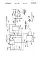
- FIG. 1is a schematic illustrating in block diagram form one embodiment of the catheter assembly associated with the present invention
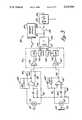
- FIG. 2is a schematic partially in block diagram form of a power conversion circuit associated with an embodiment of the present invention
- FIG. 3is a schematic partially in block diagram form illustrating the detection, demodulation and ratiometric circuits associated with a preferred form of the present invention.
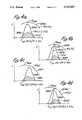
- FIGS. 4a-4ncomprise a matrix of optical spectrum graphs illustrating changes in an output signal associated with an embodiment of the present invention, with variations of pressure and temperature;
- FIG. 4ais a plot of the all-pass spectra at a constant temperature and a pressure P1;
- FIG. 4bis a plot of the long-pass spectra at a constant temperature and a pressure P1;
- FIG. 4cis a plot of the all-pass spectra at a constant temperature and a pressure P2;
- FIG. 4dis a plot of the long-pass spectra at a constant temperature and a pressure P2;
- FIG. 4eis a plot of the all-pass spectra at a constant temperature and a pressure P3;
- FIG. 4fis a plot of the long-pass spectra at a constant temperature and a pressure P3;
- FIG. 4gis a plot of the signal A and the signal B with varying pressures
- FIG. 4iis a plot of the quotient A/B with varying pressures
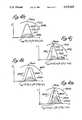
- FIG. 4his a plot of the all-pass spectra at a constant pressure and a temperature T1;
- FIG. 4jis a plot of the long-pass spectra at a constant pressure and a temperature T1;
- FIG. 4kis a plot of the all-pass spectra at a constant pressure and a temperature T2;
- FIG. 4mis a plot of the long-pass spectra at a constant pressure and a temperature T2 which affects only an LED associated with the present invention
- FIG. 4nis a plot of the long-pass spectra at a constant pressure and a temperature T2 which affects both the LED and a filter associated with the present invention
- FIG. 5is a schematic diagram of an output circuit associated with a preferred embodiment of the present invention.
- FIG. 1A monitor is illustrated in FIG. 1 and designated generally by the reference numeral 10.
- This monitoris typical of many such devices which are designed to operate with catheters (not shown) which sense pressure in body cavities using a Wheatstone bridge strain gauge.
- cathetersnot shown
- Wheatstone bridge strain gaugeWith the advent of optical pressures sensors and fiber optic technology, it is now possible to produce optical pressure catheters which operate upon the principles of optical spectral modulation.
- One such device which incorporates a Fabry-Perot interferometer in a reflective sensoris disclosed by applicant in his copending application Ser. No. 419,938, filed on Oct. 11, 1989 and entitled INTEGRAL INTRACRANIAL PRESSURE MONITOR AND DRAINAGE CATHETER ASSEMBLY. All aspects of the disclosure in that application are incorporated herein by reference.
- These optical pressure catheters and sensorsprovide a much higher degree of accuracy than the strain gauge sensors of the prior art.
- eachproviding an excitation voltage to its associated catheter, and each adapted to receive from the catheter output signals formatted in accordance with an industry standard.
- This standardbasically requires that the signal input to the monitor be proportional to the excitation voltage with each five microvolts per volt of excitation representing a pressure equal to one millimeter of mercury.
- This standardcan be better understood with reference to Table I which provides other examples of excitation voltage, input signal and resulting pressure.
- the monitorssuch as the monitor 10 are adapted to receive a similar input signal, they vary greatly in their provision of an excitation voltage.
- Many of the monitorssuch as those manufactured by Hewlett-Packard, provide an excitation voltage in the form of AC signal such as that illustrated at 12 in FIG. 1.
- This AC signal 12may have a voltage of 3.7 V rms at 2.4 kHz, for example.
- Other monitorssuch as those manufactured by Siemans, provide an excitation voltage in the form of a DC format signal as shown by the reference numeral 15.
- This signal 15may have a voltage of 2.5 volts DC.
- the monitors manufactured by Tektronixprovide an excitation voltage in a pulse format (illustrated at reference numeral 18), where each of the pulses has an amplitude of 7 volts and a duration of 20 milliseconds.
- a catheter and sensor configured to receive their only power from these random monitors, such as the monitor 10must be adapted to receive that power in any one or a combination of these formats represented by the AC signal 12, the DC signal 15 and/or the pulse signal 18.
- the signal returned to the monitormust be proportional to the instantaneous value of the excitation voltage.
- the catheter of the present inventionis shown generally at 20 in FIG. 1.
- an optical pressure sensor 22is provided which receives an input optical signal along a fiber optic conductor 24 and provides a return optical signal representative of pressure along fiber optic conductors 26 and 28.
- the fiber optic conductors 24, 26 and 28may be a single conductor as illustrated in FIG. 1.
- An electronic circuit disposed between the catheter 20 and the monitor 10is adapted to generate an optical signal from the excitation voltage of the monitor 10 and to detect the return optical signal from the catheter 20 in a format which is compatible with the monitor 10. In this manner, the fiber optic pressure catheter 20 can be connected solely to the monitor 10 without any extraneous electrical power requirement or signal input.
- the catheter 20 and associated electronicsare connected directly to the monitor 10, for example at a connector 30, to receive the excitation voltage from the monitor 10 and to supply the output pressure signal to the monitor 10.
- the excitation voltageis received along a conductor 33 and introduced to a power converter 36 as discussed in greater detail with reference to FIG. 2.
- This power converter 36is adapted to receive the excitation voltage in any of the formats shown at 12, 15, 18, or a combination thereof, to provide a supply of power at plus 5 volts DC and at minus 5 volts DC. These voltages, which are provided regardless of the format or the magnitude of the excitation voltage, are made available throughout the system on conductors 41 and 43 to power the electronic circuits discussed below.
- Timing network 44which provides a timing signal that coordinates the electronic circuits throughout the system.
- the network 39provides clock pulses at a frequency of 500 KHz.
- One such circuitis a pulse modulation circuit 39 which supplies power to the catheter 20 and associated electronics in a pulse format.
- a pulse formatprovides power only for the duration of each pulse, and therefore significantly reduces the power requirements of the system. This is particularly desirable in view of the very limited power being supplied by the typical monitor 10 in its excitation voltage.
- the pulse modulation circuit 39provides power in a pulse format with the pulse having an amplitude of 40 mA and a duty cycle of 1.6%. This power is introduced to an output LED 45 across conductors 47 and 49.
- the LED 45responds to the pulsed power from the circuit 39 by producing a pulsed optical signal illustrated by an arrow 52.
- This signal 52is introduced into the fiber optic conductor 24 of the catheter 20.
- the optical signal 52interrogates the sensor 22 which provides a return optical signal on the fiber optic conductors 26 and 28. This operation of the catheter and the sensor 22 is discussed in greater detail in applicant's copending application U.S. Ser. No. 419,938.
- a detection circuitshown generally at 55, receives this optical signal, detects it for the pressure information, and places it in a format suitable for introduction to the monitor 10.
- the detection circuit 55 of this embodimentincludes two legs 58 and 60 which are configured to receive, detect and integrate over time, the pulsed optical signal.
- leg 58the optical signal is received directly from the sensor 22 along the fiber optic conductor 28.
- leg 60the optical signal is received from the sensor 22 along the fiber optic conductor 26 but is directed through an optical filter 63 before introduction to the detection circuit 55.
- the filter 63is chosen with properties which are keyed to those of the LED 45 i n order to compensate for undesirable temperature characteristics in the return signal.
- This return signal, corrected by the filter 63,is referred to as the long-pass signal and is illustrated by an arrow 65.
- the unfiltered signal from the conductor 28is referred to as the all-pass signal and is illustrated by an arrow 67.
- These optical signals 65 and 67are directed onto respective photo diodes 69 and 72 in the detection circuit 55.
- the electrical signal from the photo diode 69is introduced across conductors 75 and 78 to a transimpedance amplifier 80.
- the signal from the photo diode 72is introduced across conductors 82 and 84 to a transimpedance amplifier 86.
- These amplifiers 80 and 86transform the current received across their respective conductor pairs 75, 78 and 82, 84 into voltages which are output onto respective conductors 88 and 90.
- the voltages on these conductors 88 and 90are received by a demodulation circuit 93 to a ratiometric converter 109 along respective conductors 112 and 115.
- the ratiometric converter 109ratios the respective signals on conductor 112 and 115 to automatically compensate for the undesirable temperature characteristics in the return signal.
- the resulting signalis appropriately scaled so that zero pressure on the sensor 22 results in a signal which is displayed as zero pressure on the monitor 10.
- This signalis introduced on a conductor 118 to an output circuit 120 which provides for further modification to the zero adjustment. This insures that the final output signal on a pair of conductors 122 and 124 signifies zero voltage at zero pressure. This output signal is introduced through the connector 30 to the monitor 10 for appropriate display.
- the importance and function of the power converter 36can be more easily understood with reference to FIG. 2.
- the converter 36receives the excitation voltage from the monitor 10 on conductor 33 previously discussed. This voltage is input into a pair of diodes 125, 127, and also to a voltage doubler circuit shown generally at 129.
- the doubler 129also includes a pair of diodes 130, 132 and a pair of capacitors 135 and 138 connected in the traditional manner as illustrated in FIG. 2. If the excitation voltage is in a DC or pulse format as illustrated at 15 and 18 respectively in FIG. 1, that voltage will pass through the diodes 125 and 127 onto a conductor 140.
- the diodes 125, 127, 132 and 135are of the Schottky type chosen to minimize voltage drop and power loss.
- the voltage doubler 129rectifies and filters that voltage to a DC format, and the resulting signal is introduced onto the conductor 140.
- An inductor 142receives the power supply on conductor 140 which functions to boost the voltage from the introductory circuit. As current through the inductor 142 is reduced, for example at the trailing edge of a pulse, this inductor 142 tends to maintain that current by increasing the voltage.
- the resultant signalis introduced into a boost converter 144 to further enhance the magnitude of the power supply.
- the boost converter 144comprises a chip 146, such as Maxim model no. MAX631ACPA, which contains an internal bypass diode (not shown).
- an additional diode 148is paralleled to reduce power loss.
- the converter 144receive an input voltage of at least 2 volts DC in order for it to function properly. Acknowledging appropriate resistance drops for the diodes 125, 127, 130 and 132, it is desirable that the input excitation voltage V ex from the monitor 10 be at least 2.3 volts.
- the boost converter 144It is the function of the boost converter 144 to raise the input voltage, such as 2 volts DC, to an amplitude of about 6 volts DC. If the voltage input to the converter 144 is greater than 6 volts DC, it will bypass the amplification provided by the chip 146 and pass directly through the internal diode (not shown) and the diode 148. The resultant signal of at least 6 volts DC is output on a conductor 150 which is appropriately filtered by an output capacitor 153. A pair of resistors 156 and 159 provide a feedback control circuit for setting the output of chip 146.
- the signal on conductor 150 iintroduced to a regulator shown generally at 161. It is the function of regulator 161 to receive the voltage from converter 144, which has a magnitude of at least 6 volts DC, and to regulate that voltage to a positive 5 volts DC.
- the regulator 161includes a chip 163 which in a preferred embodiment is a Maxim model no. of ICL7663CPA.
- the output chip 163is directed through a current limiting resistor 165.
- Resistors 167 and 169form part of a feedback control circuit for chip 163 which provides its output on conductor 41, previously discussed with reference to FIG. 1.
- the plus 5 volt DC signal on conductor 41is introduced to a charge pump inverter shown generally at 172.
- This inverter 172may include a chip 175 such as Maxim ICL7660CPA.
- a charge capacitor 177 associated with the inverter 172flips the input positive voltage so that a voltage with a same magnitude but a reverse polarity is introduced on the conductor 43. In this manner, the charge pump inverter 172 provides the minus 5 volt DC signal which is available throughout the monitoring system.
- the pulse modulation circuit 39In response to these supply voltages on the conductors 41 and 43, the pulse modulation circuit 39 produces a series of pulses which are output on conductor 47 to pulse LED 45.
- the optical signal represented by arrow 52is then introduced to catheter 20 as a pulsating light signal.
- the electrical signal on conductor 47has an amplitude of 40 mA and a pulse duty cycle of 1.5%.
- the electronics associated with the return signalare illustrated in greater detail in FIG. 3.
- the all-pass photo signal 67is directed onto the photo diode 72 and the long-pass signal 65 is directed onto the photo diode 69.
- the electrical signal from the diode 72which is presented across conductors 82 and 84 is introduced to a preamp 178.
- a conductor 82is biased through a resistor 181 in order to minimize preamp offsets.
- the output of preamp 78 idirected onto conductor 90, but a feedback circuit including the parallel combination of a capacitor 183 and a resistor 185 carries the output signal back to the conductor 84.
- the resistor 185which provides the primary characteristics associated with transimpedance amplifier 86. More specifically, the output on conductor 90 is a negative voltage equal to the value of the input current multiplied by the impedance of resistor 185.
- the preamp 178 in a preferred embodimentis a model LT1078ACN8 with supply voltages appropriately filtered by a pair of decoupling capacitors 187 and 189.
- the output on conductor 88is a negative voltage equal to the magnitude of the input current on conductor 78 multiplied by the impedance of resistor 185'.
- an integrator 192provides an output proportional to the voltage on conductor 90 multiplied by the LED pulse time. This output of the integrator 192 is introduced to a switch circuit 195 which is synchronized to the timer in pulse modulation circuit 39. The resulting signal is processed in a sample and hold circuit 198 and introduced onto conductor 115. In the following discussion this signal is referred to as the all-pass signal A.
- these circuits 192, 195 & 198are duplicated and designated with the same reference numerals primed, 192', 195' & 198 '.
- the signal from the sample-and-hold circuit 198' in the leg 60'is introduced onto conductor 112. In the following discussion, this signal is referred to as the long-pass signal B.
- FIG. 4is subdivided into FIGS. 4a-4n.
- FIGS. 4a-4nillustrates various spectral frequencies with variations in temperature and pressure.
- the graphs of FIGS. 4a-4gillustrate spectral shifts under conditions of constant temperature and varying pressure.
- the LED spectrum 202ais illustrated to have its peak generally centered on the peak or maximum value R max of the sensor spectrum 204a.
- the signal which actually occurs on the conductor 84is the wavelength integral of the product of these two spectra 202a and 204a.
- the combination spectrumis designated 208a in FIG. 4a and is derived by multiplying the instantaneous values of the spectra 202b and 204b at each of the wavelengths in the spectrum.
- the photo detector 72outputs a current which is proportional to the area under the combination spectrum 208a.
- a signalis present on conductor 115 which is representative of the value of the area under the combination spectrum 208a averaged over the LED pulse on time interval. This signal is updated during each LED pulse. At pressure P1 this area is given by the formula illustrated in FIG. 4a.
- these same spectra 202b and 204brepresent the signals in the long-pass leg 60 and also appear with their peaks generally aligned for the pressure P1.
- the long-pass leg 60differs from the all-pass leg 58 solely by the provision of the filter 63 which is disposed between the sensor 22 and the LED 69.
- This filter 63adds to the analysis its spectrum which is designated by the reference 206b in FIG. 4b.
- these spectra 202b, 204b and 206bmultiply to provide the combination spectrum 208b on conductor 78.
- the combination spectrum 208bis derived by multiplying the instantaneous values of the spectra 202b, 204b as well as the spectrum 206b at each of the wavelengths in the spectrum.
- the signal on conductor 112represents the area beneath the combination spectrum 208b averaged over the LED pulse on-time interval, and is characterized by the formula illustrated in FIG. 4b.
- FIGS. 4c and 4dA change from pressure P1 to a greater pressure P2 is illustrated in FIGS. 4c and 4d for the respective all-pass and long-pass legs 58 and 60. Since a change in pressure does not affect the intensity of the LED 45, the LED spectrum 202c remains the same. It is the sensor 22 which experiences the pressure change and responds with a dramatic shift to the left of the sensor spectrum 204c. Of course the product of these two signals must also change, so the combination spectrum 208c now appears less symmetrical than the spectrum 208a with its peak also shifting to the left. More importantly, the area beneath this combination spectrum 208c is significantly reduced. At the pressure P2 this area for the all-pass leg 58 is represented by the formula illustrated in FIG. 4c.
- FIG. 4dillustrates the same shift of the LED spectrum 204d, but the filter spectrum 206d does not shift with the change to pressure P2.
- a product of the three spectrum 202d, 204d and 206dresults in the combination spectrum 208d which is shifted slightly to the left from its position in FIG. 4b.
- the signal on conductor 112varies with the area beneath this combination spectrum 208d and is represented by the formula illustrated in FIG. 4d.
- the sensor spectrum 204will shift even further to the left as illustrated at 204e in FIG. 4e. Since this spectrum 204e has a dramatic change in shape along its right side, its instantaneous wavelength values dramatically affect the shape of the product or combination spectrum 208e. Of course, the area beneath the combination spectrum 208e also changes dramatically and is as represented by the formula illustrated in FIG. 4e.
- FIGS. 4a, 4c and 4eillustrates that a change in pressure from P1 to P3 results in a slight change in the area beneath the combination spectrum 208 in the all-pass leg 58.
- This changecan be plotted against pressure to illustrate that the change is generally sinusoidal as shown by a signal 209 in FIG. 4g. This is actually the all-pass signal B which occurs on conductor 115.
- FIGS. 4b, 4d and 4fwhich relate to the long-pass leg 60, show a similar change in the area beneath the curve 208 even when the filter spectrum 206 is added to the leg.
- the changes in the area beneath the combination spectrum 208can be plotted against pressure to show a generally sinusoidal curve designated by the reference numeral 211 in FIG. 4g. This is actually the long-pass signal A which occurs on conductor 112.
- a comparison of the A signal and B signalindicates that they are generally similar in shape but tend to be slightly out of phase. This results from the presence of the filter 63 in the long-pass leg 60 which adds the spectrum 206 to the analysis. Since the filter spectrum 206 occurs slightly to the right of the maximum value for the LED spectrum 202, the maximum area for the combination spectrum 208 tends to occur at a slightly lower pressure than it does in the all-pass leg 58. Although these changes in magnitude and phase differ only slightly with pressure, a dramatic difference occurs when the signal A is divided by the signal B.
- This twin spectral band ratiometric techniquehas a number of significant advantages which are shown in a plot of the quotient A/B with varying pressures. This plot is illustrated in FIG. 4g'. It will be first noted that, the A/B ratio signal is significantly more linear in a portion of its range than either the A or B signals. This allows the system to use the A/B ratio signal directly without any additional linearization, provided the applied pressures are restricted to this range. Second, since variations in LED intensity--which may be due to aging, input power variations, or optical coupling efficiency--generally affect all wavelengths, equally, it follows that both the A and B signals are affected equally. Thus, the ratiometric signal A/B is substantially independent of the optical power output of the LED. Third, optical power losses due to imperfections in optical connections and bending of the optical fibers, generally affect all wavelengths equally. Providing the ratiometric signal A/B tends to neutralize these variations leaving the signal generally unaffected by these optical power losses.
- FIGS. 4a-4ghas illustrated how a slight change in pressure at the sensor 22 can result in a significant change in the resulting quotient A/B. It will now be shown with reference to FIGS. 4h to 4n that changes in temperature can produce an undesirable effect on the monitoring signals.
- FIG. 4hillustrates that at a given temperature T1 and constant pressure P1, the LED spectrum 202h and sensor spectrum 204h may be generally aligned as previously discussed with reference to FIG. 4a. Multiplying these spectra 202h and 204h in the all-pass leg 58 produces the combination spectrum 208h which has an area represented by the formula illustrated in FIG. 4h.
- the combination spectrum 208his similar in size and shape to the spectrum 208a discussed with reference to FIG. 4a.
- FIG. 4jillustrates that at the temperature T1 the long-pass leg 60 which includes the filter 63 will produce a combination spectrum 208j.
- This spectrum 208jis similar in size and shape to that illustrated in FIG. 4b at the pressure P1.
- FIG. 4millustrates that a change in temperature from T1 to T2 shifts the LED spectrum 202m to the right.
- the characteristics of the LED 45result in a change from the dotted line 202m prime to the solid line associated with the spectrum 202m.
- This shiftis relative to both the sensor spectrum 204m and the filter spectrum 206m which do not vary with temperature.
- the combination spectrum 208mactually increases in size. This area is represented by the formula illustrated in FIG. 4m.
- the filter 63can be chosen with characteristics which also vary with temperature. In fact, the filter 63 can be chosen so that its temperature characteristics are quite similar to those associated with the LED 45.
- the filter 63provides a shift of its spectrum 206m which varies with temperature to about the same extent as the LED spectrum 202m. In FIG. 4n these spectral shifts are illustrated with a change from the dotted line 202m' to the solid line of spectrum 202n, and from the dotted line 206m' to the solid line of spectrum 206m. Since both of the spectra 202m and 206m are shifting, the change in the area beneath the combination spectrum 208m is relatively insignificant.
- the undesirable components of the pressure signal A/Bwhich vary with temperature, can be reduced to approximately 0.5 percent of the full scale output per degree centigrade.
- the undesirable temperature componentscan be reduced by a factor of ten by choosing the filter 63 with appropriate temperature characteristics. If these characteristics are chosen to coincide generally with the temperature characteristics of the LED 45, the only change in the pressure signal A/B will be due generally to the shape of the sensor spectrum 204m which is slightly curved rather than flat. Even these affects can be minimized by maintaining the spectrums of the LED 45 and filter 63 in the generally linear portions of the sensor spectrum 204.
- the all-pass signal Ais presented on conductor 115 and the long-pass signal B is presented on conductor 112.
- these signalsare introduced to a divider network 210 as shown in FIG. 3.
- the signal Ais divided by the signal B and a constant value is subtracted from the quotient.
- This valueis the estimate of the zero pressure ratio A o /B o , and serves to reduce the magnitude of the resultant signal to a valve that can be accommodated by the various monitors, such as the monitor 10.
- the valueis digitized to provide a 12-bit digital signal.
- This digital signalis introduced to a multiplier network 212 which multiplies the quantity [(A/B)-1] by a factor C which scales the signal. In a preferred embodiment this is accomplished through a series of digitally actuated resistive gates which produce the resultant signal [(A/B)-1](C) in analog form.
- the multiplicative factor Cis made to be proportional to the instantaneous value of the excitation voltage supplied by the monitor 10.
- the resulting analog signal [(A/B)-1](C)is both proportional to the excitation voltage supplied by the monitor 10 and also to the applied pressure as required by the monitor 10.
- the combined signal [(A/B)-1](C)can also be scaled to the industry standard of five microvolts per volt per millimeter of mercury.
- a 12-bit memory bank 214is provided. When the pressure on the sensor 22 is Known to be zero, this memory bank 214 can be switched to store the output of the divider network 210. If it becomes desirable to disconnect the catheter 20 from a monitor 10 in one location such as the operating room, it can be reconnected to a different monitor 10 in another location, such as a critical care room. Under these circumstances, the digital signal in the memory 214 can be introduced through a switch 216 to zero the new monitor.
- the analog signal on the conductor 118is introduced to the output circuit 120 which is illustrated in greater detail in FIG. 5.
- the conductor 118is connected through a resistor 218 to an operational amplifier shown generally at 221.
- the positive input to this amplifier 221is appropriately biased between the two excitation voltages by a pair of resistors 223 and 225.
- the same biasis applied to the positive input of a second operational amplifier 227.
- a potentiometer 229 placed across the two excitation voltagesprovides input through a resistor 231 to the negative terminal of the amplifier 227.
- the potentiometer 229can be adjusted to provide a gross zero adjustment for the catheter 20. This adjustment typically would be fixed by the manufacturer so that any deviations from zero could be accomplished by adjusting the monitor 10.
- the output of the operational amplifiers 221 and 227is directed through respective output resistors 233 and 236 on conductors 124 and 122.
- the final output signal presented across these conductors 122 and 124is introduced through the connector 30 to the monitor 10. With suitable zero adjustments the monitor 10 will display a zero value when the sensor 22 is disposed in a zero pressure environment.
- the optical catheter 20 and associated electronicsis operable with many types of monitors 10 regardless of the format of the monitor's excitation power and in spite of the fact that these monitors have been designed for use with strain gauge sensors.
- the signals presented by the optical catheter 20are corrected for temperature so that variations in the signal are dependent almost entirely upon variations in the pressure of the fluid surrounding the sensor 22.
Landscapes
- Health & Medical Sciences (AREA)
- Life Sciences & Earth Sciences (AREA)
- Physics & Mathematics (AREA)
- Molecular Biology (AREA)
- Animal Behavior & Ethology (AREA)
- Cardiology (AREA)
- Biophysics (AREA)
- Pathology (AREA)
- Engineering & Computer Science (AREA)
- Biomedical Technology (AREA)
- Heart & Thoracic Surgery (AREA)
- Medical Informatics (AREA)
- Veterinary Medicine (AREA)
- Surgery (AREA)
- Public Health (AREA)
- General Health & Medical Sciences (AREA)
- Hematology (AREA)
- General Physics & Mathematics (AREA)
- Neurosurgery (AREA)
- Vascular Medicine (AREA)
- Physiology (AREA)
- Measuring Fluid Pressure (AREA)
- Compression Or Coding Systems Of Tv Signals (AREA)
- Measuring And Recording Apparatus For Diagnosis (AREA)
Abstract
Description
TABLE I ______________________________________ V.sub.ex Signal Pressure ______________________________________ 5 VDC 25 μV = 1 mmHg 5 VDC 50 μV = 2 mmHg 10 VDC 50 μV = 1 mmHg 5V.sub.rms @5kHz 50 μV.sub.rms = 2 mmHg (in phase with excitation) ______________________________________
i.sub.LP (T.sub.1)≃i.sub.LP (T.sub.2) (Formula IV)
Claims (21)
Priority Applications (6)
| Application Number | Priority Date | Filing Date | Title |
|---|---|---|---|
| US07/485,349US5325865A (en) | 1990-02-26 | 1990-02-26 | Intracranial pressure monitoring system |
| PCT/US1991/000985WO1991012767A1 (en) | 1990-02-26 | 1991-02-12 | Intracranial pressure monitoring system |
| DE69118177TDE69118177T2 (en) | 1990-02-26 | 1991-02-12 | ARRANGEMENT OF BRAIN PRESSURE |
| EP91904997AEP0524188B1 (en) | 1990-02-26 | 1991-02-12 | Intracranial pressure monitoring system |
| CA002077089ACA2077089C (en) | 1990-02-26 | 1991-02-12 | Intracranial pressure monitoring system |
| JP3504719AJP3062661B2 (en) | 1990-02-26 | 1991-02-12 | Intracranial pressure measurement system |
Applications Claiming Priority (1)
| Application Number | Priority Date | Filing Date | Title |
|---|---|---|---|
| US07/485,349US5325865A (en) | 1990-02-26 | 1990-02-26 | Intracranial pressure monitoring system |
Publications (1)
| Publication Number | Publication Date |
|---|---|
| US5325865Atrue US5325865A (en) | 1994-07-05 |
Family
ID=23927810
Family Applications (1)
| Application Number | Title | Priority Date | Filing Date |
|---|---|---|---|
| US07/485,349Expired - LifetimeUS5325865A (en) | 1990-02-26 | 1990-02-26 | Intracranial pressure monitoring system |
Country Status (6)
| Country | Link |
|---|---|
| US (1) | US5325865A (en) |
| EP (1) | EP0524188B1 (en) |
| JP (1) | JP3062661B2 (en) |
| CA (1) | CA2077089C (en) |
| DE (1) | DE69118177T2 (en) |
| WO (1) | WO1991012767A1 (en) |
Cited By (56)
| Publication number | Priority date | Publication date | Assignee | Title |
|---|---|---|---|---|
| US5568815A (en)* | 1994-11-21 | 1996-10-29 | Becton Dickinson And Company | Self-powered interface circuit for use with a transducer sensor |
| US5617873A (en)* | 1994-08-25 | 1997-04-08 | The United States Of America As Represented By The Administrator, Of The National Aeronautics And Space Administration | Non-invasive method and apparatus for monitoring intracranial pressure and pressure volume index in humans |
| US5928182A (en)* | 1997-07-02 | 1999-07-27 | Johnson & Johnson Professional, Inc. | Pediatric programmable hydrocephalus valve |
| US5935084A (en)* | 1997-09-30 | 1999-08-10 | Johnson & Johnson Professional, Inc. | Inflatable pressure indicator |
| US6120457A (en)* | 1997-07-02 | 2000-09-19 | Johnson & Johnson Professional, Inc. | In vivo zeroing of catheter pressure sensor |
| US6126628A (en)* | 1997-04-22 | 2000-10-03 | Johnson & Johnson Professional, Inc. | Fluid flow limiting device |
| US6248080B1 (en) | 1997-09-03 | 2001-06-19 | Medtronic, Inc. | Intracranial monitoring and therapy delivery control device, system and method |
| US6537232B1 (en) | 1997-05-15 | 2003-03-25 | Regents Of The University Of Minnesota | Intracranial pressure monitoring device and method for use in MR-guided drug delivery |
| US20030093129A1 (en)* | 2001-10-29 | 2003-05-15 | Nicolelis Miguel A.L. | Closed loop brain machine interface |
| US20030105409A1 (en)* | 2001-11-14 | 2003-06-05 | Donoghue John Philip | Neurological signal decoding |
| US20030176905A1 (en)* | 2002-03-14 | 2003-09-18 | Nicolelis Miguel A.L. | Miniaturized high-density multichannel electrode array for long-term neuronal recordings |
| US20040015211A1 (en)* | 2002-06-04 | 2004-01-22 | Nurmikko Arto V. | Optically-connected implants and related systems and methods of use |
| US6731976B2 (en) | 1997-09-03 | 2004-05-04 | Medtronic, Inc. | Device and method to measure and communicate body parameters |
| US20040249302A1 (en)* | 2003-06-09 | 2004-12-09 | Cyberkinetics, Inc. | Methods and systems for processing of brain signals |
| US20050113744A1 (en)* | 2003-11-21 | 2005-05-26 | Cyberkinetics, Inc. | Agent delivery systems and related methods under control of biological electrical signals |
| US20050143589A1 (en)* | 2003-11-09 | 2005-06-30 | Donoghue John P. | Calibration systems and methods for neural interface devices |
| US20050171452A1 (en)* | 2004-02-03 | 2005-08-04 | Samuel Neff | Cerebral spinal fluid shunt evaluation system |
| US20050203366A1 (en)* | 2004-03-12 | 2005-09-15 | Donoghue John P. | Neurological event monitoring and therapy systems and related methods |
| US20050267597A1 (en)* | 2003-11-25 | 2005-12-01 | Flaherty J Christopher | Neural interface system with embedded id |
| US20050283203A1 (en)* | 2003-12-29 | 2005-12-22 | Flaherty J C | Transcutaneous implant |
| US20060049957A1 (en)* | 2004-08-13 | 2006-03-09 | Surgenor Timothy R | Biological interface systems with controlled device selector and related methods |
| US20060149338A1 (en)* | 2005-01-06 | 2006-07-06 | Flaherty J C | Neurally controlled patient ambulation system |
| US20060167371A1 (en)* | 2005-01-10 | 2006-07-27 | Flaherty J Christopher | Biological interface system with patient training apparatus |
| US20060167530A1 (en)* | 2005-01-06 | 2006-07-27 | Flaherty J C | Patient training routine for biological interface system |
| US20060173259A1 (en)* | 2004-10-04 | 2006-08-03 | Flaherty J C | Biological interface system |
| US20060189900A1 (en)* | 2005-01-18 | 2006-08-24 | Flaherty J C | Biological interface system with automated configuration |
| US20060189899A1 (en)* | 2005-01-10 | 2006-08-24 | Flaherty J Christopher | Joint movement apparatus |
| US20060241356A1 (en)* | 2005-01-06 | 2006-10-26 | Flaherty J C | Biological interface system with gated control signal |
| US7212851B2 (en) | 2002-10-24 | 2007-05-01 | Brown University Research Foundation | Microstructured arrays for cortex interaction and related methods of manufacture and use |
| US20070106143A1 (en)* | 2005-11-08 | 2007-05-10 | Flaherty J C | Electrode arrays and related methods |
| US20070156126A1 (en)* | 2005-12-29 | 2007-07-05 | Flaherty J C | Medical device insertion system and related methods |
| WO2007078463A1 (en) | 2005-12-22 | 2007-07-12 | The Trustees Of Columbia University In The City Of New York | Systems and methods for intravascular cooling |
| US7317409B2 (en) | 2002-01-30 | 2008-01-08 | Tensys Medical, Inc. | Apparatus and method for interfacing time-variant signals |
| US20080045883A1 (en)* | 2006-08-17 | 2008-02-21 | Milan Radojicic | Devices and methods for monitoring and delivering therapeutics to the spinal cord |
| US20080214951A1 (en)* | 2004-02-03 | 2008-09-04 | Neuro Diagnostic Devices, Inc. | Cerebrospinal Fluid Evaluation Systems |
| US20090112215A1 (en)* | 2007-10-29 | 2009-04-30 | Sherman Jason T | Opto-electric indicators for orthopaedic instruments |
| US20090227851A1 (en)* | 2006-08-17 | 2009-09-10 | Milan Radojicic | System and method for monitoring and delivering therapeutics to the spinal cord |
| US20100023021A1 (en)* | 2005-12-27 | 2010-01-28 | Flaherty J Christopher | Biological Interface and Insertion |
| US20110092840A1 (en)* | 2009-09-23 | 2011-04-21 | Feather Sensors Llc | Intelligent air flow sensors |
| US7946994B2 (en) | 2004-10-07 | 2011-05-24 | Tensys Medical, Inc. | Compact apparatus and methods for non-invasively measuring hemodynamic parameters |
| US20110131588A1 (en)* | 2009-12-01 | 2011-06-02 | International Business Machines Corporation | Software architecture that can sense and respond to contextual and state information |
| US20120116233A1 (en)* | 2010-11-04 | 2012-05-10 | Robert Weber Mah | Sensor system |
| US8313442B2 (en) | 2009-10-21 | 2012-11-20 | Codman & Shurtleff, Inc. | Cerebral compliance monitoring |
| US8926520B2 (en)* | 2012-07-20 | 2015-01-06 | Endophys Holdings, Llc | Transducer interface system and method |
| WO2015010064A1 (en)* | 2013-07-18 | 2015-01-22 | Board Of Regents Of The University Of Texas System | Blood pressure analysis system and method |
| CN104905781A (en)* | 2015-02-13 | 2015-09-16 | 林昌军 | Encephalic physiological parameter collecting device and application |
| US9265577B2 (en) | 2007-05-18 | 2016-02-23 | The Johns Hopkins University | Methods and systems for providing planning and dispensation of research and/or treatment for brain disease |
| US9463276B2 (en) | 2008-08-16 | 2016-10-11 | Milan Radojicic | Systems and methods for a computational medical device in dynamic body systems |
| WO2016183123A1 (en)* | 2015-05-11 | 2016-11-17 | Alcyone Lifesciences, Inc. | Drug delivery systems and methods |
| US9510786B2 (en) | 2011-06-22 | 2016-12-06 | Biosense Webster (Israel) Ltd. | Optical pressure measurement |
| US10039491B2 (en) | 2014-06-30 | 2018-08-07 | Verily Life Sciences Llc | Methods for reducing noise in optical biological sensors |
| US10285598B2 (en) | 2006-05-13 | 2019-05-14 | United States Gtm Medical Devices | Continuous positioning apparatus and methods |
| US10478555B2 (en) | 2006-08-17 | 2019-11-19 | Milan Radojicic | Systems and methods for lumbar cerebrospinal fluid access and treatment |
| US10653442B2 (en) | 2016-12-21 | 2020-05-19 | Alcyone Lifesciences, Inc. | Drug delivery systems and methods |
| US10952675B2 (en) | 2007-10-12 | 2021-03-23 | Shangyi Medical Technology (Hangzhou) Co., Ltd | Apparatus and methods for non-invasively measuring a patient's arterial blood pressure |
| US12310704B2 (en) | 2019-09-13 | 2025-05-27 | Endophys Holdings, Llc | Blood pressure monitoring with zero function system and method |
Families Citing this family (4)
| Publication number | Priority date | Publication date | Assignee | Title |
|---|---|---|---|---|
| US5275053A (en)* | 1991-08-21 | 1994-01-04 | Fiberoptic Sensor Technologies, Inc. | Fiber optic pressure sensor systems |
| US5919144A (en)* | 1997-05-06 | 1999-07-06 | Active Signal Technologies, Inc. | Apparatus and method for measurement of intracranial pressure with lower frequencies of acoustic signal |
| GB2374925A (en)* | 2001-04-24 | 2002-10-30 | Anant Sharma | Pressure detectors |
| US20240146252A1 (en)* | 2022-10-31 | 2024-05-02 | Cisco Technology, Inc. | Baseline wander differential tia with resistive feedforward ac coupling path |
Citations (10)
| Publication number | Priority date | Publication date | Assignee | Title |
|---|---|---|---|---|
| US3215135A (en)* | 1963-02-04 | 1965-11-02 | Ernst K Franke | Miniature pressure gauge for the measurement of intravascular blood pressure |
| US4487206A (en)* | 1982-10-13 | 1984-12-11 | Honeywell Inc. | Fiber optic pressure sensor with temperature compensation and reference |
| US4678904A (en)* | 1984-07-06 | 1987-07-07 | Technology Dynamics, Inc. | Optical measuring device using a spectral modulation sensor having an optically resonant structure |
| US4711246A (en)* | 1986-09-02 | 1987-12-08 | Fiberoptic Sensor Technologies, Inc. | Fiber optic coupled pressure transducer using single fiber and method of fabrication |
| US4787396A (en)* | 1987-06-18 | 1988-11-29 | Fiberoptic Sensor Technologies, Inc. | Fiberoptic pressure transducer |
| US4817022A (en)* | 1986-07-30 | 1989-03-28 | Barber-Colman Company | Method and apparatus for automatic offset compensation in parameter-sensing transducer systems |
| US4883062A (en)* | 1988-04-25 | 1989-11-28 | Medex, Inc. | Temperture and pressure monitors utilizing interference filters |
| US4897542A (en)* | 1987-03-31 | 1990-01-30 | Plessey Overseas Limited | Optical pressure sensor |
| US4924870A (en)* | 1989-01-13 | 1990-05-15 | Fiberoptic Sensor Technologies, Inc. | Fiber optic sensors |
| US4933545A (en)* | 1985-12-30 | 1990-06-12 | Metricor, Inc. | Optical pressure-sensing system using optical resonator cavity |
- 1990
- 1990-02-26USUS07/485,349patent/US5325865A/ennot_activeExpired - Lifetime
- 1991
- 1991-02-12WOPCT/US1991/000985patent/WO1991012767A1/enactiveIP Right Grant
- 1991-02-12DEDE69118177Tpatent/DE69118177T2/ennot_activeExpired - Lifetime
- 1991-02-12JPJP3504719Apatent/JP3062661B2/ennot_activeExpired - Lifetime
- 1991-02-12EPEP91904997Apatent/EP0524188B1/ennot_activeExpired - Lifetime
- 1991-02-12CACA002077089Apatent/CA2077089C/ennot_activeExpired - Lifetime
Patent Citations (10)
| Publication number | Priority date | Publication date | Assignee | Title |
|---|---|---|---|---|
| US3215135A (en)* | 1963-02-04 | 1965-11-02 | Ernst K Franke | Miniature pressure gauge for the measurement of intravascular blood pressure |
| US4487206A (en)* | 1982-10-13 | 1984-12-11 | Honeywell Inc. | Fiber optic pressure sensor with temperature compensation and reference |
| US4678904A (en)* | 1984-07-06 | 1987-07-07 | Technology Dynamics, Inc. | Optical measuring device using a spectral modulation sensor having an optically resonant structure |
| US4933545A (en)* | 1985-12-30 | 1990-06-12 | Metricor, Inc. | Optical pressure-sensing system using optical resonator cavity |
| US4817022A (en)* | 1986-07-30 | 1989-03-28 | Barber-Colman Company | Method and apparatus for automatic offset compensation in parameter-sensing transducer systems |
| US4711246A (en)* | 1986-09-02 | 1987-12-08 | Fiberoptic Sensor Technologies, Inc. | Fiber optic coupled pressure transducer using single fiber and method of fabrication |
| US4897542A (en)* | 1987-03-31 | 1990-01-30 | Plessey Overseas Limited | Optical pressure sensor |
| US4787396A (en)* | 1987-06-18 | 1988-11-29 | Fiberoptic Sensor Technologies, Inc. | Fiberoptic pressure transducer |
| US4883062A (en)* | 1988-04-25 | 1989-11-28 | Medex, Inc. | Temperture and pressure monitors utilizing interference filters |
| US4924870A (en)* | 1989-01-13 | 1990-05-15 | Fiberoptic Sensor Technologies, Inc. | Fiber optic sensors |
Cited By (96)
| Publication number | Priority date | Publication date | Assignee | Title |
|---|---|---|---|---|
| US5617873A (en)* | 1994-08-25 | 1997-04-08 | The United States Of America As Represented By The Administrator, Of The National Aeronautics And Space Administration | Non-invasive method and apparatus for monitoring intracranial pressure and pressure volume index in humans |
| US5568815A (en)* | 1994-11-21 | 1996-10-29 | Becton Dickinson And Company | Self-powered interface circuit for use with a transducer sensor |
| EP0712603A3 (en)* | 1994-11-21 | 2006-06-07 | Becton, Dickinson and Company | A self-powered interface circuit for use with a transducer sensor |
| US6126628A (en)* | 1997-04-22 | 2000-10-03 | Johnson & Johnson Professional, Inc. | Fluid flow limiting device |
| US6537232B1 (en) | 1997-05-15 | 2003-03-25 | Regents Of The University Of Minnesota | Intracranial pressure monitoring device and method for use in MR-guided drug delivery |
| US5928182A (en)* | 1997-07-02 | 1999-07-27 | Johnson & Johnson Professional, Inc. | Pediatric programmable hydrocephalus valve |
| US6120457A (en)* | 1997-07-02 | 2000-09-19 | Johnson & Johnson Professional, Inc. | In vivo zeroing of catheter pressure sensor |
| US6731976B2 (en) | 1997-09-03 | 2004-05-04 | Medtronic, Inc. | Device and method to measure and communicate body parameters |
| US6248080B1 (en) | 1997-09-03 | 2001-06-19 | Medtronic, Inc. | Intracranial monitoring and therapy delivery control device, system and method |
| US5935084A (en)* | 1997-09-30 | 1999-08-10 | Johnson & Johnson Professional, Inc. | Inflatable pressure indicator |
| US20030093129A1 (en)* | 2001-10-29 | 2003-05-15 | Nicolelis Miguel A.L. | Closed loop brain machine interface |
| US7209788B2 (en) | 2001-10-29 | 2007-04-24 | Duke University | Closed loop brain machine interface |
| US20030105409A1 (en)* | 2001-11-14 | 2003-06-05 | Donoghue John Philip | Neurological signal decoding |
| US7392079B2 (en) | 2001-11-14 | 2008-06-24 | Brown University Research Foundation | Neurological signal decoding |
| US20080109199A1 (en)* | 2002-01-30 | 2008-05-08 | Conero Ronald S | Apparatus and method for interfacing time-variant signals |
| US7317409B2 (en) | 2002-01-30 | 2008-01-08 | Tensys Medical, Inc. | Apparatus and method for interfacing time-variant signals |
| US8818731B2 (en) | 2002-01-30 | 2014-08-26 | Tensys Medical, Inc. | Apparatus and method for interfacing time-variant signals |
| US10335081B2 (en) | 2002-01-30 | 2019-07-02 | United States Gtm Medical Devices | Apparatus and method for interfacing time-variant signals |
| US6993392B2 (en) | 2002-03-14 | 2006-01-31 | Duke University | Miniaturized high-density multichannel electrode array for long-term neuronal recordings |
| US20060206161A1 (en)* | 2002-03-14 | 2006-09-14 | Duke University | Miniaturized high-density multichannel electrode array for long-term neuronal recordings |
| US7983756B2 (en) | 2002-03-14 | 2011-07-19 | Duke University | Miniaturized high-density multichannel electrode array for long-term neuronal recordings |
| US20030176905A1 (en)* | 2002-03-14 | 2003-09-18 | Nicolelis Miguel A.L. | Miniaturized high-density multichannel electrode array for long-term neuronal recordings |
| US7280870B2 (en) | 2002-06-04 | 2007-10-09 | Brown University Research Foundation | Optically-connected implants and related systems and methods of use |
| US20040015211A1 (en)* | 2002-06-04 | 2004-01-22 | Nurmikko Arto V. | Optically-connected implants and related systems and methods of use |
| US20070169333A1 (en)* | 2002-10-24 | 2007-07-26 | Donoghue John P | Microstructured arrays for cortex interaction and related methods of manufacture and use |
| US7212851B2 (en) | 2002-10-24 | 2007-05-01 | Brown University Research Foundation | Microstructured arrays for cortex interaction and related methods of manufacture and use |
| US20040249302A1 (en)* | 2003-06-09 | 2004-12-09 | Cyberkinetics, Inc. | Methods and systems for processing of brain signals |
| US20050143589A1 (en)* | 2003-11-09 | 2005-06-30 | Donoghue John P. | Calibration systems and methods for neural interface devices |
| US20050113744A1 (en)* | 2003-11-21 | 2005-05-26 | Cyberkinetics, Inc. | Agent delivery systems and related methods under control of biological electrical signals |
| US20050267597A1 (en)* | 2003-11-25 | 2005-12-01 | Flaherty J Christopher | Neural interface system with embedded id |
| US7751877B2 (en) | 2003-11-25 | 2010-07-06 | Braingate Co., Llc | Neural interface system with embedded id |
| US20050273890A1 (en)* | 2003-11-25 | 2005-12-08 | Flaherty J C | Neural interface system and method for neural control of multiple devices |
| US7647097B2 (en) | 2003-12-29 | 2010-01-12 | Braingate Co., Llc | Transcutaneous implant |
| US20050283203A1 (en)* | 2003-12-29 | 2005-12-22 | Flaherty J C | Transcutaneous implant |
| US20080214951A1 (en)* | 2004-02-03 | 2008-09-04 | Neuro Diagnostic Devices, Inc. | Cerebrospinal Fluid Evaluation Systems |
| US7520862B2 (en) | 2004-02-03 | 2009-04-21 | Neuro Diagnostic Devices, Inc. | Cerebral spinal fluid shunt evaluation system |
| US20050171452A1 (en)* | 2004-02-03 | 2005-08-04 | Samuel Neff | Cerebral spinal fluid shunt evaluation system |
| US20050203366A1 (en)* | 2004-03-12 | 2005-09-15 | Donoghue John P. | Neurological event monitoring and therapy systems and related methods |
| US20060058627A1 (en)* | 2004-08-13 | 2006-03-16 | Flaherty J C | Biological interface systems with wireless connection and related methods |
| US20060049957A1 (en)* | 2004-08-13 | 2006-03-09 | Surgenor Timothy R | Biological interface systems with controlled device selector and related methods |
| US8560041B2 (en) | 2004-10-04 | 2013-10-15 | Braingate Co., Llc | Biological interface system |
| US20060173259A1 (en)* | 2004-10-04 | 2006-08-03 | Flaherty J C | Biological interface system |
| US9247886B2 (en) | 2004-10-07 | 2016-02-02 | Tensys Medical, Inc. | Compact apparatus and methods for non-invasively measuring hemodynamic parameters |
| US7946994B2 (en) | 2004-10-07 | 2011-05-24 | Tensys Medical, Inc. | Compact apparatus and methods for non-invasively measuring hemodynamic parameters |
| US20060253166A1 (en)* | 2005-01-06 | 2006-11-09 | Flaherty J C | Patient training routine for biological interface system |
| US20060206167A1 (en)* | 2005-01-06 | 2006-09-14 | Flaherty J C | Multi-device patient ambulation system |
| US20060241356A1 (en)* | 2005-01-06 | 2006-10-26 | Flaherty J C | Biological interface system with gated control signal |
| US20070032738A1 (en)* | 2005-01-06 | 2007-02-08 | Flaherty J C | Adaptive patient training routine for biological interface system |
| US8095209B2 (en) | 2005-01-06 | 2012-01-10 | Braingate Co., Llc | Biological interface system with gated control signal |
| US7991461B2 (en) | 2005-01-06 | 2011-08-02 | Braingate Co., Llc | Patient training routine for biological interface system |
| US7901368B2 (en) | 2005-01-06 | 2011-03-08 | Braingate Co., Llc | Neurally controlled patient ambulation system |
| US20060149338A1 (en)* | 2005-01-06 | 2006-07-06 | Flaherty J C | Neurally controlled patient ambulation system |
| US20060167530A1 (en)* | 2005-01-06 | 2006-07-27 | Flaherty J C | Patient training routine for biological interface system |
| US8812096B2 (en) | 2005-01-10 | 2014-08-19 | Braingate Co., Llc | Biological interface system with patient training apparatus |
| US20060189901A1 (en)* | 2005-01-10 | 2006-08-24 | Flaherty J C | Biological interface system with surrogate controlled device |
| US20060189899A1 (en)* | 2005-01-10 | 2006-08-24 | Flaherty J Christopher | Joint movement apparatus |
| US20060167371A1 (en)* | 2005-01-10 | 2006-07-27 | Flaherty J Christopher | Biological interface system with patient training apparatus |
| US7881780B2 (en) | 2005-01-18 | 2011-02-01 | Braingate Co., Llc | Biological interface system with thresholded configuration |
| US8060194B2 (en) | 2005-01-18 | 2011-11-15 | Braingate Co., Llc | Biological interface system with automated configuration |
| US20060189900A1 (en)* | 2005-01-18 | 2006-08-24 | Flaherty J C | Biological interface system with automated configuration |
| US20060195042A1 (en)* | 2005-01-18 | 2006-08-31 | Flaherty J C | Biological interface system with thresholded configuration |
| US20070106143A1 (en)* | 2005-11-08 | 2007-05-10 | Flaherty J C | Electrode arrays and related methods |
| US8343097B2 (en) | 2005-12-22 | 2013-01-01 | Hybernia Medical Llc | Systems and methods for intravascular cooling |
| WO2007078463A1 (en) | 2005-12-22 | 2007-07-12 | The Trustees Of Columbia University In The City Of New York | Systems and methods for intravascular cooling |
| US20090018504A1 (en)* | 2005-12-22 | 2009-01-15 | John Pile-Spellman | Systems and methods for intravascular cooling |
| US20100023021A1 (en)* | 2005-12-27 | 2010-01-28 | Flaherty J Christopher | Biological Interface and Insertion |
| US20070156126A1 (en)* | 2005-12-29 | 2007-07-05 | Flaherty J C | Medical device insertion system and related methods |
| US10285598B2 (en) | 2006-05-13 | 2019-05-14 | United States Gtm Medical Devices | Continuous positioning apparatus and methods |
| US10478555B2 (en) | 2006-08-17 | 2019-11-19 | Milan Radojicic | Systems and methods for lumbar cerebrospinal fluid access and treatment |
| US20080045883A1 (en)* | 2006-08-17 | 2008-02-21 | Milan Radojicic | Devices and methods for monitoring and delivering therapeutics to the spinal cord |
| US20090227851A1 (en)* | 2006-08-17 | 2009-09-10 | Milan Radojicic | System and method for monitoring and delivering therapeutics to the spinal cord |
| US9770180B2 (en) | 2006-08-17 | 2017-09-26 | Milan Radojicic | System and method for monitoring and delivering therapeutics to the spinal cord |
| US9265577B2 (en) | 2007-05-18 | 2016-02-23 | The Johns Hopkins University | Methods and systems for providing planning and dispensation of research and/or treatment for brain disease |
| US10952675B2 (en) | 2007-10-12 | 2021-03-23 | Shangyi Medical Technology (Hangzhou) Co., Ltd | Apparatus and methods for non-invasively measuring a patient's arterial blood pressure |
| US20090112215A1 (en)* | 2007-10-29 | 2009-04-30 | Sherman Jason T | Opto-electric indicators for orthopaedic instruments |
| US9463276B2 (en) | 2008-08-16 | 2016-10-11 | Milan Radojicic | Systems and methods for a computational medical device in dynamic body systems |
| US20110092840A1 (en)* | 2009-09-23 | 2011-04-21 | Feather Sensors Llc | Intelligent air flow sensors |
| US8313442B2 (en) | 2009-10-21 | 2012-11-20 | Codman & Shurtleff, Inc. | Cerebral compliance monitoring |
| US20110131588A1 (en)* | 2009-12-01 | 2011-06-02 | International Business Machines Corporation | Software architecture that can sense and respond to contextual and state information |
| US20120116233A1 (en)* | 2010-11-04 | 2012-05-10 | Robert Weber Mah | Sensor system |
| US10172561B2 (en) | 2011-06-22 | 2019-01-08 | Biosense Webster (Israel) Ltd. | Optical pressure measurement |
| US9510786B2 (en) | 2011-06-22 | 2016-12-06 | Biosense Webster (Israel) Ltd. | Optical pressure measurement |
| US8926520B2 (en)* | 2012-07-20 | 2015-01-06 | Endophys Holdings, Llc | Transducer interface system and method |
| AU2013292313B2 (en)* | 2012-07-20 | 2017-04-20 | Endophys Holdings, Llc | Transducer interface system and method |
| US12053266B2 (en) | 2012-07-20 | 2024-08-06 | Endophys Holdings, Inc. | Transducer interface system and method |
| US12186061B2 (en) | 2012-07-20 | 2025-01-07 | Endophys Holdings, Llc | Transducer interface system and method |
| US20150025396A1 (en)* | 2013-07-18 | 2015-01-22 | The Board Of Regents Of The University Of Texas System | Blood pressure analysis system and method |
| WO2015010064A1 (en)* | 2013-07-18 | 2015-01-22 | Board Of Regents Of The University Of Texas System | Blood pressure analysis system and method |
| US12029533B2 (en)* | 2013-07-18 | 2024-07-09 | Endophys Holdings, Llc | Blood pressure analysis system and method |
| US10039491B2 (en) | 2014-06-30 | 2018-08-07 | Verily Life Sciences Llc | Methods for reducing noise in optical biological sensors |
| CN104905781A (en)* | 2015-02-13 | 2015-09-16 | 林昌军 | Encephalic physiological parameter collecting device and application |
| US9682193B2 (en) | 2015-05-11 | 2017-06-20 | Alcyone Lifesciences, Inc. | Drug delivery systems and methods |
| US10406285B2 (en)* | 2015-05-11 | 2019-09-10 | Alcyone Lifesciences, Inc. | Drug delivery systems and methods |
| WO2016183123A1 (en)* | 2015-05-11 | 2016-11-17 | Alcyone Lifesciences, Inc. | Drug delivery systems and methods |
| US10653442B2 (en) | 2016-12-21 | 2020-05-19 | Alcyone Lifesciences, Inc. | Drug delivery systems and methods |
| US12310704B2 (en) | 2019-09-13 | 2025-05-27 | Endophys Holdings, Llc | Blood pressure monitoring with zero function system and method |
Also Published As
| Publication number | Publication date |
|---|---|
| DE69118177T2 (en) | 1996-11-28 |
| CA2077089A1 (en) | 1991-08-27 |
| EP0524188A1 (en) | 1993-01-27 |
| JP3062661B2 (en) | 2000-07-12 |
| EP0524188B1 (en) | 1996-03-20 |
| CA2077089C (en) | 2001-08-14 |
| WO1991012767A1 (en) | 1991-09-05 |
| DE69118177D1 (en) | 1996-04-25 |
| JPH05506377A (en) | 1993-09-22 |
Similar Documents
| Publication | Publication Date | Title |
|---|---|---|
| US5325865A (en) | Intracranial pressure monitoring system | |
| EP0447545B1 (en) | Integral intracranial pressure monitor and drainage catheter assembly | |
| EP0617913B1 (en) | Intracranial pressure monitor and drainage catheter assembly | |
| CA2159854C (en) | Self-powered interface circuit for use with a transducer sensor | |
| US5269311A (en) | Method for compensating errors in a pressure transducer | |
| US5363855A (en) | Pressure waveform monitor | |
| US4722348A (en) | Catheter tip pressure transducer | |
| US7946997B2 (en) | Measurement system to measure a physiological condition in a body | |
| US8216151B2 (en) | Pressure wire assembly | |
| US5135002A (en) | Pressure transducer compensation system | |
| US20070106165A1 (en) | Sensor wire assembly | |
| US4705047A (en) | Output circuit for physiological measuring instruments | |
| JPS59156325A (en) | Indirect blood pressure measuring apparatus | |
| US20150018696A1 (en) | Disposable blood pressure transducer and monitor interface | |
| CA2446986A1 (en) | Signal conditioning device for interfacing intravascular sensors | |
| CN106994008A (en) | Measuring system | |
| EP0834059A1 (en) | Piezoresistive pressure transducer circuitry accommodating transducer variability | |
| JP3679419B2 (en) | Guide wire assembly and system using the same | |
| US5249467A (en) | Pressure detecting apparatus | |
| WO1993010705A1 (en) | Intracranial pressure monitoring system | |
| EP0944817B1 (en) | Method and apparatus for electronic compensation of erroneous readings caused by resonance in a capacitive pressure transducer | |
| EP1774905B1 (en) | Sensor wire assembly | |
| KR100196808B1 (en) | Capacitance temperature compensation and manufacturing method and apparatus of double plate capacitive pressure transmitter | |
| Ziaie et al. | An implantable pressure sensor cuff for tonometric blood pressure measurement | |
| EP0879401A1 (en) | Compensation and status monitoring devices for fiber optic intensity-modulated sensors |
Legal Events
| Date | Code | Title | Description |
|---|---|---|---|
| AS | Assignment | Owner name:BAXTER INTERNATIONAL INC., ILLINOIS Free format text:ASSIGNMENT OF ASSIGNORS INTEREST.;ASSIGNORS:BECKMAN, RONALD B.;BEQUETTE, JESSE N.;REEL/FRAME:005248/0288 Effective date:19900226 | |
| STCF | Information on status: patent grant | Free format text:PATENTED CASE | |
| FEPP | Fee payment procedure | Free format text:PAYOR NUMBER ASSIGNED (ORIGINAL EVENT CODE: ASPN); ENTITY STATUS OF PATENT OWNER: LARGE ENTITY | |
| FPAY | Fee payment | Year of fee payment:4 | |
| AS | Assignment | Owner name:EDWARDS LIFESCIENCES CORPORATION, CALIFORNIA Free format text:ASSIGNMENT OF ASSIGNORS INTEREST;ASSIGNOR:BAXTER INTERNATIONAL INC.;REEL/FRAME:010901/0274 Effective date:20000609 | |
| FEPP | Fee payment procedure | Free format text:PAYER NUMBER DE-ASSIGNED (ORIGINAL EVENT CODE: RMPN); ENTITY STATUS OF PATENT OWNER: LARGE ENTITY Free format text:PAYOR NUMBER ASSIGNED (ORIGINAL EVENT CODE: ASPN); ENTITY STATUS OF PATENT OWNER: LARGE ENTITY | |
| FPAY | Fee payment | Year of fee payment:8 | |
| REMI | Maintenance fee reminder mailed | ||
| FPAY | Fee payment | Year of fee payment:12 |