US5324291A - Bone section reattachment apparatus and method - Google Patents
Bone section reattachment apparatus and methodDownload PDFInfo
- Publication number
- US5324291A US5324291AUS07/994,320US99432092AUS5324291AUS 5324291 AUS5324291 AUS 5324291AUS 99432092 AUS99432092 AUS 99432092AUS 5324291 AUS5324291 AUS 5324291A
- Authority
- US
- United States
- Prior art keywords
- cable
- plate
- holding
- grooves
- bone
- Prior art date
- Legal status (The legal status is an assumption and is not a legal conclusion. Google has not performed a legal analysis and makes no representation as to the accuracy of the status listed.)
- Expired - Lifetime
Links
Images


Classifications
- A—HUMAN NECESSITIES
- A61—MEDICAL OR VETERINARY SCIENCE; HYGIENE
- A61B—DIAGNOSIS; SURGERY; IDENTIFICATION
- A61B17/00—Surgical instruments, devices or methods
- A61B17/56—Surgical instruments or methods for treatment of bones or joints; Devices specially adapted therefor
- A61B17/58—Surgical instruments or methods for treatment of bones or joints; Devices specially adapted therefor for osteosynthesis, e.g. bone plates, screws or setting implements
- A61B17/68—Internal fixation devices, including fasteners and spinal fixators, even if a part thereof projects from the skin
- A61B17/82—Internal fixation devices, including fasteners and spinal fixators, even if a part thereof projects from the skin for bone cerclage
- A—HUMAN NECESSITIES
- A61—MEDICAL OR VETERINARY SCIENCE; HYGIENE
- A61B—DIAGNOSIS; SURGERY; IDENTIFICATION
- A61B17/00—Surgical instruments, devices or methods
- A61B17/56—Surgical instruments or methods for treatment of bones or joints; Devices specially adapted therefor
- A61B17/58—Surgical instruments or methods for treatment of bones or joints; Devices specially adapted therefor for osteosynthesis, e.g. bone plates, screws or setting implements
- A61B17/68—Internal fixation devices, including fasteners and spinal fixators, even if a part thereof projects from the skin
- A61B17/80—Cortical plates, i.e. bone plates; Instruments for holding or positioning cortical plates, or for compressing bones attached to cortical plates
- A61B17/8061—Cortical plates, i.e. bone plates; Instruments for holding or positioning cortical plates, or for compressing bones attached to cortical plates specially adapted for particular bones
- A—HUMAN NECESSITIES
- A61—MEDICAL OR VETERINARY SCIENCE; HYGIENE
- A61B—DIAGNOSIS; SURGERY; IDENTIFICATION
- A61B17/00—Surgical instruments, devices or methods
- A61B17/56—Surgical instruments or methods for treatment of bones or joints; Devices specially adapted therefor
- A61B17/58—Surgical instruments or methods for treatment of bones or joints; Devices specially adapted therefor for osteosynthesis, e.g. bone plates, screws or setting implements
- A61B17/68—Internal fixation devices, including fasteners and spinal fixators, even if a part thereof projects from the skin
- A61B17/84—Fasteners therefor or fasteners being internal fixation devices
- A61B17/842—Flexible wires, bands or straps
- A—HUMAN NECESSITIES
- A61—MEDICAL OR VETERINARY SCIENCE; HYGIENE
- A61F—FILTERS IMPLANTABLE INTO BLOOD VESSELS; PROSTHESES; DEVICES PROVIDING PATENCY TO, OR PREVENTING COLLAPSING OF, TUBULAR STRUCTURES OF THE BODY, e.g. STENTS; ORTHOPAEDIC, NURSING OR CONTRACEPTIVE DEVICES; FOMENTATION; TREATMENT OR PROTECTION OF EYES OR EARS; BANDAGES, DRESSINGS OR ABSORBENT PADS; FIRST-AID KITS
- A61F2/00—Filters implantable into blood vessels; Prostheses, i.e. artificial substitutes or replacements for parts of the body; Appliances for connecting them with the body; Devices providing patency to, or preventing collapsing of, tubular structures of the body, e.g. stents
- A61F2/02—Prostheses implantable into the body
- A61F2/30—Joints
- A61F2/30721—Accessories
- A61F2/30739—Devices connected to the proximal part of an endoprosthetic femoral shaft for reinforcing or replacing the trochanters, e.g. the greater trochanter
- A61F2002/30741—Devices connected to the proximal part of an endoprosthetic femoral shaft for reinforcing or replacing the trochanters, e.g. the greater trochanter for the lesser trochanter
- Y—GENERAL TAGGING OF NEW TECHNOLOGICAL DEVELOPMENTS; GENERAL TAGGING OF CROSS-SECTIONAL TECHNOLOGIES SPANNING OVER SEVERAL SECTIONS OF THE IPC; TECHNICAL SUBJECTS COVERED BY FORMER USPC CROSS-REFERENCE ART COLLECTIONS [XRACs] AND DIGESTS
- Y10—TECHNICAL SUBJECTS COVERED BY FORMER USPC
- Y10S—TECHNICAL SUBJECTS COVERED BY FORMER USPC CROSS-REFERENCE ART COLLECTIONS [XRACs] AND DIGESTS
- Y10S606/00—Surgery
- Y10S606/902—Cortical plate specifically adapted for a particular bone
- Y10S606/905—Rib or sternum plate
Definitions
- the inventiongenerally relates to an apparatus and method useful for the reattachment of a bone section removed during surgery and, more particularly, to a clamp and cable system for reattaching the dome portion of the greater trochanter to prevent migration of the removed bone section until it fuses to the remaining bone.
- Hip surgeryoften requires osteotomy of the dome portion of the greater trochanter to access the joint. Following such surgery it is important that the removed portion be clamped in place to promote efficient healing through fusion of the removed portion to the remainder of the femur.
- a trochanter reattachment system used in the pastis known as the Dall-Miles system, described in U.S. Pat. No. 4,269,180.
- This systemutilizes an H-shaped clamp which is held in place on the reattached bone section by teeth that engage the outer surface of the domed segment and others that are embedded. Cables are passed through holes in the bridge of the clamp and through holes drilled in the femur. The bridge of the clamp is crimped onto the cables to fix them in position.
- the Dall-Miles systemhas experienced cable failure problems, which are believed to be caused by the sharp bends which the cables are forced to make as they exit the bridge of the clamp. Such failures result in the clamp loosening and tissue irritation caused by the frayed cable ends.
- the Dall-Miles systemis not particularly effective in providing rotational and vertical stability for the trochanter segment. Since the attachment cables must pass through the single bridge of the H-shaped clamp, the clamp can rotate about the bridge. Vertical stability is also lacking because the clamp is configured such that the cables must pass through the femur only in a single direction in the vicinity of the lesser trochanter.
- the present inventionoperates to stabilize and support the reattached greater trochanter section until it fuses to the femur. Rotational and vertical stability are provided. Proper healing is promoted by applying pressure evenly across the osteotomized surface.
- a one-piece, bowl-shaped clampis contoured to fit on the dome of the greater trochanter.
- the clampis fixed and retained on the osteotomized trochanter section primarily through the use of surgical cables.
- Spikesproject from the underside of the clamp to provide initial fixation and rotational stability and to prevent migration while union occurs at the osteotomy site.
- a central recessextends from the proximal to the distal aspect on the superior side of the clamp.
- a swageis placed in the central recess in alignment with each pair of cable grooves for receiving the ends of a cable which is looped around the femur in various locations for holding the clamp in place. After the cables are tensioned, the swage is compressed to pinch the cables and hold them in place. The cable ends are trimmed to finalize the procedure.
- a series of spaced swagesare formed integral with the clamp, each of which has a pair of openings for receiving the ends of a cable that fit in surface grooves or slots that extend across the face of the clamp.
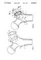
- FIG. 1is a posterior view of the upper portion of the right femur indicating an osteotomy line for a cut at the base of the greater trochanter and removal of a section of the greater trochanter in such a manner that it may be reattached by means of the present invention;
- FIG. 2is a posterior view of the femur of FIG. 1, wherein the greater trochanter section has been removed and prepared for reattachment in accordance with the present invention
- FIG. 3is a top plan view of the upper surface of one embodiment of the clamp of the present invention.
- FIG. 4is a side plan view of the trochanter clamp of FIG. 3;
- FIG. 5is a plan view of the underside of the clamp of FIG. 3;
- FIG. 6is a perspective view of a swage designed for use with the clamp of FIGS. 1-4;
- FIG. 7is a posterior view of the femur of FIG. 2, wherein cable tensioners have been applied to tension the attachment cables;
- FIG. 8is a posterior view of the femur of FIG. 2 following reattachment of the greater trochanter and illustrating the completed installation of the clamp and removed trochanter section;
- FIG. 9is a plan view of the upper surface of a second embodiment of the trochanter clamp of the present invention.
- FIG. 10is a side plan view of the clamp of FIG. 9;
- FIG. 11is a bottom plan view of the clamp of FIG. 9;
- FIG. 12is a sectional view of the clamp of FIG. 9, looking along the section line 12--12 in FIG. 9.
- reference letter Fidentifies a femur which has a greater trochanter T1 and a lesser trochanter T2.
- the femur Fhas been marked with an osteotomy cut line X in preparation for removal of a fragment or section W of the greater trochanter T1 in conjunction with hip surgery.
- the section Wis reattached by using a clamp 10 and surgical cables 50, 52 and 54 as described below.
- a template(not shown) is overlaid on the outer surface of the greater trochanter T1 and a series of holes S are drilled.
- the osteotomy cutis then performed along an L-shaped cut line X and the resulting section W of the greater trochanter T1 is removed as shown in FIG. 1.
- An L-shaped osteotomy cutis preferred, since the resulting ledge L on the distal side provides greater rotational stability during healing.
- the clamp 10can be used with any other osteotomy cut used to remove the greater trochanter.
- the greater trochanter section Wis repositioned on the femur F.
- a trochanter clamp 10is positioned on greater trochanter section W, as shown, so that spikes 48 (FIG. 5), which project from the underside of the clamp 10, are aligned with holes S (FIG. 1).
- the section X with the clamp 10 in placeis then repositioned on the superior lateral surface of the greater frochanter T1.
- cable holes about 2.0 mm. in diameterdesignated by reference letters A, B, and C, are drilled through lesser trochant T2.
- the clamp 10as shown in detail in FIGS. 3-5, has an upper surface that is generally convex.
- a swage recess 12is formed in the outer surface of the clamp 10 and extends longitudinally from a proximal side 14 to a distal side 16.
- Three pairs of cable grooves 18, 26 and 34are formed in the outer surface of trochanter clamp 10, and extend in parallel alignment and generally perpendicular to the swage recess 12.
- the pairs of grooves 18, 26 and 34are respectively identified by reference numerals 20 and 22, 28 and 30, and 36 and 38, with the grooves in each pair separated by ridges 24, 32 and 40, respectively.
- the portions of the grooves adjacent to the recess 12are open and deep enough to accommodate lengths of surgical cables as discussed below.
- the groovesconform to the contour of the clamp and are covered so they open on the sides of the clamp 10 as shown in FIG. 4.
- the underside of the clamp 10(FIG. 5) is generally concave in shape.
- a plurality of spikes 48project from the underside of clamp 10 and operate to initially align and hold the clamp 10 on the greater trochanter section W and on the greater trochanter T1 so the cables can be installed.
- a length of cable 50is passed through the hole A with the ends located on both sides of the clamp 10 in close proximity to the grooves 20, 22.
- a second cable 52is passed through the hole B, with its ends positioned on both sides of the clamp 10 in close proximity to the grooves 36, 38.
- the cable 52could be looped around the base of the lesser trochanter T2 and hole B eliminated.
- a hole Cis drilled through the lateral cortex of femur F at a distance of about 2.0 to 2.5 cm. from the distal side 16 of the clamp 10.
- a cable 54is passed through the hole C so that its ends are positioned on both sides of the clamp 10 in close proximity to the grooves 28, 30.
- the cables 50, 52 and 54are about 1.6-2.0 mm. in diameter, with the holes A, B and C slightly larger.
- the cablesare preferably formed of braided strands of chrome-cobalt wire.
- a swage 56is provided for receiving the ends of each cable 50, 52 and 54 to hold them in place as described below.
- the swages 56are formed with a substantially rectangular cross-section, with a pair of parallel bores 58 to accommodate the cables 50, 52 or 54.
- the swages 56have concave-shaped sides so that they are easily grasped by a suitable crimping tool (not shown).
- the swages 56are inserted in the recess 12 so that the bores 58 are aligned with the adjacent cable grooves.
- the ends of the cables 50, 52 and 54are inserted through the bores 58 and grasped by cable tensioners T.
- the cable tensioners Tare used to apply tension to the cables 50, 52 and 54 until tension is evenly applied across the surface of clamp 10.
- the preferred tension in the wires 50, 52 and 54generally ranges from about 125-200 pounds.
- assembly of the cable systemis completed by crimping the swages 56 with a suitable crimping tool (not shown) such that the bores 58 collapse to pinch the cables 50, 52 and 54 for maintaining them in tension.
- the recess 12provides the necessary clearance for the crimping tool to grasp the swages 56.
- the tensioners Tare released and removed.
- the ends of the wires 50, 52 and 54are trimmed so that their ends lie within their respective grooves on the clamp 10.
- the trimming operationis preferably performed using a guillotine type cutter (not shown) to minimize the possibility of the cable ends fraying.
- the clampcould also be formed with countersunk holes (not shown) so that cancellous bone screws could be used as a supplemental connection to the underlying bone for additional initial stability.
- FIGS. 9-12show an alternative embodiment of the clamp, where a clamp 110 and swages 156 are formed as an integral piece.
- a swage recess 112extends along the longitudinal access of the clamp 110, from its proximal side 114 to its distal side 116.
- the swages 156are spaced along the recess 112, adjacent to grooves 118, 126 and 134 which are designed to accommodate the cables as discussed above in conjunction with the embodiment in FIGS. 1-8.
- Each swage section 156has a pair of cable holes 158 through which cables can be inserted from opposite directions discussed above.
- a center opening 160is provided to allow the swages to collapse on the cables more uniformly when the swage sections 156 are crimped.
- the grooves 118 and 134are generally perpendicular to the recess 112 for receiving the cable 50 and 52, respectively, as shown in FIGS. 7 and 8.
- the groove 126is flared at its outer ends to accommodate a cable such as the one illustrated with reference numeral 54 in FIGS. 7 and 8.
- the groove 126is flared in both directions so that the clamp can be installed without concern about whether the ends are facing the right direction.
- a plurality of spikes 148project from the curved undersurface of the clamp 110 to engage holes drilled in the femur for providing greater lateral and rotational stability when the clamp is first installed. Installation of the cables for this embodiment is the same as described above, with the use of cable tensioners and crimping tools.
- a greater trochanter or other bone sectioncan be reattached after surgery and held firmly in place during the healing process. Rotating and shifting of the clamp and reattached bone section when the patient walks or raises out of a sitting position are resisted because the cables and clamp are positioned to counteract the forces acting on the clamp.
Landscapes
- Health & Medical Sciences (AREA)
- Orthopedic Medicine & Surgery (AREA)
- Surgery (AREA)
- Life Sciences & Earth Sciences (AREA)
- Heart & Thoracic Surgery (AREA)
- Nuclear Medicine, Radiotherapy & Molecular Imaging (AREA)
- Engineering & Computer Science (AREA)
- Biomedical Technology (AREA)
- Neurology (AREA)
- Medical Informatics (AREA)
- Molecular Biology (AREA)
- Animal Behavior & Ethology (AREA)
- General Health & Medical Sciences (AREA)
- Public Health (AREA)
- Veterinary Medicine (AREA)
- Surgical Instruments (AREA)
Abstract
Description
1. Field of the Invention
The invention generally relates to an apparatus and method useful for the reattachment of a bone section removed during surgery and, more particularly, to a clamp and cable system for reattaching the dome portion of the greater trochanter to prevent migration of the removed bone section until it fuses to the remaining bone.
2. Description of the Related Art
Hip surgery often requires osteotomy of the dome portion of the greater trochanter to access the joint. Following such surgery it is important that the removed portion be clamped in place to promote efficient healing through fusion of the removed portion to the remainder of the femur.
Many surgeons simply reattach the removed trochanter section after implanting a hip prosthesis by wiring the section to the remainder of the trochanter. This has proved unsatisfactory because of forces that cause the section to shift or rotate when the patient is walking or raising from a seat. It is not uncommon for surgical wires to break because of the magnitude of such forces.
A trochanter reattachment system used in the past is known as the Dall-Miles system, described in U.S. Pat. No. 4,269,180. This system utilizes an H-shaped clamp which is held in place on the reattached bone section by teeth that engage the outer surface of the domed segment and others that are embedded. Cables are passed through holes in the bridge of the clamp and through holes drilled in the femur. The bridge of the clamp is crimped onto the cables to fix them in position.
The Dall-Miles system has experienced cable failure problems, which are believed to be caused by the sharp bends which the cables are forced to make as they exit the bridge of the clamp. Such failures result in the clamp loosening and tissue irritation caused by the frayed cable ends.
The Dall-Miles system is not particularly effective in providing rotational and vertical stability for the trochanter segment. Since the attachment cables must pass through the single bridge of the H-shaped clamp, the clamp can rotate about the bridge. Vertical stability is also lacking because the clamp is configured such that the cables must pass through the femur only in a single direction in the vicinity of the lesser trochanter.
Therefore, there is a perceived need for a device that can reliably reattach the greater trochanter to the femur following osteotomy, which provides maximum rotational and vertical stability, while minimizing the possibility of a failure resulting in loosening of the device or the necessity of its removal.
The present invention operates to stabilize and support the reattached greater trochanter section until it fuses to the femur. Rotational and vertical stability are provided. Proper healing is promoted by applying pressure evenly across the osteotomized surface.
A one-piece, bowl-shaped clamp is contoured to fit on the dome of the greater trochanter. The clamp is fixed and retained on the osteotomized trochanter section primarily through the use of surgical cables. Spikes project from the underside of the clamp to provide initial fixation and rotational stability and to prevent migration while union occurs at the osteotomy site.
In one embodiment, a central recess extends from the proximal to the distal aspect on the superior side of the clamp. Three pairs of cable grooves, designed to accommodate the cables used to anchor the clamp to the femur, intersect the central recess and extend along the full width of the clamp.
A swage is placed in the central recess in alignment with each pair of cable grooves for receiving the ends of a cable which is looped around the femur in various locations for holding the clamp in place. After the cables are tensioned, the swage is compressed to pinch the cables and hold them in place. The cable ends are trimmed to finalize the procedure.
In another embodiment of the present invention a series of spaced swages are formed integral with the clamp, each of which has a pair of openings for receiving the ends of a cable that fit in surface grooves or slots that extend across the face of the clamp.
The objects, advantages and features of the invention will become more apparent when the detailed description of exemplary embodiments is considered conjunction with the appended drawings, in which:
FIG. 1 is a posterior view of the upper portion of the right femur indicating an osteotomy line for a cut at the base of the greater trochanter and removal of a section of the greater trochanter in such a manner that it may be reattached by means of the present invention;
FIG. 2 is a posterior view of the femur of FIG. 1, wherein the greater trochanter section has been removed and prepared for reattachment in accordance with the present invention;
FIG. 3 is a top plan view of the upper surface of one embodiment of the clamp of the present invention;
FIG. 4 is a side plan view of the trochanter clamp of FIG. 3;
FIG. 5 is a plan view of the underside of the clamp of FIG. 3;
FIG. 6 is a perspective view of a swage designed for use with the clamp of FIGS. 1-4;
FIG. 7 is a posterior view of the femur of FIG. 2, wherein cable tensioners have been applied to tension the attachment cables;
FIG. 8 is a posterior view of the femur of FIG. 2 following reattachment of the greater trochanter and illustrating the completed installation of the clamp and removed trochanter section;
FIG. 9 is a plan view of the upper surface of a second embodiment of the trochanter clamp of the present invention;
FIG. 10 is a side plan view of the clamp of FIG. 9;
FIG. 11 is a bottom plan view of the clamp of FIG. 9;
FIG. 12 is a sectional view of the clamp of FIG. 9, looking along thesection line 12--12 in FIG. 9.
Referring to FIG. 1, reference letter F identifies a femur which has a greater trochanter T1 and a lesser trochanter T2. The femur F has been marked with an osteotomy cut line X in preparation for removal of a fragment or section W of the greater trochanter T1 in conjunction with hip surgery. Following removal of the section W and completion of the hip surgery, the section W is reattached by using a clamp 10 andsurgical cables
In preparing the greater trochanter T1, a template (not shown) is overlaid on the outer surface of the greater trochanter T1 and a series of holes S are drilled. The osteotomy cut is then performed along an L-shaped cut line X and the resulting section W of the greater trochanter T1 is removed as shown in FIG. 1. An L-shaped osteotomy cut is preferred, since the resulting ledge L on the distal side provides greater rotational stability during healing. However, the clamp 10 can be used with any other osteotomy cut used to remove the greater trochanter.
As shown in FIG. 2, upon completion of the surgery where a prosthetic hip is implanted, the greater trochanter section W is repositioned on the femur F. A trochanter clamp 10 is positioned on greater trochanter section W, as shown, so that spikes 48 (FIG. 5), which project from the underside of the clamp 10, are aligned with holes S (FIG. 1). The section X with the clamp 10 in place is then repositioned on the superior lateral surface of the greater frochanter T1. Following a check for positioning and alignment of the clamp 10, cable holes about 2.0 mm. in diameter, designated by reference letters A, B, and C, are drilled through lesser trochant T2.
The clamp 10, as shown in detail in FIGS. 3-5, has an upper surface that is generally convex. Aswage recess 12 is formed in the outer surface of the clamp 10 and extends longitudinally from a proximal side 14 to adistal side 16. Three pairs ofcable grooves grooves reference numerals ridges
The portions of the grooves adjacent to therecess 12 are open and deep enough to accommodate lengths of surgical cables as discussed below. At the outer edges of the clamp 10, the grooves conform to the contour of the clamp and are covered so they open on the sides of the clamp 10 as shown in FIG. 4.
The underside of the clamp 10 (FIG. 5) is generally concave in shape. A plurality ofspikes 48, about 10-15 mm. long, project from the underside of clamp 10 and operate to initially align and hold the clamp 10 on the greater trochanter section W and on the greater trochanter T1 so the cables can be installed.
As shown in FIG. 2, a length ofcable 50 is passed through the hole A with the ends located on both sides of the clamp 10 in close proximity to thegrooves second cable 52 is passed through the hole B, with its ends positioned on both sides of the clamp 10 in close proximity to thegrooves cable 52 could be looped around the base of the lesser trochanter T2 and hole B eliminated. A hole C is drilled through the lateral cortex of femur F at a distance of about 2.0 to 2.5 cm. from thedistal side 16 of the clamp 10. Acable 54 is passed through the hole C so that its ends are positioned on both sides of the clamp 10 in close proximity to thegrooves
Thecables
Aswage 56 is provided for receiving the ends of eachcable swages 56 are formed with a substantially rectangular cross-section, with a pair of parallel bores 58 to accommodate thecables swages 56 have concave-shaped sides so that they are easily grasped by a suitable crimping tool (not shown).
As shown in FIG. 7, theswages 56 are inserted in therecess 12 so that the bores 58 are aligned with the adjacent cable grooves. The ends of thecables cables wires
Referring to FIG. 8, assembly of the cable system is completed by crimping theswages 56 with a suitable crimping tool (not shown) such that the bores 58 collapse to pinch thecables recess 12 provides the necessary clearance for the crimping tool to grasp theswages 56. After theswages 56 are crimped, the tensioners T are released and removed. The ends of thewires
FIGS. 9-12 show an alternative embodiment of the clamp, where aclamp 110 andswages 156 are formed as an integral piece. Aswage recess 112 extends along the longitudinal access of theclamp 110, from its proximal side 114 to itsdistal side 116. Theswages 156 are spaced along therecess 112, adjacent togrooves
Eachswage section 156 has a pair ofcable holes 158 through which cables can be inserted from opposite directions discussed above. Acenter opening 160 is provided to allow the swages to collapse on the cables more uniformly when theswage sections 156 are crimped.
Thegrooves recess 112 for receiving thecable groove 126 is flared at its outer ends to accommodate a cable such as the one illustrated withreference numeral 54 in FIGS. 7 and 8. Thegroove 126 is flared in both directions so that the clamp can be installed without concern about whether the ends are facing the right direction.
A plurality ofspikes 148 project from the curved undersurface of theclamp 110 to engage holes drilled in the femur for providing greater lateral and rotational stability when the clamp is first installed. Installation of the cables for this embodiment is the same as described above, with the use of cable tensioners and crimping tools.
By using the clamps, along with the swages and cables described above, a greater trochanter or other bone section can be reattached after surgery and held firmly in place during the healing process. Rotating and shifting of the clamp and reattached bone section when the patient walks or raises out of a sitting position are resisted because the cables and clamp are positioned to counteract the forces acting on the clamp.
The foregoing disclosure and description of the invention are illustrative and explanatory thereof, and various changes in the size, shape and materials, as well as in the details of the illustrated construction may be made without departing from the spirit of the invention.
Claims (27)
1. An implant for use in reattaching a bone section following bone surgery, comprising:
(a) a plate-like member for fitting over at least a portion of the outer surface of the bone section to be reattached, the member having an inner surface for engaging the bone section and an outer surface facing away from the bone section and side walls extending between the inner and outer surface;
(b) the outer surface having at least one cable holding portion for holding a cable in wherein said cable holding portion includes at least one groove place;
(c) means, associated with the plate, for gripping the ends of a cable and holding the cable in tension on the cable holding portion; and
(d) a recess extending across at least a portion of the outer surface of the plate-like member for receiving said means for gripping and holding, said recess intersecting the cable holding portion.
2. The implant of claim 1, wherein the outer surface is generally convex and the inner surface is generally concave.
3. The implant of claim 1, wherein the cable holding portion comprises three pairs of parallel grooves extending across the entire outer surface, and a wall separating each of the three pairs of parallel grooves, said wall having a height lower than the height of the outer surface of the plate-like member.
4. The implant of claim 3, wherein the three pairs of parallel grooves each have central portions opening onto the outer surface and end portions connecting with the central portion and extending through the plate-like member to openings in the side walls of the plate-like member.
5. The implant of claim 1, wherein the means for gripping and holding includes a generally rectangular body with opposing concave sides and a pair of openings parallel to the concave sides for receiving the ends of the cable, the body being collapsible by a crimping tool for pinching the cable in the openings.
6. The implant of claim 5, wherein the openings the rectangular body extend axially therethrough.
7. The implant of claim 1, wherein the means or gripping and holding is formed integral with the plate-like member.
8. The implant of claim 1, wherein the plate-like member further includes a plurality of spikes projecting from the inner surface of the plate for engaging the bone surface.
9. An implant for use in reattaching a bone section following bone surgery, comprising:
(a) a plate-like member for fitting over at least a portion of the outer surface of the bone section to be reattached, the member having an inner surface for engaging the bone section and an outer surface facing away from the bone section;
(b) the outer surface having at least one cable holding portion for holding a cable in place;
(c) means, associated with the plate, for gripping the ends of a cable and holding the cable in tension on the cable holding portion, said means including a generally rectangular body with opposing concave sides and a pair of openings parallel to the concave sides for receiving ends of the cable, the body being collapsible by a crimping tool for pinching the cable in the openings.
10. The implant of claim 9, wherein the outer surface is generally convex and the inner surface is generally concave.
11. The implant of claim 9, wherein the cable holding portion comprises three pairs of parallel grooves extending across the entire outer surface, and a wall separating each of the three pairs of parallel grooves, said wall having a height lower than the height of the outer surface of the plate-like member.
12. The implant of claim 9, wherein the three pairs of parallel grooves each have central portions opening onto the outer surface and end portions connecting with the central portion and extending through the plate-like member to openings in the side walls of the plate-like member.
13. The implant of claim 9, wherein the openings in the rectangular body extends axially therethrough.
14. The implant of claim 9, wherein the plate-like member further includes a plurality of spikes projecting from the inner surface of the plate for engaging the bone surface.
15. A system for reattaching a removed bone section from the greater trochanter portion of a femur following hip surgery, comprising:
(a) a plate-like member for fitting over at least a portion of the outer surface of the bone section to be reattached, the member having an inner surface for engaging the bone section and an outer surface facing away from the bone section;
(b) the outer surface having a plurality of cable holding portions, said cable holding portions including pairs of grooves formed in the outer surface of the plate and extending laterally across the outer surface;
(c) a plurality of cables, at least two of which is for extending around the femur and into two of the pairs of grooves, and another of said cables for extending around the distal side of the greater trochanter and into a third pair of grooves, one end of each cable being positioned on one of the grooves of each pair and the other end on the other groove of each pair;
(d) means, associated with the plate, for gripping the ends of a cable and holding the cable in tension on the cable holding portion; and
(e) a recess in the outer surface extending perpendicular to the grooves for receiving said means for gripping and holding.
16. The system of claim 15, wherein said means for gripping and holding includes a compressible swage to be received in the recess for receiving the ends of the cable in each groove, the swages being compressible for pinching the cables and holding them in tension.
17. The system of claim 15, wherein a plurality of spikes project outwardly from the inner surface of the plate-like member.
18. A system for reattaching a removed bone section from the greater trochanter portion of a femur following hip surgery, comprising:
(a) a plate-like member for fitting over at least a portion of the outer surface of the bone section to be reattached, the member having an inner surface for engaging the bone section and an outer surface facing away from the bone section;
(b) the outer surface having a plurality of cable holding portions, said cable holding portions including pairs of grooves formed in the outer surface of the plate and extending laterally across and opening onto a portion of the outer surface, the grooves extending through the member and having openings at the ends of the member;
(c) a plurality of cables, at least one of which is for extending around the femur and into two of the grooves, and an other of said cables for extending around the distal side of the greater trochanter and into a third groove;
(d) means, associated with the plate, for gripping the ends of a cable and holding the cable in tension on the cable holding portion; and
(e) a recess, in the outer surface of the plate-like member, extending perpendicular to the grooves for receiving said means for gripping and holding, said recess intersecting each of the grooves.
19. The system of claim 18, wherein said means for gripping and holding includes a compressible swage to be received in the recess for receiving the ends of the cable in each groove, the swages being compressible for pinching the cables and holding them in tension.
20. The system of claim 18, wherein a plurality of spikes project outwardly from the inner surface of the plate-like member.
21. A method for reattaching a removed bone section, comprising the steps of:
(a) positioning a plate-like member on the outer surface of the removed section, the plate-like member having removable cable gripping and holding means on the outer surface;
(b) forming at least one hole in the bone on the opposite side of the removed bone section;
(c) wrapping at least one length of cable around the bone and through the opening, with both ends being passed through opposite sides of the cable gripping and holding means;
(d) tensioning the cable by pulling on the ends; and
(e) securing the cable gripping and holding means on the cable ends for holding the cable in tension.
22. The method of claim 21, and further including the steps of:
forming locating holes in the outer surface of a greater trochanter portion of a femur, which are aligned with spikes formed on the undersurface of the plate-like member;
removing a section off the greater trochanter, the holes extending into the bone beneath the removed section; and
inserting the spikes on the undersurface of the plate-like member into the holes when the plate-like member is positioned on the removed section of the greater trochanter.
23. The method of claim 22, and further including the step of:
forming two holes in the lesser trochanter spaced from each other and a third hole through the lateral cortex of the femur.
24. The method of claim 23, and further including the step of:
placing a plurality of compressible swages, one for each cable in a recess formed in the outer surface of the plate-like member; with openings in the swages adapted to receive the ends of the cables;
passing the cables over grooves formed in the outer surface of the plate-like member, one set for such cable, the grooves intersecting with the recesses, and into the openings in the swages; and
compressing the swages to secure the swages on to cables.
25. The method of claim 24, wherein the grooves are spaced from the proximal to the distal sides of the plate-like member, the cables in the proximal and distal sides being passed through the holes formed in the lesser trochanter, while the cable in the other groove being passed through the hole in the lateral cortex.
26. The method of claim 23, wherein the step of removing a section off of the greater trochanter includes making an L-shaped cut to form a ledge on the distal side of the cut.
27. The method of claim 23, and further including the steps of:
passing a first cable through one of the holes in the lesser trochanter and over one of the grooves;
passing a second cable through the second hole in the lesser trochanter and over a second grooves;
passing a third cable through the hole in the lateral cortex of the femur and over a third groove; and
tensioning the cables over the member.
Priority Applications (5)
| Application Number | Priority Date | Filing Date | Title |
|---|---|---|---|
| US07/994,320US5324291A (en) | 1992-12-21 | 1992-12-21 | Bone section reattachment apparatus and method |
| EP93310014AEP0604082A1 (en) | 1992-12-21 | 1993-12-13 | Attachment apparatus |
| AU52370/93AAU5237093A (en) | 1992-12-21 | 1993-12-14 | Attachment apparatus and method |
| CA002111540ACA2111540A1 (en) | 1992-12-21 | 1993-12-15 | Bone reattachment apparatus |
| JP5320195AJPH06217992A (en) | 1992-12-21 | 1993-12-20 | Equipment and method for installation |
Applications Claiming Priority (1)
| Application Number | Priority Date | Filing Date | Title |
|---|---|---|---|
| US07/994,320US5324291A (en) | 1992-12-21 | 1992-12-21 | Bone section reattachment apparatus and method |
Publications (1)
| Publication Number | Publication Date |
|---|---|
| US5324291Atrue US5324291A (en) | 1994-06-28 |
Family
ID=25540539
Family Applications (1)
| Application Number | Title | Priority Date | Filing Date |
|---|---|---|---|
| US07/994,320Expired - LifetimeUS5324291A (en) | 1992-12-21 | 1992-12-21 | Bone section reattachment apparatus and method |
Country Status (5)
| Country | Link |
|---|---|
| US (1) | US5324291A (en) |
| EP (1) | EP0604082A1 (en) |
| JP (1) | JPH06217992A (en) |
| AU (1) | AU5237093A (en) |
| CA (1) | CA2111540A1 (en) |
Cited By (73)
| Publication number | Priority date | Publication date | Assignee | Title |
|---|---|---|---|---|
| US5607430A (en)* | 1995-08-25 | 1997-03-04 | Biomet, Inc. | Bone stabilization implant having a bone plate portion with integral cable clamping means |
| US5665088A (en)* | 1993-10-06 | 1997-09-09 | Smith & Nephew Richards Inc. | Bone section reattachment apparatus and method |
| US5741259A (en)* | 1996-02-22 | 1998-04-21 | Chan; Kwan-Ho | Surgical fastener device for use in bone fracture fixation |
| US5797916A (en)* | 1996-12-10 | 1998-08-25 | Johnson & Johnson Professional, Inc. | Trochanteric reattachment cerclage device |
| US5810824A (en)* | 1997-02-13 | 1998-09-22 | Chan; Kwan-Ho | Surgical fastener assembly and method for bone fracture fixation |
| US5885289A (en)* | 1995-10-14 | 1999-03-23 | Muller; Paul A. | Puller for correcting an upper jaw |
| US5941881A (en)* | 1998-01-09 | 1999-08-24 | Medidea, Llc | Bone fastening apparatus and related procedures |
| US6093190A (en)* | 1998-08-12 | 2000-07-25 | Poly-4 Medical Inc. | Bone fixation apparatus and method |
| US6123709A (en)* | 1997-07-25 | 2000-09-26 | Jones; Andrew R. | Bone buttress plate and method of using same |
| US6183478B1 (en) | 1999-02-04 | 2001-02-06 | Depuy Orthopaedics, Inc. | Temporary fixation device |
| US6368326B1 (en) | 1998-09-28 | 2002-04-09 | Daos Limited | Internal cord fixation device |
| US20030225410A1 (en)* | 2001-05-23 | 2003-12-04 | Alan Chervitz | Apparatus and method for orthopedic fixation |
| US20040087954A1 (en)* | 2002-08-28 | 2004-05-06 | Allen C . Wayne | Systems, methods, and apparatuses for clamping and reclamping an orthopedic surgical cable |
| US20040127907A1 (en)* | 1998-09-28 | 2004-07-01 | Dakin Edward B. | Internal cord fixation device |
| US20050070904A1 (en)* | 2003-09-29 | 2005-03-31 | Darin Gerlach | Bone plates and bone plate assemblies |
| US20050182406A1 (en)* | 2004-01-23 | 2005-08-18 | Orbay Jorge L. | System for stabilization of fractures of convex articular bone surfaces including subchondral support structure |
| US6960213B2 (en) | 2001-05-23 | 2005-11-01 | Medicinelodge, Inc. | Apparatus and method for orthopedic fixation |
| US20060129151A1 (en)* | 2002-08-28 | 2006-06-15 | Allen C W | Systems and methods for securing fractures using plates and cable clamps |
| US20060149265A1 (en)* | 2004-09-07 | 2006-07-06 | Anthony James | Minimal thickness bone plate locking mechanism |
| US20060167464A1 (en)* | 2004-09-23 | 2006-07-27 | Allen C W | Systems, methods, and apparatuses for tensioning an orthopedic surgical cable |
| US20060189987A1 (en)* | 2002-05-30 | 2006-08-24 | Orbay Jorge L | Nail plate |
| US20060189996A1 (en)* | 2005-01-28 | 2006-08-24 | Orbay Jorge L | Nail plate and implantation jig therefor |
| US20060217814A1 (en)* | 2002-09-13 | 2006-09-28 | Smith & Nephew, Inc. | Hip prostheses |
| US20060235408A1 (en)* | 2001-11-09 | 2006-10-19 | Wang Robert C | Apparatus and methods for bone fracture fixation |
| US20060235407A1 (en)* | 2001-11-09 | 2006-10-19 | Wang Robert C | Apparatus and methods for bone fracture reduction and fixation |
| US7207993B1 (en) | 2000-02-03 | 2007-04-24 | Pioneer Laboratories, Inc. | Apparatus and method for repairing the femur |
| US20070093835A1 (en)* | 2005-09-19 | 2007-04-26 | Orbay Jorge L | Bone Fixation Plate with Complex Suture Anchor Locations |
| US20080077132A1 (en)* | 2006-09-25 | 2008-03-27 | Medoff Robert J | Bone fixation device having integral fixation member |
| US20080234679A1 (en)* | 2007-02-13 | 2008-09-25 | Sarin Vineel K | Trochanteric grip |
| US20080281430A1 (en)* | 2005-02-22 | 2008-11-13 | Kelman David C | Long Sleeves for Use with Stems |
| US20090018546A1 (en)* | 2007-07-11 | 2009-01-15 | Daley Robert J | Methods and apparatus for determining pin placement during hip surgery |
| US20090164026A1 (en)* | 2005-10-31 | 2009-06-25 | Hiroshi Mikami | Femoral Stem for Artificial Hip Joint and Artificial Hip Joint Including the Same |
| US20100045529A1 (en)* | 2007-03-16 | 2010-02-25 | Masahiko Shimizu | Antenna Positioning Method And Antenna Mounting Device For Communication Device, And Antenna Device |
| US20100114175A1 (en)* | 2006-04-25 | 2010-05-06 | Warsaw Orthopedic, Inc. | Facet Fusion Implants and Methods of Use |
| US20100131063A1 (en)* | 2007-02-26 | 2010-05-27 | Marvin Schwartz | Prosthesis for interpositional location between bone joint articular surfaces and method of use |
| US7780710B2 (en) | 2004-01-23 | 2010-08-24 | Depuy Products, Inc. | System for stabilization of fractures of convex articular bone surfaces including subchondral support structure |
| US20100274245A1 (en)* | 2003-11-21 | 2010-10-28 | Eduardo Gonzalez-Hernandez | Fracture fixation system |
| US20110152943A1 (en)* | 2009-12-22 | 2011-06-23 | Eduardo Gonzalez-Hernandez | Bone plate and tool assembly and method for use thereof |
| US8105367B2 (en) | 2003-09-29 | 2012-01-31 | Smith & Nephew, Inc. | Bone plate and bone plate assemblies including polyaxial fasteners |
| US20120191202A1 (en)* | 2009-06-23 | 2012-07-26 | Keith Borowsky | Shoulder Joint Repair |
| US8328807B2 (en) | 2008-07-09 | 2012-12-11 | Icon Orthopaedic Concepts, Llc | Ankle arthrodesis nail and outrigger assembly |
| US8382807B2 (en) | 2005-07-25 | 2013-02-26 | Smith & Nephew, Inc. | Systems and methods for using polyaxial plates |
| US8414584B2 (en) | 2008-07-09 | 2013-04-09 | Icon Orthopaedic Concepts, Llc | Ankle arthrodesis nail and outrigger assembly |
| US8469999B2 (en) | 2008-04-17 | 2013-06-25 | Eduardo Gonzalez-Hernandez | Soft tissue attachment system and clip |
| WO2013106911A1 (en)* | 2012-01-18 | 2013-07-25 | Marvin Schwartz | Mobile prosthesis for interpositional location between bone joint articular surfaces and method of use |
| US8764808B2 (en) | 2008-03-10 | 2014-07-01 | Eduardo Gonzalez-Hernandez | Bone fixation system |
| US8870963B2 (en) | 2010-10-27 | 2014-10-28 | Toby Orthopaedics, Inc. | System and method for fracture replacement of comminuted bone fractures or portions thereof adjacent bone joints |
| US8940028B2 (en) | 2005-07-25 | 2015-01-27 | Smith & Nephew, Inc. | Systems and methods for using polyaxial plates |
| US8961573B2 (en) | 2010-10-05 | 2015-02-24 | Toby Orthopaedics, Inc. | System and method for facilitating repair and reattachment of comminuted bone portions |
| US8968318B2 (en) | 2007-02-28 | 2015-03-03 | DePuy Synthes Products, LLC | Grooved crimp with a set screw |
| US8979940B2 (en)* | 2012-12-14 | 2015-03-17 | Biomet Manufacturing, Llc | Modular attachment mechanism in prosthetic implants |
| US9254154B2 (en) | 2011-03-03 | 2016-02-09 | Toby Orthopaedic, Inc. | Anterior lesser tuberosity fixed angle fixation device and method of use associated therewith |
| US9271772B2 (en) | 2011-10-27 | 2016-03-01 | Toby Orthopaedics, Inc. | System and method for fracture replacement of comminuted bone fractures or portions thereof adjacent bone joints |
| US9283008B2 (en) | 2012-12-17 | 2016-03-15 | Toby Orthopaedics, Inc. | Bone plate for plate osteosynthesis and method for use thereof |
| US9333014B2 (en) | 2013-03-15 | 2016-05-10 | Eduardo Gonzalez-Hernandez | Bone fixation and reduction apparatus and method for fixation and reduction of a distal bone fracture and malunion |
| US9345576B2 (en) | 2011-12-07 | 2016-05-24 | Smith & Nephew, Inc. | Orthopedic augments having recessed pockets |
| US9402667B2 (en) | 2011-11-09 | 2016-08-02 | Eduardo Gonzalez-Hernandez | Apparatus and method for use of the apparatus for fracture fixation of the distal humerus |
| US9439781B2 (en) | 2011-05-03 | 2016-09-13 | Smith & Nephew, Inc. | Patient-matched guides for orthopedic implants |
| US9526543B2 (en) | 2004-11-10 | 2016-12-27 | Biomet C.V. | Modular fracture fixation system |
| US9549768B2 (en) | 2014-04-17 | 2017-01-24 | Biomet Manufacturing, Llc | Medical implant system for securing bone fragments |
| EP3184064A1 (en) | 2015-12-23 | 2017-06-28 | Stryker European Holdings I, LLC | Bone plate with guiding channels or spacer members |
| US9707097B2 (en) | 2011-12-07 | 2017-07-18 | Smith & Nephew, Inc. | Orthopedic implant augments |
| US9730797B2 (en) | 2011-10-27 | 2017-08-15 | Toby Orthopaedics, Inc. | Bone joint replacement and repair assembly and method of repairing and replacing a bone joint |
| US9901451B2 (en) | 2010-06-08 | 2018-02-27 | Smith & Nephew, Inc. | Implant components and methods |
| CN109363804A (en)* | 2018-11-29 | 2019-02-22 | 北京爱康宜诚医疗器材有限公司 | Anchoring device |
| US10357295B1 (en) | 2013-11-13 | 2019-07-23 | Mohammed A. Hajianpour | Apparatus and method for connecting opposite ends of a surgical wire wrapped around an internal body structure |
| US10390866B2 (en) | 2011-06-15 | 2019-08-27 | Smith & Nephew, Inc. | Variable angle locking implant |
| US10993750B2 (en) | 2015-09-18 | 2021-05-04 | Smith & Nephew, Inc. | Bone plate |
| US20220151667A1 (en)* | 2013-03-15 | 2022-05-19 | Circumfix Solutions, Inc. | Sternum fixation device and method |
| US11813008B2 (en) | 2020-05-26 | 2023-11-14 | Howmedica Osteonics Corp. | Medial trochanteric plate fixation |
| US12290295B2 (en) | 2020-06-19 | 2025-05-06 | Circumfix Solutions, Inc. | Bone repair devices and methods |
| US12402924B2 (en) | 2021-07-29 | 2025-09-02 | Circumfix Solutions, Inc. | Bone repair devices and methods |
| US12433651B2 (en) | 2013-01-12 | 2025-10-07 | Circumfix Solutions, Inc. | Sternum fixation device and method |
Families Citing this family (4)
| Publication number | Priority date | Publication date | Assignee | Title |
|---|---|---|---|---|
| GB9715440D0 (en)* | 1997-07-22 | 1997-09-24 | Dall Desmond Meiring | Bone grip |
| JP3738183B2 (en)* | 1998-02-18 | 2006-01-25 | 株式会社アイメディック | Bone fixation cable sleeve system |
| US7476255B2 (en) | 2003-12-30 | 2009-01-13 | Depuy Products, Inc. | Soft tissue attachment system and method |
| CA2661444C (en)* | 2006-08-15 | 2015-12-29 | Swissmedtechsolutions Ag | Trochanter retention plate |
Citations (10)
| Publication number | Priority date | Publication date | Assignee | Title |
|---|---|---|---|---|
| US3654668A (en)* | 1970-05-15 | 1972-04-11 | Arthur I Appleton | Wrapping device |
| US4153953A (en)* | 1977-04-21 | 1979-05-15 | Grobbelaar Charl J | Prosthetic hip joint |
| US4269180A (en)* | 1978-03-30 | 1981-05-26 | Dall Desmond Meiring | Bone fastener for the greater trochanter |
| US4889110A (en)* | 1987-05-05 | 1989-12-26 | Yves Galline | Attaching device and tools for positioning same, especially for attaching the trochanter major to the femur |
| US4960420A (en)* | 1988-08-23 | 1990-10-02 | Marlowe Goble E | Channel ligament clamp and system |
| US4988351A (en)* | 1989-01-06 | 1991-01-29 | Concept, Inc. | Washer for use with cancellous screw for attaching soft tissue to bone |
| EP0441668A1 (en)* | 1990-02-08 | 1991-08-14 | Societe De Fabrication De Materiel Orthopedique Sofamor | Sacrum bearing block for rachidian osteosynthesis |
| US5147360A (en)* | 1990-02-19 | 1992-09-15 | Societe De Fabrication De Materiel Orthopedique | Osteosynthesis device for the correction of spinal curvatures |
| US5190545A (en)* | 1991-08-27 | 1993-03-02 | Pfizer Hospital Products Group, Inc. | Cerclage wire positioning insert |
| US5217497A (en)* | 1990-07-04 | 1993-06-08 | Mehdian Seyed M H | Apparatus for use in the treatment of spinal disorders |
Family Cites Families (5)
| Publication number | Priority date | Publication date | Assignee | Title |
|---|---|---|---|---|
| FR590290A (en)* | 1924-12-10 | 1925-06-13 | Collin & Cie | Osteosynthesis splint |
| US4003376A (en)* | 1975-08-25 | 1977-01-18 | Bio-Dynamics, Inc. | Apparatus for straightening the spinal column |
| DE7903184U1 (en)* | 1979-02-06 | 1979-05-03 | Howmedica International, Inc. Zweigniederlassung Kiel, 2301 Schoenkirchen | Implant for fixation of broken ribs |
| DE3803435C1 (en)* | 1988-02-05 | 1989-09-21 | Ethicon Gmbh & Co Kg, 2000 Norderstedt, De | Implanted splint for rib fractures |
| GB9206018D0 (en)* | 1992-03-19 | 1992-04-29 | Dall Desmond Meiring | Bone fixation system |
- 1992
- 1992-12-21USUS07/994,320patent/US5324291A/ennot_activeExpired - Lifetime
- 1993
- 1993-12-13EPEP93310014Apatent/EP0604082A1/ennot_activeWithdrawn
- 1993-12-14AUAU52370/93Apatent/AU5237093A/ennot_activeAbandoned
- 1993-12-15CACA002111540Apatent/CA2111540A1/ennot_activeAbandoned
- 1993-12-20JPJP5320195Apatent/JPH06217992A/enactivePending
Patent Citations (10)
| Publication number | Priority date | Publication date | Assignee | Title |
|---|---|---|---|---|
| US3654668A (en)* | 1970-05-15 | 1972-04-11 | Arthur I Appleton | Wrapping device |
| US4153953A (en)* | 1977-04-21 | 1979-05-15 | Grobbelaar Charl J | Prosthetic hip joint |
| US4269180A (en)* | 1978-03-30 | 1981-05-26 | Dall Desmond Meiring | Bone fastener for the greater trochanter |
| US4889110A (en)* | 1987-05-05 | 1989-12-26 | Yves Galline | Attaching device and tools for positioning same, especially for attaching the trochanter major to the femur |
| US4960420A (en)* | 1988-08-23 | 1990-10-02 | Marlowe Goble E | Channel ligament clamp and system |
| US4988351A (en)* | 1989-01-06 | 1991-01-29 | Concept, Inc. | Washer for use with cancellous screw for attaching soft tissue to bone |
| EP0441668A1 (en)* | 1990-02-08 | 1991-08-14 | Societe De Fabrication De Materiel Orthopedique Sofamor | Sacrum bearing block for rachidian osteosynthesis |
| US5147360A (en)* | 1990-02-19 | 1992-09-15 | Societe De Fabrication De Materiel Orthopedique | Osteosynthesis device for the correction of spinal curvatures |
| US5217497A (en)* | 1990-07-04 | 1993-06-08 | Mehdian Seyed M H | Apparatus for use in the treatment of spinal disorders |
| US5190545A (en)* | 1991-08-27 | 1993-03-02 | Pfizer Hospital Products Group, Inc. | Cerclage wire positioning insert |
Cited By (151)
| Publication number | Priority date | Publication date | Assignee | Title |
|---|---|---|---|---|
| US5665088A (en)* | 1993-10-06 | 1997-09-09 | Smith & Nephew Richards Inc. | Bone section reattachment apparatus and method |
| US5607430A (en)* | 1995-08-25 | 1997-03-04 | Biomet, Inc. | Bone stabilization implant having a bone plate portion with integral cable clamping means |
| US5885289A (en)* | 1995-10-14 | 1999-03-23 | Muller; Paul A. | Puller for correcting an upper jaw |
| US5741259A (en)* | 1996-02-22 | 1998-04-21 | Chan; Kwan-Ho | Surgical fastener device for use in bone fracture fixation |
| US5797916A (en)* | 1996-12-10 | 1998-08-25 | Johnson & Johnson Professional, Inc. | Trochanteric reattachment cerclage device |
| US5810824A (en)* | 1997-02-13 | 1998-09-22 | Chan; Kwan-Ho | Surgical fastener assembly and method for bone fracture fixation |
| US6123709A (en)* | 1997-07-25 | 2000-09-26 | Jones; Andrew R. | Bone buttress plate and method of using same |
| US5941881A (en)* | 1998-01-09 | 1999-08-24 | Medidea, Llc | Bone fastening apparatus and related procedures |
| US6093190A (en)* | 1998-08-12 | 2000-07-25 | Poly-4 Medical Inc. | Bone fixation apparatus and method |
| US6368326B1 (en) | 1998-09-28 | 2002-04-09 | Daos Limited | Internal cord fixation device |
| US7410489B2 (en) | 1998-09-28 | 2008-08-12 | Daos Limited | Internal cord fixation device |
| US20040127907A1 (en)* | 1998-09-28 | 2004-07-01 | Dakin Edward B. | Internal cord fixation device |
| US6183478B1 (en) | 1999-02-04 | 2001-02-06 | Depuy Orthopaedics, Inc. | Temporary fixation device |
| US7207993B1 (en) | 2000-02-03 | 2007-04-24 | Pioneer Laboratories, Inc. | Apparatus and method for repairing the femur |
| US20050267476A1 (en)* | 2001-05-23 | 2005-12-01 | Alan Chervitz | Apparatus and method for orthopedic fixation |
| US20030225410A1 (en)* | 2001-05-23 | 2003-12-04 | Alan Chervitz | Apparatus and method for orthopedic fixation |
| US6960213B2 (en) | 2001-05-23 | 2005-11-01 | Medicinelodge, Inc. | Apparatus and method for orthopedic fixation |
| US8617221B2 (en) | 2001-11-09 | 2013-12-31 | Board Of Regents Of The Nevada System Of Higher Education, On Behalf Of The University Of Nevada, Reno | Apparatus and methods for bone fracture fixation |
| US20060235408A1 (en)* | 2001-11-09 | 2006-10-19 | Wang Robert C | Apparatus and methods for bone fracture fixation |
| US20110218535A1 (en)* | 2001-11-09 | 2011-09-08 | Wang Robert C | Apparatus and methods for bone fracture fixation |
| US7578835B2 (en)* | 2001-11-09 | 2009-08-25 | Board Of Regents Of The Nevada System Of Higher Education | Apparatus and methods for bone fracture reduction and fixation |
| US20060235407A1 (en)* | 2001-11-09 | 2006-10-19 | Wang Robert C | Apparatus and methods for bone fracture reduction and fixation |
| US20060189987A1 (en)* | 2002-05-30 | 2006-08-24 | Orbay Jorge L | Nail plate |
| US7938850B2 (en) | 2002-05-30 | 2011-05-10 | Depuy Products, Inc. | Nail plate |
| US7250054B2 (en) | 2002-08-28 | 2007-07-31 | Smith & Nephew, Inc. | Systems, methods, and apparatuses for clamping and reclamping an orthopedic surgical cable |
| US20060129151A1 (en)* | 2002-08-28 | 2006-06-15 | Allen C W | Systems and methods for securing fractures using plates and cable clamps |
| US20040097942A1 (en)* | 2002-08-28 | 2004-05-20 | Allen C. Wayne | System, methods, and apparatuses for clamping and reclamping an orthopedic surgical cable |
| US7255701B2 (en) | 2002-08-28 | 2007-08-14 | Smith & Nephew, Inc. | System, methods, and apparatuses for clamping and reclamping an orthopedic surgical cable |
| US20040087954A1 (en)* | 2002-08-28 | 2004-05-06 | Allen C . Wayne | Systems, methods, and apparatuses for clamping and reclamping an orthopedic surgical cable |
| US20060217814A1 (en)* | 2002-09-13 | 2006-09-28 | Smith & Nephew, Inc. | Hip prostheses |
| US8603182B2 (en) | 2002-09-13 | 2013-12-10 | Smith & Nephew, Inc. | Hip prostheses |
| US8753404B2 (en) | 2002-09-13 | 2014-06-17 | Smith & Nephew, Inc. | Hip prostheses |
| US20080015707A1 (en)* | 2002-09-13 | 2008-01-17 | Richard Lambert | Hip prostheses |
| US7179260B2 (en) | 2003-09-29 | 2007-02-20 | Smith & Nephew, Inc. | Bone plates and bone plate assemblies |
| US20050070904A1 (en)* | 2003-09-29 | 2005-03-31 | Darin Gerlach | Bone plates and bone plate assemblies |
| US8105367B2 (en) | 2003-09-29 | 2012-01-31 | Smith & Nephew, Inc. | Bone plate and bone plate assemblies including polyaxial fasteners |
| US20070162020A1 (en)* | 2003-09-29 | 2007-07-12 | Darin Gerlach | Bone plates and bone plate assemblies |
| US20070276386A1 (en)* | 2003-09-29 | 2007-11-29 | Darin Gerlach | Bone plate systems using provisional fixation |
| US8992581B2 (en) | 2003-09-29 | 2015-03-31 | Smith & Nephew, Inc. | Bone plate and bone plate assemblies including polyaxial fasteners |
| US20050107796A1 (en)* | 2003-09-29 | 2005-05-19 | Darin Gerlach | Bone plates and methods for provisional fixation using same |
| US7909858B2 (en) | 2003-09-29 | 2011-03-22 | Smith & Nephew, Inc. | Bone plate systems using provisional fixation |
| US7905910B2 (en) | 2003-09-29 | 2011-03-15 | Smith & Nephew, Inc. | Bone plates and bone plate assemblies |
| US8574234B2 (en) | 2003-11-21 | 2013-11-05 | Toby Orthopaedics, Inc. | Fracture fixation system |
| US8182485B1 (en) | 2003-11-21 | 2012-05-22 | Toby Orthopaedics, Llc | Fracture fixation system |
| US8361075B2 (en) | 2003-11-21 | 2013-01-29 | Toby Orthopaedics, Inc. | Method for repairing fractured bone |
| US20100274245A1 (en)* | 2003-11-21 | 2010-10-28 | Eduardo Gonzalez-Hernandez | Fracture fixation system |
| WO2005072284A3 (en)* | 2004-01-23 | 2005-11-10 | Hand Innovations Llc | System for stabilization of fractures of convex articular bone surfaces including subchondral support structure |
| US7744638B2 (en) | 2004-01-23 | 2010-06-29 | Depuy Products, Inc. | System for stabilization of fractures of convex articular bone surfaces including subchondral support structure |
| US7780710B2 (en) | 2004-01-23 | 2010-08-24 | Depuy Products, Inc. | System for stabilization of fractures of convex articular bone surfaces including subchondral support structure |
| US20050182406A1 (en)* | 2004-01-23 | 2005-08-18 | Orbay Jorge L. | System for stabilization of fractures of convex articular bone surfaces including subchondral support structure |
| US20090118773A1 (en)* | 2004-09-07 | 2009-05-07 | Anthony James | Minimal thickness bone plate locking mechanism |
| US20060149265A1 (en)* | 2004-09-07 | 2006-07-06 | Anthony James | Minimal thickness bone plate locking mechanism |
| US20060167464A1 (en)* | 2004-09-23 | 2006-07-27 | Allen C W | Systems, methods, and apparatuses for tensioning an orthopedic surgical cable |
| US8469966B2 (en) | 2004-09-23 | 2013-06-25 | Smith & Nephew, Inc. | Systems, methods, and apparatuses for tensioning an orthopedic surgical cable |
| US9913671B2 (en) | 2004-11-10 | 2018-03-13 | Biomet C.V. | Modular fracture fixation system |
| US9526543B2 (en) | 2004-11-10 | 2016-12-27 | Biomet C.V. | Modular fracture fixation system |
| US7896886B2 (en) | 2005-01-28 | 2011-03-01 | Depuy Products, Inc. | Nail plate and implantation jig therefor |
| US20060200157A1 (en)* | 2005-01-28 | 2006-09-07 | Orbay Jorge L | Nail Plate and Jig Therefor |
| US20060189996A1 (en)* | 2005-01-28 | 2006-08-24 | Orbay Jorge L | Nail plate and implantation jig therefor |
| US7927341B2 (en) | 2005-01-28 | 2011-04-19 | Depuy Products, Inc. | Nail plate and jig therefor |
| US20080281430A1 (en)* | 2005-02-22 | 2008-11-13 | Kelman David C | Long Sleeves for Use with Stems |
| US11896270B2 (en) | 2005-07-25 | 2024-02-13 | Smith & Nephew, Inc. | Systems and methods for using polyaxial plates |
| US8888824B2 (en) | 2005-07-25 | 2014-11-18 | Smith & Nephew, Inc. | Systems and methods for using polyaxial plates |
| US10092337B2 (en) | 2005-07-25 | 2018-10-09 | Smith & Nephew, Inc. | Systems and methods for using polyaxial plates |
| US10736680B2 (en) | 2005-07-25 | 2020-08-11 | Smith & Nephew, Inc. | Systems and methods for using polyaxial plates |
| US10292741B2 (en) | 2005-07-25 | 2019-05-21 | Smith & Nephew, Inc. | Systems and methods for using polyaxial plates |
| US8940028B2 (en) | 2005-07-25 | 2015-01-27 | Smith & Nephew, Inc. | Systems and methods for using polyaxial plates |
| US8382807B2 (en) | 2005-07-25 | 2013-02-26 | Smith & Nephew, Inc. | Systems and methods for using polyaxial plates |
| US10327822B2 (en) | 2005-07-25 | 2019-06-25 | Smith & Nephew, Inc. | Systems and methods for using polyaxial plates |
| US10080598B2 (en) | 2005-07-25 | 2018-09-25 | Smith & Nephew, Inc. | Systems and methods for using polyaxial plates |
| US12343053B2 (en) | 2005-07-25 | 2025-07-01 | Smith & Nephew, Inc. | Systems and methods for using polyaxial plates |
| US9795424B2 (en) | 2005-07-25 | 2017-10-24 | Smith & Nephew, Inc. | Systems and methods for using polyaxial plates |
| US20070093835A1 (en)* | 2005-09-19 | 2007-04-26 | Orbay Jorge L | Bone Fixation Plate with Complex Suture Anchor Locations |
| US7604657B2 (en) | 2005-09-19 | 2009-10-20 | Depuy Products, Inc. | Bone fixation plate with complex suture anchor locations |
| US20090164026A1 (en)* | 2005-10-31 | 2009-06-25 | Hiroshi Mikami | Femoral Stem for Artificial Hip Joint and Artificial Hip Joint Including the Same |
| US8252061B2 (en) | 2005-10-31 | 2012-08-28 | Hiroshi Mikami | Femoral stem for artificial hip joint and artificial hip joint including the same |
| US20100114175A1 (en)* | 2006-04-25 | 2010-05-06 | Warsaw Orthopedic, Inc. | Facet Fusion Implants and Methods of Use |
| US8070782B2 (en)* | 2006-04-25 | 2011-12-06 | Warsaw Orthopedic, Inc. | Facet fusion implants and methods of use |
| US20080077132A1 (en)* | 2006-09-25 | 2008-03-27 | Medoff Robert J | Bone fixation device having integral fixation member |
| US10463409B2 (en) | 2006-09-28 | 2019-11-05 | Biomet C.V. | Modular fracture fixation system |
| US20080234679A1 (en)* | 2007-02-13 | 2008-09-25 | Sarin Vineel K | Trochanteric grip |
| US20100131063A1 (en)* | 2007-02-26 | 2010-05-27 | Marvin Schwartz | Prosthesis for interpositional location between bone joint articular surfaces and method of use |
| US9510882B2 (en) | 2007-02-28 | 2016-12-06 | DePuy Synthes Products, Inc. | Grooved crimp with a set screw |
| US10512497B2 (en) | 2007-02-28 | 2019-12-24 | DePuy Synthes Products, Inc. | Grooved crimp with a set screw |
| US8968318B2 (en) | 2007-02-28 | 2015-03-03 | DePuy Synthes Products, LLC | Grooved crimp with a set screw |
| US20100045529A1 (en)* | 2007-03-16 | 2010-02-25 | Masahiko Shimizu | Antenna Positioning Method And Antenna Mounting Device For Communication Device, And Antenna Device |
| US20110208201A1 (en)* | 2007-07-11 | 2011-08-25 | Smith & Nephew, Inc. | Methods for determining pin placement during hip surgery |
| US8998916B2 (en) | 2007-07-11 | 2015-04-07 | Smith & Nephew, Inc. | Methods for determining pin placement during hip surgery |
| US20090018546A1 (en)* | 2007-07-11 | 2009-01-15 | Daley Robert J | Methods and apparatus for determining pin placement during hip surgery |
| US9439657B2 (en) | 2007-07-11 | 2016-09-13 | Smith & Nephew, Inc. | Methods and apparatus for determining pin placement during hip surgery |
| US8882780B2 (en) | 2007-07-11 | 2014-11-11 | Smith & Nephew, Inc. | Methods and apparatus for determining pin placement during hip surgery |
| US8764808B2 (en) | 2008-03-10 | 2014-07-01 | Eduardo Gonzalez-Hernandez | Bone fixation system |
| US8469999B2 (en) | 2008-04-17 | 2013-06-25 | Eduardo Gonzalez-Hernandez | Soft tissue attachment system and clip |
| US8690916B2 (en) | 2008-04-17 | 2014-04-08 | Eduardo Gonzalez-Hernandez | Soft tissue attachment system and clip |
| US8328807B2 (en) | 2008-07-09 | 2012-12-11 | Icon Orthopaedic Concepts, Llc | Ankle arthrodesis nail and outrigger assembly |
| US8414584B2 (en) | 2008-07-09 | 2013-04-09 | Icon Orthopaedic Concepts, Llc | Ankle arthrodesis nail and outrigger assembly |
| US9226783B2 (en) | 2008-07-09 | 2016-01-05 | Icon Orthopaedic Concepts, Llc | Ankle arthrodesis nail and outrigger assembly |
| US20120191202A1 (en)* | 2009-06-23 | 2012-07-26 | Keith Borowsky | Shoulder Joint Repair |
| US8579984B2 (en)* | 2009-06-23 | 2013-11-12 | Keith Borowsky | Shoulder joint repair |
| US20110152943A1 (en)* | 2009-12-22 | 2011-06-23 | Eduardo Gonzalez-Hernandez | Bone plate and tool assembly and method for use thereof |
| US9901451B2 (en) | 2010-06-08 | 2018-02-27 | Smith & Nephew, Inc. | Implant components and methods |
| US8961573B2 (en) | 2010-10-05 | 2015-02-24 | Toby Orthopaedics, Inc. | System and method for facilitating repair and reattachment of comminuted bone portions |
| US9271776B2 (en) | 2010-10-05 | 2016-03-01 | Toby Orthopaedics, Inc. | System and method for facilitating repair and reattachment of comminuted bone portions |
| US11266506B2 (en) | 2010-10-27 | 2022-03-08 | Toby Orthopaedics, Inc. | System for fracture replacement of comminuted bone fractures or portions thereof adjacent bone joints |
| US8870963B2 (en) | 2010-10-27 | 2014-10-28 | Toby Orthopaedics, Inc. | System and method for fracture replacement of comminuted bone fractures or portions thereof adjacent bone joints |
| US9757240B2 (en) | 2010-10-27 | 2017-09-12 | Toby Orthopaedics, Inc. | System and method for fracture replacement of comminuted bone fractures or portions thereof adjacent bone joints |
| US10524919B2 (en) | 2010-10-27 | 2020-01-07 | Toby Orthopaedics, Inc. | System and method for fracture replacement of comminuted bone fractures or portions thereof adjacent bone joints |
| US9254154B2 (en) | 2011-03-03 | 2016-02-09 | Toby Orthopaedic, Inc. | Anterior lesser tuberosity fixed angle fixation device and method of use associated therewith |
| US9439781B2 (en) | 2011-05-03 | 2016-09-13 | Smith & Nephew, Inc. | Patient-matched guides for orthopedic implants |
| US10390866B2 (en) | 2011-06-15 | 2019-08-27 | Smith & Nephew, Inc. | Variable angle locking implant |
| US10448980B2 (en) | 2011-06-15 | 2019-10-22 | Smith & Nephew, Inc. | Variable angle locking implant |
| US12390253B2 (en) | 2011-06-15 | 2025-08-19 | Smith & Nephew, Inc. | Variable angle locking implant |
| US10405901B2 (en) | 2011-06-15 | 2019-09-10 | Smith & Nephew, Inc. | Variable angle locking implant |
| US10188522B2 (en) | 2011-10-27 | 2019-01-29 | Toby Orthopaedics, Inc. | System for replacement of at least a portion of a carpal articular surface of a radius |
| US11129723B2 (en) | 2011-10-27 | 2021-09-28 | Toby Orthopaedics, Inc | System and method for fracture replacement of comminuted bone fractures or portions thereof adjacent bone joints |
| US9271772B2 (en) | 2011-10-27 | 2016-03-01 | Toby Orthopaedics, Inc. | System and method for fracture replacement of comminuted bone fractures or portions thereof adjacent bone joints |
| US11285020B2 (en) | 2011-10-27 | 2022-03-29 | Toby Orthopaedics, Inc. | Bone joint replacement and repair assembly and method of repairing and replacing a bone joint |
| US10299939B2 (en) | 2011-10-27 | 2019-05-28 | Toby Orthopaedics, Inc. | Bone joint replacement and repair assembly and method of repairing and replacing a bone joint |
| US9730797B2 (en) | 2011-10-27 | 2017-08-15 | Toby Orthopaedics, Inc. | Bone joint replacement and repair assembly and method of repairing and replacing a bone joint |
| US9402667B2 (en) | 2011-11-09 | 2016-08-02 | Eduardo Gonzalez-Hernandez | Apparatus and method for use of the apparatus for fracture fixation of the distal humerus |
| US9707097B2 (en) | 2011-12-07 | 2017-07-18 | Smith & Nephew, Inc. | Orthopedic implant augments |
| US10383744B2 (en) | 2011-12-07 | 2019-08-20 | Smith & Nephew, Inc. | Orthopedic implant augments |
| US9848989B2 (en) | 2011-12-07 | 2017-12-26 | Smith & Nephew, Inc. | Orthopedic augments having recessed pockets |
| US9814582B2 (en) | 2011-12-07 | 2017-11-14 | Smith & Nephew, Inc. | Orthopedic augments having recessed pockets |
| US12232978B2 (en) | 2011-12-07 | 2025-02-25 | Smith & Nephew, Inc. | Orthopedic implant augments |
| US9345576B2 (en) | 2011-12-07 | 2016-05-24 | Smith & Nephew, Inc. | Orthopedic augments having recessed pockets |
| US11344432B2 (en) | 2011-12-07 | 2022-05-31 | Smith & Nephew, Inc. | Orthopedic implant augments |
| US10265178B2 (en) | 2011-12-07 | 2019-04-23 | Smith & Nephew, Inc. | Orthopedic augments having recessed pockets |
| US11135067B2 (en) | 2011-12-07 | 2021-10-05 | Smith & Nephew, Inc. | Orthopedic augments having recessed pockets |
| WO2013106911A1 (en)* | 2012-01-18 | 2013-07-25 | Marvin Schwartz | Mobile prosthesis for interpositional location between bone joint articular surfaces and method of use |
| US8979940B2 (en)* | 2012-12-14 | 2015-03-17 | Biomet Manufacturing, Llc | Modular attachment mechanism in prosthetic implants |
| US11583324B2 (en) | 2012-12-17 | 2023-02-21 | Toby Orthopaedics, Llc | Bone plate for plate osteosynthesis and method for use thereof |
| US9956017B2 (en) | 2012-12-17 | 2018-05-01 | Toby Orthopaedics, Inc. | Bone plate for plate osteosynthesis and method for use thereof |
| US10835302B2 (en) | 2012-12-17 | 2020-11-17 | Toby Orthopaedics, Inc. | Bone plate for plate osteosynthesis and method for use thereof |
| US9283008B2 (en) | 2012-12-17 | 2016-03-15 | Toby Orthopaedics, Inc. | Bone plate for plate osteosynthesis and method for use thereof |
| US12433651B2 (en) | 2013-01-12 | 2025-10-07 | Circumfix Solutions, Inc. | Sternum fixation device and method |
| US20240173058A1 (en)* | 2013-03-15 | 2024-05-30 | Circumfix Solutions, Inc. | Sternum fixation device and method |
| US20220151667A1 (en)* | 2013-03-15 | 2022-05-19 | Circumfix Solutions, Inc. | Sternum fixation device and method |
| US11944362B2 (en)* | 2013-03-15 | 2024-04-02 | Circumfix Solutions, Inc. | Sternum fixation device and method |
| US9333014B2 (en) | 2013-03-15 | 2016-05-10 | Eduardo Gonzalez-Hernandez | Bone fixation and reduction apparatus and method for fixation and reduction of a distal bone fracture and malunion |
| US10357295B1 (en) | 2013-11-13 | 2019-07-23 | Mohammed A. Hajianpour | Apparatus and method for connecting opposite ends of a surgical wire wrapped around an internal body structure |
| US9549768B2 (en) | 2014-04-17 | 2017-01-24 | Biomet Manufacturing, Llc | Medical implant system for securing bone fragments |
| US11534213B2 (en) | 2015-09-18 | 2022-12-27 | Smith & Nephew, Inc. | Bone plate |
| US11974787B2 (en) | 2015-09-18 | 2024-05-07 | Smith & Nephew, Inc. | Bone plate |
| US10993750B2 (en) | 2015-09-18 | 2021-05-04 | Smith & Nephew, Inc. | Bone plate |
| US10517658B2 (en)* | 2015-12-23 | 2019-12-31 | Stryker European Holdings I, Llc | Bone plate with elongated guiding channels |
| EP3184064A1 (en) | 2015-12-23 | 2017-06-28 | Stryker European Holdings I, LLC | Bone plate with guiding channels or spacer members |
| CN109363804A (en)* | 2018-11-29 | 2019-02-22 | 北京爱康宜诚医疗器材有限公司 | Anchoring device |
| US11813008B2 (en) | 2020-05-26 | 2023-11-14 | Howmedica Osteonics Corp. | Medial trochanteric plate fixation |
| US12290295B2 (en) | 2020-06-19 | 2025-05-06 | Circumfix Solutions, Inc. | Bone repair devices and methods |
| US12402924B2 (en) | 2021-07-29 | 2025-09-02 | Circumfix Solutions, Inc. | Bone repair devices and methods |
Also Published As
| Publication number | Publication date |
|---|---|
| JPH06217992A (en) | 1994-08-09 |
| AU5237093A (en) | 1994-06-30 |
| CA2111540A1 (en) | 1994-06-22 |
| EP0604082A1 (en) | 1994-06-29 |
Similar Documents
| Publication | Publication Date | Title |
|---|---|---|
| US5324291A (en) | Bone section reattachment apparatus and method | |
| US5665088A (en) | Bone section reattachment apparatus and method | |
| US4269180A (en) | Bone fastener for the greater trochanter | |
| US6050998A (en) | Bone fastener | |
| US5797916A (en) | Trochanteric reattachment cerclage device | |
| EP1038503B1 (en) | Surgical fastener | |
| EP0600938B1 (en) | Cerclage wire positioning insert | |
| US5649927A (en) | Cable crimp system | |
| JP5176153B2 (en) | Trochanter holding plate | |
| EP0904036B1 (en) | Graft constraint device | |
| US7229444B2 (en) | Trochanteric cerclage plate | |
| US20040260296A1 (en) | Device and method of fastening a graft to a bone | |
| US6344042B1 (en) | Bone augmentation device | |
| JP4336076B2 (en) | Surgical cable crimp | |
| EP1464294B1 (en) | Greater trochanter re-attachment device | |
| CN111867489B (en) | Devices, systems and/or methods for repairing and attaching soft tissue to bone | |
| EP0615728A2 (en) | Orthopaedic reconstruction plate | |
| EP0893109A2 (en) | Apparatus and method for tibial fixation of soft tissue | |
| HK40072769A (en) | Method and apparatus for maintaining a position of a bone fragment in relationship to another bone part | |
| WO2023229839A1 (en) | Sheath assembly for sternal wire | |
| AU6838994A (en) | Surgical screw and washer |
Legal Events
| Date | Code | Title | Description |
|---|---|---|---|
| AS | Assignment | Owner name:SMITH & NEPHEW RICHARDS, INC., TENNESSEE Free format text:ASSIGNMENT OF ASSIGNORS INTEREST.;ASSIGNORS:RIES, MICHAEL;GIL, CARLOS E.;GARNER, STEVEN A.;REEL/FRAME:006462/0695;SIGNING DATES FROM 19930125 TO 19930203 | |
| STCF | Information on status: patent grant | Free format text:PATENTED CASE | |
| FPAY | Fee payment | Year of fee payment:4 | |
| FPAY | Fee payment | Year of fee payment:8 | |
| FPAY | Fee payment | Year of fee payment:12 |